Embed Size (px)
Citation preview
2007 PowerWorld Client Conference. October 25-26 © 2007 ISO New England Inc. 1
Automated Total Transfer Capability (TTC) Computations
Thermal Limits
By Slava Maslennikov, ISO New [email protected] (413) 540-4528

2007 PowerWorld Client Conference. October 25-26 © 2007 ISO New England Inc. 2
Outline of Presentation
• Overview of Objectives
• TTC Calculator: How it looks and what it does
• TTC Calculator: Design Features
• More details of supporting .aux files
• Near Future Plans

2007 PowerWorld Client Conference. October 25-26 © 2007 ISO New England Inc. 3
Overview of Objectives
2007 PowerWorld Client Conference. October 25-26 © 2007 ISO New England Inc. 4
Existing TTC calculation process
• Day Ahead Market (DAM): Thermal limits are calculated for five interfaces subject to N-2 contingencies (CTG)
• CTGs: Line + Line (2ndLine); Generator + Line (2ndGen)• Variety of EMS tools including Contingency Analysis,
Power Flow, linearized Interface Limit Calculation
Drawbacks • Process takes up to 10-12 hours/one person each day• Inconsistency of results day-to-day and person-to-person• Significant amount of manual work• “Last minute” changes difficult to apply
2007 PowerWorld Client Conference. October 25-26 © 2007 ISO New England Inc. 5
Requirements to new process for DAM
• Dramatic increase of efficiency and robustness• Day-to-day consistency of process/results. Eliminate
dependence of results on person performing calculations• Maximal automation and short learning curve to run
process
• Ability to consider a variety of scenarios for each interface
• Ability to adopt new process for Real Time operation and other markets (FTR, FCM)
2007 PowerWorld Client Conference. October 25-26 © 2007 ISO New England Inc. 6
PowerWorld: Pros for new TTC process
• ISO New England has the best implementation in industry achieving EMS model and PowerWorld synchronization
• Excellent flexibility and functionality of Power World as a research and engineering tool
• Fast and efficient work of Power World, Inc. staff to implement desirable to ISO-NE changes in software
• Availability of process automation tool - SimAuto
• Industry proven reputation of Power World (BPA, TVA, Entergy, etc)
2007 PowerWorld Client Conference. October 25-26 © 2007 ISO New England Inc. 7
PowerWorld: Cons to overcome in new process
• Complicated tool– A lot of parameters to be adjusted for proper ATC run– Long learning curve for a new user
• Vulnerability of data/settings from the unassuming user
2007 PowerWorld Client Conference. October 25-26 © 2007 ISO New England Inc. 8
TTC Calculator: How it looks and what it does

2007 PowerWorld Client Conference. October 25-26 © 2007 ISO New England Inc. 9
Step by Step Calculation process
Step 1: Prepare power flow case in EMS environment and convert it into .aux format
Step 2: Select pre-defined type of computations (All Interfaces, Single Interface, Single Scenario)
Step 3: Select pre-defined system conditions relevant to TTC calculations
Step 4: Push “Run” button
Step 5: Analyze results
In general, the calculations can be classified as “Push one button” process

2007 PowerWorld Client Conference. October 25-26 © 2007 ISO New England Inc. 10
Data Flow Chart
Script and data: .aux files- Source & Sink- Contingencies definition- Monitoring elements- Actions; Filters; SPS; etc.
Control-Scenario file.aux script
PowerWorld:- Simulator- SimAuto
Results- Excel .csv files- Reports
Power flow base cases: .aux files
Definitions: .csv files- Scenarios- Interfaces related data- Actions for interfacesRetriever
Converting EMS case to PowerWorld format
EMSPower flow cases
Dynamic data
TTC Calculator:- User Interface
- Script Generator
Relatively Static data
2007 PowerWorld Client Conference. October 25-26 © 2007 ISO New England Inc. 11
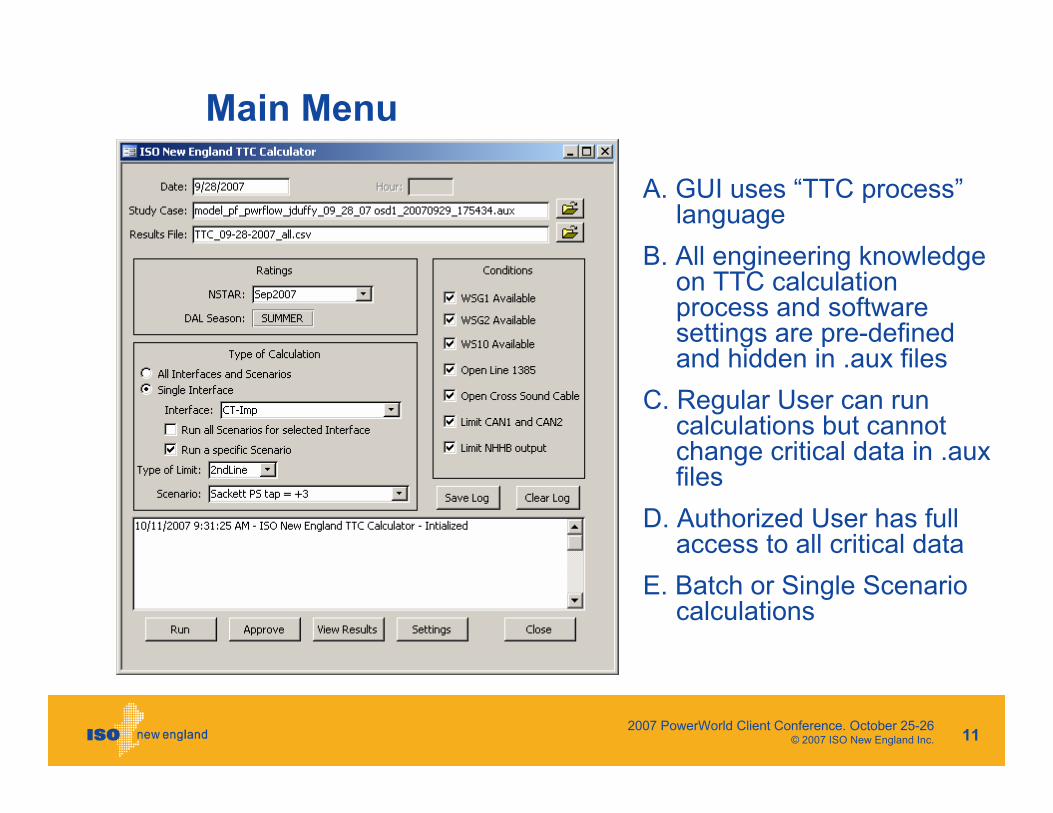
Main Menu
A. GUI uses “TTC process”language
B. All engineering knowledge on TTC calculation process and software settings are pre-defined and hidden in .aux files
C. Regular User can run calculations but cannot change critical data in .aux files
D. Authorized User has full access to all critical data
E. Batch or Single Scenario calculations
2007 PowerWorld Client Conference. October 25-26 © 2007 ISO New England Inc. 12
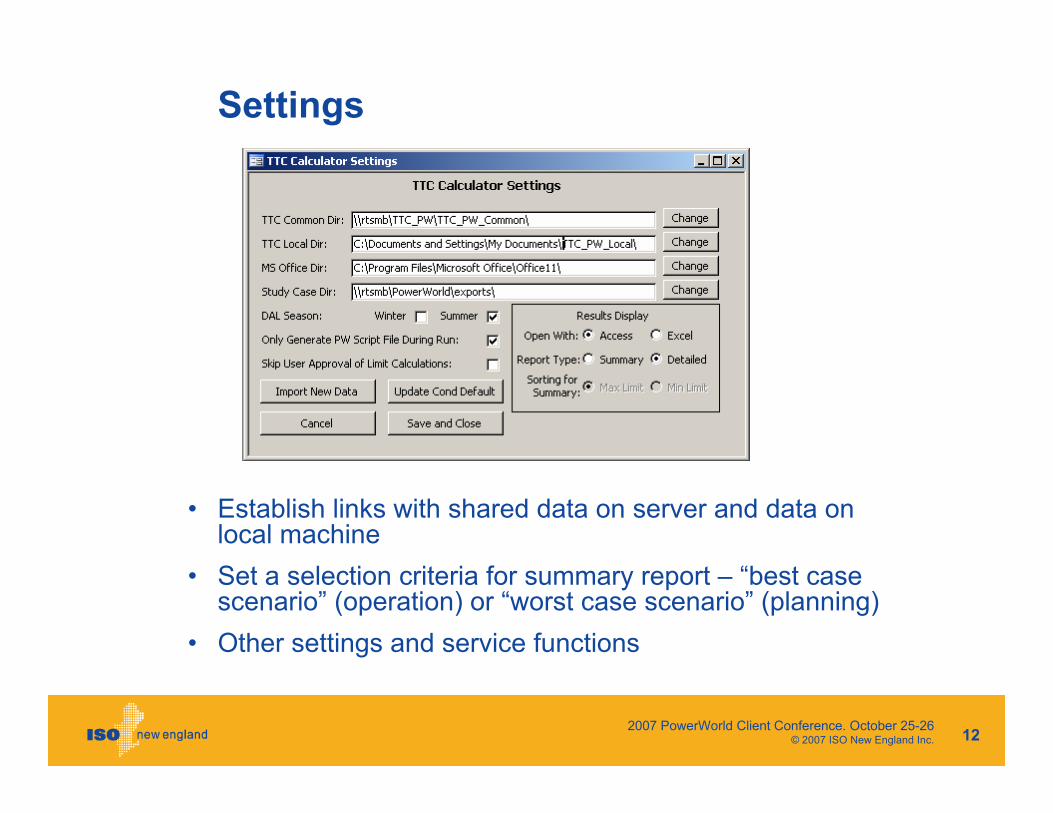
Settings
• Establish links with shared data on server and data on local machine
• Set a selection criteria for summary report – “best case scenario” (operation) or “worst case scenario” (planning)
• Other settings and service functions
2007 PowerWorld Client Conference. October 25-26 © 2007 ISO New England Inc. 13
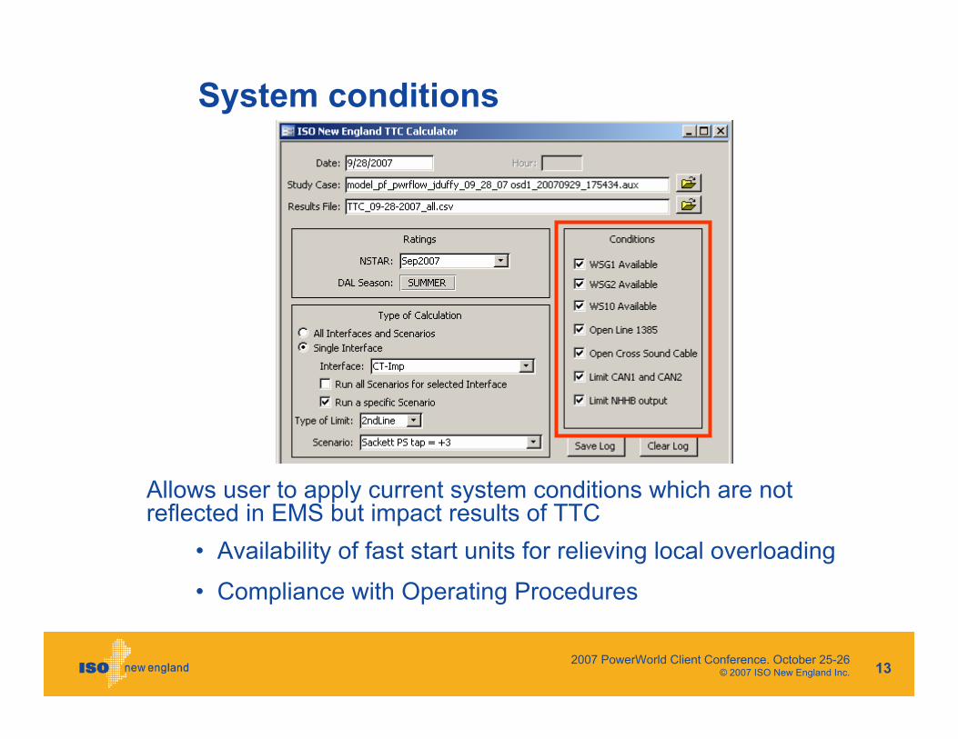
System conditions
Allows user to apply current system conditions which are not reflected in EMS but impact results of TTC
• Availability of fast start units for relieving local overloading
• Compliance with Operating Procedures
2007 PowerWorld Client Conference. October 25-26 © 2007 ISO New England Inc. 14
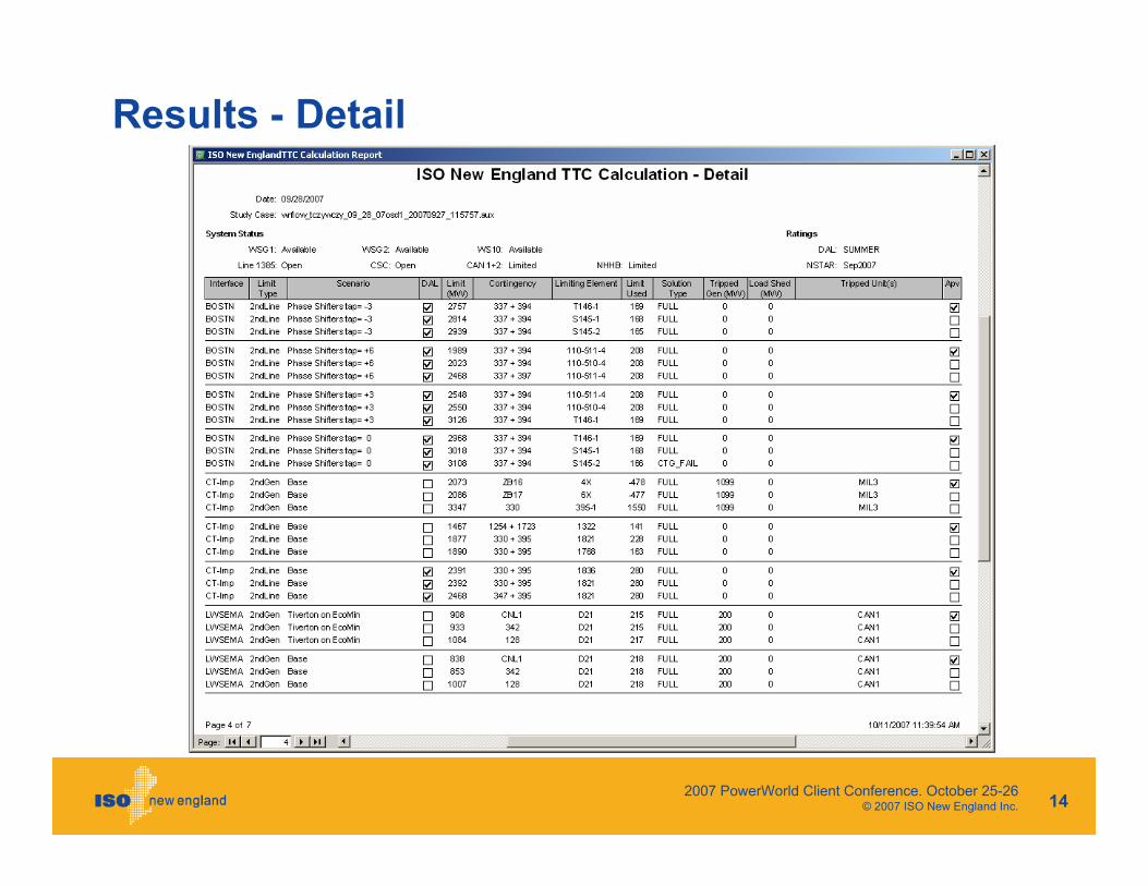
Results - Detail
2007 PowerWorld Client Conference. October 25-26 © 2007 ISO New England Inc. 15
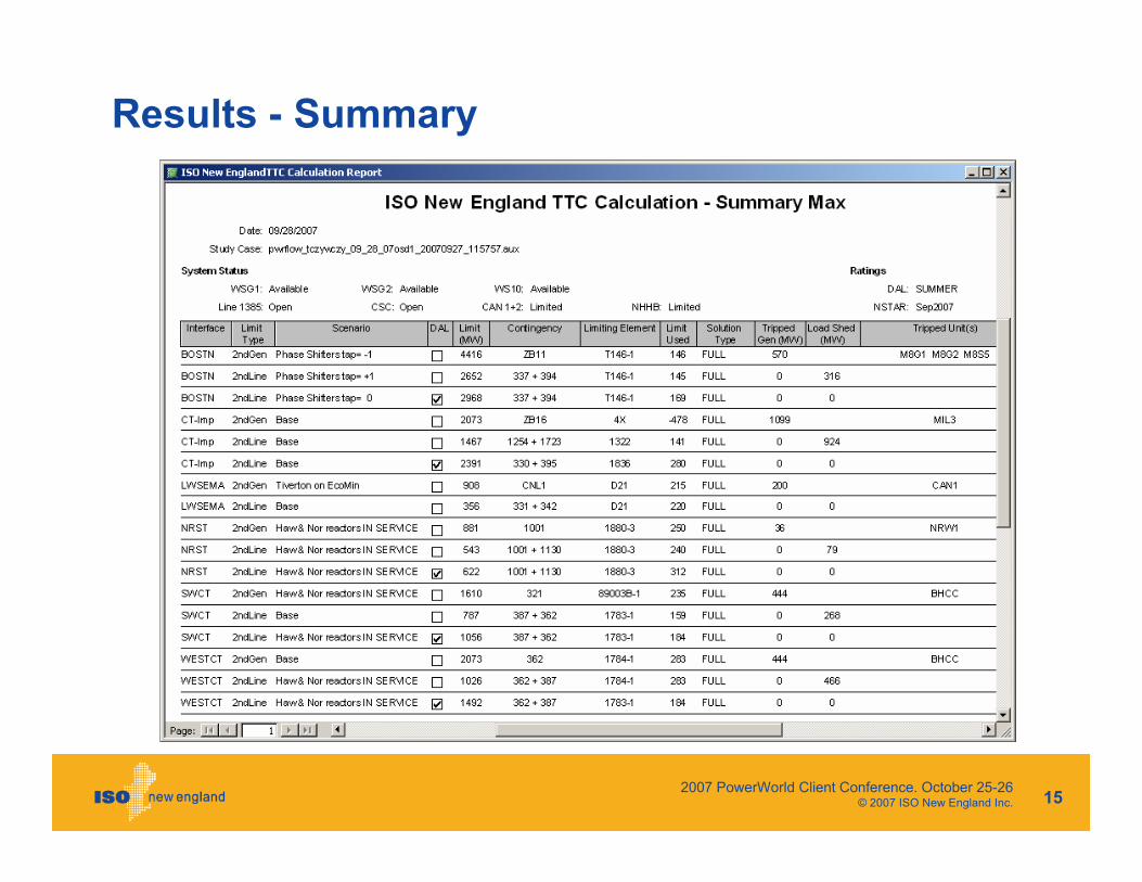
Results - Summary
2007 PowerWorld Client Conference. October 25-26 © 2007 ISO New England Inc. 16
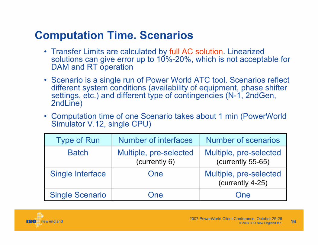
Computation Time. Scenarios
OneOneSingle Scenario
Multiple, pre-selected (currently 4-25)
OneSingle Interface
Multiple, pre-selected (currently 55-65)
Multiple, pre-selected (currently 6)
BatchNumber of scenariosNumber of interfacesType of Run
• Transfer Limits are calculated by full AC solution. Linearizedsolutions can give error up to 10%-20%, which is not acceptable for DAM and RT operation
• Scenario is a single run of Power World ATC tool. Scenarios reflect different system conditions (availability of equipment, phase shifter settings, etc.) and different type of contingencies (N-1, 2ndGen, 2ndLine)
• Computation time of one Scenario takes about 1 min (PowerWorld Simulator V.12, single CPU)

2007 PowerWorld Client Conference. October 25-26 © 2007 ISO New England Inc. 17
TTC Calculator: Major Accomplishments
• Dramatically increased process efficiency. Time reduction from 12hr to 1hr now, and to a few minutes in the near future
• Increased reliability and consistency of results by excluding all possible subjective factors and human errors
• Incorporation of expert engineering knowledge on TTC calculationprocess into formal .aux files and make them available for use by any user. Separating unassuming user from critical data.
• Very short learning curve for users with different backgrounds.
• Opportunity to adapt new process for Real Time operation and other applications (FTR, FCM)
“TTC Calculator” is the new level of application Power World tools in production environment
2007 PowerWorld Client Conference. October 25-26 © 2007 ISO New England Inc. 18
TTC Calculator: design features
2007 PowerWorld Client Conference. October 25-26 © 2007 ISO New England Inc. 19
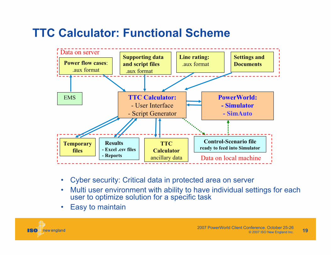
TTC Calculator: Functional Scheme
Power flow cases: .aux format
Supporting data and script files.aux format
Data on server
EMS
Temporary files
TTC Calculator
ancillary data
Line rating:.aux format
Settings and Documents
Data on local machine
Control-Scenario fileready to feed into Simulator
Results- Excel .csv files- Reports
TTC Calculator:- User Interface
- Script Generator
PowerWorld:- Simulator- SimAuto
• Cyber security: Critical data in protected area on server• Multi user environment with ability to have individual settings for each
user to optimize solution for a specific task• Easy to maintain
2007 PowerWorld Client Conference. October 25-26 © 2007 ISO New England Inc. 20
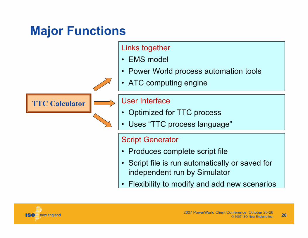
TTC Calculator User Interface• Optimized for TTC process• Uses “TTC process language”
Links together• EMS model • Power World process automation tools • ATC computing engine
Script Generator• Produces complete script file• Script file is run automatically or saved for
independent run by Simulator• Flexibility to modify and add new scenarios
Major Functions
2007 PowerWorld Client Conference. October 25-26 © 2007 ISO New England Inc. 21
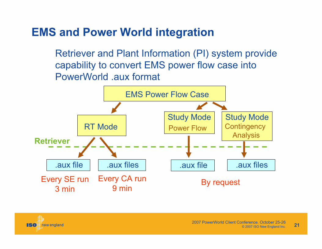
EMS and Power World integration
Retriever and Plant Information (PI) system provide capability to convert EMS power flow case into PowerWorld .aux format
EMS Power Flow Case
RT Mode Study ModePower Flow
.aux file .aux files .aux file .aux files
Study ModeContingency
Analysis
Every SE run3 min
Every CA run9 min
By request
Retriever
2007 PowerWorld Client Conference. October 25-26 © 2007 ISO New England Inc. 22
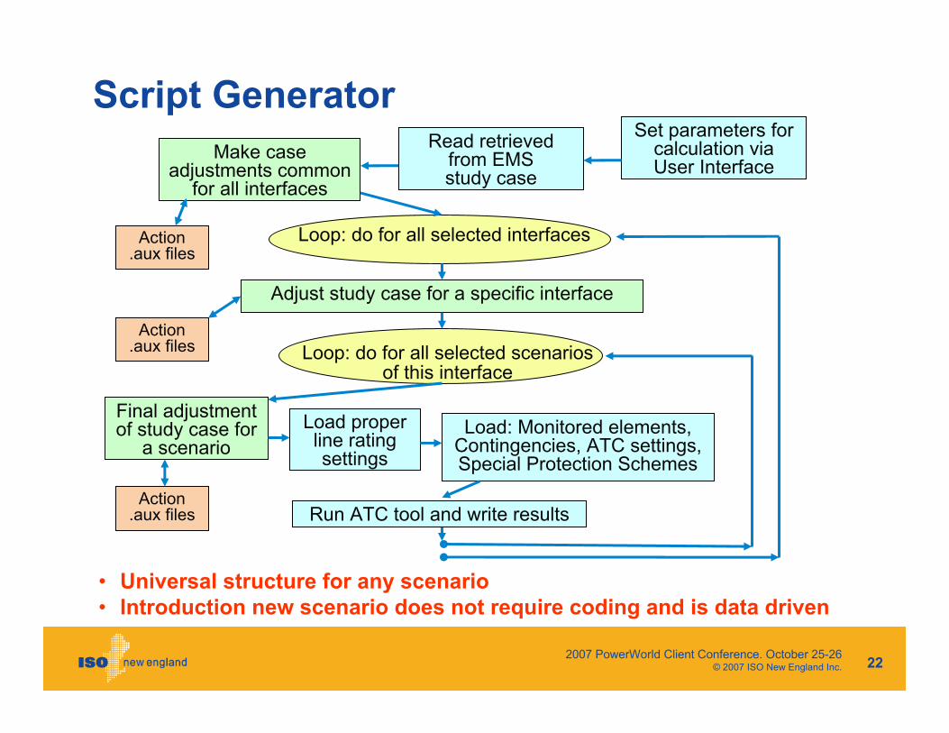
Script GeneratorSet parameters for
calculation via User Interface
Loop: do for all selected interfaces
Adjust study case for a specific interface
Loop: do for all selected scenarios of this interface
Run ATC tool and write results
Read retrieved from EMS study case
Make case adjustments common
for all interfaces
Final adjustment of study case for
a scenarioLoad proper line rating settings
Load: Monitored elements, Contingencies, ATC settings, Special Protection Schemes
• Universal structure for any scenario• Introduction new scenario does not require coding and is data driven
Action .aux files
Action .aux files
Action .aux files

2007 PowerWorld Client Conference. October 25-26 © 2007 ISO New England Inc. 23
More details of supporting .aux files
2007 PowerWorld Client Conference. October 25-26 © 2007 ISO New England Inc. 24
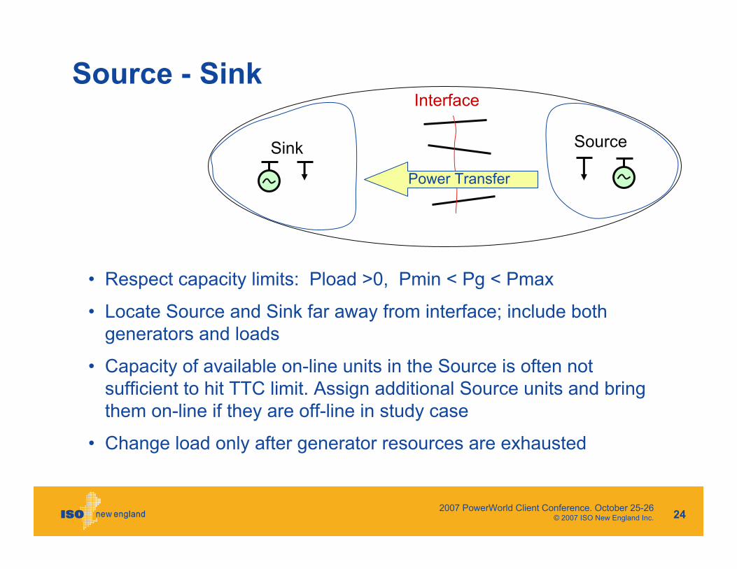
Source - Sink
• Respect capacity limits: Pload >0, Pmin < Pg < Pmax
• Locate Source and Sink far away from interface; include both generators and loads
• Capacity of available on-line units in the Source is often not sufficient to hit TTC limit. Assign additional Source units and bring them on-line if they are off-line in study case
• Change load only after generator resources are exhausted
Interface
Sink Source
Power Transfer

2007 PowerWorld Client Conference. October 25-26 © 2007 ISO New England Inc. 25
Monitored Elements
Selection of Monitored area as a compromise between
• Maximal system coverage around interface and
• Avoiding remote areas prone to local overloading due to relative arbitrariness of Source and Sink configuration and their day-to-day change
Monitored AreaSink Source
2007 PowerWorld Client Conference. October 25-26 © 2007 ISO New England Inc. 26
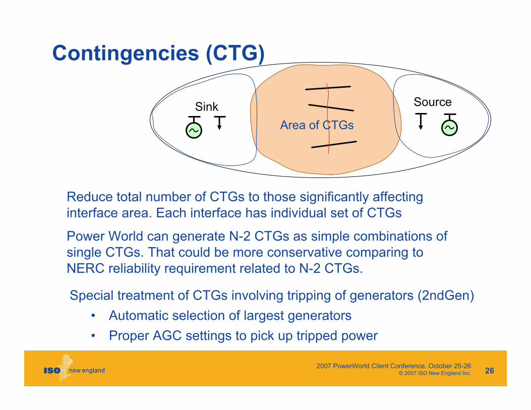
Contingencies (CTG)
Special treatment of CTGs involving tripping of generators (2ndGen)• Automatic selection of largest generators• Proper AGC settings to pick up tripped power
Area of CTGsSink Source
Reduce total number of CTGs to those significantly affecting interface area. Each interface has individual set of CTGs
Power World can generate N-2 CTGs as simple combinations of single CTGs. That could be more conservative comparing to NERC reliability requirement related to N-2 CTGs.

2007 PowerWorld Client Conference. October 25-26 © 2007 ISO New England Inc. 27
ATC Settings
Coordinated settings to get reliable and accurate solution at min time

2007 PowerWorld Client Conference. October 25-26 © 2007 ISO New England Inc. 28
Automatic following changes in EMS
Examples of developed at ISO-NE pertaining procedures:
• Load participation factors follow load weights in EMS load tree
• Generation of N-k contingencies based on CTG labels (like 337 + 394) and single CTG definition in EMS
EMS power system model experiences frequent changes and results of TTC Calculator must be consistent
To increase reliability and reduce maintenance efforts, design of supporting .aux files shall automatically incorporate ongoingEMS changes

2007 PowerWorld Client Conference. October 25-26 © 2007 ISO New England Inc. 29
Near Future Plans
2007 PowerWorld Client Conference. October 25-26 © 2007 ISO New England Inc. 30
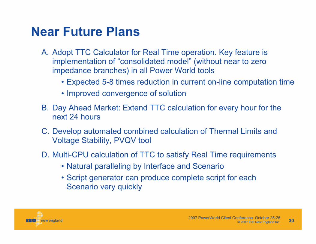
Near Future PlansA. Adopt TTC Calculator for Real Time operation. Key feature is
implementation of “consolidated model” (without near to zero impedance branches) in all Power World tools
• Expected 5-8 times reduction in current on-line computation time• Improved convergence of solution
B. Day Ahead Market: Extend TTC calculation for every hour for the next 24 hours
C. Develop automated combined calculation of Thermal Limits and Voltage Stability, PVQV tool
D. Multi-CPU calculation of TTC to satisfy Real Time requirements• Natural paralleling by Interface and Scenario• Script generator can produce complete script for each
Scenario very quickly

2007 PowerWorld Client Conference. October 25-26 © 2007 ISO New England Inc. 31
Thank you
Questions