Embed Size (px)
Citation preview

E X T R E M E B O L T I N G P R O J E C T
AUTOMATED SUBSEA BOLTING
Simon L inge
MFA Advanced Product Des ign Programme
Umeå Ins t i tu te o f Des ign, Umeå Univers i t y
2017

E X T R E M E B O L T I N G P R O J E C T
AUTOMATED SUBSEA BOLTING
Simon L inge
MFA Advanced Product Des ign Programme
Umeå Ins t i tu te o f Des ign, Umeå Univers i t y
2017
5ID096 Des ign Methodology
Super v i sor :
Thomas Degn
Acknowledgements :
Chr i s ter Bü low
Ola S t ray
Er ik Borg
Dan Tore Olsen
the workshop personnel a t UID
APD1 c lass o f 2016

TABLE OF CONTENTS
Abstract 7
Introduction 8
Method 11
Field Trip 11
Problem analysis 12
Design opportunity 19
Ideation 20
Refinement 26
Result 34
Reflection 45

ABSTRACT
This project focuses on how the sub sea bolt tensioning
procedure can be improved with the help of automation and
robotics in the form of a remotely operated underwater vehicle
(ROV). The resulting concept envisions a superior alternative
to the current standard in sub sea bolting. The benefits are
based on the fact that a human no longer need to be exposed to
the dangers of deep diving, as well as crucial functions that are
only possible in an automated system.
The work is based on a field trip that was conducted in
cooperation with and sponsored by Atlas Copco with an
end goal to explore new ways of developing hydraulic bolt
tensioning tools. Atlas Copco has been available for feedback
during various milestones during the project.
The final solution that is presented in this report is substantially
faster and safer than the current diving methods and make the
bolting solution more flexible, both in regards of time and
actual bolting scenario. The lack of human intervention also
reduces costs that may financially motivate the development
and retail of this product.

98
The principle of joining two parts with a nut and a bolt is
prevalent in an enormous array of products, from minute
electronics to vast bridges. The size of the nuts and bolts
vary according to the load that they need to withstand. This
project concerns the more extreme cases of bolt tightening
that are applied in the assembly of wind turbines and oil
platforms, to mention some applications.
Atlas Copco has been involved as a sponsor and advisor in
this project. They recently acquired a series of companies
that specialize in hydraulic tools and they currently offer
a range of bolt tightening solutions, their more traditional
electric and pneumatic solutions and their new line of
hydraulic tools.
Atlas Copco is a Swedish industrial company that was
founded in 1873. Atlas Copco companies develop,
manufacture, service, and rent industrial tools, air
compressors (of which it is the world’s leading producer),
construction and mining equipment such as rock drills,
assembly systems. The Group operates in four areas:
Compressor Technique, Mining and Rock Excavation
Technique, Construction Technique and Industrial
Technique. 1
The main benefits of hydraulic tools is that they can apply
greater force in a smaller package with superior precision
compared to other systems. Atlas Copco’s interest in
this project lies in how their newly acquired tools can be
improved, especially their usage scenarios.
INTRODUCTION
A sub sea bolt tensioner (right) and a series of conventional bolt tensioners in various sizes (above) that Atlas Copco currently offer 2
1. https://en.wikipedia.org/wiki/Atlas_Copco2. The image are courtesy of Atlas Copco

1110
The demonstration rig for hydraulic tools at Atlas Copco headquarters, Stockholm
METHOD
A field trip was arranged in order to for the students
to understand the tools Atlas Copco offers and to get
acquainted with the users of said tools. The trip started
with a visit at Atlas Copco headquarters in Stockholm,
Sweden. The class was received by Christer Bülow,
Business Development Manager, and Ashish Malhotra,
Global Product Manager.
The visit at Atlas Copco’s facilities in Stockholm provided
a basic understanding of how the tools work as well as their
benefits and issues. A seminar regarding ergonomics were
also presented.
The Human Centered Design Toolkit developed by IDEO
acted as a guide for the multiple interviews during the trip
in order to gather as much user information and reflections
as possible.
Human-Centered Design (HCD) is a process and a set
of techniques used to create new solutions for the world.
Solutions include products, services, environments,
organizations, and modes of interaction. The reason this
process is called “human-centered” is because it starts
with the people we are designing for. The HCD process
begins by examining the needs, dreams, and behaviors of
the people we want to affect with our solutions. We seek to
listen to and understand what they want. 1
The field trip continued to Stavanger, Norway since one of
Atlas Copco’s suppliers of hydraulic tools are based there;
kNm Hydraulikk. Christer Bülow and Erik Borg, an in-
house industrial designer at Atlas Copco, joined for the
rest of the trip since they, too, appreciated the chance to
encounter the users of their tools. A visit at a manufacturer
was arranged as well, Wepco, that use hydraulic bolting
tools daily.
Hydraulikk is a knowledgeable and experienced provider
of services and products within bolt tightening. They
provide Atlas Copco bolting tools. This offer consists
mainly of hydraulic torque tools and hydraulic tensioner
tools. They provide rule-based training programs and
courses in accordance to Norwegian Oil and Gas’s
guidelines. kNm Hydraulikk has people with extensive
experience from field work both onshore and offshore. 2
Wepco AS was established in 1986 and is today a
modern and well-equipped service workshop with highly
qualified personnel. Highly qualified employees and
modern machinery makes us able to take on assignments
that require a very high precision and quality level.
Wepco serves customers with high demands for flexible
production, short delivery and high quality. 3
Since the people that we met at kNm and Wepco are
veterans from the Norwegian oil and gas industry, they
provided another perspective on the tools. They elaborated
on some of the issues that they had found with the tools
during their long-time usage of them, which always is
interesting.
There was also and opportunity to visit an oil excavation
museum in Stavanger, The Norwegian Oil Museum.
This provided interesting information on the history of
the Norwegian oil industry and it’s impact on Norwegian
society.
1. https://botfl.nd.edu/pdf/IDEO%20Human%20Centered%20Design%20Toolkit.pdf2. http://www.knm-hydraulikk.no/om-knm-hydraulikk3. http://www.wepco.no/en-moderne-verksted-maskinering-og-produksjonsbedrift/
F I E L D T R I P

1312
Once back in Umeå after the trip, there followed a week
of group work in order to digest and sort the information
that was gathered during the study visits. Supervised by
Thomas Degn, the class was divided into smaller groups at
different stages during the week.
One of the main tasks was collecting, sharing and educate
each other on what tools that had been encountered and
how they work. Another was describing a believable persona
in order to create a holistic view of the users featured in
this project. A third one was acting out a scenario, again
based on a persona, and one or more conceptual tools that
would benefit that persona in some manner. There were
also several sessions where quick product concepts were
ideated, shared and discussed amongst the class.
These exercises served to produce ideas for how the bolt
tensioning environment could be improved and some of
those ideas served as underlay for some of the students’
product concepts.
P R O B L E M A N A L Y S I S
Visualizing the story about the persona (above) 1 and the collective ideation (below) 2
1. Image courtesy of Melissa Mahmutovic2. Image courtesy of Pontus Edman
1514
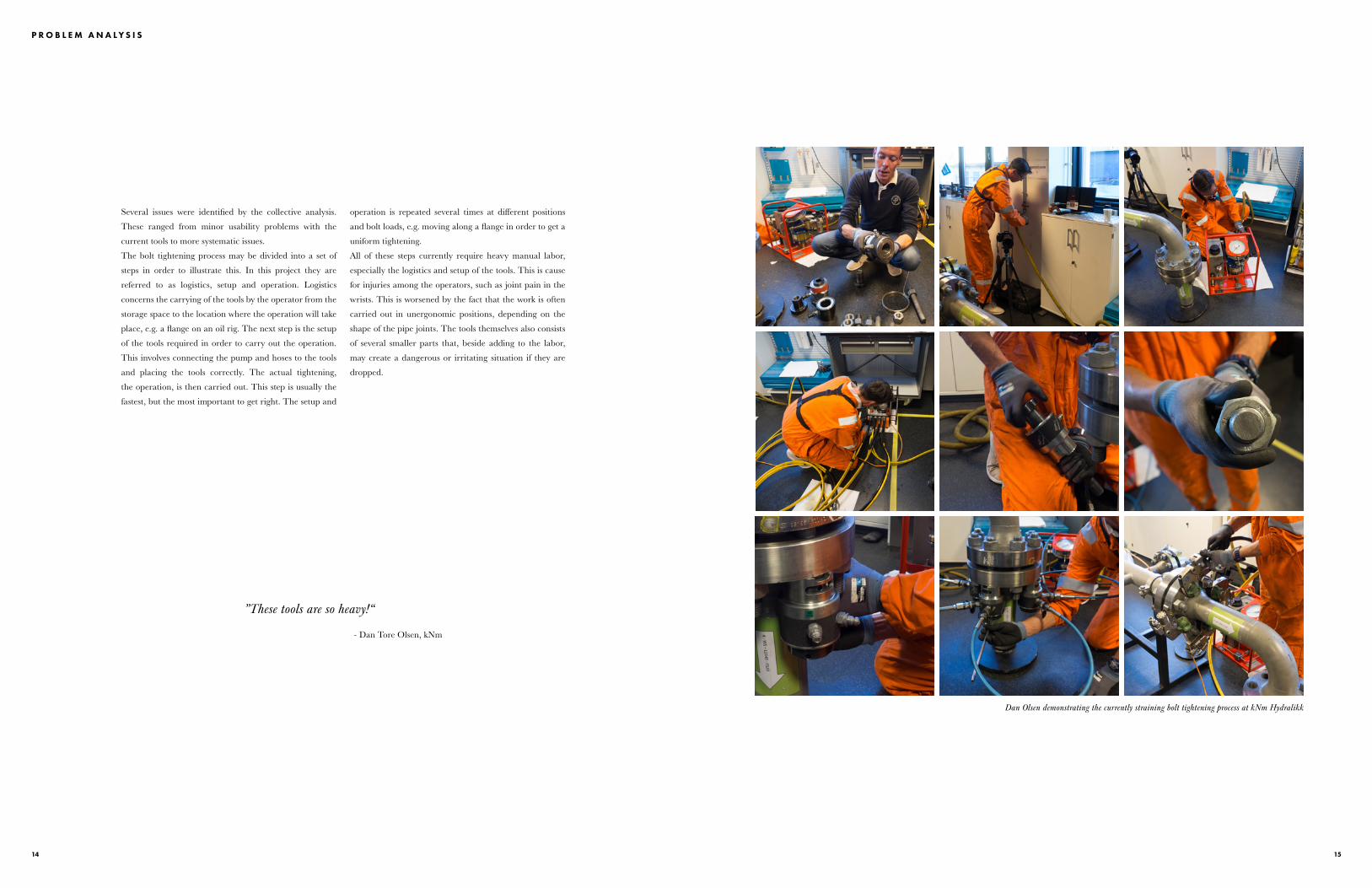
Several issues were identified by the collective analysis.
These ranged from minor usability problems with the
current tools to more systematic issues.
The bolt tightening process may be divided into a set of
steps in order to illustrate this. In this project they are
referred to as logistics, setup and operation. Logistics
concerns the carrying of the tools by the operator from the
storage space to the location where the operation will take
place, e.g. a flange on an oil rig. The next step is the setup
of the tools required in order to carry out the operation.
This involves connecting the pump and hoses to the tools
and placing the tools correctly. The actual tightening,
the operation, is then carried out. This step is usually the
fastest, but the most important to get right. The setup and
operation is repeated several times at different positions
and bolt loads, e.g. moving along a flange in order to get a
uniform tightening.
All of these steps currently require heavy manual labor,
especially the logistics and setup of the tools. This is cause
for injuries among the operators, such as joint pain in the
wrists. This is worsened by the fact that the work is often
carried out in unergonomic positions, depending on the
shape of the pipe joints. The tools themselves also consists
of several smaller parts that, beside adding to the labor,
may create a dangerous or irritating situation if they are
dropped.
P R O B L E M A N A L Y S I S
”These tools are so heavy!“
- Dan Tore Olsen, kNm
Dan Olsen demonstrating the currently straining bolt tightening process at kNm Hydralikk
1716
There is a specialized field within bolt tensioning which
is called subsea bolting. This entails all of the procedures
normally affiliated with bolt tensioning, with the addition
of every step of the tensioning process being carried out
under water several miles off-shore. It is reasonable that
this result in an already complex procedure being even
more straining for the operator. Fortunately, there are tools
that, due to the increased difficulty, can assist the operating
divers, to a point. One of these tools are the specialized sub
sea bolt tensioner that was presented in the introduction.
The diving equipment used for offshore work is chosen
to facilitate the work to be done while exposing the
personnel involved to an acceptably low level of risk.
When reasonably practicable, use of remotely operated
underwater vehicles is preferred, as this avoids exposing
the diver to underwater hazards. There is still a large
amount of underwater work for which diver intervention
is the only available alternative. 1
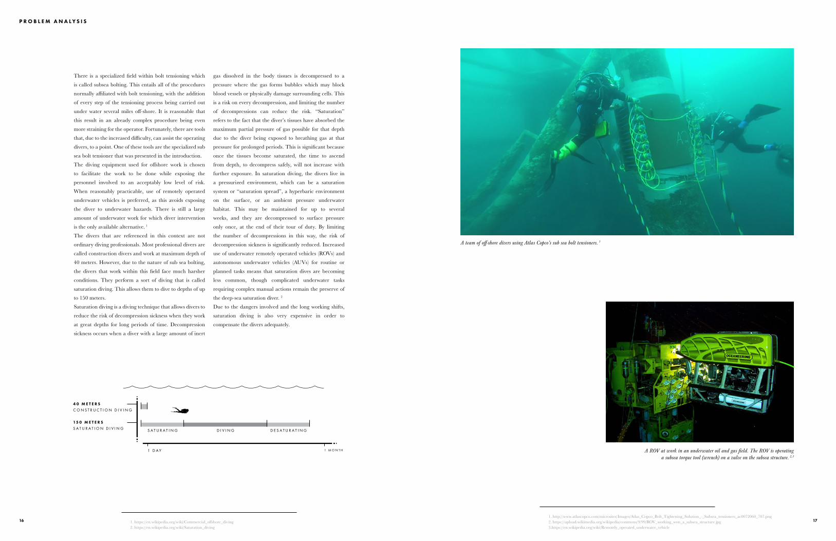
The divers that are referenced in this context are not
ordinary diving professionals. Most professional divers are
called construction divers and work at maximum depth of
40 meters. However, due to the nature of sub sea bolting,
the divers that work within this field face much harsher
conditions. They perform a sort of diving that is called
saturation diving. This allows them to dive to depths of up
to 150 meters.
Saturation diving is a diving technique that allows divers to
reduce the risk of decompression sickness when they work
at great depths for long periods of time. Decompression
sickness occurs when a diver with a large amount of inert
gas dissolved in the body tissues is decompressed to a
pressure where the gas forms bubbles which may block
blood vessels or physically damage surrounding cells. This
is a risk on every decompression, and limiting the number
of decompressions can reduce the risk. “Saturation”
refers to the fact that the diver’s tissues have absorbed the
maximum partial pressure of gas possible for that depth
due to the diver being exposed to breathing gas at that
pressure for prolonged periods. This is significant because
once the tissues become saturated, the time to ascend
from depth, to decompress safely, will not increase with
further exposure. In saturation diving, the divers live in
a pressurized environment, which can be a saturation
system or “saturation spread”, a hyperbaric environment
on the surface, or an ambient pressure underwater
habitat. This may be maintained for up to several
weeks, and they are decompressed to surface pressure
only once, at the end of their tour of duty. By limiting
the number of decompressions in this way, the risk of
decompression sickness is significantly reduced. Increased
use of underwater remotely operated vehicles (ROVs) and
autonomous underwater vehicles (AUVs) for routine or
planned tasks means that saturation dives are becoming
less common, though complicated underwater tasks
requiring complex manual actions remain the preserve of
the deep-sea saturation diver. 2
Due to the dangers involved and the long working shifts,
saturation diving is also very expensive in order to
compensate the divers adequately.
P R O B L E M A N A L Y S I S
1. https://en.wikipedia.org/wiki/Commercial_offshore_diving2. https://en.wikipedia.org/wiki/Saturation_diving
1 D A Y 1 M O N T H
15 0 M E T E R SS A T U R A T I O N D I V I N G
4 0 M E T E R SC O N S T R U C T I O N D I V I N G
S A T U R A T I N G D I V I N G D E S A T U R A T I N G
1. http://www.atlascopco.com/microsites/Images/Atlas_Copco_Bolt_Tightening_Solution_-_Subsea_tensioners_ac0072060_707.png2. https://upload.wikimedia.org/wikipedia/commons/9/99/ROV_working_won_a_subsea_structure.jpg3.https://en.wikipedia.org/wiki/Remotely_operated_underwater_vehicle
A ROV at work in an underwater oil and gas field. The ROV is operating a subsea torque tool (wrench) on a valve on the subsea structure. 2,3
A team of off-shore divers using Atlas Copco’s sub sea bolt tensioners. 1

1918
”FOCUS ON A NEW SYSTEM R ATHER THAN AN INCREMENTAL IMPROVEMENT - Christer Bülow, Atlas Copco
D E S I G N O P P O R T U N I T Y
AUTOMATED SUBSEA BOLTING
This project focuses on how the sub sea bolt tensioning
procedure can be improved with the help of automation
and robotics in the form of a remotely operated vehicle. The
expansion of technology in this field could help sidestep several
of the pain points that became apparent during the field trip
and the collective and individual analyses.
G O A L S A N D W I S H E S
D E S I G N A P R O D U C T T H A T . . .• I S A R E M O T E L Y O P E R A T E D V E H I C L E
• O P E R A T E S U N D E R W A T E R
• C A N R E P L A C E T H E D I V E R S
• C A N P E R F O R M T H E E N T I R E T E N S I O N I N G P R O C E D U R E
• M A K E S S U B S E A B O L T I N G F A S T E R A N D S A F E R
• I N C O R P O R A T E S A T L A S C O P C O ’ S F O R M L A N G U A G E
T H A T M A Y A L S O . . .• T A K E C U R R E N T S U B S E A W O R K F L O W I N T O C O N S I D E R A T I O N
• A C T I N D E P E N D E N T L Y F R O M C R E W
• F E A T U R E V I R T U A L R E A L I T Y A S A N I N T E R F A C E
• B E O P T I O N A L L Y I N T E R A C T I V E W I T H D I V E R S
• E X P L O R E A D D I T I O N A L M A R K E T S E G M E N T S F O R A T L A S C O P C O
• R E J U V E N A T E T H E S T A G N A T E D R O V M A R K E T
• D A N G E R O U S
• S L O W T E N S I O N I N G P R O C E D U R E
• E X P E N S I V E
• S L O W T O D E P L O Y
I D E N T I F I E D I S S U E S W I T H C U R R E N T S U B S E A B O L T I N G S C E N A R I O :

2120
I D E A T I O N
The ideation phase had a focus on sketching since there
were a lot of factors that were open to the imagination to
solve. The scenario, functionality and form of the design
lacked a specific point of reference, which meant that these
needed to be defined. In order to achieve that definition,
a series of identified issues were specified. Their purpose
was to get familiar with the project and explore different
concepts and ideas.
A selection of the primary problem areas were:
• Heavy lifts required to handle the tools
• Reduced speed under water
• Storage and transport of equipment
• Lack of leverage for applying force
These subjects served as the origin for the first batch of
ideation sketches.

2322
I D E A T I O N
The range of technologies that this product could
incorporate soon proved to be the quite wide. One way
of categorizing these technologies, and as a result the
product it self, is wether they created a product that would
be assistive to the divers or replace them entirely. Both
direction had strong merit. There are some tasks that an
autonomous robot probably never could do, at least in a
cost effective way, like taking a crucial intuitive decision,
thus divers will always be needed to some extent. The most
efficient way of improving the bolting scenario may then
be to help the divers perform their tasks in a more efficient
way.
The replacive direction has the big advantage of speed to
compensate for the lack of human insight since divers need
to be pressurized slowly for a long period of time in order
to handle deep diving. Still, divers normally only dive
to depths of 150 meters while ROVs can without much
difficulty exceed this and reach depths of so much as 6000
meters.
A S S I S T I V EC O - B O T
R E P L A C I V ER O B O T
M A I N L Y R E P L A C I V E
C O M B I N A T I O N
M A I N L Y A S S I S T I V E

2524
I D E A T I O N
C O M B O
A S S I S T I V E
R E P L A C I V E
+ I M P R O V E D I V E R ’ S W O R K F L O W
+ C O U L D W O R K W I T H A N D
W I T H O U T D I V E R
+ / - M A Y F A C I L I T A T E D R I V E R
- C O M P L E X
- L A R G E
- R O B O T I C D E V E L O P M E N T S T I L L
N E E D E D
- L O N G E R T O T A L P R O C E S S T I M E
T H A N R E P L A C I V E
+ I M P R O V E D I V E R ’ S W O R K F L O W
- S T I L L R E Q U I R E D I V E R
- L O N G E R T O T A L P R O C E S S T I M E
T H A N R E P L A C I V E
- S I M I L A R T O M O S T R O V S
+ N O D I V E R R E Q U I R E D
+ F A S T E R T O D E P L O Y
+ S A F E R
+ C H E A P E R O V E R T I M E
+ S I M I L A R P R O D U C T S E X I S T
T O D A Y
+ C A N B E M A D E C O M P A C T
- ” S K Y N E T F A C T O R ”
P R I N C I P L E C O N C E P T
The replacive concept was chosen as the direction that the
project would continue along due to it’s many benefits in
comparison to the other directions. While the form only
served as a placeholder, it served as a base to start to figure
out how the final design would work and what kind of
components that would be required in order to achieve
that functionality.
2726
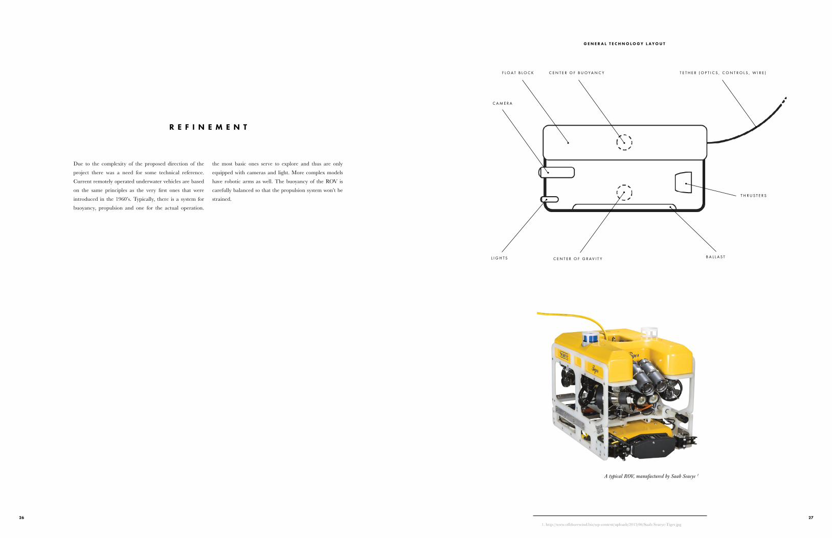
Due to the complexity of the proposed direction of the
project there was a need for some technical reference.
Current remotely operated underwater vehicles are based
on the same principles as the very first ones that were
introduced in the 1960’s. Typically, there is a system for
buoyancy, propulsion and one for the actual operation.
the most basic ones serve to explore and thus are only
equipped with cameras and light. More complex models
have robotic arms as well. The buoyancy of the ROV is
carefully balanced so that the propulsion system won’t be
strained.
R E F I N E M E N T
T E T H E R ( O P T I C S , C O N T R O L S , W I R E )C E N T E R O F B U O Y A N C Y
C E N T E R O F G R A V I T Y
F L O A T B L O C K
C A M E R A
L I G H T S B A L L A S T
T H R U S T E R S
1. http://www.offshorewind.biz/wp-content/uploads/2015/06/Saab-Seaeye-Tiger.jpg
A typical ROV, manufactured by Saab Seaeye 1
G E N E R A L T E C H N O L O G Y L A Y O U T

2928
I D E A T I O N
I N S P I R A T I O N B O A R D
This inspiration board served as personal motivation
in this project. The smooth, technical surfaces with the
intricate details underneath convey an interesting blend of
futurism and functionality.
F U T U R I S T I C
S M O O T H
F U N C T I O N A L
http://lazymk.deviantart.com/art/Mech-359978476http://www.g-mark.org/award/describe/40948?token=4z000RLtvkhttp://hexeract.tumblr.com/https://s-media-cache-ak0.pinimg.com/474x/89/9d/23/899d23d58c46607e8ba6f5cf04db3182.jpghttps://s-media-cache-ak0.pinimg.com/474x/22/e7/75/22e775de4840d8240bcced8b34fc6dcf.jpghttps://s-media-cache-ak0.pinimg.com/474x/3b/53/7d/3b537d97d22febef116b1c48d10b4a50.jpg
B R A N D B O A R D
While Atlas Copco’s form language varies between their
different product segments, there are some common clues
that are important to keep in mind in order for the final
product to fit their brand, such as the use of color and the
geometric shapes and the perceived ease of use.
C O L O R
G E O M E T R I C
U S A B I L I T Y
https://s-media-cache-ak0.pinimg.com/564x/cb/49/fe/cb49febe95ac4eb0efa283375a5d8823.jpghttp://www.flexibleassembly.com/Atlas-Copco-LTV-Angle-Air-Screwdriver.jpghttp://drillingtoday.com/december-2014/atlas-copcos-minetruck-mt42-gets-major-upgrade.phphttp://machinebuzz.blogspot.com/2012/11/atlas-copco-powerroc-t35.htmlhttp://red-dot.de/pd/online-exhibition/work/?lang=en&code=25-05068-2015&y=2015&c=168&a=0
3130
R E F I N E M E N T
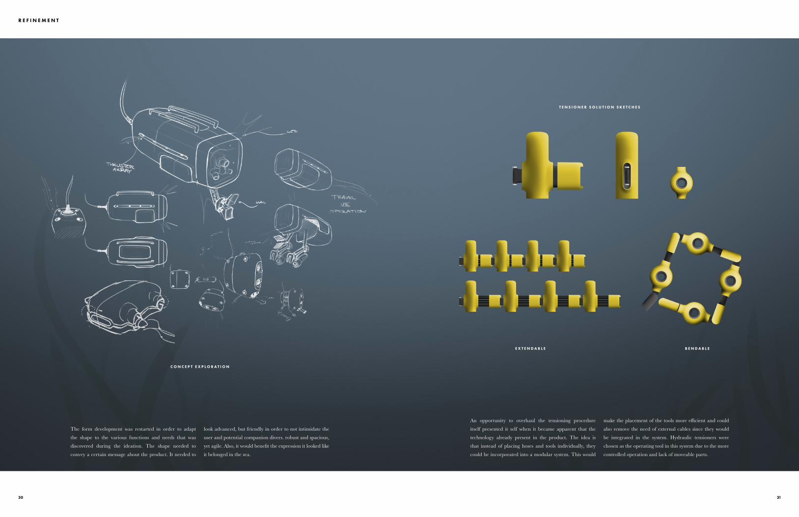
C O N C E P T E X P L O R A T I O N
The form development was restarted in order to adapt
the shape to the various functions and needs that was
discovered during the ideation. The shape needed to
convey a certain message about the product. It needed to
look advanced, but friendly in order to not intimidate the
user and potential companion divers. robust and spacious,
yet agile. Also, it would benefit the expression it looked like
it belonged in the sea.
E X T E N D A B L E B E N D A B L E
T E N S I O N E R S O L U T I O N S K E T C H E S
An opportunity to overhaul the tensioning procedure
itself presented it self when it became apparent that the
technology already present in the product. The idea is
that instead of placing hoses and tools individually, they
could be incorporated into a modular system. This would
make the placement of the tools more efficient and could
also remove the need of external cables since they would
be integrated in the system. Hydraulic tensioners were
chosen as the operating tool in this system due to the more
controlled operation and lack of moveable parts.

3332
R E F I N E M E N T
C O R D T O S U R F A C E
R A I L F O R A D D I N G E Q U I P M E N T
J E T T H R U S T E R S
M A G N E T I C C L A M P
T E N S I O N E R A R R A Y
P R O T E C T I V E H A T C H
L E F T , I N O P E R A T I O N
L E F T , I N T R A N S I T
F R O N T
T O P
L E D A R E A A R R A Y
V R C A M E R A S
P R O T E C T I V E G L A S S
14 8 0 m m
71 0 m m
6 4 0 m m
S E N T I E N T - A D V A N C E D - D E P E N D A B L EI C O N I C - F R I E N D L Y
The concept features clues from both Atlas Copco
industrial tools and from other Atlas Copco divisions, such
as the mining vehicles. The reason for this is mainly the size
of product. While it is roughly the same size as a human, it
is much larger than a hand held tool. Therefore the design
incorporates a layer strategy over a frame construction
that lets the components work unhindered and remain
accessible for maintenance. Extra attention was given to
the areas that are central to the products function, such as
the camera housing and the robotic arms.

3534
The Hydros concept envisions a superior alternative to
saturation diving in sub sea bolting. The benefits are based
on the fact that a human no longer need to be exposed to
the dangers of deep diving, as well as other functions that
are only possible in an automated system.
The solution is faster and safer than saturation diving and
make the bolting solution more flexible, both in regards
of time and function. The lack of human intervention
also reduces costs that may financially motivate the
development and retail of this product.
RESULT
I N T R O D U C I N G
H Y D R O SA N A T L A S C O P C O H Y D R O T E C T E N S I O N I N G S O L U T I O N

3736
R E S U L T
B E N D A B L E A N D E X T E N D A B L E C O N N E C T O R S
B A S E D O N C U R R E N T W I N D T U R B I N E T E N S I O N E R S
B U T T O N S F O R C O M P O N E N T E X C H A N G E
D E S I G N E D T O B E M O U N T E D A S A S E R I E S
E X C H A N G E A B L E N U T S O C K E T ,P U L L E R S L E E V E A N D B R I D G E
N E W T E N S I O N I N G S Y S T E M
The new tensioning system consists of a tensioner that is
based on current wind mill tensioners, which means that
the nut runner socket and puller sleeve can be electrically
fastened. Those two components, along with the bridge,
may be easily exchanged in this model when corresponding
button is pressed. The connectors between each tensioner
can extend and bend at a joint in order to adapt to different
flanges.
W R A P S A R O U N D F L A N G E
E X T E N D A B L E T E N S I O N E R A R R A Y S
The system makes for a much faster tensioning procedure
since it can mount all tensioners in a time frame that is
not much longer than mounting individual tensioners in
the conventional fashion. Also, the system would be able
to align the tensioners prior to mounting them since it
would know what sort of flange it would fasten, either via
recognition or pre loaded data.

3938
R E S U L T
A R E A L I G H T
T E N S I O N I N G S Y S T E M
P R O T E C T I V E S H E L L S
C O M M U N I C A T I O NC A B L E
C A M E R A &S E N S O R S
E X P L O D E D V I E W - E X T E R I O R
The most attention in the exterior design have been given
to the front of the design, where the main functionality of
the product is located. In the very front is a wide-angle
camera and other sensors that provide information to the
operator back on the ship on the devices location. This
information is transported via the cable which houses a
steel wire and fiber optics along with power supply. There
is a large area light around the camera that illuminates the
environment that Hydros is operating in, providing more
even light distribution due to the fact that it wraps around
the camera housing.
The tensioning system is folded into the body in order to
not get tangled or damaged during transport. The roof and
the belly features rails that provide utility and protection.
E X P L O D E D V I E W - I N T E R I O R
B U O Y A N C Y T A N K S
H Y D R A U L I C P U M P
U T I L I T Y R A I L S
P R O P E L L E R
C O N T R O L & C O M M U N I C A T I O N U N I T
T H R U S T E R S
P R O T E C T I V E R A I L S
The inside of the device features a central control unit that
makes the system run as intended. It also features a pump
for the hydraulic tensioning system. The hydraulic pump
also powers the propeller and the thrusters, making them
both powerful and operate smoothly.
Hydros features a buoyancy system that differs from
conventional ROVs. Since the weight of the product
may vary with the amount of tools it is equipped with, it
regulates it’s buoyancy with a set of air tanks, much like a
submarine does, making the buoyancy system very flexible.
This is also more material efficient than the conventional
foam blocks found in other ROVs.
4140
R E S U L T
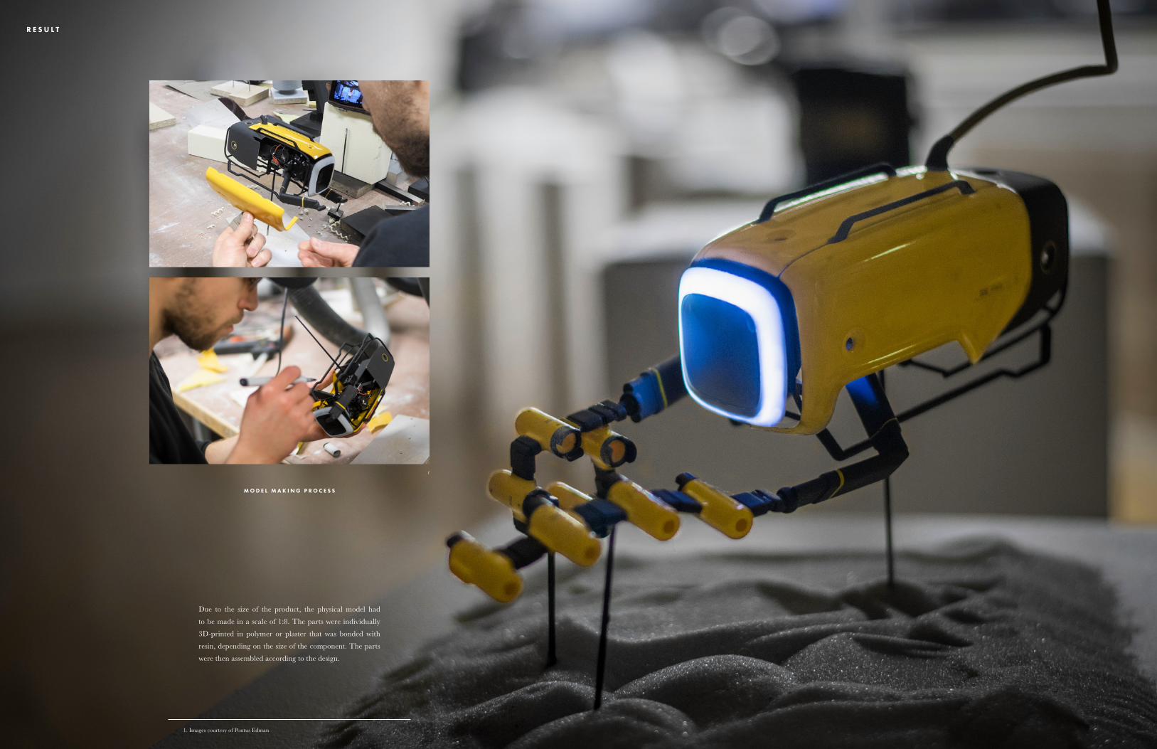
M O D E L M A K I N G P R O C E S S
Due to the size of the product, the physical model had
to be made in a scale of 1:8. The parts were individually
3D-printed in polymer or plaster that was bonded with
resin, depending on the size of the component. The parts
were then assembled according to the design.
1. Images courtesy of Pontus Edman
1

4342
R E S U L T
H Y D R O S
• F L E X I B L E D U E T O I N S T A N T D E P L O Y M E N T
• S A F E R D U E T O N O H U M A N E X P O S U R E T O H I G H P R E S S U R E
• T O U G H E R S I N C E I T C A N W I T H S T A N D H I G H E R P R E S S U R E
• C H E A P E R D U E T O L E S S D I V E R T I M E
1 D A Y 1 M O N T H
15 0 M E T E R SS A T U R A T I O N D I V I N G
6 0 0 + M E T E R SA U T O M A T E D D I V I N G
4 0 M E T E R SC O N S T R U C T I O N D I V I N G

4544
REFLECTION
I believe I succeeded with my goals for this project to a
satisfactory level. Regarding the wishes, however, I had to
do some demarcations in order to keep to the projects time
frame. The feature that I miss the most in the project is how
the operator would interact with Hydros. There was an idea
formulated to deal with this in the form of an VR interface,
which also motivated the exaggerated volume for the camera
housing on the main body. This would have taken too long time
to produce to a satisfactory level, which is why it was left out.
A personal goal for this project was to develop my sense of
shape and digital rendering skills. I find both challenging and I
would like to believe that I have improved in both aspects, but
at the time of writing, that is too early too tell. Those goals, in
part, explain why I choose to work with a larger design than
the hand held size that is more reasonable for a hydraulic tool.
The choice to work with an automated product opened up for
some exiting new solutions, which I am happy about, so the
choice to strive for my personal goals feels justified in the end,
to me at least.
Had I done this project again, I would have put some more
effort into my time plan in such a way that I would have made
one that took the realistic time of every step into account so
that I could follow it more precisely. But in the end, I am quite
satisfied with the end result.


Simon L inge
MFA Advanced Product Des ign Programme
Umeå Ins t i tu te o f Des ign, Umeå Univers i t y
2017