Embed Size (px)
Citation preview
Automated Security Analysis of Internet
Protocols Using Coloured Petri Nets
by
Yangdong Han
A thesis submitted to the Department of Electrical and
Computer Engineering in conformity with the requirements
for the degree of Master of Science (Engineering)
Queen' s University
Kingston, Ontario, Canada
September 2000
Copyright O Yangdong Han, 2000

National Library Bibliothèque nationale du Canada
Acquisitions and Acquisitions et Bibliographic Services services bibliographiques
395 Wellington Street 395. me Wellington Ottawa ON KIA ON4 Ottawa ON KIA ûN4 Canada Canada
The author has granted a non- L'auteur a accordé une licence non exclusive licence allowing the exclusive permettant à la National Library of Canada to Bibliothèque nationale du Canada de reproduce, loan, distribute or seU reproduire, prêter, distribuer ou copies of this thesis in microform, vendre des copies de cette thèse sous paper or electronic formats. la forme de microfiche/£ilm, de
reproduction sur papier ou sur format électronique.
The author retains ownership of the L'auteur conserve la propriété du copyright in this thesis. Neither the droit d'auteur qui protège cette thèse. thesis nor substantial extracts f?om it Ni la thèse ni des extraits substantiels may be printed or othemise de celle-ci ne doivent être imprimés reproduced without the author's ou autrement reproduits sans son permission. autorisation,
Abstract
As the Internet grows in size, so do the risks- To make secure the M i c over the Internet, several
cryptopphic protocols have emerged over the last few years. However, the security objectives
of a cryptographic protocol cannot be assured even though its underlying algorithms are secure.
Thus, a means of efficiently and effectively analyzing these protocols is required.
'In this thesis, we mode1 and analyze protocols based on the fomal method called
Coloured Petri Nets (CPNs). The reachability property of the CPN methodology is used to
consmct a reachability graph from a CPN system. By examining the terminal states of the
reachability graph, whether or not the protocol violates its security objectives c m be determined.
The existence of insecure terminai states indicates thar attacks can be performed by an inûuder-
A matrix equation analysis c m then be adopted to discover an intruder-influenced path to
identifj possible attacks. The flawed protocol can be modified until no insecure teminal state
remains in the reachability graph.
A graphical integrated simulation tool, nameiy, the Petn Net Modeler (PNM) is used for
automatically modeling protocols and conducting reachability analysis. Exhaustive reachabiiity
search of the state space has k e n implemented and integrated into the PNM in this thesis. To
reduce state space explosion and speed up analysis, a reduced reachability search based on the
stubbom set iheory has also been developed.
Applying our methodology, we have analyzed the OAKLEY protoc01 and the ONC
(Open Network Computing) RPC (Remote Procedure Call) protocol. The analysis unveils sorne
flaws in these protocols and modifications are proposed to fix the flawed protocols.
Acknowïedgments
It is with great pIeasure that 1 thank rny supervisor, Dr. Stafford Tavares, for his guidance,
support, and patience in the duration of this work.
1 acknowledge the financial support of Communications and Information Technology
Ontario (CITO), the SdiooI of Graduate Studies and Research of Queen's University and the
Department of Electrical and Cornputer Engineering.
In addition, 1 wodd iike to thank my fiends for their help and support, Specid
appreciation goes to my parents and wife for their love, encouragement, and understanding
during my endeavors.
Contents Abstract
Acknowledgments
Contents
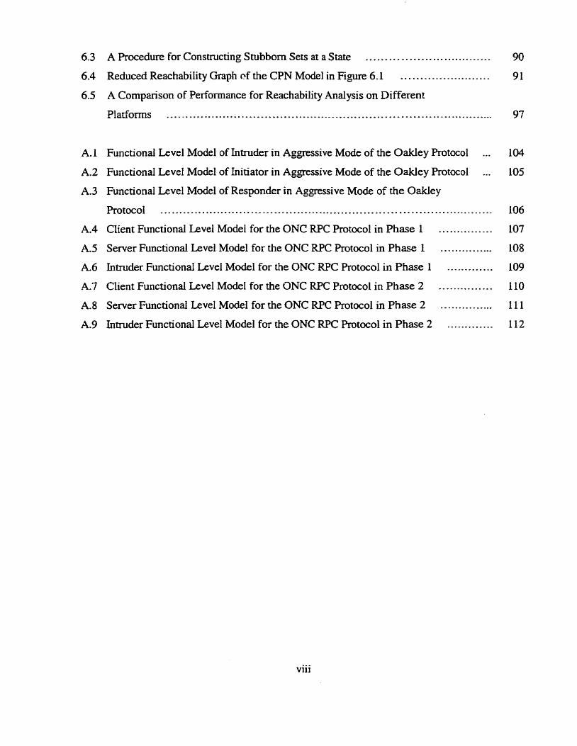
List of Figures
List of Tables
Chapter 1 Introduction
................ 1.1 Internet Security *
1.2 A Survey on Cryptographie Algorithm ..................... ... ......................... A
1 -3 Cryptographie Protocol Analysis ........................................................... 3
1.4 Thesis Outline ....................................... I ......................................... 6
Chapter 2 F o r d Methods for Protocol Analysis 9
..................................................................................... 2.1 BAN Logic 10
............................................................................. 2.2 Algebraic Method 12
..................................................... .................... 2.3 S tate Machines ,., 13
2.4 PetriNets ....................................................................................... 14
Chapter 3 Coloured Petri Nets
...................................................................... 3.1 Background Know ledge
.................................................................. 3 -2 Formal Definition of CPNs
................................. ...................... 3 -3 Graphicd Representation of CPNs .. .................................. ................... 3.4 Properties of Coloured Petri Nets ....
................................................................................ 3.4.1 Reac habili ty
................................................... ....................... 3 .4.2 Boundedness ,...
3.4.3 Liveness ................................................................................... ................................................................. ............ 3 -5 Petri Net Objects ;
..................................................... ...... 3 . 5. 1 The Representation of PNOs : 3.5.2 EntityLevel ................................................................................
.......................................................................... 3.5.3 Functional Level
.......................... 3.6 The Method for Protom1 Analysis Using CPN ............. ,... 26
................................. ................... 3.6.1 Reachability Analysis ... ... .... 26
...................................... 3.6.2 Matrix Equation Solution .................. ..... 28
Chapter 4 Protocol Modehg and Analysis in Petri Net Modeler
...............*..... .....................*..... 4.1 An Introduction to Petri Net Modeler ....
4.1.1 An Overview .............................................................................. ............... 4.1.2 Defini tion and General Rules of Using Colour and Pattern Index
..................................... 4.1.3 Features of the PNM .. ........... ................................. 4.2 The O A K E Y Protocol - an Example .... .............
......................................... 4.2.1 The Specification of the OAKLEY Protocol
............ 4.2.2 Modeling of the OAKLEY Protocol and Intnider Mode1 in the PNM
................. .......y 4.2.3 Automated Analysis of the O AKLEY Rotocol in PNM ..
............................................... 4.2.4 Modification of the OAKLEY Protocol
Chapter 5 Automated Security Analysis of ONC RPC Protocol
.................................. .......* 5.1 The Specification of the ONC RPC Protocol ... ........................ .......................... 5.2 Modeling of the ONC RPC Protocol ...
a 5.2.1 ModelingofPhase1 ........................................... ...................................................................... 5.2.2 Modeling of Phase 2
................................... 5.3 Analysis and Modification of the ONC RPC Protocol
................................. .................................. 5.3.1 Analysis of Phase 1 .. ...*.......................*........ ...*..............*...... 5.3.2 Modification of Phase 1 ...
...................................................................... . 5.3.3 Analysis of Phase 2
................................ ........................... 5.3.4 Modification of Phase 2 ... 5.3.4.1 Method 1 ...............................................................................
............................................................................... 5.3 A.2 Method 2
..................................................................................... 5.4 ConcIusion
Chapter 6 Eniciency in Rotocol Analysis 83
.......................................................... 6.1 Exhaustive Reachability Analysis 83
6.2 Reduced Reachability Andysis . . . . . . - -. . . . . -. . . . . . . . . . . . . . . . . . . . . . . . . . . . . . . . . -. . . - - -. . . . . 86
6.2-1 Idea of Stubborn Sets . . . . . . . . . . - . . . . . - . . - .. - - -. - - - -. . . . . . . . . . . - - . -. -. . . . . . . . . . . - . - . . 86
6.2.2 Constnicting Stubbom Sets . . . . . . - . . - . . . . . . . . . . . . -. . . . . . . . ... . . . . . . . . . . . . . . . . - - . - . 87
6.2.3 Reachability Analysis Using Stubbom the Set Method . . . . . . - -. , . . . . . . . . . . . . . . . . . .. 90
6.3 Cornparison of Efficiency of Reachability Andysis on Different Platforms ... . . . . . . 95
Chapter 7 Conclusion 98
7.1 Discussion . . - . . . . . . . . . . . . . . . . - - . . . . . . . . . - . . . . . . . . . . .. . - -. - . . . . . . . . . . . . . . . . . . . . . . . . . . . . . .. . - . . . . 98
7.2 Con~butions . . . . . - . . . . . . . . . . . . . . . - . . . . . . . -. . . . . . - -. . . . .. - - - . . . . . . . - *. . . . - . . . . . . . . . . . . . . . . 100
7.3 Funire Work ......,.. ...... .....-...-...-...-...-.. ............................... 101
Appendix A
Some examples of the Petri Net Modeler Screen Interfaœ
Appendix B
The ResuIts of Reduced Reachability Analysis for the OAKLEY Protocol and the
ONC RPC Protocol 113
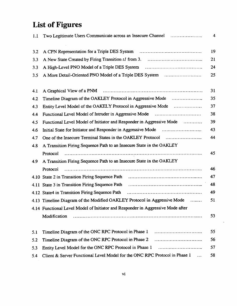
List of Figures ................... 1.1 Two Legitimate Usen Communicate across an Insecure Channel ..
3.2 A CPN Representation for a Triple DES S ystem ........................................
3 -3 A New S tate Created by Finng Transition t l from 3 ..................................... ..................................... 3.3 A High-Level PNO Model of a Triple DES System
..................... 3.5 A More Detail-Onented PNO Mode1 of a Triple DES System ...
............................................................... A Graphicd View of a PNM
.................... Timeline Diagram of the OAKLEY Protocol in Aggressive Mode
.................. Entity Level Model of the OAKELY Protocol in Aggressive Mode
... .......... ........... Functional Level Mode1 of Intnider in Aggressive Mode ... ...
............ Functional Level Model of Initiator and Responder in Aggressive Mode
.......................... Initial S taie for Ini tiator and Responder in Aggressive Mode
........................ One of the hsecure Terminal States in the OAKLEY Protocol
A Transition Firing Sequence Path to an Insecure State in the OAKLEY
.................................................. Protocol ................................... ...t 4.9 A Transition Firing Sequence Path to an Insecure State in the 0-Y
.................................................................................. Protocol
................................................ 4.10 State 2 in Transition Finng Sequence Path
................................................. 4.1 1 State 3 in Transition F i n g Sequence Path
................................................ 4.12 State4 in Transition Firing Sequence Path
........ 4.13 Timeline Diagram of the Modified OAKLEY Rotocol in Aggressive Mode
4.14 Functional Level Model of Initiator and Responder in Aggressive Mode aher
................................................................................... Modification
................... ....... 5.1 Timeline Diagram of the ONC RPC Protocol in Phase 1 ...
............................... 5.2 Timeline Diagram of the ONC W C Protocol in Phase 2
............................. 5.3 Entity Level Model for the ONC RPC Rotocol in Phase 1
5.4 Client & Semer Functional Level Model for the ONC W C Protocol in Phase 1 ...

5.5 Intruder Functional Level Mode1 for the ONC RPC Protocol in Phase 1 ..............
............................. 5.6 Entity Level Model for the ONC RPC Protocol in Phase 2
5.7 Client & Server Functiond Level Mode1 for the ONC W C Protocoi in Phase 2 ...
5.8 IntxuderFunctional LeveI Mode1 fortheONC RPCProtocolin Phase2 .............
5.9 Initial State of Client & Server in Phase 1 of the ONC RPC Protocol ................ 5.10 Insecure Terminai S tate Found in Phase 1 of the ONC RPC Protocol ................ 5.1 1 A Transition Firing Sequence Path to Insecure Terminal State in Phase 1
...................................... of the ONC RPC Protocol ......................... .. 5.12 State 1 in Transition F i n g Sequence Path in Phase I of the ONC RPC Protocol ...
5.13 State 2 in Transition Firing Sequence Path in Phase I of the ONC RPC Protocol ... 5.14 Timeline D i a m for the ONC RPC Protocol in Phase 1 after Modification ........ 5.15 Client & Server Functiond LeveI Model in Phase 1 of the ONC RPC Protocol
...........*............*..*... ........................*.......*....... after Modification ... 5.16 Case4 Initial State for Intnider of the ONC RPC Protocol in Phase 2 ................. 5.17 Case4 Initial State for Client & Server of the ONC RPC Protoc01 in Phase 2 ....... 5.18 Insecure Terminal State F~und in Phase 2 of the ONC RPC Protocol for Case4 ....
5.19 State 1 of Transition Firing Sequence Path in Phase 2 of the ONC RPC Protocol
....................................................................................... for Case4
5.20 State 2 of Transition Firing Sequence Path in Phase 2 of the ONC RPC Protocol
....................................................................................... for Case4
5.21 Transition Firing Sequence Path to an Insecure Terminal State in Phase 2 of the
............................................................... ONC RPC Protocol for case4
5.22 Functional Level Model of Server in Phase 2 of the ONC RPC Protocol after
............................................................... Modification Using Method I
5.23 Timeline Diagram of Modified the ONC RPC Protocol in Phase 2 Using
....................................................................................... Method 2
5.24 Functional Level Mode1 of CIient & Server in Phase 2 of the ONC W C Protocol
........................................ after Modification Using Method 2 ... ...........
................................................................... 6.1 A Simple Petri Net Model
..................... 6.2 Full Reachability Graph of the Petri Net Mode1 in Figure 6.1 ....
vii
A Procedure for Constnicting Stubborn Sets at a State .................................
Reduced Reachability Graph of the CPN Mode1 in Figure 6.1 ........................
A Cornparison of Performance for Reachability Analysis on Different
Platforms ........................mi...............
... Functional Level Model of hiruder in Aggressive Mode of the Oakley Protocol
... Functiond Level Model of Initiator in Aggressive Mode of the Oakley Protocol
Functional Level Model of Responder in Aggressive Mode of the Oakley
Protocol ........................................................................................ Client Functionai Level Mode1 for the ONC RPC Protocol in Phase I ...............
Server Functional Level Mode1 for the ONC W C Protocol in Phase 1 ............... Intruder FunctionaI Level Mode1 for the ONC RPC Protocol in Phase 1 .............
Client Functional Level Mode1 for the ONC W C Protocol in Phase 2 ...............
............... Server Functional Level Model for the ONC RPC Protocol in Phase 2
9 Intruder Functional Level Mode1 for the ONC W C Protocol in Phase 2 ............. 112
... Vll l
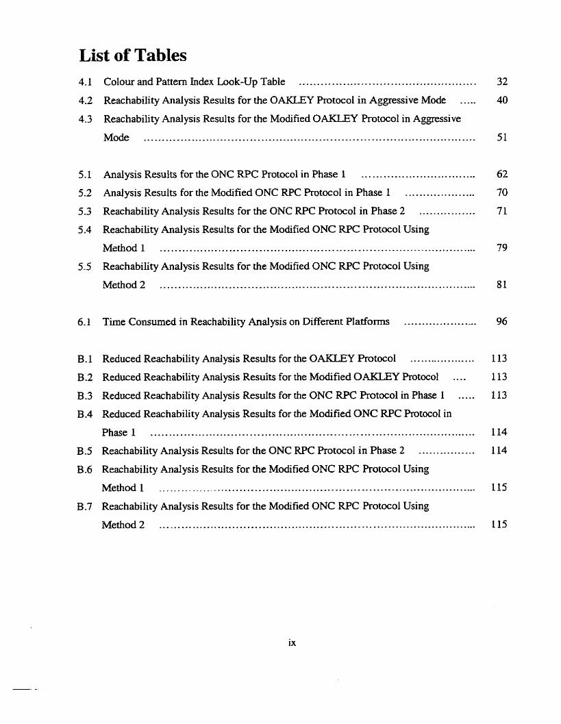
List of Tables 4.1 Colour and Pattern Index Look-Up Table ................................................
4.2 Reachability Analysis Results for the OAKLEY Protocol in Aggressive Mode .....
4.3 Reachability Analysis Results for the Modified OAKLEY Protocol in Agpssive
........................................................................................... Mode
5.1 Analysis Results for the ONC RPC Protocol in Phase 1 ..................... .. ........ 5.2 Analysis Results for the Modified ONC RPC ProtocoI in Phase 1 .... ... .............
5.3 Reachability Andysis Results for the ONC RPC Protocol in Phase 2 ................
5.4 Reachability Analysis Resulis for the Modified ONC RPC Protocol Using
....................................................................................... Mcthod 1
5.5 Reachability Analysis Results for the Modified ONC RPC Protocol Using
....................................................................................... Method 2
6 Time Consumed in Reachability Analysis on Different Platfoms .....................
B . 1 Reduced Reachability Analysis Results for the OAKLEY Protoc01 ...................
B -2 Reduced Reachability Analysis Resuits for the Modified OAKLEY Protocol ....
B -3 Reduced Reachability Analysis Results for the ONC RPC Rotocol in Phase 1 .....
B.4 Reduced Reachability Analysis Results for the Modified ONC RPC Protocol in
......................................................................................... Phase 1
B.5 Reachability Analysis Results for the ONC RPC Protocol in Phase 2 ................
B.6 Reachability Analysis Results for the Modified ONC RPC Protocol Using
Method I .......................................................................................
B.7 Reachability Analysis Results for the Modified ONC W C Rotocol Using
....................................................................................... Method 2
Chapter 1
Introduction
1.1 Internet Security
The Intemet was developed in 1965 for academic and rnilitary use. Three decades later, it is
regarded as the "information superhighway" with more and more computer networks and users
be involved in it. In essence, the open design of the Internet, geared towards die ease of
communication and rapid development, has led to a severe lax in system security. As new
developments and applications of information technology emerge, so do the possibilities of
hostile attacks on local area networks (LANs) and wide area networks (WANs). Therefore, the
securîty aspects of the Internet must be carefully scrutinized [2][72]. The three fundamental
objectives of security are: privacy or confidentiality, data integrity, and authentication
[15] [37] 1571 [63].
Confidentiality stipulates that the data in a computer system, as well as the data
msmitted between computer systems, be revealed only to authorized individuals. Secrecy is a
term synonyrnous with confidentiality and privacy. There are numerous approaches to providing
confidentiality, ranging from physical protection to mathematical algorithms which render data
unintelligible.
Data integrity is a service which address the unauthorized alteration of data, To assure
data integrity, one must have the ability to detect data manipulation by unauthorized parties. Data
manipulation includes such things as insertion, deletion, and substitution.
Authentication is the technique by which a process verifies that its communication
p m e r is who it is supposed to be and not an impostor and information delivered over a channel
should be authenticated as to origin. This aspect of cryptography is usually subdivided into two
major classes: en tity authentication and data origin authentication. The latter implicitly provides
data integrity.
1.2 A Survey on Cryptographic Algorithm
Cryptographic aigorithm are incorporated into cryptographic protocois to achieve the above
secwïty issues. Cryptography is the use of transformarions of data infended to m a k the data
useless to one's opponenrs 1151. A cryptographic system, or simply a cryptosystem, is an
implementation of a given algorithm that performs such transformations.
The essentid technology underlying virtually d l automated network and cornputer
security applications is encryption. Two fundamentai approaches are in use: conventional
encryption, also known as symmetnc key cryptosystem, and public-key encryption. aiso known
as asymmetrïc key cryptosystem.
Let { E , : e c K} be a set of encryption nansformations, and let {D, : d E K} be the set of
comsponding decryption transformations, where K is the key space. In a symmeûic key
cryptosystem, for each associated encryption/decryption key pair (e,d), it is computationally
"easy" to detemine d knowing only e, and to determine e from d. A cryptosystem is defined to
be cornputationally secure if the best algorithm for breaking it requires specified very large
number of operations. An unconditionally secure cryptosystem may be defined to be a
cryptosystem which cannot be broken even with infinite computational resources. The
encryption and decsrption key in most practical symmetric key cryptosystems are identical. The
key e is used by a pair of principals to encrypt and decrypt messages to and from each other.
Since the plaintext cannot be derived from the ciphertext without knowledge of the key, the
ciphertext c m be sent over public networks such as the Intemet. To ensure secunty of
communication in this approach the key is kept secret between the communicating entities.
Modem day symmetnc key aigorithms are principally block ciphers and Stream ciphers. Block
ciphen will encrypt a block of (typically 64 or 128) plaintext bits at a Ume. The best-known
block cipher is the ubiquitous Data Encryption Standard, universally refemd to as DES [22].
The basic idea of Stream is to generate a keystream and use it to encrypt a plaintext string.
In contrast, there is no shared secret between communication entities in an asyrnrnetric
key cryptosystem. Different keys are applied for encryption and decryption separately. The
public key e is for encryption and could be made public by publishing it in a directory. The
pnvate key d is for decryption and must only be known by the entity who decrypts ciphertext
using that key. Data encrypted with the public key c m be decrypted with the associated private
key and vice versa. The premise of this system is based on that given encryption key e, it is
computationally infeasible to determine the corresponding decryption key d. The most
commonly used asymmetric key cryptosystem is Rivest-Shamir-Adleman - RSA [55].
Cryptanalysis is the study and practice of breaking ciphers by determining a security key
and consequently its corresponding plaintext either from the ciphertext or from collections of
plaintext-ciphertext pairs. For an extensive discussion of the various issues in cryptography, the
reader is encouraged to review [14] [15] [34] [37] [57] [62] [63].
1.3 Cryptographie Protocol Analysis
A cryptographic protocol is a distributed algorithm defmed by a sequence of steps precisely
specifying the actions required of two or more entities to achieve a specific securïty objective. In
cryptographic protocols part of at Ieast one message is encrypted. Cryptographic protocols are
1
used to establish secure communication over insecure open networks and distributed systems.
These protocols use cryptographic algorithm to achieve securïty goals such as confidentiality,
auihentication of entities and s e ~ c e s , message integrity, non-repudiation, order and timeliness
of the messages, and distribution of cryptographic keys- Unfortunately, open networks and
distributed systerns are vulnerable to hostile intniders who may try to subvert the protocol design
goals.
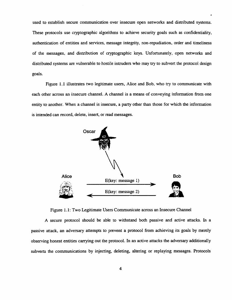
Figure 1.1 illustrates two legitimate users, Alice and Bob, who try to cornmunicate with
each other across an insecure channel. A channel is a means of conveying information from one
entity to another. When a channel is insecure, a party other than those for which the information
is intended c m record, delete, insert, or read messages.
Alice Bob
Figure 1.1 : Two Legitimate Users Communicate across an Insecure Channel
A secure protocol should be able to withstand both passive and active attacks. In a
passive attack, an adversary attempts to prevent a protocol from achieving its goals by merely
observing honest entities carrying out the protocol. In an active attacks the adversary additionally
subverts the communications by injecting, deleting, altering or replaying messages. Protocob
may fail for a number of reasons, including:
Weakness in a particular cryptographie primitive which may be amplified by the protocol.
Claimed or assumed security guarantees which are overstated or not clearly understood.
The oversight of some principle applicable to a broad class of primitives such as encsrption.
Since typically there are only a smdl number of messages invoived in cryptographic
protocols, one would think that successfully designing and implementing one should be
straightforwad However, they are notoriously error-prone due to the unpredictable capabilities
of an innuder. Cryptographic dgorithms are incorporated into cryptographic protocols.
However, the security of the underlying algorithms doesn't guarantee a protocol meets its
security objectives. The flaws might be related to the protocol design. It is not surprising that
- there have been several examples of nyptographic protocols that were published, believed to be
sound, and later shown to have security flaws [42][45]. For instance, a flaw in the Needharn-
Schroeder key distribution protocol proposed in 1978 1461 was found by Denning and Sacco 1131
in 1981 and another flaw was found by Lowe [33] in 1995. Widespread ùnpiementation of a
protocol with unknown flaws may lead to hannfu1 consequences.
In this thesis, the underlying cryptographic algorithms used in cryptographic protocols
are assumed to be secure so that protocol analysis c m be separated from algorithm andysis. This
dlows us to focus on protocoi analysis.
After the discovery of flaws in a protocol, the fiaws are often corrected or approaches are
adopted to avoid using the reasoning of the flawed protocols. These facts increasingly prompted
research into the development of several different methods for detecting protocoi failures, as well
as systematic andysis approaches to designing secure protocols.
Methods for evaluating the security of protocols are still under development. These
methods may be divided into two basic classes: informal and formal. Fomd methods have been
proved to be more effective than informal ones 1701. Naturai language and timeline description
are examples of informal methods. Fonnal methods include state machines [8], BAN logic [IO],
Algebra 1381, as well as Coloured Petri Nets [7]. These approaches are reviewed by [17], 1351,
and [56]. Chapter 2 discusses the feanires of various approaches used in protocol analysis. The
approach adopted in this thesis to automated analysis of protocols is based on Coloured Petri
Nets, due to its facility for graphitai representation and precise specification,
In Chapter 1, the concept of Internet security is introduced. Confidentiality, integrity, and
authentication are three hindamental objectives of securi ty. Cryptographic protocols are used to
secure the applications and data transmission over the Intemet. Cryptographic algorithms are
incorporated into cryptographic protocols to achieve the security issues. Two fundamental
approaches are in use: conventional encryption and public-key encryption. Although their
underlying algorithms rnay be secure, cryptographic protocols may contain flaws related to
protocol design. The main purpose of this thesis is to model and andyze protocols based on
Coloured Petri Net (CPN) methodology.
Different methods can be used in protocol analysis. Formal rnethods include state
machines [8], BAN logic [IO], AIgebra [38], and Coloured Petn Nets[7]. It seems unlikely that
any of hem suffices as the complete, all-encompassing solution for the analysis of protocols.
Chapter 2 gives a review of these formal methods which are found in the current literature.
Since we model and analne the protocols based on the CPN theory, sorne background on
it is given out in Chapter 3. Formal definition and graphical representation of CPNs are defined.
Properties of CPNs such as reachability, boundedness, and liveness are described. Petri Net
Objects (PNOs) and the hierarchical concept are intmduced. Finally, two methods used for
protocol analysis in this thesis, reachability analysis and matrix equation solution, are presented.
In chapter 4, an overview of the Peû-i Net Modeler (PNM) [20][21], a graphitai
integrated Petri Net simulation tool, is represented. It is used in this thesis for automatically
modeling and analyzing protocols. Generai niles of using colour and pattern are defineci. As an
example, the detrùled automated analysis of the OAKLEY protocol [50] is conducted in the
PNM. The results of the analysis are tabulated. By examining the teminal states within the
reachability graph obtained from the reachability search, we can determine whether the protocol
violates its security objectives. If there exist insecure terminal states, the security objectives of
the protocol may be subverted. The matrix equation solution cm îhen be usedfo show detailed
information of how to reach the insecure states. Moreover, we propose schemes to modiQ the
fiawed protocol.
In Chapter 5, the ONC W C protocol [12] is explored using the automated analysis
methodology presented in the previous chapter. Both phases are modeled and analyzed. The
results of analysis are listed in the tables. Different schemes are described for fixing the flawed
protocol.
In Chapter 6, fmtiy, the exhaustive reachability search algorithm is described. To solve
the space explosion problem and consequently Save execution time during the search, a reduced
reachability search based on stubborn set technology is introduced. For cornparison, we conduct
the reachability search for the OAKLEY protocol and the ONC RPC protocol again in this
reduced fashion- From the tabulsted andysis results we c m see that the efficiency of protocol
analysis using reduced reachability search is significantly irnproved. In an experiment, we
perform reachability anal ysis for the OAKIEY protocol and the ONC RPC protocol respective1 y
on Unix, Windows, and Linux for testing the efficiency of protocol analysis on different
platforms.
Chapter 7 closes the thesis with a review of the results obtained d o n g with some
conclusions about the methodology. A description of the contributions of the thesis is presented.
The OAKLEY and ONC RPC protocols are modeled and anaiyzed based on exhaustive and
stubborn set reachability andysis which are implemented aqd integrated into the PNM in tfi is
thesis, Some flaws are discovered with an intruder mode1. Schemes for modification are
proposed to fix the flaws that are discussed. Suggestions are made for future work in this area as
well,
Chapter 2
Forma1 Methods for Protocol Analysis
The design of secure cryptographic protocols is a very complex and difficult process. Nowadays,
researchers are onented towards the use of fomal methods for the analysis and verification of
existing protocols. These methods have proved successful at discovering flaws in existing
protocols, sometimes previously unrecognized ones.
This chapter will highlight some of the formal metho& that can be employed in protocol
analysis. These formal methods include BAIV logic [IO], Algebra 1381, state machines 181, and
Petri Nets [7]. A cornparison is difficult since none of the approaches cover al1 security aspects
of a protocol. This is the reason Meadows stipulates in [35] that "it is unlikely that any formal
method will be able to mode1 al1 aspects of a cryptographic protocol, and thus it is unlikely that
any forrnal method will be able to detect or prevent al1 types of protocol flaws". However,
analyzed by the following fomal methods. a protocol can be proved to be able to withstand a
senes of specified attacks or meet its desired secuity objectives, although it cannot be proved to
be absoiutely error-free. More detailed descriptions and examples of these fomal methods can
be found in [17] [35] 1561.
The underlying cryptographic aigorithms are supposed to be secure, allowing a
concentrated effort on the analysis of the protocol from a security perspective. The purpose of
this thesis is to unveil potential flaws related to the protocol design bas& on Petri Net
methodology .
A formal logic model, called BAN logic, presented by Burrows, Abadi, and Needham 1101 has
been widely used for the analysis of authentication protocols, which is a function of integrity and
freshness, and uses logical rules to trace both of those attributes through the protocol. In this
style of analysis a set of participants' final beliefs is generated from a set of initial assumptions
and the protocol messages. If these beliefs satisfy the goal of the protocol, then the protocol is
validated.
BAN logic is a modal logic with specialized staternents and symbols used to identify the
particula. objects common within authentication protocols. Objects from the set of principals are
given symbols P and Q; those from the set of messages are called X; those from the set of
encryption keys are called K. Sorne of the essential constructs wouid be described as follows:
P believes X- P believes the message X to be eue. This construct is central to the logic.
P sees X - P can read and repeat (possibly after doing some decryption) the message sent by
someone.
P said X - P at sorne time sent the message X.
P A Q - P and Q are using the shared private key K for communication.
{X ), - the message X is encrypted under the shared private key K.
Several postulates or d e s of inference are defined using the constnicts described above.
From the five classes of postulates given in [IO], the following is an example of the message-
rneaning rule for shared keys:
PbeiievesQ< " tP,Psees {X},
P believes Q said X
10
This postdate States that if P believes thnt Q and P share a secret key K, and sees X encrypted
under key K, then P believes thut Q once said X [56]-.
There are tluee main stages for the analysis of a protocol using BAN logic. The first step
is to express the assumptions and goals as statements in a symbolic notation so that the logic can
proceed from a known state to one where it can ascertain whether the goals are in fact reached.
The second step is to transform the protocol steps into symbolic notation. Finally, a set of
deduction rules called postulates are applied. The postulates should lead frorn the assumptions,
via intermediate fornulas, to the authentication goals.
BAN logic has been a success. It has found flaws in several protocols, including
Needharn-Schroeder [46] and CClTT X.509 [Il]. It has uncovered redundancies in many
protocols, including Needharn-Schroeder [46], Kerberos [39], Otway-Rees [51], and CCITI'
X.509 [I 11. Many published papers use BAN logic to make claims about their protocol's security
c521r591.
However, since the publication of the BAN logic, several p a p a have reported problems
in its use for analysis of cryptographic protocols, including [61][64]. These reports reveal
limitations of the logic or misunderstanding and misuse of the logic. The most criticized points in
BAN logic are the fact that there is no complete semantics for the logic and the rnodeling of
freshness. The lack of complete semantics may lead to problems in modeling as some facts rnay
have an unclear meaning. It usually causes problems at the idealization step due to ambiguity and
vagueness, particularly where a message is idealized into a formula containing information not
present in the message itself. Regarding the modeling of freshness it is not possible - as is the
case in most modal logics - to distinguish between freshness of creation and freshness of receipt.
The abstract level of BAN logic models results in difficult to assess hypotheses and protocol
descriptions.
A successful approach called GNY logic was proposed by Gong, Needham, and Yaiialorn
[24] increasing the scope of BAN logic. GNY logic aims to analyze a protocol step-by-step,
rnaking explicit any assumptions required, and ctrawing conclusions about the final position it
attains. However, GNY logic addresses only authentication and is much more complicated and
elaborate than other methods as i t has many rules which have to lx considered at each stage [I l .
2.2 AIgebraic Method
The algebraic method models a protoc01 with a collection of mies for transforming and reducing
algebraic expressions representing messages. Representative meîhods in this category have been
proposed by Dolev and Yao [16], and Meadows [35] [36].
Dolev and Yao presented the basic model for describing each message in a protocol as a
string constructed from a finite set of symbols [16]. Under their model an intruder is in full
control of the network being able to read, rnodiQ, mate , and delete message; effectively, the
intruder is using the system being attacked as a machine to generate messages. The messages
follow some rewrite rules baseci, for example, on the properties of symmetric encryption. The
intruder's task is to discover a message that should have been secret. Thus, the protocol security
problem is transformed into search based on a term-rewrite system. This system was used to
develop analysis dgorithms for some restricted protocol classes.
The main drawbacks of the Dolev-Yao model are its failure to model the principals'
ability to remember state information between States, and the fact that it can only detect protocol
deficiencies. This approach is not automated and is restricted to analyzing a small number of
cryptographie protocols, especially those providing message encryption. Despite these
shortcomings, Dolev and Yao were the first to conceptualize the use of an active intruder for
protocol analysis which has k e n used by almost al1 other approaches.
In [38], Memtt broadens the applicability of the Dolev and Yao mode1 by carrying out
operations on an dgebraic model which captures the knowledge of the intruder. The new method
cm be used to reason about securîty properties beyond just secrecy. Based on Memtt's work,
Toussaint [66] derived the complete know ledge of cryptographic protocol participants. From the
states of knowledge of participants, associated states of beliefs can be fomed The probabilistic
properties of a given protocol are verified by using these different states [67]. Due to their great
deal of complexity, these approaches have not becorne very popular and thus their value as
andysis tool is limited [56].
2.3 State Machines
Meadow's NRL Protocol Analyzer [35][36] is a prototype verification tool, written in Rolog,
that can be used to assist either in the verification of security properties of cryptographic
protocols or in the detection of security flaws. The NRL model takes the same approach as the
term-rewrite model of Dolev-Yao [16]. The main ciifference berween the two rnodels is that the
Dolev-Yao model mats a protocol as a machine for producing messages, while the NRL
Protocol Analyzer mats a protocol as a machine for producing not only messages, but also
beliefs and events. In the NRL model each protocol participant possesses a set of beliefs. These
kliefs are created or modified as the result of receiving messages made up of words, while
messages are sent depending upon both beliefs and messages received. Events represent the state
transitions in which new words are generated and beliefs are modified. Thus an intruder who
controls the dissemination of messages can use the protocol to produce words, beliefs, and
events,
The NRL Protocol Analyzer, in common with the Interrogator mode1 1401 [41] uses a
backward search strategy to constnict a path from a specified insecure state to an initial state.
The main difference between the NRL model and the Interrogator stems from their end goals: the
NRL model aims to prove that a protocol is secure while the Interrogator is designed to search
for ways to achieve insecure states without guaranteeing that the protoc01 is secure if the search
fails. However, unlike the interrogator model, the NRL Analyzer can constnict a single path
using an arbitrary number of protocol rounds thereby working in an infinite state space. This
approach dlows the NRL Analyzer to discover attacks based on a combination of protocol runs.
The NRL Protocol Analyzer has been used successfdly to locate a series of previously
unknown flaws in a number of protocols [9] [60], and to demonstrate flaws that were already
h o w n in the iiterature [29]. The main drawback of the cui-rent implementation is the fact that to
keep the state space workable some drastic simplimng assumptions are required. In addition, as
with most rule-rewrite systems, it is not clear how weil the system scdes as more complicated
algorithms will need to be expressed using an ever increasing set of niles. Another source of
difficulty in using the NRL Protocol Anaiyzer lies in the generation of lemmas stating that
infinite classes of states are unreachable: these have to be proved by hand.
Petri Nets
The formal analysis methods descrïbed in the previous sections suffer from either their
complexity or their lack of graphical representation. Petri Nets c m be used to model concurrent,
disûibuted, or parallei systems and provide fiexibility nor found in other methods. Introduced by
C. A. Petri [53] in 1962, Petri Nets have been used as a fonnal method for protocol analysis. An
important feature of Petri Nets is its ability for precise graphical representation of the protocols,
which provides visual analysis. This feature makes complex protocols more understandable so
that it becornes easier to find flaws.
As a speciai class of Petri Nets, Coloured Petri Nets (CPNs) [26][27][28] incorporate
both data structures and hierarchical decomposition without comprornising the properties of
ordinary Petri Nets. CPNs form the basis for the protocol specification methodology originated
from Behki and Tavares [6][7]. An innovation which stems from the methodology is the concept
of a high-level description of the protocol using "modified transition" which has become what is
now called a Petri Net Object (PNO).
Since then, a number of contributions have been made by others at Queen's University to
enhance the CPN based approach. A forrnal approach for specifymg and analyzing cryptographic
protocols is formulated by Nieh and Tavares [47][48]. Their work describes the msformation
of informal protocol descriptions into formal specifications in the fonn of Peûis Nets, The
methodology models a protocol at three description levels: entity, conceptual. and functional,
aliowing the analyst to choose an appropriate level of abstraction when examining a protocol. An
intnider with abilities to launch various attacks is modeled, Starting from an initial state, a
manual exhaustive forward execuüon of the protocol wouid consrntct a reachability tree which
could reveal whether any insecure terminal States are reached.
Morton and Tavares [43][443 proposed a modular approach that decomposes the Petri
Nets mode1 of a protocol into modules to break the analysis into smail parts, the sum of which
permits the evaluation of the overall security analysis. Their work dso defines the message
acceptance criteria for extraction of invalid intnider attacks. These concepts result in a smdler
search space and shorter execution tirne-
Doyle, Tavares, and Meijer [17][18][19] demonstrated an automated analysis of Petri
Nets models of cryptographie protocols. This evolution made protocol analysis feasible,
complete and relativety fast compared to manual approaches. However, since the methodology is
based on exhaustive search, sometimes the time consumed in executing automated analysis is
huge, especially for complex protocols.
To alleviate this problem, Zhao and Tavares [70][71] implemented the stubbom set
[54][68][69] search algorithm in the reachability analysis in C. In stubborn set search, instead of
firing every enabled transition iike in exhaustive search, it only selectively fires those enabled
transitions within the stubborn set. Execution time can be saved significantly by using this
method. It makes automated protocol analysis more pctical.
Basyouni and Tavares [4][5] applied matrix equation solution in their protocol analysis.
A user-fnendy graphical autornated Petri Net simulation tool called Petri Net Modeler (PNM)
was originated by Edwards, Tavares, and Meijer [20][21] and improved by Shao and Tavares
C581.
Other efforts on Petri Nets include Cryptographie Timed Petri Net (CTPN), a new type of
Petri Nets which was presented in 1321. Their work introduces a specification Ianguage called -
CTPN-language and provides an automated protocol analysis tool called CTPN-analyzer.
Another example of high-level Petri Nets king used in protocol analysis is Predicate-
Transition nets (PrT-nets) [23]. Instead of building custom software, Aura [3] adopted an
existing tool called PROD [25] for analysis of protocol specified in PrT-nets. The stubbom set
search algorithm is implemented in PROD to reduce the state space explosion.
Chapter 3
Coloured Petri Nets
3.1 Background Knowledge
Petri Nets were originally developed by C.A. Petri 1531 in 1962. and they were soon recognized
as k ing one of the most adequate and sound languages for description and analysis of
synchronization, communication and resource sharing between concurrent processes.
However, attempts to use Petri Nets in practice revealed two serious drawbacks 1271.
First of dl. there were no data concepts and hence the models often becarne excessively large,
because dl data manipulation had to be represented directly into the net structure (i-e., by means
of places and transitions). Secondy, there were no hierarchy concepts, and thus it was not
possible to build a large mode1 via a set of separate sub-models with well-defined interfaces.
As one of the most we11 known dialects of hi&-level Petri Nets, Coloured Petri Nets
(CPNs) were developed to remove two serious problems. CPNs incorporate both data stnicturïng
and hierarchicd decomposition without cornprornising the qualities of the original Petri Nets.
3.2 Formal Definition of CPNs
Coloured Petri Nets (CPNs) can be formdly defined as a 6-tuple CPN = (P, T, A? C , S, . R) in
which:
p = {p,, p,, p,, .... p, } is a finite set of places, where m is the number of places in the CPN
system.
T = ( t , , t2? t3 ,.... t,, 1 is a finite set of transitions, where n is the number of transitions in the
CPN system.
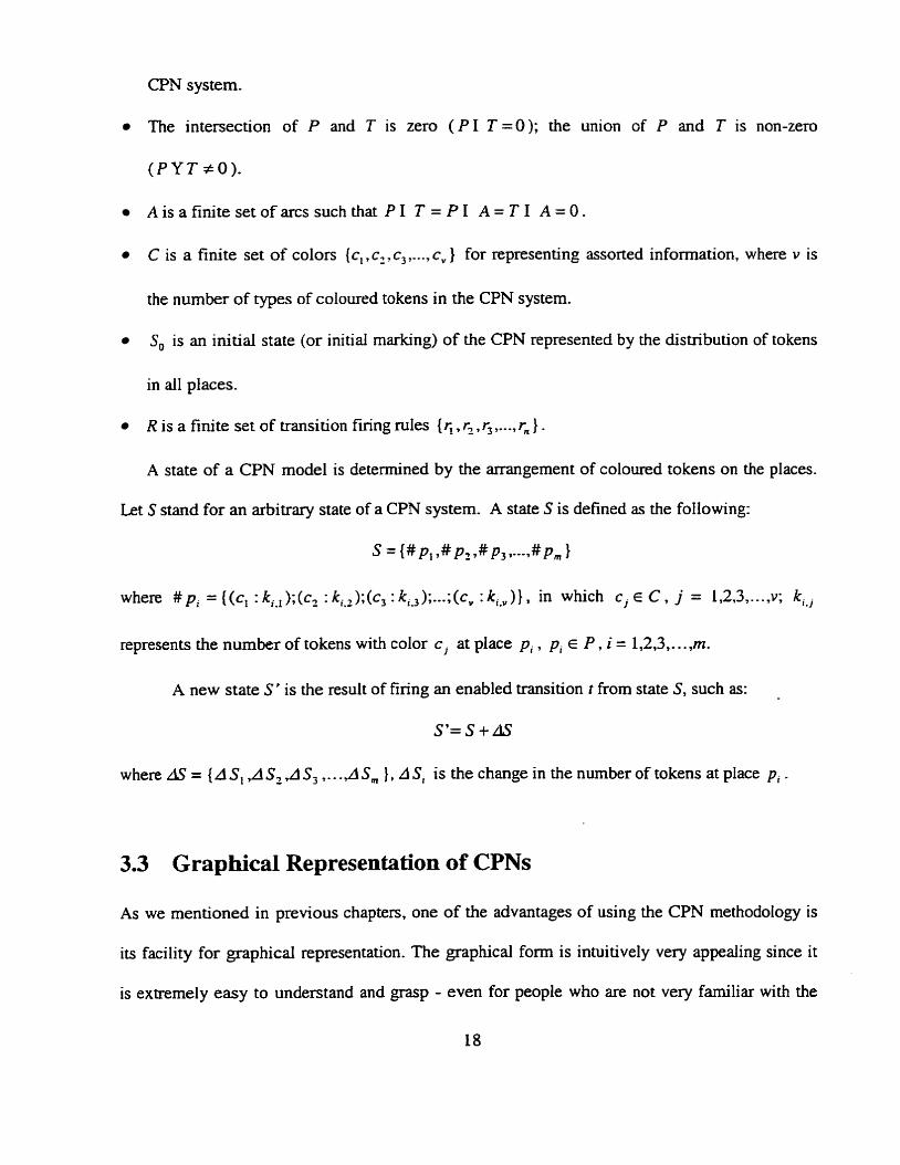
The intersection of P and T is zero ( P I T =O); the union of P and T is non-zero
(PYT $0)-
A is a finite set of arcs such that P 1 T = P 1 A = T 1 A = O.
C is a finite set of colors {c, , c,, c, ,..., c, } for representing assorted information. where v is
the number of types of coloured tokens in the CPN system.
S, is an initial state (or initial marking) of the CPN represented by the distribution of tokens
in al1 places.
R is a finite set of transition firing mles {r, . r,, r, ,..., r, } . A state of a CPN mode1 is deterrnined by the arrangement of coloured tokens on the places.
Let S stand for an arbitrary state of a CPN system. A state S is defined as the following:
s = {# p, ,#p2 ,#p3 >---.#pin 1
where #pi = {(c, : k,.J;(c2 : kiS2);(c3 : k i , J ) ; . - . ; (~ , : k i , J } > in which c j E C , j = 1,2,3 ,..., v; ki,j
A new state S' is the result of firing an enabled transition t from state S, such as:
S'= S +dS
w here AS = (A S, ,A S, ,A S , . . .,A Sm ) , A Si is the change in the nurnber of tokens at place p, .
3.3 Grap hical Representation of CPNs
As we mentioned in previous chapters, one of the advantages of using the CPN rnethodology is
its facility for graphicd representation. The graphical form is intuitively very appealing since it
is extremely easy to understand and grasp - even for people who are not very familiar with the
18
details of CPN. This is due to the fact that CPN diagrams resemble rnany of the drawings which
designers and engineers make while they construct and analyze a system.
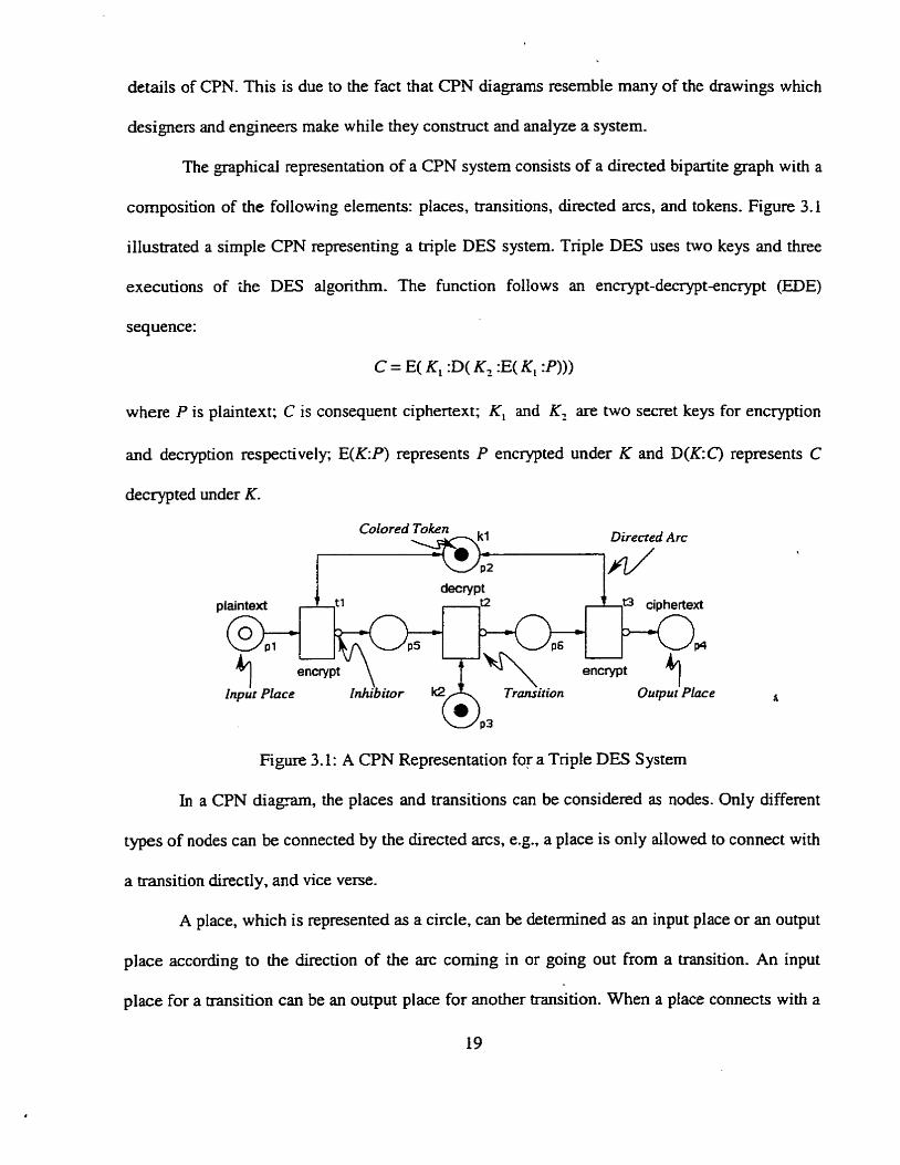
The pphicai representation of a CPN systern consists of a directed bipartite graph with a
composition of the following elements: places, transitions, directed arcs, and tokens. Figure 3.1
illustrated a simple CPN representing a triple DES system. Triple DES uses two keys and three
executions of the DES algorithm. The function follows an encrypt-decrypt-encrypt (EDE)
sequence:
C = E( K, :D( K2 :E(K, :Pl))
where P is plaintext; C is consequent ciphertext; K, and K, are two secret keys for encryption
and decryption respectively; E(K:P) represents P
decrypted under K.
Colored Token
encrypted under K and D(K: C) represents C
Direcred Arc
d=v Pt plaintext tl t2 * ciphertext
encrypt encrypt
Output Place d
P3
Figure 3.1: A CPN Representation for a Triple DES System
In a CPN diagram, the places and transitions can be considered as nodes. Only different
types of nodes c m be connected by the dîrected arcs, e.g., a place is only allowed to connect with
a transition directly, and vice verse.
A place, which is represented as a circle, c m be determined as an input place or an output
place according to the direction of the arc coming in or going out from a transition. An input
place for a transition can be an output place for another transition. When a place connects with a
transition in a bi-directional arc (also known as double headed arc or read only arc), it is both an
input place and an output place, like place p3 in Figure 3.1. This sort of place is usually
considered as a "database" for stonng constant information in a system. One cm relate input
places to pre-conditions and output places to postconditions of the events or acticns in the
system. A condition is a predicate or logical description of the state of the system.
Drawn as a coloured srnail circle, a coloured token is an "object" tiat resides in a place.
Coloured tokens cm be used to explicitly represent different data types. like the typed variables
in a high level programming language- Tokens may move around from one place to another
when an enabled transition fires. There is no restriction on the number of tokens that can reside
in a place.
A transition is drawn as a rectangular box. It represents events or actions of the system.
The occurrence of these events is controlled by the state of the system. Whether or not a
transition is enabled can be determined according to transition firing iules predefmed by the
system- A transition is enabIed if each of its input places has at Ieast as many tokens in it as arcs
from the place to the transition. When a transition is enabled, it may fire by removing tokens
from its input places and creating new tokens which are distributed to its output places. After
finng a transition, different arrangement of tokens on the places generates a new state. Let's
define the firing rule of transition tl in Figure 3.1 as the following:
input (remove) : (1 yellow token in place.pl, 1 green token in placep2)
output (place) : (1 green token in place p2 ,1 blue token in place p5)
After firing transition t1 according to the predefined firing rule, a new state is created as shown
in Figure 3.2.
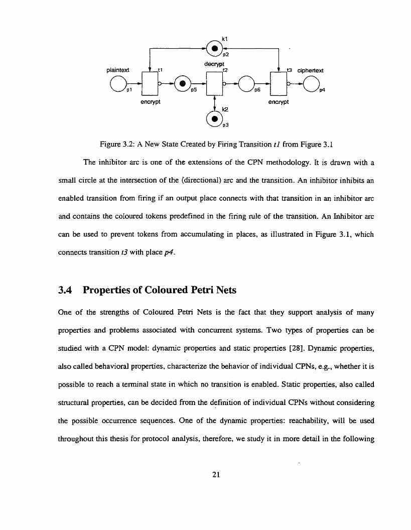
encrypt encrypt
Figure 3.2: A New State Created by Firing Transition t l from Figure 3.1
The inhibitor arc is one of the extensions of the CPN methodology. It is drawn with a
srnall circle at the intersection of the (directional) arc and the transition. An inhibitor inhibits an
enabled transition from firing if an ouvut place connects with that transition in an inhibitor arc
and contains the coloured tokens predefined in the firing mle of the transition. An Inhibitor arc
c m be used to prevent tokens from accumulating in places, as illustrated in Figure 3.1, which
connects transition r3 with place p4.
3.4 Properties of Coloured Petri Nets
One of the strengths of Coloured Petri Nets is the fact that they support analysis of many
properties and problems associated with concurrent systems. Two types of properties c m be
studied with a CPN model: dynarnic properties and static properties [28]. Dynarnic properties,
also called behavioral properties, characterize the behavior of individual CPNs, e-g., whether it is
possible to reach a terminal state in which no transition is enabled. Static properties, also called
structural properties, can be decided from the definition of individuai CPNs without considering
the possible occurrence sequences. One of the dynamic properties: reachability, will be used
throughout this thesis for protocol analysis, therefore, we study it in more detail in the following
sections.
3.4.1 Reachability
Reachability is a fundamental property for analyzing a CPN system. Defining an initial state S, ,
the firing of an enabled transition according to its firing rule will change the arrangement of
tokens on the places and cause the CPN system to enter a new state. A sequence of transition
firings will generate a senes of states. A state Si is said to be reachable from an initial state S, if
there exists a transition firing sequence path from S, to Si . Applying the reachability property to
our analysis of the CPN representation of protocols, we can discover al1 terminal states reachable
from a certain initial state. By examining these tenninal states, whether or not a protocol violates L
its securïty objectives c m be determined. A protocol is considered to be flawed if any insecure
terminal states reachable from an initial state can be found.
3.4.2 Boundedness
Intuitively, the boundedness property of a CPN system tells us how many tokens we c m have of
a particular color on a particula. place instance. A CPN system consists of the diagram and its
initial state S,, a place is said to be k-bounded if the number of tokens diat can reside on it will
never exceed a finite number k, regardless of the sequence of transition firings. A CPN system is
considered to be bounded if dl its places are bounded. In fact, a bounded CPN systern is a finite
state machine (FSM). Verimng the boundedness property ensures that tokens will not be
accumulated in a place without bound.
3.4.3 Liveness
The essence of the liveness property is that we would like a CPN system to keep running
infinitely under al1 operating conditions which indicates that the system wiIl never enter a
deadlock after an arbitrary transition firing sequence. A transition is live if for any finng
sequence of the CPN system, w e cm always find another firing sequence to make it fire again. If
dl the transitions in a CPN system are Iive, we Say that the CPN system is live. The liveness
property is especially important for cyciic protocols to ensure that each element of the protocol
keeps d i v e throughout a protoc01 run.
3.5 Petri Net Objects
One of the serious problems of an ordinary Petri Net model is its complexity increases greatly
when one attempts to model a large protocol. Morton [43] has examined the following methods
to alleviate this problem: hierarchical Petxi Nets, reentrant Nets, modular Petri Nets, and
modified transitions. The discussion in [43] leads to the conclusion that modified transitions are
the most appropriate for the specification and security analysis of cryptographie protocols.
Modified transitions, also known as super transitions. has been firstly introduced by Behki and
Tavares [6] and later renamed as Petri Net Objects (PNOs).
Petri Net Objects form the basis of the hierarchical modeling method for protocol
specification. The basic idea behind hierarchical nets is to ailow the modeler to constmct a large
mode1 by combining a number of small ones into a larger net. In order to develop and analyze
complex systems, one needs scnicturing and abstracting concepts that allow him to work with a
selected part of the mode1 without being distracted by the low-level details of the remaining
parts. Hierarchical nets provide such abstraction mechanisms. This is analogous to the situation
in which a programmer constmcts a large program from a set of modules and subroutines
without knowing the implementation of those components.
35.1 Representation of PNOs
We can impose object-oriented models on Petri Nets and put a subset of the Petri Net system in a
box called a Petri Net Object (PNO). A PNO is an extended definition of a transition and is
pphically represented as a rectangular box with a type of transition called ports which are
drawn on the inner edge of the box. A PNO interacts with the outside through its ports. i.e., for a
PNO, only the ports are visible to the external world. This structure makes a PNO a "black-box",
which suppresses intemal detailed information. PNOs make the protocol specification more
readable and consequently more understandable at various levels by abstracting details out. This
abstraction can be further used to define the specification of a sub-PNO recursively. This feature
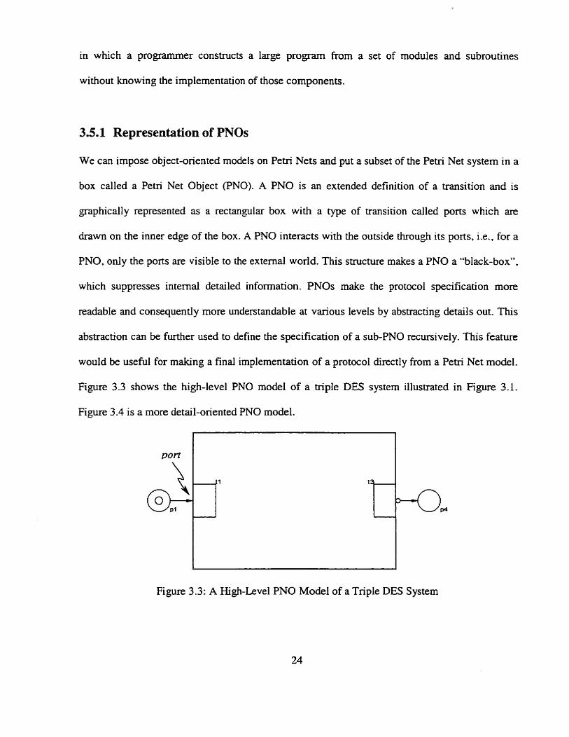
would be useful for making a final implementation of a protocol directly From a Petri Net model.
Figure 3.3 shows the hi&-level PNO model of a triple DES system illustrated in Figure 3.1.
Figure 3 -4 is a more detail-oriented PNO model.
Figure 3 -3: A Hi&-Level PNO Model of a Triple DES S ystem
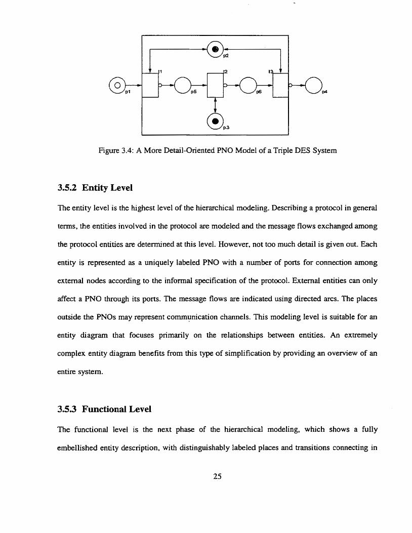
Figure 3.4: A More Detail-Oriented PNO Mode1 of a Triple DES System
3.5.2 Entity Level
The entity level is the highest level of the hierarchical modeling. Describing a protocol in general
terms, the entities involved in the protocol are modeied and the message flows exchanged arnong
the protocol entities are determined at this level. However, not too much detail is given out. Each
enùty is represented as a uniquely labeled PNO with a number of ports for connechon among
external nodes according to the informal specification of the protocol. Extemal entities can only
affect a PNO through its ports. The message flows are indicated using directed arcs. The places
outside the PNOs may represent communication channels. This rnodeling level is suitable for an
entity diagrarn that focuses primady on the relationships between entities. An extremely
complex entity diagram benefits from this type of simplification by providing an o v e ~ e w of an
entire system-
3.5.3 Functional Level
The functional level is the next phase of the hierarchical modeling, which shows a fully
embellished entity description, with distinguishably labeled places and transitions connecting in
directed arcs, as well as coioured tokens attached to places. The information received from
outside can be processed arnong transitions within the PNO according to the predefined
conditions. To mode1 the conditions, places are connected to transitions by directed arcs. The
conditions are set based on data types, represented by coloured tokens and required by
transitions. This modeling leveI is useful when detail information about an entity is required-
3.6 Methods for Protocol Analysis Using CPNs
Reachability search and matrix equation solution are two major Pen-i Nets analysis techniques
presented in this thesis in protocol analysis. Firstly, a reachability search is conducted on the
CPN mode1 of the protocoi from an initiai state to search out al1 terminal states. If there exist any
suspicious terminal states, the security objectives of the protocol may be subverted. A matrix
equation solution analysis then can be performed to detemine an occurrence sequence path from
the initial state to the suspicious terminai state to Iocate potentid flaws in the protoco1-
3.6.1 Reachability Analysis
The basic idea behind reachability andysis is to constmct a reachabihty graph (also called
reachability h-ee if it is not cyclic) through a reachability search. A reachability graph contains a
node for egch reachable state and an arc for each occuning binding element Obviously such a
graph may become very large, even for srnail CPNs. Due to the cycles, a net may have an infinite
number of reachable states and thus an infinite reachability graph. However, it c m be simplified
by omitting the cycle counten. The simplified net has a sirnilar behavior to the original one.
Hence reachability analysis of a CPN can be conducted by constmcting a reachability graph for
the simplified net.
A reachability p p h can be constructed by exhaustive search of al1 possible permutations
of transition firings from a specified initial state. The conectness of the protoc61 against a
specified intnider may be determined by verifyïng the result of the exhaustive state reachability
search.
Whether a transition fs activared c m be determined by its firing mle which consists of
pre-conditions and post-conditions, where pre-conditions are what determine if a transition is
enabled while post-conditions are what occur afiei an enabled transition has been fired. When a
transition fires, tokens in its input places will be removed new tokens will be created and
distributed to its output places according to the pre-conditions and post-conditions respectively.
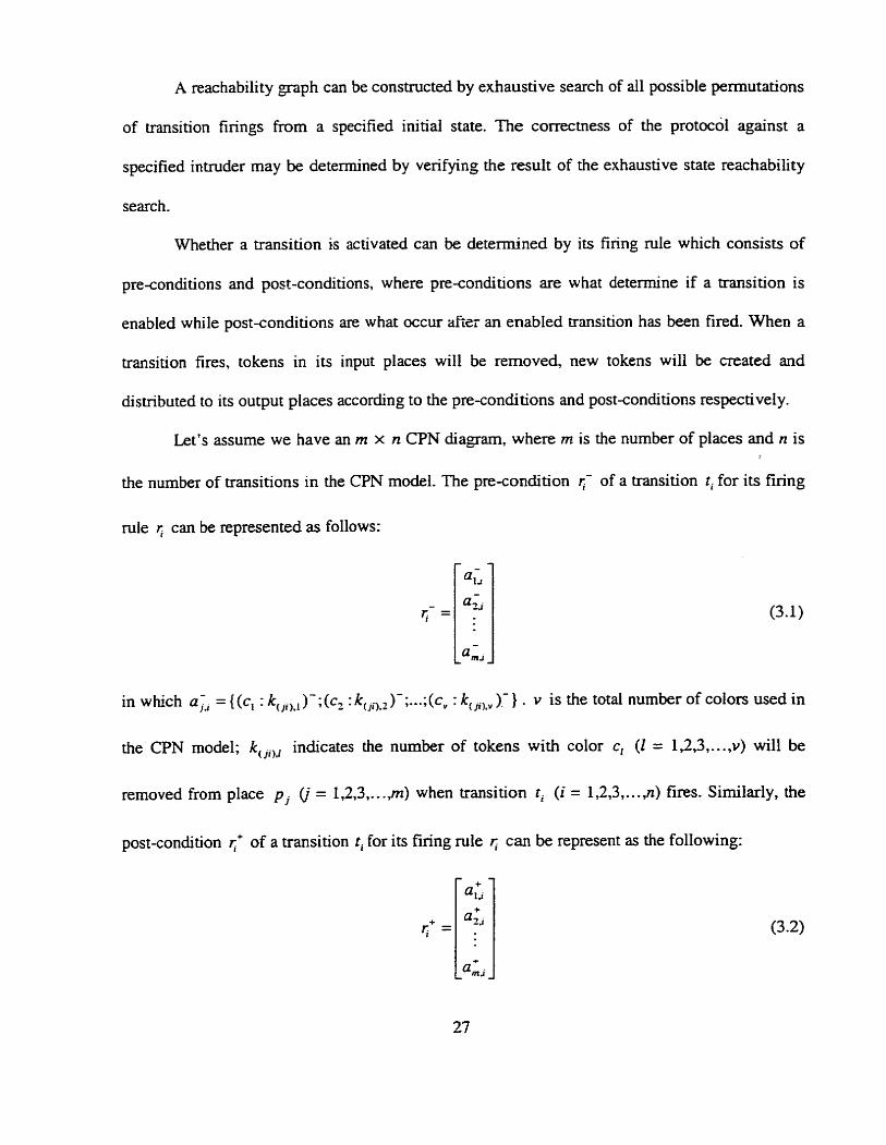
Let's assume we have an rn x n CPN diagam. where m is the number of places and n is
the number of transitions in the CPN model. The pre-condition 5- of a transition ti for its firing
rule r; can be represented as follows:
in which a, = { (c, : k,,ix, )- ; (c2 : k(,O,L )-; ...;( cV : kcJil,v ).- } . v is the total number of coiors used in
the CPN model; k, ,,, indicates the number of tokens with color c, (1 = 1,2,3,. . . ,v) will be
removed from place p (i = 1,2,3,. . .,m) when transition t, (i = 1,2,3 ,..., n) fires. Similady, the
post-condition r;' of a transition ti for its firing rule I; c m be represent as the following:
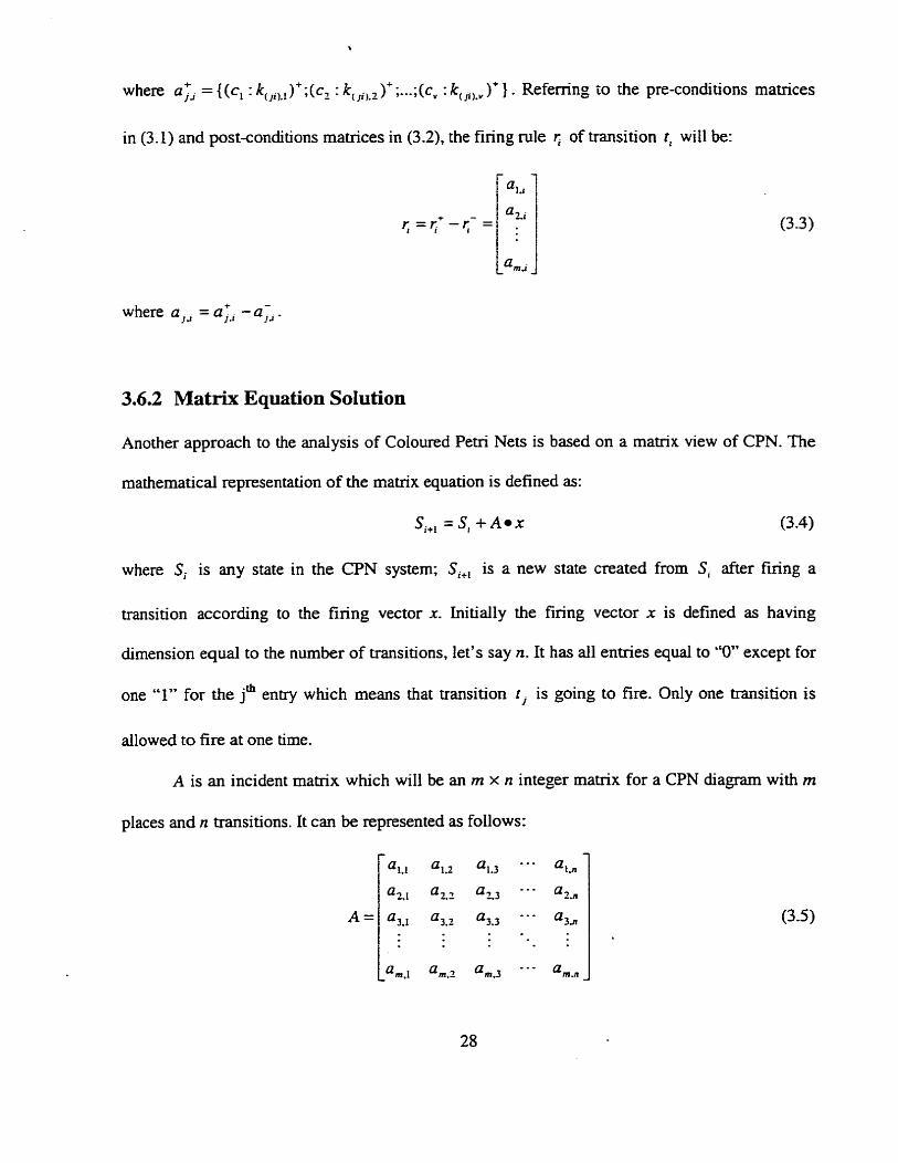
in (3.1) and post-conditions matrices in (3.2), the firing mle r; of transition tl will be:
where a,, = aIi - a , .
3.6.2 Mat& Equation Solution
Another approach to the analysis of Coioured Petri Nets is based on a matrix view of CPN. The
mathematical representation of the maû-ix equation is defined as:
Si+, = S, + A x (3.4)
where Si is any state in the CPN system; Si+, is a new state created from Si after f ~ n g a
transition according to the firing vector x. Initially the firing vector x is defined as having
dimension equal to the number of transitions, let's say n. It has d l entries equal to "O" except for
one "1" for the jm entry which means that transition t j is going to fire. Only one transition is
allowed to fire at one time.
A is an incident matrix which wiIl be an rn x n integer matrix for a CPN d i a m with m
places and n transitions. It cm be represented as follows:
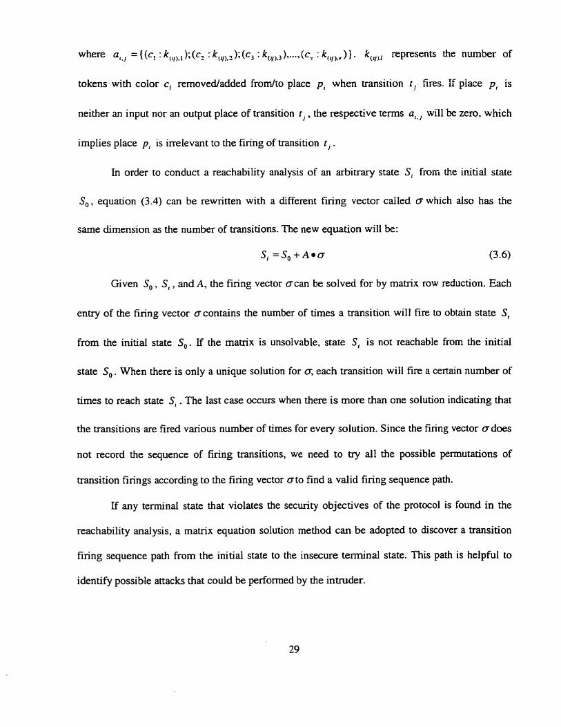
neither an input nor an output place of transition t, , the respective tems a,.j will be zero, which
implies place pi is inelevant to the firing of transition t j .
In order to conduct a reachability analysis of an arbitrary state Si from the initial state
S,, equation (3.4) can be rewrinen with a different fuing vector called o which also has the
same dimension as the number of transitions. The new equation will be:
Si =So+Aeo
Given S, , S i , and A, the firing vector ocan be solved for by matrix row reduction. Each
entry of the firing vector a contains the number of times a transition will fire to obtain state Si
from the initial state S,. if the matrix is unsolvable, state Si is not reachable fiom the initial
state So . When there is only a unique solution for o, each transition will fire a certain nurnber of
times to reach state S, . The last case occurs when there is more than one solution indicating that
the transitions are fired various number of tirnes for every solution. Since the finng vector odoes
not record the sequence of firing transitions, we need to ûy al1 the possible permutations of
transition firings according to the firing vector o to find a valid finng sequence path.
If any terminal state that violates the security objectives of the protocol is found in the
reachability analysis, a matrix equation solution rnethod can be adopted to discover a transition
finng sequence path from the initial state to the insecure terminal state. This path is helpful to
identifi possible attacks that could be performed by the intnider.
Chapter 4
Protocol Modeling and Analysis in Petri Net Modeler
4.1 An Introduction to Petri Net Modeler
The complexity of automated analysis for even a simple protocol is obvious. A pphical
protocol analysis tool is required to make the work less tedious and error-prone. A user-friendly
graphical integrated simulation tool, called Petri Net Modeler (PNM) which was originated by
Edwards, Tavares, and Meijer in [20][21] and improved by Shao and Tavares in [58] is used in
the analysis of protocols in this thesis. A reachability analysis function has been implemented
and integrated into the PNM in this thesis to make it capable of analyzing more complex
protocols.
4.1.1 An Ovemew
The Petri Net Modeler (PM is a Java application which was developed in Sun's standard Java
Development Kit (JDK). Java's Abstract Windows Toolkit (AWT), and later on the SWING
technology was adopted for creating a GUI interface. AH of its functionality c m be accessed by
the point-andclick of a mouse.
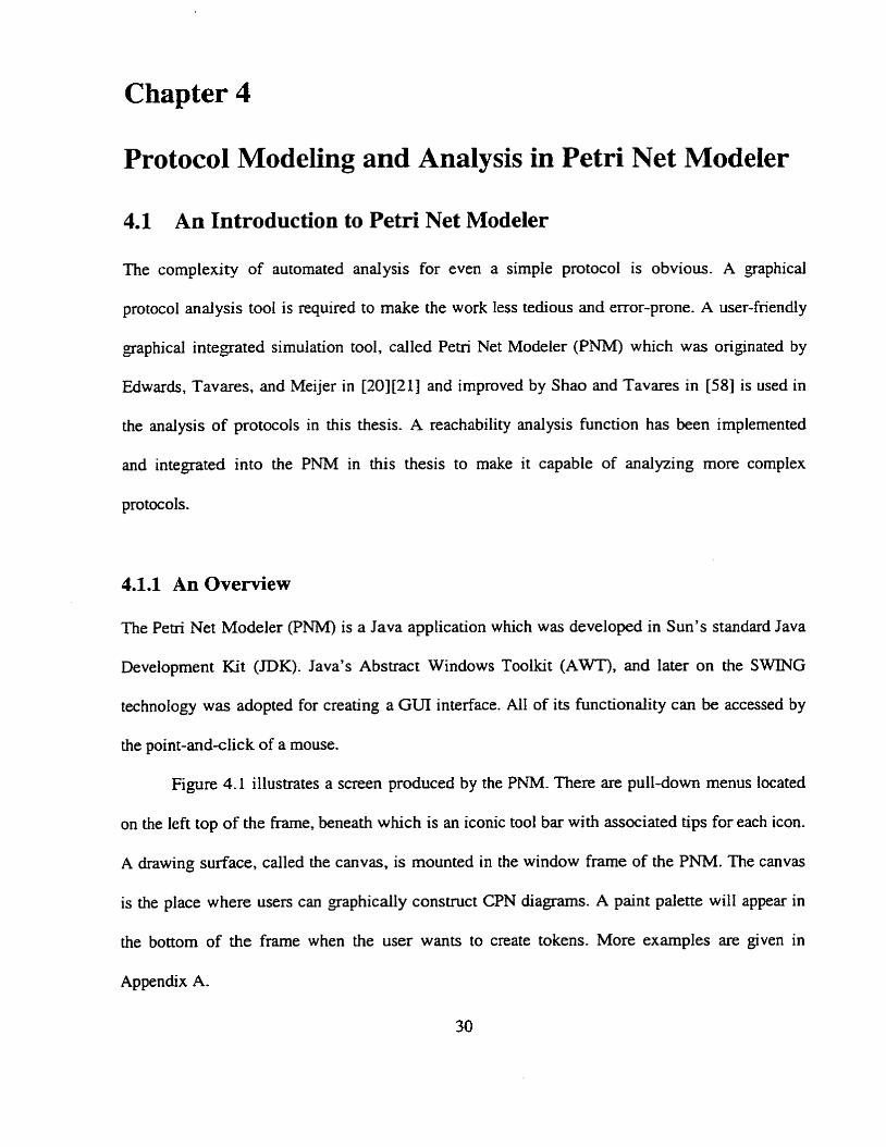
Figure 4.1 illustrates a screen produced by the P M . There are pull-down menus located
on the left top of the frarne, beneath which is an iconic tool bar with associated tips for each icon.
A drawing surface, called the canvas, is mounted in the window frarne of the PNM. The canvas
is the place where users cm graphicaily construct CPN diagrams. A paint palette will appear in
the bottorn of the frame when the user wants to create tokens. More examples are given in
Appendix A-
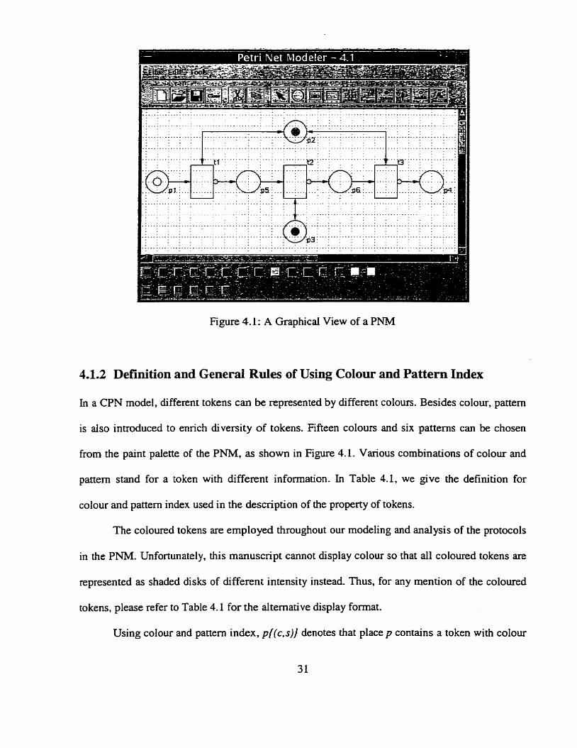
Figure 4.1 : A Graphical View of a PNM
1.1.2 Definition and General Rules of Using Colour and Pattern Index
In a CPN model, different tokens can be represented by different colours. Besides colour, pattern
is aiso introduced to enrich diversity of tokens. Fifteen colours and six patterns can be chosen
from the paint palette of the PNM, as shown in Figure 4.1. Various combinations of colour and
pattern stand for a token with different information. In Table 4.1, we give the definition for
colour and pattem index used in the description of the property of tokens.
The coloured tokens are employed throughout our modeling and analysis of the protocols
in the PNM. Unfortunately, this manuscript cannot display colour so that al1 coloured tokens are
represented as shaded disks of different intensity instead Thus, for any mention of the coloured
tokens, please refer to Table 4.1 for the alternative display format.
Using colour and pattern index, p{(c,s)] denotes that place p contains a token with colour
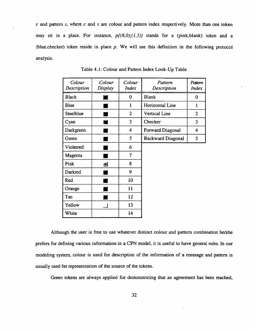
c and pattern s, where c and s are colour and panern index respectively. More than one token
rnay sit in a place. For instance, p{(8,0);(1,3)) stands for a (pink,blank) token and a
(blue,checker) token reside in place p. We will use this definition in the following protocoi
anal pis.
Table 4.1: Colour and Pattern Index Look-Up Table
Colour Colour Colour . Description 1 Display 1 Index 1
1 Black I m b l
1 Green I i 1 5 1
Blue
SteeIblue
1 Violetred 1 1 6
a a
Red . 10
1.
2
Magenta
Pink
Yellow
White 14
Pattern Descnption
rn BI
P m 1 Index 1
7
8
Horizontal Line 1 1 1 Vertical Line 1 2 1
Checker 1 3 1
Backward Diagonal 1 5 1
Although the user is free to use whatever distinct colour and pattern combination helshe
prefen for defining various information in a CPN model, it is useful to have general niles. In our
modeling system, colour is used for description of the information of a message and pattern is
usually used for representation of the source of the tokens.
Green tokens are always applied for demonstrating that an agreement has been reached,

for instance completing the authentication, while hlack ones indicate authentication failure.
Green tokens are also used for positive control information. e-g., a certain transition is ready to
fire. Red tokens sometimes imply wming information.
The tokens with a checker pattem are reserved for information related to an intruder; the
tokens with a horizontal lines or a vertical lines pattern are used by Iegitimate entities; the tokens
with a blank pattem usually are aven to information not dedicated to only one entity, such as
shared keyng matenal; the tokens with forward or backward diagonal pattem c m be used to
denote information altered by the intruders-
4.1.3 Features of the PNM
The PNM has a number of features for efficient automated protocol analysis, which are
highlighted in the following. Some of them are new for this version of the PNM.
Graphically manipulating on CPN components, such as places, transitions, tokens. (directed)
arcs, inhibitor arcs, PNOs, ports, labels, and texts, etc. Manipulating includes such things as
- creating, deleting, copying, selecting, moving or resizing.
ImportinglExporting CPN diagrams fromfto ASCII text files. Mer finishing rnanipulating on
a CPN diagram in the P M , it can be saved into an ASCII text file which is readable by any
text editor. The alternative to modifying a CPN diagram graphically cm be done by making
changes to the text file directly. This feature is especially helpful for making subtie changes
in a complex CPN system. An existing CPN diagram c m be reconstnicted by the information
parsed in from a text file.
Saving PNOs in separate ASCII text files, which allows the PNOs designed for general
purpose can be reused in other CPN systems, just like classes c m be widely used by
applications in an object-oriented prograrn Ianguage.
Opening multiple CPN diagrarns, which permits the user to work on different PNOs or
different levels of the same CPN system simuItaneousIy.
Performing reachability analysis by using either exhaustive search or stubborn set search to
construct a reachability graph from a aven initial state. The terminal states in the reachability
gaph will be used to determine whether or not the protocol is flawed. This is a new feature.
Keeping a record of al1 unique interior states within a reachability graph. These states are
useful for locating where the flaws rnight be in the protoc01 anaiysis. This is a new feature.
Discovenng a transition finng sequence path from a certain state to another state. This
feature is always used to find a transition firing sequence path from an initial state to an
insecure terminal discovered in reachability analysis. Knowing this path is useful to identify
possible attacks that could be performed by an intmder.
PIease refer to f20][21][58] for more detailed implementation information of the P M . In
the following sections, a protocol is given as an example to demonstrate how to mode1 and
analyze protocols using the P M .
4.2 The OAKLEY Protocol - an Example
Key establishment is at the heart of data protection that relies on cryptography, and it is an
essential component of packet protection mechanisms. A scalable and secure key distribution
mechanism for the Intemet is a necessity. The goal of the OAKLEY [ 5 q key determination
protocol is to provide such a mechanism, coupled with adequate cryptographie strength. The key
can be used later to derive security associations for the RFC 2402 1301 and RFC 2406 (311
protocols (AH and ESP) or to achieve other network security goals.
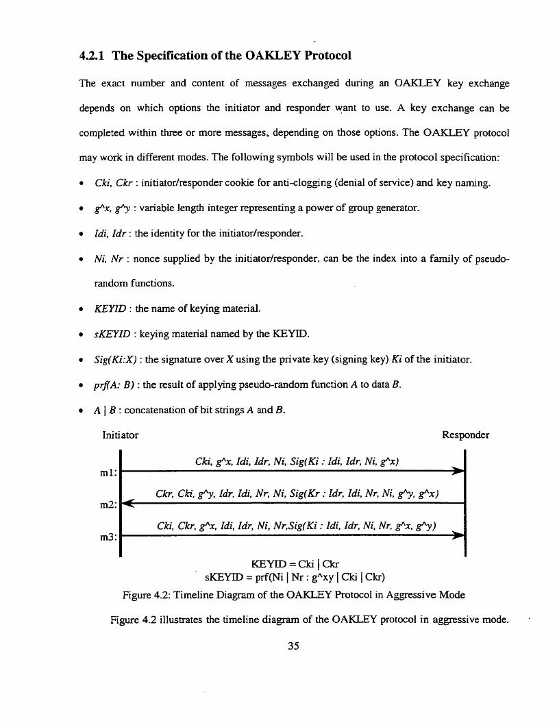
4.2.1 The Specification of the OAKLEY Protocol
The exact number and content of messages exchanged during an OAKLEY key exchange
depends on which options the initiator and responder want to use. A key exchange can be
completed within three or more messages, depending on those options. The OAKLEY protocol
may work in different modes. The following symbols wilI be used in the protocol specification:
Cki, Ckr : initiatorhsponder cookie for anti-clogging (denial of service) and key naming.
<.r, g"y : variable length integer representing a power of group generator.
Idi, Idr : the identity for the initiatorhesponder.
Ni, N r : nonce supplied by the initiatodresponder, c m be the index into a farnily of pseudo-
random functions.
KEYID : the name of keying material.
sKEYZD : keying material named by the KEYID.
Sig(Ki:X) : the signature over X using the private key (signing key) Ki of the initiator.
pf lA: B) : the result of applying pseudo-random function A to data B.
A 1 B : concatenation of bit strings A and B.
Ini ti ator Responder
ml:
KEYID = Cki 1 Ckr SKEYID = prf(Ni 1 Nr : gAxy 1 Cki 1 Ckr)
Cki, g"x, Zdi, Zdr, Ni, SiglKi : Idi, Zdr, Ni, e x ) '
m2:
m3:
Figure 4.2: Timeline Diagram of the OAKLEY Protocol in Aggressive Mode
Figure 4.2 illustrates the timeline diagram of the 0-Y protocol in aggressive mode. .
35
Ckr, Cki, g"y, Idr, Idi, Nr, Ni, Sig(Kr : Idr, Idi, Nr, Ni, ghy, e x ) < Cki, Ckr, e x , Idi, Idr, Ni, Nr,Sig(Ki : Idi, Idr, Ni, Nr, f x , f y )
'
Operating under this mode, the initiator generates a unique cookie Cki, a pseudo-randomly
selected exponent x, e x , nonce Ni, as well as two identities Zdi, Idr, one for the initiator one for
the responder respectively, and sends them together with signature to the responder.
In aggressive mode, the responder accepts al1 the information offered by the initiator.
When he receives the message fiom the initiator, he validates the signature over the signed
portion of the message. pnerates a unique cookie Ckr, nonce Nr, computes f y , forms the reply
message. and then signs the ID and nonce information with his private key and sends it to the
ini tiator.
The initiator receives the reply message and validates the signature, sen& the reply
message, signed with his public key. When the responder receives the initiator message, and if
the signature is valid, both sides mutually authenticate each other and share the same keying
material, which is cdcuiated as pMNi 1 Nr: Yxy 1 Cki 1 Ckr).
4.2.2 Modeling of the OAKLEY Protocol and Intruder Mode1 in the PNM
We adopt hierarchical modeling technology to model the protoc01 specification in two levels:
entity level and functional level, using the Petri Net Modeler (PNM). The hierarchical modeling
has the benefit of providing service without exposure of detail implementation information.
From entity level, we can have a whole picture of the protocol specification. Entities involved in
the protocol and message flows among entities are determined at this level. Detail
implementation information 1s given out at functionai level, where d l components: places.
transitions, and ports are labeled.
Other than legitirnate entities, we also introduce intruders who attempt to impersonate
legitimate entities by sitting in the communication channel between legitimate entities to
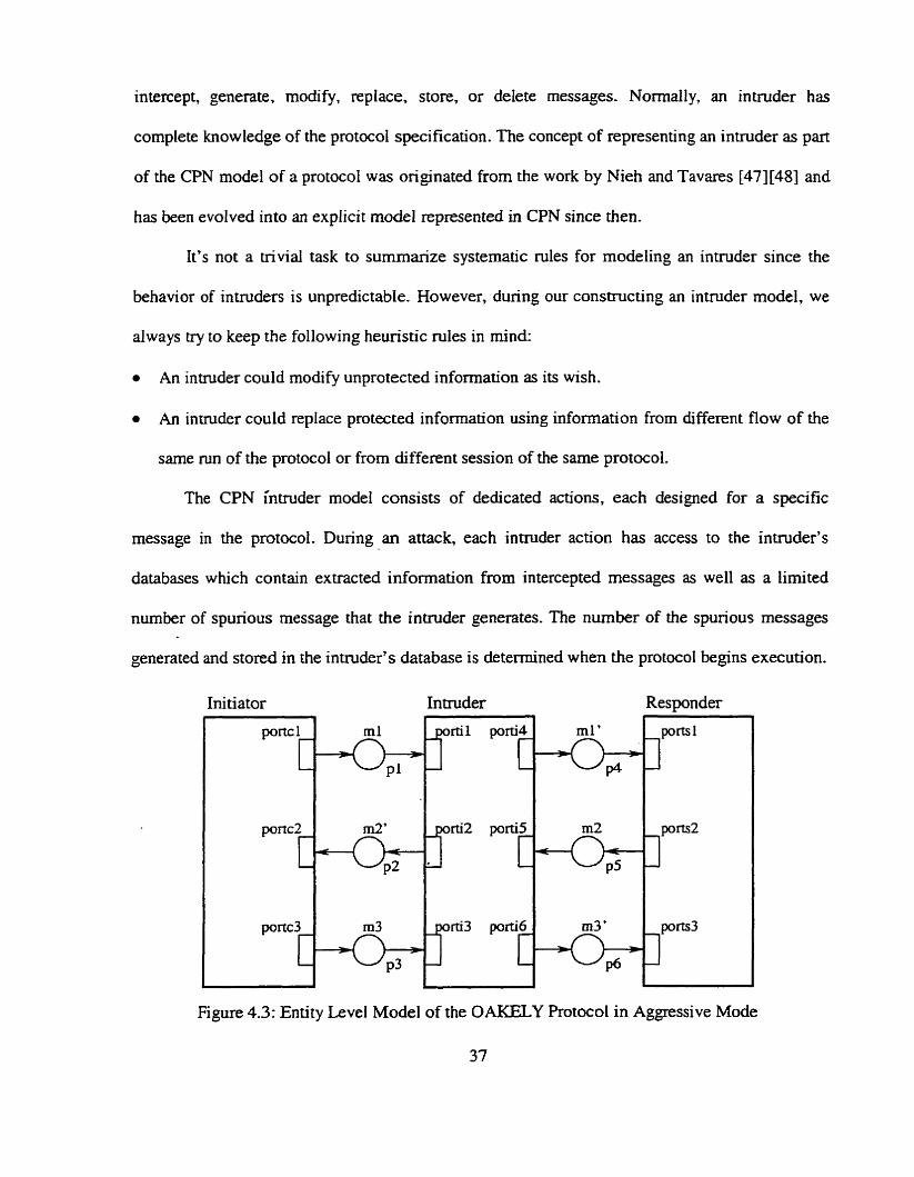
intercept, generate, modify, replace, store, or delete messages. Nomally, an intnider has
complete knowledge of the protocol specification. The concept of representing an intruder as part
of the CPN model of a protocol was originated from the work by Nieh and Tavares [47][48] and
has k e n evolved into an explicit mode1 represented in CPN since then.
It's not a trivial task to summarize systernatic niles for modeling an intruder since the
behavior of intruders is unpredictable. However, during Our constructing an intruder rnodel, we
always try to keep the following heuristic mies in mind:
An intnider couid modify unprotected information as its wish.
An intruder could replace protected information using information from different flow of the
same mn of the protocol or from different session of the same protocol.
The CPN intruder mode1 consists of dedicated actions, each designed for a specific
message in the protocol. During an attack, each intruder action has access to the intruder's
databases which contain extracted information from intercepted messages as well as a lirnited
nurnber of spurious message that the intruder generates. The nurnber of the spurious messages
generated and stored in the intruder's database is determined when the protocol begins execution.
h i tiator Intruder Responder
Figure 4.3: Entity Level Mode1 of the OAKELY Protocol in Aggressive Mode
37
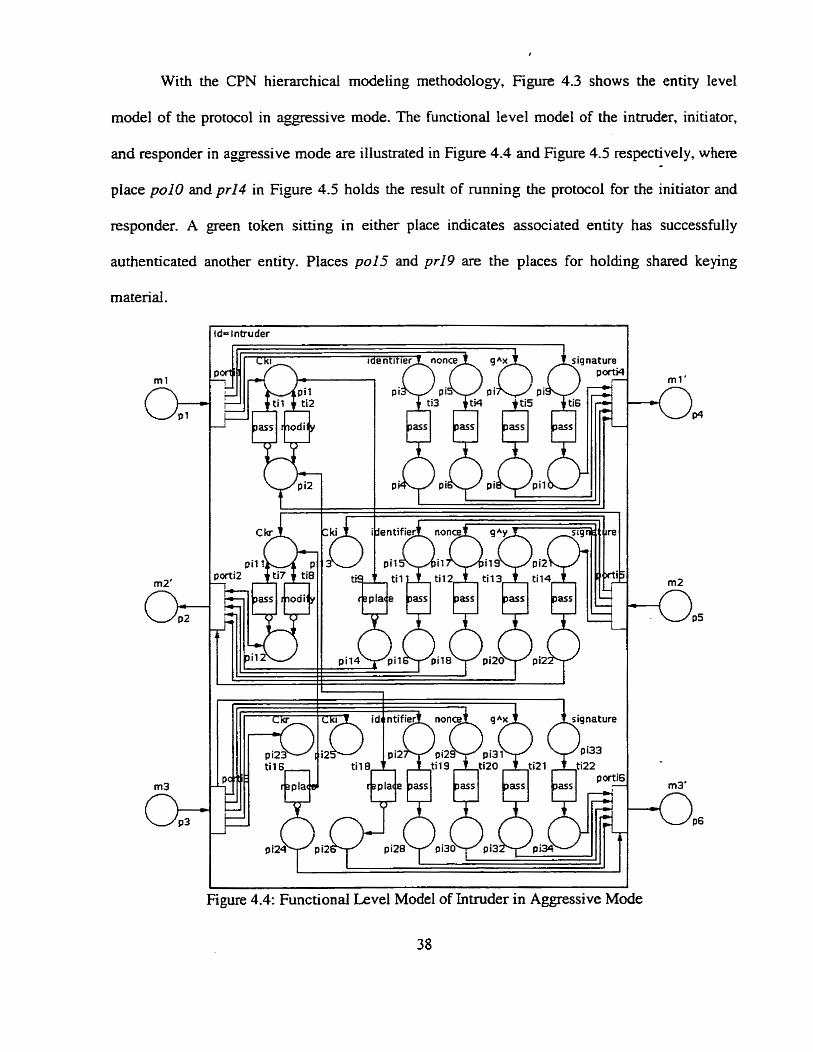
r
With the CPN hieranihical modeling methodology, Figure 4.3 shows the entity level
mode1 of the protocol in a g p s s i v e mode. The functional level mode1 of the intruder, initiator,
and responder in agpss ive mode are illustrated in Figure 4.4 and Figure 4.5 respectively, where
place polo and pr14 in Figure 4.5 holds the result of running the protocol for the initiator and
responder. A green token sitting in either place indicates associated entity has successfully
authenticated another entity. Places pu15 and pr19 are the places for holding shared keying
materiai.
= i ntruder
Figure 4.4: Functional Level Mode1 of Intnider in Aggressive Mode
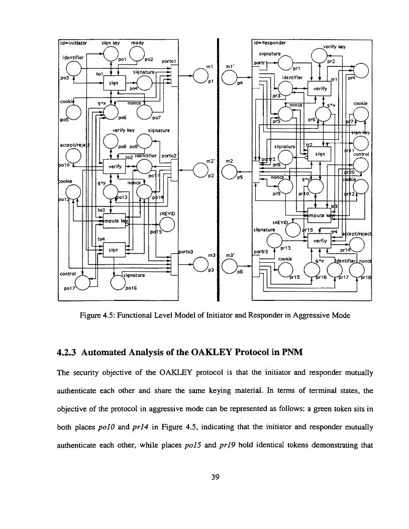
d-initiator sign key ready 17 n
d- Resoonder d e r i f y key
cookie i"'
Figure 4.5: Functional Level Mode1 of Initiator and Responder in Aggressive Mode
4.2.3 Automated Analysis of the OAKLEY Protocol in PNM
The security objective of the OAKLEY protocol is that the initiator and responder mutudly
authenticate each othzr and share the same keying material. In tesms of terminal States, the
objective of the protocol in aggressive mode c m be represented as follows: a green token sits in
both places polo and pr14 in Figure 4.5, indicating that the initiator and responder mutudly
authenticate each other, while places pol5 and pr19 hold identical tokens demonstrating that

both parties share the same keying materiai-
An initial state is .an arrangement of token distributions in the places at the point when the
protocol begins to execute. Different tokens sitting in the inïtiator's places and responder's
places indicates those places hold different information. Figure 4.6 is an initial state for the
initiator and responder. The intruder does not know any information More the protoc01
executes.
Table 4.2 tabdates the exhaustive reachability search results of the execution of the
protocol from the initial state shown in Figure 4.6 ,on Sun Ultra 1 workstation. The security
properties of the protocol can be determineci by examining the analysis results.
Table 4.2: Reachability Analysis Results for the OAKLEY Protocol in Agpssive Mode
1 l 1 # unique interior states 1 2539 (
# terminai states with a green token sitting in pol O and pr14 and the same token sitting in po15 and prl9 14
The first row of the table represents the number of unique interior states, which are found
during the exhaustive reachability search. This value is directly related to the time consumed
in the search.
The second row of the table gives the total number of distinct terminal states ùiat cm be
reached during the protocol execution. A terminal state is a state with no enabled transitions.
According to the reachability property of the CPN, more than one terminal state may be
reached from a given initial state. Whether the security objectives of the protocol are
subverted cm ?x determined by exarnining these terminal states.
40
4
5
# temiinal states with a green token sitting in polo and pr14 and different token siüing in pu15 and pr19
Running time (sec) 20 1.43
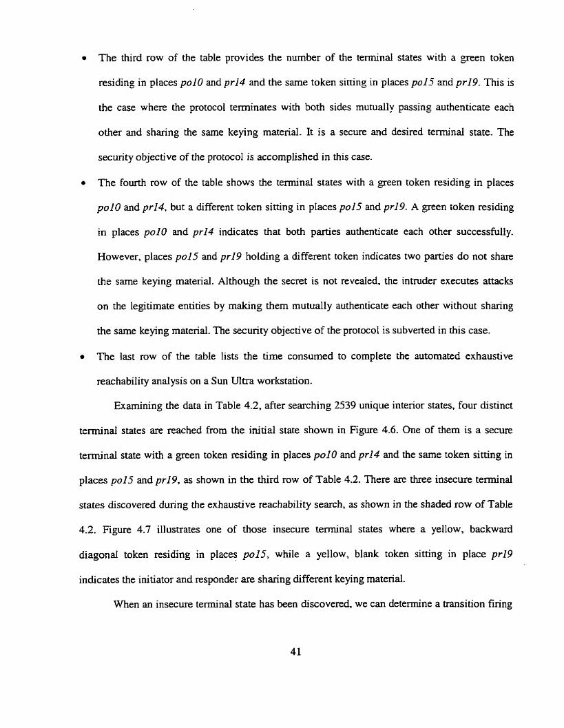
The third row of the table provides the number of the terminal states with a green token
residing in places polo and prI4 and the sarne token sitting in places po15 and pr19. This is
the case where the protocol terminates with both sides mutually passing authenticate each
other and sharing the sarne keying material. It is a secure and desired terminai state. The
security objective of the protocol is accomplished in this case.
The fourth row of the table shows the terminal states with a green token residing in places
polo and pr14, but a different token sitting in places 9015 and pr19. A green token residing
in places polo and pr14 indicates that both parties authenticate each other successfully.
However, places po15 and pr19 holding a different token indicates two parties do not share
the same keying material. Although the secret is not revealed, the intruder executes attacks
on the legitimate entities by making them mutually authenticate each other without sharing
the same keying material. The security objective of the protocol is subverted in this case.
The last row of the table lists the time consumed to complete the automated exhaustive
reachability andysis on a Sun UItra workstation.
Examining the data in Table 4.2, afier searching 2539 unique interior states, four distinct
terminal states are reached from the initial state shown in Figure 4.6. One of them is a secure
terniinal state with a green token residing in places poIO and pr14 and the same token sitting in
places pu15 and pr19, as shown in the third row of Table 4.2. There are three insecure terminal
states discovered during the exhaustive reachability search, as shown in the shaded row of Table
4.2. Figure 4.7 illustrates one of those insecure terminal states where a yellow, backward
diagonal token residing in places pol5, while a yellow, blank token sitting in place pr19
indicates the initiator and responder are sharing different keying material.
When an insecure terminal state has been discovered, we can determine a transition firing
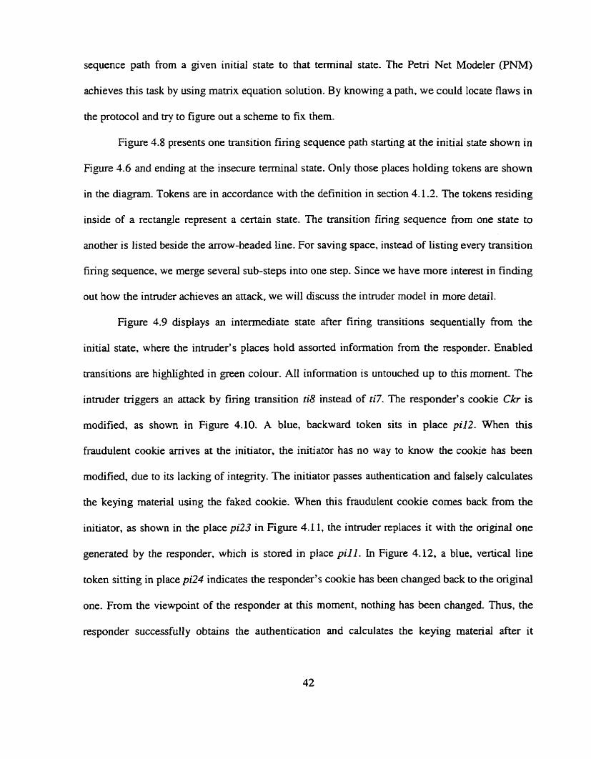
sequence path from a given initiai state to that terminai state. The Petri Net Modeler (PNM)
achieves this task by using matrix equation solution. By knowing a path, we could locate flaws in
the protocol and try to figure out a scheme to fix them.
Figure 4.8 presents one transition firing sequence path starting at the initial state sbown in
Figure 4.6 and ending at the insecure temiinal state. Only those places holding tokens are shown
in the diagram. Tokens are in accordance with the definition in section 4.12. The tokens residing
inside of a rectangle represent a certain state. The transition firing sequence from one state to
another is listed beside the arrow-headed line. For saving space, instead of listing every transition
firing sequence, we merge several sub-steps into one step. Since we have more interest in finding
out how the intruder achieves an attack, we will discuss the intruder mode1 in more detail.
Figure 4.9 dispiays an intermediate state after firing transitions sequentially from the
initial state, where the intnider's places hold assorted information from the responder. Enabled
transitions are highlighted in green colour. Al1 information is untouched up to this moment The
intmder triggers an aîtack by firing transition ti8 instead of ti7. The responder's cookie Ckr is
modified, as shown in Figure 4.10. A blue, backward token sits in place p i l 2 . When this
fraudulent cookie arrives at the initiator, the initiator has no way to know the ctiokie has been
modified, due to its lacking of integrity. The initiator passes authentication and falsely calculates
the keying materiai using the faked cookie. When this fraudulent cookie cornes back from the
initiator, as shown in the place pi23 in Figure 4.1 1, the intnider replaces it with the original one
generated by the responder, which is stored in place p i l l . In Figure 4.12, a blue, vertical line
token sitting in place pi24 indicates the responder's cookie has k e n changed back to the original
one. From the viewpoint of the responder at this moment, nothing has been changed. Thus, the
responder successfully obtains the authentication and calculates the keying material after it
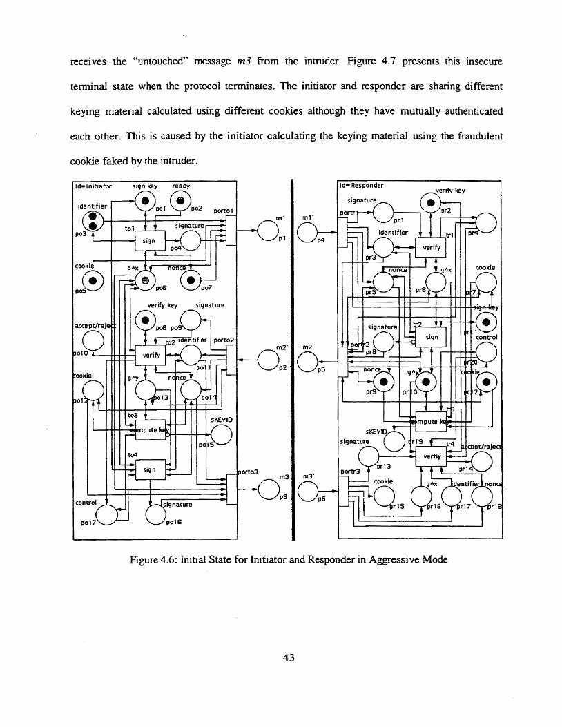
receives the "untouched" message m3 from the intruder. Figure 4.7 presents this insecure
temiinal state when the protocol terminates. The initiator and responder are sharing different
keying material calculated using different cookies although they have mutually authenticated
each other. This is caused by the initiator calculating the keying material using the fraudulent
cookie faked by the intruder.
1 id- initiator siqn key raady 1
I
Figure 4.6: Initial State for
d- Responder d e r i f y key
Initiator and Responder in Aggressi Mode
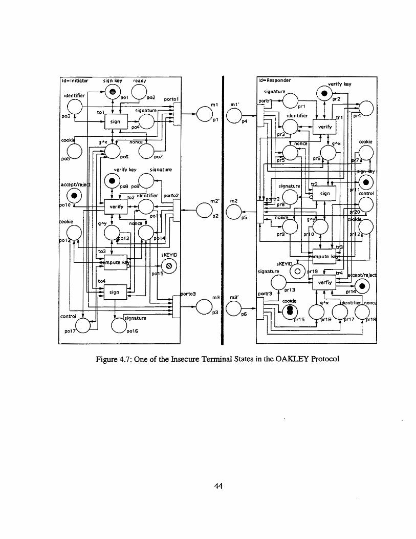
dslnitiator sign k y ready n n
d- Responder ~ e r i Q ke y
Figure 4.7: One of the Insecure Terminal States in the OAKLEY Rotocol
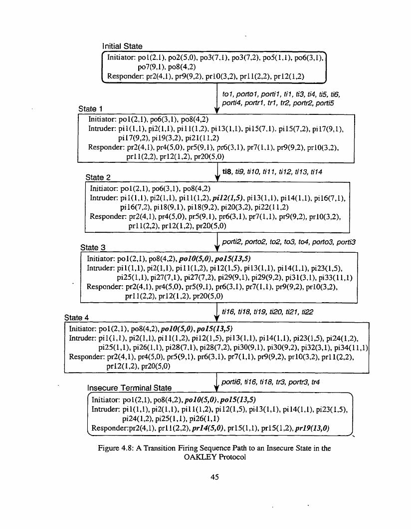
to 1, porto 1, porti 7, til , ti3, ti4, ti5, ti6, porti4, portr 1, trl , tr2, portR, porfi5
State 1 Initiator: po 1(2,1), po6(3, l), po8(4,2) Inmider: pil(l,l), pi2(1,1), pi 1 1(1,2), pi 13(l,l), pi15(7,1), pi15(7,2), pi 17(9,1),
pi17(9,2), pi 19(3,2), piZl(11,S) Responder: prW,If , pr4(5,0), pr5(9,1), pr6(3,1), pr7(L, l), pr9(9,2), ~rlO(3.2)~
prl1(2,2), pr12(1,2), pr20(5,0)
ti8, ti9, t i lO, fil 1 , t1'12, ti13, t if4 State 2 I 1
Initiator: po1(2,1), po6(3,1), po8(4,2) h - u d e ~ pi I ( l , lh @(l,l), pi 1 1(1T2)T pi12(&5), pi13(171), pi14(1,1), pil6(7,1),
pi16(7,2), pi18(9,1), pi18(9,2), pi20(3,2), pi22(11,2) Responder: pr2(4.1), pr4(5,0), pr5(9, l), 1). pr7(l, l), pr9(9,2). pr10(3,2),
~ r l l ( 2 . 2 ) ~ p r W 1,2), pr20(S70)
porti'2, port02, t02, t d , porf03, po/ti3 State 3
1
til6, ti18, ti19, ti20, ti21, ti22 State 4
1
Initiator: po1(2,1), po8(4,2), po10(5,0), po15(13,5) h t d e r : pi 1(171), pi2(171-), pi 1 1(1,2), pi12(1,5), pi13(1,1)7 pi l4(l,l), pi23(1,5), piX(1 .2),
pi25(1,1), pi26( LI), pi28(7,1). pi28(7,2), pi30(9,1), p130(9,2), piX(3, 1), pi34(11,1) Responder: prW, l), pr4(5,0), p d W ) , pr6(3,1), pr7( LI), pr9(9,2), pr10(3,2), Pr1 1(2,2),
pr12( 1,2), pr20(5,0)
porti6, ü16, ti18, tr3, portr3, tr4 lnsecure Terminal State R
Initiator: po l(2, l), po8(4,2), po10(5,O), po15(13,5) htmkr: p i l ( l , h pi2(17 l), pi1 1(172), pi l2(1,5), pi43(l7l), pil4(1,1), pi23(1,5),
pi24(1,2), pi25(1,1). pi26(1, 1) Responder:pr2(4,1). ~ r l l ( 2 . 2 ) ~ prI4(5,0), pr15(1, l), pr15(1,2), pr19(13,0) l
Figure 4.8: A Transition Firing Sequence Path to an Insecure State in the OAKLEY Protocol
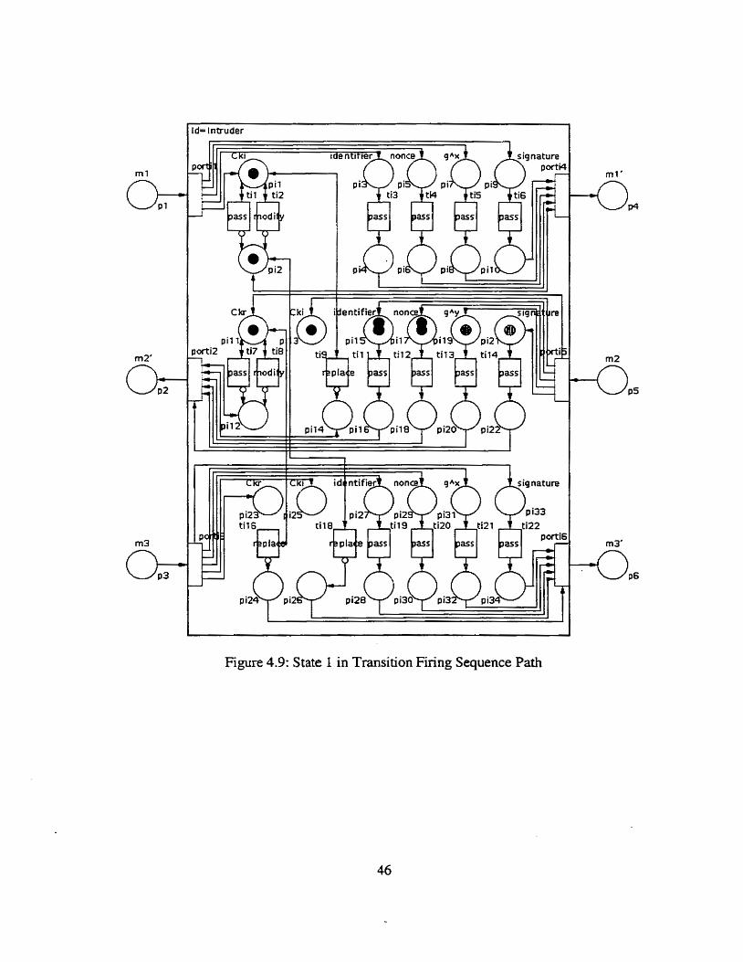
= Intruder
Figure 4.9: State 1 in Transition Firing Sequence Path
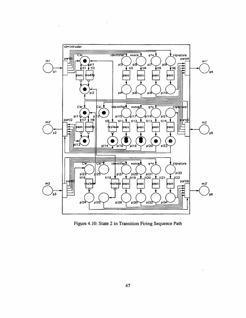
- Intruder
Figure 4.10: State 2 in Transition Firing Sequence Path
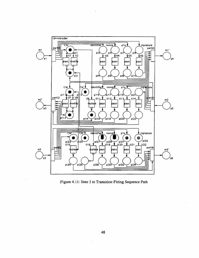
Figure 4.11 : State 3 in Transition Firing Sequence Path
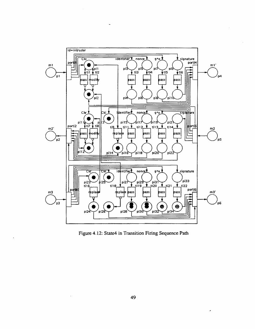
I I l l
Figure 4.12: State4 in Transition Firing Sequence Patb
4.2.4 Modification of the OAKLEY Protocol
The purpose of the automated analysis is to determine protocol Aaws quickly and easily. But ihis
is not the final goal of this thesis. In addition to discovering protocol flaws, we aiso propose
schemes to fix them. PNO based protocol models are well designed for this purpose. The old
PNO rnodel can be easily replaced with a modified one. The protocol with a new PNO mode! is
run again until no flaw exists any more. The intruder's PNO mode1 is not mûdified since we
cannot stop an intruder from doing something. However, we can modify legitimate entities' PNO
models to fix the flaws found in the protocol.
Using automated analysis tool, a fIaw is discovered in the OAKLEY protocol by
examining the data in the fourth row of Table 4.2. Three insecure terminal states can be reached
from a specific initial state shown in Figure 4.6. In these insecure terminal states, the initiator
and responder rnutually authenticate each other without sharing the same keying material. Figure
4.7 illustrates one of the insecure terminal states. As discussed in the previous section, it happens
when the initiator calculates the shared keying material using the responder's cookie Ckr, which
has been altered by the intmder in message m2. This flaw is caused by the lack of integrity of the
cookies.
Having determined the flaw in detail, we now try to fix it by modifjmg the initiator
andor responder's PNO rnodel. Figure 4.13 shows the timeline d i a m of the modified
OGKLEY protocol in aggressive mode. Since the onginal protocol lacks essential integrity of the
cookies, we provide this mechanism by signing cookies in al1 three messages.
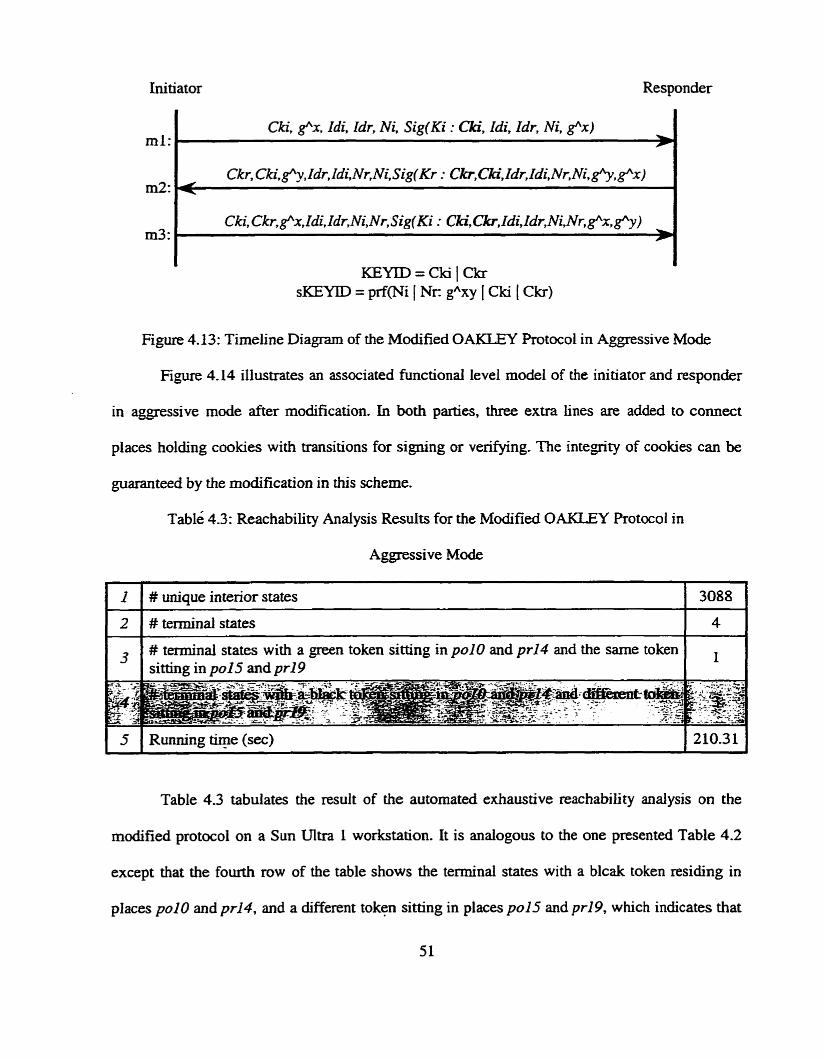
Initiator Responder
ml:
m2:
rn3:
Cki, e x , Zdi, Idr, Ni. Sig(Ki : Ckï, Idi, Idr, Ni, f x ) -
KEYID=CkiICkr sKEMD = prf(Ni ( Nr: gAxy [ Cki 1 C h )
Figure 4.13: Timeline Diagram of the Modified OAKLEY Protocol in Aggressive Mode
Figure 4.14 illustrates an associated functional level mode1 of the initiator and responder
in aggressive mode after modification. In both parties, three extra lines are added to connect
places holding cookies with transitions for signing or verQing. The integrity of cookies can be
guaranteed by the modification in this scheme.
able 4.3: Reachability Analysis Resuits for the Modified OAKLEY Protocol in
Aggressive Mode
( 5 1 Running tiqe (sec) 1 210.31 1
I
2
3
Table 4.3 tabulates the resuit of the automated exhaustive reachability analysis on the
modifiecl protocol on a Sun Ultra 1 workstation. It is analogous to the one presented Table 4.2
except that the fourth row of the table shows the terminal states with a blcak token residing in
places polo and pr14, and a different token sitting in places po15 and pr19, which indicates that
# unique interior States
# terminal states
# teminal states with a green token sitting in pu10 and pr14 and the same token sitting in pu15 and pr19
3088
4
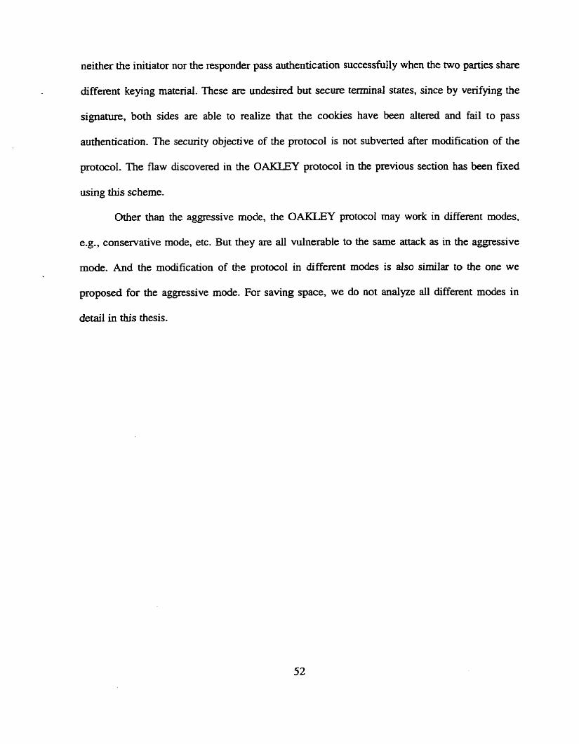
neither the initiator nor the responder pass authentication successfully when the two parties share
different keying material. These are undesired but secure terminal States, since by verifying ihe
signature, both sides are able to realize that the cookies have b e n altered and fail to pass
authentication. The security objective of the protocol is not subverted after modification of the
p t o c o l . The flaw discovered in the OAKLEY protocol in the previous seaion has been fixed
using this scheme.
Other than the aggressive mode, the OAKLEY protocol may work in different modes,
e.g., conservative mode, etc. But they are ail wlnerabie to the same attack as in the aggressive
mode. And the modification of the protocol in different modes is also
proposed for the aggressive mode. For saving space, we do not analyre
detail in this thesis.
similar to the one we
al1 different modes in
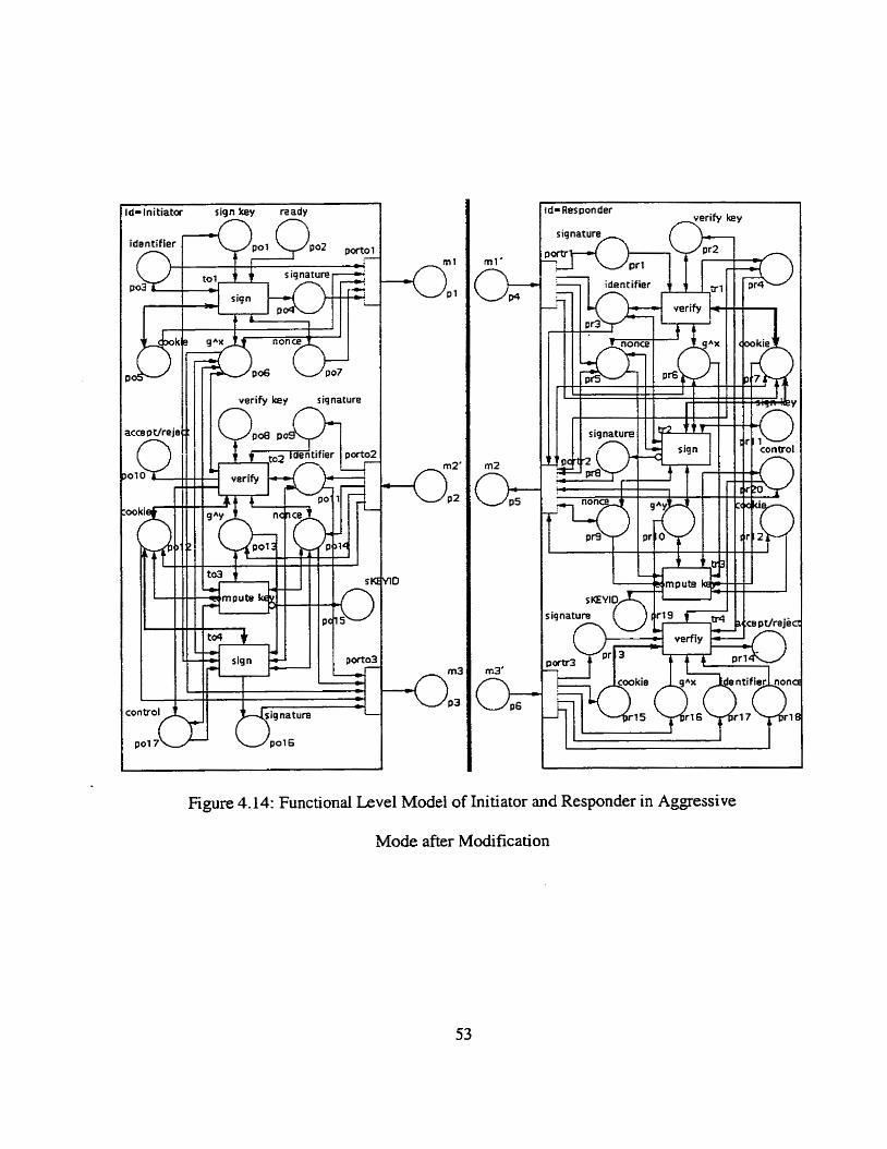
i-initiatac siqn by nady /-? n
- Respon der
signature,,
Figure 4.14: Functional Level Model of Initiator and Responder in Aggressive
Mode after Modification

Chapter 5
Automated Security Analysis of ONC RPC Protocol
The ONC (Open Nenvork Computing) RPC (Remote Procedure Call) protocol [12] provides the
fields necessary for a client to identify itself to a server, and vice versa. in each cal1 and reply
message. Secwity and access control mechanisms can be built on top of this message
authentication. The Diffie-Hellman authentication rnechanism and some other mechanisms cm
be supported.
n e ONC RPC protocol consists of two phases. Phase 1 involves exchanging a certified
public key between a client and server to arrive at a long-term cornrnon key. Phase 2 deals with a
client distributhg its short-term conversation (session) key, which is used to authenticate itself to
a server and vice versa.
5.1 The Specification of the ONC RPC Protocol
The timeline diagram of Phase 1 of the ONC RPC protocol is illustrated in Figure 5.1, where:
Cel-r: certificate used by the client and server.
Kc : comrnon key. A DES key that is derived from the Diffie-Hellman public and pnvate
keys.
KS : conversation (session) key. It is a DES key, which the client generates and passes to the
server in the first RPC cal1 of a session.
ts : timestarnp.
ts-l : timestamp venfier.
tr : lifetime of conversation key.
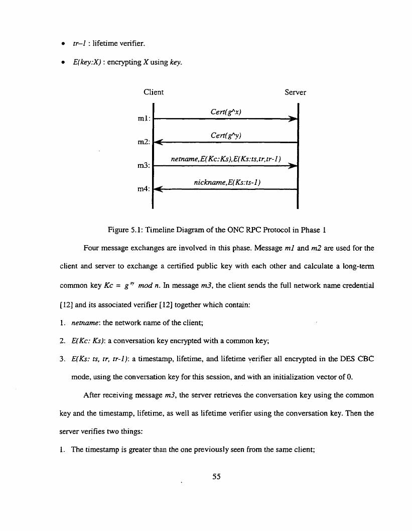
tr-I : lifetime verifier.
E(key:X) : encsrpting X using key.
Client
ml:
m3:
m3:
m4:
Figure 5.1: Timeiine Diagram of the ONC RPC Protocol in Phase 1
Four message exchanges are invoived in this phase. Message ml and m2 are used for the
client and server to exchange a certified public key with each other and calculate a long-term
common key Kc = g q mod n. In message m3, the client sen& the full network name credentiai
[12] and its associated verifier [12] together which contain:
1. nemarne: the network narne of the client;
2. E( Kc: Ks): a conversation key encrypted with a common key;
3. E(Ks: rs, tr, tr-1): a timestamp, lifetime, and lifetime verifier al1 encrypted in the DES CBC
mode, using the conversation key for this session, and with an initialization vector of O.
After receiving message m3, the server retrieves the conversation key using the common
key and the timestamp, lifetime, as well as lifetime verifier using the conversation key. Then the
server verifies two things:
1. The timestamp is greater than the one previously seen from the same client;
.-
2. The timestamp has not expired by checking that the server's time is earlier than the sum of
the client's timestamp plus lifetime.
Also. as an added check, the server checks that the lifetime verifier is equal to the Iifetime
minus 1. If al1 checks succeed, the server accepts the credential.
In message m4, the server sen& back nickname and, encrypted timestamp verifier E(Ks:
1s-1). which should be timestamp minus 1. The client is dso required to check the verifier
returned frorn the server to be sure that it is legitirnate. At the termination of the protocol, the
client and server are munially authenticated and share the same comrnon key as well as
conversation key. The client must mn Phase 1 in its first transaction with the server to amive at a
long-term cornmon key.
Phase 2 is analogous to the second part of Phase 1 (m3 and m4), except that a client haç a
choice of using nickname instead of nemame. Phase 2 runs in each cal1 and reply message.
Figure 5.2 shows the timeline diagram for Phase 2-of the ONC RPC protocol.
Client Server
Figure 5.2: Timeline Diagram of the ONC RPC Protocol in Phase 2
ml:
5.2 Modeling of the ONC RPC Protocol
nickname, E(Kc:Ks), E(Ks:ts, tr, tr- 1 )
5.2.1 Modeling of Phase 1
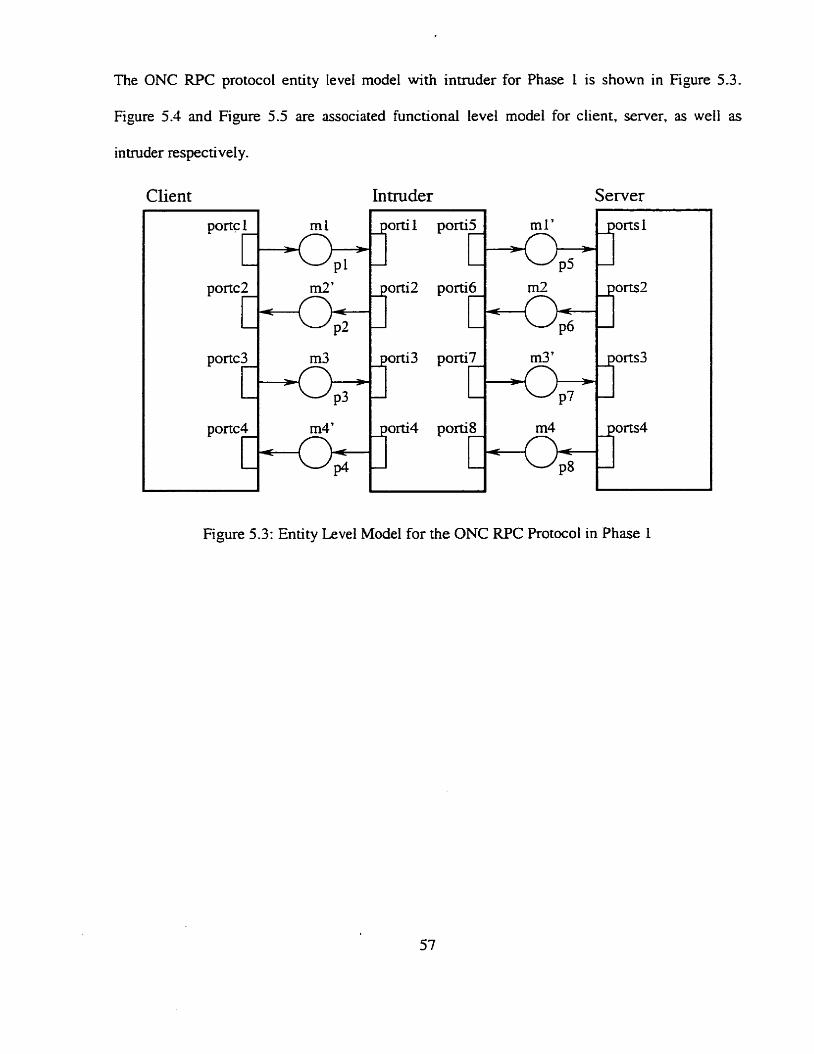
The ONC RPC protocol entity level model with intruder for Phase 1 is shown in Figure 5.3.
Figure 5.4 and Figure 5.5 are associated functïonal level model for client, server, as weil as
intruder respective1 y.
Client In tmder Server
Figure 5.3: Entity Level Mode1 for the ONC RPC Rotocol in Phase 1
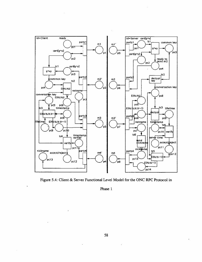
n icknarne
conversation key
b3 lifetime
Figure 5.4: Client & Server Functional Level Mode1 for the ONC W C Protocol in
Phase 1
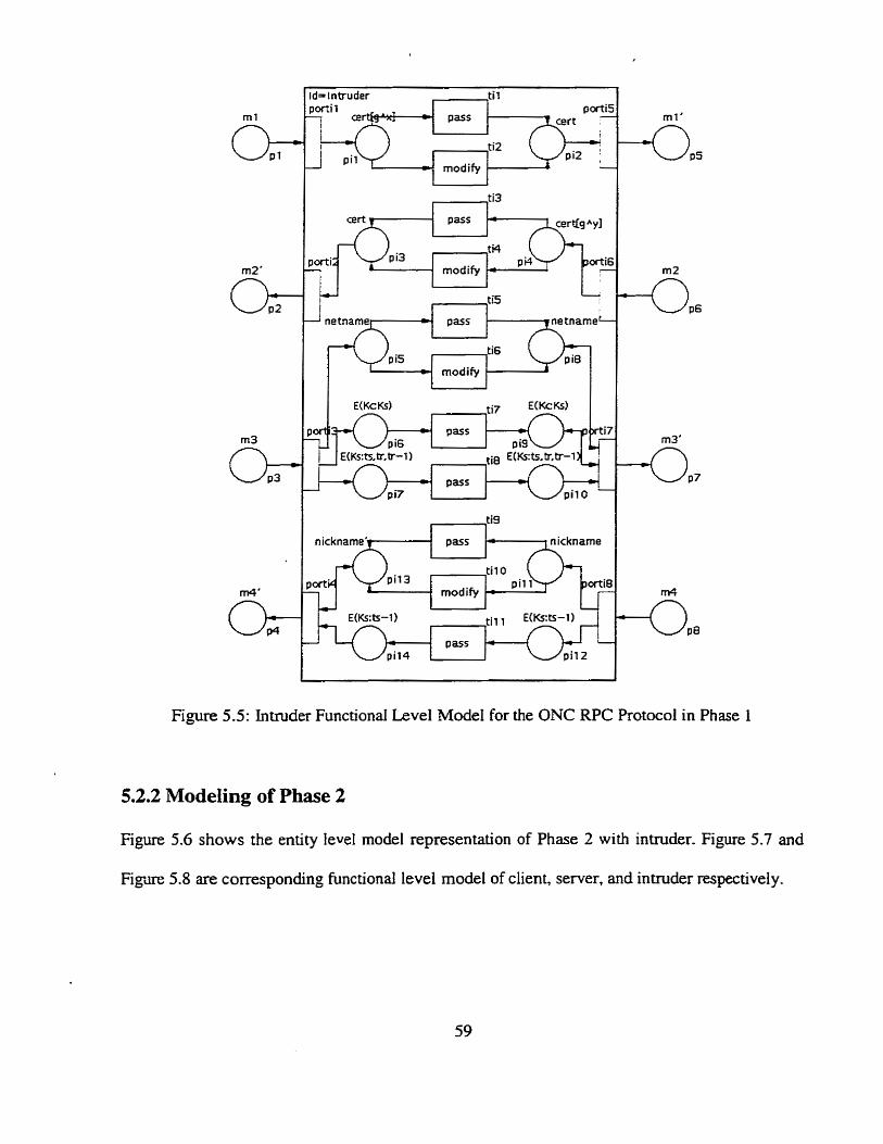
j= intruder , Ji1
modify
modify
m l '
Figure 5.5: Inmider Functional Level Mode1 for the ONC RPC Protocol in Phase 1
5.2.2 Modeling of Phase 2
Figure 5.6 shows the entity level model representation of Phase 2 with intruder. Figure 5.7 and
Figure 5.8 are corresponding hnctional level model of client, semer, and intmder respectively.
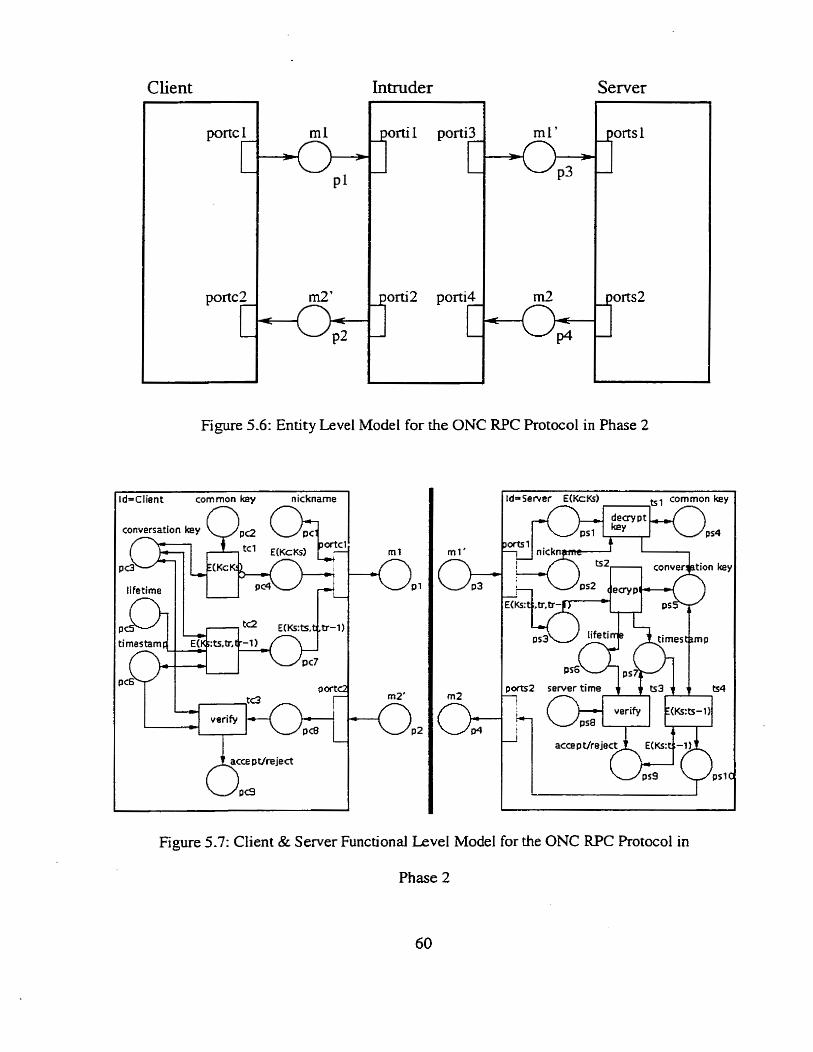
Client I
I
Figure 5.6: Entity Level Model for the ONC RPC Protocol in Phase 2
d-Client commonkay nickname
verify r 1-2 server time j ts3 j ts4
verify E(Ks:tr-1)
PSI C
Figure 5 -7: Client & Server Functional LeveI Model for the ONC RPC Protocol in
Phase 2
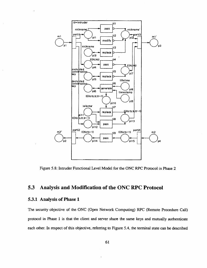
nicknarne
replace
Figure 5.8: Intnider Functional Level Mode1 for the ONC RPC Protocol in Phase 2
5.3 Analysis and Modification of the ONC RPC Protocol
5.3.1 Analysis of Phase 1
The security objective of the ONC (Open Network Computing) WC (Remote Procedure Call)
protocol in Phase 1 is that the client and server share the same keys and mutually authenticaie
each other. In respect of this objective, referring to Figure 5.4, the terminal state can be described

as follows:
pc4 = ps3 & pc5 = ps8 & pc7 = ps7 & pc12 = ps12 = green
Running the simulation tool in the PNM, the analysis results of the exhaustive
reachability search from an initial state shown in Figure 5.9 are tabulated in Table 5.1. Whether
the security objectives of the protocol are subverted c m be determined by examining the analysis
results.
Table 5.1: Anaiysis Results for the ONC RPC Protocol in Phase 1
1 1 1 # unique interior States 1686 I
1 6 ( Running time (sec) 1 48.07 1
4
The first row in the table shows the nurnber of distinct states reached dunng the execution of
the protocol.
The second row in the table gives the number of unique terminai states reached after the
execution of the protocol.
The third row in the table represents the number of teminal states with a green token sining
in plac& pc12 and p l 2 and indicates that the two parties successfully authenticated each
other. Identical tokens sitting in places pc4 and ps3, pc5 and ps8, pc7 and ps7 indicate that
the client and server share the same common key, conversation key, and the server is aware
of the identity of the client. This is a secure and desirable terminal state. It îs the case where
the protocol accomplishes its secuity objectives.
The fourth row in the table shows the number of temiinal states with a black token sining in
#{pc4 # ps3 andhr pc5 # pst? & pc12 = ps12 = black) 9
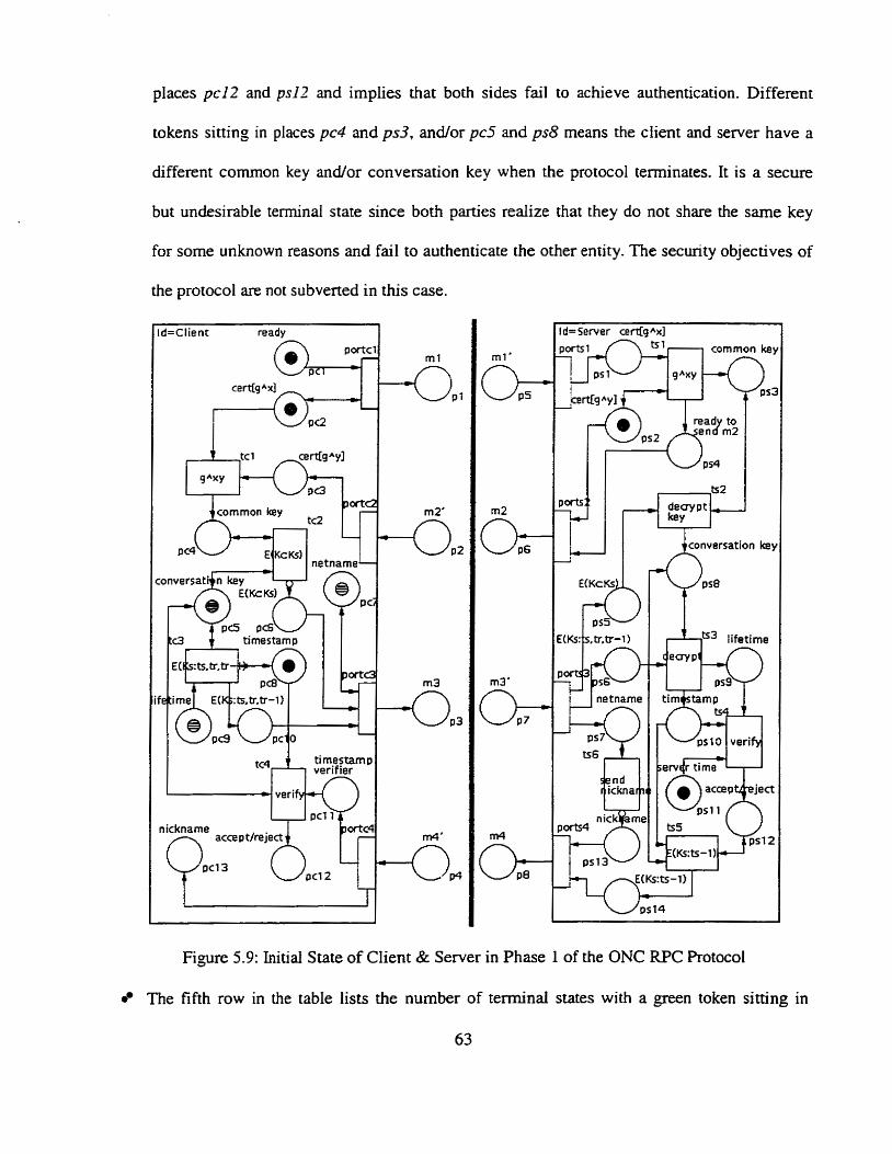
places pcl2 and ps17 and implies that both sides fail ro achieve authentication. Different
tokens sitting in places pc4 and ps3, andor pc5 and ps8 means the client and server have a
different cornmon key ancilor conversation key when the protocol terminates. It i s a secure
but undesirable terminal state since both parties reaiize that they do not share the same key
for some unknown reasons and fail ro authenticate the other entity. The security objectives of
the protocol are not subvened in this case.
d=~lient ready
n
ti rnestamp verif ier
veri
nickname
Q c c e ~ t / r e j e I j pc12 q= ~4
5 send r icknar?c r
ts5 C
E(Ks:ts-1) -c.
psl 1 0 -=ka
Figure 5.9: Initial State of Client & Server in Phase 1 of the ONC RPC Protocol
The fifth row in the table lists the nurnber of temiinal States with a green token sitting in
63
places pc12 and p l 2 and indicates that the client and server mutually authenticate each
other. Different tokens sitting in places pc7 and ps7 means chat the server does not know the
real identification of the client. This is an insecure and undesirable terminal state. In this
case, the seclirity objectives of the protocol are subverted,
The last row in the table is the running time of the protocol analysis on a Sun Ultra
workstation.
By exarnining the analysis results in Table 5.1, one insecure terminal state has been
discovered, as shown by the shaded row in the table. Figure 5.10 illustrates this insecure terminal
state, where the inmider successfully changes the netname (refer to place ps7 in the server),
which is sent by the client to venfy its identity. A yellow token with a checker pattern indicates
the intruder has modified the information. The original token representing nemame should be
yellow with a horizontal line pattern, as shown in place pc7. This modification causes the server
to falsely think that it is cornmunicating with a client. other than the one who sends its
identification. Neither is the client aware that its netname has been changed. since the subsequent
nicknarne sent back from the server is just an unsigned integer standing for the client's
identification. In Figure 5.10, places pc12 and ps12 both hold a green token, which indicates that
the client and server successfully authenticate each other. Therefore, in Phase 1, it is possible that
both sides mutually authenticate each other without knowing exactly with whom they are
dealing, although the intruder does not have knowledge of the common key and conversation
key. So, Phase L is vulnerable to unknown key-share anack against the server.
Knowing the insecure terminal state and its corresponding initiai state, we c m use the
mavix equation solution method to determine a transition firing sequence path between them.
Knowing this path is helpfui for locating attacks performed by the intruder. Figure 5.1 1 is one of
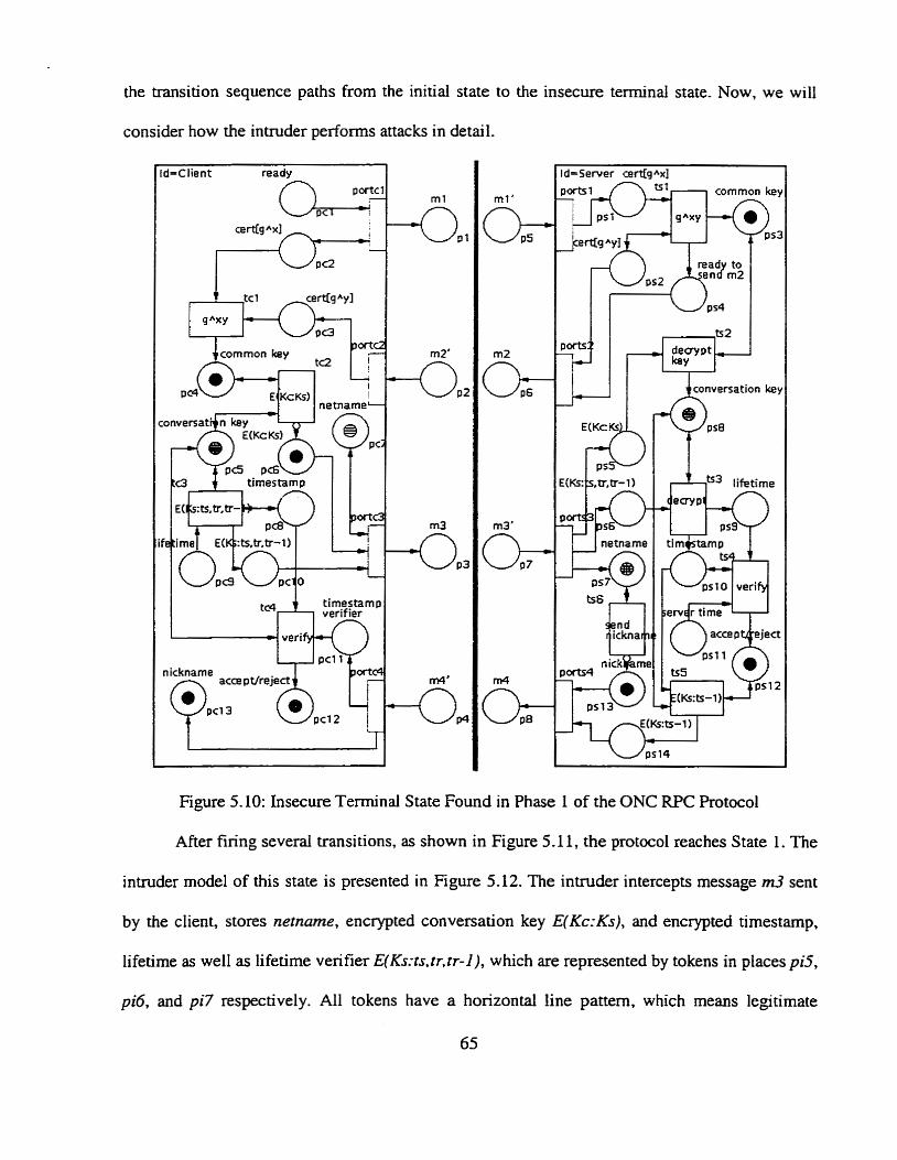
the transition sequence paths from the initial state to the insecure terminal state. Now, we will
consider how the intmder perfoms attacks in detail.
u 2 netname
tirnestamp verifier
veri
nickname
pc12
! l netname
pslO veri rn erv d r tinte
Figure 5. IO: Insecure Terminal State Found in Phase 1 of the ONC RPC Protocol
After firing several transitions. as shown in Figure 5.11, the protocol reaches State 1. The
intmder mode1 of this state is presented in Figure 5.12. The intruder intercepts message m3 sent
by the client, stores netnnme, encrypted conversation key E( Kc:Ks), and encrypted timestamp,
lifetime as well as lifetime verifier E(Ks:ts.tr.tr-1), which are represented by tokens in places pi5,
pi6, and pi7 respectively. Al1 tokens have a horizontal line pattern, which means legitimate
65
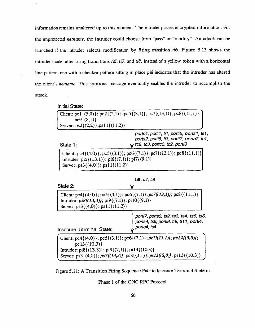
information remains undtered up to this moment. The intruder passes encrypted information. For
the unprotected netname, the inuuder could choose from "pass" or "rnociify". An attack can be
iaunched if the intruder selects modification by firing transition ti6. Figure 5.13 shows the
invuder mode1 afier firing transitions ti6, ri7, and riB. Instead of a yellow token with a horizontal
line pattern, one with a checker pattern sittïng in place pi8 indicates that the intruder has altered
the client's nemame. This spurious message evenrually enables the intruder to accomplish the
attac k.
l nitial State:
c l i en t : pc1{(5,0)}; pc2{(2,1)}; pc5{(3,1)}; pc7{(13,1)}; pf8((11,1));\ pc9 { (891) )
Server: ps2 { (2,2) } ;ps 1 1 { (1 1.2) 1 J
portc 1, porti 1 , til , porti5, ports 1, ts 1, ports2, porti6, ti3, porti2, port&, tc 1,
State 1 : 4 tc2, tc3, portc3, tc2, porti3
Client: pc4{(4,0)}; pc5((3,1)}; pc6{(7,1) 1; pc7{(13,1)}; pc8{ (1 1.1)) Intruder: pi5{(13,1)}; pi6{(7,1)}; pi7{(9,1)} Server: ps3{(4,0)}; ps11{(11,2)}
State 2:
Ciienr: pc4{(4,0) 1; pc5{(3,1)1; pc6((7,1)};pc7{(13,1)]; pc8((1 LI)} Intmder: pi8{(13,3)]; pi9 {(7,l) 1 ; pi 10{ (9,1)} Server: ps3{(4,0) ); ps11{(1 I,2) }
Insecure Terminal State: J. portC4, tc4
Figure 5.1 1 : A Transition Firing Sequence Path to Insecure Terminal State in
Phase 1 of the ONC W C Protocol
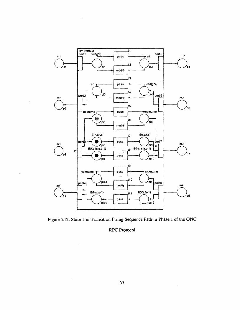
nickname'
parti4 1
Figure 5.12: State 1 in Transition Firing Sequence Path in Phase 1 of the ONC
RPC Protocol
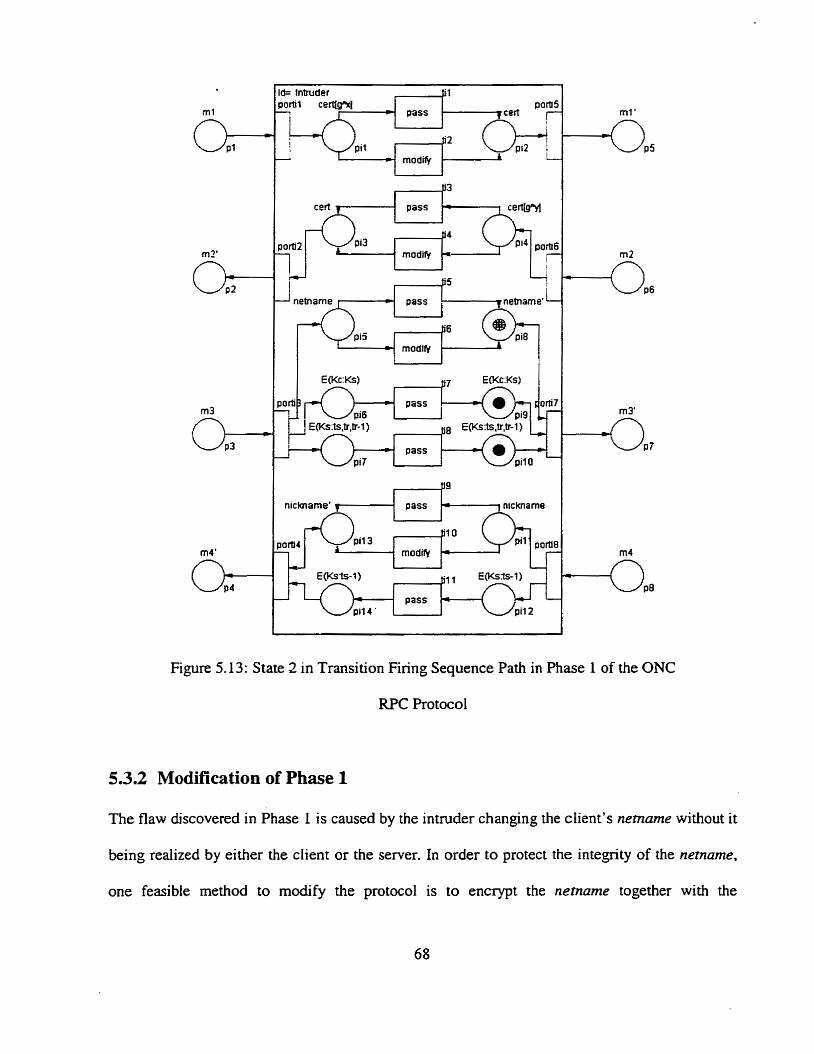
ch- P
pass
.- A
np-l pass lr6 pi3
mod*
Figure 5.13: State 2 in Transition Finng Sequence Path in Phase 1 of the ONC
RPC Protocol
5.3.2 Modification of Phase 1
The flaw discovered in Phase 1 is caused by the intnider changing the client's nemame without it
being realized by either the client or the semer. In order to protect the integrity of the nemame,
one feasible method to modify the protocol is to encrypt the nemurne together with the
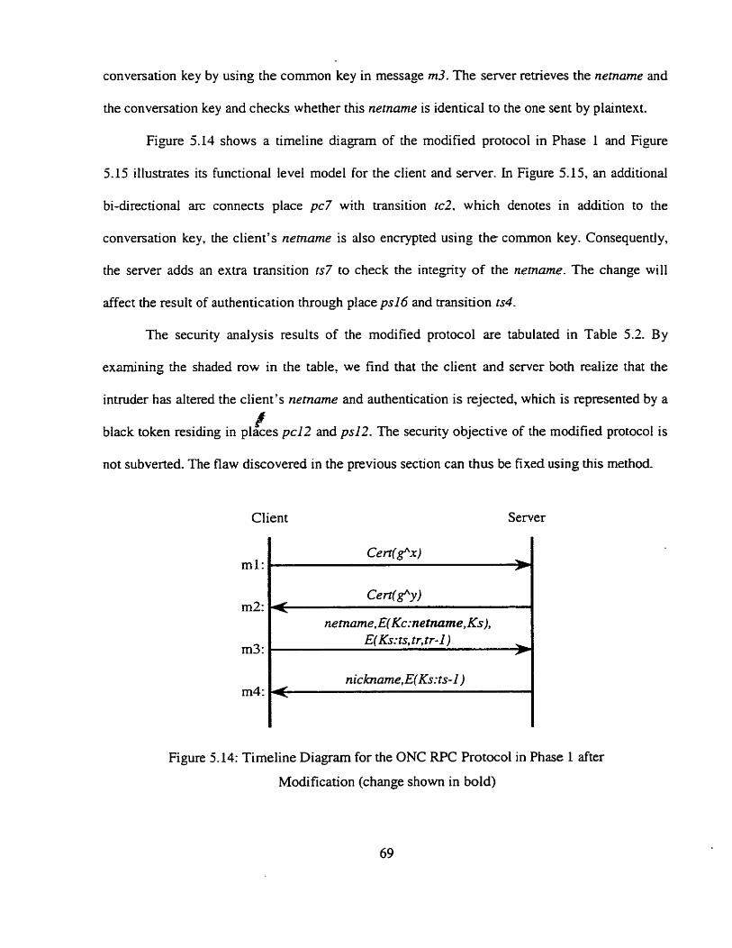
conversation key by using the comrnon key in message m3. The server retrieves the netnarne and
the conversation key and checks whether this netnarne is identical to the one sent by plaintext.
Figure 5.14 shows a timeline diagram of the modified protocol in Phase 1 and Figure
5.15 illustrates its functional level mode1 for the client and server. In Figure 5.15, an additional
bi-directionai arc connects place pc7 with transition tc2, which denotes in addition to the
conversation key, the client's nemame is also encrypted using the common key. Consequently,
the server adds an extra transition ts7 to check the integrity of the netname. The change will
affect the resuit of authentication through place ps16 and transition ts4.
The security analysis results of the modified protocol are tabulated in Table 5.2. By
examining the shaded row in the table, we find that the client and server both realize that the
intruder has altered the client's netname and authentication is rejected, which is represented by a
a black token residing in places pc12 and ps12. The security objective of the modified protocol is
not subverted. The flaw discovered in the previous section c m thus be fixed using this method.
Client Server
ml: Cen(g'N
I netname. E( Kc:netnante, Ks),
Figure 5.14: Timeline Diagram for the ONC RPC Protocol in Phase 1 after
Modification (change shown in bold)
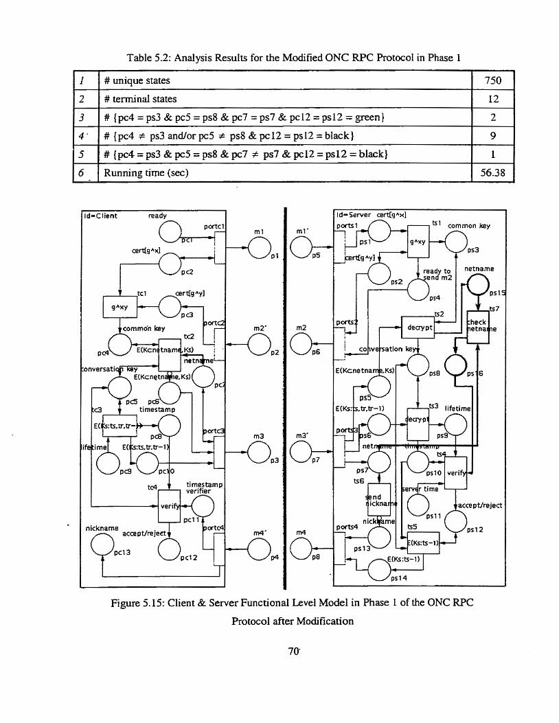
Table 5.2: Analysis Results for the Modified ONC W C Protocol in Phase I
2 1 # terminal states I l2
# unique States 750
d=Client ready 1 d- Server certfs Axl
3
9
1
56.38
3
4 .
5
send r icknar
nick m u-4 -i
#(pc4=ps3&pc5=ps8&pc7=ps7&pc12=ps12=green}
# { p c 4 # ps3andorpc5 t ps8&pc12=ps12=black}
# {pc4 = ps3 & pc5 = ps8 & pc7 # ps7 & pc12 = ps12 = black}
Figure 5.15: Client & Server Functional Level Mode1 in Phase 1 of the ONC RPC
Protocol after Modification
6 Running time (sec)
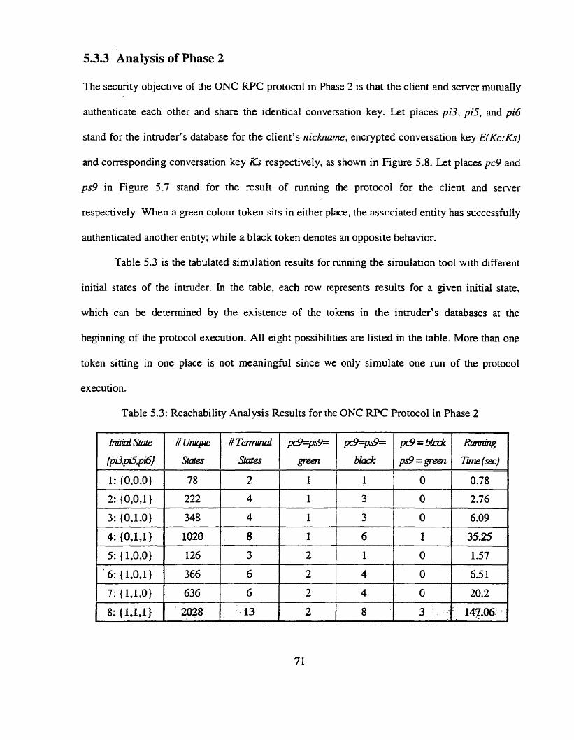
53.3 Analysis of Phase 2
The security objective of the ONC RPC protocol in Phase 2 is that the client and server mutually
authenticate each other and share the identical conversation key. Let places pi3, pi5, and pi6
stand for the intmder's database for the client's nicharne, encrypted conversation key E(Kc:Ks)
and corresponding conversation key Ks respectively. as shown in Figure 5.8. Let places pc9 and
ps9 in Figure 5.7 stand for the result of running the protocol for the client and server
respectively. When a geen colour token sits in either place, the associated entity has successfully
authenticated another entity; w hile a black token denotes an opposite behavior.
Table 5.3 is the tabulated simulation resuits for running the simulation tool with different
initial States of the inuuder. In the table, each row represents results for a given initial state,
which cm be detennined by the existence of the tokens in the inwuder's databases at the
beginning of the protocol execution. Al1 eight possibilities are Iisted in the table. More than one
token sitting in one place is not meaningful since we only simulate one m n of the protocol
execution.
Table 5.3: Reachability Analysis Results for the ONC RPC Protocol in Phase 2

There are three different types of terminal states listed in Table 5.3:
pc9 = ps9 = green
A green token sits in places pc9 and ps9, which means that both sides successfully
authenticate each other. This is secure and desirable terniinal state.
pc9 = ps9 = black
Places pc9 and ps9 contains a black token simultaneously, which indicares that both entities
fail to mutually authenticate for some unexpected reason. This is a secure but undesirable
terminal state, since both sides notice that attack has been performed by the intnider.
pc9 = black; ps9 = green
This terminal state is neither secure nor desirable, since the server approves authentication
while the client does not. This is the case where the intruder has executed an attack
successfully.
By examining Table 5.3, we find one and three insecure terminal states in case4 and
case8, respectively, which are shaded in the table. We anaiyze case4 in more detail to see how to
reach the insecure terminal state. Case8 has very sirnilar properties although there are three
insecure states.
The initial state of the client and the server for case4 is shown in Figure 5.17. The
intruder's initial state is shown in Figure 5.16. Tokens with a forward diagonal pattern sitting in
the intmder's databases pi5 and pi6 denote that the intnider knows a pair of old conversation key
and its corresponding encrypted form. Figure 5.18 shows the insecure terminal state of the client
and server discovered in case4, in which a black token sits in place pc9 while place ps9 holds a
green one.
The client sen& message ml to the server to start the protocol. In Figure 5.19, the
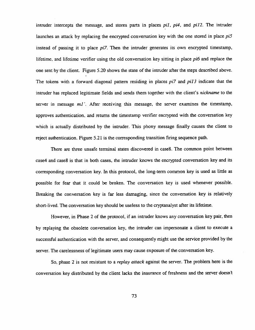
intruder intercepts the message, and stores parts in places p i l , pi4, and piI2. The intruder
launches an attack by replacing the encrypted conversation key with the one stored in place pi5
instead of paçsing it to place pi7. Then the intruder generates its own encrypted timestarnp,
lifetime, and lifetime verifier using the old conversation key sitting in place pi6 and replace the
one sent by the client. Figure 5.20 shows the state of the intruder after the steps descnbed above.
The tokens with a fonvard diagonal pattern residing in places pi7 and pi13 indicate that the
intruder has replaced legitirnate fields and sends them together with the client's n i c h m e to the
server in message ml '. M e r receiving this message, the server examines the timestamp,
approves authentication, and returns the timestamp verifier encrypted with the conversation key
which is actually distributed by the intruder. This phony message finally causes the client to
reject authentication. Figure 5.21 is the corresponding transition firing sequence path.
There are three unsafe terminal States discovered in case8. The common point between
case4 and case8 is that in both cases, the intruder knows the encrypted conversation key and its
corresponding conversation key. In this protocol, the long-term c o m o n key is used as little as
possible for fear that it could be broken. The conversation key is used whenever possible.
Breaking the conversation key is far less darnaging, since the conversation key is relatively
short-lived. The conversation key should be useless to the cryptanalyst &ter its lifetime.
However, in Phase 2 of the protocol, if an intruder knows any conversation key pair, then
by replaying the obsolete conversation key, the intruder can impersonate a client to execute a
successful authentication with the server, and consequently rnight use the service provided by the
server. The carelessness of legitimate users may cause exposure of the conversation key.
So, phase 2 is not resistant to a replay attack against the server. The problem here is the
conversation key distributed by the client lacks the insurance of freshness and the server doesnt
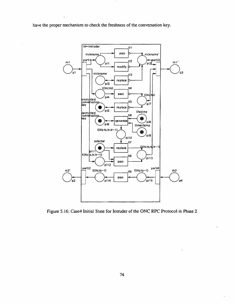
have the proper mechanism to check the freshness of the conversation key.
re place lifetime
generate p i8
Figure 5.16: Case4 Initial State for Intnider of the ONC RPC Protocol in Phase 2
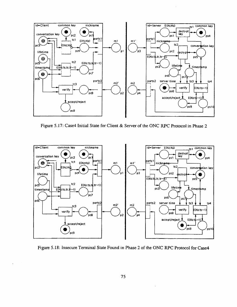
d=Client commonkey nickname Id=Server E!KcKs) tsl cornrnon key
m t '
semer time f 4 ts3 $ f t54
verify E(Ks:tS-1) verify b-
Figure 5.17: Case4 Initial State for Client & Server of the ONC RPC Protocol in Phase 2
1 id-Client common key nickname [
Figure 5.18: Insecure Terminai State Found in Phase 2 of the ONC W C Protocol for Case4
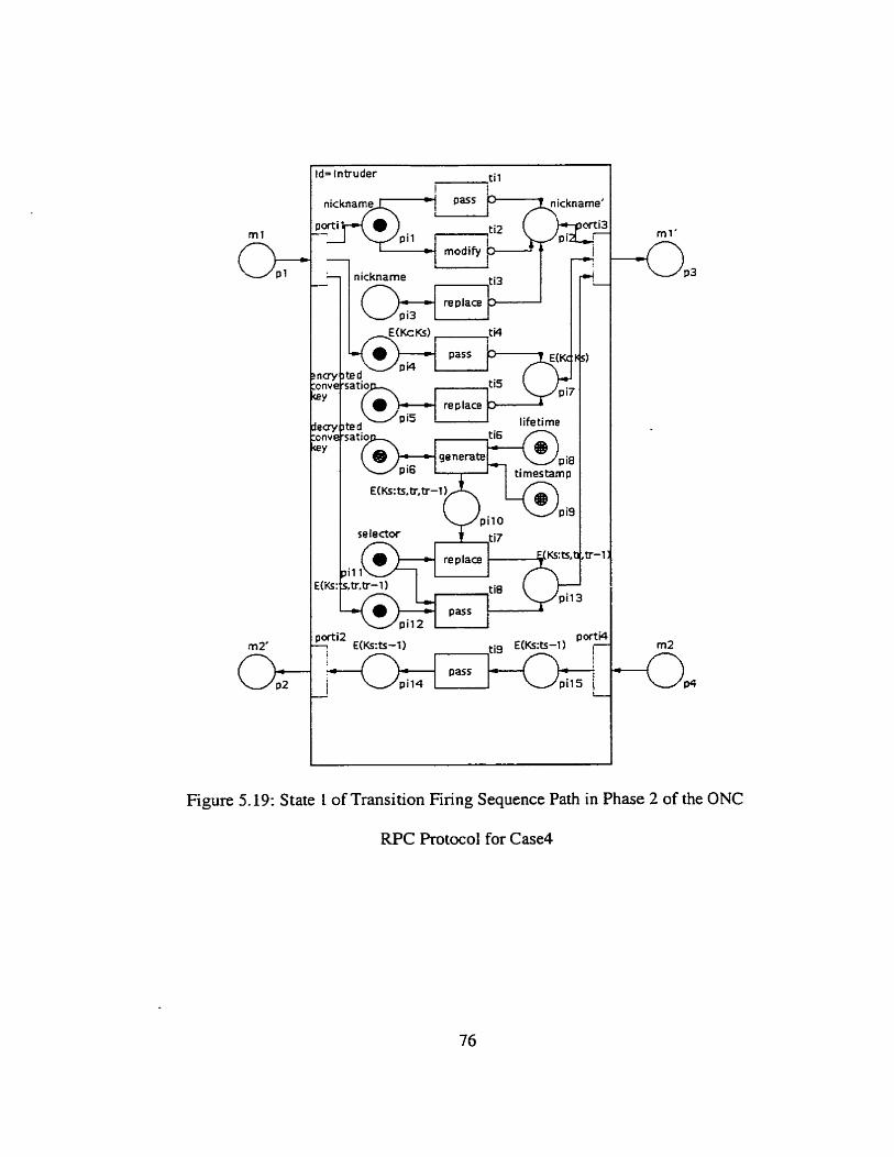
nickname
replace
P i5 lifetirne
selector
re place
pi1 2
Figure 5.19: State L of Transition Firing Sequence Path in Phase 2 of the ONC
RPC Protocol for Case4
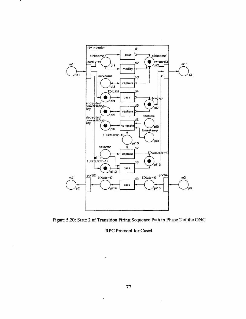
d= lntruder , {il
replace lifetime
generate timestam I
Figure 5.20: State 2 of Transition Firing Sequence Path in Phase 2 of the ONC
RPC Protocol for Case4
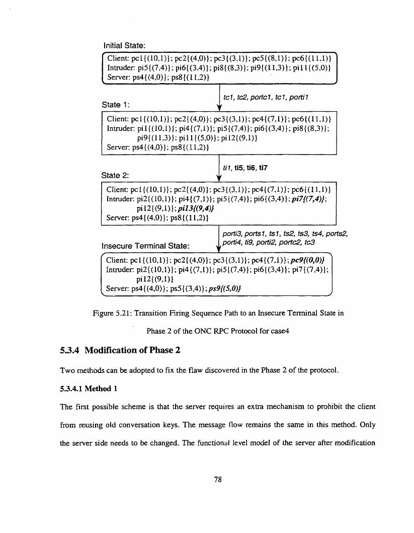
Initial State:
State 1:
Client: pc1((10,1)}; pc2{(4,0)}; pc3((3.1)}; pc4{(7,1)); pc6{( l lJ)} hmder: pi1 WOJ)}; pi4((7,1) 1; pi5{(7,4]}; pi6((3,4)}; pi8{(8,3)];
pig{(l l ,3)); pi1 1 {(5,O)); pi U{(g , l ) ) Server: ps4{(4,0)); ps8 ((1 l,2) )
State 2:
l nsecure Terminal State:
Figure 5.21: Transition Firing Sequence Path to an Insecure Terminal State in
Phase 2 of the ONC RPC Protocol for case4
5.3.4 Modification of Phase 2
Two methods can be adopted to fix the flaw discovered in the Phase 2 of the protocol.
5.3.4.1 Method 1
The first possible scheme is that the server requires an extra mechanism to prohibit the client
from reusing oid conversation keys. The message fiow rernains the same in this method. Only
the server side needs to be changeci- The functional level moael of the server after modification
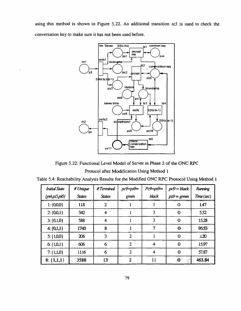
using this method is shown in Figure 5.22. An additional transition ts5 is used to check the
conversation key to rnake sure it has not been used before.
s e m r tirne 4 b 3 + + b4
Figure 5.22: Functional Level Mode1 of Server in Phase 2 of the ONC RPC
ProtocoI after Modification Using Method 1
Table 5.4: Reachability Analysis Results for the Modified ONC EUT Protocol Using Method 1

Table 5.4 presents analysis results after running the modified protocol using Method 1.
There are no more insecure terminal states under this attack.
. Unfortunately, this scheme is not scalable since the server needs enough memory space to
keep a record of al1 conversation keys used by each client and the time and storage consumed in
verifjnng old keys may increase greatly. Moreover, to keep the record secure is not a ûivial rask.
5.3.4.2 Method 2
Another possible modification is that the client encrypts the timestarnp together with the
conversation key using the cornmon key to ensure the freshness of the keys the client is going to
use for the coming session. By checking the timestamp bound with the conversation key, the
server can convince itself that the conversation key it just received is fresh. Figure 5.23 shows
the modified tirneline diagram of the protocol using this method. Figure 5.24 is the modified
client and server functional leveI mode1 using method 2. The client encrypts the tirnestarnp with
the conversation key indicated by adding an extra bi-directional line connecting place pc6 with
transition tcl . On the server side, transition ts5 is added to check the freshness of the
conversation key.
Client Server
ml:
m2:
Figure 5.23: Timeline Diagram of Modified the ONC RPC Protocoi in Phase 2
Using Method 2 (bold item indicates modifications)
Table 5.5 is analysis results for the modified protocol using Method 2. Insecure terminal
states no longer exist. The flawed protocol has been fixed-
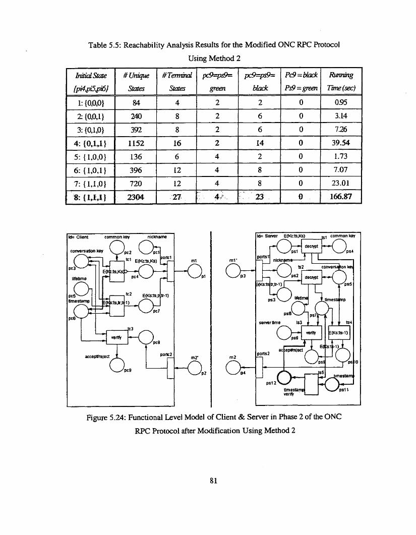
Table 5.5: Reachabiiity Analysis Results for the Modified ONC RPC Protocol
Using Method 2
tlmesiam psl 1
Figure 5.24: Functional Levei Mode1 of Client & Server in Phase 2 of the ONC
RPC Protocol after Modification Using Method 2
5.4 Conclusion We adopt one of the properries of Coloured Petri Nets, namely, reachabiliry, in ow analysis of
the security objectives of the ONC RPC protocol. The idea is to examine al1 reachable terminal
States to discover any flaw or weakness, which may enable an intnider to subvert security
objectives of a protocol. Using this scheme. one flaw has been discovered in each phase.
In Phase 1, an intruder is able to execute an unknown key-share attack against a server by
alterinp a client's nemame. Both parties approve authentication, but the server is not aware of the
real identification of the client. The client and server do not detect this attack because of the lack
of the integrity of netname. This flaw cm be fixed by adding imperative integrity accordingly.
The modified protocol is not vulnerable to this attack anpore.
The flaw discovered in Phase 2 of the ONC WC protocol is that an intmder can
impersonate a client by replaying an obsolete conversation key to pass authentication with a
server. This flaw exists because there is no guarantee of the freshness of a conversation key. Two
methods have been proposed to fix this flaw. The modified protocol is resistant to this attack.
Chapter 6
Efficiency in Protocol Analysis
6.1 Exhaustive Reachability Analysis
Protocol analysis can be conducted by analyzing the terminal states of a reachability p p h . A
reachability graph is usually constmcted by exhaustive reachability search of al1 possible
permutations of transition firings from a a v e n initial state. Figure 6.2 is an example of full
reachability p p h derived from the Petri Net model shown in Fi,p.re 6.1 by exhaustive
reachabiiity search. Only monochromatic tokens are used in this simple example. In Figure 6.2,
each node represents a state reachable from an initial state, and the content of the state is
described by the text inside of the node. The node with the thick borderIine represents the initial
state. Each arc represents the occurrence of a binding element, and the content of this binding
eiement is described by the text attached to the arc, Le., the name of the fired transition that
causes the change of the state.
An initial state is the initial distribution of tokens on al1 the places of a CPN model. It is
always the root of a reachability graph. Besides the initial state, other states include:
terminal states: states in which no transition are enabled.
duplicate states (also cdled old states): states which have previously appeared in the graph.
interior states: unique states which appear inside of a reachability graph.
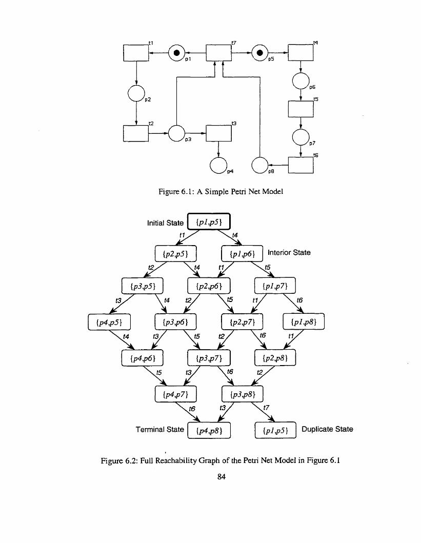
Figure 6.1 : A Simple Petri Net Model
State
f
Figure 6.2: Full Reachability Graph of the Petri Net Model in Figure 6.1
The initial state of the mode1 is represented as S,={pl,p5}, which means a token resides
in place pl and p.5, respectively, while ail other places are empty so that they are not shown in the
diagram. Several possible transition sequence paths will fom cycles in the p p h . For instance,
one of the occurrence sequences is: t4 + t l i t5 + t2 + r6 + r7. This occurrence sequence
leads from the initial state to the state marked Duplicate State, which actuaily is the same as the
initial state. There is one terminal state can be reached from the initial state, in which one token
resides in pIace p4 and p8 respectively.
In this thesis, the nodes of the reachability -pph from an exhaustive reachability search
are traverseci in a breadth-first fasiüon, i.e., siblings are processed before child nodes. A depth-
first search will cause run time stack over flow problem in the analysis of large protocols.
Duplicate States will never be re-investigated to Save time.
However, even for a small reachability graph, like the one in Figure 6.1, the construction
and investigation are tedious and error-prone- Thus it is obvious that we need to be able to
constnïct and investigate the reachability graphs by means of a cornputer. A user fnendly
graphitai integrated simulation tool, the Petri Net Modeler ( P m , was originated by Edwards,
Tavares and Meijer [ZO][2 11 and improved by Shao and Tavares [Sa]. Implemented using Java
with SWING technology, the PNM can be used in automated analysis of the Petri Net mode1 of
protocols. The functionaiity of the PNM has k e n introduced in Chapter 4.
It is aiso necessary to develop techniques by which we can construct reduced reachability
graphs without losing useful information. "Stubbom set" theory is one way to obtain such a
reduction. We have implemented and integrated this algorithm with the PNM in this thesis. The
stubborn set method will be further studied in the next section,
6.2 Reduced Reachability AnaIysis
6.2.1 Idea of Stubborn Sets
In theory, reachability anaiysis is a powerful formal method to anaIyze concurrent and distributed
systems. However, in practice. it suffers frorn the so called state space explosion problem. Due to
the combinatorid explosion of the inspected states, even for bounded nets, the state space of the
system c m be fa- too large with respect to time and cornputer resources (e.g., memory) needed to
inspect al1 states in the space.
Fominateiy, it is often the case that only the tennind states of a system are of interest.
Intuitively it seems that the terminal states of a system could be found without having to generate
d l reachable states of the system. Some methods [54] have been developed in which a reduced
space is generated so that no terminal state is lost.
The stubbom set method is based on the fact that some different interieaving of
concurrent transitions lead to the same state. So, redundant sequences may be cancelled. It takes
advantage of a lack of interaction between transitions in a concurrent or disûibuted system.
A stubborn set consists of some transitions of a net such that the set is in some sense
independent of the complement of the set. Stubbornness is a state-dependent property, Le. a set
cm be stubbom at some states while not stubburn at some others. A stubborn set is computed
separately in each state. It is minimal with respect to enabled transitions and certain other
conditions. Such minirnality is good since the nurnber of directions inspected usually affects the
number of states inspected during the verification of a aven property.
At a state, instead of firing al1 enabled transitions, only the transitions belonging to the
stubbom set are taken into account for the generation of the successor states. This method
reduces the state space of a system but preserves d l terminal states. The result of reachability
analysis usin; the stubbom set rnethod is a reduced reachability graph, which contains much
fewer interior states than the corresponding full reachability graph. It is important to notice that
the reduced reachability p p h c m be obtained directly, Le-. calculated without first constructing
the full reachability graph-
6.2.2 Constructing Stubborn Seb
A stubborn set is constructed in such a way that either the enabled or disabled condition of the
transitions in the stubbom set cannot be affected by any transitions outside of the stubbom set. In
other woràs, transitions that interact with each other must be included in the same stubborn set.
A stubbom set consists of disabled transitions and at least one enabled transition. More than one
stubbom set may exist at each state.
Suppose a CPN system cari be divided into stubborn sets and the complement of the sets
(i.e., environment), the principles of the stubborn theory [543 can be desaibed as follows: \
Pnizciple 1: If+[$) and M [ 4 , then +[or) and ~ M [ t d ,
where M is the rnarking where the system was partîtioned; t denotes any transition of the
stubborn set: and ostands for any transition sequence of the environment; 7 represents disabled
transitions. The pnnciple states that if the stubbom set has disabled transitions t at M (+[t)),
they cannot becorne enabled as a result of the operation of the environment, no matter how the
transitions of the stubborn set and the operation of the environment are interleaved, e.g., at or ta.
Principle 2 : If M [ t ) and M[d, then M[& and M[td.
The second principle expresses the fact that enabled transitions t inside of stubborn sets must still
be enabled after enabled transitions outside of stubborn sets fire in any sequence. 87
In [70], Zhao and Tavares defined two d e s associated with the principles described
above to construct stubborn sets. The rules prevent a disabled or enabled transition in a stubborn
set from changing its condition after a transition outside the stubbom set fires. Let t , denote any
transition inside of stubbom sets and taUr stand for any transition outside of stubbom sets. The
rules are defined as foilows:
Disable rule: Any transition t,, that shares its output place with any input place of a disabled
transition t , in a stubbom set rnust be included in this stubbom set.
Enable rule: Any transition t , that shares its input place with any input place of an enabled
transition t , in a stubborn set must be included in this stubbom set.
When transition t , that shares its output place with an input place of a disabled
transition t , fires, new tokens are generated and distributed in the output place of transition t ,
according to the post-conditions of transition firing r ü k s m q iz!isfy the pre-conditions of
iransition firing rules of transition t, . The change of the condition of the disabled transition t ,
may cause it to become enabled. According to the Disable d e , transition t , m u t belong to the
stubbom set so that the condition of a disabled transition in the stubbom set will change only by
a transition firing within the stubbom set.
Sirnilarly, if transition t,, shares an input place with an enabled transition t , , the firing
of transition t , will remove tokens from the shared input place. The change of the condition
may cause transition fin not to meet its pre-conditions of transition firing d e s and become
disabled. The Enable mle can be used in this case to include transition t, in the stubbom set to
make sure that the condition of an enabled transition in the stubborn set will remain unchanged
88
ifter firing transitions outside the stubbom set.
Since a stubborn set is searched at each encountered state, the cornputahon ought to be
fast. This c m be achieved by precomputing the topology of a CPN system. Constnicting
stubborn sets always starts with an enabled transition since each stubbom set must contain at
least one enabled transition. By applying the Enable rule to the enabled transition- the transition
outside which satisfies the condition will be included in the stubbom set. Then Enable nrle or
Disable nrle will be adopted recursively to each latest found transition to search for the next
transition which should be included in the stubborn set until no more transitions outside of the
stubbom set satisfy the condition of the Endde rule or Disable rule. A stubborn set can be
constructed by this means from an enabled transition.
Since, only one enabled transition within a stubbom set is fired to generate the next state
each time, it would appear that transition sequences staaing from other enabled transitions are
left uninvestigated. This is, however, not true since after firing the enabled m s i t i o n and
computing new stubbom sets, the paths are still possible and will eventually be examined.
The definition of a stubbom set implies that at al l non-terminal States there is at least one
stubbm set. As a matter of fact, the number of stubbom sets in a given state is as rnany as the
nwnber of enabled transitions at that state- It would usually be best to find a stubborn set with a
minimal number of enabled transitions. Although it may not always lead to the best possible
reduction, it is difficult to define a better simple goal. Figure 6.3 illustrates a procedure for
constnicting stubbom sets from a state.
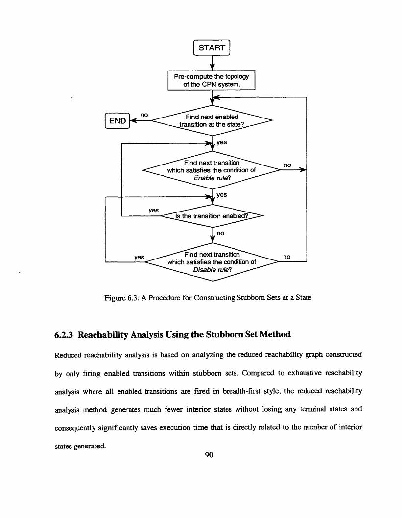
which satisfies the condition of
Figure 6.3: A hocedure for Constmcting Stubbom Sets at a State
6.2.3 Reachability AnaIysis Using the Stubbom Set Method
Reduced reachability anaiysis is based on analyzing the reduced reachability graph constructed
by only finng enabled transitions within stubbom sets. Compared to exhaustive reachability
anaiysis where al1 enabled transitions are fired in breadth-first style, the reduced reachability
analysis method generates much fewer intenor states without losing any terminal states and
consequently significantly saves execution time that is directly related to the number of interior
states generated. 90
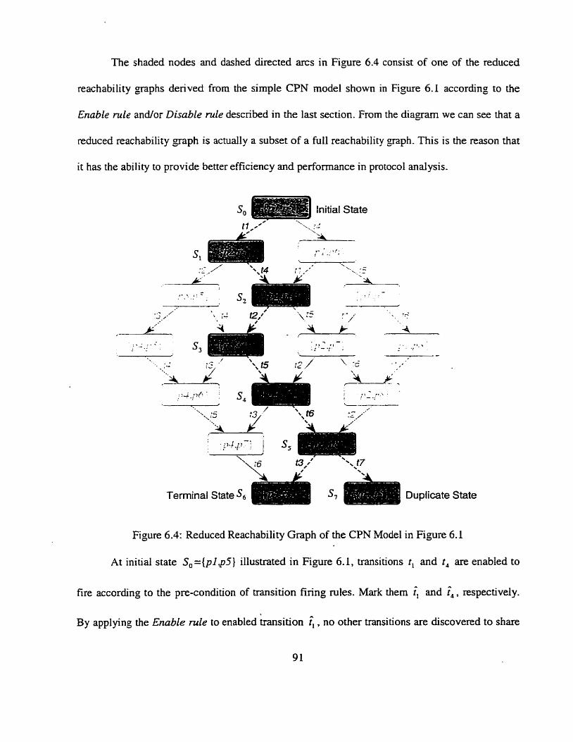
The shaded nodes and dashed directed arcs in Figure 6.4 consist of one of the reduced
reachability graphs derived from the simple CPN mode1 shown in Figure 6.1 according to the
Enable mle andfor Disable rule described in the last section. From the diagram we can see that a
reduced reachability graph is actually a subset of a full reachability "=ph- This is the reason that
it has the ability to provide better efficiency and performance in protocol andysis.
Ter
Figure 6.4:
ninal State Sa s, Duplicate State
Reduced Reachability Graph of the CPN Mode1 in Figure 6.1
At initial state S , = { p l , p S } illustrated in Figure 6.1, transitions t, and t, are enabled to
fire according to the pre-condition of transition firing rules. Mark them and î4, respectively.
By applying the Enable mle to enabled k s i t i o n î, , no other transitions are discovered to share
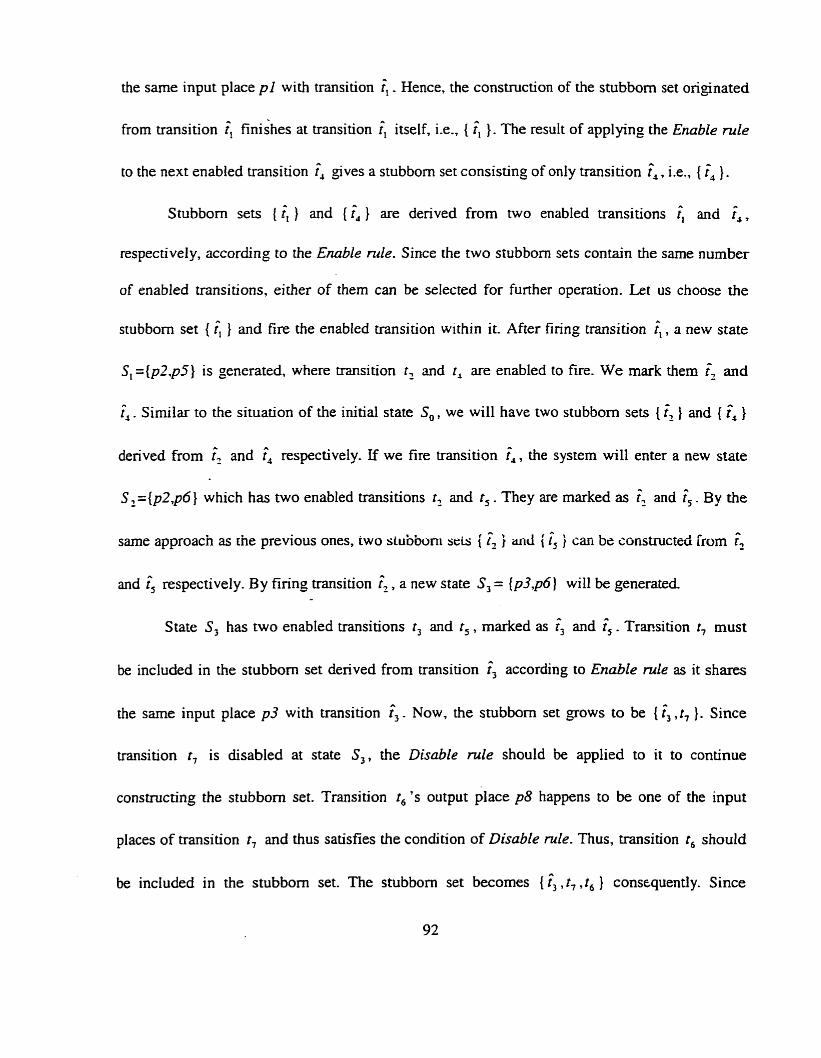
the same input place pl with transition il. Hence, the construction of the stubbom set originated
from transition finishes at transition ( itself, i-e., { î, 1 . The result of applying the Enable rule
to the next enabled transition î, gives a stubbom set consisting of only transition f, , i.e., { î, ).
Stubbom sets ( îl ) and { ?, ) are derived from two enabled transitions î, and i4,
respectively, according to the Enable rule. Since the two stubborn sets contain the same number
of enabled transitions, either of them can be selected for further operation. Let us choose the
stubbom set { î, } and fire the enabled transition within it. After finng transition i l , a new state
SI = { p z @ } is generated, where transition tZ and r , are enabled to fire. We mark them î, and
î, . Similar to the situation of the initial state S , , we will have two stubbom sets { 4 } and { î, }
denved from i2 and î, respectively. If we fire transition f,, the system will enter a new state
S, ={p2,p6} which has two enabled transitions t , and t , . They are marked as fz and î, . By the
same approach as rhe previous ones, cwo stubboni s r i s i & i aiid i f, i cari be constructed h m î2
and î, respectively. By finng transition î., a new state S, = {p3,p6} will be generated.
State S, has two enabled transitions t , and t , , marked as f, and î, . Trmsition t7 must
be included in the stubbom set derived from transition î, according to Enable d e as it shares
the same input place p3 with transition î,. Now, the stubbom set grows to be { î, ,t7 }. Since
transition t7 is disabled at state S,, the DisabLe rule should be applied to it to continue
constructing the stubborn set. Transition t , ' s output place p8 happens to be one of the input
places of transition r, and thus satisfies the condition of Disable rule. Thus, transition t, should
be included in the stubbom set. The stubbom set becomes { î, , t7 .t, } consequently. Since
92
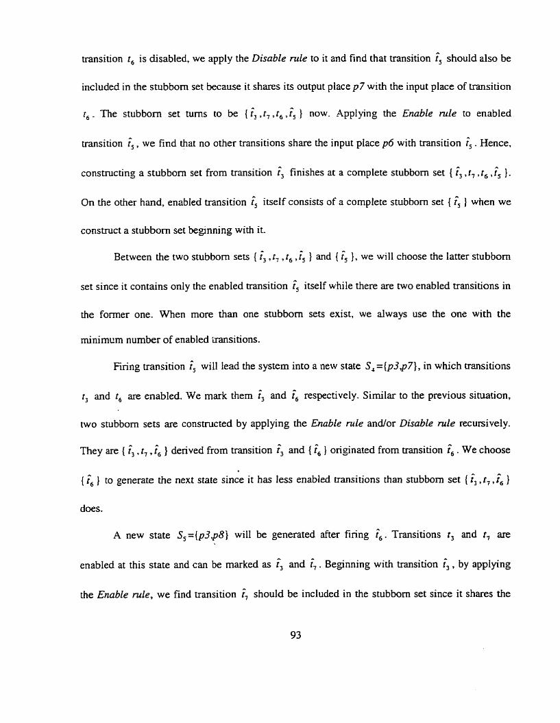
transition t , is disabled, we apply the Disable mle to it and find thai transition î5 should also be
included in the stubbom set because it shares its output place p7 with the input place of transition
t , . The stubborn set tums to be { î3 , t , .t, ,f, } now. Applying the Enoble nde to enabled
transition î5. w e find that no other transitions share the input place p6 with transition i, . Hence,
constructing a stubborn set from transition î, finishes at a complete stubborn set { î3 ,t , , t , ,î, }.
On the other hand, enabled transition î, itself consists of a complete stubbom set { f5 ) when we
constmct a stubborn set beginning with it.
Between the two stubbom sets { î, . 1, , t6 , î5 } and { î, } . we will choose the latter stubbom
set since it contains oniy the enabled transition î, itself while there are two enabled transitions in
the former one. When more than one stubborn sets exist, we always use the one with the
rninimun number of enabled 'iransitions.
Firing transition î, will lead the system into a new state S , =(p3 ,p7} , in which transitions
t3 and t , are enabled. We mark them < and î6 respectively. Sirniiar to the previous situation,
two stubborn sets are constnicted by applying the Enable rule andfor Disable mle recursively.
They are { î3 , t , , î, } denved from transition î, and { î, } onginated from transition . We choose
{ î, } to generate the next state since it has less enabled transitions than stubbom set { î,, t , ,& }
does.
A new state S5={p3,p8 j will be generated after firing î,. Transitions t3 and r, are
enabled at this state and c m be marked as < and î,. Beginning with transition f 3 , by applying
the Enable rule, we find transition î, should be included in the stubbom set since it shares the
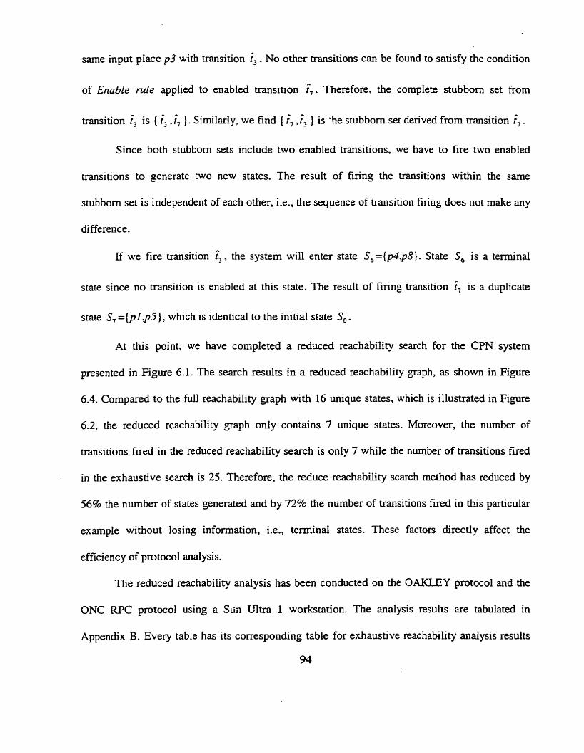
sarne input place p3 with transition î,. No other transitions c m be
of Enable mle applied to enabled transition î,. Therefore, the
found to satisfy the condition
complete stubborn set from
transition i3 is { î, , ). Sirnilarly, we find { f, ,< } is -he stubbom set derived from transition î, .
Since both stubborn sets include two enabled transitions, we have to fire two enabIed
transitions to generate two new states. The result of firing the transitions within the same
stubbom set is independent of each other, i-e., the sequence of transition firing does not make any
difference.
If we fire transition f,. the system will enter state S 6 = ( p 4 q 8 } . State S, is a terminal
state since no transition is enabled at this state. The result of firing transition î7 is a duplicate
state S, = { p l , p 5 ) , which is identical to the initial state S, .
At this point, we have completed a reduced reachability search for the CPN system
presented in Figure 6.1. The search results in a reduced reachability graph, as shown in Figure
6.4. Compared to the full reachability graph with 16 unique states, which is illustrated in Figure
6.2, the reduced reachability graph only contains 7 unique states. Moreover, the number of
transitions fired in the reduced reachability search is only 7 while the number of transitions fired
in the exhaustive search is 25. Therefore, the reduce reachability search method has reduced by
56% the number of states generated and by 72% the number of t~ansitions fired in this particular
example without tosing information, Le.. terminal states. These factors directly affect the
efficiency of protocol analysis.
The reduced reachability analysis has been conducted on the OAKLEY protocol and the
ONC RPC protocol using a Stin Ultra 1 workstation. The analysis results are tabulated in
Appendix B. Every table has its corresponding table for exhaustive reachability analysis results
94
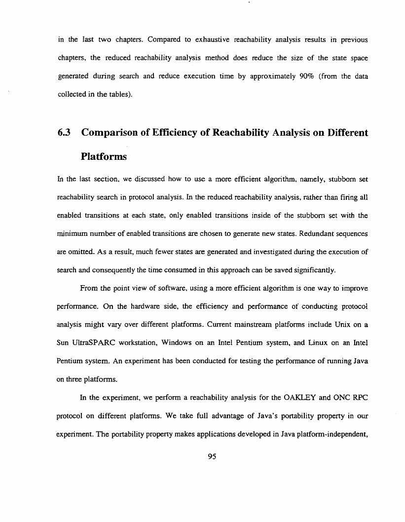
in the Iast two chaprers. Compared to exhaustive reachability analysis results in previous
chapters, the reduced reachability analysis method does reduce the size of the state space
generated during search and reduce execution tirne by approximately 90% (from the data
collected in the tables).
6.3 Cornparison of Efficiency of Reachability Analysis on Different
In the last section, we discussed how to use a more efficient algonthm, namely, stubbom set
reachability search in protocol andysis. In the reduced reachability analysis, rather than firing dl
enabled transitions at each state, only enabled transitions inside of the stubborn set with the
minimum number of enabled transitions are chosen to generate new states. Redundant sequences
are omitted. As a result, much fewer states are generated and investigated during the execution of
search and consequently the tirne consumed in this approach c m be saved significantly.
From the point view of software, using a more efficient algorithm is one way to improve
performance. On the hardware side, the efficiency and performance of conducting protocol
analysis might Vary over different platforms. Current mainstrearn platforms include Unix on a
Sun UlîraSPARC workstation, Windows on an Intel Pentium system, and Linux on an Intel
Pentium system. An experiment has been conducted for testing the peI-formance of running Java
on three platforms.
In the experiment, we perfonn a reachability analysis for the 0-Y and ONC RPC
protoc01 on different platforms. We take full advantage of Java's portability property in our
expenment. The portability propexty makes appiications developed in Java platfonn-independent,
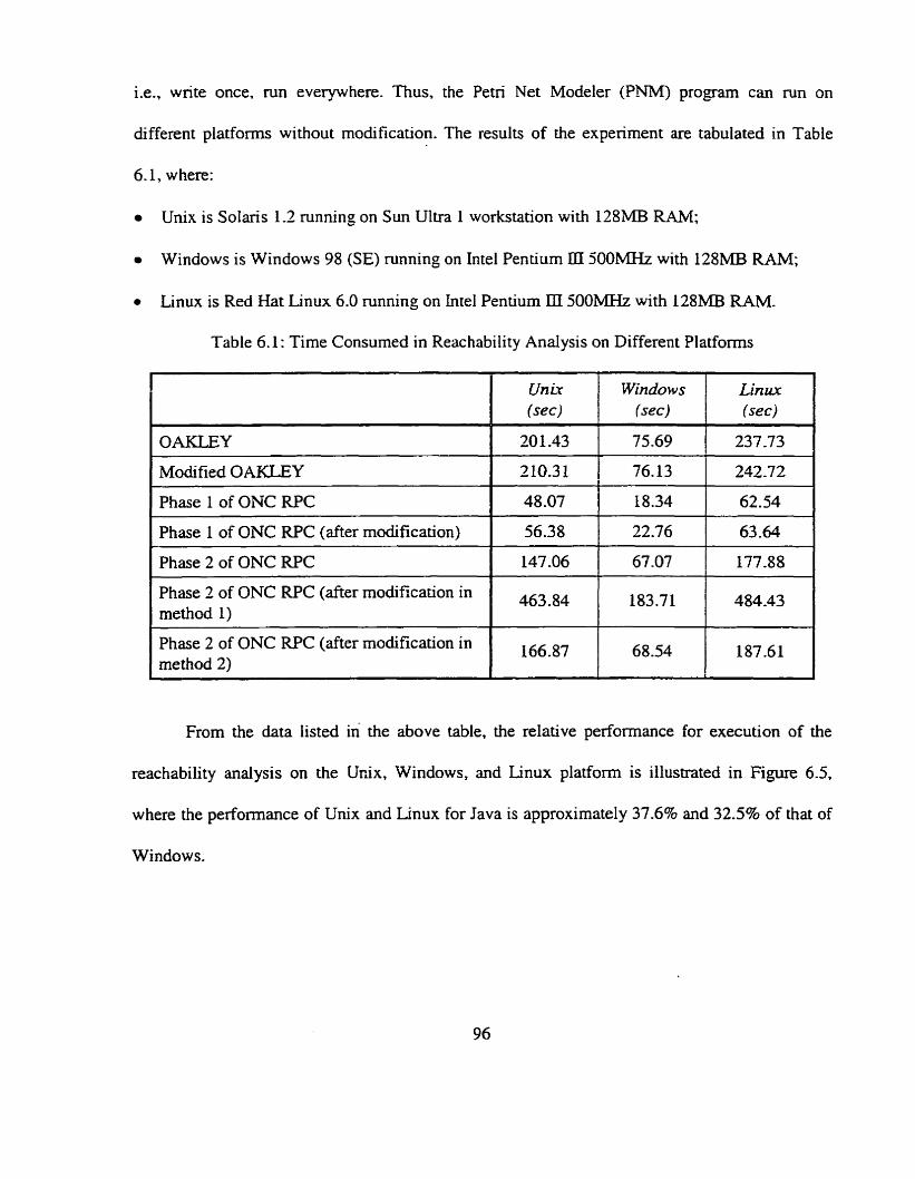
i.e., write once, run everywhere. Thus, the Petri Net Modeler (PNM) program can run on
different platforms without modification. The results of the experiment are tabulated in Table
6.1, where:
Unix is Solaris 1.2 running on Sun Ultra 1 workstation with 128MB RAM;
Windows is Windows 98 (SE) running on Intel Pentium ID S O O M H z with 128MB RAM;
r Linux is Red Hat Linux 6.0 running on Intel Pentiurn III 5OOM.z with 128MB RAM.
Table 6.1: Time Consumed in Reachability Analysis on Different Platforms
OAKLEY
Modified OAKLEY -
Phase 1 of ONC RPC
Phase 1 of ONC RPC (after modification)
Phase 2 of ONC RPC
Phase 2 of ONC RPC (afier modification in method 1) -
Phase 2 of ONC W C (after modification in method 2)
From the data listed in the above table, the relative performance for execution of the
reachability analysis on the Unix. Windows, and Linux platform is illustrated in Figure 6.5,
where the perfomance of Unix and Linux for Java is approximately 37.6% and 32.5% of that of
Windows.
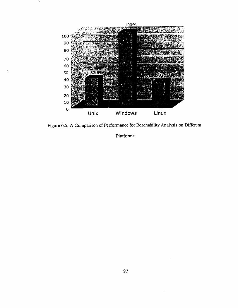
Figure 6.5:
Unix Windows Linux
A Cornparison of Performance for Reachability Analysis on
Platforrns
Different
Chapter 7
Conclusion
7.1 Discussion
The Internet has grown explosively during the past decade. With more and more sensitive
information transferred across the Internet, security becomes one of its major concems [2] [72].
Cryptographic protocols are extensively used to ensure data privacy, integrity, and authentication
~ 1 ~ 3 7 1 r m r 6 3 1 -
Although typically there are only a small nurnber of messages involved in cryptographic
protocols, they are notoriously error-prone. Cryptographic algorithms are incorporated into
cryptographic protocols. However, the security of the underlying algorithms does not guarantee
that a protocol meets its secunty objectives. The flaws might be related to the protocol design.
Some protocols were discovered to have flaws even after they had become standards [42][45].
The purpose of this thesis is to describe a forma1 methodology for the analysis of protocols and
use it to unveil potential flaws related to the protocol design based on the assumption that the
underl ying cryptographic algorithms are secure
Different methods can be applied in protocol analysis. Formal methods include state
machines [8], BAN logic [IO], and Algebra [38]. We analyze protocols based on Cotoured Petri
Net [7] methodology, due to its facility for graphical representation and precise specification
which provides visual analysis. This feature makes complex protocols more understandable so
that it becomes easier to find flaws.
We need to conduct protocol anaiysis by means of a computer since it is tedious and
error-prone to do manually. The Petri Net Modeler (PNM) is a user fnendy graphical automated

simulation tool originated by Edwards, Tavares, and Meijer in [20][21]. The procedure for
protocol analysis follows the foiiowing steps:
Study and fully understand the protocol under consideration;
Precisely translate the protocol specification into an executable Coloured Petri Nets model
using the P M ;
Explicitly constmct the Coloured Petri Nets model of an intmder in the PNM;
Conduct either exhaustive reachability analysis or stubborn set reachability analysis to
automatically constmct a reachability graph;
Examine d l terminal states in the reachability graph obtained from the previous step to
determine whether or not the protocol violates its security objectives;
If there exist insecure terminal states, a rnatrk equation solution [4][5] can be adopted to
discover a transition firing sequence path to identify possible attacks that could be performed
by the intmder;
ModiQ the CPN model of the flawed protocol in the PNM and repeat from step 4 until there
are no more insecure terminal states for this mode1 when attacked by this intmder.
Normally, each entity (including intmder) will be modeled as a separate Petri Net Object
(PNO). The first benefit of using a PNO is that it facilitates hierarchical modeling which gives
the designer and analyst the ability to control and reconfigure the levels of detail displayed;
another benefit is the possibility of reusing the PNOs designed for general purposes, like a class
library in Java. This methodology cm be used in modeling and analyzing not only cryptographic
protocols, but also other types of protocols. The common point is to examine the terminal states
to determine whether the objectives of a protocol are subverted or not.
7.2 Contributions
In this thesis we have implemented and intebated both exhaustive reachability analysis and
stubbom set reachability analysis into the PNM so that it has greater functionality of automated
protocol modeling and andysis. The terminal states can be examîned simply by the point-and-
click of a mouse. Another major improvement of the functionality of the PNM is the ability to
keep a record of al1 unique interior states within a reachability graph. These states are useful for
locating where the fiaws rnight be in the protocol analysis. Al1 progams in this thesis are coded
in Java. In [70], Zhao implemented a stand-aione program in C which can be used in protocol
analysis based on stubborn set theory.
By applying the CPN methodology to the analysis of the OAKLEY protocol, we have
found a flaw in it where the initiator and responder authenticate mutuaiIy without sharing the
same keying material. The flaw is caused by the lack of integrity of the cookies generated by the
initiator andor responder. In the ONC RPC protocol, one fiaw has k e n discovered in each
phase. Phase 1 of the protocol is vulnerable to an unknown key-share attack against the server
since it is possible that the client and server authenticate each other without knowing exactly
with whom they are dealing, although the intruder does not gain knowledge of any keys. This
flaw exists because the client does not provide integrity protection on nemame which is used to
identify the client to the server. In Phase 2 of the protocol, an intruder is able to impersonate a
client by replaying an obsolete conversation key to complete authentication with a server. This is
because there is no guarantee of the freshness of the conversation key. Different solutions have
been proposed to fix the tlaws discovered in the protocols.
The PNM has been run on different platforms without modification due to Java's
platform-independent property. The performance of running Java on different piatfoms has been
tested under fair conditions- Windows seems to run faster than Unix or Linux.
7.3 Future Work
We believe that protocol modeling and analysis based on the CPN methodology is promising. To
improve performance, the following areas could be of interest for further studying:
More protocols c m be modeled and analyzed using the CPN methodology in the PWM to
verify known flaws or discover unknown flaws in the protocols. This is the best way to
establish acceptance as a useful analysis approach.
More features c m be added to the P M , such as printing, moving a group of components
together, etc.
The stubbom set reachability analysis has k e n proved to be able to reduce the state space of
a system but preserves dl texminal States. However, no satisfactory theory has k e n presented
about the efficiency of the stubborn set method. The experïments made su far are not
sufficient to show how efficient the method is in practice. For both practical and theoretical
reasons, the method should be studied in a variety of practical cases.
It is unlikeiy that any of the analysis methods will surface as the complete, ailencompassing
solution for the analysis of protocols. Further study of the complementary strength of various
approaches will be useful to ensure effective and precise protocol analysis.
Glossary
AWT
CCITT
CITO
CPN
CTPN
DES
GUI
IETF
JDK
LAN
ONC
OPN
PN
PNM
PNO
PrT-nets
W C
WC
RSA
WAN
Abstract Windows Toolkit
Comité Consultatif International Téléphonique et Télégraphique
Communications and Information Technology Ontario
Coloured Petn Nets
Cryptographie Timed Petri Nets
Data Encryption Standard
Graphical User Interface
Intemet Engineering Task Force
Java Development Kit
Local Area Network
Open Network Computing
Ordinary Petri Nets
Petri Nets
Petri Net Modeler
Petri Net Object
Predicate-Transition nets
Request for Cornments
Remote Procedure Cal1
Rivest-S hamir-Adleman
Wide area Network
Appendix A
Some examples of the Petri Net Modeler Screen
Interface
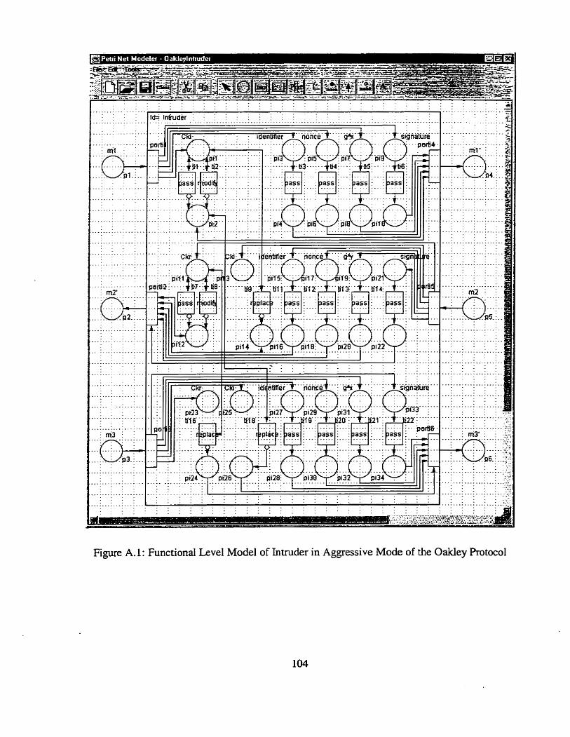
. - . . . . . . . . . . . . . . . .
. .
.................. : ~ 1 f ' -O-
. . . . . . . . Pl.. ..
Figure A.1: Functional Level Mode1 of Intruder in Aggressive Mode of the Oakley Rotocol
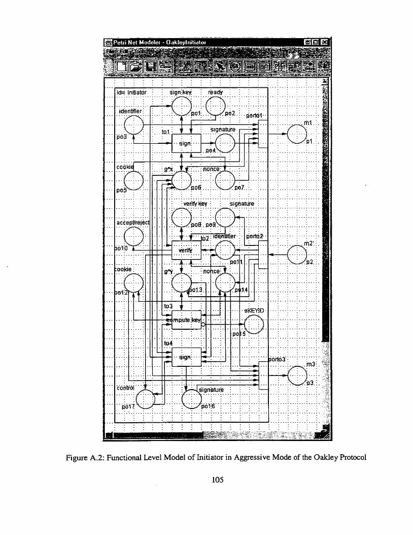
............. identifier i
...... . . .
Figure A.2: Functional Level Mode1 of Initiator in Aggressive Mode of the Oakley Protoc01
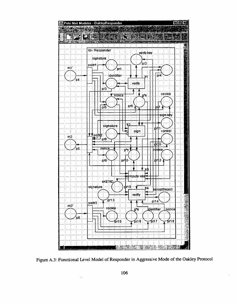
. . . r f r W : . ~ e & : k-
. . . . I I . . . . 1 -
Figure A.3: Functional Level Mode1 of Responder in Agpssive Mode of the Oakley Protocol
106
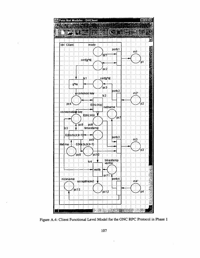
Figure A.4: Client Functional Level Model for the ONC RPC Protocol in Phase 1
107
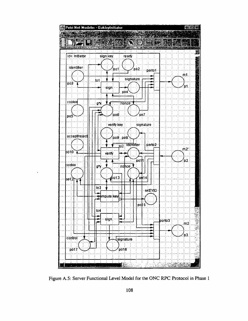
Figure AS: Server Functional Level Mode1 for the ONC RPC Protocol in Phase I
108
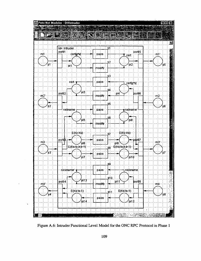
Figure A.6: Intruder Functional Level Mode1 for the ONC RPC Protocol in Phase 1
109
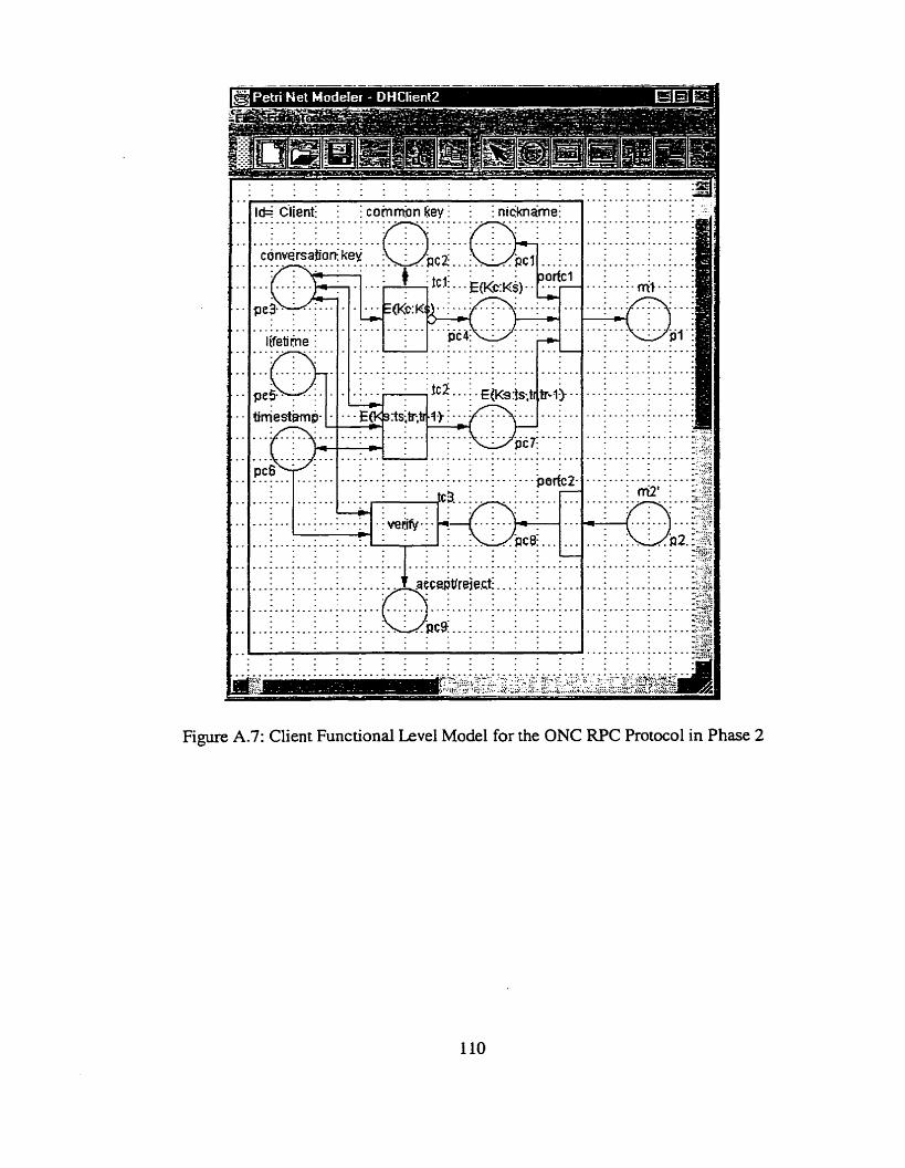
Figure A.7: Client Functional Level Mode1 for the ONC RPC Protocol in Phase 2
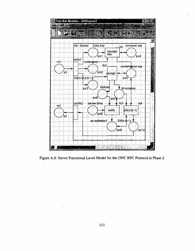
. . . . . . . . . . . . . . .
Id= Semi f(Kc:Ks) I :' i t,i &mmuR key
Figure A.8: Server Functional Level Mode1 for the ONC RPC Protocol in Phase 2
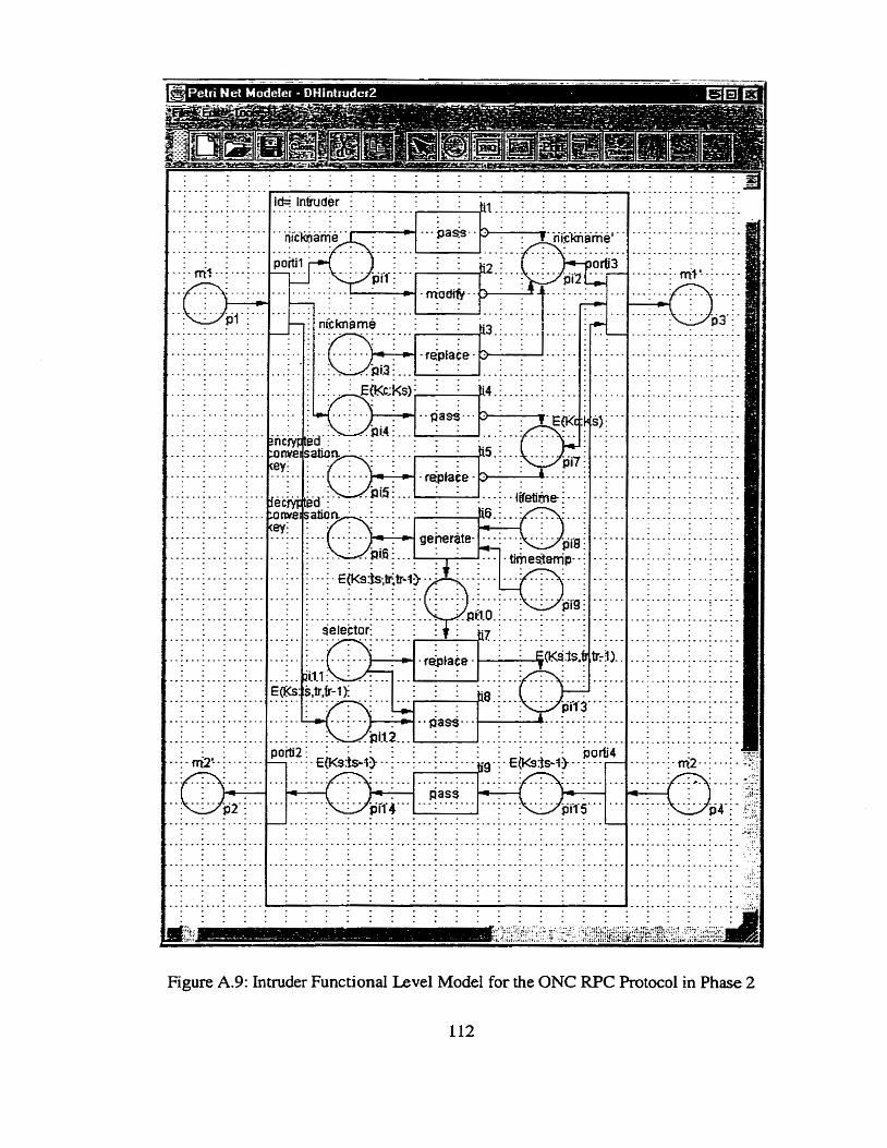
Figure A.9: Intruder Functional Level Mode1 for the ONC RPC Protocol in Phase 2
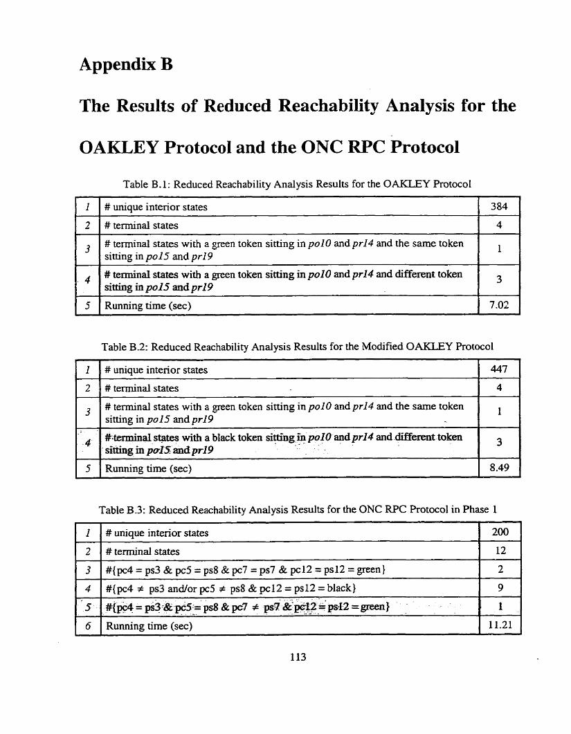
Appendix B
The Results of Reduced Reachability Analysis for the
OAKLEY Protocol and the ONC RPC Protocol
Table B. 1 : Reduced Reachability Analysis Results for the OAKLEY Protocol
# unique intenor States 384
# terminal states with a green token siaing in polo and pr14 and the sarne token sitting in po15 and pr19
Table B.2: Reduced Reachability Analysis Results for the Modified OAKLEY Protocol
4
5
1 1 # unique interior states
# terminal states with a green token sitting in pol O and pr14 and the sarne token sitting in pu15 and pr19
# terminal states with a green token sitting in polo and pr14 and different token Sitting in po15 and pr19
Running time (sec)
4 #*terminal s@tes with a black token Sitting ùi polo and prl4 and different -token sitting h poIS: andprl9
5 Running time (sec)
3
7 .O2
Table B.3: Reduced Reachability Analysis Results for the ONC RPC Protocol in Phase I
1 I 1 # unique interior states I 200 I 1 2 ( # terminai states I l2 I
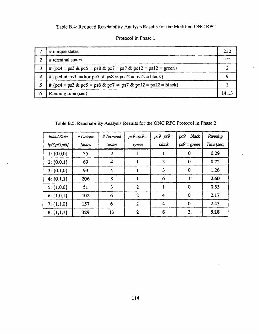
Table B.4: Reduced Reachability Analysis Results for the Modified ONC RPC
Protocol in Phase 1
# unique states 1 232
Table B.5: Reachability Analysis Results for the ONC W C Protocol in Phase 2
5
6
#{pc4=ps3&pc5=ps8&pc7 # ps7&pc12=ps12=black)
Running time (sec)
1
14.13
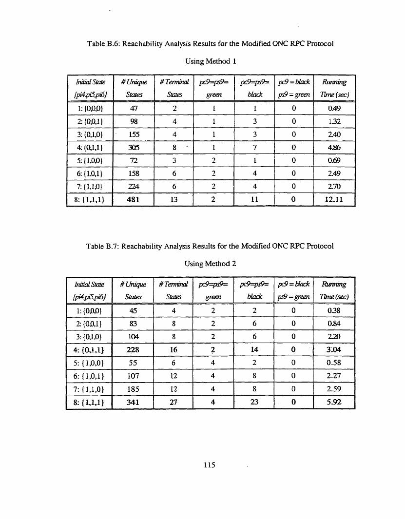
Table B.6: Reachability Analysis Results for the Modified ONC RPC Protocol
Using Method 1
Table B.7: Reachability Analysis Results for the Modified ONC RPC Rotocol
Using Method 2
hdidstcrr~
lpi4,piT,p16]
1: {O,O,O)
2: {0,Q71 }
3: {O,l,O)
4: {O, l , l )
5: { 1,0,0}
6: { l ,O, l}
7: {l,l,O)
8: { 1,lJ 1
# v h ü p
45
83
104
228
55
107
185
341
# T M
States
4
8
8
16
6
12
12
27 I E 23
@=pis%
green
2
2
2
2
4
4
4
4
pc9ps9= black
2
6
6
14
2
8
8
References
R. Anderson, "A Second Generation Wallet", ESORICS 92 Proceedings of ~ h e Second
European Symposium on Research in Compurer Secu+, pp. 4 1 1-4 18. S pringer-Verlag,
1992. R.J. Atkinson, 'Toward a More Secure Intemet", IEEE Computer. 18:57-6 1,
January 1997.
R.J. Atkinson, 'Toward a More Secure Internet", IEEE Computer, 18:57-6 1, January
1997.
T. Aura, "Modeling the Needharn-Schroeder Authentication Protoc01 with High Level Petri
Nets", Technical Repofl 8-14, Digital System Laboratory, Helsinki University of
Technology, Otaniemi, Finland Septemper 1995.
A. Basyouni, "Analysis of Wireless Cryptographie hotocols", Master's thesis, Queen's
University, Kingston, Ontario, Canada, 1997.
A. Basyouni, S E Tavares, "'New Approach to Cryptogrrphic Protocol Analysis Using
Coloured Petri Nets", Proc. of the Canadian Conferencb on Electrical and Cornputer
Engineering (CCECE' 97), pp. 334-337, St. John's, Newfoundland, 1997.
N. Behki, "An integrated approach to protocol design", Master's thesis, Queen's
University, Kingston, Ontario, Canada, 1990.
N. Behki and S.E. Tavares, "An htegrated Approach to Protocol Design", Proceedings of
the 1989 IEEE Pacific Rim Conference on Cornputers, Communications and Signal
Proceessing, pp. 244-248, May 1989.
G.V. Bochmann, "Finite State Description of Communication Protocols", Cornputer
Networks, 2:361-372,1978.
J. Burns, C. Mitchell, "A Security Scheme for Resource Sharing over a Network",
Cornputers and Security, Vol. 19, pp. 67-76, 1990.
1101 M. Burrows, M. Abadi, and R- Needham, "A Logic of Authentication", ACM Trans. On
Compufer Systerns, 8: 1 8-36, February 1990.
[ I l ] CClTT, CCZïTX.509, The Directory - An Authentication frarnework, 1988.
[12] A. Chiu, "Authentication Mechanisms for ONC WC", Intente? Engineering Task Force,
September 1999. http:/lwww .es.net/~ub/rfcs/rfc2695.txt
[13] D.E. Denning and G.M. Sacco, 'Timgestarnps in Key Distribution Protocols",
Cornmunicarions of the ACM, Vol. 24, No. 8, pp. 533-536, August 1981.
[ 141 D.E. Denning, Cryptography and Data Secudy, Addison-Wesley Publishing Company,
New York, 1982.
[l5] W. Difie, M.E. Hellman, "Pnvacy and Authentication: An Introduction to Cryptography",
Proceeding of the IEEE, 67(3):397-427, Mar. 1979.
[16] D. Dolev, A.C. Yao, "On the security of public key protocols", IEEE Transactions on
Infornation Theory, ïï-29(2): 198-208, March 1983.
[17] E.M. Doyle, "Automated Security Analysis of Cryptographic Protocols Using Coloured
Petri Nets", Master's thesis, Queen's University, Kingston, Ontario, 1996.
[18] E.M. Doyle, S.E. Tavares, H. Meijer, "Automated Security Analysis of Cryptographic
Protocols Using Coloured Petn Net S peci fications". Workrhop on Selected Areas in
Cryptography (SAC ' 951, Carleton University, Ottawa, Ontario, pp. 35-48, May 19%.
[19] E.M. Doyle, S.E. Tavares, H. Meijer, "Computer Analysis of Cryptographic Protocols
using Cotoured Peiri Nets", 18Lh Biennid Symposium on Communications Proceedings,
Queen's University, Kingston, Ontario, pp. 194- 199, June 1996.
[20] K. Edwards, "Cryptographic Protocol Specification and Analysis Using Coloured Petri
Nets and Java", Master's thesis, Queen's University, Kingston, Ontario. Canada, 1998.
[21] K. Edwards, S.E. Tavares, H. Meijer, "A Java Tool for Specification and Analysis of
Cryptograp hic Pro tocols Using Coloured Petri Nets", 1 qh Biennial Symposium on
Communications, pp. 403-407, Queen's University, Kingston, Ontario, May 1998.
[22] Federal Infornation Processing Standard 46 - the Data Encryptian Stundard, 1976.
[23] H.J. Genrich, "Predicate/Transition nets", Advances in Petn Nets 1986, pp. 207-247,
Springer-Verlag, 1986.
[24] L. Gong, R. Needharn, R. Yahalom, "Reasoning about Belief in Cryptographic Protocois",
Proceedings of the 1990 IEEE Symposium on Security and Privacy, pp. 234-148, TEEE
Cornputer Society Press., 1990.
[25] P. Gronberg, M. Tiusanen, K. Varpaaniemi, "PROD - a Predicate-Transition Net
Reachability Analysis Tool", Technical R e p o ~ , Digital Systems Laboratory, Helsinki
University of Technology, 1993.
1261 K. Jensen, Coloured Petri Nets, volume 1. Springer-Verlag, Berlin, 1992.
[27] K. Jensen, "Coloured Petn Nets", Advances in Petri Nets '86, pp. 248-299, Spnnger-
Veriag, 1987.
1281 K. Jensen, Coloured Pefn' Ners: Basic Concepts, Analysis Methads and Practicd Use,
S pnnger-Verlag Berlin Heidelberg New York, 1996.
[29] R. Kemmerer, C. Meadows, J. Millen, "Three Systems for' Cryptographic Protocol
Analysis", Journal ofCryptology, Vol. 7, No. 2, pp. 79-130, 1994.
[30] S. Kent and R. Atkinson, "IP Authentication Header", ~nteme t Engineering Tmk Force,
November 1998. htt~://www.es.net/~ub/rfcs/rfc2402.~t
[3 11 S. Kent and R. Atkinson, "IP Encapsulating Securiry Payload (ESP)", Interner Engineering
Task Force, November 1998. httv://www.es.net/pub/rfcs/rfc2406.txt
[32] G.S. Lee, J.S. Lee, "Petri Net Based Models for Specification and Analysis of
Cryptographic hotocols", Journal of Systems SofhYare, 37: 141- 159, 1997.
[33] G. Lowe, "An Anack on the Needham-Schroeder Public-Key Authentication Protocol",
Information Processing Letters, Vol. 56, pp. 13 1- 133, 1995.
[34] J.L. Massey, "An Introduction to Contemporary Cryptology", Proceedings of the IEEE,
Vol. 76, No. 5, pp. 533-549, May 1988.
[35] C. Meadows, "Fomal Verification of Cryptographic Rotocols: A Survey", Advances in
Cryptology-Asiacrypt '94, Lecture Notes in Computer Science 917, Springer-Verlag, pp.
133-150, 1995.
[36] C. Meadows, "Analyzing the Needham-Schroeder public key protocol: A cornparison of
two approaches", Pruc. ESORICS 96, Springer-Verlag, 1996.
[37] AJ. Menezes, P.C. van Oorschot, and S.A. Vanstone, Handbook of Applied Cryptography,
CRC Press, New York, 1997.
[38] M.J. Mema, Cryptographic Protoc; Is, PIiD thesis, Georgia Institute of Technology, 1983.
1391 J. Millen, C. Neuman, J. Schiller, J. Saltzer, "Kerberos Authentication and Authorization
system", Project Atlzena Technical Plan, Section E.2. i ., M.LT., MA., 1987.
[40] J. Millen, 'The Interrogator Modei", Proceedings of the 1995 IEEE Symposium on Securiry
and Privucy, pp. 25 1-260, IEEE Computer Society Press., 19%.
[41] J. Millen, S. Clark, S. Freedrnan, 'The Interrogator: Protocol Security AnalysisT7, IEEE
Transuctions on Softwnre Engineering, Vol. 13, NO. 2, 1987.
[42] J. Moore, "Protocol Failures in Cryptosystems", Proc. of the IEEE, Vo1.76, NOS, pp. 597,
Majj 1298.
[43] CM. Morton, "A Modular Approach to Modeling Cryptographic Protocols Using Petri
Nets", Master's thesis, Queen's University, Kingston, Ontario, Canada, 1993.
1441 C.M. Morton, L.C. Robart, S.E. Tavares, "Analyzing Cryptographic Protocols Using A
Modular Petri Net Approach", 1 Th Biennial Symposium on Communications Proceedings,
pp. 473-4225, Queen's University. Kingston, Ontario, May i994
[45] R. Needham, M. Schroeder, "Authentication revisited", Operaring Sysrems Roriao, Vo1.31,
No. 1, July 1987.
[46] R.M. Needharn, M.D. Schroeder, "Using Encryption for Authentication in Large Networks
of Cornputers", Commrtnications of the ACM, Vol. 21, No. 12, pp. 993-999, December
1978.
[47] B.B. Nieh, "Modeling and analysis of cryptographic protocols using Pem Nets", Master's
thesis, Queen's University, Kingston, Ontario, Canada, 1992.
[48] B.B. Nieh, S.E. Tavares, "Modeling and analyzing cryptographic protocols using Petri
Nets", Advances in Cryptology, Ptoc. of AUSCRYPT' 92, pp. 275-295, Springer-Verlag,
1993.
[49] R. Oppliger, "htemet Securïty enters the Middle Ages", Cornputer 28, pp. lm-101, 1995.
[50] H. Orrnan, "The Oakley Key Determination Protocol", Intemet Engineering Tmk Force,
November 1998. hn~:llwww.es.netlpub/rfcslrfc2412,txt
[51] D. Otway, O. Rees, "Efficient and timely mutud authentication", ACM Operating Systems
Review, 21(1), pp. 840,1987.
[52] G. Pal, "Verification of the iKP farnily of secure electronic payrnent protocols",
hrtp:/heb.nzir.edz&npaW/ilcp/venfv ib.hmi1, 1996.
3 1 C.A. Petri. Kornmunikntion mit Automaten, PhD thesis, Institut fur Instrumentelle
Mathematik, Schriffen des IIM, 1962.
[54] M. Rauhamaa, "A Comparative Smdy of Methods for Efficient Reachabiiity Anaiysis",
Digital system Laboratory Report A 14, pp. 6 1, Helsinlci University of Technology, 1990.
[55] R. Rivest, A. Shamir and L. Adleman. "A Method for Obtaining Digital Signatures and
Public-Key Cryptosystems", Communications of the ACM, 21(2), pp. 120-126, Febmary
1978. I
1561 A-D. Rubin, P. Honeyman, ''Formal Methods for the Analysis of Authentication
Rotocols", ClTI Technical Report 93- 7, Center for Information Technology Integration,
University of Michigan, November 1993.
[57] B. Schneier, Applied Cryptography, John Wiley and Sons Inc, New York, 1996.
[58] Y 9. Shao, "Specification and Analysis of Intemet Cryptographic Rotocols Using A Petri
Net Modeler", Master's thesis, Queen's University, kingston, Ontario, Canada, 1999.
[59] S.P. Shieh, W.H. Yang, "An Authentication and Key Distribution System for Open
Network S ystems", ACM Operating System Review, Vol. 30, No. 2, pp. 32-41, 1996.
[60] G. Simmons, 'Xow to Selectively Broadcast a Secret", Proceedings of the 1985 IEEE
Symposizun on Securiiy and Privacy, EEE Computer Society Press., 1985.
[6 11 E. Snekkenes, "Explorhg the BAN approach to protocol analysis", Proc. IEEE Symposium
on Research in Securiry and Privacy, pp. 17 1 - 18 1.199 1.
[62] W. S tallings, Cryptography and Network Security: Pnnciples and Practice, Upper Saddle
River, N.J. : Prentice Hall, 1999.
[63] D.R. Stinson, Cryptography nieory and Practice, CRC Press, 1995.
[64] P. Syverson, "Adding time to a logic of authentication", Proc. First ACM Conference on
Computer and Communications Security, pp. 97- 10 1, ACM Press, 1993.
[65] W. Tuchman, Hellman Presents No-Shoacut Solutions tu DES, IEEE Spectrum, M y 1979.
[66] M.J. Toussaint. "Deriving the comptete knowledge of participants in cryptographic
protocols", Ahances in Cryptology-Crypto '91. pp. 24-43, Springer-Verlag, 199 1.
[67] M. J. Toussaint, ' 'Formal verifkation of probabilistic properties in cryptographic protocols",
Lecture Notes in Cornputer Science #739, pp. 412426,1992.
[68] A. Vahari, "Stubbom Sets for Reduced State Space Generation", Advances in Petri Nets'
90, pp. 491-5 15, L e c m Notes in Computer Science 483, springer-Verlag, Berlin, 1990.
[69] A. Valmari, "State Space Generation: Efficiency and Racticaiity", PhD. thesis, Tampere
University of Technology, Finland, Publications 55,1988.
[70] W.M. Zhao. "'Efficient Analysis of Cryptographie Protocols in Wireless Communication
Systems", Master's thesis, Queen's Univemity, Kingston, Ontario, Canada, 1997.
[71] WM. Zhao, SE. Tavares, "An Analysis of MSAT Secwity Rotocols using Coloured Petri
Nets", Technical Report, Department of Elecnical and Computer Engineering, Queen' s
University , April 1 997.
[72] P.R. Zimmermann, "Cryptography for the Intemet", Scientzfzc Amencan, pp. 110-1 15,
October 1998.