Embed Size (px)
Citation preview
Eindhoven University of Technology
MASTER
Automated rule checking for in-house BIM norms of building models
Ayyadurai Charles, V.R.D.
Award date:2016
DisclaimerThis document contains a student thesis (bachelor's or master's), as authored by a student at Eindhoven University of Technology. Studenttheses are made available in the TU/e repository upon obtaining the required degree. The grade received is not published on the documentas presented in the repository. The required complexity or quality of research of student theses may vary by program, and the requiredminimum study period may vary in duration.
General rightsCopyright and moral rights for the publications made accessible in the public portal are retained by the authors and/or other copyright ownersand it is a condition of accessing publications that users recognise and abide by the legal requirements associated with these rights.
• Users may download and print one copy of any publication from the public portal for the purpose of private study or research. • You may not further distribute the material or use it for any profit-making activity or commercial gain
Take down policyIf you believe that this document breaches copyright please contact us providing details, and we will remove access to the work immediatelyand investigate your claim.
Download date: 24. May. 2018
Eindhoven University of Technology
Master of Construction Management & Engineering
___________________________________________________________________
Automated Rule Checking for in-house BIM Norms of
Building Models
_______________________________________________________________
By
V.R.D. Ayyadurai Charles (0923390)
17th August 2016
______________________________________________________________
Supervisors Dr. dipl. ing. Jakob Beetz
Mr. Chi Zhang
Graduation Professor Prof.dr.ir. Bauke de Vries
External Supervisors Mr. Joost van d Koppel
_______________________________________________________________
Hendriks Bouw en Ontwikkeling, Oss, The Netherlands
Eindhoven University of Technology, Eindhoven, The Netherlands

ii

iii
Acknowledgement Foremost, I would like to express my sincere gratitude to my advisor Dr. dipl. ing. Jakob Beetz
for the continuous support of my master thesis, for his patience, motivation, enthusiasm, and
immense knowledge. His guidance helped me in all the time of research and writing of this
thesis. I could not have imagined having a better advisor and mentor for my master thesis.
Besides my advisor, I would like to thank the rest of my other supervisors: Mr. Chi Zhang and
Mr. Thomas Krijnen, for their encouragement, and technical support.
I would like to Prof.dr.ir. Bauke de Vries chairperson for my graduation committee.
My sincere thanks also goes to Mr. Joost van de Koppel (BIM Manager) for offering me the
Master thesis internship opportunities in Hendriks Bouw en Ontwikkeling located in Oss, The
Netherlands.
I would like to thank my fellow student friends at Eindhoven University of Technology for the
fun, support and encouragement throughout the whole years of my master program.
Last but not least, I would like to thank the God almighty and my parents, Charles and Grace
Shanthi for their blessings and support through my life.
Sincerely,
V.R.D.Ayyadurai Charles
IV
Summary Rules are written in language by the experts of the field. In the construction industry the rules
and regulations are called building standards. These rules are often published by the public
legal bodies in both national and international level. Professional clients have their own in-
house rules and regulations in order to maintain a smooth work flow with the supply chain
partners throughout the building process. Rule checking for building design is conducted
universally to check the stability of building design to improve the quality and safety of that
building. Traditionally, building designs in 2D are checked against the building standards
manually. This traditional rule checking process is more complex and time consuming. With the
advancement in Building Information Modeling (BIM) in construction industry over these years
makes the rule checking process into automated. BIM has brought an integration of building
information and its 3D visualization of objects into building models.
In the past decade, there are many new automated rule checking systems and tools being
developed. Some state of the art technologies in the field of automated rule checking process
are CORENET, Solibri Model Checker, EDM model checker and SMART-Code.These technologies
having their own limitations in terms of interoperability, extendibility and logical compilation
check. As we know, rules and regulations are changing time to time based on new inventions in
the construction industry to enhance the quality and safety of the building. Investing on the
commercial tools like Solibri Model Checker would increase the investment cost in a project and
reduce the overall profit.
This research focuses on avoiding above limitations of an automated rule checking tools for
building designs. Semantic web technology and Linked data approach gives the solutions to
overcome these limitations. Using the Semantic web technology: schemas, instances, and the
rules can be defined in a common frame with the same language or format, know as Resource
Description Framework (RDF). Linking of diverse information gives an opportunity to show
potential interrelationship among diverse sources of information in a building project.
This graduation project is collaborated with Hendriks Bouw en Ontwikkeling located in Oss, The
Netherlands. Hendriks have their own in-house BIM norm know as the HBO BIM norm. The
models are checked and validated using Solibri Model Checker (SMC). The above mentioned
limitations of SMC are reflected in the process of rule checking in the company. Still few in-
house rules are checked manually and it is time consuming and needs extra effort for the BIM
manager to check the design. This project focuses on developing an automated rule checker for
in-house BIM norms based on Linked data approach.
Initially, the rules are selected from the HBO BIM norm based on company’s preference(s) and
academic perspective. Rules are categorized into two namely property rules and geometrical
rules. The building design and construction data are converted into a common data format
know as RDF. Rules written in natural language are formalized using SPARQL query language.
V
The use case models are tested against the rules and end results are reported in three
dimensional view. Finally, the research questions stated for this graduation project are
answered and recommendations are given for future development and research.
This prototype automated rule checker based on Linked data approach proves that this
technique is able to solve the limitations and barriers in the current rule checking process of the
company. This automated rule checker has the following capabilities.
The ability to query and check the building model without expensive and heavy
technical or programming requirements.
The ability to perform checks on both the properties and geometry of the building
model.
The ability to visualize the results in a three dimensional view.
This rule checker can be shared among the stakeholders to check the design by
themselves before sending it to other stakeholders. It reduces the iterative
process of rule checking.
VI
Abstract In recent years the Architectural, Engineering & construction (AEC) industry relies on different
automated tools to check and validate the building design. However most of the tools are lack
in interoperability, extendibility and logical compilation checks. Moreover these tools are
programmed with high level programming languages. By avoiding these limitations an
automated tool is beneficial for rule checking process. Semantic web technology and Linked
data approach fulfill the above aim. This graduation project focuses on developing, an
automated rule checker based on Linked data approach for the in-house BIM norms. The
architectural design and construction data are converted into common data format know as
Resource Description Framework (RDF). The rules form the in-house BIM norm is formalized
using SPARQL query language. The results of this automated rule checking process are
visualized in three dimensional view using Python libraries and modules know IfcOpenShell and
python OpenCasCade. Once this in-house rule checker is developed, the end user can check
multiple of design and 3D visualization of results helps for effective communication among the
stakeholders involved in the construction project. It addition this it reduces the cost on
investing in a commercial rule checking tools.
Keywords: Rule checking, in-house BIM norm, Linked data, RDF, SPARQL and IfcOpenShell

VII
Contents Acknowledgement ....................................................................................................................................... iii
Summary ...................................................................................................................................................... IV
Abstract ........................................................................................................................................................ VI
Chapter-1 ...................................................................................................................................................... 1
1 Introduction ............................................................................................................................................... 1
1.1 Research Overview ....................................................................................................................... 2
1.1.1 Current process ............................................................................................................................ 2
1.1.2 Problem analysis .......................................................................................................................... 5
1. 2 Research question .............................................................................................................................. 5
1.3 Research approach........................................................................................................................ 6
1.3.1 Rule and Requirement Interpretation ......................................................................................... 6
1.3.2 Building Model Preparation ......................................................................................................... 6
1.3.3 Rule Execution .............................................................................................................................. 7
1.3.4 Reporting the Result .................................................................................................................... 7
1.4 Expected results .................................................................................................................................. 7
Chapter-2 ...................................................................................................................................................... 9
2 Glossary ...................................................................................................................................................... 9
Chapter-3 .................................................................................................................................................... 13
3 Literature Review ..................................................................................................................................... 13
3.1 Building Information Modeling (BIM) and Industry Foundation Classes (IFC) ................................. 13
3.2 Linked Data and Semantic web ......................................................................................................... 14
3.3 BIM, Linked Data and Semantic web ................................................................................................ 15
3.4 Rules and Regulation ........................................................................................................................ 16
3.5 Automated Rule Checking and Linked Data ...................................................................................... 17
3.6 Conculsion ......................................................................................................................................... 19
Chapter-4 .................................................................................................................................................... 21
4 Methodology ........................................................................................................................................ 21
4.1 Research model................................................................................................................................. 21
4.1.1 In-House Rules ........................................................................................................................... 21
4.1.2 Formalized the rules .................................................................................................................. 23
4.1.3 Convert data to RDF ................................................................................................................... 24
VIII
4.1.4 Execution and Visualization ....................................................................................................... 24
4.2 Conceptual Frame work .................................................................................................................... 24
Chapter-5 .................................................................................................................................................... 25
5 Implementation ....................................................................................................................................... 25
5.1 Introduction ...................................................................................................................................... 25
5.2 Implementation for Property Rule Checking .................................................................................... 26
5.3 Programming steps for Property Rule Check .................................................................................... 28
5.3.1 Import Libraries and Modules .................................................................................................... 28
5.3.2 SPARQL Query: Property Rule Check ......................................................................................... 29
5.3.3 Visualization: Property Rule Check ............................................................................................ 30
5.4 Results of Property Rule Checking .................................................................................................... 30
5.5 Implementation of Geometrical Rule Checking ................................................................................ 33
5.6 Programming steps for Geometric Rule checking ............................................................................ 34
5.6.1 Import libraries and IFC model .................................................................................................. 34
5.6.2 Calculating wall dimensions ....................................................................................................... 34
5.6.3 Creating a RDF graph ................................................................................................................. 35
5.6.4 SPARQL query: Geometrical Rule checking ................................................................................ 36
5.6.5 Visualization: Geometrical Rule checking .................................................................................. 36
5.7 Result of Geometrical Rule Checking ................................................................................................ 37
5.8.1 Assumptions ............................................................................................................................... 39
5.8.2 Limitations .................................................................................................................................. 39
5.8.3 Recommendation ....................................................................................................................... 39
Chapter-6 .................................................................................................................................................... 41
6 Conclusion ................................................................................................................................................ 41
6.1 Answer(s) to research questions ...................................................................................................... 41
6.2 Social Relevance ................................................................................................................................ 43
Bibliography ................................................................................................................................................ 45
Appendix- A ................................................................................................................................................. 49
Appendix-B .................................................................................................................................................. 61
Appendix-C .................................................................................................................................................. 65
IX
Figure 1 Overall Rule Checking process report format ................................................................................. 4
Figure 2 Current rule checking process (BPNM) ........................................................................................... 4
Figure 3 Research approach .......................................................................................................................... 6
Figure 4 Conceptual Frame Work ............................................................................................................... 21
Figure 5 Xella Combinations in IFC file (screen shot) .................................................................................. 23
Figure 6 Work flow diagram of Property Rule Check .................................................................................. 26
Figure 7 Wall property combinations in RDF triple format ........................................................................ 27
Figure 8 Programming sequence for Property Rule Checking .................................................................... 28
Figure 9 SPARQL Query for Property rule check ......................................................................................... 29
Figure 10 Output of the SPARQL query for property rule check in TopBraid Composer ........................... 30
Figure 11 Violated wall Properties in 3D view ............................................................................................ 31
Figure 12 Walls other than limestone walls as in green ............................................................................. 32
Figure 13 Highlighting non-limestone walls in green using "If “condition ................................................. 32
Figure 14 Work flow of Geometrical Rule Checking ................................................................................... 33
Figure 15 Programming sequence for Geometrical rule checking ............................................................. 34
Figure 16 RDF graph with wall dimensions ................................................................................................. 35
Figure 17 Query to find the walls longer than 12 meters ........................................................................... 36
Figure 18 Walls longer than 12 meters highlighted in red ......................................................................... 37
Figure 19 Query modified to check limestone walls smaller than 12 ......................................................... 37
Figure 20 Geometrical rule checking conducted using complex model ..................................................... 38
Figure 21 Limestone walls smaller than 12 meters are shown in green .................................................... 38

X
1
Chapter-1
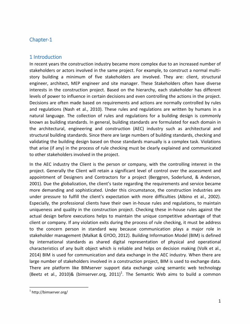
1 Introduction In recent years the construction industry became more complex due to an increased number of
stakeholders or actors involved in the same project. For example, to construct a normal multi-
story building a minimum of five stakeholders are involved. They are: client, structural
engineer, architect, MEP engineer and site manager. These Stakeholders often have diverse
interests in the construction project. Based on the hierarchy, each stakeholder has different
levels of power to influence in certain decisions and even controlling the actions in the project.
Decisions are often made based on requirements and actions are normally controlled by rules
and regulations (Nash et al., 2010). These rules and regulations are written by humans in a
natural language. The collection of rules and regulations for a building design is commonly
known as building standards. In general, building standards are formulated for each domain in
the architectural, engineering and construction (AEC) industry such as architectural and
structural building standards. Since there are large numbers of building standards, checking and
validating the building design based on those standards manually is a complex task. Violations
that arise (if any) in the process of rule checking must be clearly explained and communicated
to other stakeholders involved in the project.
In the AEC industry the Client is the person or company, with the controlling interest in the
project. Generally the Client will retain a significant level of control over the assessment and
appointment of Designers and Contractors for a project (Berggren, Soderlund, & Anderson,
2001). Due the globalization, the client’s taste regarding the requirements and service became
more demanding and sophisticated. Under this circumstance, the construction industries are
under pressure to fulfill the client’s expectation with more difficulties (Albino et al., 2002).
Especially, the professional clients have their own in-house rules and regulations, to maintain
uniqueness and quality in the construction project. Checking these in-house rules against the
actual design before executions helps to maintain the unique competitive advantage of that
client or company. If any violation exits during the process of rule checking, it must be address
to the concern person in standard way because communication plays a major role in
stakeholder management (Malkat & GYOO, 2012). Building Information Model (BIM) is defined
by international standards as shared digital representation of physical and operational
characteristics of any built object which is reliable and helps on decision making (Volk et al.,
2014) BIM is used for communication and data exchange in the AEC industry. When there are
large number of stakeholders involved in a construction project, BIM is used to exchange data.
There are platform like BIMserver support data exchange using semantic web technology
(Beetz et al., 2010)& (bimserver.org, 2011)1. The Semantic Web aims to build a common
1 http://bimserver.org/
2
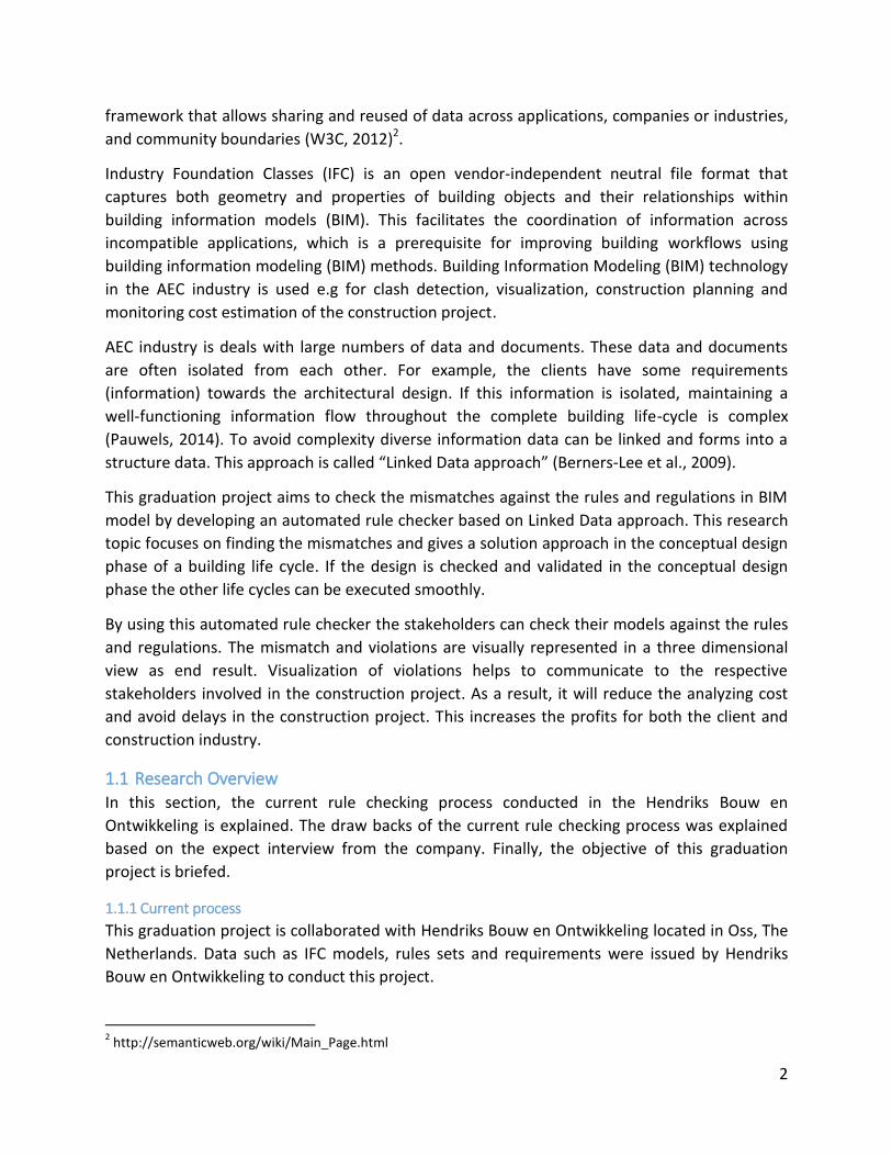
framework that allows sharing and reused of data across applications, companies or industries,
and community boundaries (W3C, 2012)2.
Industry Foundation Classes (IFC) is an open vendor-independent neutral file format that
captures both geometry and properties of building objects and their relationships within
building information models (BIM). This facilitates the coordination of information across
incompatible applications, which is a prerequisite for improving building workflows using
building information modeling (BIM) methods. Building Information Modeling (BIM) technology
in the AEC industry is used e.g for clash detection, visualization, construction planning and
monitoring cost estimation of the construction project.
AEC industry is deals with large numbers of data and documents. These data and documents
are often isolated from each other. For example, the clients have some requirements
(information) towards the architectural design. If this information is isolated, maintaining a
well-functioning information flow throughout the complete building life-cycle is complex
(Pauwels, 2014). To avoid complexity diverse information data can be linked and forms into a
structure data. This approach is called “Linked Data approach” (Berners-Lee et al., 2009).
This graduation project aims to check the mismatches against the rules and regulations in BIM
model by developing an automated rule checker based on Linked Data approach. This research
topic focuses on finding the mismatches and gives a solution approach in the conceptual design
phase of a building life cycle. If the design is checked and validated in the conceptual design
phase the other life cycles can be executed smoothly.
By using this automated rule checker the stakeholders can check their models against the rules
and regulations. The mismatch and violations are visually represented in a three dimensional
view as end result. Visualization of violations helps to communicate to the respective
stakeholders involved in the construction project. As a result, it will reduce the analyzing cost
and avoid delays in the construction project. This increases the profits for both the client and
construction industry.
1.1 Research Overview In this section, the current rule checking process conducted in the Hendriks Bouw en
Ontwikkeling is explained. The draw backs of the current rule checking process was explained
based on the expect interview from the company. Finally, the objective of this graduation
project is briefed.
1.1.1 Current process
This graduation project is collaborated with Hendriks Bouw en Ontwikkeling located in Oss, The
Netherlands. Data such as IFC models, rules sets and requirements were issued by Hendriks
Bouw en Ontwikkeling to conduct this project.
2 http://semanticweb.org/wiki/Main_Page.html
3
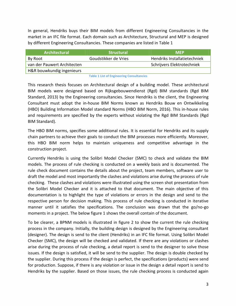
In general, Hendriks buys their BIM models from different Engineering Consultancies in the
market in an IFC file format. Each domain such as Architecture, Structural and MEP is designed
by different Engineering Consultancies. These companies are listed in Table 1
Architectural Structural MEP
By Root Goudstikker de Vries Hendriks Installatietechniek
van der Pauwert Architecten Schrijvers Elektrotechniek
H&R bouwkundig ingenieurs Table 1 List of Engineering Consultancies
This research thesis focuses on Architectural design of a building model. These architectural
BIM models were designed based on Rijksgebouwendienst (Rgd) BIM standards (Rgd BIM
Standard, 2013) by the Engineering consultancies. Since Hendriks is the client, the Engineering
Consultant must adopt the in-house BIM Norms known as Hendriks Bouw en Ontwikkeling
(HBO) Building Information Model standard Norms (HBO BIM Norm, 2016). This in-house rules
and requirements are specified by the experts without violating the Rgd BIM Standards (Rgd
BIM Standard).
The HBO BIM norms, specifies some additional rules. It is essential for Hendriks and its supply
chain partners to achieve their goals to conduct the BIM processes more efficiently. Moreover,
this HBO BIM norm helps to maintain uniqueness and competitive advantage in the
construction project.
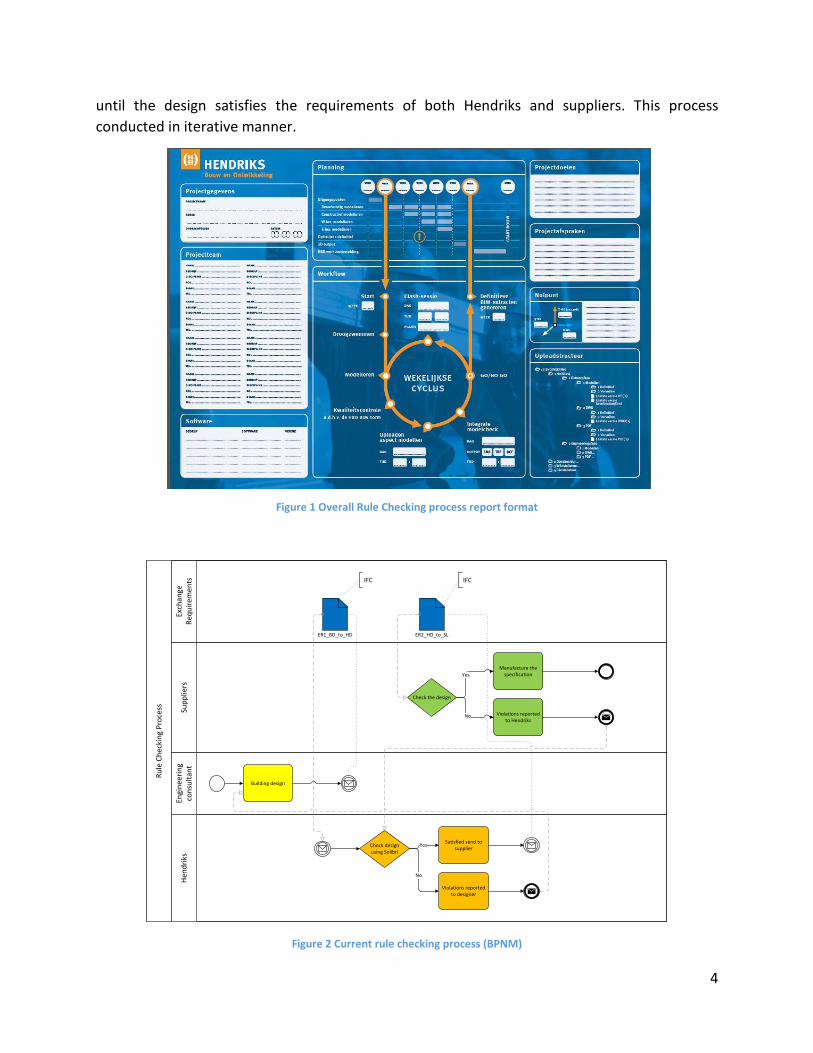
Currently Hendriks is using the Solibri Model Checker (SMC) to check and validate the BIM
models. The process of rule checking is conducted on a weekly basis and is documented. The
rule check document contains the details about the project, team members, software user to
draft the model and most importantly the clashes and violations arise during the process of rule
checking. These clashes and violations were illustrated using the screen shot presentation from
the Solibri Model Checker and it is attached to that document. The main objective of this
documentation is to highlight the type of violations or errors in the design and send to the
respective person for decision making. This process of rule checking is conducted in iterative
manner until it satisfies the specifications. The conclusion was drawn that the go/no-go
moments in a project. The below figure 1 shows the overall contain of the document.
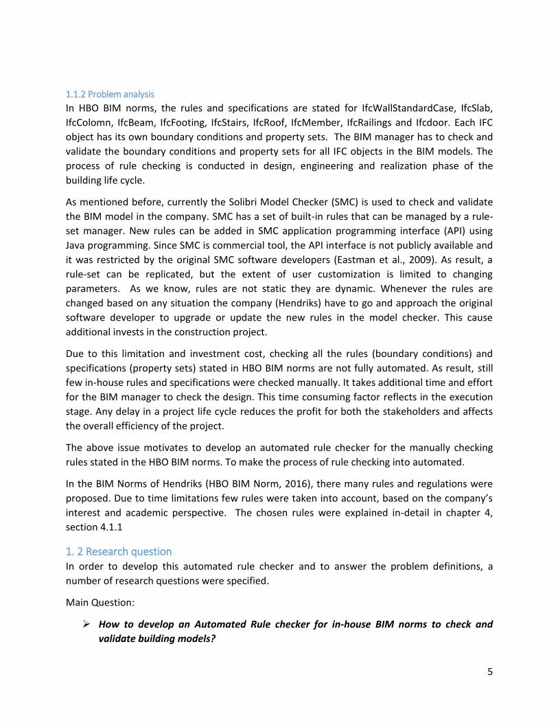
To be clearer, a BPNM models is illustrated in figure 2 to show the current the rule checking
process in the company. Initially, the building design is designed by the Engineering consultant
(designer). The design is send to the client (Hendriks) in an IFC file format. Using Solibri Model
Checker (SMC), the design will be checked and validated. If there are any violations or clashes
arise during the process of rule checking, a detail report is send to the designer to solve those
issues. If the design is satisfied, it will be send to the supplier. The design is double checked by
the supplier. During this process if the design is perfect, the specifications (products) were send
for production. Suppose, if there is any violation or issue in the design a detail report is send to
Hendriks by the supplier. Based on those issues, the rule checking process is conducted again
4
until the design satisfies the requirements of both Hendriks and suppliers. This process
conducted in iterative manner.
Figure 1 Overall Rule Checking process report format
Ru
le C
hec
kin
g P
roce
ss
Exch
ange
R
equ
irem
ents
En
gin
eeri
ng
con
sult
ant
Hen
dri
ks
Sup
plie
rs
Building design
ER1_BD_to_HD
Check design using Solibri
Satisfied send to supplier
Yes
Violations reported to designer
No
ER2_HD_to_SL
Check the design
Manufacture the specificationYes
Violations reported to Hendriks
No
IFC IFC
Figure 2 Current rule checking process (BPNM)
5
1.1.2 Problem analysis
In HBO BIM norms, the rules and specifications are stated for IfcWallStandardCase, IfcSlab,
IfcColomn, IfcBeam, IfcFooting, IfcStairs, IfcRoof, IfcMember, IfcRailings and Ifcdoor. Each IFC
object has its own boundary conditions and property sets. The BIM manager has to check and
validate the boundary conditions and property sets for all IFC objects in the BIM models. The
process of rule checking is conducted in design, engineering and realization phase of the
building life cycle.
As mentioned before, currently the Solibri Model Checker (SMC) is used to check and validate
the BIM model in the company. SMC has a set of built-in rules that can be managed by a rule-
set manager. New rules can be added in SMC application programming interface (API) using
Java programming. Since SMC is commercial tool, the API interface is not publicly available and
it was restricted by the original SMC software developers (Eastman et al., 2009). As result, a
rule-set can be replicated, but the extent of user customization is limited to changing
parameters. As we know, rules are not static they are dynamic. Whenever the rules are
changed based on any situation the company (Hendriks) have to go and approach the original
software developer to upgrade or update the new rules in the model checker. This cause
additional invests in the construction project.
Due to this limitation and investment cost, checking all the rules (boundary conditions) and
specifications (property sets) stated in HBO BIM norms are not fully automated. As result, still
few in-house rules and specifications were checked manually. It takes additional time and effort
for the BIM manager to check the design. This time consuming factor reflects in the execution
stage. Any delay in a project life cycle reduces the profit for both the stakeholders and affects
the overall efficiency of the project.
The above issue motivates to develop an automated rule checker for the manually checking
rules stated in the HBO BIM norms. To make the process of rule checking into automated.
In the BIM Norms of Hendriks (HBO BIM Norm, 2016), there many rules and regulations were
proposed. Due to time limitations few rules were taken into account, based on the company’s
interest and academic perspective. The chosen rules were explained in-detail in chapter 4,
section 4.1.1
1. 2 Research question In order to develop this automated rule checker and to answer the problem definitions, a
number of research questions were specified.
Main Question:
How to develop an Automated Rule checker for in-house BIM norms to check and
validate building models?
6
Sub-Question
What are the rules chosen for this rule checking process and why it is stated in the in-
house BIM norms?
What data is needed to conduct this automated rule checking process?
How is this automated rule checker beneficial for the BIM manager for decision
making?
To get the answers for the above research questions a methodology is formulated. This
methodology and conceptual frame work is illustrated and brief in the below chapter 4.
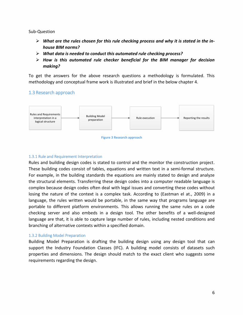
1.3 Research approach
Rules and Requirements interpretation in a logical structure
Building Model preparation
Rule execution Reporting the results
Figure 3 Research approach
1.3.1 Rule and Requirement Interpretation
Rules and building design codes is stated to control and the monitor the construction project.
These building codes consist of tables, equations and written text in a semi-formal structure.
For example, in the building standards the equations are mainly stated to design and analyze
the structural elements. Transferring these design codes into a computer readable language is
complex because design codes often deal with legal issues and converting these codes without
losing the nature of the context is a complex task. According to (Eastman el at., 2009) in a
language, the rules written would be portable, in the same way that programs language are
portable to different platform environments. This allows running the same rules on a code
checking server and also embeds in a design tool. The other benefits of a well-designed
language are that, it is able to capture large number of rules, including nested conditions and
branching of alternative contexts within a specified domain.
1.3.2 Building Model Preparation
Building Model Preparation is drafting the building design using any design tool that can
support the Industry Foundation Classes (IFC). A building model consists of datasets such
properties and dimensions. The design should match to the exact client who suggests some
requirements regarding the design.
7
1.3.3 Rule Execution
Rule checking is straightforward when rules and requirements were converted into a machine
readable format. The functions must deal with the prepared building model. The rules are
executed by applying the set of rules to the instance building model.
1.3.4 Reporting the Result
The main objective of reporting is to communicate the end result of the rule checking process
to the respective stakeholders involved in the project. This reporting process, use for decision
making and solving problems raised during the project life cycle.
1.4 Expected results The main objective of this graduation project is to develop an automated rule checker for the
in-house BIM norm. This rule checker helps to find the mismatches and violations in the design
against the in-house rules. Once this rule checker is fully developed the end user (BIM manager)
can check multiple model instances. In addition to that, this project concerns about
representing the mismatch and violation in a 3D view. This helps the BIM manager to
communicate the end result with the designers and supplier chain partners involved in the
project. Overall, this automated rule checking process reduces the time used in the rule
checking process. Visualizing the violations and mismatches (if any) in a 3D view, helps for
effective communication among the stakeholders in the project. To achieve this objective, a
methodology is formulated. By implementing that formulated method an automated rule
checker for in-house BIM norm can be developed.

8
9
Chapter-2
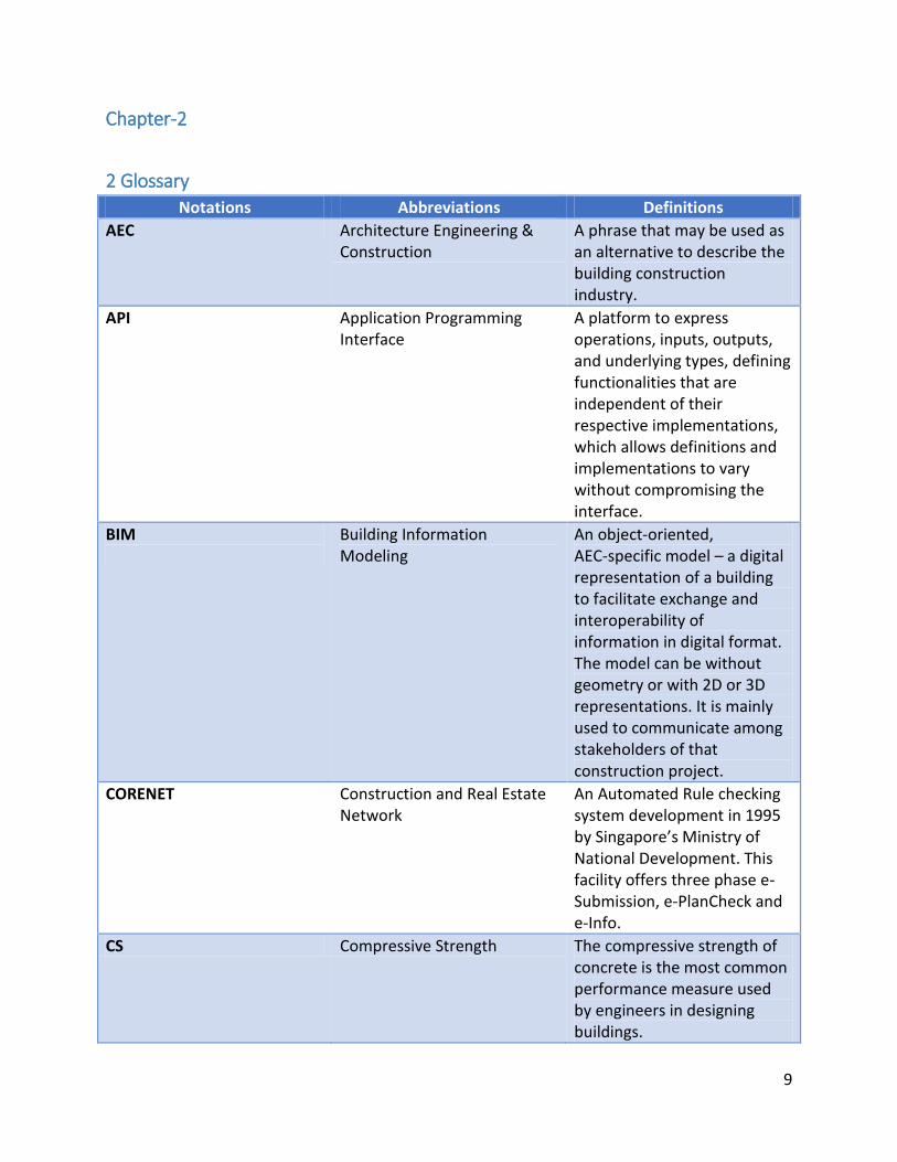
2 Glossary Notations Abbreviations Definitions
AEC Architecture Engineering & Construction
A phrase that may be used as an alternative to describe the building construction industry.
API Application Programming Interface
A platform to express operations, inputs, outputs, and underlying types, defining functionalities that are independent of their respective implementations, which allows definitions and implementations to vary without compromising the interface.
BIM
Building Information Modeling
An object‐oriented, AEC‐specific model – a digital representation of a building to facilitate exchange and interoperability of information in digital format. The model can be without geometry or with 2D or 3D representations. It is mainly used to communicate among stakeholders of that construction project.
CORENET Construction and Real Estate Network
An Automated Rule checking system development in 1995 by Singapore’s Ministry of National Development. This facility offers three phase e-Submission, e-PlanCheck and e-Info.
CS Compressive Strength The compressive strength of concrete is the most common performance measure used by engineers in designing buildings.
10
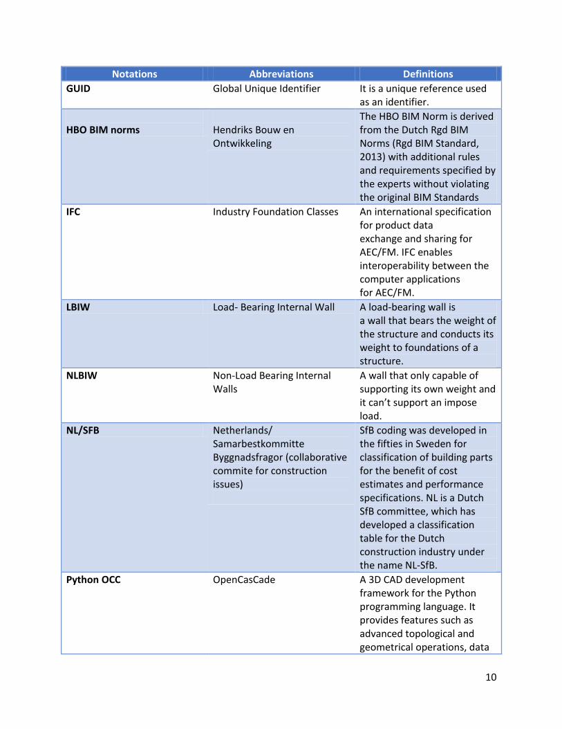
Notations Abbreviations Definitions
GUID Global Unique Identifier It is a unique reference used as an identifier.
HBO BIM norms
Hendriks Bouw en Ontwikkeling
The HBO BIM Norm is derived from the Dutch Rgd BIM Norms (Rgd BIM Standard, 2013) with additional rules and requirements specified by the experts without violating the original BIM Standards
IFC Industry Foundation Classes An international specification for product data exchange and sharing for AEC/FM. IFC enables interoperability between the computer applications for AEC/FM.
LBIW Load- Bearing Internal Wall A load-bearing wall is a wall that bears the weight of the structure and conducts its weight to foundations of a structure.
NLBIW Non-Load Bearing Internal Walls
A wall that only capable of supporting its own weight and it can’t support an impose load.
NL/SFB Netherlands/ Samarbestkommitte Byggnadsfragor (collaborative commite for construction issues)
SfB coding was developed in the fifties in Sweden for classification of building parts for the benefit of cost estimates and performance specifications. NL is a Dutch SfB committee, which has developed a classification table for the Dutch construction industry under the name NL-SfB.
Python OCC OpenCasCade A 3D CAD development framework for the Python programming language. It provides features such as advanced topological and geometrical operations, data
11
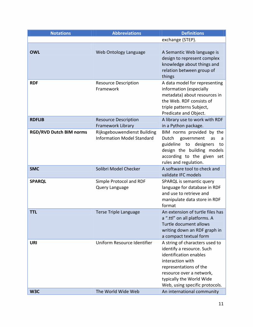
Notations Abbreviations Definitions
exchange (STEP).
OWL
Web Ontology Language
A Semantic Web language is design to represent complex knowledge about things and relation between group of things
RDF Resource Description Framework
A data model for representing information (especially metadata) about resources in the Web. RDF consists of triple patterns Subject, Predicate and Object.
RDFLIB Resource Description Framework Library
A library use to work with RDF in a Python package.
RGD/RVD Dutch BIM norms Rijksgebouwendienst Building Information Model Standard
BIM norms provided by the Dutch government as a guideline to designers to design the building models according to the given set rules and regulation.
SMC Solibri Model Checker A software tool to check and validate IFC models
SPARQL Simple Protocol and RDF Query Language
SPARQL is semantic query language for database in RDF and use to retrieve and manipulate data store in RDF format
TTL Terse Triple Language An extension of turtle files has a “.ttl” on all platforms. A Turtle document allows writing down an RDF graph in a compact textual form
URI Uniform Resource Identifier A string of characters used to identify a resource. Such identification enables interaction with representations of the resource over a network, typically the World Wide Web, using specific protocols.
W3C The World Wide Web An international community
12
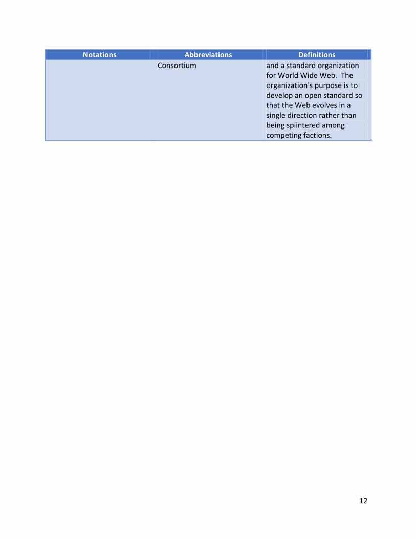
Notations Abbreviations Definitions
Consortium and a standard organization for World Wide Web. The organization's purpose is to develop an open standard so that the Web evolves in a single direction rather than being splintered among competing factions.
13
Chapter-3
3 Literature Review In recent years the AEC industry became more complex due to larger number of stakeholders
involved in the same construction project. This increase in the number of stakeholders effects
the effective collaboration. According to (Charalambous, Thorpe, Yeomans, & Doughty, 2013)
“Effective collaboration requires coordinated communication and communicated
coordination”. Building Information Modeling (BIM) can be expressed as the language to
coordinate the communication in the construction industry. Collaboration not only means
exchange of data among the stakeholders but also checking and validating of those exchanged
data. To check and validate the data there are few automated rule checkers such as the Solibri
Model Checker (SMC) and Revit tools are available in the market. These tools are sometimes
isolated or differ from the current requirement. A strong coordination between these
requirement and tools is beneficial for a better collaboration. Semantic web technologies and
Linked Data approach can be helpful to achieve this aim (Costa & Pauwels, 2015).
In this chapter, current studies between BIM and Linked Data approach are discussed, in order
to show the development of BIM and Linked Data approach in the construction industry. Based
on these development, an automated rule checker is beneficial in rule checking is conducted in
the end.
3.1 Building Information Modeling (BIM) and Industry Foundation Classes (IFC)
Building Information Modeling (BIM) is an emerging technology in the AEC industry. BIM
technology helps to present the building design in three dimensional views and it is also known
as virtual building. This virtual building plays a major role in the process of simulations, testing,
refining and validation of building design (Christiansson et al., 2010). BIM technology not only
beneficial in virtual buildings and rule checking, it also gives an opportunities for the
stakeholders to control the important variables of the project such as cost and time
management (Azhar et al., 2008).
The Industry Foundation Classes (IFC) is a standard data model that supports the data exchange
via BIM. Its schema is developed in the EXPRESS modelling language (Beetz et al., 2014). There
are many modelling language available to describe the product and their data, but the EXPRESS
is the most successful modelling language define in ISO 10303-11:19994 was adopt. The
EXPRESS language consist of the elements that allows an unambiguous data definition and is
part of the Standard for the Exchange of Product data (STEP) standard to define how the
product data should be describe and exchanged (Pauwels, et al., 2010).
There are lot of research and development effort ongoing in the field of Building Information,
Modelling (BIM), and every research has its own limitations. There are some limitations in the
14
field of BIM. Since BIM is more technically advanced it is difficult for the non-professional client
to understand and particularly elderly people are resisting to accept this technology even
though it has benefits (Vries et al., 2012). According to a survey conducted by (Yan & Damian,
2008) over 40% of the USA and 20% UK construction companies are not interested to adopt
BIM because they have to invest time and human recourse to train their employees in Building
Information Modelling field. The percentage of adopting this technology is increasing day by
day.
Although, the Industry Foundation Classes (IFC) is a central and standardized data model shared
among the different stakeholders in a project it has some limitations. The IFC file format is not
based on a mathematically rigid theory like OWL and lacks formal rigidness. The EXPRESS
modelling language has limitations in resources reuse and interoperability. Few developers
have knowledge on this modeling language so it reduces the development of affordable and
free tools (Beetz et al., 2009) .The details of domain information are not explicitly available in
the modelled data (Beetz et al., 2015). Information picking i.e. the stakeholder can’t pick
specific information from the IFC model they must receive the full size model (Fischer & Kam,
2002).
3.2 Linked Data and Semantic web
The name Linked Data itself defines its definition, linking of data from different sources.
Technically, Linked Data define as the data published on the World Wide Web in a machine-
readable format and its meaning is explicitly defined. Then it is linked to other external data
sets, and can be linked from external data sets (Christian et al., 2008). The principle of Linked
Data is first outlined by Tim Berners-Lee in 2006 (Berners-Lee et al., 2008). The Semantic Web
shares the data and reuse among companies and community boundaries (Campbell & MacNeill,
2010). The Semantic not only requires machine-readable language, but also in the machine
understandable format. The machine-readable format recommended by World Wide
Consortium (W3C) is Resource Description Framework (RDF) in February 1999 (W3C, 2014)3.
The concept of Resource Description Framework (RDF) is a data model for representing
information (especially metadata) about resources on the Web. Metadata gives the information
about other data. RDF data model makes a statement about the resource in the form of
subject,predicate,object expressions. These expressions are known as “triples” in RDF
terminology.To identify the resources, RDF uses Uniform Resource Identifiers (URIs) and URI
references (URIRefs) (Decker et al., 2000). The Triple patterns are identified by the following
format:
- Subjects can be either URIs or Blank nodes
- Predicates are mostly URI
- Objects can be URIs, Blank nodes or literals.
3 https://www.w3.org/TR/rdf-schema/
15
These triple patterns from different data can be linked together and form as RDF graphs
(Hitzler, 2011)
The exact meaning of an RDF graph in a general context depends on many factors, which
include conventions within a user community to interpret user-defined RDF classes and
properties in specific ways, comments in natural language, or links to other content bearing
documents. But the meaning is much more convey that these forms will not directly accessed
by the machine processing. This meaning may be used by human interpreters of the RDF
information, or by programmers writing software to perform various kinds of processing on
that RDF information. However, RDF statements also have a formal meaning which determines,
with mathematical precision, the conclusions (or entailments) that machines can draw from a
given RDF graph (W3C, 2004)4. To retrieve and manipulate data store in RDF format or graph
using Simple Protocol and RDF Query Language and it’s shortly known as SPARQL (Prudhomme
& Seabome, 2008). SPARQL is a semantic query language for database in RDF and it recommend
by World Wide Consortium (W3C) in 1998 (W3C, 2013)5.
SPARQL is a graph matching query language and a query consist of three parts. They are as
follows:
- Pattern match
- Solution modifiers
- Output
Pattern match consist of several operation to find the matching pattern in RDF graph such as
optional parts, union of patterns, nesting, filtering (or restricting) values of possible matching’s,
and the possibility of choosing the data source to be matched by a pattern. Solution modifiers
use to modify the computed output values using projection, distinct, order, limit, and offset.
Output, based on the query the end result (output) differs, such as matching of patterns,
construction of new triples from these values, and descriptions of resources (Perez et al., 2006).
Since the Semantic Web technology getting popular, the need for this technology in many
applications to support the rule based inference engine for processing Semantic Web data in an
intelligent manner. Many rule languages are proposed to allow rule reuse and interoperations
(Ameen et al., 2015). Some the rule languages for Semantic Web are RuleML, Semantic Web
Rule Language (SWRL), Notation3 (N3), Jane rules and Rule Interchange Format (RIF) (Paschke &
Boley, 2009).
3.3 BIM, Linked Data and Semantic web
In the context of Semantic Web technology, ontology are playing a vital role for publishing and
connecting structured data on the web as Linked data. In the AEC industry Building Information
Modelling (BIM) is being used as central place of building data to facilitate exchange of data in
4 https://www.w3.org/TR/rdf-primer/
5 https://www.w3.org/TR/sparql11-query/
16
digital format by all stakeholders across the project life cycle. In order to make a bride between
the BIM, Semantic Web and Linked data (Lee et al., 2016) suggest framework to achieve the
above mentioned goal. They are as follows:
- Develop an ontology for publishing data in a linked data principles
- Extract the information from the BIM model and generate or convert into a machine-
readable format
- Convert the extracted BIM data into a RDF graph
- Use SPARQL query to retrieve or modified the output data.
To create a link between different building data, can be achieved by create vocabularies using
Linked data approach. A Vocabulary is a set of classes and properties used to describe specific
types of things, or things in a given domain or industry, but for a specific usage. Vocabularies
are used RDF, RDF Schema (W3C, 2004)6and Web Ontology Language (OWL, 2012)7 that defines
the main schema modeling constructs such as “owl:Class” or “rdf:Propetry”.
In Building data, such as a BIM, in a Linked data format, can be combined with other relevant
data sets. By doing so, the AEC industry can generate and extract additional valuable
information across different domains in the industry. As result, cross domain information gives
a clear view of buildings operations and also provides added value for the domain stakeholders
in the organization. This valuable information is used take decision support throughout the
project life cycle (Curry et al., 2012).
3.4 Rules and Regulation
Rules and Regulation are written by experts (humans) in that field in a natural language. These
rules and regulations are composed into a set of standards are known as building standards.
These building standards differ from country to country based on local conditions and these
rules are often published by the public legal bodies in both national and international level
(Hjelseth & Nisbet, 2011). These building standards are mostly in the form of documents,
forms, orders and information data base.
The European Union suggests a series of 10 European Standards and providing a common
approach for the design of buildings and other civil engineering works and construction
products ( EN Eurocodes, 2013)8 . In particular, Netherlands follows the European standards,
with additional rules and regulations were published as local building standards in Building
Decree 2012 (Bouwbesluit 2012). This decree contains the technical regulations for all type
structures in the Netherlands. These Dutch regulations are more concerned about the safety,
health, usability, energy efficiency and green environment. Note that the Building rules can
6 https://www.w3.org/TR/rdf-primer/
7 https://www.w3.org/2001/sw/wiki/OWL
8 http://eurocodes.jrc.ec.europa.eu/
17
differ from one municipality to another (Building regulations, 2012)9. In particular, the
Netherlands proposed a BIM standard know as the Rijksgebouwendienst Building Information
Model Standard, shortly referred to as RGD Dutch BIM norms (Rillaer et al., 2012). This Rdg BIM
norms provides guidelines to designers to design the building models according to the given set
rules and regulations.
Even though these building standards are published to regulate the building design, due to the
large number of the rules standards, checking and validate these rules manually is a complex
task. This complexity reduces the efficiency of the project life cycle.
3.5 Automated Rule Checking and Linked Data
Rules and Regulation plays a vital role in the AEC industry by controlling and monitoring a
construction project. These Rules and Regulations are written in natural language, converting
these rules and regulations without changing the gist into machine-readable codes to check the
design is part of the Automated Rule checking process. This automated process helps to
increase the efficiency of the project and allows rapid decision-making in that particular issue
(Park & Kim, 2015).To achieve this rule checking process (C. Eastman et al., 2009) suggest four
different phases. They are:
- Rule and Requirement interpretation in a logical structure;
- Building model preparation;
- Rule execution;
- Reporting the results.
An Automated rule checker is a software tool which doesn’t make any change or alternation in
the original design but is can accesses the design to check and validate the object and attributes
in that design (C. Eastman et al., 2009). Eastman state that “Rule-based systems applies rules,
constraints or conditions to a proposed design, with results such as “pass”, “fail” or “warning”,
or ‘unknown’ for cases where the needed data is incomplete or missing”.
Automated Rule checking is not new concept. In 1995 Singapore’s Ministry of National
Development initiated the effort of automated code checking. The objective of “CORENET is to
re-engineer the business processes of the construction industry to achieve a quantum leap in
turnaround time, productivity and quality” .CORENET is standards for Construction and Real
Estate Network. This facility offers three phases of services namely: e-Submission, e-Plan-Check
and e-Info (Government of Singapore, 2016)10. CORENET is developed novaCITYNETS Pte. Ltd in
the own platform called FORNAX. By using FORNAX objects, a rule written in natural language
could be directly interpreted to programming language. FORNAX has a C++ object library to
obtain new data and generate extended views of IFC data. The results of this e-checking is
9 http://www.answersforbusiness.nl/regulation/building-regulations
10 https://www.corenet.gov.sg
18
delivered in the form of word or pdf and also in the graphical format (Eastman et al., 2009).
Since the FORNAX library which has been developed and maintained by a private company,
expanding and hard-coded checking routines are not transparent for the public. The rule
checking codes are highly confidential. Therefore it is called a black box method (Preidel et al.,
2015).
Solibri Model Checker (SMC) is a Java based model checker developed in the year 2000 by the
Finnish software development company known as Solibri Inc. SMC can read the IFC files and
check the models with its preset rule libraries. By using the rule libraries available in the SMC,
the user can check and validate the model based on the chosen rules from the rule library.
Since Solibri is a commercial tool, external development of new or custom rule sets is only
possible with a cooperation of the original SMC software developer (Preidel & Borrmann,
2015).
Jotne EDModelChecker is another model checker, based on the EXPRESS language. This
platform providing an object database and supports the open development of new rules in
EXPRESS language. The IFC schema is also written in EXPRESS language .Working knowledge of
the rule written EXPRESS is limited within a small group of people (Eastman, et al., 2009).
SMART-Code is developed by International Code Council (ICC). It formalized process of rule by
converting the rules written in natural language into computer readable format (codes)
(Nawari, 2012). Unfortunately due lack of funding the development of SMART-Code is stopped
in 2010. The underlying mark-up concept used by SMART-Codes has been developed further by
AEC3 Ltd (Hjelseth, 2012).
The above mentioned (FORNAX, SMC, EDM & SMART-Code) state of the art technologies still
have limitations in terms of interoperability (Tan et al., 2010). Moreover these technologies are
not transparent and such that any editing, modifications of existing rules, or addition of new
rules have to be done by editing the original code by a person with a sound knowledge in the
field of computer science. The state art of tools lacks the capability of performing logical
compliance checking. Such as contractual requirement, quality control and safety procedures
are not semantically represented in the BIM model (Kasim, Li, Rezgui, & Beach, 2013).
When it comes to Linked data, several authors like ( Beetz et al 2009,Pauwels, et al., 2010) have
done lot of research and development over a decade to make a bridge between BIM and Linked
data, based on Semantic Web techonolgy. Espically, in the process of rule checking linked data
has the potential to play a vital role. Data from different domains described in RDF format can
be linked through semantic rules and the information from the BIM models descibres in this
format .This cross domain information gives an opportunity to link alternative representations
of building information to show potential interrelationship among diverse sources of
information in a building project. The main advantage of linked data and semantic web
technology is that the schema, instances, and the rules can be defined in a common frame with
the same language (Pauwels et al., 2015).
19
3.6 Conculsion Even though an automated rule checker has lot of benefits, converting every rules and
regulations from natural language without changing its natural context into machine-readable
format is a complex task. From the above analysis, the IFC data model contains the whole
information about the project and converting these STEP-based instance models into a RDF file
can be achieved. Using Linked Data approach allows models information from different data
source to be linked together. By using the SPARQL query language we can retrieve or modify
the data. By adopting the above author’s suggestions and guidelines a prototype of an
automated rule checker can be developed.

20
21
Chapter-4
4 Methodology In this chapter the methodology to develop an automated rule checker is explained with work
flow diagrams. Initially, the conceptual frame is illustrated, the rules and requirements chosen
to develop an automated rule checker are explained and the computer programming and query
language is briefed. Finally, the conceptual work flow is explained.
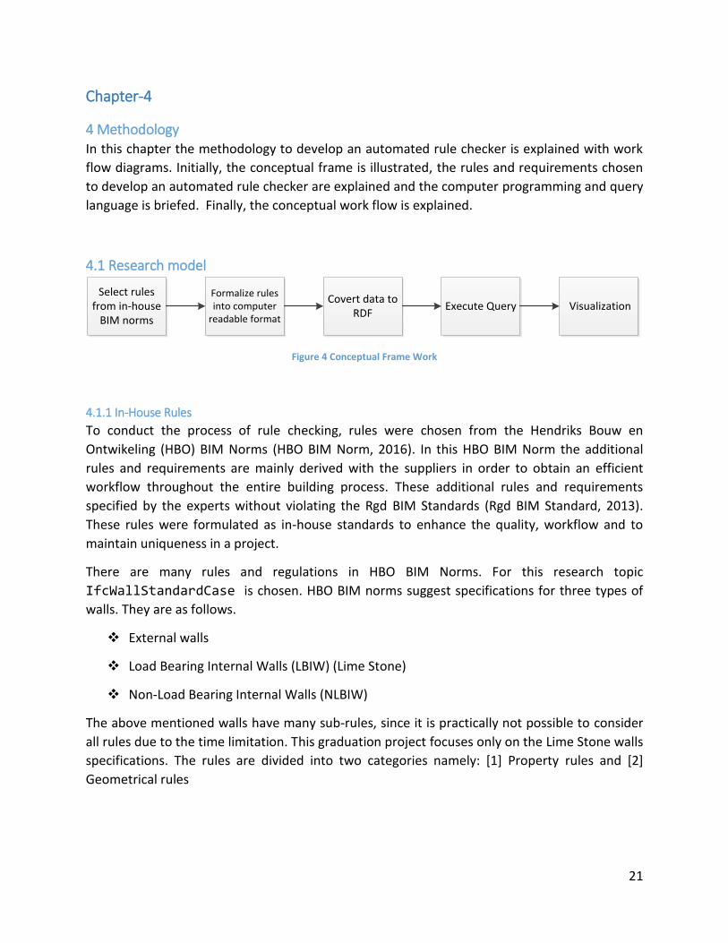
4.1 Research model
Covert data to RDF
Select rules from in-house
BIM norms
Formalize rules into computer
readable format Execute Query Visualization
Figure 4 Conceptual Frame Work
4.1.1 In-House Rules
To conduct the process of rule checking, rules were chosen from the Hendriks Bouw en
Ontwikeling (HBO) BIM Norms (HBO BIM Norm, 2016). In this HBO BIM Norm the additional
rules and requirements are mainly derived with the suppliers in order to obtain an efficient
workflow throughout the entire building process. These additional rules and requirements
specified by the experts without violating the Rgd BIM Standards (Rgd BIM Standard, 2013).
These rules were formulated as in-house standards to enhance the quality, workflow and to
maintain uniqueness in a project.
There are many rules and regulations in HBO BIM Norms. For this research topic
IfcWallStandardCase is chosen. HBO BIM norms suggest specifications for three types of
walls. They are as follows.
External walls
Load Bearing Internal Walls (LBIW) (Lime Stone)
Non-Load Bearing Internal Walls (NLBIW)
The above mentioned walls have many sub-rules, since it is practically not possible to consider
all rules due to the time limitation. This graduation project focuses only on the Lime Stone walls
specifications. The rules are divided into two categories namely: [1] Property rules and [2]
Geometrical rules
22
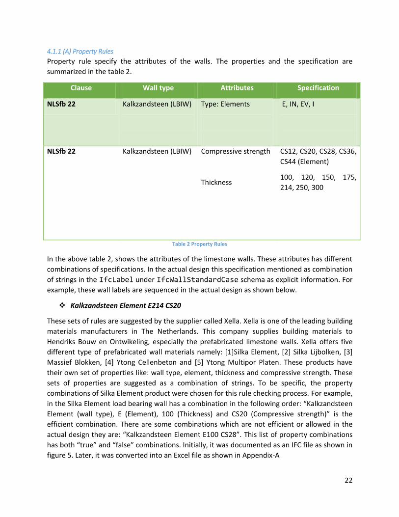
4.1.1 (A) Property Rules
Property rule specify the attributes of the walls. The properties and the specification are
summarized in the table 2.
Clause Wall type Attributes Specification
NLSfb 22 Kalkzandsteen (LBIW)
Type: Elements
E, IN, EV, I
NLSfb 22 Kalkzandsteen (LBIW) Compressive strength
Thickness
CS12, CS20, CS28, CS36,
CS44 (Element)
100, 120, 150, 175,
214, 250, 300
Table 2 Property Rules
In the above table 2, shows the attributes of the limestone walls. These attributes has different
combinations of specifications. In the actual design this specification mentioned as combination
of strings in the IfcLabel under IfcWallStandardCase schema as explicit information. For
example, these wall labels are sequenced in the actual design as shown below.
Kalkzandsteen Element E214 CS20
These sets of rules are suggested by the supplier called Xella. Xella is one of the leading building
materials manufacturers in The Netherlands. This company supplies building materials to
Hendriks Bouw en Ontwikeling, especially the prefabricated limestone walls. Xella offers five
different type of prefabricated wall materials namely: [1]Silka Element, [2] Silka Lijbolken, [3]
Massief Blokken, [4] Ytong Cellenbeton and [5] Ytong Multipor Platen. These products have
their own set of properties like: wall type, element, thickness and compressive strength. These
sets of properties are suggested as a combination of strings. To be specific, the property
combinations of Silka Element product were chosen for this rule checking process. For example,
in the Silka Element load bearing wall has a combination in the following order: “Kalkzandsteen
Element (wall type), E (Element), 100 (Thickness) and CS20 (Compressive strength)” is the
efficient combination. There are some combinations which are not efficient or allowed in the
actual design they are: “Kalkzandsteen Element E100 CS28”. This list of property combinations
has both “true” and “false” combinations. Initially, it was documented as an IFC file as shown in
figure 5. Later, it was converted into an Excel file as shown in Appendix-A
23
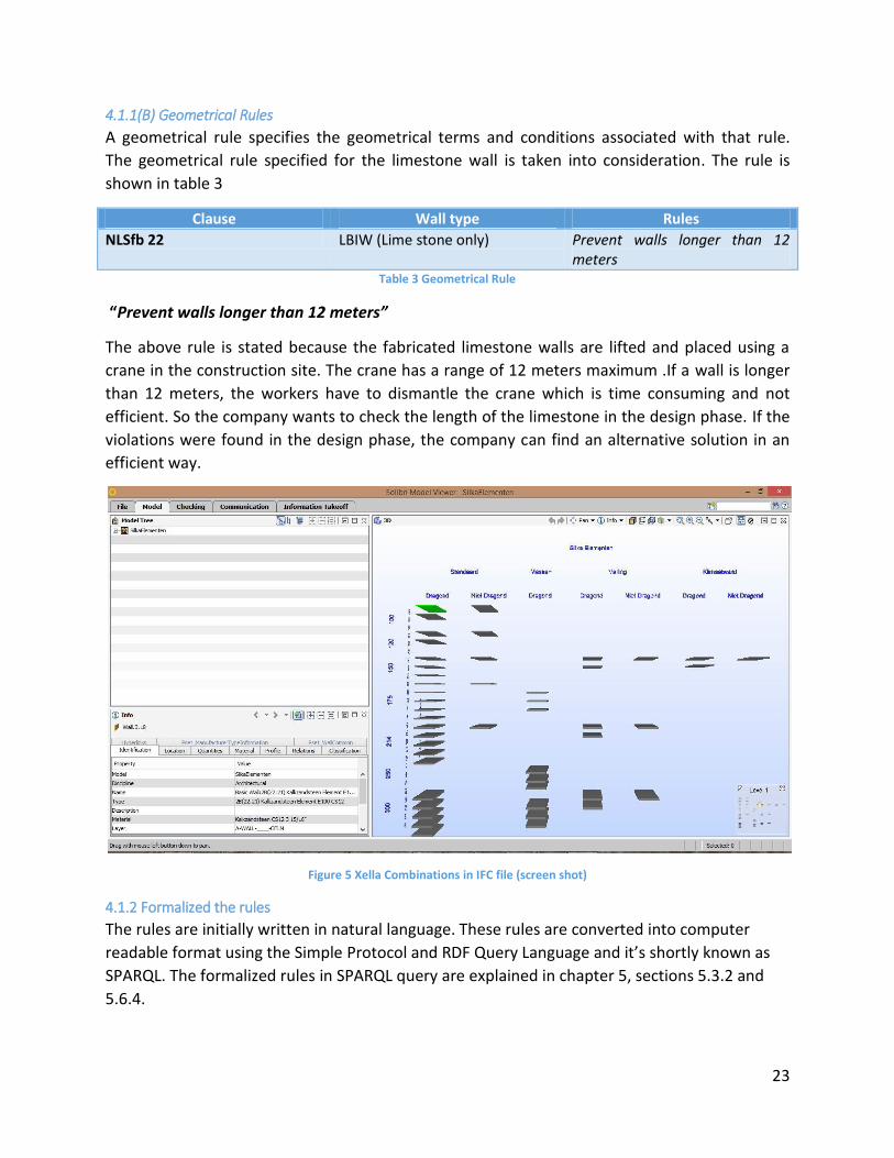
4.1.1(B) Geometrical Rules
A geometrical rule specifies the geometrical terms and conditions associated with that rule.
The geometrical rule specified for the limestone wall is taken into consideration. The rule is
shown in table 3
Clause Wall type Rules
NLSfb 22 LBIW (Lime stone only) Prevent walls longer than 12 meters
Table 3 Geometrical Rule
“Prevent walls longer than 12 meters”
The above rule is stated because the fabricated limestone walls are lifted and placed using a
crane in the construction site. The crane has a range of 12 meters maximum .If a wall is longer
than 12 meters, the workers have to dismantle the crane which is time consuming and not
efficient. So the company wants to check the length of the limestone in the design phase. If the
violations were found in the design phase, the company can find an alternative solution in an
efficient way.
Figure 5 Xella Combinations in IFC file (screen shot)
4.1.2 Formalized the rules
The rules are initially written in natural language. These rules are converted into computer
readable format using the Simple Protocol and RDF Query Language and it’s shortly known as
SPARQL. The formalized rules in SPARQL query are explained in chapter 5, sections 5.3.2 and
5.6.4.
24
4.1.3 Convert data to RDF
The data such IFC model and the supplier combination in Excel file is converted to an RDF file
format. The main purpose of converting data to RDF is to maintain the uniform data format
throughout the rule checking process. Initially, the IFC model which is STEP file format will be
converted into an IfcOWL format. IfcOWL (Beetz et al.., 2009) is an ontology that can be
published to synchronized with IFC specification IfcOWL is use to allow extension towards
structured data sets and link the data to made it present online using semantic web technology
(buildingSMART, 2016). The supplier combination Excel file is converted into RDF file. The
process of converting the data into RDF file is explained in chapter 5.
4.1.4 Execution and Visualization
As mentioned before, the rules are formalized using SPARQL query language. By executing the
rules (query) against the IFC model gives an opportunity to check and validate the design. The
result of this process of rule checking can visualize in the form of text, graphs, tables and 3D
graphical view. In this case, the end result of this automated rule checker is visualized in a three
dimensional view. To achieve this Python programming language along with its libraries and
modules are adopted.
Python is an object oriented high level computer programming language with dynamic
semantics. Python has advantages for use in back end application. For instance, the code is
highly readable and the syntax is easy to learn, enabling users without extensive programming
experience to work with the framework. Moreover, Python can be extended by importing
additional libraries, such rdflib, IfcOpenShell and PythonOCC. IfcOpenShell is an open source
software library that helps users to work with the IFC file format. In other words IfcOpenShell is
basically used to edit or add new codes to .ifc file. This helps to import and export information
from IFC files (Krijnen, 2015)11.
4.2 Conceptual Frame work
The above conceptual work flow diagram (figure 3) shows the process to develop this
automated rule checker. Initially, the rules and requirements mentioned in section 4.1.1 are
written in natural language were collected from Hendriks Bouw en Ontwikeling. These rules
were formalized into computer readable format using SPARQL. The role of python program
language is more in the geometrical rule checking process. The geometrical representations in
an IFC schema are not explicit, so python programming language is used to calculate the
dimensions of the walls. The IFC model and supplier’s specifications in Excel files are converted
into an RDF files. The SPARQL query is executed to check the design. Finally, the violated walls
were visualized in a three dimensional view using Python libraries. Implementation of this
process in explained in chapter 5.
11
http://ifcopenshell.org/index.html
25
Chapter-5
5 Implementation In this Chapter, the implementation procedure to develop a prototype Automated Rule checker
is explained. Initially, a brief introduction is given about the programming & querying language
and also Integrated Development Environment (IDE) used in this process. As mentioned before,
the process of rule checking is divided into two categories namely: [1] Property Rule Checking
and, [2] Geometric Rule checking. Each rule checking process has followed different
implementation procedure to achieve the end results to find the mismatch and violations based
on the in-house rules in a BIM model. Both implementations are illustrated using work flow
diagrams. A step by step procedure of the programming part is explained using separate work
flow diagrams. The output of this automated rule checker illustrated using screen shots .Finally,
a discussion is made based the assumptions, limitations in this process and few
recommendations were given for future development.
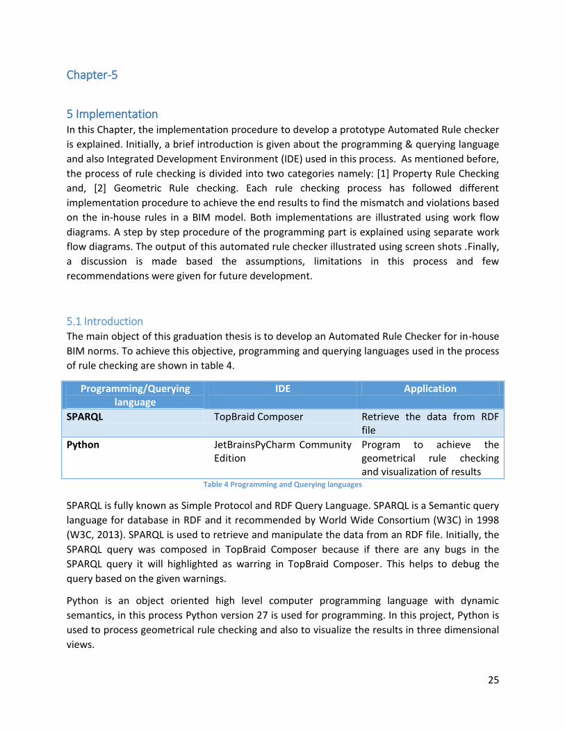
5.1 Introduction The main object of this graduation thesis is to develop an Automated Rule Checker for in-house
BIM norms. To achieve this objective, programming and querying languages used in the process
of rule checking are shown in table 4.
Programming/Querying language
IDE Application
SPARQL TopBraid Composer Retrieve the data from RDF file
Python JetBrainsPyCharm Community Edition
Program to achieve the geometrical rule checking and visualization of results
Table 4 Programming and Querying languages
SPARQL is fully known as Simple Protocol and RDF Query Language. SPARQL is a Semantic query
language for database in RDF and it recommended by World Wide Consortium (W3C) in 1998
(W3C, 2013). SPARQL is used to retrieve and manipulate the data from an RDF file. Initially, the
SPARQL query was composed in TopBraid Composer because if there are any bugs in the
SPARQL query it will highlighted as warring in TopBraid Composer. This helps to debug the
query based on the given warnings.
Python is an object oriented high level computer programming language with dynamic
semantics, in this process Python version 27 is used for programming. In this project, Python is
used to process geometrical rule checking and also to visualize the results in three dimensional
views.
26
Resource Description Framework (RDF) plays a vital role in this project. The IFC model in which
the company is interested to check the properties of the walls was converted using the IFC to
RDF converter. This, IFC-to-RDF converter is a configurable Java program with open API
(Pauwels et al., 2012). The IFC model which is in STEP file format is import to the converter
(Java, API) and exported as an RDF file format. The process of converting IFC to RDF creates an
opportunity to link alternative representations of building information to show potential
interrelationship among diverse sources of information in a building project.
The combinations of wall properties are suggested by the supplier in section 4.1.1 are listed in
an Excel file. Using Google Open Refine this Excel file is converted into an RDF file (Open Refine
, 2012). During this process of converting Excel to RDF, the Excel file is imported into Google
Open Refine. The base or instance URI and reference URI are created. The reference URI
(predicate) is associated with wall attributes (objects) as strings. Finally, the file was exported
in an RDF file format. By using these above mentioned programming and querying languages,
implementations process to develop a prototype automated rule checker is explained in this
chapter.
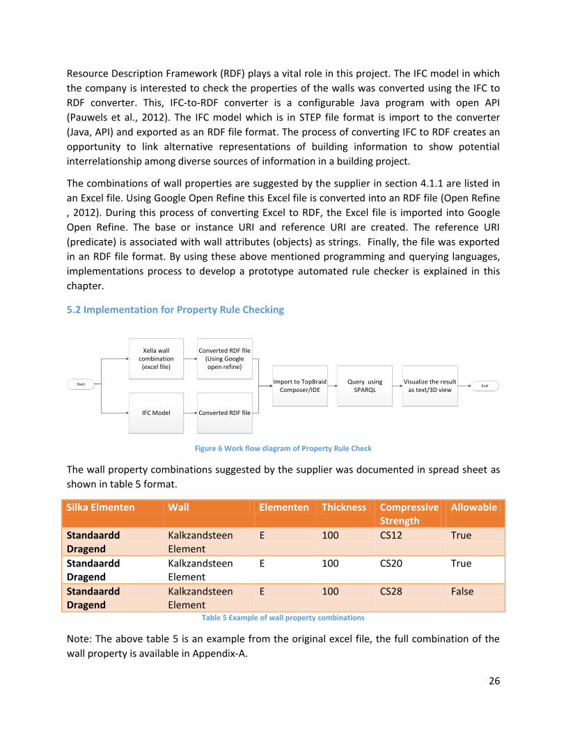
5.2 Implementation for Property Rule Checking
Xella wall combination
(excel file)
Start End
IFC Model
Converted RDF file (Using Google open refine)
Converted RDF file
Import to TopBraidComposer/IDE
Query using SPARQL
Visualize the result as text/3D view
Figure 6 Work flow diagram of Property Rule Check
The wall property combinations suggested by the supplier was documented in spread sheet as
shown in table 5 format.
Silka Elmenten Wall Elementen Thickness Compressive Strength
Allowable
Standaardd Dragend
Kalkzandsteen Element
E 100 CS12 True
Standaardd Dragend
Kalkzandsteen Element
E 100 CS20 True
Standaardd Dragend
Kalkzandsteen Element
E 100 CS28 False
Table 5 Example of wall property combinations
Note: The above table 5 is an example from the original excel file, the full combination of the
wall property is available in Appendix-A.
27
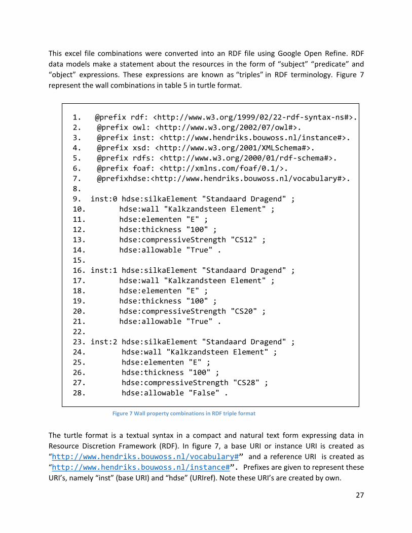
This excel file combinations were converted into an RDF file using Google Open Refine. RDF
data models make a statement about the resources in the form of “subject” “predicate” and
“object” expressions. These expressions are known as “triples” in RDF terminology. Figure 7
represent the wall combinations in table 5 in turtle format.
1. @prefix rdf: <http://www.w3.org/1999/02/22-rdf-syntax-ns#>.
2. @prefix owl: <http://www.w3.org/2002/07/owl#>.
3. @prefix inst: <http://www.hendriks.bouwoss.nl/instance#>.
4. @prefix xsd: <http://www.w3.org/2001/XMLSchema#>.
5. @prefix rdfs: <http://www.w3.org/2000/01/rdf-schema#>.
6. @prefix foaf: <http://xmlns.com/foaf/0.1/>.
7. @prefixhdse:<http://www.hendriks.bouwoss.nl/vocabulary#>.
8.
9. inst:0 hdse:silkaElement "Standaard Dragend" ;
10. hdse:wall "Kalkzandsteen Element" ;
11. hdse:elementen "E" ;
12. hdse:thickness "100" ;
13. hdse:compressiveStrength "CS12" ;
14. hdse:allowable "True" .
15.
16. inst:1 hdse:silkaElement "Standaard Dragend" ;
17. hdse:wall "Kalkzandsteen Element" ;
18. hdse:elementen "E" ;
19. hdse:thickness "100" ;
20. hdse:compressiveStrength "CS20" ;
21. hdse:allowable "True" .
22.
23. inst:2 hdse:silkaElement "Standaard Dragend" ;
24. hdse:wall "Kalkzandsteen Element" ;
25. hdse:elementen "E" ;
26. hdse:thickness "100" ;
27. hdse:compressiveStrength "CS28" ;
28. hdse:allowable "False" .
The turtle format is a textual syntax in a compact and natural text form expressing data in
Resource Discretion Framework (RDF). In figure 7, a base URI or instance URI is created as
“http://www.hendriks.bouwoss.nl/vocabulary#” and a reference URI is created as
“http://www.hendriks.bouwoss.nl/instance#”. Prefixes are given to represent these
URI’s, namely “inst” (base URI) and “hdse” (URIref). Note these URI’s are created by own.
Figure 7 Wall property combinations in RDF triple format
28
The IFC model in which the company is interested to check the properties of the walls was
converted using the IFC to RDF converter. The two RDF files such as: [1] Excel to RDF and [2] IFC
to RDF files are imported and linked using TopBraid Composer.
The list of walls was retrieved from the IFC to RDF model and compared against the Excel to
RDF file using a SPARQL query. The detail of this SPARQL query is explained in section 5.3.2.
Initially, this query was executed using the TopBraid Composer. The output of this SPARQL
query is illustrated in-detail with a screen shot in section 5.4
Using the Python programming language the visualization is conducted. Technically, it could be
achieved by opening the IFC model using IfcOpenshell in the program. Visualization in a three
dimensional views can be achieved by using python OpenCasCade (OCC). The output of this
property rule checking is illustrated in-detail with screen shots in section 5.4
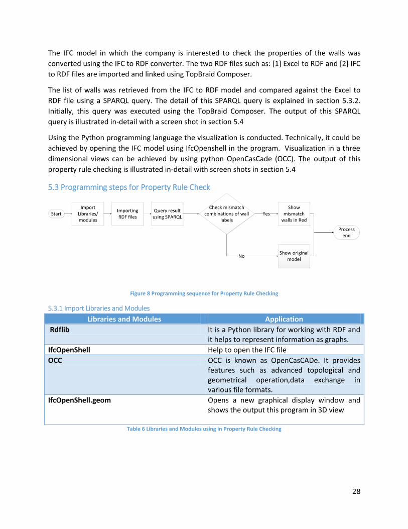
5.3 Programming steps for Property Rule Check
Check mismatch combinations of wall
labels Yes
No
Start
Process end
Import Libraries/modules
Importing RDF files
Query result using SPARQL
Show original model
Show mismatch
walls in Red
Figure 8 Programming sequence for Property Rule Checking
5.3.1 Import Libraries and Modules
Libraries and Modules Application
Rdflib It is a Python library for working with RDF and it helps to represent information as graphs.
IfcOpenShell Help to open the IFC file
OCC OCC is known as OpenCasCADe. It provides features such as advanced topological and geometrical operation,data exchange in various file formats.
IfcOpenShell.geom Opens a new graphical display window and shows the output this program in 3D view
Table 6 Libraries and Modules using in Property Rule Checking
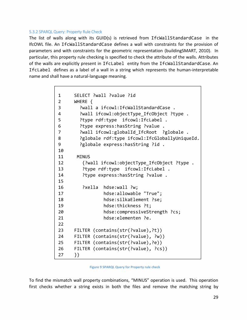
29
5.3.2 SPARQL Query: Property Rule Check
The list of walls along with its GUID(s) is retrieved from IfcWallStandardCase in the
IfcOWL file. An IfcWallStandardCase defines a wall with constraints for the provision of
parameters and with constraints for the geometric representation (buildingSMART, 2010). In
particular, this property rule checking is specified to check the attribute of the walls. Attributes
of the walls are explicitly present in IfcLabel entity from the IfcWallStandardCase. An
IfcLabel defines as a label of a wall in a string which represents the human-interpretable
name and shall have a natural-language meaning.
1 SELECT ?wall ?value ?id
2 WHERE {
3 ?wall a ifcowl:IfcWallStandardCase .
4 ?wall ifcowl:objectType_IfcObject ?type .
5 ?type rdf:type ifcowl:IfcLabel .
6 ?type express:hasString ?value .
7 ?wall ifcowl:globalId_IfcRoot ?globale .
8 ?globale rdf:type ifcowl:IfcGloballyUniqueId.
9 ?globale express:hasString ?id .
10
11 MINUS
12 {?wall ifcowl:objectType_IfcObject ?type .
13 ?type rdf:type ifcowl:IfcLabel .
14 ?type express:hasString ?value .
15
16 ?xella hdse:wall ?w;
17 hdse:allowable "True";
18 hdse:silkaElement ?se;
19 hdse:thickness ?t;
20 hdse:compressiveStrength ?cs;
21 hdse:elementen ?e.
22
23 FILTER (contains(str(?value),?t))
24 FILTER (contains(str(?value), ?w))
25 FILTER (contains(str(?value),?e))
26 FILTER (contains(str(?value), ?cs))
27 }}
To find the mismatch wall property combinations, “MINUS” operation is used. This operation
first checks whether a string exists in both the files and remove the matching string by
Figure 9 SPARQL Query for Property rule check
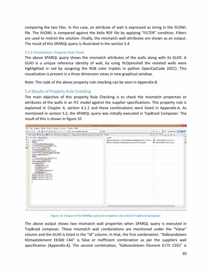
30
comparing the two files. In this case, an attribute of wall is expressed as string in the ifcOWL
file. The ifcOWL is compared against the Xella RDF file by applying “FILTER” condition. Filters
are used to restrict the solution .Finally, the mismatch wall attributes are shown as an output.
The result of this SPARQL query is illustrated in the section 5.4
5.3.3 Visualization: Property Rule Check
The above SPARQL query shows the mismatch attributes of the walls along with its GUID. A
GUID is a unique reference identity of wall, by using IfcOpenshell the violated walls were
highlighted in red by assigning the RGB color triplets in python OpenCasCade (OCC). This
visualization is present in a three dimension views in new graphical window.
Note: The code of the above property rule checking can be seen in Appendix-B
5.4 Results of Property Rule Checking The main objective of this property Rule Checking is to check the mismatch properties or
attributes of the walls in an IFC model against the supplier specifications. This property rule is
explained in Chapter 4, section 4.1.1 and these combinations were listed in Appendix-A. As
mentioned in section 5.2, the SPARQL query was initially executed in TopBraid Composer. The
result of this is shown in figure 10
Figure 10 Output of the SPARQL query for property rule check in TopBraid Composer
The above output shows two mismatch wall properties when SPARQL query is executed in
TopBraid composer. These mismatch wall combinations are mentioned under the “Value”
column and the GUID is listed in the “Id” column. In that, the first combination: “Kalkzandsteen
Klimaatelement EK300 C44” is false or inefficient combination as per the suppliers wall
specification (Appendix-A). The second combination, “Kalkzandsteen Element E175 CS55” is
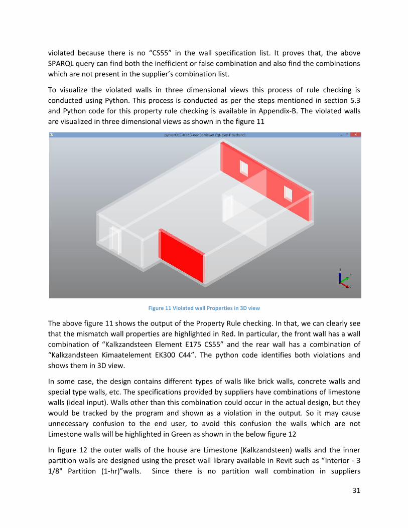
31
violated because there is no “CS55” in the wall specification list. It proves that, the above
SPARQL query can find both the inefficient or false combination and also find the combinations
which are not present in the supplier’s combination list.
To visualize the violated walls in three dimensional views this process of rule checking is
conducted using Python. This process is conducted as per the steps mentioned in section 5.3
and Python code for this property rule checking is available in Appendix-B. The violated walls
are visualized in three dimensional views as shown in the figure 11
Figure 11 Violated wall Properties in 3D view
The above figure 11 shows the output of the Property Rule checking. In that, we can clearly see
that the mismatch wall properties are highlighted in Red. In particular, the front wall has a wall
combination of “Kalkzandsteen Element E175 CS55” and the rear wall has a combination of
“Kalkzandsteen Kimaatelement EK300 C44”. The python code identifies both violations and
shows them in 3D view.
In some case, the design contains different types of walls like brick walls, concrete walls and
special type walls, etc. The specifications provided by suppliers have combinations of limestone
walls (ideal input). Walls other than this combination could occur in the actual design, but they
would be tracked by the program and shown as a violation in the output. So it may cause
unnecessary confusion to the end user, to avoid this confusion the walls which are not
Limestone walls will be highlighted in Green as shown in the below figure 12
In figure 12 the outer walls of the house are Limestone (Kalkzandsteen) walls and the inner
partition walls are designed using the preset wall library available in Revit such as “Interior - 3
1/8" Partition (1-hr)”walls. Since there is no partition wall combination in suppliers
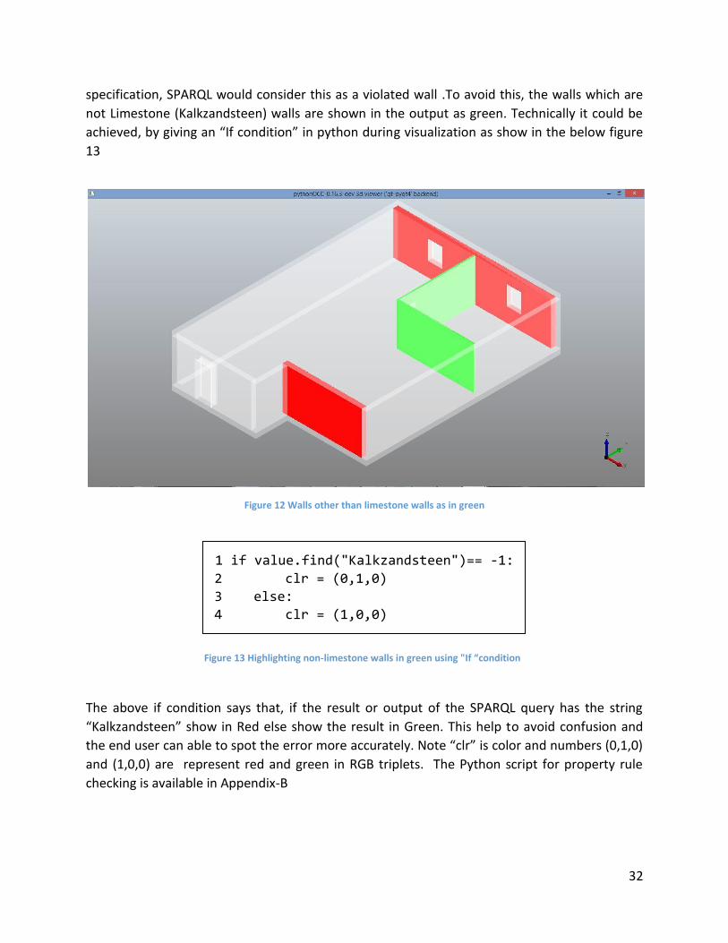
32
specification, SPARQL would consider this as a violated wall .To avoid this, the walls which are
not Limestone (Kalkzandsteen) walls are shown in the output as green. Technically it could be
achieved, by giving an “If condition” in python during visualization as show in the below figure
13
Figure 12 Walls other than limestone walls as in green
1 if value.find("Kalkzandsteen")== -1:
2 clr = (0,1,0)
3 else:
4 clr = (1,0,0)
The above if condition says that, if the result or output of the SPARQL query has the string
“Kalkzandsteen” show in Red else show the result in Green. This help to avoid confusion and
the end user can able to spot the error more accurately. Note “clr” is color and numbers (0,1,0)
and (1,0,0) are represent red and green in RGB triplets. The Python script for property rule
checking is available in Appendix-B
Figure 13 Highlighting non-limestone walls in green using "If “condition
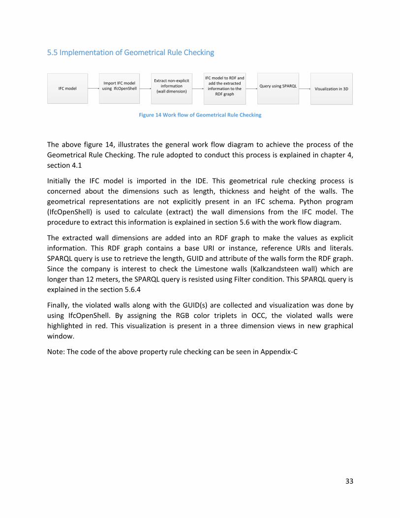
33
5.5 Implementation of Geometrical Rule Checking
IFC model Import IFC model
using IfcOpenShell
Extract non-explicit information
(wall dimension)
IFC model to RDF and add the extracted information to the
RDF graph
Query using SPARQL Visualization in 3D
Figure 14 Work flow of Geometrical Rule Checking
The above figure 14, illustrates the general work flow diagram to achieve the process of the
Geometrical Rule Checking. The rule adopted to conduct this process is explained in chapter 4,
section 4.1
Initially the IFC model is imported in the IDE. This geometrical rule checking process is
concerned about the dimensions such as length, thickness and height of the walls. The
geometrical representations are not explicitly present in an IFC schema. Python program
(IfcOpenShell) is used to calculate (extract) the wall dimensions from the IFC model. The
procedure to extract this information is explained in section 5.6 with the work flow diagram.
The extracted wall dimensions are added into an RDF graph to make the values as explicit
information. This RDF graph contains a base URI or instance, reference URIs and literals.
SPARQL query is use to retrieve the length, GUID and attribute of the walls form the RDF graph.
Since the company is interest to check the Limestone walls (Kalkzandsteen wall) which are
longer than 12 meters, the SPARQL query is resisted using Filter condition. This SPARQL query is
explained in the section 5.6.4
Finally, the violated walls along with the GUID(s) are collected and visualization was done by
using IfcOpenShell. By assigning the RGB color triplets in OCC, the violated walls were
highlighted in red. This visualization is present in a three dimension views in new graphical
window.
Note: The code of the above property rule checking can be seen in Appendix-C
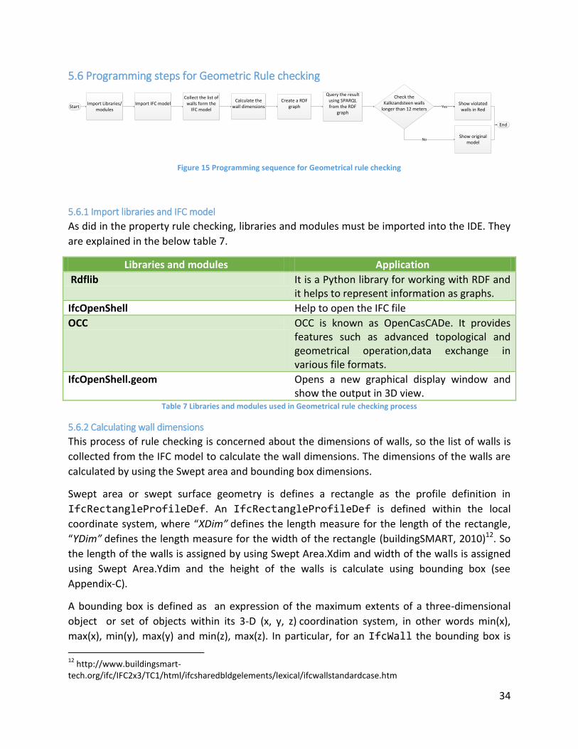
34
5.6 Programming steps for Geometric Rule checking
Start
No
Yes
End
Import Libraries/modules
Import IFC model Collect the list of
walls form the IFC model
Calculate the wall dimensions
Create a RDF graph
Query the result using SPARQL from the RDF
graph
Show violated walls in Red
Show original model
Check the Kalkzandsteen walls
longer than 12 meters Yes
Figure 15 Programming sequence for Geometrical rule checking
5.6.1 Import libraries and IFC model
As did in the property rule checking, libraries and modules must be imported into the IDE. They
are explained in the below table 7.
Libraries and modules Application
Rdflib It is a Python library for working with RDF and it helps to represent information as graphs.
IfcOpenShell Help to open the IFC file
OCC OCC is known as OpenCasCADe. It provides features such as advanced topological and geometrical operation,data exchange in various file formats.
IfcOpenShell.geom Opens a new graphical display window and show the output in 3D view.
Table 7 Libraries and modules used in Geometrical rule checking process
5.6.2 Calculating wall dimensions
This process of rule checking is concerned about the dimensions of walls, so the list of walls is
collected from the IFC model to calculate the wall dimensions. The dimensions of the walls are
calculated by using the Swept area and bounding box dimensions.
Swept area or swept surface geometry is defines a rectangle as the profile definition in
IfcRectangleProfileDef. An IfcRectangleProfileDef is defined within the local
coordinate system, where “XDim” defines the length measure for the length of the rectangle,
“YDim” defines the length measure for the width of the rectangle (buildingSMART, 2010)12. So
the length of the walls is assigned by using Swept Area.Xdim and width of the walls is assigned
using Swept Area.Ydim and the height of the walls is calculate using bounding box (see
Appendix-C).
A bounding box is defined as an expression of the maximum extents of a three-dimensional
object or set of objects within its 3-D (x, y, z) coordination system, in other words min(x),
max(x), min(y), max(y) and min(z), max(z). In particular, for an IfcWall the bounding box is
12
http://www.buildingsmart-tech.org/ifc/IFC2x3/TC1/html/ifcsharedbldgelements/lexical/ifcwallstandardcase.htm
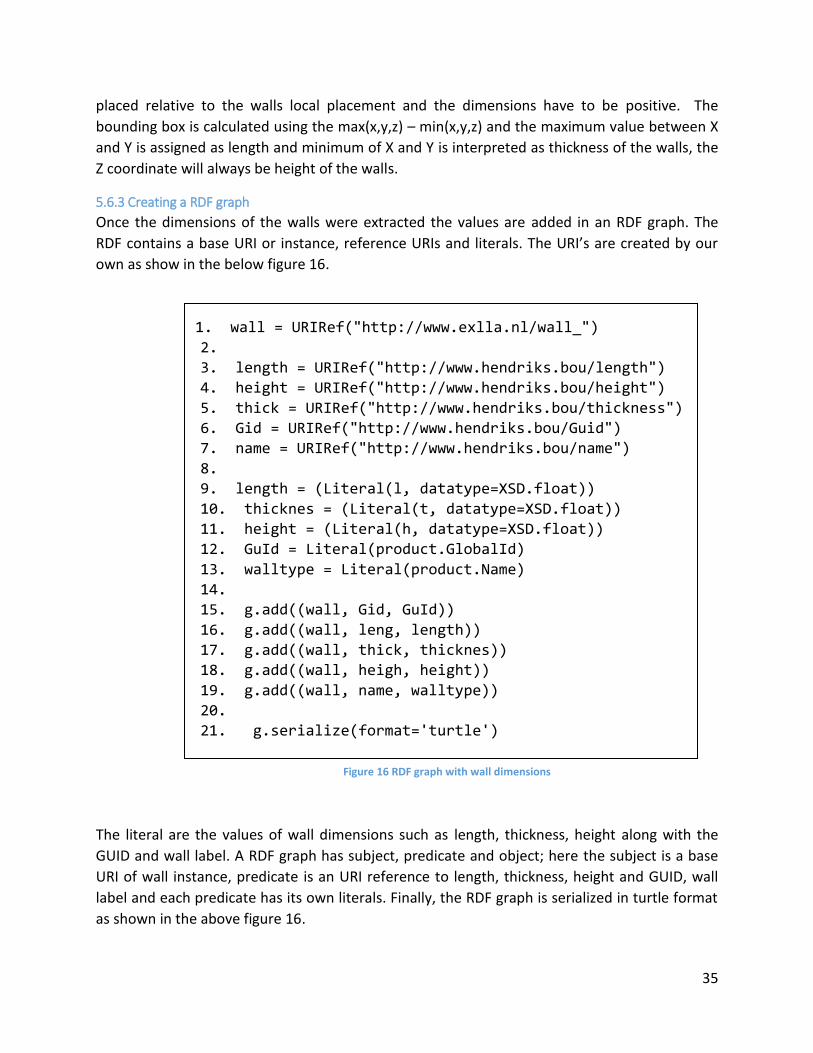
35
placed relative to the walls local placement and the dimensions have to be positive. The
bounding box is calculated using the max(x,y,z) – min(x,y,z) and the maximum value between X
and Y is assigned as length and minimum of X and Y is interpreted as thickness of the walls, the
Z coordinate will always be height of the walls.
5.6.3 Creating a RDF graph
Once the dimensions of the walls were extracted the values are added in an RDF graph. The
RDF contains a base URI or instance, reference URIs and literals. The URI’s are created by our
own as show in the below figure 16.
1. wall = URIRef("http://www.exlla.nl/wall_")
2.
3. length = URIRef("http://www.hendriks.bou/length")
4. height = URIRef("http://www.hendriks.bou/height")
5. thick = URIRef("http://www.hendriks.bou/thickness")
6. Gid = URIRef("http://www.hendriks.bou/Guid")
7. name = URIRef("http://www.hendriks.bou/name")
8.
9. length = (Literal(l, datatype=XSD.float))
10. thicknes = (Literal(t, datatype=XSD.float))
11. height = (Literal(h, datatype=XSD.float))
12. GuId = Literal(product.GlobalId)
13. walltype = Literal(product.Name)
14.
15. g.add((wall, Gid, GuId))
16. g.add((wall, leng, length))
17. g.add((wall, thick, thicknes))
18. g.add((wall, heigh, height))
19. g.add((wall, name, walltype))
20.
21. g.serialize(format='turtle')
The literal are the values of wall dimensions such as length, thickness, height along with the
GUID and wall label. A RDF graph has subject, predicate and object; here the subject is a base
URI of wall instance, predicate is an URI reference to length, thickness, height and GUID, wall
label and each predicate has its own literals. Finally, the RDF graph is serialized in turtle format
as shown in the above figure 16.
Figure 16 RDF graph with wall dimensions
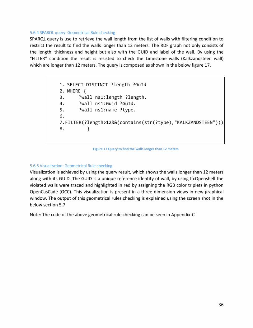
36
5.6.4 SPARQL query: Geometrical Rule checking
SPARQL query is use to retrieve the wall length from the list of walls with filtering condition to
restrict the result to find the walls longer than 12 meters. The RDF graph not only consists of
the length, thickness and height but also with the GUID and label of the wall. By using the
“FILTER” condition the result is resisted to check the Limestone walls (Kalkzandsteen wall)
which are longer than 12 meters. The query is composed as shown in the below figure 17.
1. SELECT DISTINCT ?length ?GuId
2. WHERE {
3. ?wall ns1:length ?length.
4. ?wall ns1:Guid ?GuId.
5. ?wall ns1:name ?type.
6.
7.FILTER(?length>12&&(contains(str(?type),"KALKZANDSTEEN")))
8. }
5.6.5 Visualization: Geometrical Rule checking
Visualization is achieved by using the query result, which shows the walls longer than 12 meters
along with its GUID. The GUID is a unique reference identity of wall, by using IfcOpenshell the
violated walls were traced and highlighted in red by assigning the RGB color triplets in python
OpenCasCade (OCC). This visualization is present in a three dimension views in new graphical
window. The output of this geometrical rules checking is explained using the screen shot in the
below section 5.7
Note: The code of the above geometrical rule checking can be seen in Appendix-C
Figure 17 Query to find the walls longer than 12 meters

37
5.7 Result of Geometrical Rule Checking
Initially a simple model was used to test the code; purposely the two outer walls are drafted
longer than 12 meters. The code checks every wall and shows the violated walls in Red as
shown in figure 18
Figure 18 Walls longer than 12 meters highlighted in red
Finally, a complex model is chosen to test this geometrical rule and this model was issued by
the Hendriks. Since the company is interested to test only for the Limestone walls
(Kalkzandsteen) the result were narrow down using SPARQL query as mentioned in figure 16.
Since there is no limestone walls are longer than 12 meters, in the IFC model. This shows that
all Limestone walls are below 12 meters, the output shows no violations see figure 20.
To double check the result the SPARQL is modified to check the limestone walls smaller than 12
meters as shown figure 19
1. SELECT DISTINCT ?length ?GuId
2. WHERE {
3. ?wall ns1:length ?length.
4. ?wall ns1:Guid ?GuId.
5. ?wall ns1:name ?type.
6.
7.FILTER(?length<12&&(contains(str(?type),"KALKZANDSTEEN")))
8. }
Figure 19 Query modified to check limestone walls smaller than 12
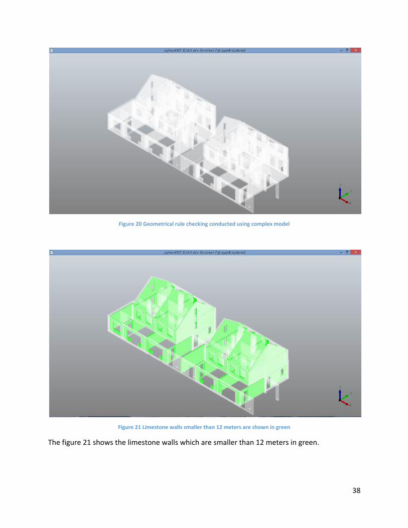
38
Figure 20 Geometrical rule checking conducted using complex model
Figure 21 Limestone walls smaller than 12 meters are shown in green
The figure 21 shows the limestone walls which are smaller than 12 meters in green.
39
5.8.1 Assumptions
In this geometrical rule check process, it was assumed that all walls are straight and rectangular
walls. The company is interested to check the length of the limestone walls. These limestone
walls are always straight and rectangular because these walls are prefabricated by the
suppliers.
5.8.2 Limitations
The use of axis-aligned bounding boxes to determine the dimensions of walls implies
limitations, since the rotation of a bounding box is no longer axis aligned. When the walls are
curved or aligned crossly the length and width of the walls are not accurate.
5.8.3 Recommendation
Bounding box and swept area dimension are applicable only when the walls are straight
and rectangle. These geometrical repetitions are not fully accurate for all types of walls
in an IFC model. There different ways to calculate the dimensions of the walls, the wall
thickness can be obtained directly from the IfcMaterialLayer entity and the length
of the wall can be obtained by navigating into the wall axis shape representation entity
in both IfcWallStandardCase and IfcWall. The height of the walls can be
determined by using bounding box because bounding box take the maximum height of
the walls. In future if the company wants to check the wall dimensions for different
types of walls these IFC schema entities can be taken into account to determine the
dimensions of the wall.
In property rule checking, the automated tool checks only the walls labels. For example,
if the thickness of a wall is stated as 300mm in the label but the actual geometry in the
design may be 250mm. Based on the wall label we cannot conclude that the
specifications is aligned with the wall geometry . So this property rule can be combined
with the geometrical rule to check whether the actual geometry matches its
specifications.
In the 3D visualization, the new graphical window shows only the violated walls in
different color. For example, in geometrical rule checking the output figure 17 shows
the walls longer than 12 meters in red. But it doesn’t show how much the wall exceeds
beyond 12 meters in annotations in the graphical window. In future, IfcOpenShell can
focuses on adding annotations in the visualization helps end user to have clear about
the results.
40
In the HBO BIM norms, there are many rules and requirements are stated for IFC objects
such as doors, windows, beams, columns, roofs, floors etc. Each IFC objects has its own
boundary conditions and property sets. Keep this research as a reference the properties
(supplier catalog) can be converted into a RDF file format. As mentioned before,
property (attribute) information of an IFC object is explicitly present in an IFC model. By
converting the IFC model into an IfcOWL gives an opportunity to compare the design
against the supplier specifications using SPARQL query language. As result, the BIM
manager can find that the designer uses the correct or allowable specifications in the
actual design.
Geometry (boundary condition) of an IFC object is not explicitly present in the IFC
model. Using Python programming language along with the IfcOpenShell (software
library) the geometrical information can be calculated. The calculated geometrical
values can be added into an RDF graph to make the information explicit. The rules can
be formalized using SPARQL query.
The results of this rule checking process can be visualized in three dimensional views
using python libraries and modules.
This gives an opportunity to convert maximum number of rules in the HBO BIM norm
into an automated rule checking process in the near future.
41
Chapter-6
6 Conclusion In this chapter the overall conclusion is explained based on this rule checking process. Initially,
the answers to the research questions are briefed. Finally, the contribution of this prototype
automated rule checker to the society and industry is briefed.
6.1 Answer(s) to research questions
In this section initially, the sub-questions answers the specific process of this development
project. Finally, the main research question answers the overall process as summary.
Sub-Questions:
What are the rules chosen for this automated rule checking process and why it is
stated in the in-house BIM norms?
In HBO BIM norms there are many rules and requirements were proposed for the IFC
standards. This graduations project is focused on IfcWallStandardCase rules and
requirements. The rules are further categorized into [1] Property Rules and [2]
Geometrical Rules.
A property of a wall defines the attribute of a wall such type, thickness and compressive
strength. In property rules, the lists of wall properties are suggested by the supplier.
Since the suppler fabricates different types of walls, this property rule set act as catalog.
From this catalog the client (Hendriks) can choose a particular type of wall based on
their requirement. The designers must design the exact specification chosen by the
client. Based on the design specification the supplier fabricates the walls and delivered
to site.
Geometrical rule defines the geometry or dimensions of the wall. In this case, the rule
states that the wall should not be longer than 12 meters because the prefabricated
walls are lifted using a crane in the site. This crane has the range of 12 meters, if the
walls are designed and fabricated beyond 12 meters the workers have dismantle the
crane. This process is time consuming and inefficient in site.
What data do we need to conduct this automated rule checking process?
To conduct this automated rule checking process, the rules written in natural language
and IFC models are collected from the company. Since this automated rule checker is
based on linked data approach, the data are converted into Resource Description
Framework (RDF) format. The IFC model in which the rule checking process was
executed is converted into IfcOWL format using the Java API converter. The wall
properties are listed in an Excel file was converted into an RDF file using Google Open
Refine.
42
How this automated rule checker is beneficial for the BIM manager for decision
making?
Once this automated rule checker is developed the BIM manager can import models
into this rule checker. This rule checker is developed to check the wall properties and
dimensions. By executing the SPARQL query, along with Python program the mismatch
wall properties and violated wall length are visualized in a three dimensional view.
Visualizing the result helps the BIM manager and other stakeholders to take rapid-
decision making on those issues. This rule checker is more beneficial when the rule
checking process is conducted in the design phase of a building. This rule checking
process helps to avoid unnecessary problems during the execution phase of the building
life cycle. Overall, this automated rule checker reduces time consumption during the
process of rule checking.
Main Question:
How to develop an Automated Rule checker for in-house BIM norms to check and
validate building models?
This question is the baseline of this whole thesis. To develop this automated rule
checker the project is divided into three major phases. They are: [1] Problem analysis,
[2] Methodology and [3] Implementation.
In the problem analysis phase, problems in the current rule checking process were
analyzed based on the expert interviews from the company.
During the Methodology phase, the solution for the problem exists in the current rule
checking process is formulated based on literature studies. The methodology is divided
into five different processes. They are: [1] Select the rules form the in-house BIM norms
and collect the models, [2] Convert the rules written in natural languages into computer
readable format, [3] Convert data such as IFC model and suppler requirement (Excel file)
into RDF file format, [4] execute the SPARQL along with python program and [5]
visualize the result in three dimensional views.
Finally the implementation phase of rule checking is divided into two categories namely:
[1] Property rule checking and [2] Geometrical rule checking.
In property rule checking, the supplier’s wall properties listed in an Excel file and the IFC
model are converted into RDF files. Using SPARQL query the mismatch wall properties
are identified. The result of this property rule checking is visualized in a three
dimensional view using Python libraries and modules.
In geometrical rule checking process, the geometrical information is not explicit in the
IFC schema. In this case, python program is used to calculate (extract) the wall
dimensions. The dimensions of the walls are added in an RDF graph to make the
43
information explicit. Using SPARQL query, the walls longer than 12 meters are identified.
The output of this geometrical checking is visualized in a three dimensional view using
Python libraries and modules.
6.2 Social Relevance Due to globalization, clients around the world became more demanding and sophisticated
towards the requirements and services offered by the construction industry. This demanding
nature makes a huge pressure on the AEC industry to fulfill the clients expected services. The
constructions industry is in a position to adopt new smart solutions and services for better
coordination and communication among the stakeholders. An effective collaboration requires
coordinated communication and communicated coordination. In recent years, many smart
solutions and services were developed in the construction industry. One of the emerging
technologies is Building Information Modeling (BIM). BIM has many usages, such as clash
detection, visualization, construction planning and monitoring cost estimation of the
construction project.
This graduation project adds a small contribution to the constructions industry by developing a
prototype of an automated rule checker. This tool helps to check the properties and
geometrical conditions of a wall in the BIM model. If any violations are found during the rule
checking process, it will be highlighted in a 3D view. Visualization of result helps for effective
communications and collaborations among the stakeholders. Based on the visualization report,
rapid decision making can be achieved. As a result, it will reduce the analyzing cost and save
time. This helps to avoid unnecessary delay in the project. Avoiding delays increase profit for
both the client and construction industry.
Investing on a commercial rule checking tools need high investment and high level of
programming knowledge is require to customize new rules. This automated rule checker is
developed based on Linked data approach, the process of querying and checking the building
models can be conducted without expensive and heavy technical or programming
requirements. The Semantic web technology and Linked data approach give an opportunity to
link or compare cross domain information of the construction industry using a common data
format, know as RDF. However, to make profit out this automated rule checker based on Linked
data format the programs must also have the integrate capabilities that enable the interaction
with these types of information represented using the RDF data model.
This in-house automated rule checker can be shared among the stakeholders (open
environment) to check the models on their own. If any violations arise during the process of
rule checking, it can be rectified by designer himself. This leads to self repairing and reduce the
iteration process of rule checking among the stakeholders. On the business side, having our
own in-house rule checker gives a unique identity to the company in the construction market.

44
45
Bibliography
buildingSMART International . (2016, December 31). Home / Specifications / IFC Overview. Retrieved
January 15, 2016, from buildingSMART International : http://www.buildingsmart-
tech.org/specifications/ifc-overview
EN Eurocodes. (2013, July 1). Retrieved June 12, 2016, from The EN Eurocodes:
http://eurocodes.jrc.ec.europa.eu/
Health and Safety Authority. (2009). Clients in Construction: Best Practice Guidance. Dublin: Health and
Safety Authority.
Albino, V., Pontrandolfo, P., & Scozzi, B. (2002). Analysis of information flows to enhance the
coordination of production processes. Int. J. Production Economics , 7-19.
Ameen, A., Rahman Khan, K. U., & Rani, B. (2015). SemRPer - A Rule based Personalization System for
Semantic Web. International Journal Web Applications , 23-38.
Azhar, S., Nadeem, A., Mok, J. Y., & Leung, B. H. (2008). Building Information Modeling (BIM): A New
Paradigm for Visual Interactive Modeling and Simulation for Construction Projects. Auburn: Auburn
University, Auburn.
Bazjanac, V., & Crawley, D. B. (2000). THE IMPLEMENTATION OF INDUSTRY FOUNDATION CLASSES IN
SIMULATION TOOLS FOR THE BUILDING INDUSTRY. California : Lawrence Berkeley National Laboratory.
Beetz, J., Laat, R. d., Berlo, L. V., & Helm, P. v. (2010). Towards an Open Building Information Model
Server Report on the progress of an open IFC framework. Eindhoven: Eindhoven University of
Technology.
Berggren, C., Soderlund, J., & Anderson, C. (2001). Clients,Contractors, and Consultants: The
Consequence of Organizational Fragmentation in Contempaory Project Enviroment. Project
Management Journal , 39-48.
Berlo, L. v., Beetz, J., Bos, p., Hendriks, H., & Tongeren, v. R. (2013). Collaborative engineering with IFC:
new insights and technology. Delft: Netherlands organisation for Applied Scientific Research TNO.
bimserver.org. (2011, march 21). Home. Retrieved August 3, 2016, from bimserver.org:
http://bimserver.org/
Bizer, C., Heath, T., & Berners-Lee, T. (2009). Linked Data - The Story So Far. International Journal on
Semantic Web and Information Systems , 53-72.
Building regulations. (2012). Building regulations. Retrieved June 12, 2016, from Answers for Business:
http://www.answersforbusiness.nl/regulation/building-regulations
buildingSMART. (2016, December 31). Home / Future / Linked Data / ifcOWL. Retrieved Janury 16, 2016,
from buildingSMART: http://www.buildingsmart-tech.org/future/linked-data/ifcowl
buildingSMART. (2010, September 5). Home:IfcWallStandardCase. Retrieved June 22, 2016, from
buildingSMART: http://www.buildingsmart-
tech.org/ifc/IFC2x3/TC1/html/ifcsharedbldgelements/lexical/ifcwallstandardcase.htm
46
Campbell, L. M., & MacNeill, S. (2010). The Semantic Web Linked and Open Data. UK: JISC CETIS.
Charalambous, G., Thorpe, T., Yeomans, S., & Doughty, N. (2013). COLLABORATIVE BIM IN THE CLOUD
AND THE COMMUNICATION TOOLS TO SUPPORT IT. China: Tsinghua University.
Christiansson, P., Svidt, K., Pedersen, K. B., & Dybro, U. (2010). USER PARTICIPATION IN THE BUILDING
PROCESS. Journal of Information Technology in Construction , 1874-4753.
Costa, G., & Pauwels, P. (2015). Building product suggestions for a BIM model based on rule sets and a
semantic reasoning engine. The Netherlands: Eindhoven.
Curry, E., Donnell, J. O., & Corry, E. (2012). Building Optimisation using Scenario Modeling and Linked
Data. NUI Galway.
Eastman, C., Lee, J. m., suk Jeong, Y., & kook Lee, J. (2009). Automatic rule-based checking of building
designs. Automation in Construction , 1011–1033.
Fischer, M., & Kam, C. (2002). ). PM4D Final Report€, CIFE Technical Report. USA: Stanford University.
Government of Singapore. (2016). About Us. Retrieved Jane 12, 2016, from Corenet :
https://www.corenet.gov.sg
Hendriks Bouw en Ontwikkeling. (2016). HBO BIM Norm. Oss, The Netherlands : Hendriks.
Hitzler, P. (2011). Knowledge Representation for the Semantic Web. Dayton: Wright State University.
Hjelseth. (2012). Converting performance based regulations into computable rules in BIM based model
checking software. eWork and eBusiness in Architecture, Engineering and Construction , 461-469.
Hjelseth, E., & Nisbet, N. (2011). CAPTURING NORMATIVE CONSTRAINTS BY USE OF THE SEMANTIC
MARK-UP RASE METHODOLOGY. Norway: Department of Mathematical Sciences and Technology.
Jetbrains. (2016, December 31). Main . Retrieved June 20, 2016, from jetbrains:
https://www.jetbrains.com/pycharm/
Kasim, T., Li, H., Rezgui, Y., & Beach, T. (2013). AUTOMATED SUSTAINABILITY COMPLIANCE CHECKING
PROCESS: PROOF OF CONCEPT. 13th International Conference on Construction Applications of Virtual
Reality, (pp. 30-41). London.
Krijnen, T. (2015, October 7). Home. Retrieved January 15, 2016, from IfcOpenShell:
http://ifcopenshell.org/index.html
Lee, D. Y., Chi, H. l., Wang, J., Wang, X., & Park, C. S. (2016). A linked data system framework for sharing
construction defect information using ontologies and BIM environments. Automation in Construction ,
102–113.
Nash, S., Chinyio, E., Gameson, R., & Suresh, S. (2010). THE DYNAMISM OF STAKEHOLDERS’ POWER IN
CONSTRUCTION PROJECTS. Association of Researchers in Construction Management , 471-480.
Open Refine . (2012, October 2). Home. Retrieved June 20, 2016, from Open Refine :
http://openrefine.org/
47
OWL. (2012, December 11). Web Ontology Language (OWL). Retrieved May 25, 2016, from W3C:
https://www.w3.org/2001/sw/wiki/OWL
Park, S., & Kim, I. (2015). BIM-BASED QUALITY CONTROL FOR SAFETY ISSUES IN THE DESIGN AND
CONSTRUCTION PHASES. International Journal of Architectural Research , 111-129.
Paschke, A., & Boley, H. (2009). Rule Markup Languages and Semantic Web Rule Languages. IGI Global.
Pauwels, P. (2014). Supporting Decision-Making in the Building Life-Cycle Using Linked Building Data.
Buildings , 549-579.
Pauwels, P., & Oraskari, J. (2012, December 15). Retrieved January 17, 2016, from GitHUB:
https://github.com/mmlab/IFC-to-RDF-converter
Pauwels, P., & Zhang, S. (2015). Semantic Rule-checking for Regulation Compliance Checking: An
Overview of Strategies and Approaches. Proc. of the 32nd CIB W78 Conference (pp. 619-628). Eindhoven
The Netherlands: Ghent University.
Pauwels, P., Deursenc, D. V., Verstraeten, R., Roo, J. D., Meyer, R. D., Wallec, R. V., et al. (2010). A
semantic rule checking environment for building performance checking. Belgium: Ghent University.
Perez, J., Arenas, M., & Gutierrez, C. (2006). Semantics and Complexity of SPARQL. Chile: Universidad de
Talca.
Preidel, C., & Borrmann, A. (2015). Automated Code Compliance Checking Based on a Visual Language
and Building Information Modeling. München: Technische Universität München.
Python. (2016, January 12). Python: Doc. Retrieved June 1, 2016, from Python:
https://www.python.org/doc/essays/blurb/
Rillaer, D. V., Burger, J., Ploegmakers, R., & Mitossi, V. (2013). Rgd BIM Standard. The Hague, The
Netherlands: Rijksgebouwendienst.
Tan, X., & Hammad, A. (2010). Automated code compliance checking for building envelope design.
Journal of Computing in Civil Engineering , 203-211.
TopBraid Composer. (2016, December 31). About Us:. Retrieved June 20, 2016, from TopQuadrant:
http://www.topquadrant.com
VENUGOPAL, M., EASTMAN, C. M., & TEIZER, J. (2012). An Ontological Approach to Building Information
Model Exchanges in the Precast/Pre-stressed Concrete Industry. Construction Research Congress , 1114-
1123.
VOLK, R., STENGEL, J., & SCHULTMANN, F. (2014). Building Information Modeling (BIM) for existing
buildings – literature review and future needs. Automation in Construction , 109-127.
Vries, B. d., Allameh, E., & Heidari Jozam, M. (2012). Smart-BIM (Building Information Modeling).
Eindhoven: Eindhoven University of Technology.
W3C. (2012, November 7). Main Page . Retrieved March 14, 2016, from Semantic Web:
http://semanticweb.org/wiki/Main_Page.html
48
W3C. (2004, Feburary 10). RDF Primer. Retrieved June 15, 2016, from W3C.
W3C. (2014, February 25). RDF Schema 1.1. Retrieved March 12, 2016, from W3C RDF:
https://www.w3.org/TR/rdf-schema/
W3C. (2013, March 21). SPARQL 1.1 Query Language. Retrieved March 15, 2016, from W3C:
https://www.w3.org/TR/sparql11-query/
W3C. (2013, March 21). SPARQL 1.1 Query Language. Retrieved June 22, 2016, from W3C:
https://www.w3.org/TR/sparql11-query/#neg-notexists-minus
Yan, H., & Damian, P. (2008). Benefits and Barriers of Building Information Modelling. UK: Loughborough
University.
Zhang, C., Beetz, J., & Weise, M. (2014). INTEROPERABLE VALIDATION FOR IFC BUILDING MODELS USING
OPEN STANDARDS. Journal of Information Technology in Construction , 1874-4753.
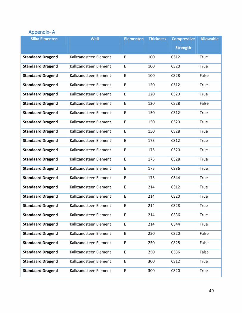
49
Appendix- A Silka Elmenten Wall
Elementen Thickness Compressive
Strength
Allowable
Standaard Dragend Kalkzandsteen Element E 100 CS12 True
Standaard Dragend Kalkzandsteen Element E 100 CS20 True
Standaard Dragend Kalkzandsteen Element E 100 CS28 False
Standaard Dragend Kalkzandsteen Element E 120 CS12 True
Standaard Dragend Kalkzandsteen Element E 120 CS20 True
Standaard Dragend Kalkzandsteen Element E 120 CS28 False
Standaard Dragend Kalkzandsteen Element E 150 CS12 True
Standaard Dragend Kalkzandsteen Element E 150 CS20 True
Standaard Dragend Kalkzandsteen Element E 150 CS28 True
Standaard Dragend Kalkzandsteen Element E 175 CS12 True
Standaard Dragend Kalkzandsteen Element E 175 CS20 True
Standaard Dragend Kalkzandsteen Element E 175 CS28 True
Standaard Dragend Kalkzandsteen Element E 175 CS36 True
Standaard Dragend Kalkzandsteen Element E 175 CS44 True
Standaard Dragend Kalkzandsteen Element E 214 CS12 True
Standaard Dragend Kalkzandsteen Element E 214 CS20 True
Standaard Dragend Kalkzandsteen Element E 214 CS28 True
Standaard Dragend Kalkzandsteen Element E 214 CS36 True
Standaard Dragend Kalkzandsteen Element E 214 CS44 True
Standaard Dragend Kalkzandsteen Element E 250 CS20 False
Standaard Dragend Kalkzandsteen Element E 250 CS28 False
Standaard Dragend Kalkzandsteen Element E 250 CS36 False
Standaard Dragend Kalkzandsteen Element E 300 CS12 True
Standaard Dragend Kalkzandsteen Element E 300 CS20 True
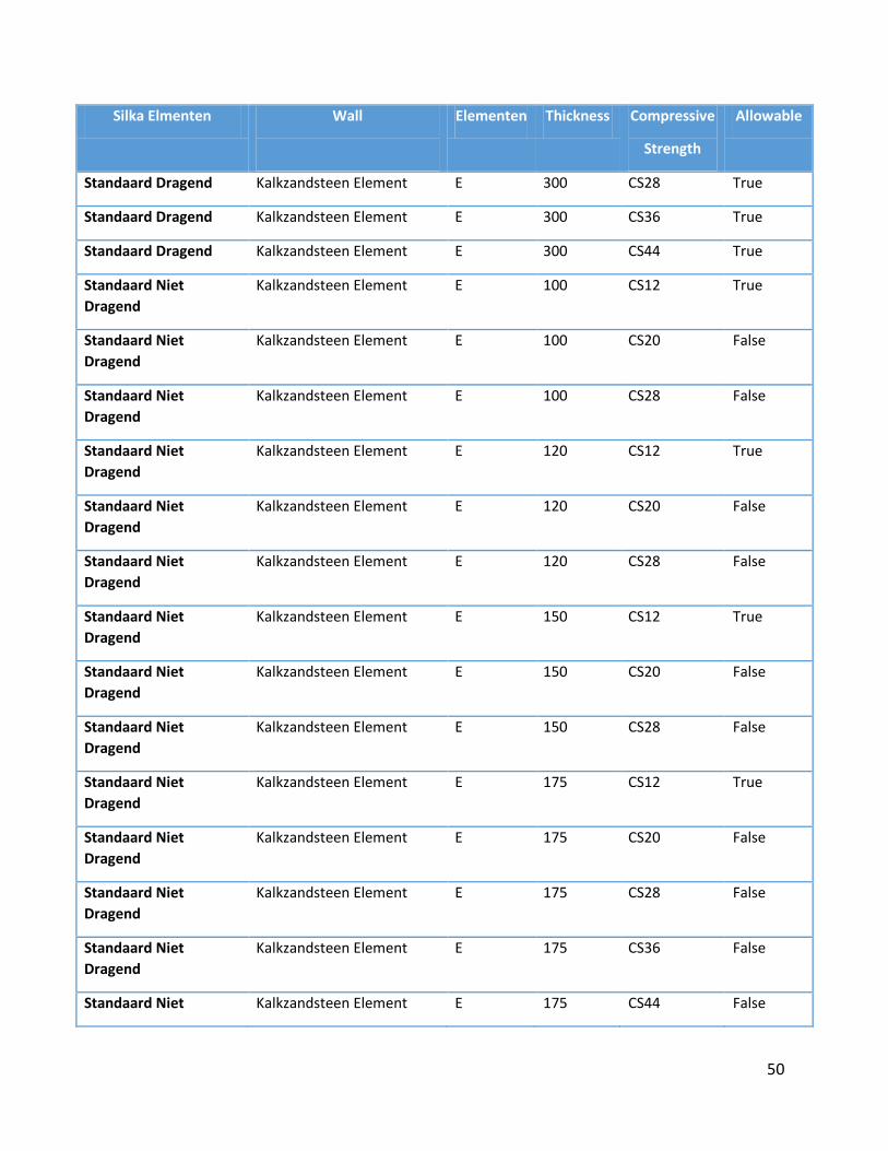
50
Silka Elmenten Wall
Elementen Thickness Compressive
Strength
Allowable
Standaard Dragend Kalkzandsteen Element E 300 CS28 True
Standaard Dragend Kalkzandsteen Element E 300 CS36 True
Standaard Dragend Kalkzandsteen Element E 300 CS44 True
Standaard Niet
Dragend
Kalkzandsteen Element E 100 CS12 True
Standaard Niet
Dragend
Kalkzandsteen Element E 100 CS20 False
Standaard Niet
Dragend
Kalkzandsteen Element E 100 CS28 False
Standaard Niet
Dragend
Kalkzandsteen Element E 120 CS12 True
Standaard Niet
Dragend
Kalkzandsteen Element E 120 CS20 False
Standaard Niet
Dragend
Kalkzandsteen Element E 120 CS28 False
Standaard Niet
Dragend
Kalkzandsteen Element E 150 CS12 True
Standaard Niet
Dragend
Kalkzandsteen Element E 150 CS20 False
Standaard Niet
Dragend
Kalkzandsteen Element E 150 CS28 False
Standaard Niet
Dragend
Kalkzandsteen Element E 175 CS12 True
Standaard Niet
Dragend
Kalkzandsteen Element E 175 CS20 False
Standaard Niet
Dragend
Kalkzandsteen Element E 175 CS28 False
Standaard Niet
Dragend
Kalkzandsteen Element E 175 CS36 False
Standaard Niet Kalkzandsteen Element E 175 CS44 False
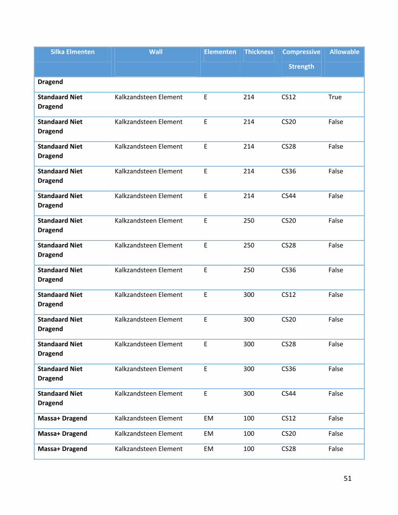
51
Silka Elmenten Wall
Elementen Thickness Compressive
Strength
Allowable
Dragend
Standaard Niet
Dragend
Kalkzandsteen Element E 214 CS12 True
Standaard Niet
Dragend
Kalkzandsteen Element E 214 CS20 False
Standaard Niet
Dragend
Kalkzandsteen Element E 214 CS28 False
Standaard Niet
Dragend
Kalkzandsteen Element E 214 CS36 False
Standaard Niet
Dragend
Kalkzandsteen Element E 214 CS44 False
Standaard Niet
Dragend
Kalkzandsteen Element E 250 CS20 False
Standaard Niet
Dragend
Kalkzandsteen Element E 250 CS28 False
Standaard Niet
Dragend
Kalkzandsteen Element E 250 CS36 False
Standaard Niet
Dragend
Kalkzandsteen Element E 300 CS12 False
Standaard Niet
Dragend
Kalkzandsteen Element E 300 CS20 False
Standaard Niet
Dragend
Kalkzandsteen Element E 300 CS28 False
Standaard Niet
Dragend
Kalkzandsteen Element E 300 CS36 False
Standaard Niet
Dragend
Kalkzandsteen Element E 300 CS44 False
Massa+ Dragend Kalkzandsteen Element EM 100 CS12 False
Massa+ Dragend Kalkzandsteen Element EM 100 CS20 False
Massa+ Dragend Kalkzandsteen Element EM 100 CS28 False
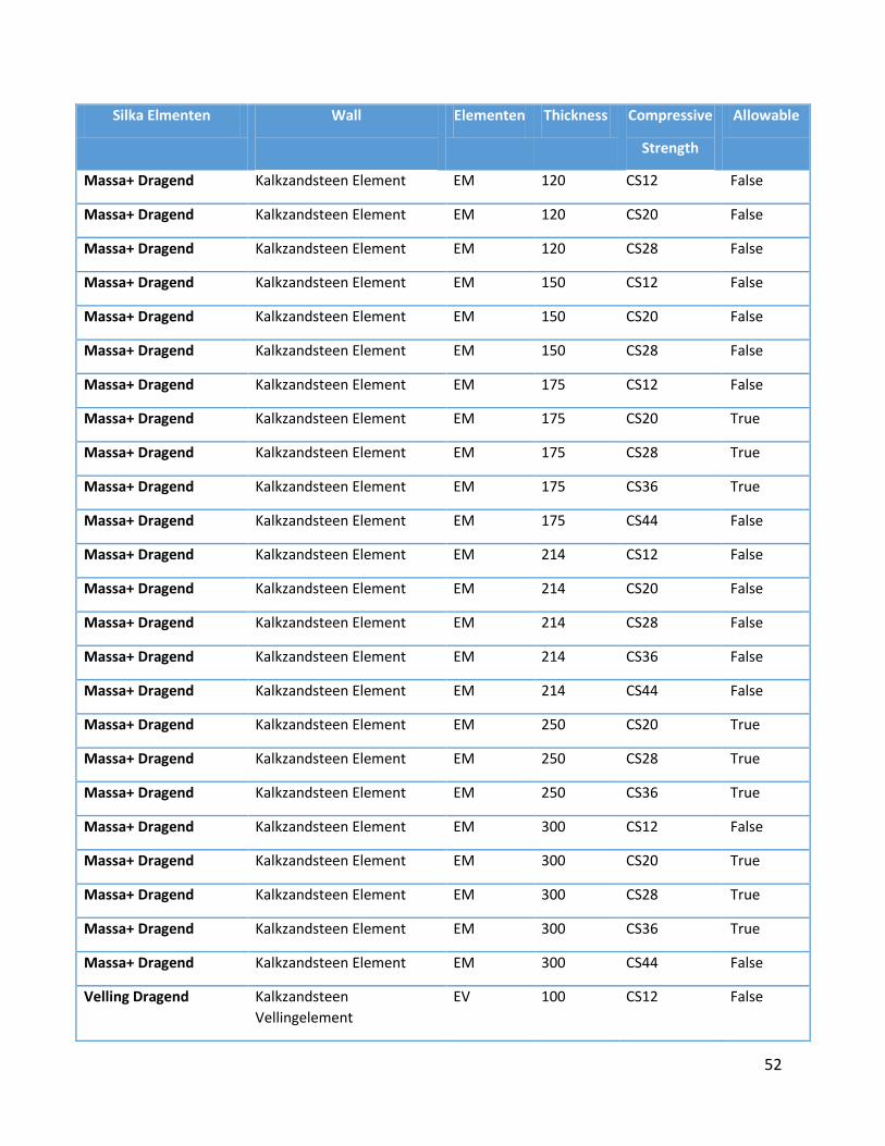
52
Silka Elmenten Wall
Elementen Thickness Compressive
Strength
Allowable
Massa+ Dragend Kalkzandsteen Element EM 120 CS12 False
Massa+ Dragend Kalkzandsteen Element EM 120 CS20 False
Massa+ Dragend Kalkzandsteen Element EM 120 CS28 False
Massa+ Dragend Kalkzandsteen Element EM 150 CS12 False
Massa+ Dragend Kalkzandsteen Element EM 150 CS20 False
Massa+ Dragend Kalkzandsteen Element EM 150 CS28 False
Massa+ Dragend Kalkzandsteen Element EM 175 CS12 False
Massa+ Dragend Kalkzandsteen Element EM 175 CS20 True
Massa+ Dragend Kalkzandsteen Element EM 175 CS28 True
Massa+ Dragend Kalkzandsteen Element EM 175 CS36 True
Massa+ Dragend Kalkzandsteen Element EM 175 CS44 False
Massa+ Dragend Kalkzandsteen Element EM 214 CS12 False
Massa+ Dragend Kalkzandsteen Element EM 214 CS20 False
Massa+ Dragend Kalkzandsteen Element EM 214 CS28 False
Massa+ Dragend Kalkzandsteen Element EM 214 CS36 False
Massa+ Dragend Kalkzandsteen Element EM 214 CS44 False
Massa+ Dragend Kalkzandsteen Element EM 250 CS20 True
Massa+ Dragend Kalkzandsteen Element EM 250 CS28 True
Massa+ Dragend Kalkzandsteen Element EM 250 CS36 True
Massa+ Dragend Kalkzandsteen Element EM 300 CS12 False
Massa+ Dragend Kalkzandsteen Element EM 300 CS20 True
Massa+ Dragend Kalkzandsteen Element EM 300 CS28 True
Massa+ Dragend Kalkzandsteen Element EM 300 CS36 True
Massa+ Dragend Kalkzandsteen Element EM 300 CS44 False
Velling Dragend Kalkzandsteen
Vellingelement
EV 100 CS12 False
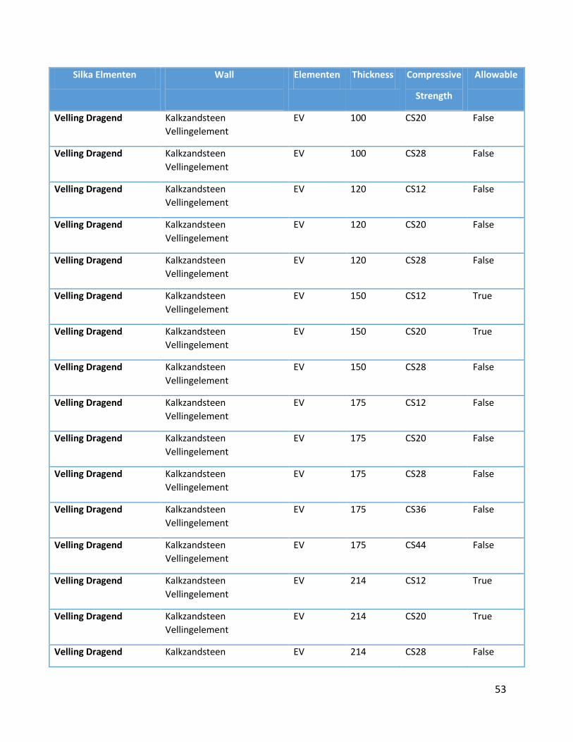
53
Silka Elmenten Wall
Elementen Thickness Compressive
Strength
Allowable
Velling Dragend Kalkzandsteen
Vellingelement
EV 100 CS20 False
Velling Dragend Kalkzandsteen
Vellingelement
EV 100 CS28 False
Velling Dragend Kalkzandsteen
Vellingelement
EV 120 CS12 False
Velling Dragend Kalkzandsteen
Vellingelement
EV 120 CS20 False
Velling Dragend Kalkzandsteen
Vellingelement
EV 120 CS28 False
Velling Dragend Kalkzandsteen
Vellingelement
EV 150 CS12 True
Velling Dragend Kalkzandsteen
Vellingelement
EV 150 CS20 True
Velling Dragend Kalkzandsteen
Vellingelement
EV 150 CS28 False
Velling Dragend Kalkzandsteen
Vellingelement
EV 175 CS12 False
Velling Dragend Kalkzandsteen
Vellingelement
EV 175 CS20 False
Velling Dragend Kalkzandsteen
Vellingelement
EV 175 CS28 False
Velling Dragend Kalkzandsteen
Vellingelement
EV 175 CS36 False
Velling Dragend Kalkzandsteen
Vellingelement
EV 175 CS44 False
Velling Dragend Kalkzandsteen
Vellingelement
EV 214 CS12 True
Velling Dragend Kalkzandsteen
Vellingelement
EV 214 CS20 True
Velling Dragend Kalkzandsteen EV 214 CS28 False
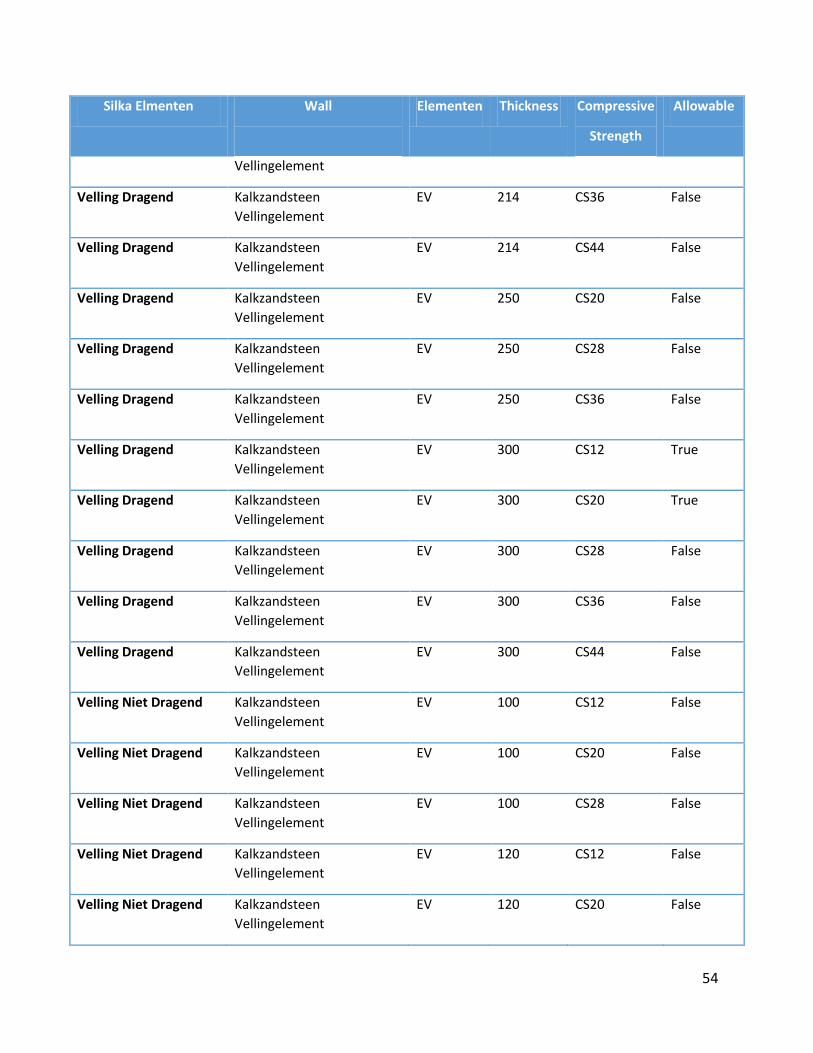
54
Silka Elmenten Wall
Elementen Thickness Compressive
Strength
Allowable
Vellingelement
Velling Dragend Kalkzandsteen
Vellingelement
EV 214 CS36 False
Velling Dragend Kalkzandsteen
Vellingelement
EV 214 CS44 False
Velling Dragend Kalkzandsteen
Vellingelement
EV 250 CS20 False
Velling Dragend Kalkzandsteen
Vellingelement
EV 250 CS28 False
Velling Dragend Kalkzandsteen
Vellingelement
EV 250 CS36 False
Velling Dragend Kalkzandsteen
Vellingelement
EV 300 CS12 True
Velling Dragend Kalkzandsteen
Vellingelement
EV 300 CS20 True
Velling Dragend Kalkzandsteen
Vellingelement
EV 300 CS28 False
Velling Dragend Kalkzandsteen
Vellingelement
EV 300 CS36 False
Velling Dragend Kalkzandsteen
Vellingelement
EV 300 CS44 False
Velling Niet Dragend Kalkzandsteen
Vellingelement
EV 100 CS12 False
Velling Niet Dragend Kalkzandsteen
Vellingelement
EV 100 CS20 False
Velling Niet Dragend Kalkzandsteen
Vellingelement
EV 100 CS28 False
Velling Niet Dragend Kalkzandsteen
Vellingelement
EV 120 CS12 False
Velling Niet Dragend Kalkzandsteen
Vellingelement
EV 120 CS20 False
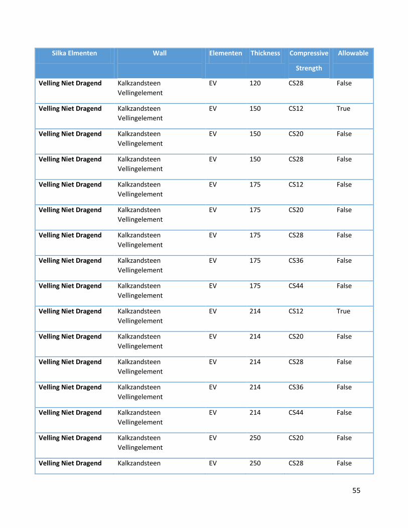
55
Silka Elmenten Wall
Elementen Thickness Compressive
Strength
Allowable
Velling Niet Dragend Kalkzandsteen
Vellingelement
EV 120 CS28 False
Velling Niet Dragend Kalkzandsteen
Vellingelement
EV 150 CS12 True
Velling Niet Dragend Kalkzandsteen
Vellingelement
EV 150 CS20 False
Velling Niet Dragend Kalkzandsteen
Vellingelement
EV 150 CS28 False
Velling Niet Dragend Kalkzandsteen
Vellingelement
EV 175 CS12 False
Velling Niet Dragend Kalkzandsteen
Vellingelement
EV 175 CS20 False
Velling Niet Dragend Kalkzandsteen
Vellingelement
EV 175 CS28 False
Velling Niet Dragend Kalkzandsteen
Vellingelement
EV 175 CS36 False
Velling Niet Dragend Kalkzandsteen
Vellingelement
EV 175 CS44 False
Velling Niet Dragend Kalkzandsteen
Vellingelement
EV 214 CS12 True
Velling Niet Dragend Kalkzandsteen
Vellingelement
EV 214 CS20 False
Velling Niet Dragend Kalkzandsteen
Vellingelement
EV 214 CS28 False
Velling Niet Dragend Kalkzandsteen
Vellingelement
EV 214 CS36 False
Velling Niet Dragend Kalkzandsteen
Vellingelement
EV 214 CS44 False
Velling Niet Dragend Kalkzandsteen
Vellingelement
EV 250 CS20 False
Velling Niet Dragend Kalkzandsteen EV 250 CS28 False
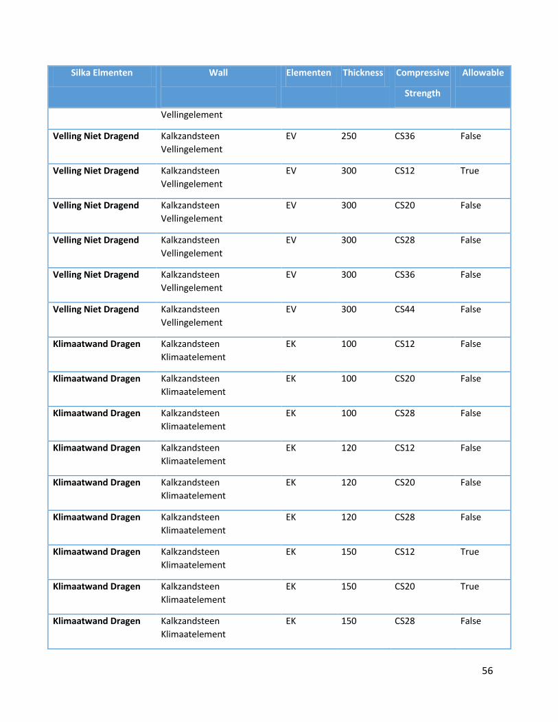
56
Silka Elmenten Wall
Elementen Thickness Compressive
Strength
Allowable
Vellingelement
Velling Niet Dragend Kalkzandsteen
Vellingelement
EV 250 CS36 False
Velling Niet Dragend Kalkzandsteen
Vellingelement
EV 300 CS12 True
Velling Niet Dragend Kalkzandsteen
Vellingelement
EV 300 CS20 False
Velling Niet Dragend Kalkzandsteen
Vellingelement
EV 300 CS28 False
Velling Niet Dragend Kalkzandsteen
Vellingelement
EV 300 CS36 False
Velling Niet Dragend Kalkzandsteen
Vellingelement
EV 300 CS44 False
Klimaatwand Dragen Kalkzandsteen
Klimaatelement
EK 100 CS12 False
Klimaatwand Dragen Kalkzandsteen
Klimaatelement
EK 100 CS20 False
Klimaatwand Dragen Kalkzandsteen
Klimaatelement
EK 100 CS28 False
Klimaatwand Dragen Kalkzandsteen
Klimaatelement
EK 120 CS12 False
Klimaatwand Dragen Kalkzandsteen
Klimaatelement
EK 120 CS20 False
Klimaatwand Dragen Kalkzandsteen
Klimaatelement
EK 120 CS28 False
Klimaatwand Dragen Kalkzandsteen
Klimaatelement
EK 150 CS12 True
Klimaatwand Dragen Kalkzandsteen
Klimaatelement
EK 150 CS20 True
Klimaatwand Dragen Kalkzandsteen
Klimaatelement
EK 150 CS28 False
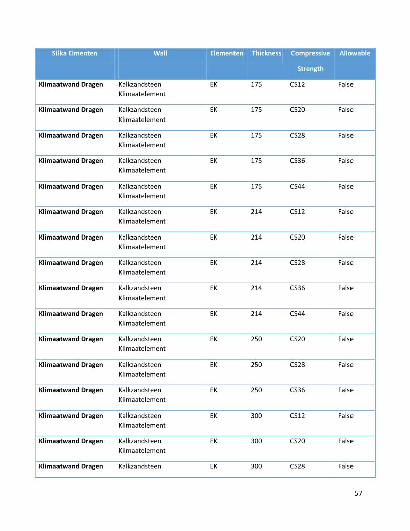
57
Silka Elmenten Wall
Elementen Thickness Compressive
Strength
Allowable
Klimaatwand Dragen Kalkzandsteen
Klimaatelement
EK 175 CS12 False
Klimaatwand Dragen Kalkzandsteen
Klimaatelement
EK 175 CS20 False
Klimaatwand Dragen Kalkzandsteen
Klimaatelement
EK 175 CS28 False
Klimaatwand Dragen Kalkzandsteen
Klimaatelement
EK 175 CS36 False
Klimaatwand Dragen Kalkzandsteen
Klimaatelement
EK 175 CS44 False
Klimaatwand Dragen Kalkzandsteen
Klimaatelement
EK 214 CS12 False
Klimaatwand Dragen Kalkzandsteen
Klimaatelement
EK 214 CS20 False
Klimaatwand Dragen Kalkzandsteen
Klimaatelement
EK 214 CS28 False
Klimaatwand Dragen Kalkzandsteen
Klimaatelement
EK 214 CS36 False
Klimaatwand Dragen Kalkzandsteen
Klimaatelement
EK 214 CS44 False
Klimaatwand Dragen Kalkzandsteen
Klimaatelement
EK 250 CS20 False
Klimaatwand Dragen Kalkzandsteen
Klimaatelement
EK 250 CS28 False
Klimaatwand Dragen Kalkzandsteen
Klimaatelement
EK 250 CS36 False
Klimaatwand Dragen Kalkzandsteen
Klimaatelement
EK 300 CS12 False
Klimaatwand Dragen Kalkzandsteen
Klimaatelement
EK 300 CS20 False
Klimaatwand Dragen Kalkzandsteen EK 300 CS28 False
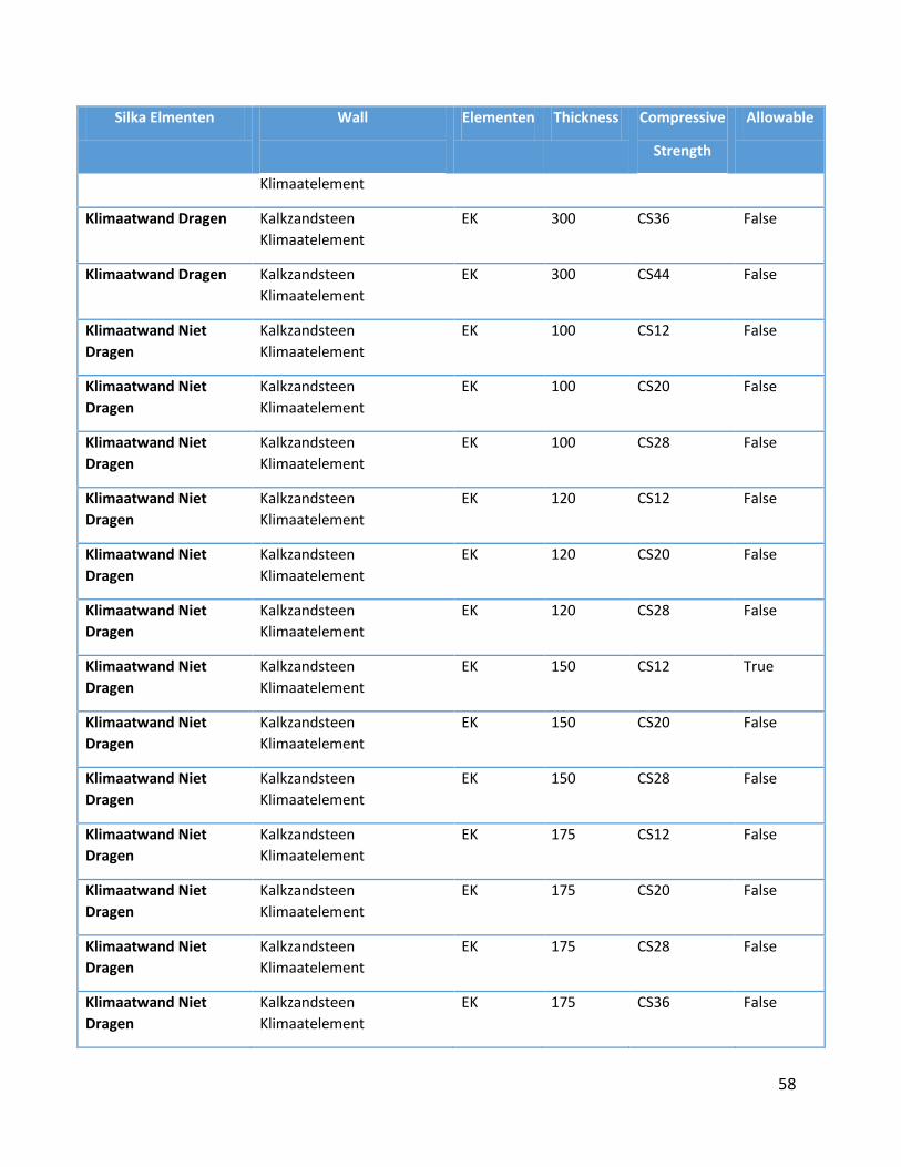
58
Silka Elmenten Wall
Elementen Thickness Compressive
Strength
Allowable
Klimaatelement
Klimaatwand Dragen Kalkzandsteen
Klimaatelement
EK 300 CS36 False
Klimaatwand Dragen Kalkzandsteen
Klimaatelement
EK 300 CS44 False
Klimaatwand Niet
Dragen
Kalkzandsteen
Klimaatelement
EK 100 CS12 False
Klimaatwand Niet
Dragen
Kalkzandsteen
Klimaatelement
EK 100 CS20 False
Klimaatwand Niet
Dragen
Kalkzandsteen
Klimaatelement
EK 100 CS28 False
Klimaatwand Niet
Dragen
Kalkzandsteen
Klimaatelement
EK 120 CS12 False
Klimaatwand Niet
Dragen
Kalkzandsteen
Klimaatelement
EK 120 CS20 False
Klimaatwand Niet
Dragen
Kalkzandsteen
Klimaatelement
EK 120 CS28 False
Klimaatwand Niet
Dragen
Kalkzandsteen
Klimaatelement
EK 150 CS12 True
Klimaatwand Niet
Dragen
Kalkzandsteen
Klimaatelement
EK 150 CS20 False
Klimaatwand Niet
Dragen
Kalkzandsteen
Klimaatelement
EK 150 CS28 False
Klimaatwand Niet
Dragen
Kalkzandsteen
Klimaatelement
EK 175 CS12 False
Klimaatwand Niet
Dragen
Kalkzandsteen
Klimaatelement
EK 175 CS20 False
Klimaatwand Niet
Dragen
Kalkzandsteen
Klimaatelement
EK 175 CS28 False
Klimaatwand Niet
Dragen
Kalkzandsteen
Klimaatelement
EK 175 CS36 False
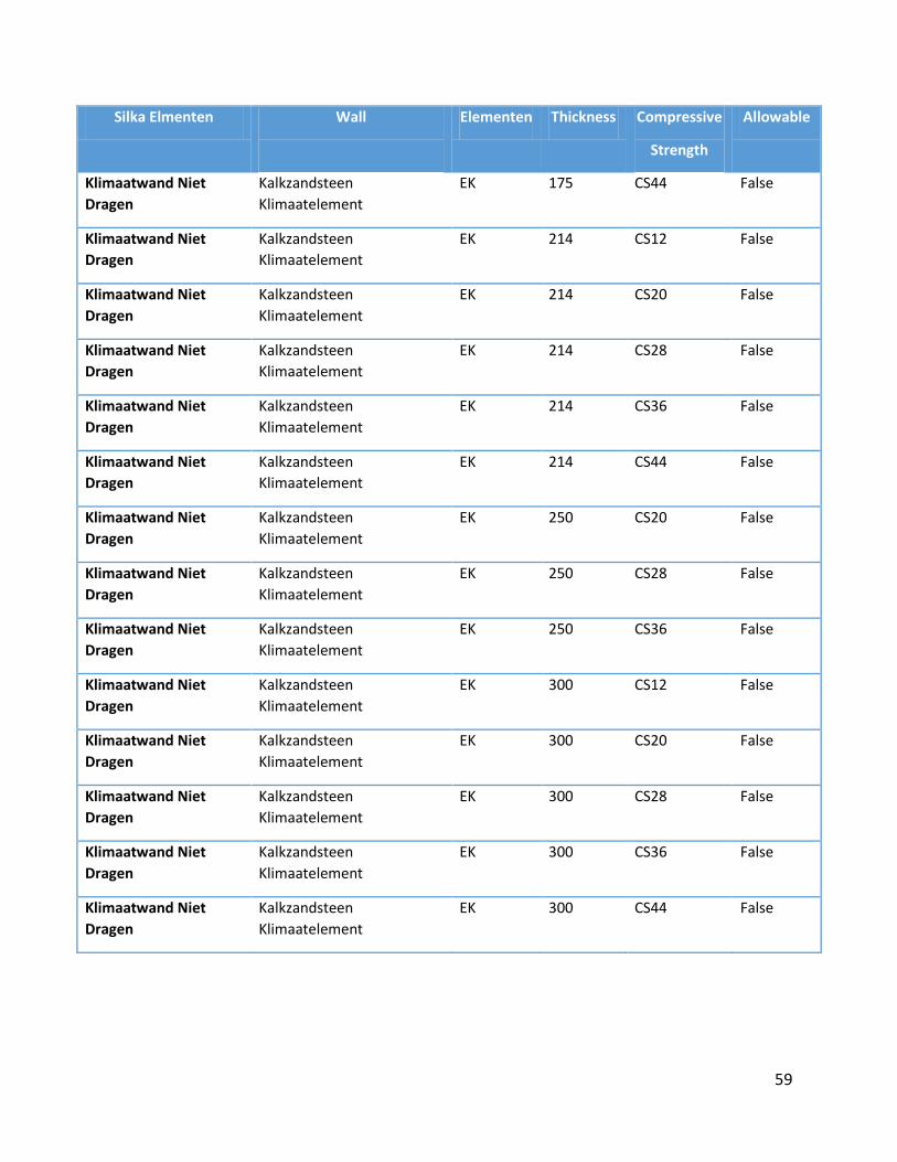
59
Silka Elmenten Wall
Elementen Thickness Compressive
Strength
Allowable
Klimaatwand Niet
Dragen
Kalkzandsteen
Klimaatelement
EK 175 CS44 False
Klimaatwand Niet
Dragen
Kalkzandsteen
Klimaatelement
EK 214 CS12 False
Klimaatwand Niet
Dragen
Kalkzandsteen
Klimaatelement
EK 214 CS20 False
Klimaatwand Niet
Dragen
Kalkzandsteen
Klimaatelement
EK 214 CS28 False
Klimaatwand Niet
Dragen
Kalkzandsteen
Klimaatelement
EK 214 CS36 False
Klimaatwand Niet
Dragen
Kalkzandsteen
Klimaatelement
EK 214 CS44 False
Klimaatwand Niet
Dragen
Kalkzandsteen
Klimaatelement
EK 250 CS20 False
Klimaatwand Niet
Dragen
Kalkzandsteen
Klimaatelement
EK 250 CS28 False
Klimaatwand Niet
Dragen
Kalkzandsteen
Klimaatelement
EK 250 CS36 False
Klimaatwand Niet
Dragen
Kalkzandsteen
Klimaatelement
EK 300 CS12 False
Klimaatwand Niet
Dragen
Kalkzandsteen
Klimaatelement
EK 300 CS20 False
Klimaatwand Niet
Dragen
Kalkzandsteen
Klimaatelement
EK 300 CS28 False
Klimaatwand Niet
Dragen
Kalkzandsteen
Klimaatelement
EK 300 CS36 False
Klimaatwand Niet
Dragen
Kalkzandsteen
Klimaatelement
EK 300 CS44 False

60
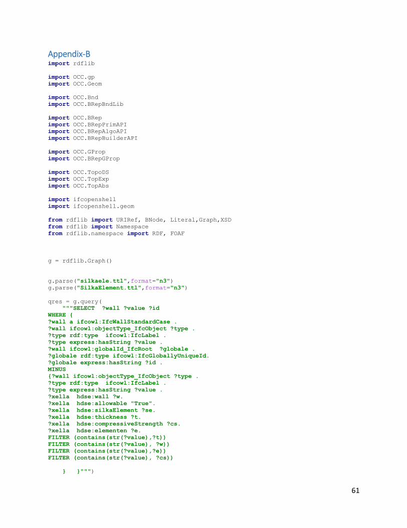
61
Appendix-B import rdflib
import OCC.gp
import OCC.Geom
import OCC.Bnd
import OCC.BRepBndLib
import OCC.BRep
import OCC.BRepPrimAPI
import OCC.BRepAlgoAPI
import OCC.BRepBuilderAPI
import OCC.GProp
import OCC.BRepGProp
import OCC.TopoDS
import OCC.TopExp
import OCC.TopAbs
import ifcopenshell
import ifcopenshell.geom
from rdflib import URIRef, BNode, Literal,Graph,XSD
from rdflib import Namespace
from rdflib.namespace import RDF, FOAF
g = rdflib.Graph()
g.parse("silkaele.ttl",format="n3")
g.parse("SilkaElement.ttl",format="n3")
qres = g.query(
"""SELECT ?wall ?value ?id
WHERE {
?wall a ifcowl:IfcWallStandardCase .
?wall ifcowl:objectType_IfcObject ?type .
?type rdf:type ifcowl:IfcLabel .
?type express:hasString ?value .
?wall ifcowl:globalId_IfcRoot ?globale .
?globale rdf:type ifcowl:IfcGloballyUniqueId.
?globale express:hasString ?id .
MINUS
{?wall ifcowl:objectType_IfcObject ?type .
?type rdf:type ifcowl:IfcLabel .
?type express:hasString ?value .
?xella hdse:wall ?w.
?xella hdse:allowable "True".
?xella hdse:silkaElement ?se.
?xella hdse:thickness ?t.
?xella hdse:compressiveStrength ?cs.
?xella hdse:elementen ?e.
FILTER (contains(str(?value),?t))
FILTER (contains(str(?value), ?w))
FILTER (contains(str(?value),?e))
FILTER (contains(str(?value), ?cs))
} }""")
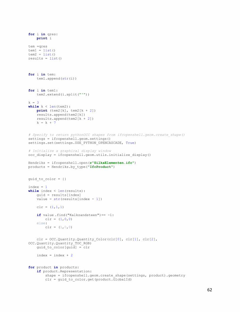
62
for i in qres:
print i
tem =qres
tem1 = list()
tem2 = list()
results = list()
for i in tem:
tem1.append(str(i))
for i in tem1:
tem2.extend(i.split("'"))
k = 3
while k < len(tem2):
print (tem2[k], tem2[k + 2])
results.append(tem2[k])
results.append(tem2[k + 2])
k = k + 7
# Specify to return pythonOCC shapes from ifcopenshell.geom.create_shape()
settings = ifcopenshell.geom.settings()
settings.set(settings.USE_PYTHON_OPENCASCADE, True)
# Initialize a graphical display window
occ_display = ifcopenshell.geom.utils.initialize_display()
Hendriks = ifcopenshell.open(r"SilkaElementen.ifc")
products = Hendriks.by_type("IfcProduct")
guid_to_color = {}
index = 1
while index < len(results):
guid = results[index]
value = str(results[index - 1])
clr = (1,1,1)
if value .find("Kalkzandsteen")== -1: clr = (1,0,0)
else:
clr = (1,0,0)
clr = OCC.Quantity.Quantity_Color(clr[0], clr[1], clr[2],
OCC.Quantity.Quantity_TOC_RGB)
guid_to_color[guid] = clr
index = index + 2
for product in products:
if product.Representation:
shape = ifcopenshell.geom.create_shape(settings, product).geometry
clr = guid_to_color.get(product.GlobalId)

63
display_shape = ifcopenshell.geom.utils.display_shape(shape, clr)
if not clr:
ifcopenshell.geom.utils.set_shape_transparency(display_shape, 0.8)
occ_display.FitAll()
ifcopenshell.geom.utils.main_loop()

64
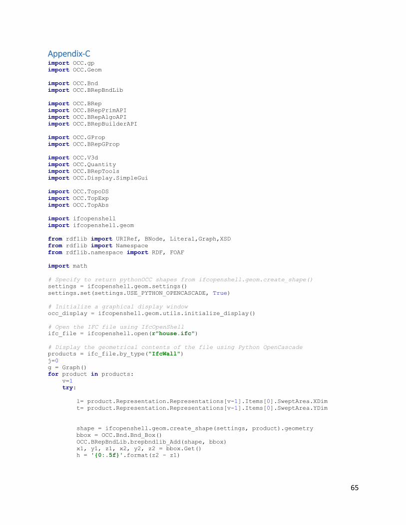
65
Appendix-C import OCC.gp
import OCC.Geom
import OCC.Bnd
import OCC.BRepBndLib
import OCC.BRep
import OCC.BRepPrimAPI
import OCC.BRepAlgoAPI
import OCC.BRepBuilderAPI
import OCC.GProp
import OCC.BRepGProp
import OCC.V3d
import OCC.Quantity
import OCC.BRepTools
import OCC.Display.SimpleGui
import OCC.TopoDS
import OCC.TopExp
import OCC.TopAbs
import ifcopenshell
import ifcopenshell.geom
from rdflib import URIRef, BNode, Literal,Graph,XSD
from rdflib import Namespace
from rdflib.namespace import RDF, FOAF
import math
# Specify to return pythonOCC shapes from ifcopenshell.geom.create_shape()
settings = ifcopenshell.geom.settings()
settings.set(settings.USE_PYTHON_OPENCASCADE, True)
# Initialize a graphical display window
occ_display = ifcopenshell.geom.utils.initialize_display()
# Open the IFC file using IfcOpenShell
ifc_file = ifcopenshell.open(r"house.ifc")
# Display the geometrical contents of the file using Python OpenCascade
products = ifc_file.by_type("IfcWall")
j=0
g = Graph()
for product in products:
v=1
try:
l= product.Representation.Representations[v-1].Items[0].SweptArea.XDim
t= product.Representation.Representations[v-1].Items[0].SweptArea.YDim
shape = ifcopenshell.geom.create_shape(settings, product).geometry
bbox = OCC.Bnd.Bnd_Box()
OCC.BRepBndLib.brepbndlib_Add(shape, bbox)
x1, y1, z1, x2, y2, z2 = bbox.Get()
h = '{0:.5f}'.format(z2 - z1)
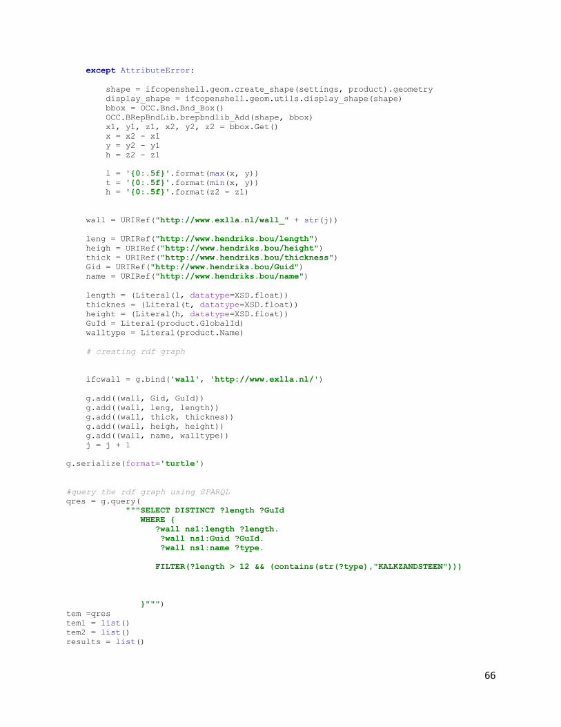
66
except AttributeError:
shape = ifcopenshell.geom.create_shape(settings, product).geometry
display_shape = ifcopenshell.geom.utils.display_shape(shape)
bbox = OCC.Bnd.Bnd_Box()
OCC.BRepBndLib.brepbndlib_Add(shape, bbox)
x1, y1, z1, x2, y2, z2 = bbox.Get()
x = x2 - x1
y = y2 - y1
h = z2 - z1
l = '{0:.5f}'.format(max(x, y))
t = '{0:.5f}'.format(min(x, y))
h = '{0:.5f}'.format(z2 - z1)
wall = URIRef("http://www.exlla.nl/wall_" + str(j))
leng = URIRef("http://www.hendriks.bou/length")
heigh = URIRef("http://www.hendriks.bou/height")
thick = URIRef("http://www.hendriks.bou/thickness")
Gid = URIRef("http://www.hendriks.bou/Guid")
name = URIRef("http://www.hendriks.bou/name")
length = (Literal(l, datatype=XSD.float))
thicknes = (Literal(t, datatype=XSD.float))
height = (Literal(h, datatype=XSD.float))
GuId = Literal(product.GlobalId)
walltype = Literal(product.Name)
# creating rdf graph
ifcwall = g.bind('wall', 'http://www.exlla.nl/')
g.add((wall, Gid, GuId))
g.add((wall, leng, length))
g.add((wall, thick, thicknes))
g.add((wall, heigh, height))
g.add((wall, name, walltype))
j = j + 1
g.serialize(format='turtle')
#query the rdf graph using SPARQL
qres = g.query(
"""SELECT DISTINCT ?length ?GuId
WHERE {
?wall ns1:length ?length.
?wall ns1:Guid ?GuId.
?wall ns1:name ?type.
FILTER(?length > 12 && (contains(str(?type),"KALKZANDSTEEN")))
}""")
tem =qres
tem1 = list()
tem2 = list()
results = list()
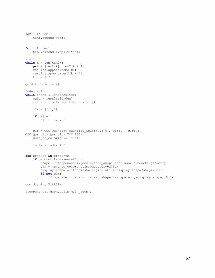
67
for i in tem:
tem1.append(str(i))
for i in tem1:
tem2.extend(i.split("'"))
k = 1
while k < len(tem2):
print (tem2[k], tem2[k + 4])
results.append(tem2[k])
results.append(tem2[k + 4])
k = k + 7
guid_to_color = {}
index = 1
while index < len(results):
guid = results[index]
value = float(results[index - 1])
clr = (1,1,1)
if value:
clr = (1,0,0)
clr = OCC.Quantity.Quantity_Color(clr[0], clr[1], clr[2],
OCC.Quantity.Quantity_TOC_RGB)
guid_to_color[guid] = clr
index = index + 2
for product in products:
if product.Representation:
shape = ifcopenshell.geom.create_shape(settings, product).geometry
clr = guid_to_color.get(product.GlobalId)
display_shape = ifcopenshell.geom.utils.display_shape(shape, clr)
if not clr:
ifcopenshell.geom.utils.set_shape_transparency(display_shape, 0.8)
occ_display.FitAll()
ifcopenshell.geom.utils.main_loop()