Embed Size (px)
Citation preview

AUTOMATED EXTRUSION DIE DESIGN INTEGRATED WITH
SIMULATION OF MATERIAL FLOW
Nikolay Biba1*
, Sergey Stebunov2, Andrey Lishny
2, Alexey Duzhev
2
1Micas Simulation Ltd., 107 Oxford Road, Oxford, OX4 2ER, UK, [email protected] 2QuantorForm Ltd. 115088 P.O. Box 74, Moscow, Russia, [email protected]
*Corresponding Author
Keywords: extrusion, aluminium, simulation, dies, weld, design, profiles
Abstract. After years of intensive development the numerical modelling of extrusion has
reached a certain maturity and practical applicability. An essential requirement for effective
extrusion simulation is the availability of reasonably good quality 3D CAD models of dies
however many die makers still produce their products using 2D drawings and do not have not
full 3D models of them. To bridge the gap between requirements of simulation and
limitations of industrial practice a new automated system of 3D die design has been
developed. This system not only speeds up the creation of 3D models of the dies but also has
an interface to simulation software QForm-Extrusion that provides rapid analyses of the
material flow in newly developed dies and allows improving the design by virtual corrections
before actual manufacturing. The paper presents basic principles of this approach and an
industrial case study that illustrates all stages of such combined die design and simulation
procedure.
Introduction
Our previous works on development and practical implementation of extrusion simulation
have shown that obtaining of accurate results for complex shape thin profiles requires taking
into consideration many parameters of the process. Our numerical model is based on
Lagrange-Euler approach. The simulation starts in Euler domain that represents the space that is
completely filled with the material prior to the start of the process. On the other hand the free end
of the profile is represented by Lagrange model and this part of simulation domain increases its
length beyond the die orifice. The simulation is capable of predicting this undesirable shape
deterioration and finding ways to minimize it. Validation of the model has been performed for
prediction of load, material flow pattern, profile temperature and die deformation using
special model experiments and numerous industrial case studies [1]. Comprehensive analysis
of the program accuracy has also been done within the International Extrusion Benchmark
Tests in 2007, 2009, 2011 and 2013 by means of comparison of the simulation results with
precisely measured experimental parameters.
The next step of development of our simulation model was introducing of mechanical
coupling of material flow with die deformation. As it was shown in our works [2] the
displacement and distortion of tool surfaces in some cases may have significant influence on
the material flow. There are fine inclinations of bearing surface that may vary within just a
few angular minutes and create local zones with choke or relief caused by die deformation.
Though small, such bearing angle variation may have considerable influence on the material
flow patterns. Moreover, due to elastic deformation of the tooling set, a mandrel may move in

a transverse direction that affects the accuracy of the actual profile shape and also
significantly influences the material flow.
Meanwhile when we consider material flow coupled with die deformation we face some
difficult problems. Relative linear displacement of the opposite sides of the bearing may
reach half a millimeter or more that is actually comparable with a profile thickness. When the
opposite bearing sides shift due to elastic die deformation, the tiny finite elements within the
profile inevitably become critically distorted and further use of the initial finite element mesh
in the material flow domain becomes impossible. In our model this problem is solved by
automatic remeshing the simulation domain to provide best mesh quality during iterations in
the coupled simulation when the die and mandrel are flexible [3].
After achieving very accurate predicting of material flow we expected high demand from
the industry for our simulation software. Unfortunately we faced some practical obstacles
preventing wide spread of simulation among die making and extrusion companies. Many die
makers still develop their products using 2D drawings and do not have full 3D models of
them. Moreover not every CAD model of a die can be successfully meshed. Only a sound
solid body with exact fitting of surfaces can be used for mesh generation. The gaps between
adjacent surfaces or overlapping surfaces in a model actually make mesh generation virtually
impossible. In this case the model should be manually repaired using special programs for
cleaning up the geometry that sometimes takes longer time than the simulation itself.
In this situation it is quite natural to make the next step and develop the software tool for
creation and modification of die geometry and combine this software with simulation for
virtual “error free” die design. With this in mind we have developed a system called QForm-
Extrusion Die Designer (QExDD) that automates the die design routine and significantly
speeds up the process of developing new dies. It also automates creation of 3D die models
from existing 2D drawings. This system has been developed as OEM application powered by
SpaceClaim. This QExDD system has a special interface to QForm-Extrusion software for
data exchange in both directions that make joining their work seamless and easy. This system
starts with 2D draft of the profile to which we add contours of pre-chamber, backer opening
and a set of straight lines specifying location and direction of the webs (Fig. 1. a)
Fig. 1. 2D drawing of the profile with additional contours (a) and the model of the die set
after creating it in 3D and transferred to simulation (b).

Case study: Die design development with QExDD system
QExDD is a system of parametric design of extrusion dies for solid and hollow profiles produced
from aluminium alloys. QExDD was developed as OEM application in the environment of CAD
system SpaceClaim belonging to ANSYS. This CAD implements an idea of direct modelling. This
system enables creating, editing or repairing die set geometry. A 3D model of the die set created in
QExDD can be transferred to simulation and virtual extrusion trials through special interface and
finally it can be used by any CAM system for die set machining.
The die is the main element of any tool set so parametric design procedure starts from the
die. To build the die we need an external contour of extruded profile, a pre-chamber contour
and an outer contour of the die cap. Then using a special control panel (Fig. 2a) and the drafts
of the contours (Fig. 2b) in few sequential steps we can specify all parameters and finally get
a 3D model of a die (Fig 2c).
a. b. c.
Fig 2. The control panel for creating a die block (a), 2D set of the contours specifying a die
configuration (b) and a set of 3D solid bodies representing different parts of the die block (c)
The second stage is a mandrel parametric design. It requires an internal contour of an
extruded profile, external contour of the mandrel, a die cap and the set of lines that define
web locations. These lines coincide with middle lines of the webs (Fig. 3b). To speed up the
work several webs may be created concurrently as a group if they have identical shapes and
sizes. After selecting a central web line and typing the parameters of the web design in a
control panel (Fig 3a) we can see a preview of our design (Fig 3c). Similarly we make the
solid model of the backer using its inner and outer contours and proper values of parameters.

a. b. c.
Fig. 3. The control panel for mandrel creation (a), web lines over 2D drawing (b) and the
mandrel block with webs and core as 3D solid bodies (c).
During parametric design QExDD also provides automatic creation of the relief that is
based on using the profile contour and some parameters like relief contour offset and its draft
angle. The program has also a bearing editor for creating bearing length variation. Moreover
the program can create the bearing design automatically. This method is based on some
empiric rules. The bearing length varies according to the profile thickness, the distance to the
geometric die center, size of adjacent porthole and pre-chamber in a specific point. Of course,
bearing configuration created at the stage of design is a preliminary guess but it provides very
good starting point for further bearing optimisation that is based on results of material flow
simulation as shown later in this paper.
All created solid parts are to be merged together forming a die and a mandrel. In the
mandrel all necessary fillets are to be added making smooth conjunctions in a web area.
Finally we get a solid model of the die set as shown on Fig. 4b.
a. b.
Fig. 4. The mandrel with webs and core and the die plate and backer as separate solid bodies
(a); a complete tooling set as a single solid body ready to be for transferred for simulation (b).
Case study: die design improvement by means of simulation
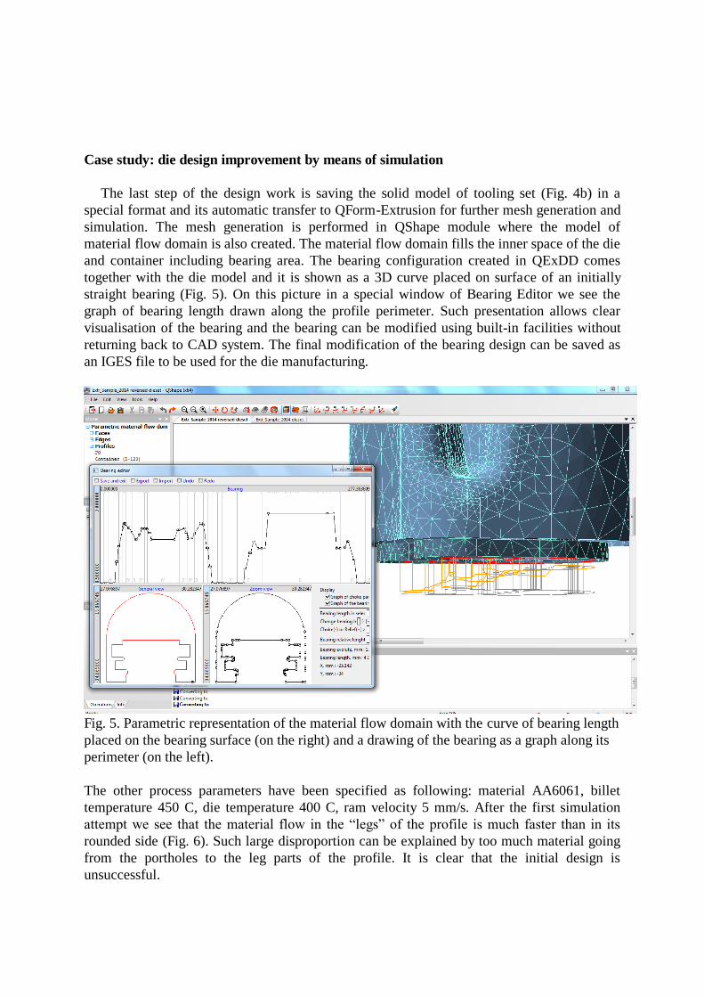
The last step of the design work is saving the solid model of tooling set (Fig. 4b) in a
special format and its automatic transfer to QForm-Extrusion for further mesh generation and
simulation. The mesh generation is performed in QShape module where the model of
material flow domain is also created. The material flow domain fills the inner space of the die
and container including bearing area. The bearing configuration created in QExDD comes
together with the die model and it is shown as a 3D curve placed on surface of an initially
straight bearing (Fig. 5). On this picture in a special window of Bearing Editor we see the
graph of bearing length drawn along the profile perimeter. Such presentation allows clear
visualisation of the bearing and the bearing can be modified using built-in facilities without
returning back to CAD system. The final modification of the bearing design can be saved as
an IGES file to be used for the die manufacturing.
Fig. 5. Parametric representation of the material flow domain with the curve of bearing length
placed on the bearing surface (on the right) and a drawing of the bearing as a graph along its
perimeter (on the left).
The other process parameters have been specified as following: material AA6061, billet
temperature 450 C, die temperature 400 C, ram velocity 5 mm/s. After the first simulation
attempt we see that the material flow in the “legs” of the profile is much faster than in its
rounded side (Fig. 6). Such large disproportion can be explained by too much material going
from the portholes to the leg parts of the profile. It is clear that the initial design is
unsuccessful.

Fig. 6. The material flow obtained with the initial porthole design. The location of portholes
over the profile and seam welds location are shown in boxes in lower left corner.
Let us change the location of the webs to reduce the amount of the material going to these
legs areas. We just need to rotate the lines that specify the location of the webs as shown on
Fig. 7a. Then by re-playing all subsequent steps of the design process we get solid model of
the die set with opposite orientation of the webs (Fig. 7b) and respectively its finite element
model of material flow domain (Fig. 7c).
a. b. c.
Fig. 7. Second variant of the web design presented as a drawing (a), as a complete 3D model
(b) and as a material flow domain with the mesh ready for simulation (c).
After the simulation of this second design variant we have got more balanced material
flow as shown on Fig. 8. Even though the legs of the profile still go faster than its rounded
side now such velocity variation can be eliminated by proper modification of the bearing. As
we see from the drawing of the bearing there is no way to increase the bearing length in the
legs area because it is already long enough and its further elongation will not be effective. A
more effective method is to apply a choke to these areas and this modification has been
implemented on outer surfaces of the legs where it is easier to make (Fig. 9a).

a. b. c.
Fig. 8. Second variant of porthole design: the portholes placement over the profile (a), seam
welds locations (b) and material flow pattern and velocity distribution (c).
a. b.
Fig. 9. Bearing design as it was generated by QExDD but with choke angle applied to the legs
area within red boxes (a) and modified bearing design after the third simulation attempt (b)
a. b. c.
Fig. 10. The material flow after implementing of choke in the legs area as a third attempt of
simulation: beginning of material flow (a) and extending of the profile (b); forth simulation
variant with bearing design as on Fig. 9b (c).
Running the simulation with this modified bearing design we immediately see the effect. At
the beginning of simulation the legs and the rounded part of the profile flow with the same
speed while the inner profile web goes slightly faster (Fig. 10a). To be sure that the design is

really effective we proceeded with the simulation for a longer length and found that the
profile has a slight bend towards the legs (Fig. 10b). That is why one more tuning of the
baring has been done as shown on Fig. 9b in the area highlighted by blue box. Then finally the
material flow has become straight that is clearly seen even with extended profile length (Fig.
10c). It is important to notice that all simulation has been done in coupled mode that means
that the material flow has been simulated concurrently with the deformation of the die and the
die deflection. The axial displacement of the die is shown on Fig. 11a while Fig. 11b presents
the bearing area with distribution of the angle due to its inclination. The distribution of the
effective stress in the die crosscut is shown on Fig. 11c.
a. b. c.
Fig. 11. The axial displacement distribution on the die (a), bearing inclination due to
deformation (b) and effective stress distribution in the die (c)
Conclusions
1. Practical implementation of extrusion simulation has shown that it provides good
accuracy of the results in terms of material flow, load, temperature and die stress.
2. The lack of good quality 3D die models prevents widespread implementation of
simulation software for the needs of die making.
3. To speed up 3D die design and bridge the gap to simulation a special software system
QExDD has been developed.
4. The effectiveness of the method of automated die design combined with simulation
has been illustrated by an industrial case of hollow profile with massive legs.
5. In four iterations the die has been created and successfully modified to provide perfect
straight material flow.
References
[1] S. Stebunov, A. Lishnij, N. Biba, Development and industrial verification of QForm-
Extrusion program for simulation profile extrusion in Proceeding of International Conference
on Extrusion and Benchmark, Dortmund, Germany, 2009, pp. 41-42.
[2] S. Stebunov, N. Biba, A. Vlasov, A. Maximov, Thermally and Mechanically Coupled
Simulation of Metal Forming Processes in Proceedings of the 10th International Conference
on Technology of Plasticity, Aachen, Germany, 2011, pp 171-175.
[3] N. Biba, S. Stebunov, A. Lishnij, Simulation of material flow coupled with die analysis in
complex shape extrusion, Key Engineering Materials, Vol. 585 (2014), pp. 85-92.