Embed Size (px)
Citation preview
AutoFocus FrameworkDocumentation
Pedro NevesGraca GasparLuıs Morgado
DI–FCUL TR–09–1
January 30, 2009
Departamento de InformaticaFaculdade de Ciencias da Universidade de Lisboa
Campo Grande, 1749–016 LisboaPortugal
Technical reports are available at http://www.di.fc.ul.pt/tech-reports. Thefiles are stored in PDF, with the report number as filename. Alternatively, reportsare available by post from the above address.

AutoFocus Framework Documentation
Pedro NevesLabMAg
Departamento de InformaticaUniversidade de Lisboa
Portugal
Graca GasparLabMAg
Departamento de InformaticaUniversidade de Lisboa
Portugal
Luıs MorgadoLabMAg
Instituto Superior de Engenharia de LisboaPortugal
January 30, 2009

Resumo
Esta a ser desenvolvido, na unidade de investigacao LabMAg, o projecto “Auto-
Focus: Adaptive Self-Improving Multi-Agent Systems”. O projecto AutoFocus tem
como objectivo a implementacao de sistemas multi-agente baseados em entidades
autonomicas capazes de comportamentos auto-optimizados e adaptativos.
A nocao de computacao autonomica, tal como outras nocoes que tambem im-
plicam computacao pro-activa, baseia-se em entidades autonomas que agem activa-
mente no sentido de alcancar os seus objectivos e que tem a capacidade de se adaptar
dinamicamente a mudancas no seu ambiente, restringidas por limites de tempo e de
recursos. Na abordagem do projecto AutoFocus essa adaptacao a mudanca, assim
como a regulacao das capacidades dos agentes, e resultante da combinacao de as-
pectos cognitivos com aspectos de base emocional. O modelo de agente subjacente
ao projecto AutoFocus e o Modelo de Agente de Fluxo.
Este relatorio pretende introduzir a plataforma de implementacao para o Modelo
de Agente de Fluxo. Pretende-se com esta plataforma disponibilizar uma ferramenta
que permita a rapida implementacao de agentes baseados neste modelo bem como
a sua monitorizacao.
PALAVRAS-CHAVE:
inteligencia artificial, agentes inteligentes, modelo cognitivo, modelo de emocao,
plataforma de experimentacao
i

Abstract
The work presented in this document is part of the project “AutoFocus: Adaptive
Self-Improving Multi-Agent Systems” that is being developed at the research unit
LabMAg, which objective is the implementation of multi-agent systems based on
autonomous entities capable of self-optimized and adaptive behaviors.
The notion of autonomic computation, like other notions that also imply pro-
active computation, is based on autonomous entities that actively work to achieve
their objectives and have the ability to dynamically adjust to changes in their en-
vironment, constrained by time and resource limits. In the approach used by the
AutoFocus project, that adaptation to change and the regulation of the agent’s ca-
pabilities, result from the combination of cognitive aspects with emotional based
aspects. The agent model defined and used by the AutoFocus project is the Agent
Flow Model.
The task that corresponded to the work presented in this document was to
develop a platform for the Agent Flow Model. It was intended, with this platform,
to provide a tool that enables the rapid deployment and monitoring of agents based
on this model.
The developed work consisted in the analysis and design, oriented to objects,
implementation and testing of components of this platform.
KEYWORDS:
artificial intelligence, intelligent agents, cognitive model, emotion model,
experimentation platform
iii


Contents
List of Figures viii
1 Introduction 1
1.1 Context . . . . . . . . . . . . . . . . . . . . . . . . . . . . . . . . . . 1
1.2 Objectives . . . . . . . . . . . . . . . . . . . . . . . . . . . . . . . . . 1
2 Supporting Theories 3
2.1 Conceptual Spaces . . . . . . . . . . . . . . . . . . . . . . . . . . . . 3
2.2 The Emotion Model . . . . . . . . . . . . . . . . . . . . . . . . . . . 5
3 The Agent Flow Model 13
3.1 The Cognitive Structure . . . . . . . . . . . . . . . . . . . . . . . . . 14
3.1.1 From movement in the cognitive space to emotional dispositions 18
3.2 The Base Mechanisms . . . . . . . . . . . . . . . . . . . . . . . . . . 19
3.2.1 Emotional Disposition Mechanism . . . . . . . . . . . . . . . . 19
3.2.2 Regulation Mechanisms . . . . . . . . . . . . . . . . . . . . . 20
3.2.3 The Base Mechanisms operational view . . . . . . . . . . . . . 22
3.3 The Memory Mechanisms . . . . . . . . . . . . . . . . . . . . . . . . 23
3.3.1 Autobiographical Emotional Memories . . . . . . . . . . . . . 23
3.3.2 Memory Elements . . . . . . . . . . . . . . . . . . . . . . . . . 24
3.3.3 Integration of the Base and Memory Mechanisms . . . . . . . 25
3.4 The Cognitive Processes . . . . . . . . . . . . . . . . . . . . . . . . . 26
4 Design and Implementation of the AutoFocus Platform 27
4.1 Objectives . . . . . . . . . . . . . . . . . . . . . . . . . . . . . . . . . 27
4.2 General Platform Conception . . . . . . . . . . . . . . . . . . . . . . 28
4.3 Domain Model . . . . . . . . . . . . . . . . . . . . . . . . . . . . . . 30
4.4 The Agent, Environment and AutoFocusGlue Systems . . . . . . . . 33
4.4.1 The Agent System . . . . . . . . . . . . . . . . . . . . . . . . 33
4.4.2 The Environment System . . . . . . . . . . . . . . . . . . . . 35
4.4.3 The AutoFocusGlue System . . . . . . . . . . . . . . . . . . . 36
4.4.4 Messages Definitions . . . . . . . . . . . . . . . . . . . . . . . 40
v
4.5 Design and Implementation of the Agent System . . . . . . . . . . . . 44
4.5.1 The Cognitive Structure Classes Model . . . . . . . . . . . . . 44
4.5.2 The Agent classes model . . . . . . . . . . . . . . . . . . . . . 46
4.5.3 The Base Mechanisms . . . . . . . . . . . . . . . . . . . . . . 49
4.5.4 The Memory Mechanisms . . . . . . . . . . . . . . . . . . . . 57
4.6 The Experiment Program . . . . . . . . . . . . . . . . . . . . . . . . 60
4.6.1 Experiment Configuration . . . . . . . . . . . . . . . . . . . . 62
4.6.2 The Report Maker . . . . . . . . . . . . . . . . . . . . . . . . 68
4.6.3 Graphical representation . . . . . . . . . . . . . . . . . . . . . 69
5 Developing a prototype 70
5.1 Defining the cognitive structure . . . . . . . . . . . . . . . . . . . . . 70
5.2 Implementing the environment . . . . . . . . . . . . . . . . . . . . . . 72
5.3 Implementing the agent . . . . . . . . . . . . . . . . . . . . . . . . . 73
5.4 Monitoring the agent and environment . . . . . . . . . . . . . . . . . 74
5.5 Running the prototype . . . . . . . . . . . . . . . . . . . . . . . . . . 75
6 Prototype and Results 77
6.1 The Tileworld . . . . . . . . . . . . . . . . . . . . . . . . . . . . . . . 77
6.1.1 The Tileworld experiment configuration . . . . . . . . . . . . 78
6.1.2 Graphical representation . . . . . . . . . . . . . . . . . . . . . 79
6.1.3 Results . . . . . . . . . . . . . . . . . . . . . . . . . . . . . . . 81
7 Conclusions 85
Bibliography 86
vi
List of Figures
2.1 The weight dimension. . . . . . . . . . . . . . . . . . . . . . . . . . . 4
2.2 Agent as a dissipative structure. . . . . . . . . . . . . . . . . . . . . . 7
2.3 The relationship between agent and environment. . . . . . . . . . . . 8
2.4 The relationship between patterns of achievement potential and flow
and basic emotions. . . . . . . . . . . . . . . . . . . . . . . . . . . . . 9
2.5 Emergence of emotion. . . . . . . . . . . . . . . . . . . . . . . . . . . 10
2.6 Emotional disposition vector. . . . . . . . . . . . . . . . . . . . . . . 11
2.7 Relationship between the two dimensional space quadrants and the
emotional disposition quality. . . . . . . . . . . . . . . . . . . . . . . 12
3.1 The Agent Flow Model architecture. . . . . . . . . . . . . . . . . . . 13
3.2 Formation of cognitive elements from the agent perception. . . . . . . 15
3.3 Mediators as an interface for concrete action. . . . . . . . . . . . . . . 16
3.4 Cognitive activity periods evolution along time. . . . . . . . . . . . . 16
3.5 The role of a mediator, defining a direction of movement of an obser-
vation as the agent acts to try to attain a motivator. . . . . . . . . . 18
3.6 Movement of an observation toward a motivator in the cognitive space. 19
3.7 The emotional disposition space and an emotional disposition vector. 20
3.8 Attention focus mechanism. . . . . . . . . . . . . . . . . . . . . . . . 21
3.9 Operational view of the presented base mechanisms. . . . . . . . . . . 22
3.10 Memorization. . . . . . . . . . . . . . . . . . . . . . . . . . . . . . . . 24
3.11 Integration of memory in the base mechanisms. . . . . . . . . . . . . 25
4.1 The AutoFocus agent domain model. . . . . . . . . . . . . . . . . . . 30
4.2 The three systems that compose the AutoFocus platform. . . . . . . . 33
4.3 The Agent system states. . . . . . . . . . . . . . . . . . . . . . . . . . 34
4.4 The Environment system states. . . . . . . . . . . . . . . . . . . . . . 35
4.5 The AutoFocusGlue system states. . . . . . . . . . . . . . . . . . . . 37
4.6 The AutoFocusGlue initialization sequence. . . . . . . . . . . . . . . . 37
4.7 The AutoFocusGlue start sequence. . . . . . . . . . . . . . . . . . . . 38
4.8 The AutoFocusGlue step sequence and algorithm. . . . . . . . . . . . 39
4.9 The Cat and Mouse World. . . . . . . . . . . . . . . . . . . . . . . . 42
vii
4.10 A view of the cognitive structure class model. . . . . . . . . . . . . . 44
4.11 The agent interface. . . . . . . . . . . . . . . . . . . . . . . . . . . . . 46
4.12 The default agent structure. . . . . . . . . . . . . . . . . . . . . . . . 47
4.13 The base mechanisms interface. . . . . . . . . . . . . . . . . . . . . . 49
4.14 Functional view of the base mechanisms. . . . . . . . . . . . . . . . . 51
4.15 The emotional disposition mechanism interface. . . . . . . . . . . . . 53
4.16 The affective disposition mechanism interface. . . . . . . . . . . . . . 53
4.17 The temporal focus mechanism interface. . . . . . . . . . . . . . . . . 54
4.18 The attention focus mechanism interface. . . . . . . . . . . . . . . . . 56
4.19 Memory mechanisms. . . . . . . . . . . . . . . . . . . . . . . . . . . . 57
4.20 Memory element. . . . . . . . . . . . . . . . . . . . . . . . . . . . . . 58
4.21 The Experiment Program connection to the Agent and Environment
through the AutoFocusGlue. . . . . . . . . . . . . . . . . . . . . . . . 60
4.22 The Experiment Program components. . . . . . . . . . . . . . . . . . 61
4.23 The Report Maker class model. . . . . . . . . . . . . . . . . . . . . . 68
6.1 The relation between the Tileworld dynamism and the agent and
environment activation rates. . . . . . . . . . . . . . . . . . . . . . . 78
6.2 The Tileworld graphical representation. . . . . . . . . . . . . . . . . . 80
6.3 The corresponding agent attention field representation. . . . . . . . . 80
6.4 The best results obtained for the Tileworld. . . . . . . . . . . . . . . 81
6.5 Tileworld results allowing the attention field to be empty. . . . . . . . 82
6.6 Tileworld results after changing the signal of the α and β parameters. 83
6.7 Tileworld results using different α and β parameters. . . . . . . . . . 84
viii
Chapter 1
Introduction
This initial chapter briefly describes the organization of this document and presents
the main objectives of the AutoFocus project.
1.1 Context
The AutoFocus project main goal is to develop an agent model and architecture
capable of:
(i) creating the necessary support for real time adaptation an learning, according
to the agent’s experience;
(ii) regulating the agent’s internal processes, according to its resources and time
constraints.
For these purposes the Agent Flow Model was developed by Prof. Luıs Morgado
and introduced in his PhD thesis[6] and several published articles (e.g.[7][8]), co-
authored by Prof. Graca Gaspar.
In the Agent Flow Model the regulation of the agent’s internal processes is
achieved through emotion based mechanisms. These mechanisms regulate the amount
of time and resources used by the agent’s cognitive processes and the formation of
internal memories.
1.2 Objectives
Although several Agent Flow Model prototypes already existed, the key features
that compose this model, namely the cognitive structure and the base mechanisms,
had been specifically implemented for each prototype according to the problem ad-
dressed, thus not representing a general solution.
1

Chapter 1. Introduction 2
The AutoFocus platform was idealized to integrate the knowledge gathered from
those prototypes and to provide a general reusable implementation of the key fea-
tures of the Agent Flow Model. More specifically, to build a computational library
to serve as a tool for a rapid deployment and monitoring of agents based in this
model.
The AutoFocus platform presented in this document was mostly developed dur-
ing Pedro Neves’s MSc thesis[9] work and was finished during the following three
months under a research grant from the LabMAg research unit.
Chapter 2
Supporting Theories
This chapter briefly introduces the main notions upon which the agent flow model
and architecture was defined.
2.1 Conceptual Spaces
The cognitive sciences have two objectives: the explanation of the cognitive activity
through theories and the construction of artifacts that can accomplish those activi-
ties. Artificial Intelligence focuses mostly in the last one and for that purpose, there
are two main approaches to represent cognition from a computational point of view,
the symbolic approach and the associationist approach.
The symbolic approach consists, essentially, in symbol manipulation according to
explicit rules, while the associationist approach focuses on the associations among
different kinds of information elements to represent cognition. Though both ap-
proaches have their advantages and disadvantages, neither can perform reasonably
well the task of concept learning, which is closely tied to the notion of similarity,
central to a large number of cognitive processes.
To overcome these difficulties Gardenfors[4] purposes another form of represen-
tation, the conceptual representation, based on geometrical structures, where simi-
larity relations can be modeled in a natural way.
Quality Dimension
The key notion of this new representation is that of quality dimension, whose role is
to build up the domains needed for representing concepts. Some examples of quality
dimensions are temperature, weight or the three ordinary spatial dimensions height,
width and depth. The main function of these dimensions is to represent various
“qualities” of objects. For example, one can judge tones by their pitch, for which
our perception recognizes an ordering from “low” to “high” tones.
The dimensions form the framework used to assign properties to objects and to
3
Chapter 2. Supporting Theories 4
specify relations among them. The coordinates of a point within a conceptual space
represent particular values on each dimension, for example, a particular temperature,
a particular height, and so forth. It is assumed that each of the quality dimensions
is equipped with certain geometrical structures, like an ordering or a metric. For
example the dimension weight, illustrated in figure 2.1[4], is a positive continuous
ordered dimension.
Figure 2.1: The weight dimension.
Certain quality dimensions are integral in the sense that one cannot assign an
object a value on one dimension without giving it a value on the other. Dimensions
that are not integral are considered separable.
A domain is a set of integral dimensions that are separable from all other di-
mensions. The main reason for decomposing a cognitive structure into domains is
the assumption that an object can be assigned certain properties independently of
other properties.
Conceptual Space
A conceptual space is defined as a collection of one or more domains. A point in
space will represent an object or concept depending on the context in which they
are used. While an object refers to a particular artifact, a concept is an idea that
characterizes a set, or category, of objects.
It is possible to take a particular perspective of a concept by giving some domains
particular attention. This is accomplished by assigning different weights to different
domains.
A property is defined with the aid of a single dimension or domain. The main
idea is that a property corresponds to a region (subspace) of the conceptual space.
In contrast, a concept may be based on several separable subspaces. Properties form
a special case of concepts.
Conceptual spaces are static in the sense that they only describe the structure
of representations. This notion of conceptual spaces, as defined by Gardenfors[4],
served as inspiration for the definition of the conceptual structure of the Agent Flow
Model, defined by Luıs Morgado in his PhD thesis[6], that is the background for the
work presented here.
Chapter 2. Supporting Theories 5
2.2 The Emotion Model
The subjective nature of emotions makes them difficult to characterize, so an expla-
nation is in order of what exactly are we talking about and of the context in which
the term emotion is used in this work.
In the following, I will not attempt to present the different perspectives of emo-
tion that exist today but rather I only intend to introduce the ideas behind the
emotion model upon which the Agent Flow Model was defined.
Cognition
From a classic perspective, emotion requires a minimum level of cognition, which
presupposes a brain structure that only some living beings, like humans and other
mammals, have. However, if we consider the perspective defended by Maturana and
Varela[5], cognition can be defined as the “effective action of a living being in its
environment”. This means that cognition is a common property shared by all living
organisms and can be seen in the organisms capacity to execute actions that allow
them to strive, by adapting to their environments ever changing conditions. In this
perspective, simple organisms, like a bacteria or a plant, are capable of cognition
and action.
Biologic Systems and Autopoiese
One of the main characteristics of the living beings is their capacity to continually
recreate themselves. For example, in complex organisms, tissues and organs substi-
tute their own cells in continual cycles, maintaining, at the same time, their integrity
as a whole. This capacity of dynamic self-creation is designated as autopoiese by
Maturana e Varela[5].
In a autopoietic system each component participates in the creation or transfor-
mation of other components of the system, in a network of interdependence, allowing
the system to continuously create itself.
This process begins with the differentiation of the body in relation to the sur-
rounding environment through a dividing structure, such as the cell membrane. It
is this membrane that allows the internal organization of the body, which in turn
generates it. So, we are not dealing with two separated processes, but rather two
distinct aspects of the same phenomenon. The interruption of any of the processes
would lead to the end the organism[5].
Therefore there is a cyclical relationship of feedback in autopoetic systems, where
each component affects the other which, in turn, affects the former. A central feature
of the feedback cycles is the ability to self-regulate, either by maintaining a stable
internal environment, or by the generation of actions of the system, allowing the
Chapter 2. Supporting Theories 6
continuous viability of the global body.
Auto-regulation and Motivation
With the differentiation between the interior and exterior of the body, through the
mechanisms of self-regulation, all variables that define the inner state are indepen-
dent of the ones that define the exterior. This means that autopoetic systems are
autonomous in nature, which translates to pro-active behaviors, motivated by their
self-regulating processes. These behaviors arise from the need to control and main-
tain the organism integrity.
To this end, the mechanisms of self-regulation regularly monitor the environment,
comparing the values observed with benchmarks, triggering the necessary steps to
reduce the difference observed. This difference represents the motivation of the
organism.
The thermodynamic paradox
The fact that living beings are able to create and maintain an organized structure,
away from equilibrium with the environment, is in apparent opposition to the second
law of thermodynamics, according to which, in a closed system, the entropy can only
increase. This means that the nature tends to homogenization, i.e. change occurs
naturally from order to chaos. Instead, living beings have the ability to create order
from chaos, which goes precisely in the opposite direction.
One solution to this problem introduces the concept of dissipative structure.
This structure would be an open system through which energy and matter flows
along and where the internally generated entropy would be sent out of the system
to ensure its continuity. For example, plants and animals absorb energy and matter
of low entropy, in the form of light or food, and export matter of high entropy in
the form of waste.
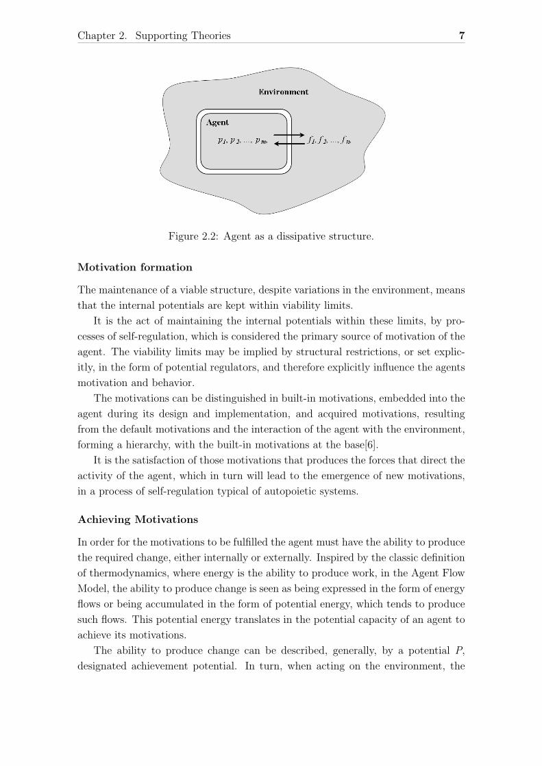
Agent as a dissipative structure
The notion of dissipative structure was chosen by Luıs Morgado[6] as the appropriate
support for modeling an agent that incorporates all three basic characteristic of
biological systems described above: autopoiesis, self-regulation and motivation.
Based on the concept of dissipative structure, an agent is characterized by a set
of internal potentials {p1, p2, ..., pm} and a set of flows {f1, f2, ..., fm}, as depicted in
figure 2.2 taken from [6].
The internal potentials define the internal structure of the agent, varying ac-
cording to the internal activity, which in turn is governed by the maintenance of a
specific internal organization of those same potentials.
Chapter 2. Supporting Theories 7
Figure 2.2: Agent as a dissipative structure.
Motivation formation
The maintenance of a viable structure, despite variations in the environment, means
that the internal potentials are kept within viability limits.
It is the act of maintaining the internal potentials within these limits, by pro-
cesses of self-regulation, which is considered the primary source of motivation of the
agent. The viability limits may be implied by structural restrictions, or set explic-
itly, in the form of potential regulators, and therefore explicitly influence the agents
motivation and behavior.
The motivations can be distinguished in built-in motivations, embedded into the
agent during its design and implementation, and acquired motivations, resulting
from the default motivations and the interaction of the agent with the environment,
forming a hierarchy, with the built-in motivations at the base[6].
It is the satisfaction of those motivations that produces the forces that direct the
activity of the agent, which in turn will lead to the emergence of new motivations,
in a process of self-regulation typical of autopoietic systems.
Achieving Motivations
In order for the motivations to be fulfilled the agent must have the ability to produce
the required change, either internally or externally. Inspired by the classic definition
of thermodynamics, where energy is the ability to produce work, in the Agent Flow
Model, the ability to produce change is seen as being expressed in the form of energy
flows or being accumulated in the form of potential energy, which tends to produce
such flows. This potential energy translates in the potential capacity of an agent to
achieve its motivations.
The ability to produce change can be described, generally, by a potential P,
designated achievement potential. In turn, when acting on the environment, the
Chapter 2. Supporting Theories 8
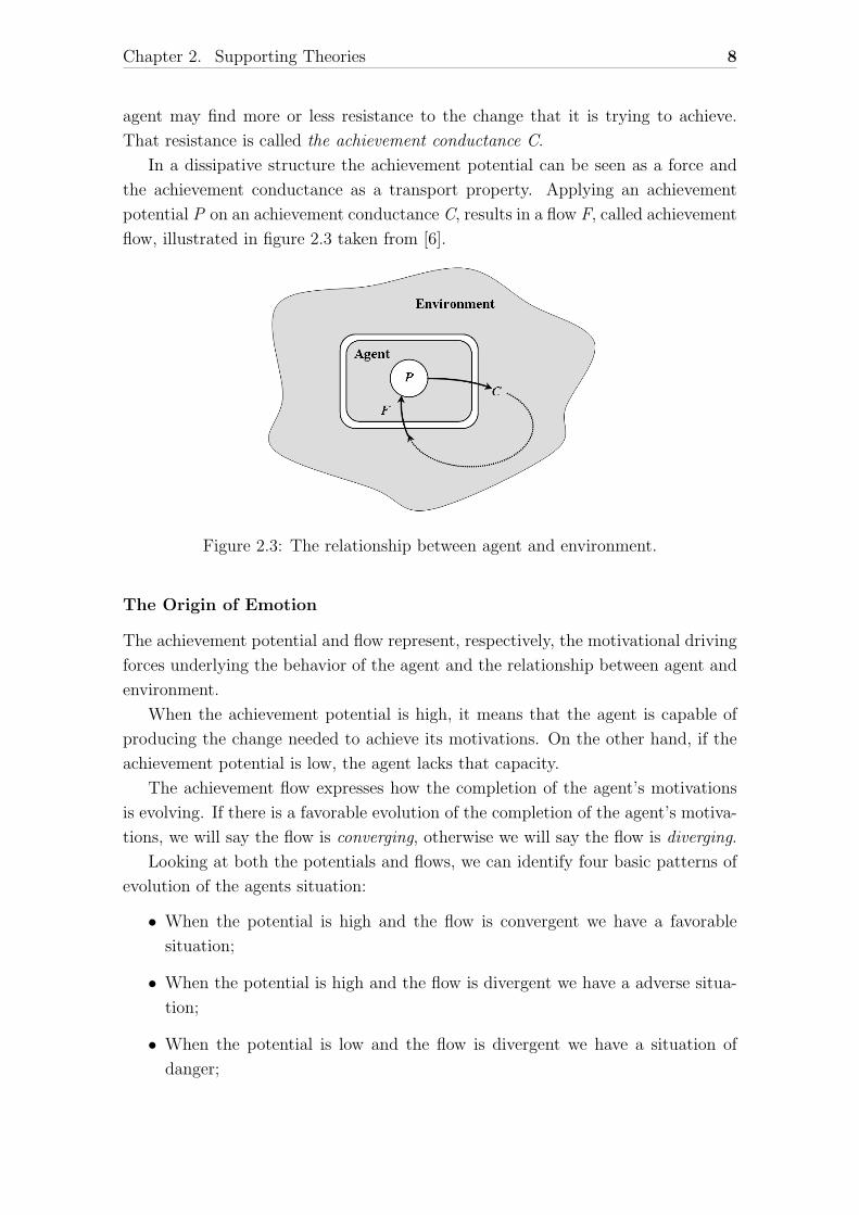
agent may find more or less resistance to the change that it is trying to achieve.
That resistance is called the achievement conductance C.
In a dissipative structure the achievement potential can be seen as a force and
the achievement conductance as a transport property. Applying an achievement
potential P on an achievement conductance C, results in a flow F, called achievement
flow, illustrated in figure 2.3 taken from [6].
Figure 2.3: The relationship between agent and environment.
The Origin of Emotion
The achievement potential and flow represent, respectively, the motivational driving
forces underlying the behavior of the agent and the relationship between agent and
environment.
When the achievement potential is high, it means that the agent is capable of
producing the change needed to achieve its motivations. On the other hand, if the
achievement potential is low, the agent lacks that capacity.
The achievement flow expresses how the completion of the agent’s motivations
is evolving. If there is a favorable evolution of the completion of the agent’s motiva-
tions, we will say the flow is converging, otherwise we will say the flow is diverging.
Looking at both the potentials and flows, we can identify four basic patterns of
evolution of the agents situation:
• When the potential is high and the flow is convergent we have a favorable
situation;
• When the potential is high and the flow is divergent we have a adverse situa-
tion;
• When the potential is low and the flow is divergent we have a situation of
danger;
Chapter 2. Supporting Theories 9
• When the potential is low and the flow convergent we have a situation of
despondency.
These situations do not represent discrete states, but patterns of change involv-
ing both the dynamics of change and the agent’s consequent behavior. This behavior
is also determined by the nature of the agents, but should consist of some action in
compliance with their motivations.
Making the bridge to the biological world, if we consider the four possible situ-
ations, we can identify in the living beings typical behaviors associated with each
one of the situations.
• A favorable situation is associated with behaviors like approaching and enjoy-
ing;
• An adverse situation is associated with behaviors like mobilization and reac-
tion;
• A situation of danger is associated with behaviors like self-protection and
departure;
• A situation of despondency is associated with behaviors like inaction and re-
covery.
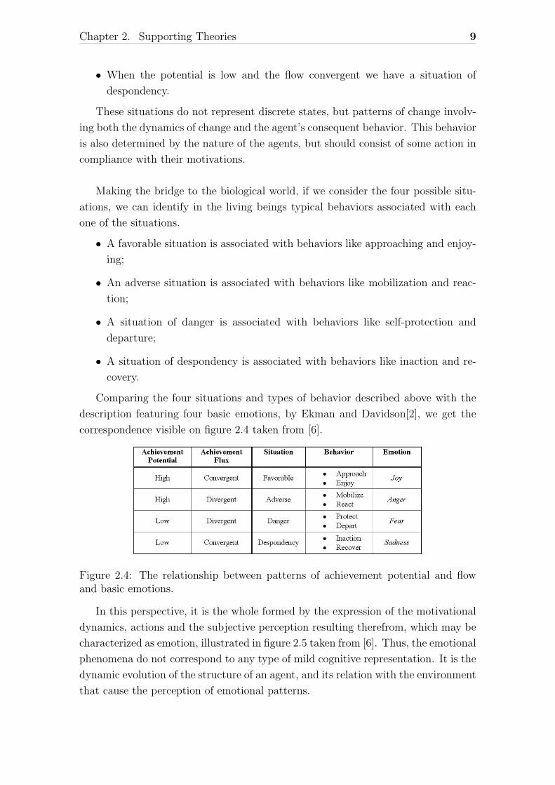
Comparing the four situations and types of behavior described above with the
description featuring four basic emotions, by Ekman and Davidson[2], we get the
correspondence visible on figure 2.4 taken from [6].
Figure 2.4: The relationship between patterns of achievement potential and flowand basic emotions.
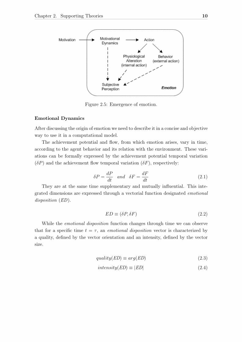
In this perspective, it is the whole formed by the expression of the motivational
dynamics, actions and the subjective perception resulting therefrom, which may be
characterized as emotion, illustrated in figure 2.5 taken from [6]. Thus, the emotional
phenomena do not correspond to any type of mild cognitive representation. It is the
dynamic evolution of the structure of an agent, and its relation with the environment
that cause the perception of emotional patterns.
Chapter 2. Supporting Theories 10
Figure 2.5: Emergence of emotion.
Emotional Dynamics
After discussing the origin of emotion we need to describe it in a concise and objective
way to use it in a computational model.
The achievement potential and flow, from which emotion arises, vary in time,
according to the agent behavior and its relation with the environment. These vari-
ations can be formally expressed by the achievement potential temporal variation
(δP ) and the achievement flow temporal variation (δF ), respectively:
δP =dP
dtand δF =
dF
dt(2.1)
They are at the same time supplementary and mutually influential. This inte-
grated dimensions are expressed through a vectorial function designated emotional
disposition (ED).
ED ≡ (δP, δF ) (2.2)
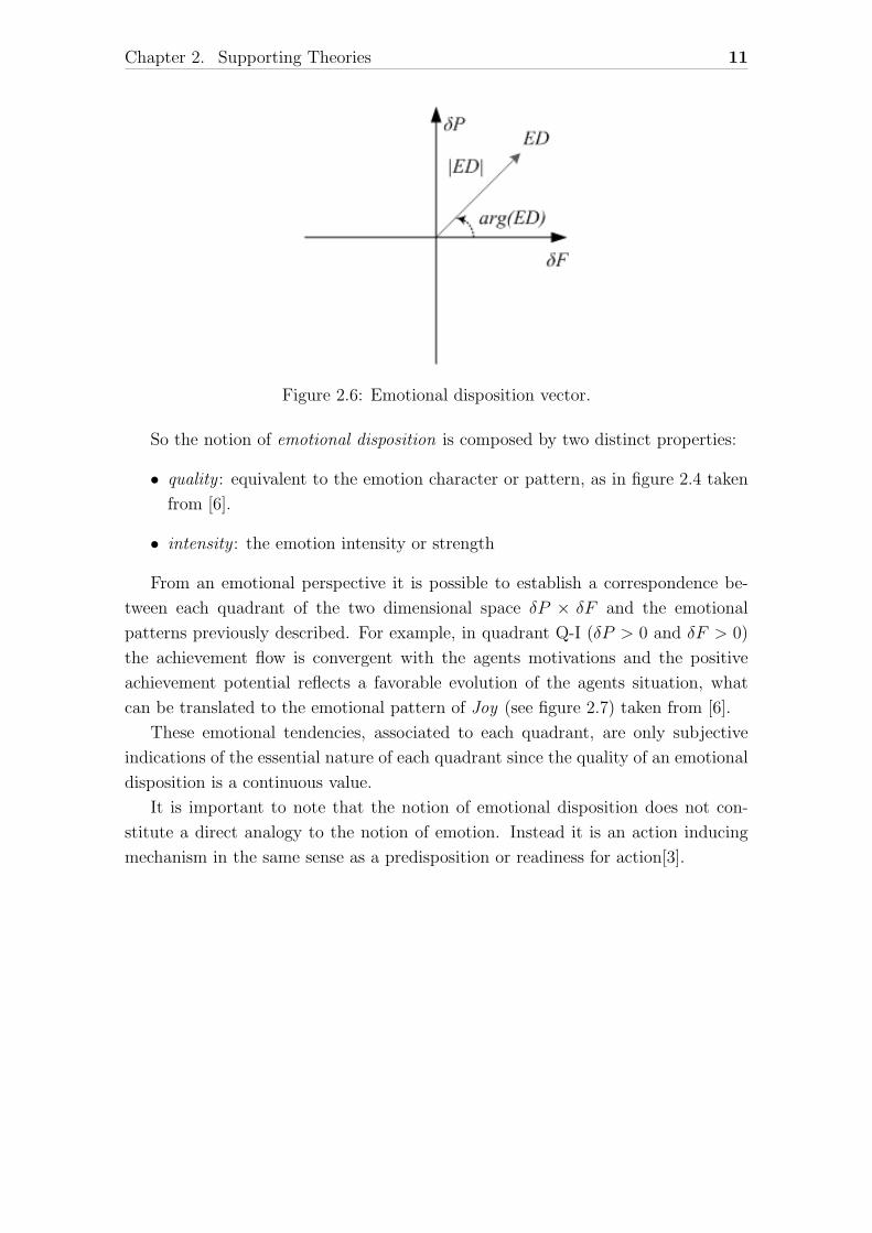
While the emotional disposition function changes through time we can observe
that for a specific time t = τ , an emotional disposition vector is characterized by
a quality, defined by the vector orientation and an intensity, defined by the vector
size.
quality(ED) ≡ arg(ED) (2.3)
intensity(ED) ≡ |ED| (2.4)
Chapter 2. Supporting Theories 11
Figure 2.6: Emotional disposition vector.
So the notion of emotional disposition is composed by two distinct properties:
• quality : equivalent to the emotion character or pattern, as in figure 2.4 taken
from [6].
• intensity : the emotion intensity or strength
From an emotional perspective it is possible to establish a correspondence be-
tween each quadrant of the two dimensional space δP × δF and the emotional
patterns previously described. For example, in quadrant Q-I (δP > 0 and δF > 0)
the achievement flow is convergent with the agents motivations and the positive
achievement potential reflects a favorable evolution of the agents situation, what
can be translated to the emotional pattern of Joy (see figure 2.7) taken from [6].
These emotional tendencies, associated to each quadrant, are only subjective
indications of the essential nature of each quadrant since the quality of an emotional
disposition is a continuous value.
It is important to note that the notion of emotional disposition does not con-
stitute a direct analogy to the notion of emotion. Instead it is an action inducing
mechanism in the same sense as a predisposition or readiness for action[3].
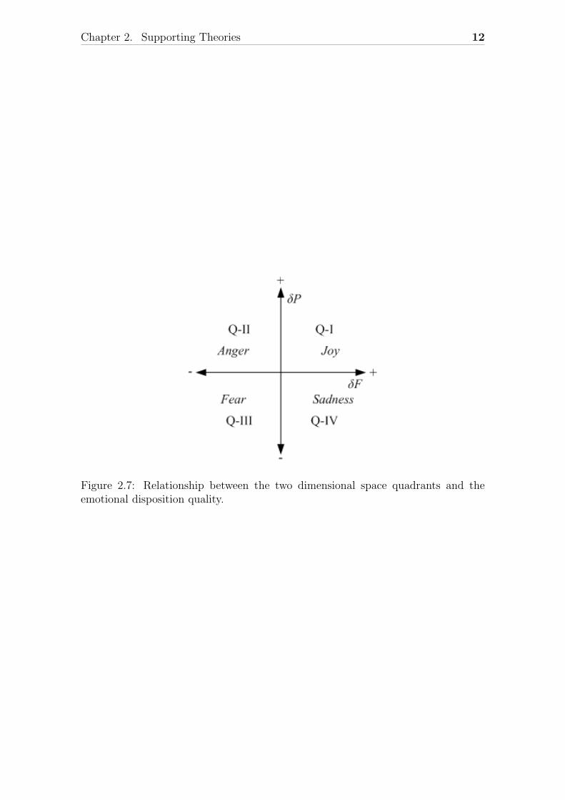
Chapter 2. Supporting Theories 12
Figure 2.7: Relationship between the two dimensional space quadrants and theemotional disposition quality.
Chapter 3
The Agent Flow Model
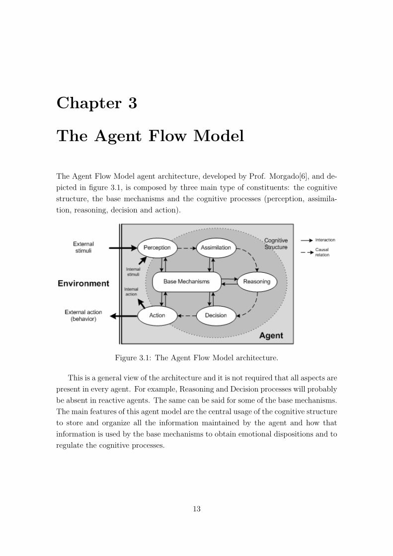
The Agent Flow Model agent architecture, developed by Prof. Morgado[6], and de-
picted in figure 3.1, is composed by three main type of constituents: the cognitive
structure, the base mechanisms and the cognitive processes (perception, assimila-
tion, reasoning, decision and action).
Figure 3.1: The Agent Flow Model architecture.
This is a general view of the architecture and it is not required that all aspects are
present in every agent. For example, Reasoning and Decision processes will probably
be absent in reactive agents. The same can be said for some of the base mechanisms.
The main features of this agent model are the central usage of the cognitive structure
to store and organize all the information maintained by the agent and how that
information is used by the base mechanisms to obtain emotional dispositions and to
regulate the cognitive processes.
13
Chapter 3. The Agent Flow Model 14
3.1 The Cognitive Structure
Under the proposed model, the cognitive structure is composed by all the internal
elements involved in the agents cognitive activity. These elements are modeled as a
composition of internal potentials.
Cognitive Elements
The agent’s potentials result from the interaction between the agent and the en-
vironment, and from the agents own internal activity. In any case, they express
aspects, of the internal and external environment, that correspond to the quality
dimensions (GArdenfors[4]) that the agent is able to discriminate and understand.
Since these potentials form the cognitive structure of the agent, namely in the form
of memories, they are called cognitive potentials.
The cognitive potentials are a composition of two types of signals[6]:
(i) a qualitative signal ϕ(t), that identifies the discriminated dimension;
(ii) a quantitative signal ρ(t), corresponding to the value of the discriminated
dimension.
At a certain time t, a cognitive potential p can be represented by:
p(t) = ρ(t)ϕ(t) (3.1)
Through the aggregation of different cognitive potentials, differentiated by their
corresponding dimension i, we get a cognitive element σ(t), represented by:
σ(t) =K∑i=1
pi(t) (3.2)
where K is the number of aggregated cognitive potentials.
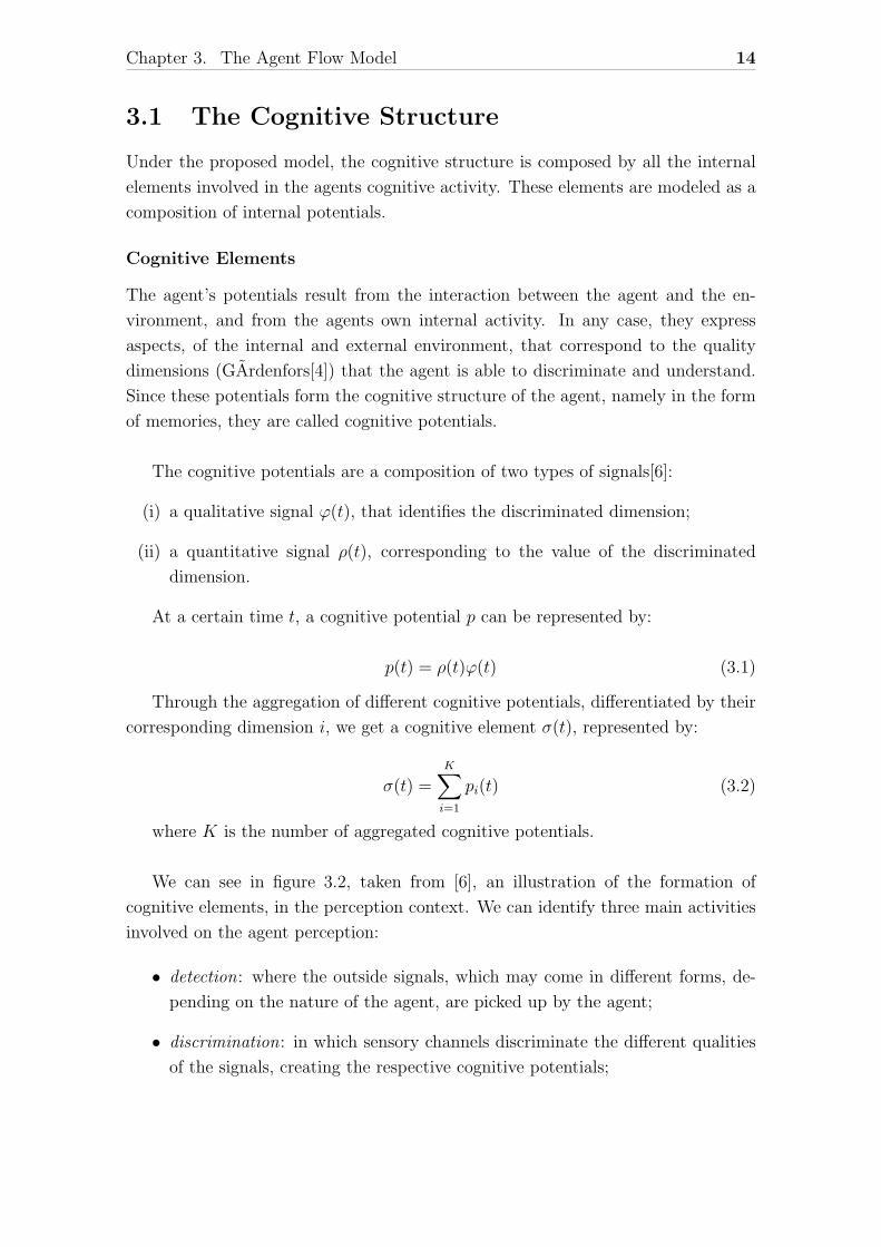
We can see in figure 3.2, taken from [6], an illustration of the formation of
cognitive elements, in the perception context. We can identify three main activities
involved on the agent perception:
• detection: where the outside signals, which may come in different forms, de-
pending on the nature of the agent, are picked up by the agent;
• discrimination: in which sensory channels discriminate the different qualities
of the signals, creating the respective cognitive potentials;
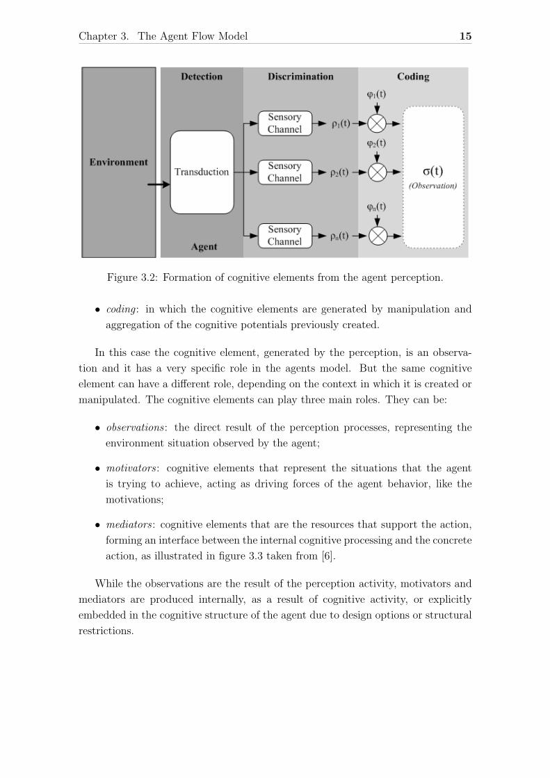
Chapter 3. The Agent Flow Model 15
Figure 3.2: Formation of cognitive elements from the agent perception.
• coding : in which the cognitive elements are generated by manipulation and
aggregation of the cognitive potentials previously created.
In this case the cognitive element, generated by the perception, is an observa-
tion and it has a very specific role in the agents model. But the same cognitive
element can have a different role, depending on the context in which it is created or
manipulated. The cognitive elements can play three main roles. They can be:
• observations : the direct result of the perception processes, representing the
environment situation observed by the agent;
• motivators : cognitive elements that represent the situations that the agent
is trying to achieve, acting as driving forces of the agent behavior, like the
motivations;
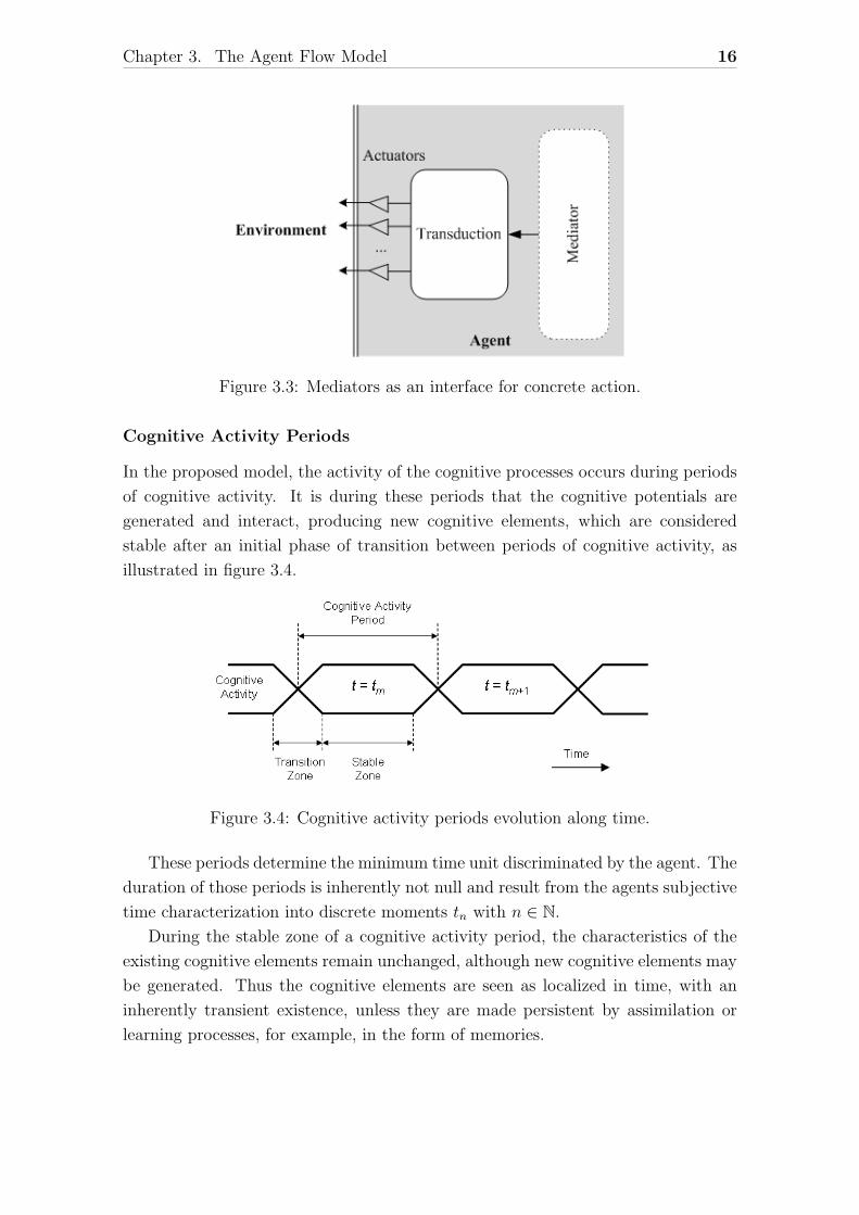
• mediators : cognitive elements that are the resources that support the action,
forming an interface between the internal cognitive processing and the concrete
action, as illustrated in figure 3.3 taken from [6].
While the observations are the result of the perception activity, motivators and
mediators are produced internally, as a result of cognitive activity, or explicitly
embedded in the cognitive structure of the agent due to design options or structural
restrictions.
Chapter 3. The Agent Flow Model 16
Figure 3.3: Mediators as an interface for concrete action.
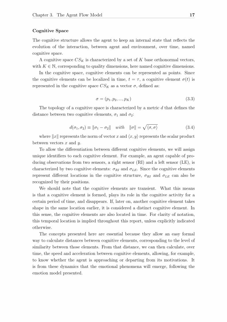
Cognitive Activity Periods
In the proposed model, the activity of the cognitive processes occurs during periods
of cognitive activity. It is during these periods that the cognitive potentials are
generated and interact, producing new cognitive elements, which are considered
stable after an initial phase of transition between periods of cognitive activity, as
illustrated in figure 3.4.
Figure 3.4: Cognitive activity periods evolution along time.
These periods determine the minimum time unit discriminated by the agent. The
duration of those periods is inherently not null and result from the agents subjective
time characterization into discrete moments tn with n ∈ N.
During the stable zone of a cognitive activity period, the characteristics of the
existing cognitive elements remain unchanged, although new cognitive elements may
be generated. Thus the cognitive elements are seen as localized in time, with an
inherently transient existence, unless they are made persistent by assimilation or
learning processes, for example, in the form of memories.
Chapter 3. The Agent Flow Model 17
Cognitive Space
The cognitive structure allows the agent to keep an internal state that reflects the
evolution of the interaction, between agent and environment, over time, named
cognitive space.
A cognitive space CSK is characterized by a set of K base orthonormal vectors,
with K ∈ N, corresponding to quality dimensions, here named cognitive dimensions.
In the cognitive space, cognitive elements can be represented as points. Since
the cognitive elements can be localized in time, t = τ , a cognitive element σ(t) is
represented in the cognitive space CSK as a vector σ, defined as:
σ = (p1, p2, ..., pK) (3.3)
The topology of a cognitive space is characterized by a metric d that defines the
distance between two cognitive elements, σ1 and σ2:
d(σ1, σ2) ≡ ‖σ1 − σ2‖ with ‖σ‖ =√〈σ, σ〉 (3.4)
where ‖x‖ represents the norm of vector x and 〈x, y〉 represents the scalar product
between vectors x and y.
To allow the differentiation between different cognitive elements, we will assign
unique identifiers to each cognitive element. For example, an agent capable of pro-
ducing observations from two sensors, a right sensor (RI) and a left sensor (LE), is
characterized by two cognitive elements: σRI and σLE. Since the cognitive elements
represent different locations in the cognitive structure, σRI and σLE can also be
recognized by their positions.
We should note that the cognitive elements are transient. What this means
is that a cognitive element is formed, plays its role in the cognitive activity for a
certain period of time, and disappears. If, later on, another cognitive element takes
shape in the same location earlier, it is considered a distinct cognitive element. In
this sense, the cognitive elements are also located in time. For clarity of notation,
this temporal location is implied throughout this report, unless explicitly indicated
otherwise.
The concepts presented here are essential because they allow an easy formal
way to calculate distances between cognitive elements, corresponding to the level of
similarity between those elements. From that distance, we can then calculate, over
time, the speed and acceleration between cognitive elements, allowing, for example,
to know whether the agent is approaching or departing from its motivations. It
is from these dynamics that the emotional phenomena will emerge, following the
emotion model presented.
Chapter 3. The Agent Flow Model 18
3.1.1 From movement in the cognitive space to emotionaldispositions
As the agent interacts with the environment, its cognitive elements will change
accordingly, and those changes can be seen as trajectories in the cognitive space.
As we have seen, the behavior of an agent is driven by the relationship between
the agents motivations and the perception of its current situation, expressed by
motivators and observations.
The cognitive activity of the agent is therefore guided by maximizing the flow of
achievement that leads to the reduction of the distance between motivators and ob-
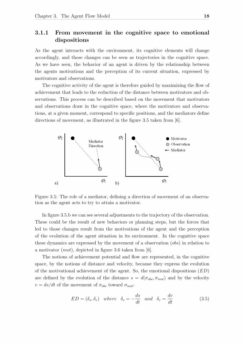
servations. This process can be described based on the movement that motivators
and observations draw in the cognitive space, where the motivators and observa-
tions, at a given moment, correspond to specific positions, and the mediators define
directions of movement, as illustrated in the figure 3.5 taken from [6].
Figure 3.5: The role of a mediator, defining a direction of movement of an observa-tion as the agent acts to try to attain a motivator.
In figure 3.5.b we can see several adjustments to the trajectory of the observation.
These could be the result of new behaviors or planning steps, but the forces that
led to those changes result from the motivations of the agent and the perception
of the evolution of the agent situation in its environment. In the cognitive space
these dynamics are expressed by the movement of a observation (obs) in relation to
a motivator (mot), depicted in figure 3.6 taken from [6].
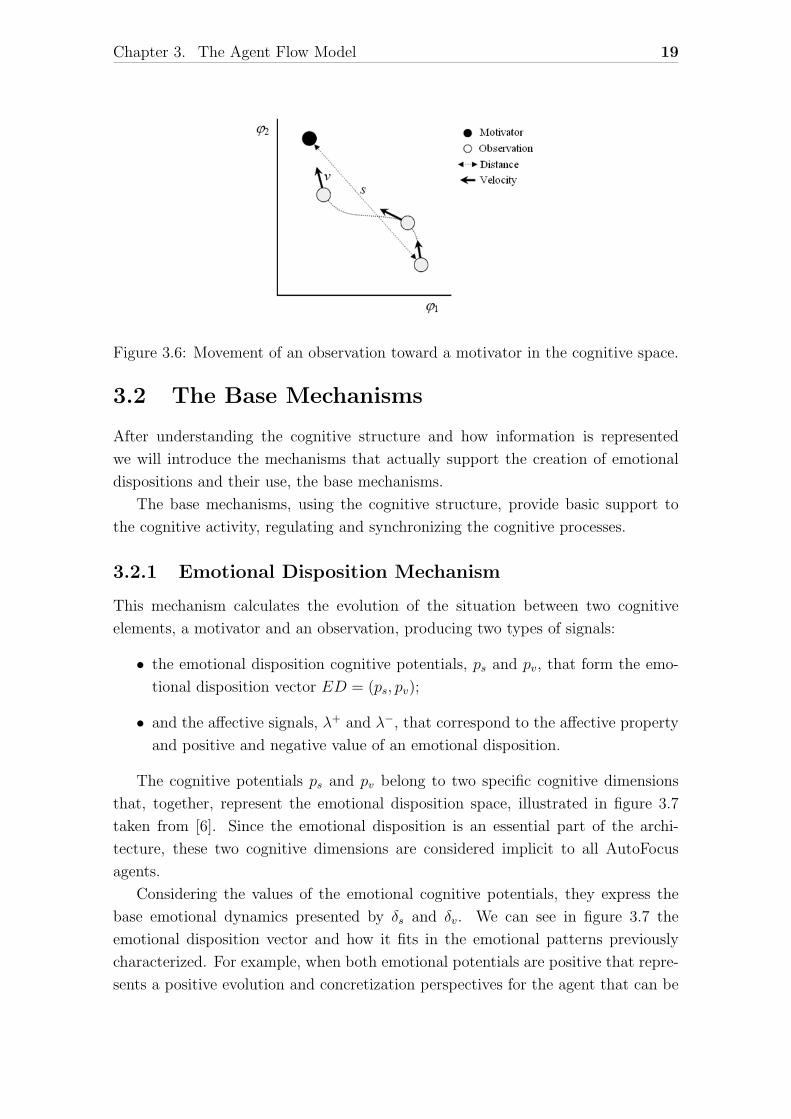
The notions of achievement potential and flow are represented, in the cognitive
space, by the notions of distance and velocity, because they express the evolution
of the motivational achievement of the agent. So, the emotional dispositions (ED)
are defined by the evolution of the distance s = d(σobs, σmot) and by the velocity
v = ds/dt of the movement of σobs toward σmot:
ED = (δs, δv) where δs = −dsdt
and δv =dv
dt(3.5)
Chapter 3. The Agent Flow Model 19
Figure 3.6: Movement of an observation toward a motivator in the cognitive space.
3.2 The Base Mechanisms
After understanding the cognitive structure and how information is represented
we will introduce the mechanisms that actually support the creation of emotional
dispositions and their use, the base mechanisms.
The base mechanisms, using the cognitive structure, provide basic support to
the cognitive activity, regulating and synchronizing the cognitive processes.
3.2.1 Emotional Disposition Mechanism
This mechanism calculates the evolution of the situation between two cognitive
elements, a motivator and an observation, producing two types of signals:
• the emotional disposition cognitive potentials, ps and pv, that form the emo-
tional disposition vector ED = (ps, pv);
• and the affective signals, λ+ and λ−, that correspond to the affective property
and positive and negative value of an emotional disposition.
The cognitive potentials ps and pv belong to two specific cognitive dimensions
that, together, represent the emotional disposition space, illustrated in figure 3.7
taken from [6]. Since the emotional disposition is an essential part of the archi-
tecture, these two cognitive dimensions are considered implicit to all AutoFocus
agents.
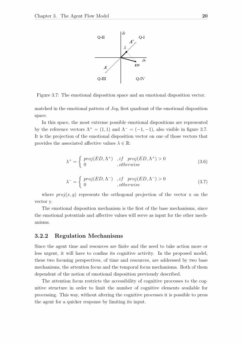
Considering the values of the emotional cognitive potentials, they express the
base emotional dynamics presented by δs and δv. We can see in figure 3.7 the
emotional disposition vector and how it fits in the emotional patterns previously
characterized. For example, when both emotional potentials are positive that repre-
sents a positive evolution and concretization perspectives for the agent that can be
Chapter 3. The Agent Flow Model 20
Figure 3.7: The emotional disposition space and an emotional disposition vector.
matched in the emotional pattern of Joy, first quadrant of the emotional disposition
space.
In this space, the most extreme possible emotional dispositions are represented
by the reference vectors Λ+ = (1, 1) and Λ− = (−1,−1), also visible in figure 3.7.
It is the projection of the emotional disposition vector on one of those vectors that
provides the associated affective values λ ∈ R:
λ+ =
{proj(ED,Λ+) , if proj(ED,Λ+) > 00 , otherwise
(3.6)
λ− =
{proj(ED,Λ−) , if proj(ED,Λ−) > 00 , otherwise
(3.7)
where proj(x, y) represents the orthogonal projection of the vector x on the
vector y.
The emotional disposition mechanism is the first of the base mechanisms, since
the emotional potentials and affective values will serve as input for the other mech-
anisms.
3.2.2 Regulation Mechanisms
Since the agent time and resources are finite and the need to take action more or
less urgent, it will have to confine its cognitive activity. In the proposed model,
these two focusing perspectives, of time and resources, are addressed by two base
mechanisms, the attention focus and the temporal focus mechanisms. Both of them
dependent of the notion of emotional disposition previously described.
The attention focus restricts the accessibility of cognitive processes to the cog-
nitive structure in order to limit the number of cognitive elements available for
processing. This way, without altering the cognitive processes it is possible to press
the agent for a quicker response by limiting its input.
Chapter 3. The Agent Flow Model 21
The temporal focus works through the generation of an indication of the urgency
of the response, restricting the time available for the generation of that response.
An observation and a motivator along with cognitive potentials, ps and pv, that
constitute the associated emotional disposition are integrated to form a more com-
plex cognitive element, σDE. These integrated elements are then presented to the
attention focus mechanism that will decide which ones will be ultimately presented
to the cognitive processes.
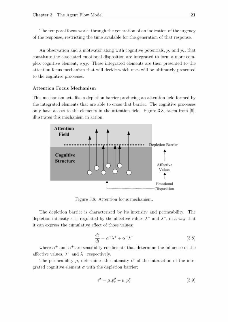
Attention Focus Mechanism
This mechanism acts like a depletion barrier producing an attention field formed by
the integrated elements that are able to cross that barrier. The cognitive processes
only have access to the elements in the attention field. Figure 3.8, taken from [6],
illustrates this mechanism in action.
Figure 3.8: Attention focus mechanism.
The depletion barrier is characterized by its intensity and permeability. The
depletion intensity ε, is regulated by the affective values λ+ and λ−, in a way that
it can express the cumulative effect of those values:
dε
dt= α+λ+ + α−λ− (3.8)
where α+ and α+ are sensibility coefficients that determine the influence of the
affective values, λ+ and λ− respectively.
The permeability µ, determines the intensity εσ of the interaction of the inte-
grated cognitive element σ with the depletion barrier;
εσ = µspσs + µvp
σv (3.9)
Chapter 3. The Agent Flow Model 22
where µs and µv are permeability coefficients that determine the influence of the
emotional potentials pσs and pσv of the element σ. If the interaction intensity εσ is
greater than the depletion barrier intensity ε (εσ > ε), then the integrated cognitive
element σ is included in the attention field.
Temporal Focus Mechanism
The temporal focus mechanism regulates the rate of the cognitive activity. The
temporal base corresponds to a signal pφ with a frequency ωφ which can be used to
determine the cognitive activity period.
The regulation of the frequency ωφ is determined by the affective values λ+ and
λ− using the following equation:
dωφdt
= β+λ+ + β−λ− (3.10)
where β+ and β− are sensibility coefficients that determine the influence of the
affective values, λ+ and λ− respectively.
The variable length of the cognitive activity periods, according to the reference
time signal pφ, allows an indirect regulation of the type and scope of the processing
performed. For example, the perception process can be more detailed or compre-
hensive depending on the time available for it.
The division of the time available for each cognitive process is relegated to the
agent designer.
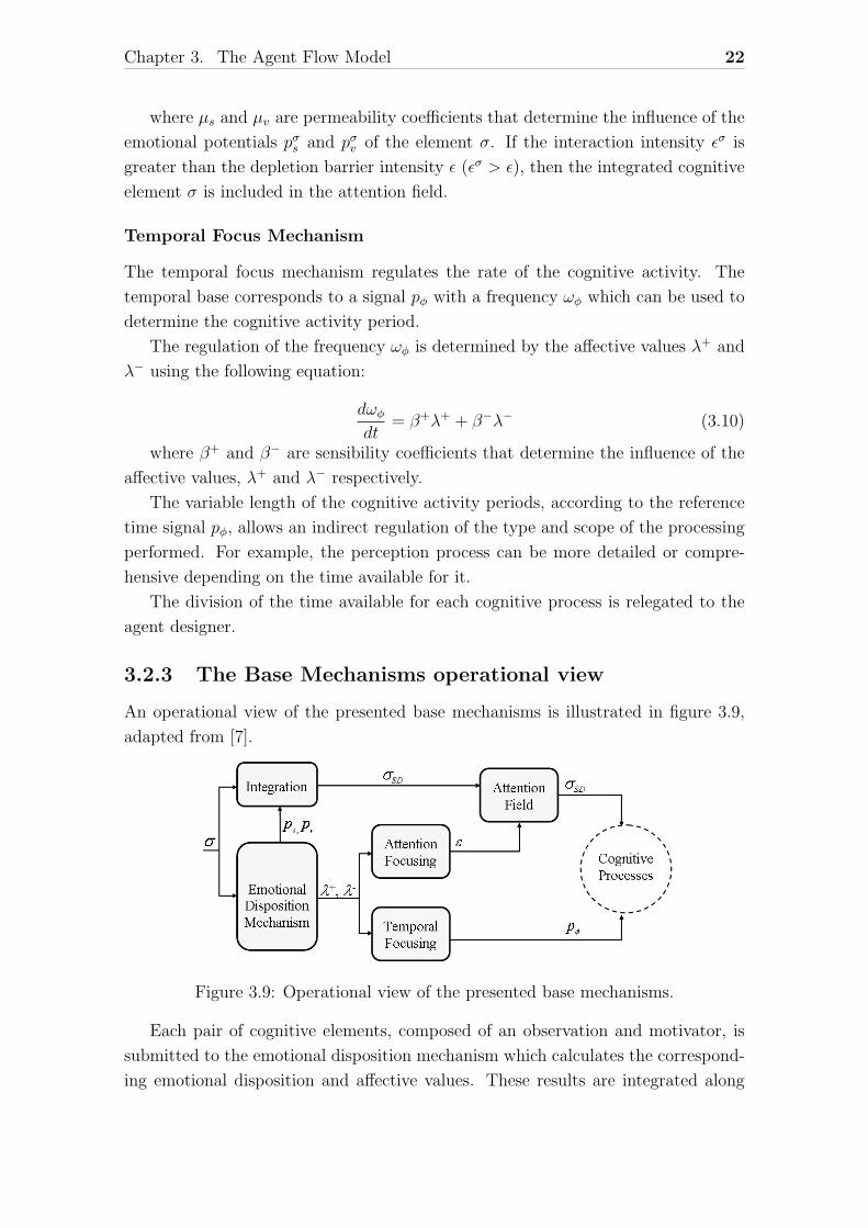
3.2.3 The Base Mechanisms operational view
An operational view of the presented base mechanisms is illustrated in figure 3.9,
adapted from [7].
Figure 3.9: Operational view of the presented base mechanisms.
Each pair of cognitive elements, composed of an observation and motivator, is
submitted to the emotional disposition mechanism which calculates the correspond-
ing emotional disposition and affective values. These results are integrated along
Chapter 3. The Agent Flow Model 23
with the initial cognitive elements to form an integrated cognitive element. After the
integration, the resulting element is submitted to the attention focusing mechanism
where its interaction with the attention barrier will be calculated. If that interac-
tion is greater than the attention barrier value, the element is introduced into the
attention field.
Meanwhile the affective values are used by the attention focusing mechanism
to update the attention field barrier and by the temporal focusing mechanism to
update the activity period length.
In the end, only the significant cognitive elements, present in the attention field,
will be available to the cognitive processes which will have a limited time to compute
in order to calculate the agent’s next action.
3.3 The Memory Mechanisms
In the mechanisms of cognitive regulation presented above, the influence of the emo-
tional dispositions that result from interaction between agent and environment has
been exploited in the short term, that is, only the effect of the current observations
was considered.
When considering a long-term perspective, the key aspect is the ability to record
the experience of the agent through changes that affect the cognitive structure, cre-
ating memories of the experiences of the agent over time. These memories will allow
the agent to anticipate future situations and operate prospectively, contemplating
alternative courses of action, through processes of reasoning.
At the same time, if those memories express the regulating prevailing character
at the time they are formed, they can expand the ability to regulate the focus
mechanisms of the cognitive activity, presented above, through feedback to such
mechanisms. Thus, the regulation of cognitive phenomena can gain an extended
temporal scope.
3.3.1 Autobiographical Emotional Memories
As the cognitive elements evolve over time, they describe trajectories in the cogni-
tive space that reflect the experiences occurred. These paths may or may not be
assimilated in the cognitive structure.
On the other hand, in agents with cognitive processes able to alter their cognitive
structure, the paths drawn by the cognitive elements over time can be assimilated,
forming autobiographical memories. The autobiographical nature of these memories
results from reflecting a temporal sequence rather than just a cluster of memories
without any relationship between them.
Chapter 3. The Agent Flow Model 24
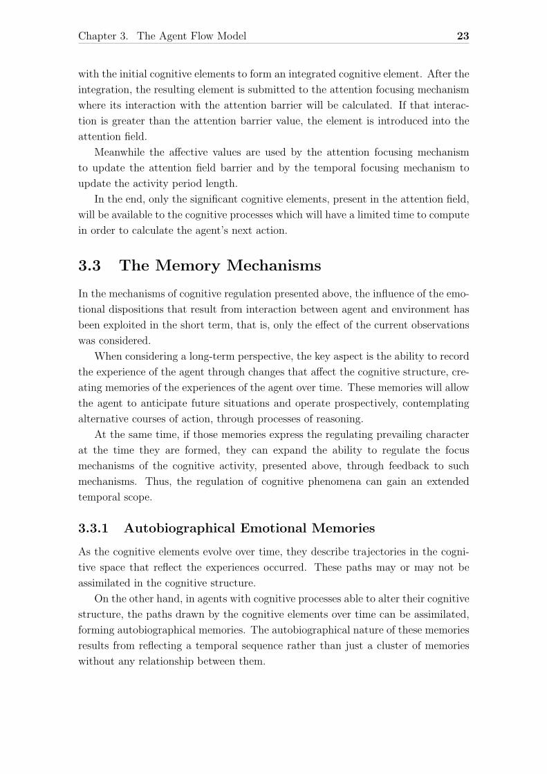
Underlying the formation of these memories are clusters of cognitive elements,
which result from the integration mechanisms. These cognitive elements have an
integrated emotional disposition, leading to the formation of memories of emotional
dispositions, which may be related to what other authors describe as emotional
memories[1]. Figure 3.10 illustrates the relationship between the mechanisms in-
volved in the formation of emotional memories.
Figure 3.10: Memorization.
The emotional potentials, ps and pv, produced by the emotional disposition mech-
anism are integrated with each pair of cognitive elements, producing the σed cog-
nitive elements, which are assimilated in the cognitive structure by the memory
mechanisms.
At the same time, the contents of the emotional dispositions associated with
the recalled memorized elements (the potentials pRs and pRv shown in figure 3.10)
are redirected to the emotional disposition mechanism. Since these mechanisms are
the basis of the regulation of the cognitive activity, the effect is the adaptation of
that activity, predisposing the agent to handle future situations similarly to the ones
recalled.
3.3.2 Memory Elements
To support the representation of the memory elements their time reference must also
be represented in the cognitive space. For this purpose the memory mechanisms pro-
duces a temporal reference signal φv(x) whose spatial frequency varies continuously
and monotonously over time. This signal is used to modulate each cognitive element
σ(t), producing a cognitive element σ(t, x), which can be incorporated into memory,
or only be used to interact with that memory:
σ(t, x) ≡ σ(t)φv(t) (3.11)
In the cognitive space, this new representation of a cognitive element is related
to the previous definition (3.3) as follows:
Chapter 3. The Agent Flow Model 25
σ ≡ (ρ1, ρ2, ..., ρk)ρv (3.12)
where the coefficient ρv ∈ C expresses the intensity and frequency of the signal
v of φv(x) in a given time t = τ . This expression makes it clear that time is not
represented only as one more quality dimension. Instead, the passing of time has a
modulating effect on the representation of each quality dimension.
A cognitive element σ, that interacts with a memory field, activates multiple
memory elements (memories). Given a memory element σM , previously assimilated,
its activation produces a recalled memory element σR, formed as follows:
σR = η(σ.σM)σM (3.13)
where η is the interaction gain between cognitive elements. The recalled memory
elements are modulated images of the original memory elements, whose intensity de-
pends on the similarity (expressed by the interaction gain) between the stimulating
cognitive element and the memory elements. Thus, a memory field acts as a as-
sociative memory in which the cognitive elements are activated by qualitative and
temporal contact.
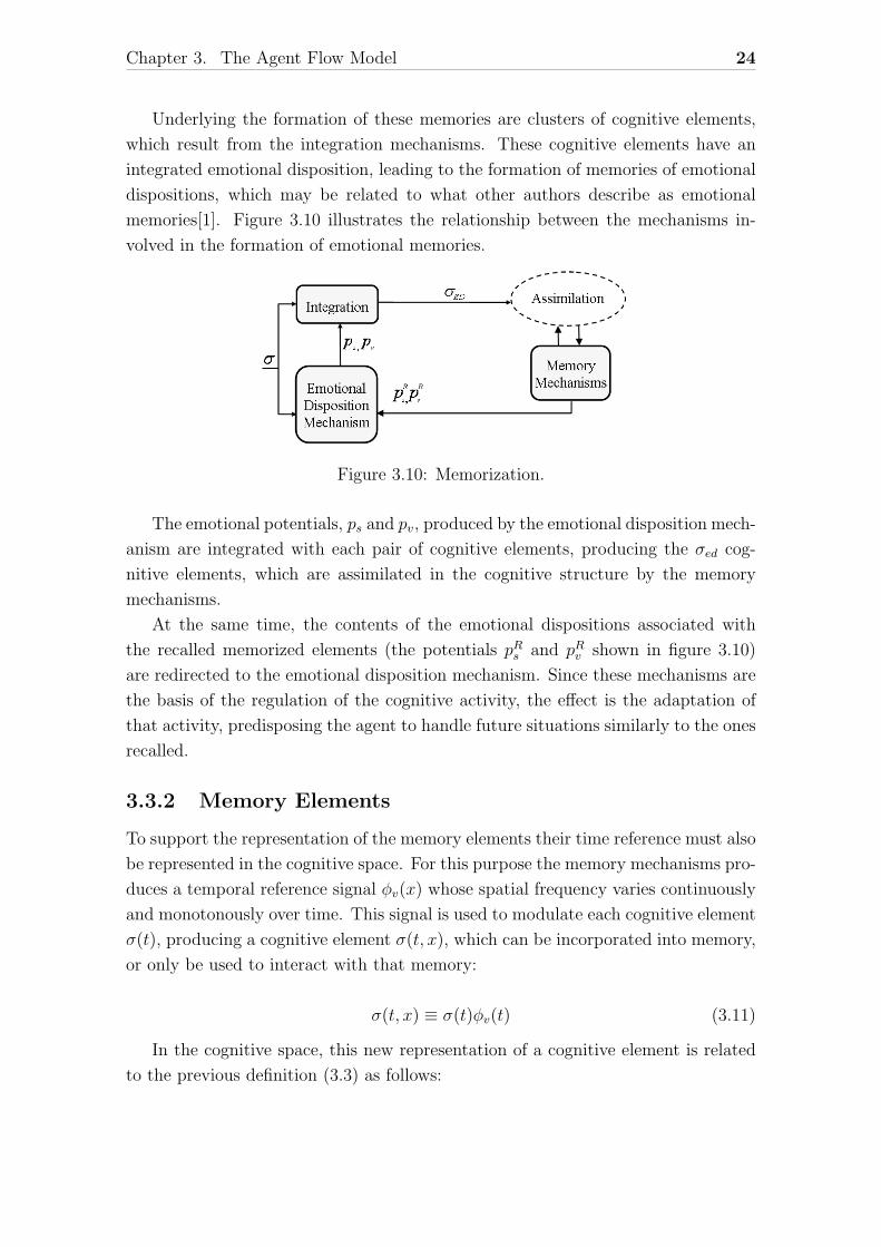
3.3.3 Integration of the Base and Memory Mechanisms
Given the inherently associative and parallel nature of a memory field, the interac-
tion of a cognitive element with a memory field produces, potentially, a large number
of recalled memory elements with different activation intensities. Given this large
number of memories, an agent must decide on which to focus, or it will not be
possible to make a decision in time.
The attention focus mechanism, described above, deals with this problem by
restricting the attention of the cognitive processes to specific cognitive elements, in
this case memory elements, according to their emotional disposition. Figure 3.11
shows how the various mechanisms involved connect to each other.
Figure 3.11: Integration of memory in the base mechanisms.
Chapter 3. The Agent Flow Model 26
As you can see, the recalled memory elements σR are subject to the attention
focus before they could, eventually, participate in the cognitive activity. Such par-
ticipation depends on the emotional disposition that characterizes them and the
intensity of the depletion barrier of the attention field, which is determined by the
emotional disposition mechanisms through the emotional signals λ+ and λ−.
3.4 The Cognitive Processes
The cognitive processes, as shown in figure 3.1, Perception, Assimilation, Reasoning,
Decision and Action, represent generic processes, which may involve several specific
processes organized into different levels of detail. There are no restrictions on the
form of their implementation inherent to this agent model. What they have in
common is the access to the same information, through the attention field, and the
possibility to interact with the base mechanisms.
Chapter 4
Design and Implementation of theAutoFocus Platform
This chapter describes the objectives, the decisions and the implementation of the
AutoFocus platform as a Java library.
4.1 Objectives
This project had two main objectives: to clarify some aspects of the Agent Flow
Model and to provide the necessary tools to facilitate the development of agents
with this architecture.
Although the theory of the Agent Flow Model had been developed, as it was pre-
sented in the previous chapter, it had only been implemented and tested for specific
cases. Until the beginning of this project several prototypes existed, but both the
cognitive structure and the base mechanisms had been specifically implemented for
each one according to the problem addressed. Those prototypes were implemented
in the C language, with more emphasis in efficiency than in generality.
So, the AutoFocus platform was idealized to integrate the knowledge gathered
from each prototype and to provide a general reusable implementation of both the
cognitive structure and the base mechanisms, the key features of the Agent Flow
Model.
This implementation, as determined in the project specification, would take the
form of a Java library.
27
Chapter 4. Design and Implementation of the AutoFocus Platform 28
4.2 General Platform Conception
Using as source of inspiration the Rl-Glue[10], a standard for connecting reinforce-
ment learning agents to their respective environments, it was decided to divide the
platform into three subsystems: the Agent, the Environment and the AutoFocus-
Glue.
In theory, the RL-Glue is a protocol consisting of standard functions to facilitate
the exchange and comparison of agents and environments without limiting their
abilities. As software, RL-Glue is functionally a test harness to “plug in” agents,
environments and experiment programs without having to continually rewrite the
connecting code for these pieces.
Using this approach in the Agent Flow Platform architecture lead to the creation
of the AutoFocusGlue.
The AutoFocusGlue
The AutoFocusGlue was introduced to control the communication between the agent
and the environment. The objective was to facilitate the decoupling between agents
and environments, so that different agents could be easily tested with different en-
vironments and vice-versa.
It also allows the execution of the agent and environment systems at different
rates of activation.
The Agent System
The Agent system is composed by the cognitive structure, the base mechanisms and
the cognitive processes, following the architecture of the Agent Flow Model (figure
3.1).
However there are some important differences. The perception and action pro-
cesses were relegated to the environment system implying that the agent system is
liberated from the responsibility of transforming sensory input into cognitive ele-
ments or transforming action mediators into the actual physical execution of that
action on the environment.
What this means is that the lower-level perception is done by the environment
which transmits the appropriate observation cognitive elements to the agent. But
the higher-level perception, which we will call interpretation, is done by the agent.
This interpretation includes, for example, deciding which role to assign to each
cognitive element.
As for the agents action, a similar approach is used where the agent communi-
cates the appropriate mediator cognitive elements to the environment which then
Chapter 4. Design and Implementation of the AutoFocus Platform 29
makes the necessary changes to the environment and agent states.
So the agent system can best be described as the “mental” side of the agent,
while its “physical” characteristics exist and are manipulated by the environment
system.
The Environment System
The environment system is responsible for maintaining the environment and agent
physical states. The environment is also responsible to provide the agent with a
cognitive space specification powerful enough for the agent to interact with the
environment.
When queried about its current state the environment must perform the trans-
duction and manipulation, inherent to the perception, necessary to provide the
agent with an observation that corresponds to the agent’s view of the environment.
That observation must be in accordance to the defined cognitive space, the reality
perceptible by the agent. When it is requested for the environment to execute an
agent’s action, it must transform the action into the proper agent and environment
modifications.
Chapter 4. Design and Implementation of the AutoFocus Platform 30
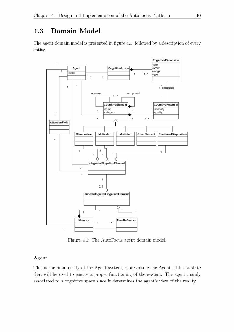
4.3 Domain Model
The agent domain model is presented in figure 4.1, followed by a description of every
entity.
Figure 4.1: The AutoFocus agent domain model.
Agent
This is the main entity of the Agent system, representing the Agent. It has a state
that will be used to ensure a proper functioning of the system. The agent mainly
associated to a cognitive space since it determines the agent’s view of the reality.
Chapter 4. Design and Implementation of the AutoFocus Platform 31
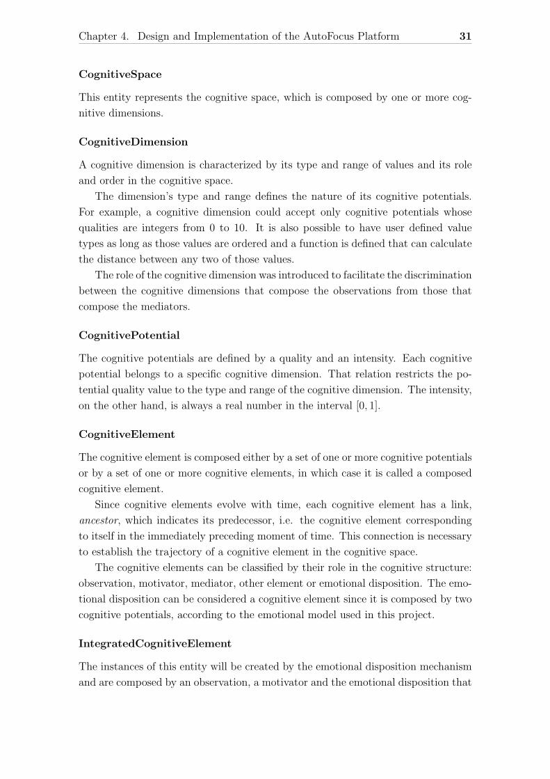
CognitiveSpace
This entity represents the cognitive space, which is composed by one or more cog-
nitive dimensions.
CognitiveDimension
A cognitive dimension is characterized by its type and range of values and its role
and order in the cognitive space.
The dimension’s type and range defines the nature of its cognitive potentials.
For example, a cognitive dimension could accept only cognitive potentials whose
qualities are integers from 0 to 10. It is also possible to have user defined value
types as long as those values are ordered and a function is defined that can calculate
the distance between any two of those values.
The role of the cognitive dimension was introduced to facilitate the discrimination
between the cognitive dimensions that compose the observations from those that
compose the mediators.
CognitivePotential
The cognitive potentials are defined by a quality and an intensity. Each cognitive
potential belongs to a specific cognitive dimension. That relation restricts the po-
tential quality value to the type and range of the cognitive dimension. The intensity,
on the other hand, is always a real number in the interval [0, 1].
CognitiveElement
The cognitive element is composed either by a set of one or more cognitive potentials
or by a set of one or more cognitive elements, in which case it is called a composed
cognitive element.
Since cognitive elements evolve with time, each cognitive element has a link,
ancestor, which indicates its predecessor, i.e. the cognitive element corresponding
to itself in the immediately preceding moment of time. This connection is necessary
to establish the trajectory of a cognitive element in the cognitive space.
The cognitive elements can be classified by their role in the cognitive structure:
observation, motivator, mediator, other element or emotional disposition. The emo-
tional disposition can be considered a cognitive element since it is composed by two
cognitive potentials, according to the emotional model used in this project.
IntegratedCognitiveElement
The instances of this entity will be created by the emotional disposition mechanism
and are composed by an observation, a motivator and the emotional disposition that
Chapter 4. Design and Implementation of the AutoFocus Platform 32
results from their interaction.
AttentionField
It represents the set of integrated cognitive elements that are available to the cog-
nitive processes.
TimedIntegratedCognitiveElement
It is an aggregation of an integrated cognitive element and a time reference.
TimeReference
Represents a time reference used by the agent.
Memory
It consists of the integrated cognitive elements, referenced in time, that were mem-
orized by the agent.
Chapter 4. Design and Implementation of the AutoFocus Platform 33
4.4 The Agent, Environment and AutoFocusGlue
Systems
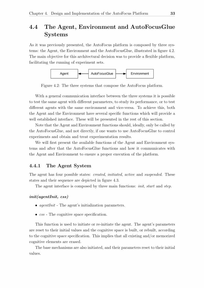
As it was previously presented, the AutoFocus platform is composed by three sys-
tems: the Agent, the Environment and the AutoFocusGlue, illustrated in figure 4.2.
The main objective for this architectural decision was to provide a flexible platform,
facilitating the running of experiment sets.
Figure 4.2: The three systems that compose the AutoFocus platform.
With a general communication interface between the three systems it is possible
to test the same agent with different parameters, to study its performance, or to test
different agents with the same environment and vice-versa. To achieve this, both
the Agent and the Environment have several specific functions which will provide a
well established interface. These will be presented in the rest of this section.
Note that the Agent and Environment functions should, ideally, only be called by
the AutoFocusGlue, and not directly, if one wants to use AutoFocusGlue to control
experiments and obtain and treat experimentation results.
We will first present the available functions of the Agent and Environment sys-
tems and after that the AutoFocusGlue functions and how it communicates with
the Agent and Environment to ensure a proper execution of the platform.
4.4.1 The Agent System
The agent has four possible states: created, initiated, active and suspended. These
states and their sequence are depicted in figure 4.3.
The agent interface is composed by three main functions: init, start and step.
init(agentInit, css)
• agentInit - The agent’s initialization parameters.
• css - The cognitive space specification.
This function is used to initiate or re-initiate the agent. The agent’s parameters
are reset to their initial values and the cognitive space is built, or rebuilt, according
to the cognitive space specification. This implies that all existing and/or memorized
cognitive elements are erased.
The base mechanisms are also initiated, and their parameters reset to their initial
values.

Chapter 4. Design and Implementation of the AutoFocus Platform 34
There are no initialization parameters implemented by default. These were intro-
duced to allow some freedom to the agent designer to implement specific initialization
tasks.
The agent system state is set to initiated.
Figure 4.3: The Agent system states.
start(agentExec, mainGoal)
• agentExec - Agent execution parameters.
• mainGoal - The main, or initial, agent goal (motivator).
This function can only be called when the agent system is in the initiated state.
The agent’s execution parameters are set, as well as the agent’s initial goal.
Like with the initialization parameters the agent’s execution parameters were
introduced to allow the agent designer to implement specific execution tasks.
The agent system changes to the active state.
step(envState) - action, timeTaken
• envState - The current environment state.
This function can only be called when the agent system is in the active state.
This is the main function of the agent computation. It takes the current environ-
ment state, in the form of one or more observations, and computes the next action.
What exactly are the individual steps and mechanisms used, will be described in
detail in the next section.
Chapter 4. Design and Implementation of the AutoFocus Platform 35
It returns the action selected and the time taken to compute it. The time taken
is the subjective time that the agent took to compute the action. This time is
constrained by the temporal focus configuration parameters, that set its maximum
value. But the time taken can also be less than that specified limit and that is why
it is returned by the step function.
If the action returned is “END”, signaling that all motivations of the agent have
been achieved, the agent state changes to suspended, if not, it continues active.
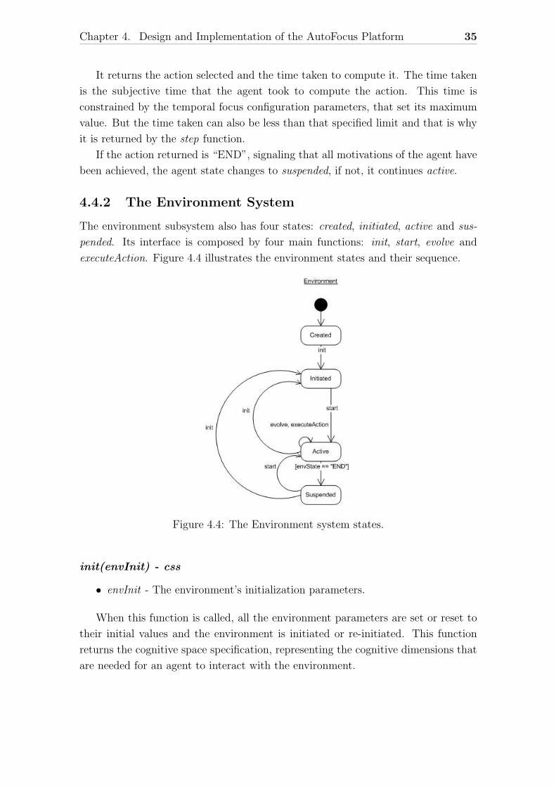
4.4.2 The Environment System
The environment subsystem also has four states: created, initiated, active and sus-
pended. Its interface is composed by four main functions: init, start, evolve and
executeAction. Figure 4.4 illustrates the environment states and their sequence.
Figure 4.4: The Environment system states.
init(envInit) - css
• envInit - The environment’s initialization parameters.
When this function is called, all the environment parameters are set or reset to
their initial values and the environment is initiated or re-initiated. This function
returns the cognitive space specification, representing the cognitive dimensions that
are needed for an agent to interact with the environment.
Chapter 4. Design and Implementation of the AutoFocus Platform 36
There are no initialization parameters implemented by default. These were in-
troduced to allow some freedom to the environment designer to implement specific
initialization tasks.
The environment system changes to the initiated state.
start(envExec) - envState
• envExec - The environment’s execution parameters.
This function can only be called when the environment system is in the initiated
state.
This function sets the execution parameters and starts the environment execu-
tion. It returns the current environment state, which in this case is the initial set of
observations.
Once more, the execution parameters were introduced to allow the environment
designer to implement specific execution tasks.
The environment system evolves to the active state.
evolve() - envState
This function can only be called when the environment system is in the active state.
The environment should evolve according to its internal dynamics and return
the resulting environment state.
If the resulting environment state is different from “END”, which signals the end
of the environment evolution, the environment system remains in the active state,
otherwise it turns to the suspended state.
executeAction(action) - envState
• action - The agent’s action.
This function can only be called when the environment system is in the active
state.
The environment executes the agent’s action by modifying accordingly the envi-
ronment and agent representations. It returns the resulting environment state.
If the resulting environment state is different than “END”, which signals the end
of the environment evolution, the environment system remains in the active state,
otherwise it turns to the suspended state.
4.4.3 The AutoFocusGlue System
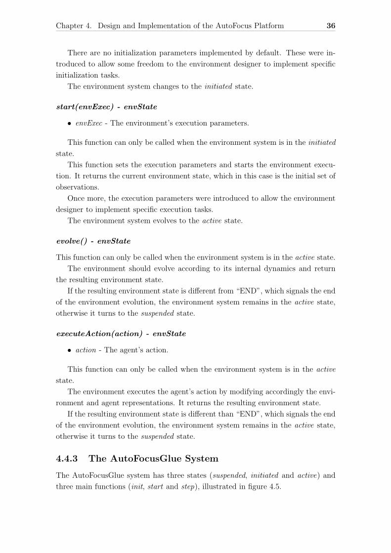
The AutoFocusGlue system has three states (suspended, initiated and active) and
three main functions (init, start and step), illustrated in figure 4.5.
Chapter 4. Design and Implementation of the AutoFocus Platform 37
Figure 4.5: The AutoFocusGlue system states.
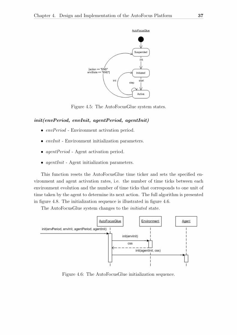
init(envPeriod, envInit, agentPeriod, agentInit)
• envPeriod - Environment activation period.
• envInit - Environment initialization parameters.
• agentPeriod - Agent activation period.
• agentInit - Agent initialization parameters.
This function resets the AutoFocusGlue time ticker and sets the specified en-
vironment and agent activation rates, i.e. the number of time ticks between each
environment evolution and the number of time ticks that corresponds to one unit of
time taken by the agent to determine its next action. The full algorithm is presented
in figure 4.8. The initialization sequence is illustrated in figure 4.6.
The AutoFocusGlue system changes to the initiated state.
Figure 4.6: The AutoFocusGlue initialization sequence.
Chapter 4. Design and Implementation of the AutoFocus Platform 38
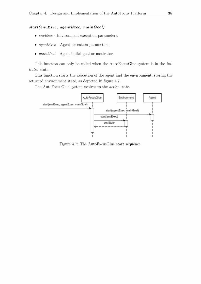
start(envExec, agentExec, mainGoal)
• envExec - Environment execution parameters.
• agentExec - Agent execution parameters.
• mainGoal - Agent initial goal or motivator.
This function can only be called when the AutoFocusGlue system is in the ini-
tiated state.
This function starts the execution of the agent and the environment, storing the
returned environment state, as depicted in figure 4.7.
The AutoFocusGlue system evolves to the active state.
Figure 4.7: The AutoFocusGlue start sequence.
Chapter 4. Design and Implementation of the AutoFocus Platform 39
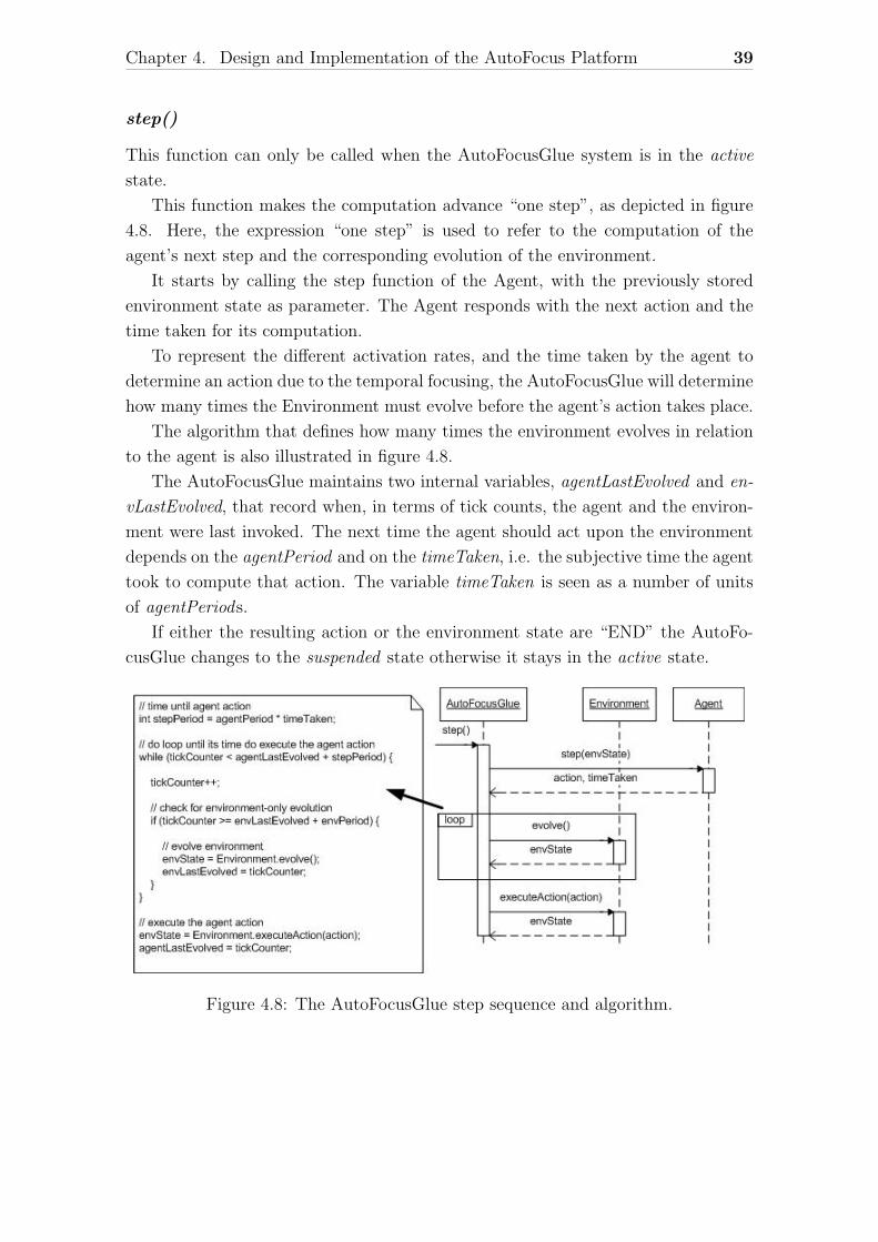
step()
This function can only be called when the AutoFocusGlue system is in the active
state.
This function makes the computation advance “one step”, as depicted in figure
4.8. Here, the expression “one step” is used to refer to the computation of the
agent’s next step and the corresponding evolution of the environment.
It starts by calling the step function of the Agent, with the previously stored
environment state as parameter. The Agent responds with the next action and the
time taken for its computation.
To represent the different activation rates, and the time taken by the agent to
determine an action due to the temporal focusing, the AutoFocusGlue will determine
how many times the Environment must evolve before the agent’s action takes place.
The algorithm that defines how many times the environment evolves in relation
to the agent is also illustrated in figure 4.8.
The AutoFocusGlue maintains two internal variables, agentLastEvolved and en-
vLastEvolved, that record when, in terms of tick counts, the agent and the environ-
ment were last invoked. The next time the agent should act upon the environment
depends on the agentPeriod and on the timeTaken, i.e. the subjective time the agent
took to compute that action. The variable timeTaken is seen as a number of units
of agentPeriods.
If either the resulting action or the environment state are “END” the AutoFo-
cusGlue changes to the suspended state otherwise it stays in the active state.
Figure 4.8: The AutoFocusGlue step sequence and algorithm.
Chapter 4. Design and Implementation of the AutoFocus Platform 40
4.4.4 Messages Definitions
The messages presented previously on the AutoFocus interfaces show a great deal
of information being passed between the agent and the environment. This section
will introduce the syntax and semantic of those messages.
Upon initialization the environment sends a CSS (cognitive space specification)
message to the agent.
Cognitive Space Specification (CSS)
The CSS indicates the cognitive dimensions that compose the cognitive space. It is
composed by: the total number of dimensions, the specification of the observation
dimensions and the specification of the action dimensions.
totalNumber|obsDimensions|actDimensions
Both the observation and action dimensions are described by their type and an
optional range of allowed values:
type1range1:type2range2:...:typeNrangeN
The type indicates the type of value of that particular dimension. For the mo-
ment, only two types are implemented, integers and doubles, indicated in a CSS de-
scription by i and d respectively. Expansion to other types, including user designed
types has also been considered and the implementation was chosen to facilitate that,
as will be mentioned in section 4.5.1.
Here is an CSS example:
4|i[0,1]:d[0,3.14]:d[1.5,3]|i[0,3]
This example has four dimensions, three observation dimensions and one action di-
mension.
Cognitive Potential and Cognitive Element Representation
The cognitive potential, as presented before, is composed by two values: intensity
and quality. In the messages exchanged we will refer to its quality value simply as
value, while the intensity value will be referred as its intensity.
The cognitive potential is always bound to a cognitive dimension that indicates
the type and range of the cognitive potential value, while the intensity is always a
real number, between 0 and 1.
The cognitive potentials have the following syntax:
Chapter 4. Design and Implementation of the AutoFocus Platform 41
value,intensity
For example, a cognitive potential with value 3.14 and intensity 0.5 is represented
by:
3.14,0.5
By aggregating several cognitive potentials we get a cognitive element.
v1,i1:v2,i2:...:vn,in
Here is an example of a cognitive element with a value 1 and intensity 1 in the
first dimension, value 3.14 and intensity 0.8 in the second dimension and value 11
and intensity 1 in the third dimension.
1,1:3.14,0.8:11,1
For simplicity sake, when the intensity is 1 it can be omitted. So the above
cognitive element could be rewritten has:
1:3.14,0.8:11
If the potential value corresponding to a certain dimension is not present, the
intensity value is assumed 0 and can also be omitted from the description of the
cognitive element. For example, if the second dimension of the previous example
had no value, then its intensity would be 0 and the description of the whole cognitive
element would be as follow:
1::11
Note that the cognitive elements must respect the format given by the CSS. For
example to represent an observation as a cognitive element, its cognitive potentials
must match the number, type and range of the specified observation dimensions.
Environment State Representation
Note that the term environment state is used here to refer to what the agent observes,
as it was explained previously. As such, this state representation can depict, and in
most cases it does, only a part of the entire environment state.
In simple cases, an environment state representation can consist of only one
cognitive element, i.e. a simple observation, but for more complex situations it is
conceived that an environment state can be composed by more than one cognitive
element that can represent different objects or parts of the environment. So there is
a need for those elements to be tagged with an object class and unique identification,
using the following syntax:
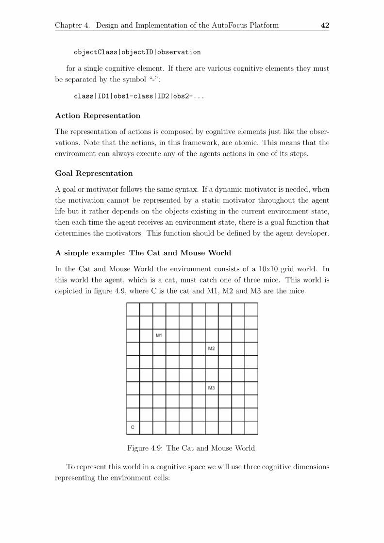
Chapter 4. Design and Implementation of the AutoFocus Platform 42
objectClass|objectID|observation
for a single cognitive element. If there are various cognitive elements they must
be separated by the symbol “-”:
class|ID1|obs1-class|ID2|obs2-...
Action Representation
The representation of actions is composed by cognitive elements just like the obser-
vations. Note that the actions, in this framework, are atomic. This means that the
environment can always execute any of the agents actions in one of its steps.
Goal Representation
A goal or motivator follows the same syntax. If a dynamic motivator is needed, when
the motivation cannot be represented by a static motivator throughout the agent
life but it rather depends on the objects existing in the current environment state,
then each time the agent receives an environment state, there is a goal function that
determines the motivators. This function should be defined by the agent developer.
A simple example: The Cat and Mouse World
In the Cat and Mouse World the environment consists of a 10x10 grid world. In
this world the agent, which is a cat, must catch one of three mice. This world is
depicted in figure 4.9, where C is the cat and M1, M2 and M3 are the mice.
Figure 4.9: The Cat and Mouse World.
To represent this world in a cognitive space we will use three cognitive dimensions
representing the environment cells:

Chapter 4. Design and Implementation of the AutoFocus Platform 43
• row number; from 1 to 10
• column number; from 1 to 10
• cell content;
– 0, empty
– 1, cat
– 2, mouse
– 3, cat and mouse
The cat can perform the following two types of action: move to an adjacent cell;
and catch a mouse, if there is one at his current position. To represent these actions
we will use two dimensions. One indicates a movement action and the other a catch
action.
• movement
– 1, move to the upper left cell
– 2, move to the upper cell
– 3, move to the upper right cell
– 4, move to the left cell
– 5, don’t move
– 6, move to the right cell
– 7, move to the down left cell
– 8, move to the down cell
– 9, move to the down right cell
• catch mouse
– 0, don’t catch mouse
– 1, catch mouse
So this world CSS, using our approach, is:
5|i[1,10]:i[1,10]:i[0,3]|i[1,9]:i[0,1]
Using this CSS, we can represent the situation presented in figure 4.9 with the
following environment state, composed by four observations:
cat|C|10:1:1-mouse|M1|3:3:2-mouse|M2|7:4:2-mouse|M3|7:7:2
A movement of the cat to the right cell is represented by the following cognitive
element corresponding to a mediator:
6:0
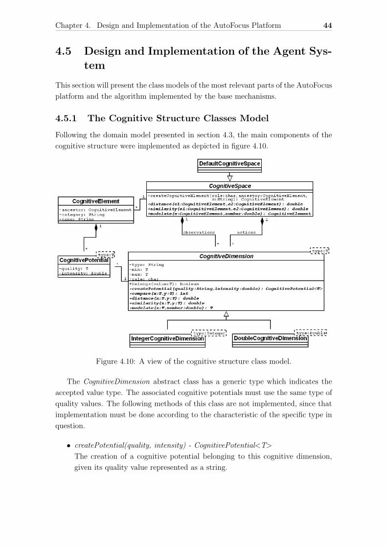
Chapter 4. Design and Implementation of the AutoFocus Platform 44
4.5 Design and Implementation of the Agent Sys-
tem
This section will present the class models of the most relevant parts of the AutoFocus
platform and the algorithm implemented by the base mechanisms.
4.5.1 The Cognitive Structure Classes Model
Following the domain model presented in section 4.3, the main components of the
cognitive structure were implemented as depicted in figure 4.10.
Figure 4.10: A view of the cognitive structure class model.
The CognitiveDimension abstract class has a generic type which indicates the
accepted value type. The associated cognitive potentials must use the same type of
quality values. The following methods of this class are not implemented, since that
implementation must be done according to the characteristic of the specific type in
question.
• createPotential(quality, intensity) - CognitivePotential<T>
The creation of a cognitive potential belonging to this cognitive dimension,
given its quality value represented as a string.
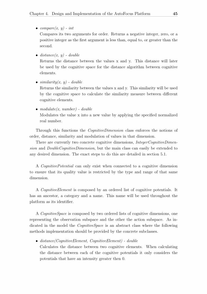
Chapter 4. Design and Implementation of the AutoFocus Platform 45
• compare(x, y) - int
Compares its two arguments for order. Returns a negative integer, zero, or a
positive integer as the first argument is less than, equal to, or greater than the
second.
• distance(x, y) - double
Returns the distance between the values x and y. This distance will later
be used by the cognitive space for the distance algorithm between cognitive
elements.
• similarity(x, y) - double
Returns the similarity between the values x and y. This similarity will be used
by the cognitive space to calculate the similarity measure between different
cognitive elements.
• modulate(x, number) - double
Modulates the value x into a new value by applying the specified normalized
real number.
Through this functions the CognitiveDimension class enforces the notions of
order, distance, similarity and modulation of values in that dimension.
There are currently two concrete cognitive dimensions, IntegerCognitiveDimen-
sion and DoubleCognitiveDimension, but the main class can easily be extended to
any desired dimension. The exact steps to do this are detailed in section 5.1.
A CognitivePotential can only exist when connected to a cognitive dimension
to ensure that its quality value is restricted by the type and range of that same
dimension.
A CognitiveElement is composed by an ordered list of cognitive potentials. It
has an ancestor, a category and a name. This name will be used throughout the
platform as its identifier.
A CognitiveSpace is composed by two ordered lists of cognitive dimensions, one
representing the observation subspace and the other the action subspace. As in-
dicated in the model the CognitiveSpace is an abstract class where the following
methods implementation should be provided by the concrete subclasses.
• distance(CognitiveElement, CognitiveElement) - double
Calculates the distance between two cognitive elements. When calculating
the distance between each of the cognitive potentials it only considers the
potentials that have an intensity greater then 0.
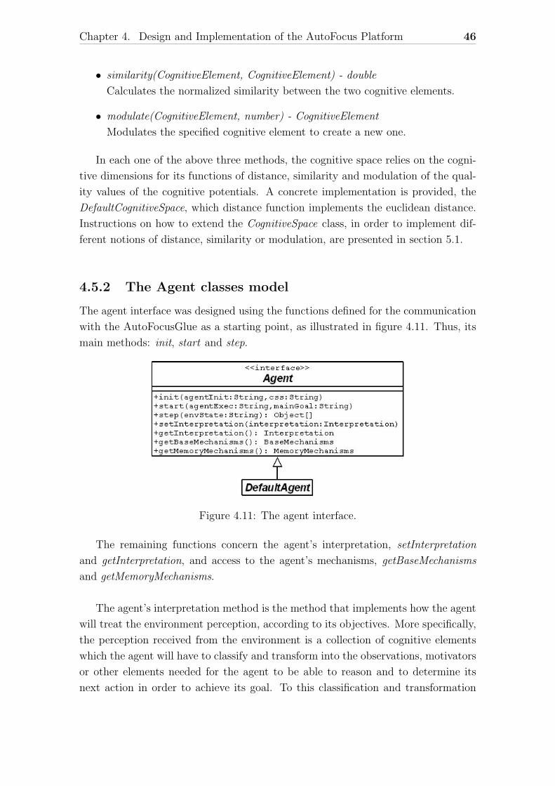
Chapter 4. Design and Implementation of the AutoFocus Platform 46
• similarity(CognitiveElement, CognitiveElement) - double
Calculates the normalized similarity between the two cognitive elements.
• modulate(CognitiveElement, number) - CognitiveElement
Modulates the specified cognitive element to create a new one.
In each one of the above three methods, the cognitive space relies on the cogni-
tive dimensions for its functions of distance, similarity and modulation of the qual-
ity values of the cognitive potentials. A concrete implementation is provided, the
DefaultCognitiveSpace, which distance function implements the euclidean distance.
Instructions on how to extend the CognitiveSpace class, in order to implement dif-
ferent notions of distance, similarity or modulation, are presented in section 5.1.
4.5.2 The Agent classes model
The agent interface was designed using the functions defined for the communication
with the AutoFocusGlue as a starting point, as illustrated in figure 4.11. Thus, its
main methods: init, start and step.
Figure 4.11: The agent interface.
The remaining functions concern the agent’s interpretation, setInterpretation
and getInterpretation, and access to the agent’s mechanisms, getBaseMechanisms
and getMemoryMechanisms.
The agent’s interpretation method is the method that implements how the agent
will treat the environment perception, according to its objectives. More specifically,
the perception received from the environment is a collection of cognitive elements
which the agent will have to classify and transform into the observations, motivators
or other elements needed for the agent to be able to reason and to determine its
next action in order to achieve its goal. To this classification and transformation
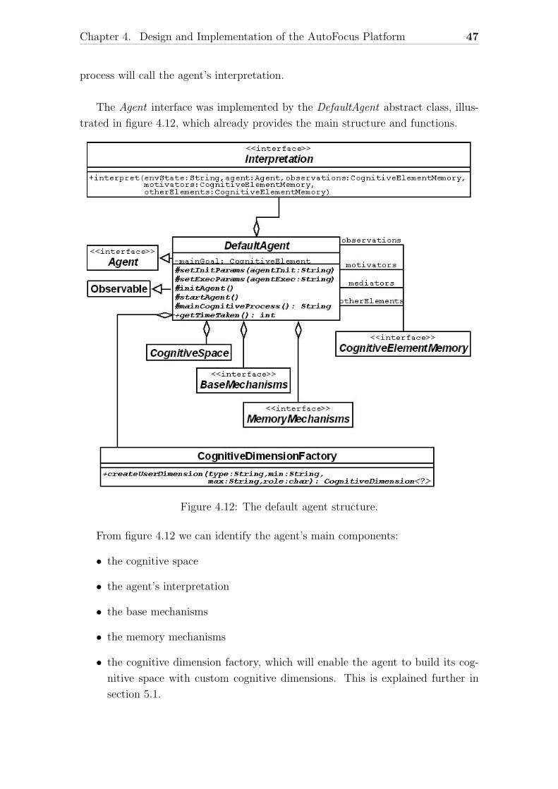
Chapter 4. Design and Implementation of the AutoFocus Platform 47
process will call the agent’s interpretation.
The Agent interface was implemented by the DefaultAgent abstract class, illus-
trated in figure 4.12, which already provides the main structure and functions.
Figure 4.12: The default agent structure.
From figure 4.12 we can identify the agent’s main components:
• the cognitive space
• the agent’s interpretation
• the base mechanisms
• the memory mechanisms
• the cognitive dimension factory, which will enable the agent to build its cog-
nitive space with custom cognitive dimensions. This is explained further in
section 5.1.
Chapter 4. Design and Implementation of the AutoFocus Platform 48
• four different cognitive element memories, one for each type of cognitive ele-
ment (observations, motivators, mediators and other elements). This is neces-
sary to preserve the cognitive elements ancestors, necessary to the calculations
performed by the base mechanisms.
The abstract methods that will have to be implemented by the agent’s designer
are:
• setInitParams(agentInit) - sets the agent’s initialization parameters.
• setExecParams(agentExec) - sets the agent’s execution parameters.
• initAgent() - initiates the agent.
• startAgent() - starts the agent execution.
• mainCognitiveProcess() - this is where the actual behavior or intelligence of
the agent is implemented and must return the agent’s action.
• getTimeTaken() - returns the time taken to process the agent’s action.
A more detailed explanation and instructions on how to implement them can be
found on section 5.3.
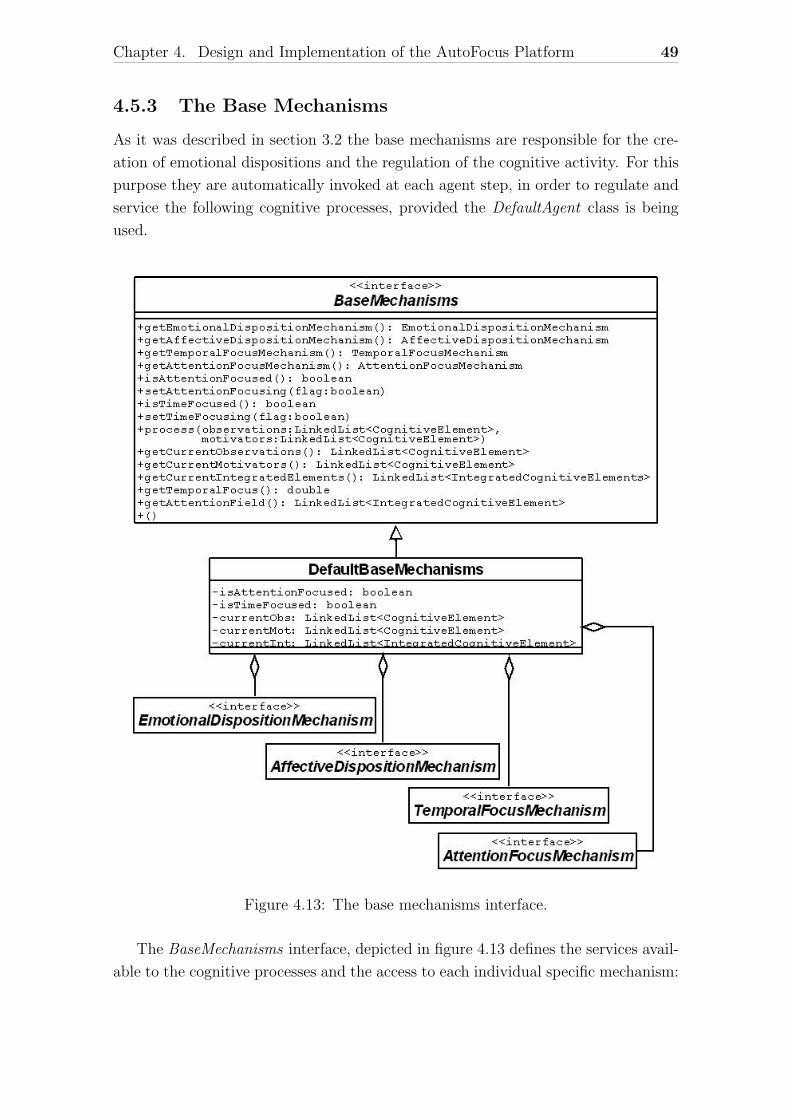
Chapter 4. Design and Implementation of the AutoFocus Platform 49
4.5.3 The Base Mechanisms
As it was described in section 3.2 the base mechanisms are responsible for the cre-
ation of emotional dispositions and the regulation of the cognitive activity. For this
purpose they are automatically invoked at each agent step, in order to regulate and
service the following cognitive processes, provided the DefaultAgent class is being
used.
Figure 4.13: The base mechanisms interface.
The BaseMechanisms interface, depicted in figure 4.13 defines the services avail-
able to the cognitive processes and the access to each individual specific mechanism:
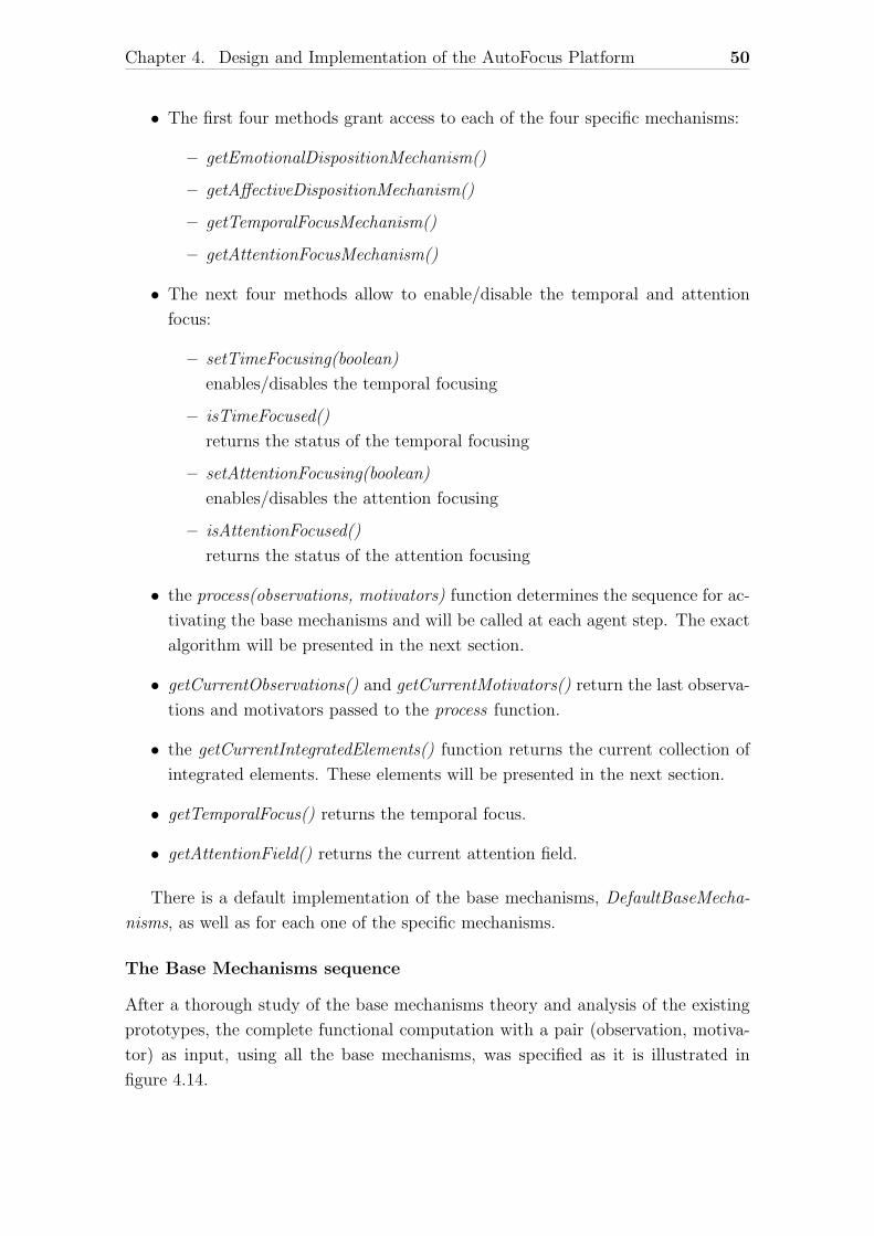
Chapter 4. Design and Implementation of the AutoFocus Platform 50
• The first four methods grant access to each of the four specific mechanisms:
– getEmotionalDispositionMechanism()
– getAffectiveDispositionMechanism()
– getTemporalFocusMechanism()
– getAttentionFocusMechanism()
• The next four methods allow to enable/disable the temporal and attention
focus:
– setTimeFocusing(boolean)
enables/disables the temporal focusing
– isTimeFocused()
returns the status of the temporal focusing
– setAttentionFocusing(boolean)
enables/disables the attention focusing
– isAttentionFocused()
returns the status of the attention focusing
• the process(observations, motivators) function determines the sequence for ac-
tivating the base mechanisms and will be called at each agent step. The exact
algorithm will be presented in the next section.
• getCurrentObservations() and getCurrentMotivators() return the last observa-
tions and motivators passed to the process function.
• the getCurrentIntegratedElements() function returns the current collection of
integrated elements. These elements will be presented in the next section.
• getTemporalFocus() returns the temporal focus.
• getAttentionField() returns the current attention field.
There is a default implementation of the base mechanisms, DefaultBaseMecha-
nisms, as well as for each one of the specific mechanisms.
The Base Mechanisms sequence
After a thorough study of the base mechanisms theory and analysis of the existing
prototypes, the complete functional computation with a pair (observation, motiva-
tor) as input, using all the base mechanisms, was specified as it is illustrated in
figure 4.14.
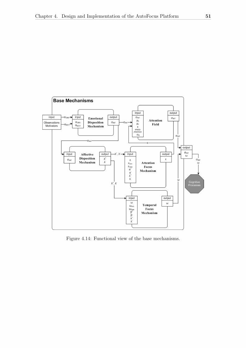
Chapter 4. Design and Implementation of the AutoFocus Platform 51
Figure 4.14: Functional view of the base mechanisms.
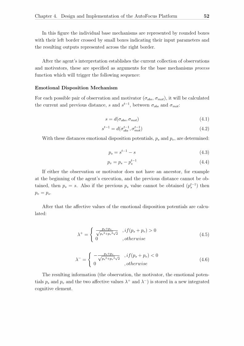
Chapter 4. Design and Implementation of the AutoFocus Platform 52
In this figure the individual base mechanisms are represented by rounded boxes
with their left border crossed by small boxes indicating their input parameters and
the resulting outputs represented across the right border.
After the agent’s interpretation establishes the current collection of observations
and motivators, these are specified as arguments for the base mechanisms process
function which will trigger the following sequence:
Emotional Disposition Mechanism
For each possible pair of observation and motivator (σobs, σmot), it will be calculated
the current and previous distance, s and st−1, between σobs and σmot:
s = d(σobs, σmot) (4.1)
st−1 = d(σt−1obs , σ
t−1mot) (4.2)
With these distances emotional disposition potentials, ps and pv, are determined:
ps = st−1 − s (4.3)
pv = ps − pt−1s (4.4)
If either the observation or motivator does not have an ancestor, for example
at the beginning of the agent’s execution, and the previous distance cannot be ob-
tained, then ps = s. Also if the previous ps value cannot be obtained (pt−1s ) then
pv = ps.
After that the affective values of the emotional disposition potentials are calcu-
lated:
λ+ =
{ps+pv√ps
2+pv2√
2, if(ps + pv) > 0
0 , otherwise(4.5)
λ− =
{− ps+pv√
ps2+pv
2√
2, if(ps + pv) < 0
0 , otherwise(4.6)
The resulting information (the observation, the motivator, the emotional poten-
tials ps and pv and the two affective values λ+ and λ−) is stored in a new integrated
cognitive element.
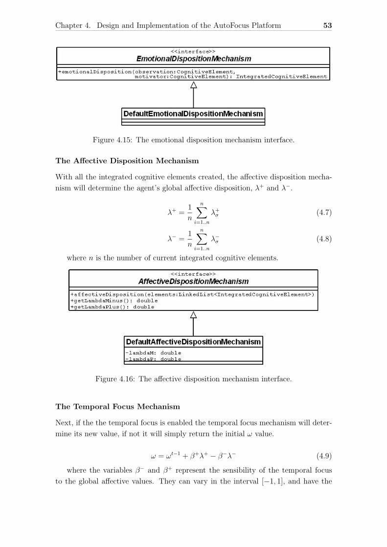
Chapter 4. Design and Implementation of the AutoFocus Platform 53
Figure 4.15: The emotional disposition mechanism interface.
The Affective Disposition Mechanism
With all the integrated cognitive elements created, the affective disposition mecha-
nism will determine the agent’s global affective disposition, λ+ and λ−.
λ+ =1
n
n∑i=1..n
λ+σ (4.7)
λ− =1
n
n∑i=1..n
λ−σ (4.8)
where n is the number of current integrated cognitive elements.
Figure 4.16: The affective disposition mechanism interface.
The Temporal Focus Mechanism
Next, if the the temporal focus is enabled the temporal focus mechanism will deter-
mine its new value, if not it will simply return the initial ω value.
ω = ωt−1 + β+λ+ − β−λ− (4.9)
where the variables β− and β+ represent the sensibility of the temporal focus
to the global affective values. They can vary in the interval [−1, 1], and have the
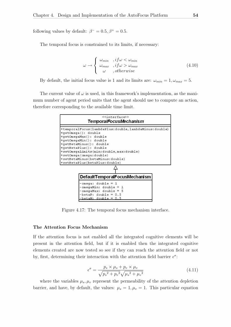
Chapter 4. Design and Implementation of the AutoFocus Platform 54
following values by default: β− = 0.5, β+ = 0.5.
The temporal focus is constrained to its limits, if necessary:
ω →
ωmin , ifω < ωminωmax , ifω > ωmaxω , otherwise
(4.10)
By default, the initial focus value is 1 and its limits are: ωmin = 1, ωmax = 5.
The current value of ω is used, in this framework’s implementation, as the maxi-
mum number of agent period units that the agent should use to compute an action,
therefore corresponding to the available time limit.
Figure 4.17: The temporal focus mechanism interface.
The Attention Focus Mechanism
If the attention focus is not enabled all the integrated cognitive elements will be
present in the attention field, but if it is enabled then the integrated cognitive
elements created are now tested so see if they can reach the attention field or not
by, first, determining their interaction with the attention field barrier εσ:
εσ =ps × µs + pv × µv√ps2 + pv2
√µs2 + µv2
(4.11)
where the variables µs, µv represent the permeability of the attention depletion
barrier, and have, by default, the values: µs = 1, µv = 1. This particular equation
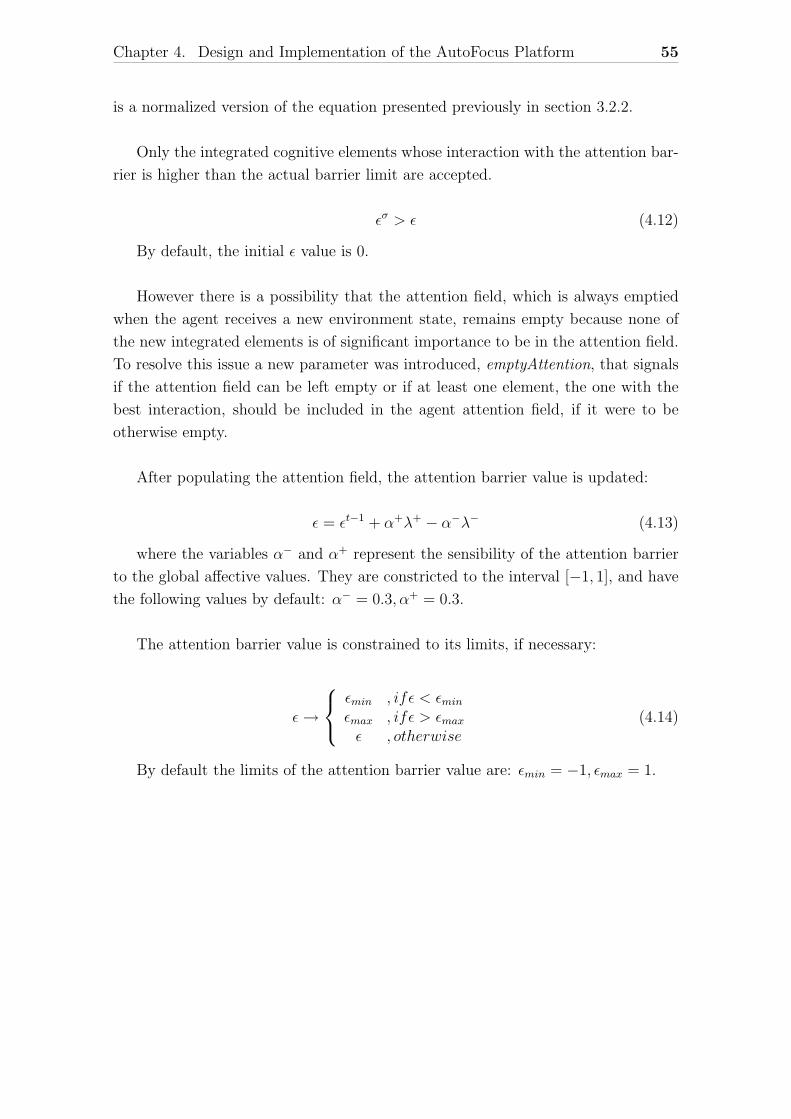
Chapter 4. Design and Implementation of the AutoFocus Platform 55
is a normalized version of the equation presented previously in section 3.2.2.
Only the integrated cognitive elements whose interaction with the attention bar-
rier is higher than the actual barrier limit are accepted.
εσ > ε (4.12)
By default, the initial ε value is 0.
However there is a possibility that the attention field, which is always emptied
when the agent receives a new environment state, remains empty because none of
the new integrated elements is of significant importance to be in the attention field.
To resolve this issue a new parameter was introduced, emptyAttention, that signals
if the attention field can be left empty or if at least one element, the one with the
best interaction, should be included in the agent attention field, if it were to be
otherwise empty.
After populating the attention field, the attention barrier value is updated:
ε = εt−1 + α+λ+ − α−λ− (4.13)
where the variables α− and α+ represent the sensibility of the attention barrier
to the global affective values. They are constricted to the interval [−1, 1], and have
the following values by default: α− = 0.3, α+ = 0.3.
The attention barrier value is constrained to its limits, if necessary:
ε→
εmin , ifε < εminεmax , ifε > εmaxε , otherwise
(4.14)
By default the limits of the attention barrier value are: εmin = −1, εmax = 1.
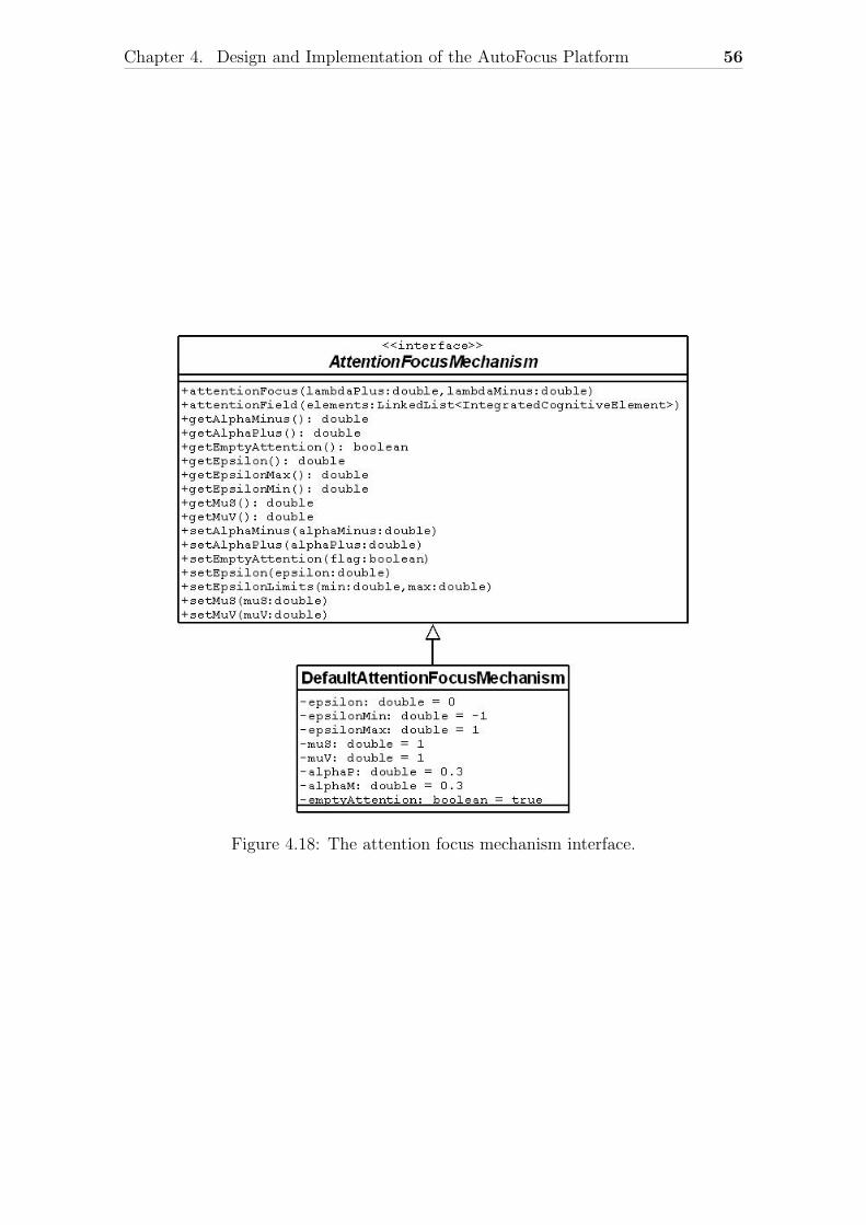
Chapter 4. Design and Implementation of the AutoFocus Platform 56
Figure 4.18: The attention focus mechanism interface.
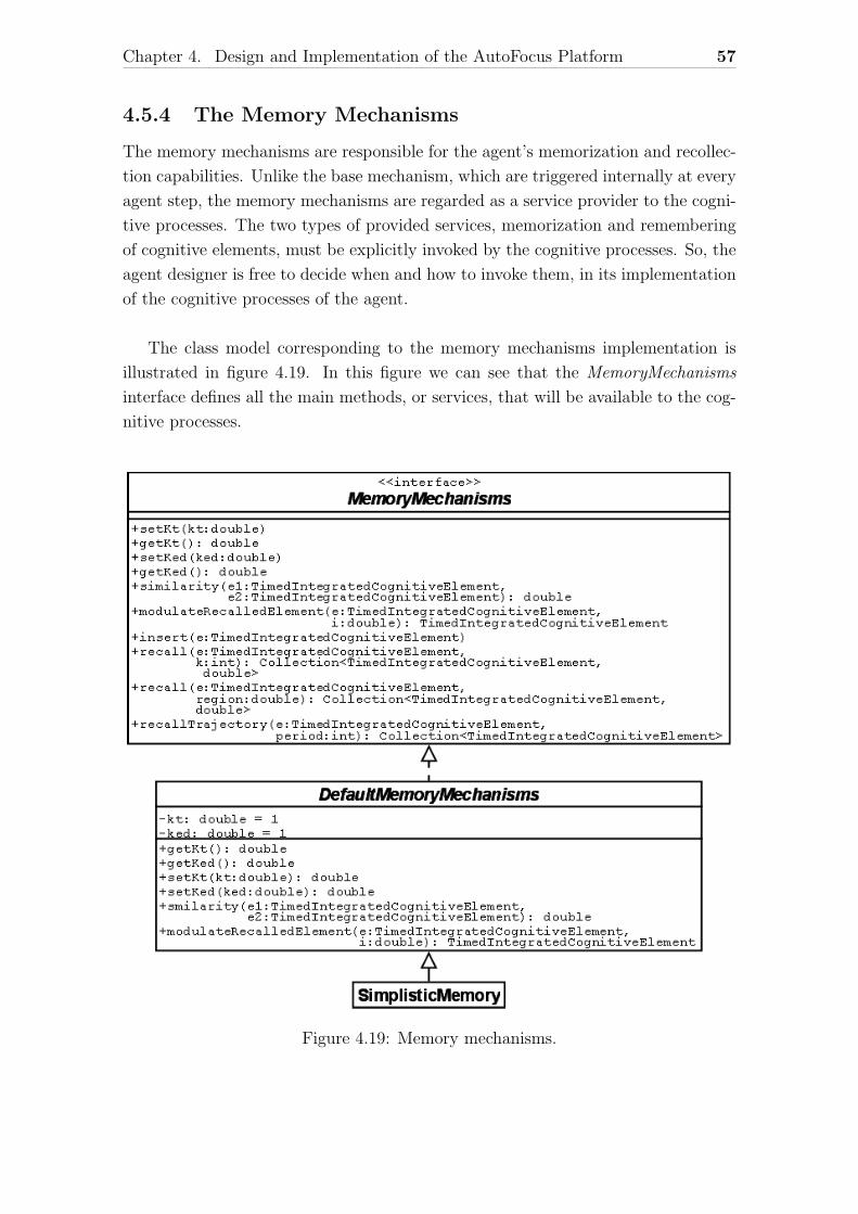
Chapter 4. Design and Implementation of the AutoFocus Platform 57
4.5.4 The Memory Mechanisms
The memory mechanisms are responsible for the agent’s memorization and recollec-
tion capabilities. Unlike the base mechanism, which are triggered internally at every
agent step, the memory mechanisms are regarded as a service provider to the cogni-
tive processes. The two types of provided services, memorization and remembering
of cognitive elements, must be explicitly invoked by the cognitive processes. So, the
agent designer is free to decide when and how to invoke them, in its implementation
of the cognitive processes of the agent.
The class model corresponding to the memory mechanisms implementation is
illustrated in figure 4.19. In this figure we can see that the MemoryMechanisms
interface defines all the main methods, or services, that will be available to the cog-
nitive processes.
Figure 4.19: Memory mechanisms.
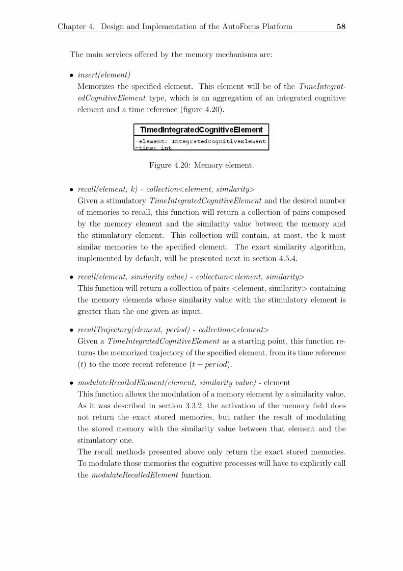
Chapter 4. Design and Implementation of the AutoFocus Platform 58
The main services offered by the memory mechanisms are:
• insert(element)
Memorizes the specified element. This element will be of the TimeIntegrat-
edCognitiveElement type, which is an aggregation of an integrated cognitive
element and a time reference (figure 4.20).
Figure 4.20: Memory element.
• recall(element, k) - collection<element, similarity>
Given a stimulatory TimeIntegratedCognitiveElement and the desired number
of memories to recall, this function will return a collection of pairs composed
by the memory element and the similarity value between the memory and
the stimulatory element. This collection will contain, at most, the k most
similar memories to the specified element. The exact similarity algorithm,
implemented by default, will be presented next in section 4.5.4.
• recall(element, similarity value) - collection<element, similarity>
This function will return a collection of pairs <element, similarity> containing
the memory elements whose similarity value with the stimulatory element is
greater than the one given as input.
• recallTrajectory(element, period) - collection<element>
Given a TimeIntegratedCognitiveElement as a starting point, this function re-
turns the memorized trajectory of the specified element, from its time reference
(t) to the more recent reference (t+ period).
• modulateRecalledElement(element, similarity value) - element
This function allows the modulation of a memory element by a similarity value.
As it was described in section 3.3.2, the activation of the memory field does
not return the exact stored memories, but rather the result of modulating
the stored memory with the similarity value between that element and the
stimulatory one.
The recall methods presented above only return the exact stored memories.
To modulate those memories the cognitive processes will have to explicitly call
the modulateRecalledElement function.
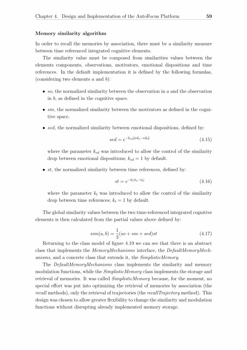
Chapter 4. Design and Implementation of the AutoFocus Platform 59
Memory similarity algorithm
In order to recall the memories by association, there must be a similarity measure
between time referenced integrated cognitive elements.
The similarity value must be composed from similarities values between the
elements components, observations, motivators, emotional dispositions and time
references. In the default implementation it is defined by the following formulas,
(considering two elements a and b):
• so, the normalized similarity between the observation in a and the observation
in b, as defined in the cognitive space.
• sm, the normalized similarity between the motivators as defined in the cogni-
tive space.
• sed, the normalized similarity between emotional dispositions, defined by:
sed = e−ked‖eda−edb‖ (4.15)
where the parameter ked was introduced to allow the control of the similarity
drop between emotional dispositions; ked = 1 by default.
• st, the normalized similarity between time references, defined by:
st = e−kt|ta−tb| (4.16)
where the parameter kt was introduced to allow the control of the similarity
drop between time references; kt = 1 by default.
The global similarity values between the two time-referenced integrated cognitive
elements is then calculated from the partial values above defined by:
sim(a, b) =1
3(so+ sm+ sed)st (4.17)
Returning to the class model of figure 4.19 we can see that there is an abstract
class that implements the MemoryMechanisms interface, the DefaultMemoryMech-
anisms, and a concrete class that extends it, the SimplisticMemory.
The DefaultMemoryMechanisms class implements the similarity and memory
modulation functions, while the SimplisticMemory class implements the storage and
retrieval of memories. It was called SimplisticMemory because, for the moment, no
special effort was put into optimizing the retrieval of memories by association (the
recall methods), only the retrieval of trajectories (the recallTrajectory method). This
design was chosen to allow greater flexibility to change the similarity and modulation
functions without disrupting already implemented memory storage.
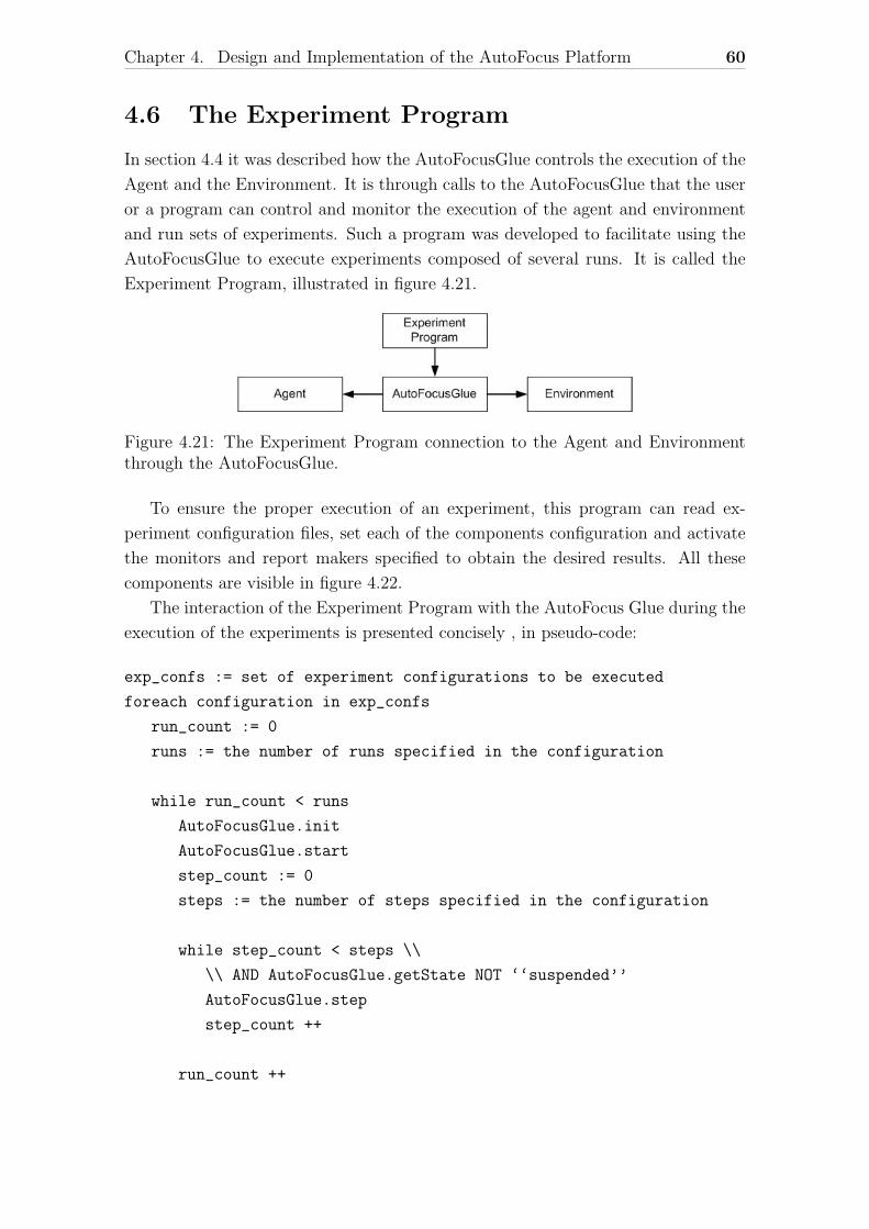
Chapter 4. Design and Implementation of the AutoFocus Platform 60
4.6 The Experiment Program
In section 4.4 it was described how the AutoFocusGlue controls the execution of the
Agent and the Environment. It is through calls to the AutoFocusGlue that the user
or a program can control and monitor the execution of the agent and environment
and run sets of experiments. Such a program was developed to facilitate using the
AutoFocusGlue to execute experiments composed of several runs. It is called the
Experiment Program, illustrated in figure 4.21.
Figure 4.21: The Experiment Program connection to the Agent and Environmentthrough the AutoFocusGlue.
To ensure the proper execution of an experiment, this program can read ex-
periment configuration files, set each of the components configuration and activate
the monitors and report makers specified to obtain the desired results. All these
components are visible in figure 4.22.
The interaction of the Experiment Program with the AutoFocus Glue during the
execution of the experiments is presented concisely , in pseudo-code:
exp_confs := set of experiment configurations to be executed
foreach configuration in exp_confs
run_count := 0
runs := the number of runs specified in the configuration
while run_count < runs
AutoFocusGlue.init
AutoFocusGlue.start
step_count := 0
steps := the number of steps specified in the configuration
while step_count < steps \\
\\ AND AutoFocusGlue.getState NOT ‘‘suspended’’
AutoFocusGlue.step
step_count ++
run_count ++
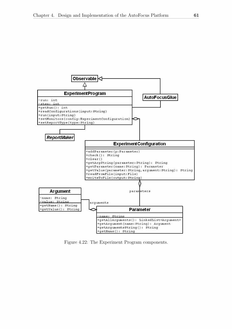
Chapter 4. Design and Implementation of the AutoFocus Platform 61
Figure 4.22: The Experiment Program components.
Chapter 4. Design and Implementation of the AutoFocus Platform 62
4.6.1 Experiment Configuration
An experiment configuration allows to store a given experiment configuration in a
file, so that it can be stored, rerun or easily modified. It is basically a set of param-
eters between two separation tokens: -startConf and -endConf respectively.
Each parameter will have one or more arguments using the following syntax:
-parameter arg1=value1;...;argN=valueN
There is a special case for the monitor parameters where the arguments have no
values. They simply indicate the variables the user wants to monitor: -monParameter
arg1;...;argN
The following sections will present the complete list of parameters available for
each of the different components and mechanisms. All the parameters are optional
unless stated otherwise.
AutoFocusGlue Parameters
• -cfgGlue <arguments>
The available arguments are envPeriod and agentPeriod which set the en-
vironment and agent execution period. The arguments have the following
format:
envPeriod=x;agentPeriod=y
(This parameter is mandatory.)
• -monGlue <arguments>
Activates the glue monitors. The available monitors are:
– tick - The AutoFocusGlue tick counter.
– glueStep - The number of AutoFocusGlue steps executed so far.
– envState - The environment state (agent’s perception).
– envLastEvolved - The tick when the environment was last evolved.
– action - The last agent action.
– timetaken - The last time taken by the agent.
– agentLastEvolved - The tick of the agent’s last step.
The special argument all will activate all of the above monitors.
Chapter 4. Design and Implementation of the AutoFocus Platform 63
Environment Parameters
The AutoFocus platform does not impose any restrictions to the environment im-
plementations, beyond the necessary communication interface. The environment
parameters, described below, should therefore be designed by the environment’s
developer.
• -iniEnvironment <arguments>
Sets the environment initialization variables. These variables are implemented
by the environment developer.
• -exeEnvironment <arguments>
Sets the environment execution variables. They follow the same format as
above.
• -monEnvironment <arguments>
Sets the environment monitors, i.e. indicates to the platform what are the
implemented variables that the user wants to monitor.
Agent Parameters
Like with the environment parameters, there are no restrictions to the agent’s pa-
rameters and their implementation is left to the agent designer.
• -iniAgent <arguments>
Sets the agent initialization variables.
• -exeAgent <arguments>
Sets the agent execution variables.
• -monAgent <arguments>
Sets the agent monitors.
A special value ”all” will activate all implemented monitors.
Base Mechanisms Parameters
• -cfgBaseMechanisms <arguments>
Configures the Base Mechanisms. The available arguments are:
– isTimeFocused - Allows the activation/deactivation of the temporal fo-
cus. (either true or false; false by default)
– isAttentionFocused - Allows the activation/deactivation of the atten-
tion focus. (either true or false; false by default)
Chapter 4. Design and Implementation of the AutoFocus Platform 64
• -monBaseMechanisms <arguments>
Activates the Base Mechanisms monitors. The special argument all activates
all the monitors.
– isTimeFocused - Indicates whether the time focusing mechanisms are
active or not.
– isAttentionFocused - Indicates whether the attention focusing mecha-
nisms are active or not.
– observations - The current set of cognitive elements supplied to the
base mechanisms as observations.
– motivators - The current set of cognitive elements supplied to the base
mechanisms as motivators.
– integrated - The current integrated cognitive elements.
– temporalFocus - The temporal focus activity rate.
– attentionFocusSize - The number of integrated cognitive elements present
in the attention field.
– attentionFocus - The integrated cognitive elements that compose the
attention field.
Affective Disposition Parameters
• -monAffectiveDisposition <arguments>
Activates the affective disposition monitors. The special argument all acti-
vates all the monitors.
– lambdaM - λ− value.
– lambdaP - λ+ value.
Temporal Focus Parameters
• -cfgTemporalFocus <arguments>
Allows the configuration of the temporal focus mechanisms.
– omega - (ω), the temporal focus initial value.
(ω ∈ [ωmin, ωmax]; ω = 1 by default)
– omegaMin - (ωmin), the minimum limit of the temporal focus value.
(ωmin = 1 by default)
– omegaMax - (ωmax), the maximum limit of the temporal focus value.
(ωmax = 5 by default)
Chapter 4. Design and Implementation of the AutoFocus Platform 65
– betaM - (β−), represents the sensibility of the temporal focus to the af-
fective value λ−.
(β− ∈ [−1, 1]; β− = 0.5 by default)
– betaP - (β+), represents the sensibility of the temporal focus to the af-
fective value λ+.
(β+ ∈ [−1, 1]; β+ = 0.5 by default)
• -monTemporalFocus <arguments>
Activates the temporal focus monitors. The special argument all activates
all the monitors.
– omega - ω value.
– omegaMin - ωmin value.
– omegaMax - ωmax value.
– betaM - β− value.
– betaP - β+ value.
Attention Focus Parameters
• -cfgAttentionFocus <arguments>
Allows the configuration of the attention focus mechanisms.
– epsilon - (ε), the attention barrier initial value.
(ε ∈ [εmin, εmax]; ε = 0 by default)
– epsilonMin - (εmin), the minimum limit of the attention barrier value.
(εmin = −1 by default)
– epsilonMax - (εmax), the maximum limit of the attention barrier value.
(εmax = 1 by default)
– alphaM - (α−), represents the sensibility of the attention barrier to the
affective value λ−.
(α− ∈ [−1, 1]; α− = 0.3 by default)
– alphaP - (α+), represents the sensibility of the attention barrier to the
affective value λ+.
(α+ ∈ [−1, 1]; α+ = 0.3 by default)
– muS - (µs), the permeability coefficient that determines the influence of
the emotional cognitive potential ps.
(µs = 1 by default)
Chapter 4. Design and Implementation of the AutoFocus Platform 66
– muV - (µv), the Permeability coefficient that determines the influence of
the emotional cognitive potential pv.
(µv = 1 by default)
– emptyAttention - Allows the agent to have an empty attention field or
not, whether the parameter is set to ”true” or ”false”.
(true by default)
• -monAttentionFocus <arguments>
Activates the attention focus monitors. The special argument all activates
all the monitors.
– epsilon - ε value.
– epsilonMin - εmin value.
– epsilonMax - εmax value.
– alphaM - α− value.
– alphaP - α+ value.
– muS - µs value.
– muV - µv value.
– emptyAttention - Display if the agent can have an empty attention field
or not.
– attentionSize - The number of integrated cognitive elements currently
in the attention field.
– attentionField - The attention field.
Memory Mechanisms Parameters
• -cfgMemory <arguments>
Configures the memory mechanisms.
– ked - (ked) The factor that influences the emotional disposition similari-
ties.
(ked = 1, by default)
– kt - (kt) The factor that influences the time similarities.
(kt = 1, by default)
• -monMemory <arguments>
Activates the memory mechanisms monitors. The special argument all acti-
vates all the monitors.
– ked - ked value.
– kt - kt value.
Chapter 4. Design and Implementation of the AutoFocus Platform 67
Experiment Program Parameters
• -cfgExperiment <arguments>
Configures the experiment program.
– end - The experiment end condition. It can be the number of steps to
be invoked to the AutoFocusGlue or END to signal that the experiment
should continue to run until either the environment or agent signal that
they have stopped.
(This argument is mandatory.)
– run - The number of runs to execute.
(1 by default)
– name - The name of the experiment.
(This argument is mandatory.)
• -monExperiment <arguments>
Activates the experiment program monitors. The special argument all acti-
vates all the monitors.
– run - The current run being executed.
Report Parameters
• -cfgReport <arguments>
Configures the report maker.
– type - The type of report to be generated. Currently there are two types:
∗ screen - Simply outputs the content of the monitors to the screen.
∗ csv - Generates a comma separated values file.
(screen by default)
– output - The directory where the reports will be created.
A simple configuration example
Here is a simple example of an experiment configuration:
-startConf
-cfgGlue envPeriod=1;agentPeriod=1
-cfgExperiment end=100;run=10;name=example
-endConf
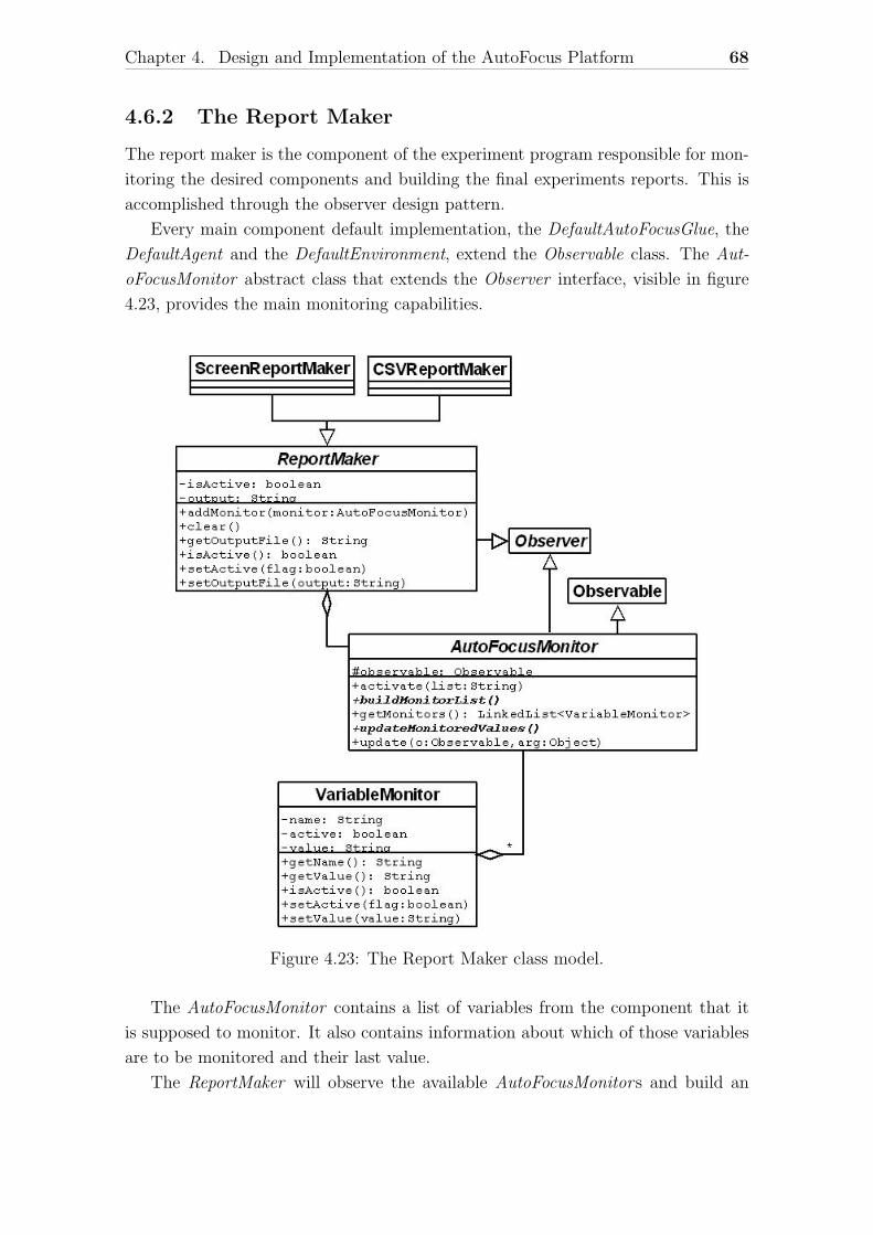
Chapter 4. Design and Implementation of the AutoFocus Platform 68
4.6.2 The Report Maker
The report maker is the component of the experiment program responsible for mon-
itoring the desired components and building the final experiments reports. This is
accomplished through the observer design pattern.
Every main component default implementation, the DefaultAutoFocusGlue, the
DefaultAgent and the DefaultEnvironment, extend the Observable class. The Aut-
oFocusMonitor abstract class that extends the Observer interface, visible in figure
4.23, provides the main monitoring capabilities.
Figure 4.23: The Report Maker class model.
The AutoFocusMonitor contains a list of variables from the component that it
is supposed to monitor. It also contains information about which of those variables
are to be monitored and their last value.
The ReportMaker will observe the available AutoFocusMonitors and build an
Chapter 4. Design and Implementation of the AutoFocus Platform 69
appropriate report from the actively monitored variables. There are currently two
types of report makers: ScreenReportMaker which simply outputs the current values
to the standard output mechanism, and the CSVReportMaker which builds a csv
(comma separated values) file.
Instructions about how to develop user defined monitors are presented on section
5.4.
4.6.3 Graphical representation
A unified approach to the graphical representation of the agents and/or environ-
ments was beyond the objectives of the current AutoFocus platform iteration but
it can be easily accomplished using the same approach as the report maker. Sim-
ply implement an observer for the desired component, agent or environment, which
updates a graphical representation. An example of this approach is presented in
section 6.1.2.
Chapter 5
Developing a prototype
In this section it will be explained how to build an AutoFocus agent and environment
using the presented framework.
5.1 Defining the cognitive structure
The first thing to consider is how the desired situation can be described in terms of
cognitive dimensions in order to design a cognitive space able to fully represent the
agent’s perception and objectives. This consist in choosing the number, order, type
and range of the cognitive dimensions that compose the cognitive space that will be
used. Note that this cognitive space is divided in two subspaces: the observation
subspace, that will represent the agent’s perception, and the action subspace, that
will represent the agent’s actions.
There are currently two types of cognitive dimensions implemented: the Inte-
gerCognitiveDimension and the DoubleCognitiveDimension. These allow cognitive
potentials with integer and double quality values, respectively. They also determine
the distance, similarity and modulation functions for values in their domains which
will be used by the cognitive space algorithms to calculate the distance, similarity
and modulation of cognitive elements.
If these two cognitive dimensions are not enough or adequate for a specific situa-
tion, the platform allows the designer to alter or create other dimensions. Consider
that the prototype in question requires a nominative cognitive dimension whose val-
ues identify each type of objects present in the environment. One could use the
IntegerCognitiveDimension, but this dimensions distance function (the euclidean
distance) may not be adequate for this purpose and the Hamming distance should
be more appropriate.
To accomplish this we could create a new cognitive dimension, NominativeCog-
nitiveDimension, by extending the IntegerCognitiveDimension and reimplementing
70
Chapter 5. Developing a prototype 71
the distance function accordingly.
public class NominativeCognitiveDimension extends
IntegerCognitiveDimension {
public double distance(Integer x, Integer y) {
if (x == y)
return 0;
else
return 1;
}
}
In order for the platform to cope with new types of cognitive dimensions it will
be necessary to extend the cognitive dimension factory for the new dimension type.
Continuing with the previous example and supposing that the new type is identified
by the string ”n”, the following code example shows a possible solution:
public class NewCognitiveDimensionFactory
extends DefaultCognitiveDimensionFactory {
protected CognitiveDimension<?> createUserDimension(String type,
String min, String max, char role) {
if(type.equals("n"))
return new NominativeCognitiveDimension(type,
new Integer(min), new Integer(max), role);
else
return super(type, min, max, role);
}
}
The same can be done for the cognitive space, if the situation required a different
algorithm to calculate the distance or similarity between cognitive elements.
After implementing new cognitive dimensions or space, if needed, they have
to be specified explicitly to the agent through its constructor function DefaultA-
gent(CognitiveDimensionFactory factory, CognitiveSpace space). If no changes were
needed to the existing implemented cognitive structure then the default constructor
can be used, DefaultAgent().
Chapter 5. Developing a prototype 72
5.2 Implementing the environment
After establishing the cognitive structure to be used we can start implementing the
environment. It is not necessary that the environment state follows the exact same
structure that the cognitive one, but it has to be able to return the agent’s percep-
tion according to the defined cognitive structure.
To build the environment one must extend the DefaultEnvironment class and
implement its abstract functions:
• resetToDefault()
Resets the environment to its default state. It also resets the environment
initialization and execution parameters to their default values. This is useful
when there are several experiment runs to be executed and the environment
is expected to return to its default state at the start of every run. It is called
by the environment’s init function.
• setInitParams(envInit)
Sets the initialization parameters values. Exactly what or which are the initial-
ization parameters is left entirely for the prototype designer to specify. They
will be later stored in the experiment configuration and passed to the environ-
ment as an argument of the environment’s init function when it is invoked by
the AutoFocusGlue.
One thing to keep in mind and that will help to decide whether an parameter
should be considered for initialization or execution, is that after the environ-
ment’s initialization, the cognitive space specification (CSS) has to be com-
municated to the agent. So if there is a parameter that can influence that
CSS, it must be passed during the initialization and not after. For example,
if the environment’s dimension could be specified and the cognitive structure
included cognitive dimensions that indicated the position of the agent, then
the environment’s dimensions would be initialization parameters.
• initEnv()
Create and initialize the environment state. This function will also be called
through the environment’s init function, after the initialization parameters are
set.
• getCSS() - css
Returns the environment cognitive space specification. This will be the result
of the environment’s init function.
Chapter 5. Developing a prototype 73
• setExecParams(envExec)
Sets the execution parameters values. It is called by the environment’s start
function.
• startEnv()
Starts the environment execution. Also called by the environment’s start func-
tion.
• getEnvState() - envState
Returns the environment state, i.e. the agent’s perception of the environment,
not necessarily the entire environment state. It will be called to build the
result of the environment’s start, evolve and executeAction functions.
• envEvolve()
This method is responsible for the evolution of the environment to its next
state and is called by the environment’s evolve function.
• executeAgentAction(action)
Execute the agent’s action and is called by the environment’s executeAction
function.
5.3 Implementing the agent
Now with the cognitive structure and environment implemented, the agent can be
built. There are two separate parts of the agent: the agent itself and the agent’s
interpretation of the environment state (perception). This division was introduced
to allow an easier modification of agent’s interpretations.
To build the interpretation, one must implement the Interpretation interface
and its single method interpret(String environmentState, Agent agent, CognitiveEle-
mentMemory observations, CognitiveElementMemory motivators, CognitiveElement-
Memory otherElements).
To build the agent one must extend the DefaultAgent class and implement its
abstract functions:
• resetToDefault()
Resets the agent to its default state. It also resets the agent initialization and
execution parameters to their default values. It is called by the agent’s init
function.
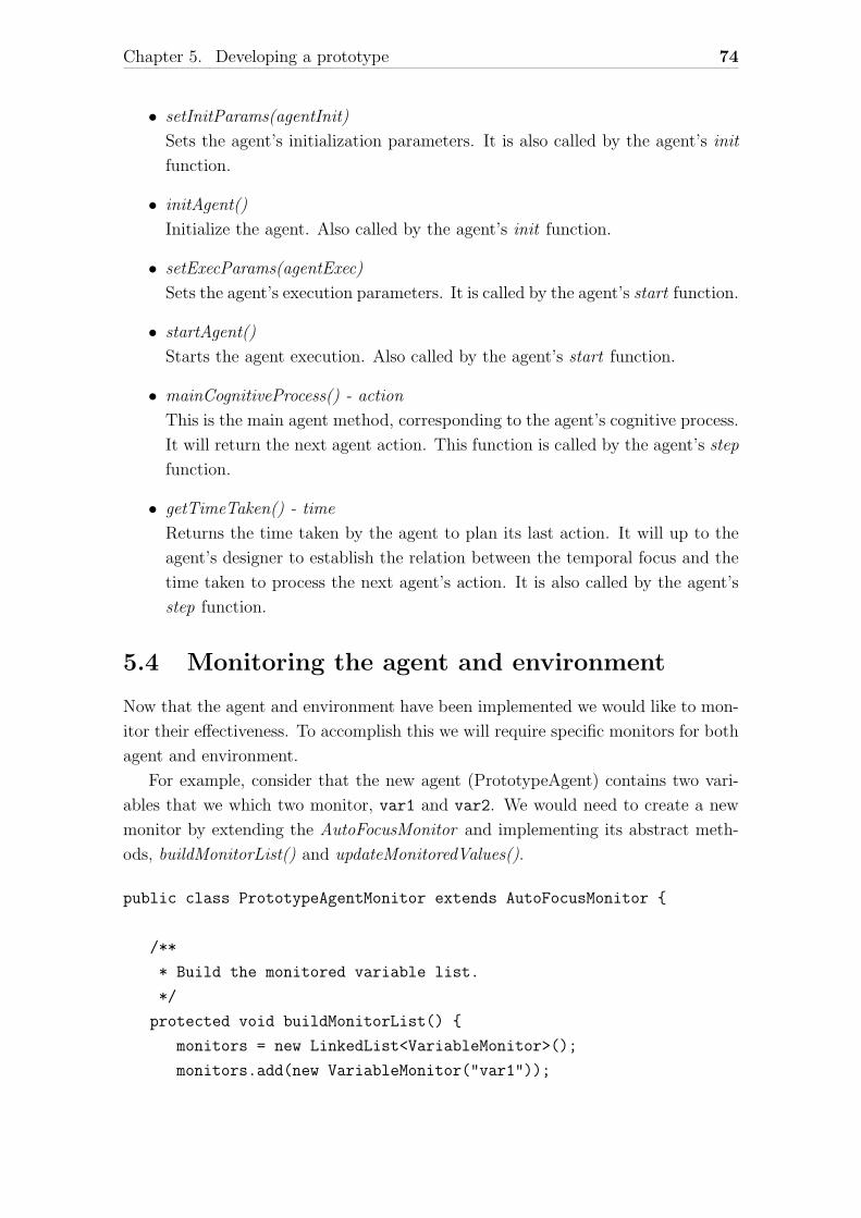
Chapter 5. Developing a prototype 74
• setInitParams(agentInit)
Sets the agent’s initialization parameters. It is also called by the agent’s init
function.
• initAgent()
Initialize the agent. Also called by the agent’s init function.
• setExecParams(agentExec)
Sets the agent’s execution parameters. It is called by the agent’s start function.
• startAgent()
Starts the agent execution. Also called by the agent’s start function.
• mainCognitiveProcess() - action
This is the main agent method, corresponding to the agent’s cognitive process.
It will return the next agent action. This function is called by the agent’s step
function.
• getTimeTaken() - time
Returns the time taken by the agent to plan its last action. It will up to the
agent’s designer to establish the relation between the temporal focus and the
time taken to process the next agent’s action. It is also called by the agent’s
step function.
5.4 Monitoring the agent and environment
Now that the agent and environment have been implemented we would like to mon-
itor their effectiveness. To accomplish this we will require specific monitors for both
agent and environment.
For example, consider that the new agent (PrototypeAgent) contains two vari-
ables that we which two monitor, var1 and var2. We would need to create a new
monitor by extending the AutoFocusMonitor and implementing its abstract meth-
ods, buildMonitorList() and updateMonitoredValues().
public class PrototypeAgentMonitor extends AutoFocusMonitor {
/**
* Build the monitored variable list.
*/
protected void buildMonitorList() {
monitors = new LinkedList<VariableMonitor>();
monitors.add(new VariableMonitor("var1"));
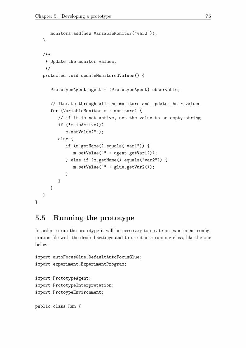
Chapter 5. Developing a prototype 75
monitors.add(new VariableMonitor("var2"));
}
/**
* Update the monitor values.
*/
protected void updateMonitoredValues() {
PrototypeAgent agent = (PrototypeAgent) observable;
// Iterate through all the monitors and update their values
for (VariableMonitor m : monitors) {
// if it is not active, set the value to an empty string
if (!m.isActive())
m.setValue("");
else {
if (m.getName().equals("var1")) {
m.setValue("" + agent.getVar1());
} else if (m.getName().equals("var2")) {
m.setValue("" + glue.getVar2());
}
}
}
}
}
5.5 Running the prototype
In order to run the prototype it will be necessary to create an experiment config-
uration file with the desired settings and to use it in a running class, like the one
below.
import autoFocusGlue.DefaultAutoFocusGlue;
import experiment.ExperimentProgram;
import PrototypeAgent;
import PrototypeInterpretation;
import ProtoypeEnvironment;
public class Run {
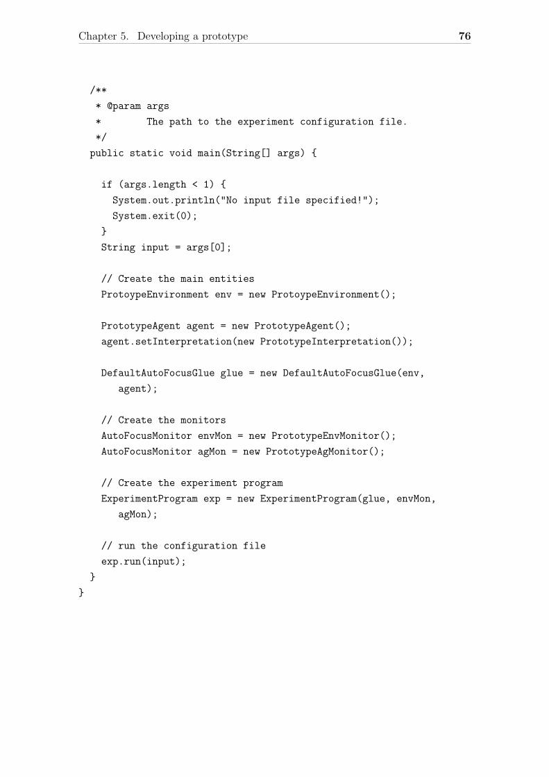
Chapter 5. Developing a prototype 76
/**
* @param args
* The path to the experiment configuration file.
*/
public static void main(String[] args) {
if (args.length < 1) {
System.out.println("No input file specified!");
System.exit(0);
}
String input = args[0];
// Create the main entities
ProtoypeEnvironment env = new ProtoypeEnvironment();
PrototypeAgent agent = new PrototypeAgent();
agent.setInterpretation(new PrototypeInterpretation());
DefaultAutoFocusGlue glue = new DefaultAutoFocusGlue(env,
agent);
// Create the monitors
AutoFocusMonitor envMon = new PrototypeEnvMonitor();
AutoFocusMonitor agMon = new PrototypeAgMonitor();
// Create the experiment program
ExperimentProgram exp = new ExperimentProgram(glue, envMon,
agMon);
// run the configuration file
exp.run(input);
}
}
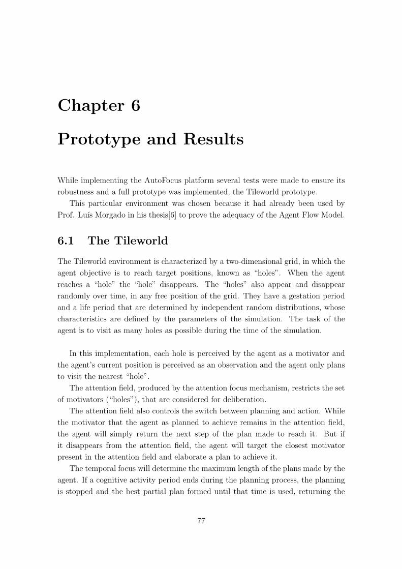
Chapter 6
Prototype and Results
While implementing the AutoFocus platform several tests were made to ensure its
robustness and a full prototype was implemented, the Tileworld prototype.
This particular environment was chosen because it had already been used by
Prof. Luıs Morgado in his thesis[6] to prove the adequacy of the Agent Flow Model.
6.1 The Tileworld
The Tileworld environment is characterized by a two-dimensional grid, in which the
agent objective is to reach target positions, known as “holes”. When the agent
reaches a “hole” the “hole” disappears. The “holes” also appear and disappear
randomly over time, in any free position of the grid. They have a gestation period
and a life period that are determined by independent random distributions, whose
characteristics are defined by the parameters of the simulation. The task of the
agent is to visit as many holes as possible during the time of the simulation.
In this implementation, each hole is perceived by the agent as a motivator and
the agent’s current position is perceived as an observation and the agent only plans
to visit the nearest “hole”.
The attention field, produced by the attention focus mechanism, restricts the set
of motivators (“holes”), that are considered for deliberation.
The attention field also controls the switch between planning and action. While
the motivator that the agent as planned to achieve remains in the attention field,
the agent will simply return the next step of the plan made to reach it. But if
it disappears from the attention field, the agent will target the closest motivator
present in the attention field and elaborate a plan to achieve it.
The temporal focus will determine the maximum length of the plans made by the
agent. If a cognitive activity period ends during the planning process, the planning
is stopped and the best partial plan formed until that time is used, returning the
77
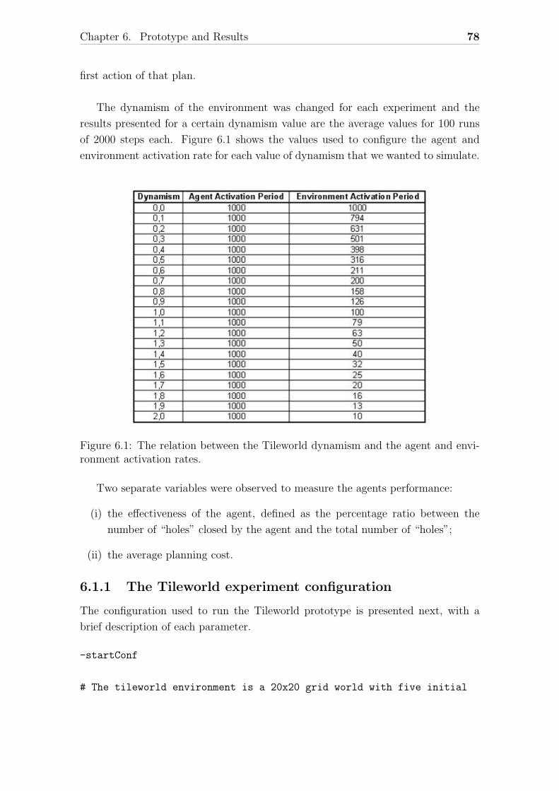
Chapter 6. Prototype and Results 78
first action of that plan.
The dynamism of the environment was changed for each experiment and the
results presented for a certain dynamism value are the average values for 100 runs
of 2000 steps each. Figure 6.1 shows the values used to configure the agent and
environment activation rate for each value of dynamism that we wanted to simulate.
Figure 6.1: The relation between the Tileworld dynamism and the agent and envi-ronment activation rates.
Two separate variables were observed to measure the agents performance:
(i) the effectiveness of the agent, defined as the percentage ratio between the
number of “holes” closed by the agent and the total number of “holes”;
(ii) the average planning cost.
6.1.1 The Tileworld experiment configuration
The configuration used to run the Tileworld prototype is presented next, with a
brief description of each parameter.
-startConf
# The tileworld environment is a 20x20 grid world with five initial
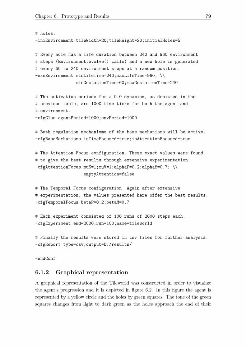
Chapter 6. Prototype and Results 79
# holes.
-iniEnvironment tileWidth=20;tileHeight=20;initialHoles=5
# Every hole has a life duration between 240 and 960 environment
# steps (Environment.evolve() calls) and a new hole is generated
# every 60 to 240 environment steps at a random position.
-exeEnvironment minLifeTime=240;maxLifeTime=960; \\
minGestationTime=60;maxGestationTime=240
# The activation periods for a 0.0 dynamism, as depicted in the
# previous table, are 1000 time ticks for both the agent and
# environment.
-cfgGlue agentPeriod=1000;envPeriod=1000
# Both regulation mechanisms of the base mechanisms will be active.
-cfgBaseMechanisms isTimeFocused=true;isAttentionFocused=true
# The Attention Focus configuration. These exact values were found
# to give the best results through extensive experimentation.
-cfgAttentionFocus muS=1;muV=1;alphaP=0.2;alphaM=0.7; \\
emptyAttention=false
# The Temporal Focus configuration. Again after extensive
# experimentation, the values presented here offer the best results.
-cfgTemporalFocus betaP=0.2;betaM=0.7
# Each experiment consisted of 100 runs of 2000 steps each.
-cfgExperiment end=2000;run=100;name=tileworld
# Finally the results were stored in csv files for further analysis.
-cfgReport type=csv;output=D:/results/
-endConf
6.1.2 Graphical representation
A graphical representation of the Tileworld was constructed in order to visualize
the agent’s progression and it is depicted in figure 6.2. In this figure the agent is
represented by a yellow circle and the holes by green squares. The tone of the green
squares changes from light to dark green as the holes approach the end of their
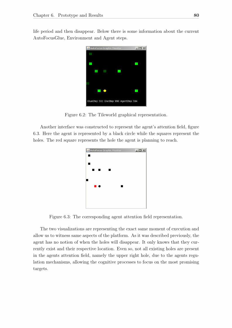
Chapter 6. Prototype and Results 80
life period and then disappear. Below there is some information about the current
AutoFocusGlue, Environment and Agent steps.
Figure 6.2: The Tileworld graphical representation.
Another interface was constructed to represent the agent’s attention field, figure
6.3. Here the agent is represented by a black circle while the squares represent the
holes. The red square represents the hole the agent is planning to reach.
Figure 6.3: The corresponding agent attention field representation.
The two visualizations are representing the exact same moment of execution and
allow us to witness same aspects of the platform. As it was described previously, the
agent has no notion of when the holes will disappear. It only knows that they cur-
rently exist and their respective location. Even so, not all existing holes are present
in the agents attention field, namely the upper right hole, due to the agents regu-
lation mechanisms, allowing the cognitive processes to focus on the most promising
targets.
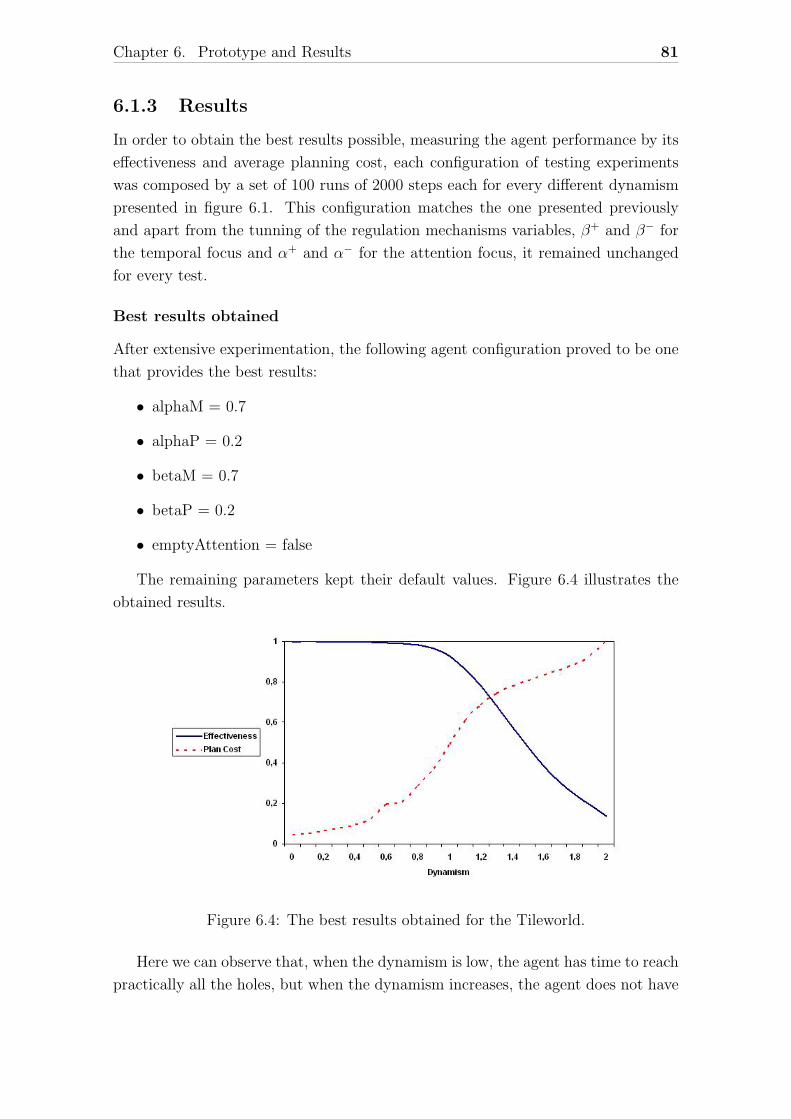
Chapter 6. Prototype and Results 81
6.1.3 Results
In order to obtain the best results possible, measuring the agent performance by its
effectiveness and average planning cost, each configuration of testing experiments
was composed by a set of 100 runs of 2000 steps each for every different dynamism
presented in figure 6.1. This configuration matches the one presented previously
and apart from the tunning of the regulation mechanisms variables, β+ and β− for
the temporal focus and α+ and α− for the attention focus, it remained unchanged
for every test.
Best results obtained
After extensive experimentation, the following agent configuration proved to be one
that provides the best results:
• alphaM = 0.7
• alphaP = 0.2
• betaM = 0.7
• betaP = 0.2
• emptyAttention = false
The remaining parameters kept their default values. Figure 6.4 illustrates the
obtained results.
Figure 6.4: The best results obtained for the Tileworld.
Here we can observe that, when the dynamism is low, the agent has time to reach
practically all the holes, but when the dynamism increases, the agent does not have

Chapter 6. Prototype and Results 82
enough time to reach every hole before they disappear and its effectiveness decreases.
That is also visible in the planning cost rise. Since there are more holes appearing
and disappearing, the agent is forced to re-plan more often. The reason why the
plan cost is not a linear function in comparison with the dynamism is because the
temporal focus forces the agent to have shorter cognitive activity periods, meaning
shorter plans.
Some additional results
As this platform relies largely in experimentation to determine the best agent config-
uration, here a few more results obtained using the previous configuration as starting
point and slightly changing some of the parameters.
Allowing the attention field to be empty
• emptyAttention = true
The results, illustrated in figure 6.5, show a global decline of the effectiveness
function while the planning cost remains basically the same. In this implementation,
when the attention field is empty the agent takes no action which is why, even with
a low dynamism the agent is incapable of reaching every hole. Possibly there could
be other implementations where the agent could take a random action that would
present better results.
Figure 6.5: Tileworld results allowing the attention field to be empty.
Changing the signal of the α and β parameters
• alphaM = -0.7
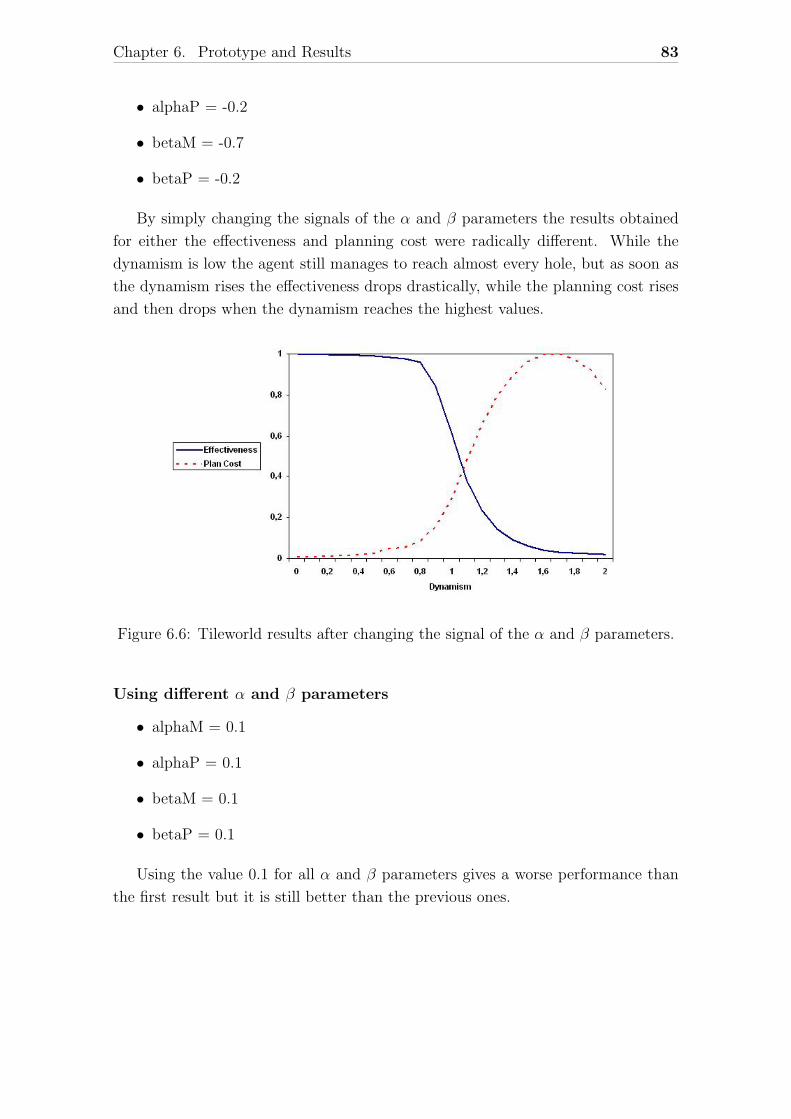
Chapter 6. Prototype and Results 83
• alphaP = -0.2
• betaM = -0.7
• betaP = -0.2
By simply changing the signals of the α and β parameters the results obtained
for either the effectiveness and planning cost were radically different. While the
dynamism is low the agent still manages to reach almost every hole, but as soon as
the dynamism rises the effectiveness drops drastically, while the planning cost rises
and then drops when the dynamism reaches the highest values.
Figure 6.6: Tileworld results after changing the signal of the α and β parameters.
Using different α and β parameters
• alphaM = 0.1
• alphaP = 0.1
• betaM = 0.1
• betaP = 0.1
Using the value 0.1 for all α and β parameters gives a worse performance than
the first result but it is still better than the previous ones.
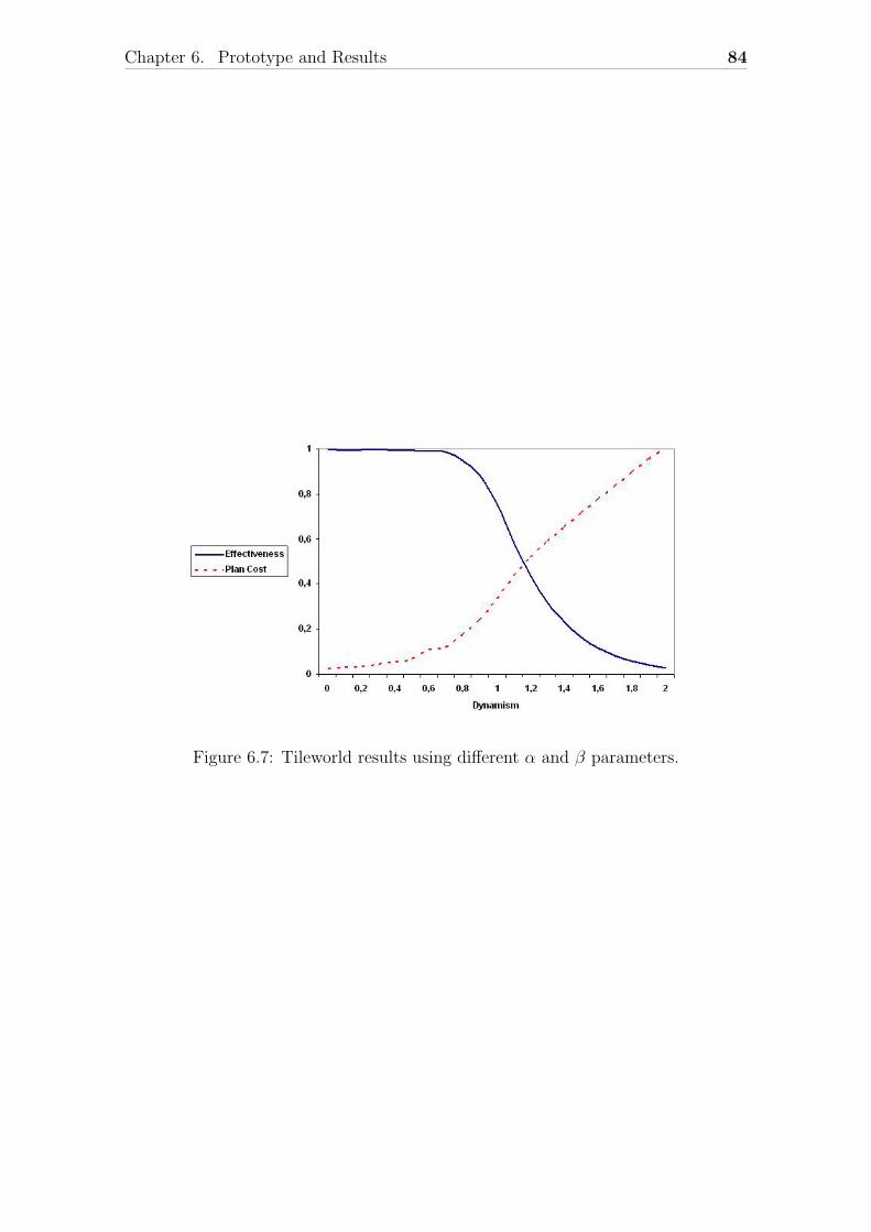
Chapter 6. Prototype and Results 84
Figure 6.7: Tileworld results using different α and β parameters.

Chapter 7
Conclusions
The developed AutoFocus platform was conceived to be a flexible and general im-
plementation of the Agent Flow Model theory. Also various aspects of the cognitive
structure and base mechanisms where polished which improved the knowledge avail-
able in order to provide a general usable framework.
As future work, it is planned to create base mechanisms capable of defining the
global emotional situation, which can be understood as the agent’s emotional state,
and to study how the AutoFocus agents behave in multi-agent environments.
85
Bibliography
[1] Antonio Damasio. A Second Chance for Emotion, pages 12–22. Oxford Uni-
versity Press, 2000.
[2] P. Ekman and R. J. Davidson. The nature of emotion: fundamental questions.
Oxford University Press, 1994.
[3] N. Fridja. The Emotions. Cambridge University Press, 1986.
[4] Peter Gardenfors. Conceptual Spaces. The MIT Press, 2000.
[5] H. Maturana and F. Varela. The Tree of Knowledge: The Biological Roots of
Human Understanding. Shambhala Publications, 1987.
[6] Luıs Morgado. Integracao de Emocao e Raciocınio em Agentes Inteligentes.
PhD thesis, Departamento de Informatica da Faculdade de Ciencias da Univer-
sidade de Lisboa, 2005.
[7] Luıs Morgado and Graca Gaspar. Abstraction level regulation of cognitive pro-
cessing through emotion-based attention mechanisms. In Lucas Paletta and
Erich Rome, editors, WAPCV, volume 4840 of Lecture Notes in Computer Sci-
ence, pages 59–74. Springer, 2007.
[8] Luıs Morgado and Graca Gaspar. A signal based approach to artificial agent
modeling. In Fernando Almeida e Costa, Luis Mateus Rocha, Ernesto Costa,
Inman Harvey, and Antonio Coutinho, editors, ECAL, volume 4648 of Lecture
Notes in Computer Science, pages 1050–1059. Springer, 2007.
[9] Pedro Neves. An implementation framework for emotion based adaptive agents.
Master’s thesis, Department of Informatics, University of Lisbon, November
2008. DI/FCUL TR-08-24.
[10] RL-Glue. A standard for connecting reinforcement learning agents and envi-
ronments. http://glue.rl-community.org/.
86