Embed Size (px)
Citation preview

1
Autodesk's VEX® Robotics Curriculum
Unit 2: Introduction to Autodesk Inventor

2 ■ Autodesk's VEX Robotics Unit 2: Introduction to Autodesk Inventor
Overview
In Unit 2: Introduction to Autodesk Inventor, you review the Autodesk® Inventor® user interface. Themain components are the application menu, Quick Access toolbar, ribbon, browser, shortcut menus,and shortcut keys.
You also review the modeling process with Autodesk Inventor. This includes creating sketches, parts,assembling parts, and documenting parts and assemblies.
Unit Objectives
After completing Unit 2: Introduction to Autodesk Inventor, you will be able to:
■ Review the Autodesk Inventor modeling process and the user interface.
Prerequisites and Resources
Before starting Unit 2: Introduction to Autodesk Inventor, you must have:
■ A working knowledge of the Windows operating system.■ Completed Unit 1: Introduction to VEX and Robotics > Getting Started with Autodesk Inventor.
Key Terms and Definitions
The following key terms are used in Unit 2: Introduction to Autodesk Inventor.
Term
Definition
Assembly Two or more components (parts or subassemblies) considered as a single model. Anassembly typically includes multiple components positioned absolutely and relatively(as required) with constraints that define both size and position.
Browser The graphical hierarchy showing relationships between geometric elements in parts,assemblies, and drawings. Icons represent sketches, features, constraints, or attributesfor each model. Objects are shown in the browser in the order in which they werecreated. Objects may also be edited, renamed, added, deleted, copied, and moved to adifferent location in the browser.
Dimension Parametric dimensions that control sketch size. When dimensions are changed, thesketch resizes. Dimensional constraints may be expressed as numeric constants, asvariables in equations, or in parameter files.
Drawing A 2D representation of a part or assembly. The drawing file type has an IDW extension.
Extrude A feature created by adding depth to a sketched profile. Feature shape is controlled byprofile shape, extrusion extent, and taper angle.
Overview ■ 3
Term
Definition
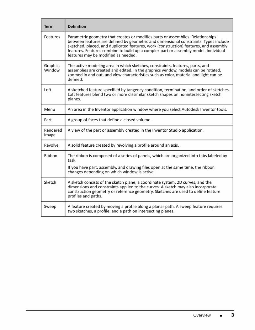
Features Parametric geometry that creates or modifies parts or assemblies. Relationshipsbetween features are defined by geometric and dimensional constraints. Types includesketched, placed, and duplicated features, work (construction) features, and assemblyfeatures. Features combine to build up a complex part or assembly model. Individualfeatures may be modified as needed.
GraphicsWindow
The active modeling area in which sketches, constraints, features, parts, andassemblies are created and edited. In the graphics window, models can be rotated,zoomed in and out, and view characteristics such as color, material and light can bedefined.
Loft A sketched feature specified by tangency condition, termination, and order of sketches.Loft features blend two or more dissimilar sketch shapes on nonintersecting sketchplanes.
Menu An area in the Inventor application window where you select Autodesk Inventor tools.
Part A group of faces that define a closed volume.
RenderedImage
A view of the part or assembly created in the Inventor Studio application.
Revolve A solid feature created by revolving a profile around an axis.
Ribbon The ribbon is composed of a series of panels, which are organized into tabs labeled bytask. If you have part, assembly, and drawing files open at the same time, the ribbonchanges depending on which window is active.
Sketch A sketch consists of the sketch plane, a coordinate system, 2D curves, and thedimensions and constraints applied to the curves. A sketch may also incorporateconstruction geometry or reference geometry. Sketches are used to define featureprofiles and paths.
Sweep A feature created by moving a profile along a planar path. A sweep feature requirestwo sketches, a profile, and a path on intersecting planes.

4 ■ Autodesk's VEX Robotics Unit 2: Introduction to Autodesk Inventor
Technical Overview
The following Autodesk Inventor tools are used in Unit 2: Introduction to Autodesk Inventor: Icon
Name
Description
Two PointRectangle
Create a two-point rectangle.
GeneralDimension
Add dimensions to a sketch. Dimensions control the size of a part. Theycan be expressed as numeric constants, as variables in an equation, or inparameter files.
Fillet Placed features that round off or cap interior or exterior corners orfeatures of a part.
Free Orbit In a part or assembly, adds a rotate symbol and cursor to the view. Youcan rotate the view planar to the screen around the center mark, arounda horizontal or vertical axis, or around the X and Y axes. Not used indrawings.
Sketch A sketch consists of the sketch plane, a coordinate system, 2D curves, andthe dimensions and constraints applied to the curves.
Line Straight curve bounded by two endpoints. The Line tool on the Sketchtoolbar chains line segments together and creates arcs tangent orperpendicular to existing curves.
ColinearConstraint
A geometric constraint that causes two or more line segments or ellipseaxes to lie along the same line. In an assembly, a colinear constraint isachieved with a mate constraint between two lines, edges, or axes.
EqualConstraint
A geometric constraint that causes selected arcs and circles to have thesame radius or selected lines to have the same length.
VerticalConstraint
A geometric constraint that aligns selected geometry vertically withrespect to the sketch axes. Geometry is typically a line or two points.
Point, CenterPoint
Create both center points (default) and sketch points.
ProjectGeometry
Project geometry (model edges, vertices, work axes, work points, or othersketch geometry) onto the active sketch plane as reference geometry.
Center PointCircle
Create a circle from a center point and radius, or tangent to three lines.
Zoom All Zoom to a part or assembly so that all elements are displayed in thegraphics window.

Overview ■ 5
Icon
Name
Description
PlaceComponent
Specify one or more files to place as a component in an assembly.
Constrain Determine how components in the assembly fit together.
MoveComponent
When you constrain assembly components to one another, you controltheir position. To move a component, either temporarily or permanently.
Base View The first view in a new drawing is a base view. Use the Base View buttonon the Drawing Views panel bar to add additional base views to a drawing.
ProjectedView
Create a projected view with a first-angle or third-angle projection,depending on the drafting standard for the drawing.
Auto Balloon Create one or more item balloons used to identify components in drawingviews.
Parts List In an assembly, a listing of components. Usually, a parts list is single leveland consists of an item number or other designation, part name, andquantity.
Required Supplies and Software
The following software is used in Unit 2: Introduction to Autodesk Inventor: Software
Autodesk® Inventor® Professional 2011

6 ■ Autodesk's VEX Robotics Unit 2: Introduction to Autodesk Inventor
Academic Standards
The following national academic standards are supported in Unit 2: Introduction to AutodeskInventor:
Phase
Standard
Create Science (NSES)■ Unifying Concepts and Processes: Form and Function■ Physical Science: Motions and Forces■ Science and Technology: Abilities of Technological Design Technology (ITEA)■ 5.8: The Attributes of Design■ 5.9: Engineering Design■ 6.12: Use and Maintain Technological Products and Systems Mathematics (NCTM)■ Numbers and Operations: Understand numbers, ways of representing numbers,
relationships among numbers, and number systems.■ Algebra Standard: Understand patterns, relations, and functions.■ Geometry Standard: Use visualization, spatial reasoning, and geometric modeling to
solve problems.■ Measurement Standard: Understand measurable attributes of objects and the units,
systems, and processes of measurement.
Quick Start for Autodesk Inventor ■ 7
Quick Start for Autodesk Inventor
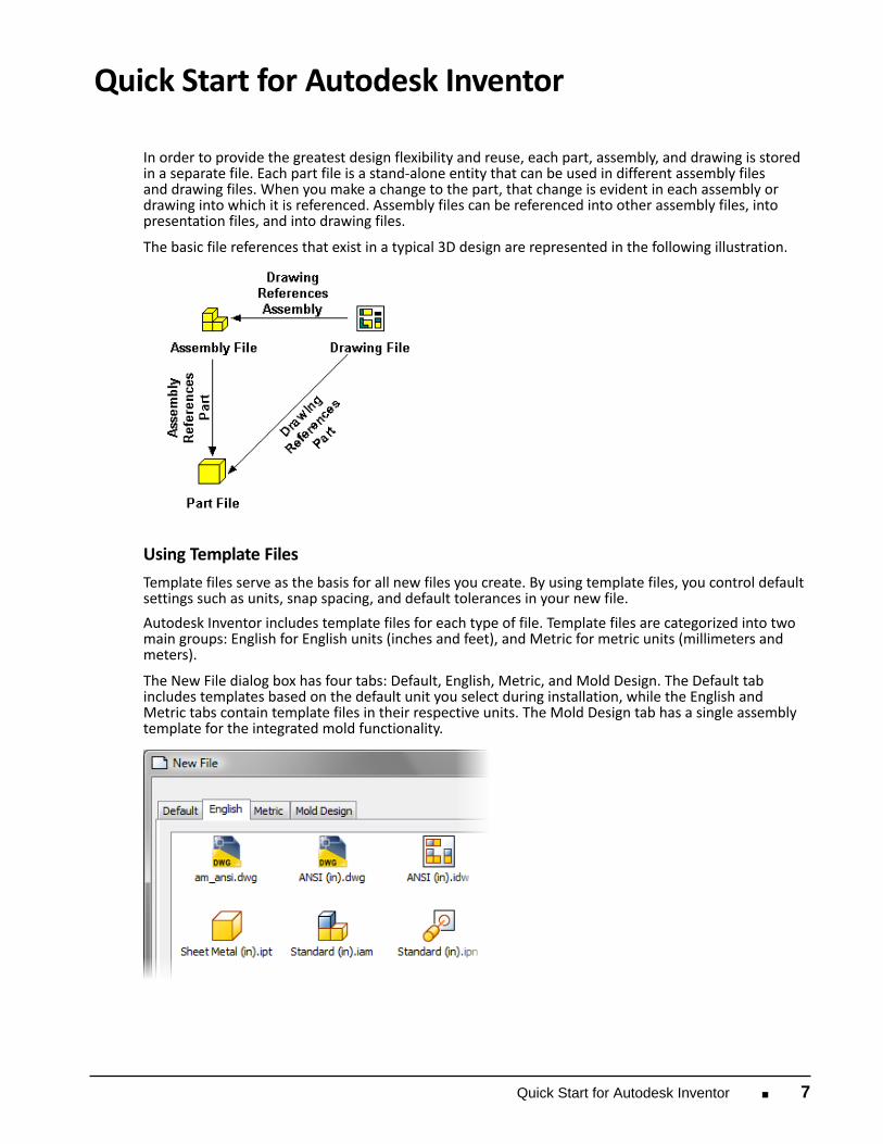
In order to provide the greatest design flexibility and reuse, each part, assembly, and drawing is storedin a separate file. Each part file is a stand-alone entity that can be used in different assembly filesand drawing files. When you make a change to the part, that change is evident in each assembly ordrawing into which it is referenced. Assembly files can be referenced into other assembly files, intopresentation files, and into drawing files. The basic file references that exist in a typical 3D design are represented in the following illustration.
Using Template Files
Template files serve as the basis for all new files you create. By using template files, you control defaultsettings such as units, snap spacing, and default tolerances in your new file.
Autodesk Inventor includes template files for each type of file. Template files are categorized into twomain groups: English for English units (inches and feet), and Metric for metric units (millimeters andmeters). The New File dialog box has four tabs: Default, English, Metric, and Mold Design. The Default tabincludes templates based on the default unit you select during installation, while the English andMetric tabs contain template files in their respective units. The Mold Design tab has a single assemblytemplate for the integrated mold functionality.

8 ■ Autodesk's VEX Robotics Unit 2: Introduction to Autodesk Inventor
Part Modeling Environment
In the part modeling environment:
■ You create and edit 3D part models.■ The interface adjusts automatically to present tools for your current task; for example, tools for
sketching or tools to create 3D features. The user interface in the part modeling environment is as shown.

Quick Start for Autodesk Inventor ■ 9
Assembly Modeling Environment
In the assembly modeling environment:
■ You build and edit 3D assembly models. The components displayed in the system are references to
external parts and subassemblies.■ You use assembly-specific tools to position and build relationships between components.■ You have access to a common set of viewing tools. The user interface in the assembly modeling environment is as shown.

10 ■ Autodesk's VEX Robotics Unit 2: Introduction to Autodesk Inventor
Presentation Environment
In the presentation environment:
■ You create exploded assembly views.■ You can record an animation of an exploded view to help document your assembly.■ The presentation file references an existing assembly.■ A common set of viewing tools is available. The user interface in the presentation environment is as shown.

Quick Start for Autodesk Inventor ■ 11
Drawing Environment
In the drawing environment:
■ You create 2D drawings of parts and assemblies.■ A drawing file references one or more parts, assemblies, or presentation files. Changes to the part
or assembly model update the associated drawing views and annotations. The user interface in the drawing environment is as shown.

12 ■ Autodesk's VEX Robotics Unit 2: Introduction to Autodesk Inventor
Context-Sensitive Tools
As you switch between environments or between tasks in a single environment, Autodesk Inventordisplays the appropriate tools and information for the current task. The ribbon automatically presentstools for the current task, and the browser displays information on the active environment.
Overview of the Browser
The browser is one of the main interface components. It is context-sensitive with the environment youuse. For example, when you work on an assembly you use the browser to present information specificto the assembly environment. While you use the part modeling environment, the browser displaysinformation that is relevant to part modeling.
Overview of the Ribbon
The ribbon is your primary interface for accessing the tools available while you design. The context-sensitive design presents the relevant tools based on the current context of your design session.For example, when you switch from assembly modeling to part modeling, the ribbon switchesautomatically to display the correct tools for the context in which you work.
Keyboard Shortcuts
On the ribbon and menus, you can use keyboard shortcuts to access tools. For example, you can enterE for Extrude. Entering the keyboard shortcut is the same as clicking the tool on the ribbon.
Keyboard shortcuts are displayed when you hover the cursor over a tool icon on the ribbon.

Quick Start for Autodesk Inventor ■ 13
Part Modeling Environment
When you are in the part modeling environment, the browser displays all features you used to createthe part. The features are listed in the order in which the model is created. The browser also displaysthe Origin folder at the top of the list, which contains the default X, Y, and Z planes, axes, and centerpoint.
You use these tools on the ribbon to create parametric features on the part.
You use the sketch tools to create 2D parametric sketches, add dimensions, and constraints.

14 ■ Autodesk's VEX Robotics Unit 2: Introduction to Autodesk Inventor
Assembly Modeling Environment
When you are in the assembly modeling environment, the browser displays all the parts you use inthe assembly. It also lists the Origin folder containing the default X, Y, and Z planes, axes, and centerpoint of the assembly.
Nested under each part, you see the assembly constraints. If you select an assembly constraint, anedit box is displayed at the bottom of the browser, enabling you to edit the offset or angle value forthe constraint.
In the assembly environment, you can use the Modeling View option in the AssemblyView drop-down list to display the part features nested under the parts instead of theassembly constraints. This is useful when performing part modeling functions in thecontext of the assembly.

Quick Start for Autodesk Inventor ■ 15
Presentation Environment
When you are in the presentation environment, the browser displays the presentation views youcreate, followed by the tweaks you use for the explosion. When you expand each tweak, you see theparts included in that tweak. You can also switch the browser mode from Tweak View to SequenceView or Assembly View.
You use the tools on the ribbon to create presentation views and tweaks, and animate geometry in thepresentation environment.

16 ■ Autodesk's VEX Robotics Unit 2: Introduction to Autodesk Inventor
Drawing Environment
In the drawing environment, the browser displays the Drawing Resource folder containing sheetformats, borders, title blocks, and sketched symbols. It also displays each sheet in the drawing alongwith the views you create for each.
You use the tools on the ribbon to create drawing views on the sheet.
In the drawing environment, on the Annotate tab, you use the tools to add reference dimensions andother annotation objects.

Quick Start for Autodesk Inventor ■ 17
Accessing Tools
The tools and commands you use are located in different areas of the user interface. In the exercises,you are given instructions to follow. You need to understand the basic areas where tools andcommands are located so that you can follow the instructions.
For your reference, the main areas of the Autodesk Inventor user interface are shown.
Application menu
Quick Access toolbar
Ribbon
Browser
Graphics window
ViewCube
Navigation toolbar

18 ■ Autodesk's VEX Robotics Unit 2: Introduction to Autodesk Inventor
Application Menu
The application menu is located at the top left of the Autodesk Inventor window.
Quick Access Toolbar
The Quick Access toolbar is located at the top of the Autodesk Inventor window.

Quick Start for Autodesk Inventor ■ 19
Ribbon
The ribbon is composed of a series of panels, which are organized into tabs labeled by task.
If you have part, assembly, and drawing files open at the same time, the ribbon changes depending onwhich window is active.

20 ■ Autodesk's VEX Robotics Unit 2: Introduction to Autodesk Inventor
The Browser
The browser is typically located on either the left or right side of the Autodesk Inventor window. Thebrowser changes depending on the type of file you are editing. For example, for parts, the browserdisplays all of the features that were used to create the part. For assemblies, the browser displays allof the parts that make up the assembly. You frequently use the browser to access parts or features.
Shortcut Menus
You frequently access shortcut menus in the graphics area of the screen. Different menus aredisplayed depending on whether you right-click a part or right-click the graphic background (the blankarea around the part). If you cannot find the command on the menu, make sure you are right-clickingin the correct area.
Some tools and commands are accessed through shortcut menus. You display a shortcut menu byclicking the right mouse button.

Quick Start for Autodesk Inventor ■ 21
Shortcut Keys
Some of the commands can be accessed by pressing a key or combination of keys instead of clicking.When you are familiar with the shortcut key for a command, you may find it faster to press a key thanto find the correct menu and click the icon. The shortcut key is listed next to the tool in the menu orpanel bar. The following image shows three commands from the ribbon. To create an extrusion, eitherclick Extrude or press E. To create a revolved feature, press R. To create a hole, press H.

22 ■ Autodesk's VEX Robotics Unit 2: Introduction to Autodesk Inventor
Exercise: Use the Design Support System In this exercise, you access Autodesk Inventorsoftware support using the Help System. This exercise illustrates how you can accessimmediate support during the design process. Thissupport includes Tutorials, Show Me Animations, andHelp Topics. Before starting the exercise, you can refer to avideo demonstration of the workflow. To view thedemonstration, navigate to the Video Demonstrationfolder for this exercise. You can pause and scroll through the video to searchfor help on how to complete a specific section.
The completed exercise
Access Autodesk Inventor Tutorials Autodesk Inventor includes several tutorials to helpyou learn the features of the software. If you wantto spend time on your own learning more aboutAutodesk Inventor, try some of the exercises in theHelp > Learning Tools > Tutorials > New Users section. 1. Start Autodesk Inventor. 2. If the Open dialog box or Help window is
displayed, close them.
3.
Click Help > Learning Tools > Tutorials.
The Autodesk Inventor Tutorial LearningResource window is displayed.
4. On the New Users tab, click Parts 1.

Quick Start for Autodesk Inventor ■ 23
5.
Review the first page.
6.
Click the Next button. Review the next fourpages.
7. Close the Autodesk Inventor Tutorials windows.
Access Show Me Animations In a design session, you work in differentenvironments such as part modeling and assemblymodeling. There are tasks in these environments thatyou may not be familiar with and require immediatehelp. Show Me Animations displays a palette ofdesign tasks that guide you through the task. 1.
Click Help.
2.
Under Basics and Tutorials > Learn Inventor,click Show Me Animations.
3. Click Inventor. 4.
Click Sketch Dimensions > Linear > Two ObjectsAnimation.

24 ■ Autodesk's VEX Robotics Unit 2: Introduction to Autodesk Inventor
5. Review the animation. 6. Close the Autodesk Inventor Help window.
Access Help Topics In this section of the exercise, you access Help using akey word, and you review an animation. 1. Click Help. 2. If required, click Show. 3. Click the Index tab. 4. Enter extrude. 5.
In the list of topics, double-click Creating.
6.
In the Topics Found dialog box, make sure thatCreate an Extruded Feature (Procedure) isselected. Click Display.
7. Scroll down to the bottom of the page. Click
Show Me How to Create a Basic Extrusion. The animation window is displayed.
8. Review the animation. Use the navigation tools
to repeat or advance the animation. 9. Close the Help window.

Quick Start for Autodesk Inventor ■ 25
Exercise: Build a Limit Switch In this exercise, you create the top case of the limitswitch from the VEX kit of parts. After you modelthe case, you change the material to plastic anddetermine the part's mass.
The completed exercise Before starting the exercise, you can refer to avideo demonstration of the workflow. To view thedemonstration, navigate to the Video Demonstrationfolder for this exercise. Double-click the HTML file tostart the video. You can pause and scroll through the video to searchfor help on how to complete a specific section.
Create a Sketch for the Base In this section of the exercise, you start a new part fileand sketch the profile of the base. 1. Make IFI_Unit2.ipj the active project. 2. On the Launch panel, click New. 3. Click the English tab. Double-click Standard
(in).ipt. 4.
On the Draw panel, click Rectangle.
5.
To sketch the rectangle:■ Click in the graphics window to set the first
corner point (1).■ Move the cursor diagonally to create a
rectangle approximately 1.5 inches long and1 inch high (2). Do not click at the secondpoint.
6.
To dimension the rectangle:■ Enter 1.246.■ Press the TAB key.■ Enter 0.728■ Press ENTER.
7. Press ESC to exit the Rectangle tool.

26 ■ Autodesk's VEX Robotics Unit 2: Introduction to Autodesk Inventor
8. Right-click in the graphics window. Click Finish
Sketch.
Extrude the Sketch In this section of the exercise, you extrude the sketchto create the base. You then add fillets to two edges. 1.
On the Create panel, click Extrude.
2.
For Distance, enter 0.337
For Dynamic Input, enter 0.337
3. On the Extrude dialog box, click the More tab.
4.
For Taper, enter -1.0 (Negative 1).
5.
Click OK.
6.
On the Modify panel, click Fillet.
7.
Select the two edges as shown.
8.
For Radius, enter 0.15

Quick Start for Autodesk Inventor ■ 27
9.
Click OK.
10. Save the file as my_limitswitch_top.ipt.
Create a Sketch for the Cutout In this section of the exercise, you extrude the cutouton the back of the part. 1.
On the ViewCube, click the top-right corner asshown.
2. On the ViewCube, click Back. 3.
On the Sketch panel, click Create 2D Sketch.
4. Select the back face of the part. 5.
On the Draw panel, click Line.
6.
Create the sketch as shown. Make sure that allthe lines are vertical or horizontal.
7.
On the Constrain panel, click Colinear.
8.
Select the line (1) as shown. Select the next line(2).
9.
Repeat the workflow for:■ The vertical lines 3 and 4.■ The short horizontal lines 5 and 6.■ The short horizontal lines 7 and 8.
10.
On the Constrain panel, click Equal.
11.
Select the short horizontal lines 1 and 2.
12.
On the Constrain panel, click Vertical.

28 ■ Autodesk's VEX Robotics Unit 2: Introduction to Autodesk Inventor
13.
Move the cursor over the center of the topedge of the part. Click when the large greendot is displayed (1). Click the midpoint on thesketch as shown (2).
Extrude the Cutout In this section of the exercise, you fully constrain thesketch by adding dimensions. You then extrude thesketch to make the cutout on the back of the part. 1.
On the Constrain panel, click Dimension.
2.
Look at the lower right of the graphics window.To fully constrain the sketch, six dimensions areneeded.
3.
Right-click in the graphics window. Click EditDimension.
4.
To place the first dimension:■ Click the top edge of the part and top edge
of the sketch to place the dimension. Nowthe Edit Dimension dialog box is displayedwithout clicking the dimension.
■ Enter 0.081. Click the check mark.
5.
Add 0.096 and 0.195 dimensions as shown.
6.
Place the dimension as shown. Do not click thecheck mark.

Quick Start for Autodesk Inventor ■ 29
7.
Move the cursor over the first 0.081 dimension.Click the dimension when the hand symbol isdisplayed.
8.
Click the check mark. The new dimensionhas an fx: prefix to indicate it is a function ofanother dimension.
9.
Repeat this workflow to place two moredimensions. The sketch is now fully constrained.
10. Press ESC to cancel the Dimension tool.
11.
On the ViewCube, click the top-right corner.
12. Press E to start the Extrude tool. 13.
Select inside the sketch as the profile.
14.
For Operation, click Cut.
15. For Distance, enter 0.258. 16.
Click OK.
17. Save the file.
30 ■ Autodesk's VEX Robotics Unit 2: Introduction to Autodesk Inventor
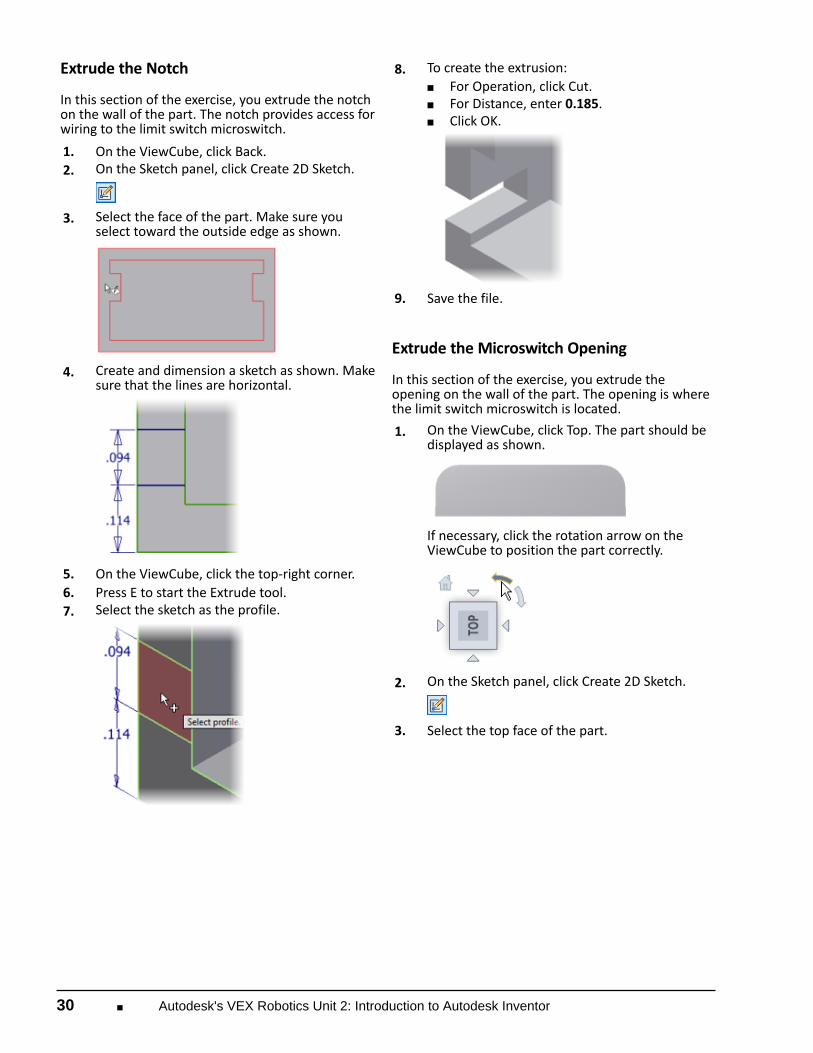
Extrude the Notch In this section of the exercise, you extrude the notchon the wall of the part. The notch provides access forwiring to the limit switch microswitch. 1. On the ViewCube, click Back. 2.
On the Sketch panel, click Create 2D Sketch.
3.
Select the face of the part. Make sure youselect toward the outside edge as shown.
4.
Create and dimension a sketch as shown. Makesure that the lines are horizontal.
5. On the ViewCube, click the top-right corner. 6. Press E to start the Extrude tool. 7.
Select the sketch as the profile.
8.
To create the extrusion:■ For Operation, click Cut.■ For Distance, enter 0.185.■ Click OK.
9. Save the file.
Extrude the Microswitch Opening In this section of the exercise, you extrude theopening on the wall of the part. The opening is wherethe limit switch microswitch is located. 1.
On the ViewCube, click Top. The part should bedisplayed as shown.
If necessary, click the rotation arrow on theViewCube to position the part correctly.
2.
On the Sketch panel, click Create 2D Sketch.
3. Select the top face of the part.

Quick Start for Autodesk Inventor ■ 31
4.
Sketch three lines as shown. When yousketch the shorter lines (1 and 2), exaggeratetheir angle to prevent a vertical, parallel, orperpendicular constraint from being applied.You apply parallel constraints after you createthe sketch.
5.
Apply parallel constraints between each ofthe short lines (1 and 2) and the adjacent partedges (3 and 4).
6. Apply a vertical constraint between the
midpoint of the horizontal line and one of thehorizontal edges so that the sketch is centeredon the face.
7.
Add 0.219 and 0.798 dimensions to the sketchas shown. Tip: Press D to start the Dimension tool.
8.
On the ViewCube, click the top-right corner.
9. Press E to start the Extrude tool. 10.
Select the sketch as the profile.
11.
To create the extrusion:■ For Operation, click Cut.■ Under Extents, select To Next from the list.
12.
Click OK.
13. Save the file.

32 ■ Autodesk's VEX Robotics Unit 2: Introduction to Autodesk Inventor
Create the Holes In this section of the exercise, you create two holes.These holes are used to assemble the limit switch. 1.
On the ViewCube, click the bottom left edge.
2. On the ViewCube, click Back. 3.
On the Sketch panel, click Create 2D Sketch.
4.
Select the face of the part as shown.
5.
On the Draw panel, click Point.
6.
Move the cursor over the midpoint of thevertical line. When the midpoint is displayed,click to place the point.
7.
On the Draw panel, click Project Geometry.
8.
Select the line on the right side of the sketch asshown.

Quick Start for Autodesk Inventor ■ 33
9.
On the Draw panel, click Point. Place a centerpoint on the midpoint of the line.
10. On the ViewCube, click the top right corner. 11. Press H to start the Hole tool. The center points
are selected automatically. 12.
Click Countersink as the hole type.
13.
Under Drill Point, click Flat.
14.
To set the hole dimensions:■ For Countersink Diameter (1), enter 0.114.■ For Hole Diameter (2), enter 0.073.
15.
Under Termination, select To from the list.
16.
Select the bottom inside face of the part.
17.
Select the Check to Terminate Feature on theExtended Face check box.
18.
Click OK.
19. Save the file.

34 ■ Autodesk's VEX Robotics Unit 2: Introduction to Autodesk Inventor
Create Two Locating Pins In this section of the exercise, you extrude twolocating pins. 1.
On the Sketch panel, click Create 2D Sketch.
2.
Select the face on the right side of the part asshown.
3. On the ViewCube, click Back. 4.
On the Draw panel, click Circle.
5.
Create a circle at the bottom left of the part.
6.
Dimension the circle as shown.
7.
Create a circle at the top right of the part.
8.
Dimension the circle as shown.
9.
On the ViewCube, click the top-right corner.The part should be displayed as shown.
10. Press E to start the Extrude tool. 11. Select the circles as the profiles.

Quick Start for Autodesk Inventor ■ 35
12.
To create the extrusion:■ For Distance, enter 0.059■ Click OK.
13. Save the file.
Add Fillets to the Part In this section of the exercise, you add fillets to thepart. 1.
On the Modify panel, click Fillet.
2.
To create the fillets:■ Select the edges of the two locating pins, 1
and 2.■ For Radius, enter 0.025.
3.
Click OK.
4.
On the Navigation toolbar, click Zoom All.
5.
On the Modify panel, click Fillet.
6.
To create the fillets:■ Select the edges. (1 and 2)■ For Radius, enter 0.031.
7.
Click OK.
8.
Create 0.030 fillets on the short vertical edges.(1 and 2) Tip: If you select the wrong edges, deselectthe edges by holding down the SHIFT key andselecting the edge.

36 ■ Autodesk's VEX Robotics Unit 2: Introduction to Autodesk Inventor
9.
Rotate the part to view the inside edges.
10.
Create 0.060 fillets on the edges. (1 and 2)
11.
Create 0.021 fillets on the edges. (1 and 2)
12.
Rotate the part to view the inside face on theopposite side of the part.
13.
Repeat the workflow from the previoussteps and add 0.060 and 0.021 fillets to theequivalent edges on the part.
14.
Rotate the part to view the cutout.
15.
On the Modify panel, click Fillet.
16.
To select the first edge set:■ Select edges 1, 2, and 3.■ For radius, enter 0.01.

Quick Start for Autodesk Inventor ■ 37
17.
In the Fillet dialog box, click Click to Add.
18.
To select the second edge set:■ Select edges 4 and 5.■ For radius, enter 0.03.
19.
Click OK.
20.
Rotate the part to view the outside of thecutout.
21.
Create 0.03 fillets on the edges. (1, 2, and 3)
22. Save the file.
Change the Material of the Limit Switch Top In this section of the exercise, you change thematerial of the limit switch top to ABS plastic. 1. On the ViewCube, click Home. 2.
On the Manage tab, Styles and Standardspanel, click Styles Editor.
3.
Expand Material. Click ABS Plastic.
4.
For color, select Red.
5. Click Save. 6. Click Done. 7. In the browser, right-click my_limit_switch.ipt.
Click iProperties. 8. Click the Physical tab. 9. For Material, select ABS Plastic. 10. Click Apply. Note the updated properties of the
part, such as Mass, Area, and Volume.

38 ■ Autodesk's VEX Robotics Unit 2: Introduction to Autodesk Inventor
11.
Click Close.
12. Save the file. 13. Close the file.

Quick Start for Autodesk Inventor ■ 39
Exercise: Assemble a Limit Switch In this exercise, you assemble the three parts of thelimit switch.
The completed exercise Before starting the exercise, you can refer to avideo demonstration of the workflow. To view thedemonstration, navigate to the Video Demonstrationfolder for this exercise. Double-click the HTML file tostart the video. You can pause and scroll through the video to searchfor help on how to complete a specific section.
Place the Microswitch in the Assembly In this section of the exercise, you create a newassembly file, and then place two parts of the limitswitch in the assembly. 1. Make IFI_Unit2.ipj the active project. 2. On the Launch panel, click New. 3. Click the English tab. Double-click Standard
(in).iam. 4.
On the Component panel, click Place.
5.
To place the first part:■ Select LIMIT-SWITCH-MICROSWITCH.ipt.■ Click Open.■ Right-click in the graphics window. Click
Done.
Note: The first part in the assembly isgrounded. All degrees of freedom are removed.In the browser, the part has a thumbtack iconto indicate it is grounded.
6.
On the Component panel, click Place.
7.
To place the second part:■ Select LIMIT-SWITCH-BOTTOM.ipt.■ Click Open.■ Click to place an occurrence of the
component.■ Right-click in the graphics window. Click
Done.
8. In the browser, expand the LIMIT-SWITCH-
MICROSWITCH:1 listing.

40 ■ Autodesk's VEX Robotics Unit 2: Introduction to Autodesk Inventor
9.
Right-click Work Plane1. Click Visibility to turnon visibility.
10. Repeat this workflow for LIMIT-SWITCH-
BOTTOM:1. 11.
On the Position panel, click Constrain.
12.
To place the constraint:■ Select the edge of the workplane on the
LIMIT-SWITCH-MICROSWITCH.■ Select the edge of the workplane on the
LIMIT-SWITCH-BOTTOM.■ Click OK.
13. Using the same workflow from the previous
steps, turn off the visibility of the work planes. 14. Save the file as my_limitswitch.iam.
Assemble the Parts 1. On the ViewCube, click Top. 2.
On the ViewCube, click the top right corner.
3.
Drag the LIMIT-SWITCH-BOTTOM away fromthe assembly.
4.
On the Position panel, click Constrain.
5.
Select the face of the LIMIT-SWITCH-BOTTOMas shown.

Quick Start for Autodesk Inventor ■ 41
6.
Rotate the assembly. Select the face of theLIMIT-SWITCH-MICROSWITCH.
7.
Click OK.
8. Drag the LIMIT-SWITCH-BOTTOM. It is free to
move up and down. 9.
On the Position panel, click Move.
10.
Drag the LIMIT-SWITCH-BOTTOM away fromthe assembly.
11.
On the Position panel, click Constrain.
12.
Select the edge of LIMIT-SWITCH-BOTTOM.Make sure the edge is highlighted, not the face.
13.
Select the edge of LIMIT-SWITCH-BOTTOM.
14.
Click OK.
15. Drag the LIMIT-SWITCH-BOTTOM. It cannot
move. All degrees of freedom have beenremoved.
16. Save the file.

42 ■ Autodesk's VEX Robotics Unit 2: Introduction to Autodesk Inventor
Place the Top of the Limit Switch in theAssembly In this section of the exercise, you place anoccurrence of the top part of the limit switch in theassembly. 1. On the ViewCube, click Home. 2.
On the Component panel, click Place.
3.
To place the third part:■ Select LIMIT-SWITCH-TOP.ipt.■ Click Open.■ Click to place an occurrence of the
component.■ Right-click in the graphics window. Click
Done.
4.
Zoom into the area around the locating pinand hole. If the hole is not visible, drag LIMIT-SWITCH-TOP so that the hole is visible.
5.
On the Position panel, click Constrain.
6.
Under Type, click Insert.
7.
Select the edge of the locating hole.
8.
Rotate the assembly. Select the edge of thelocating pin.
9. Click OK. 10.
Rotate the assembly to view the opposite sideof LIMIT-SWITCH-TOP.
11.
On the Position panel, click Move.

Quick Start for Autodesk Inventor ■ 43
12.
Drag the LIMIT-SWITCH-TOP away from theassembly.
13.
On the Position panel, click Constrain.
14.
Place an insert constraint between the holeand the locating pin.
15.
Click OK.
16.
On the ViewCube, click Home.
17. Save the file. 18. Close the file.

44 ■ Autodesk's VEX Robotics Unit 2: Introduction to Autodesk Inventor
Exercise: Create a Drawing of the Limit Switch In this exercise, you create a drawing of the limitswitch. You also add balloons and a parts list to thedrawing.
The completed exercise Before starting the exercise, you can refer to avideo demonstration of the workflow. To view thedemonstration, navigate to the Video Demonstrationfolder for this exercise. Double-click the HTML file tostart the video. You can pause and scroll through the video to searchfor help on how to complete a specific section.
Create a New Drawing In this section of the exercise, you create a newdrawing file, rename the sheet, and insert a differenttitle block. 1. Make IFI_Unit2.ipj the active project. 2. On the Launch panel, click New. 3. Click the English tab. Double-click ANSI (in).idw. 4. In the browser, right-click Sheet:1. Click Edit
Sheet.
5.
In the Edit Sheet dialog box:■ For Name, enter Assembly.■ From the Size list, select A.■ Click OK.
6.
In the browser, right-click ANSI - Large. ClickDelete.
7.
In the browser, expand Drawing Resources >Title Blocks. Right-click ANSI A. Click Insert.
8. Save the file as my_limitswitch.idw.

Quick Start for Autodesk Inventor ■ 45
Create the Drawing Views In this section of the exercise, you create four views ofthe assembly. 1.
On the Create panel, click Base.
2.
To create the base view:■ Click Open an Existing File.■ Select LIMIT-SWITCH.iam.■ Click Open.■ Under Orientation, click Top.■ Click in the sheet to place the view.
3.
To create the projected views:■ Move the preview upward.■ Click to place the top view.■ Move the cursor to the right of the base
view.■ Click to place the right side view.■ Move the cursor up and to the right of the
base view.■ Click to place an isometric view.■ Right-click in the sheet. Click Create.
4. Move the cursor over the base view to display
the red dotted line. Right-click in the view. ClickEdit View.
5. On the Display Options tab, select the Tangent
Edges check box to turn on tangent edgesdisplay.
6. Click OK. The edges of the fillets are displayed. 7. Move the cursor over the isometric view to
display the red dotted line. Right-click in theview. Click Edit View.
8.
Under Style, click Shaded.
9.
Click OK.
10. Save the file.

46 ■ Autodesk's VEX Robotics Unit 2: Introduction to Autodesk Inventor
Add Balloons and a Parts List In this section of the exercise, you add balloons and aparts list. 1.
On the Annotate tab, Table panel, click thearrow below Balloon. Click Auto Balloon.
2.
To add the balloons:■ Select the front view.■ Right-click the front view. Click Select All.■ Right-click in the graphics window. Click
Continue.■ In the Auto Balloon dialog box, under
Placement, click Around.■ Click to place the balloons.■ Click OK.■ If a dialog box is displayed, click OK.
3.
On the Table panel, click Parts List.
4.
To create the parts list:■ Select the front view.■ Click OK.■ Click to place the parts list over the title
block.
5. Right-click the parts list. Click Edit Parts List. 6.
Click Column Chooser.
7. To delete the Description column:
■ Under Selected Properties, selectDescription.
■ Click Remove.■ Click OK.
8. To edit the column width:
■ Right-click the ITEM column header. ClickColumn Width.
■ For Column Width, enter 0.5.■ Click OK.
9. Repeat this workflow to set the column width
for QTY to 0.5 and PART NUMBER to 2.5. 10.
Click OK to close the Parts List dialog box. Ifnecessary, drag the parts list to its originallocation.
11. If necessary, move the drawing views away
from the parts list. 12. Save the file.

Quick Start for Autodesk Inventor ■ 47
Edit the Properties In this section of the exercise, you edit the drawingproperties. 1. In the browser, right-click my_limitswitch. Click
iProperties. 2.
To edit the Summary Properties:■ Click the Summary tab.■ For Title, enter LIMIT SWITCH.■ For Author, enter your name.■ For Company, enter your school name.■ Click OK.
3. Save the file. 4. Close the file.