Embed Size (px)
DESCRIPTION
Showcase 3D visualization and 3D presentation software provides easy-to-use presentation and design exploration tools for architects, designers, engineers, and marketing professionals. Quickly transform 3D CAD models into interactive walk-throughs and presentations, so that you can evaluate aesthetic and design alternatives in real time with peers, constituents, and customersIn this class, we will look at using Autodesk Showcase to visualize an Autodesk InventorMechanical assembly. We will walk through steps to author and view the Mechanical Assembly in a real time environment
Citation preview

12/2/2008 - 1:15 pm - 2:45 pm Room:Murano 3303 (MSD)
Autodesk® Showcase™ Hands-On for Engineers
In this class, we will look at using Autodesk Showcase to visualize an Autodesk Inventor® Mechanical assembly. We will walk through steps to author and view the Mechanical Assembly in a real time environment.
ML111-2L
About the Speaker:
Chris Hall - Technical Marketing Manager, AutodeskMike Prom (Assistant); Helge Brettschneider (Assistant); 1 Lab Assist (Assistant)and
Chris Hall is currently a Technical Marketing Manager for Autodesk, supporting the Autodesk ID Products.
Stay Connect with AU all year at www.autodeskuniversity.comr

ML111-2L Autodesk Showcase Hands-On for Engineers
3
Autodesk Showcase software addresses the important issue of decision-making on digital
prototypes. It enables designers and engineers to create accurate, realistic imagery from 3D
CAD data to not only convey form and function, but also create environmental context to
communicate brand character. Showcase helps users present and review models in an
environment in which team members can make reliable decisions locally and via remote
sessions—resulting in an efficient and economical design review process.
Importing data into Showcase (Process)
1. Select File-> Import Models
Change selection to Autodesk Inventor files (*.iam,*.ipt)
Import Inventor assembly BevelGear.iam
2. Set the Conversion settings to 05-Default-1LOD-VeryHigh
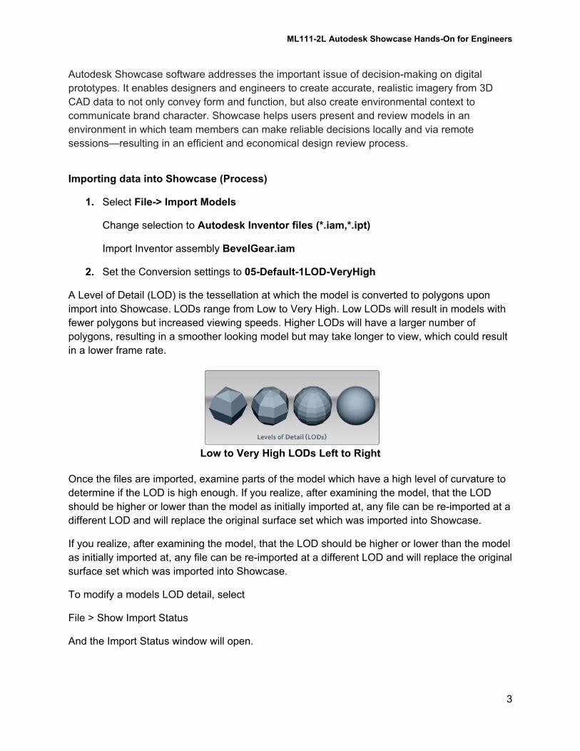
A Level of Detail (LOD) is the tessellation at which the model is converted to polygons upon
import into Showcase. LODs range from Low to Very High. Low LODs will result in models with
fewer polygons but increased viewing speeds. Higher LODs will have a larger number of
polygons, resulting in a smoother looking model but may take longer to view, which could result
in a lower frame rate.
Low to Very High LODs Left to Right
Once the files are imported, examine parts of the model which have a high level of curvature to
determine if the LOD is high enough. If you realize, after examining the model, that the LOD
should be higher or lower than the model as initially imported at, any file can be re-imported at a
different LOD and will replace the original surface set which was imported into Showcase.
If you realize, after examining the model, that the LOD should be higher or lower than the model
as initially imported at, any file can be re-imported at a different LOD and will replace the original
surface set which was imported into Showcase.
To modify a models LOD detail, select
File > Show Import Status
And the Import Status window will open.
ML111-2L Autodesk Showcase Hands-On for Engineers
4
Select the component that needs to be updated. The geometry will highlight along with the
name of the selected component name in the Status import window.
With the part to be updated identified, RMB on the Conversion setting of the selected Source file
and select the desired LOD.
Once the selected, the Conversion settings will update. The Conversion status will change to
needs update. Simply click on the needs update and the source file will be re-imported at the
selected LOD.
3. With import geometry selected choose Edit->Model Settings… select +Y
4. Set a Home View = View > Set Home View
Navigating your scene
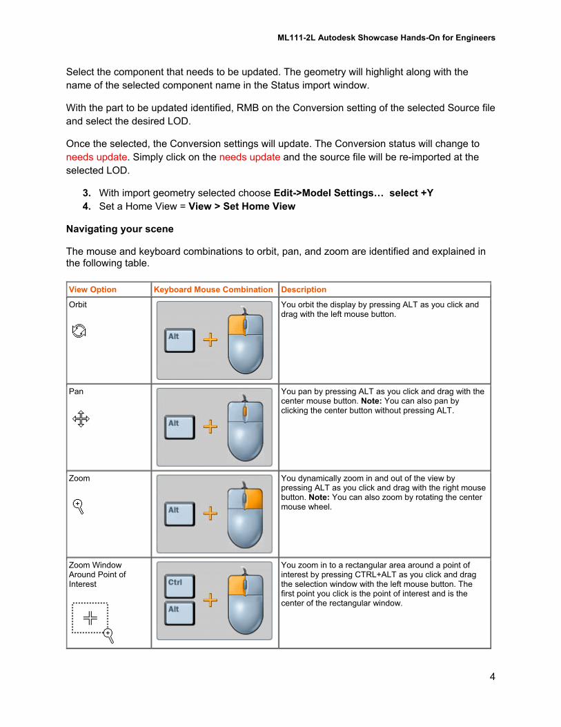
The mouse and keyboard combinations to orbit, pan, and zoom are identified and explained in the following table.
View Option Keyboard Mouse Combination Description
Orbit You orbit the display by pressing ALT as you click and drag with the left mouse button.
Pan You pan by pressing ALT as you click and drag with the center mouse button. Note: You can also pan by clicking the center button without pressing ALT.
Zoom You dynamically zoom in and out of the view by pressing ALT as you click and drag with the right mouse button. Note: You can also zoom by rotating the center mouse wheel.
Zoom Window Around Point of Interest
You zoom in to a rectangular area around a point of interest by pressing CTRL+ALT as you click and drag the selection window with the left mouse button. The first point you click is the point of interest and is the center of the rectangular window.
ML111-2L Autodesk Showcase Hands-On for Engineers
5
View Option Keyboard Mouse Combination Description
Set Point of Interest and Center
You set a new point of interest and have the view pan so that point is in the center of the screen by pressing CTRL+ALT as you click and drag over the location on the geometry with the left mouse button.
Set Point of Interest and Center
You set a new point of interest without having the view automatically pan by pressing ALT as you click and drag the location on the geometry with the left mouse button.
Preparing your Scene
5. Select Scene -> Organizer
Scroll through the list and select the following parts:
Bevel Gear_iam.apf:BG-P-001:1
Bevel Gear_iam.apf:BG-P-004:1
Bevel Gear_iam.apf:BG-P-003:2
Bevel Gear_iam.apf:BG-P-002:1
Select -> Hide
6. Hit the “E” Key on your keyboard to bring up the Environments selection
Select: ID Speed
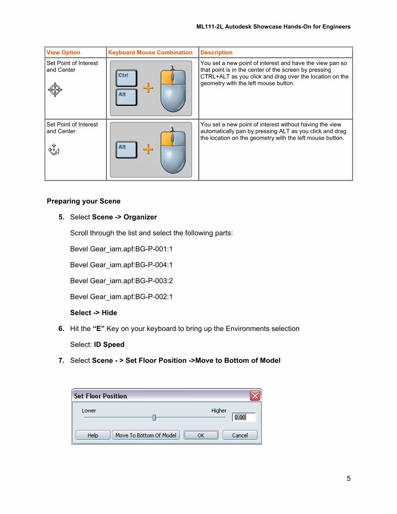
7. Select Scene - > Set Floor Position ->Move to Bottom of Model
ML111-2L Autodesk Showcase Hands-On for Engineers
6
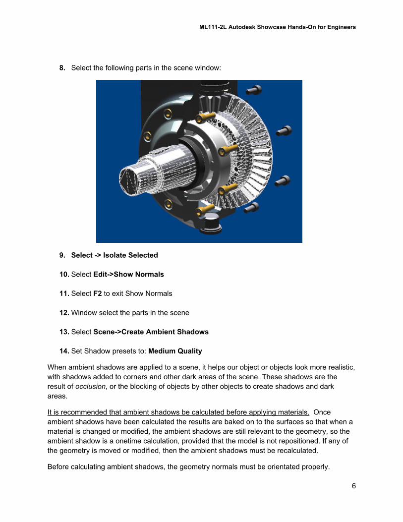
8. Select the following parts in the scene window:
9. Select -> Isolate Selected
10. Select Edit->Show Normals
11. Select F2 to exit Show Normals
12. Window select the parts in the scene
13. Select Scene->Create Ambient Shadows
14. Set Shadow presets to: Medium Quality
When ambient shadows are applied to a scene, it helps our object or objects look more realistic,
with shadows added to corners and other dark areas of the scene. These shadows are the
result of occlusion, or the blocking of objects by other objects to create shadows and dark
areas.
It is recommended that ambient shadows be calculated before applying materials. Once
ambient shadows have been calculated the results are baked on to the surfaces so that when a
material is changed or modified, the ambient shadows are still relevant to the geometry, so the
ambient shadow is a onetime calculation, provided that the model is not repositioned. If any of
the geometry is moved or modified, then the ambient shadows must be recalculated.
Before calculating ambient shadows, the geometry normals must be orientated properly.

ML111-2L Autodesk Showcase Hands-On for Engineers
7
15. Select File -> Open Scene
Select Bevel Gear Ambient Baked.zip
16. Select Scene -> Show Ambient Shadows Only
Select the same command above to turn off Ambient Shadows
17. Select Material->Replace Imported Materials…
Use the following selections:
18. Select all of the cut surfaces and select the “M” key and apply Plastic -> Red Matte
Imported�Materials� Scene�materials�RenderStyle_1� Metal::Brushed�Metal�RenderStyle_2� Metal::Brushed�Metal�RenderStyle_3� Plastic::White�Matte�RenderStyle_4� Metal::Brushed�Metal�RenderStyle_5� Metal::Brushed�Metal�RenderStyle_6� Car�Paint::Black�RenderStyle_7� Metal::Aluminum�RenderStyle_8� Metal::Aluminum�RenderStyle_9� Metal::Aluminum�RenderStyle_10� Metal::Aluminum�RenderStyle_11� Car�Paint::Orange�RenderStyle_12� Metal::Brushed�Metal�RenderStyle_13� Metal::Brake�Metal�RenderStyle_14� Metal::Aluminum�RenderStyle_15� Car�Paint::Black�RenderStyle_16� Metal::Brake�Metal�RenderStyle_17� Metal::Aluminum�
ML111-2L Autodesk Showcase Hands-On for Engineers
8
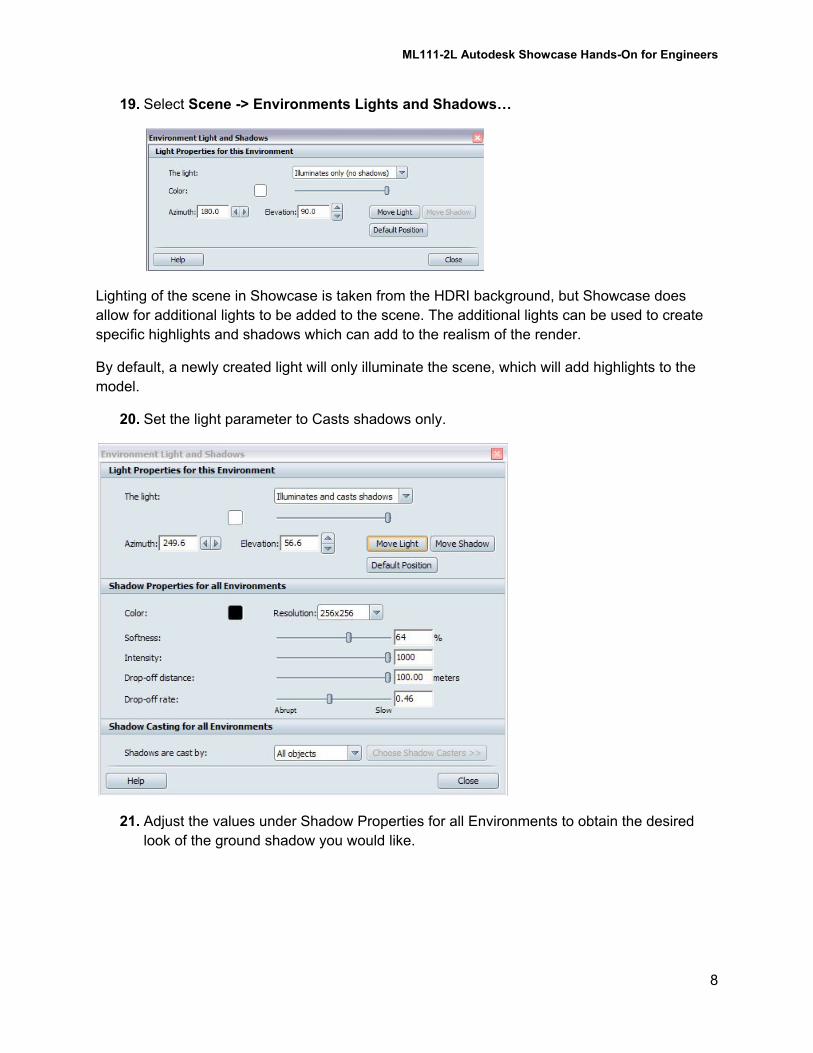
19. Select Scene -> Environments Lights and Shadows…
Lighting of the scene in Showcase is taken from the HDRI background, but Showcase does
allow for additional lights to be added to the scene. The additional lights can be used to create
specific highlights and shadows which can add to the realism of the render.
By default, a newly created light will only illuminate the scene, which will add highlights to the
model.
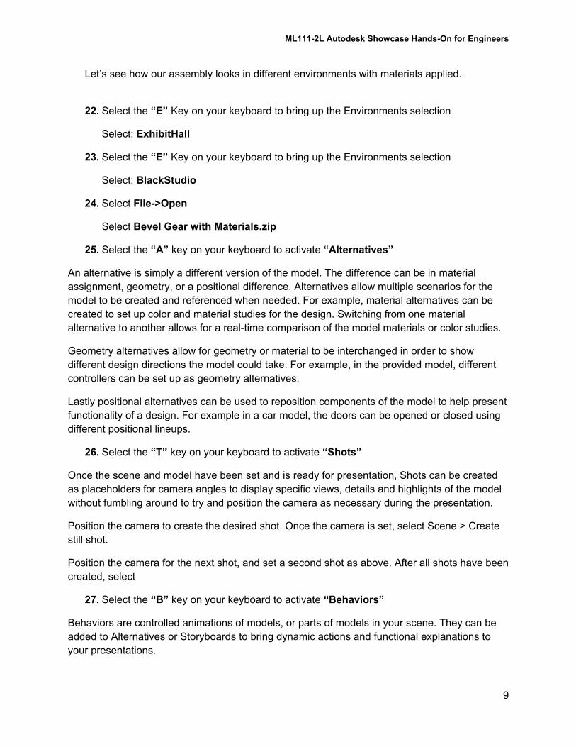
20. Set the light parameter to Casts shadows only.
21. Adjust the values under Shadow Properties for all Environments to obtain the desired
look of the ground shadow you would like.
ML111-2L Autodesk Showcase Hands-On for Engineers
9
Let’s see how our assembly looks in different environments with materials applied.
22. Select the “E” Key on your keyboard to bring up the Environments selection
Select: ExhibitHall
23. Select the “E” Key on your keyboard to bring up the Environments selection
Select: BlackStudio
24. Select File->Open
Select Bevel Gear with Materials.zip
25. Select the “A” key on your keyboard to activate “Alternatives”
An alternative is simply a different version of the model. The difference can be in material
assignment, geometry, or a positional difference. Alternatives allow multiple scenarios for the
model to be created and referenced when needed. For example, material alternatives can be
created to set up color and material studies for the design. Switching from one material
alternative to another allows for a real-time comparison of the model materials or color studies.
Geometry alternatives allow for geometry or material to be interchanged in order to show
different design directions the model could take. For example, in the provided model, different
controllers can be set up as geometry alternatives.
Lastly positional alternatives can be used to reposition components of the model to help present
functionality of a design. For example in a car model, the doors can be opened or closed using
different positional lineups.
26. Select the “T” key on your keyboard to activate “Shots”
Once the scene and model have been set and is ready for presentation, Shots can be created
as placeholders for camera angles to display specific views, details and highlights of the model
without fumbling around to try and position the camera as necessary during the presentation.
Position the camera to create the desired shot. Once the camera is set, select Scene > Create
still shot.
Position the camera for the next shot, and set a second shot as above. After all shots have been
created, select
27. Select the “B” key on your keyboard to activate “Behaviors”
Behaviors are controlled animations of models, or parts of models in your scene. They can be
added to Alternatives or Storyboards to bring dynamic actions and functional explanations to
your presentations.
ML111-2L Autodesk Showcase Hands-On for Engineers
10
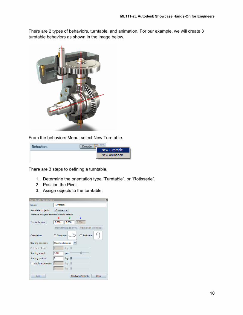
There are 2 types of behaviors, turntable, and animation. For our example, we will create 3
turntable behaviors as shown in the image below.
From the behaviors Menu, select New Turntable.
There are 3 steps to defining a turntable.
1. Determine the orientation type “Turntable”, or “Rotisserie”.
2. Position the Pivot.
3. Assign objects to the turntable.
ML111-2L Autodesk Showcase Hands-On for Engineers
11
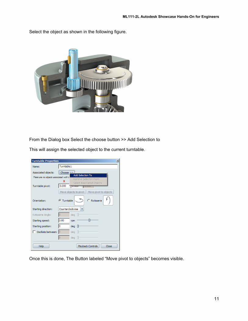
Select the object as shown in the following figure.
From the Dialog box Select the choose button >> Add Selection to
This will assign the selected object to the current turntable.
Once this is done, The Button labeled “Move pivot to objects” becomes visible.
ML111-2L Autodesk Showcase Hands-On for Engineers
12
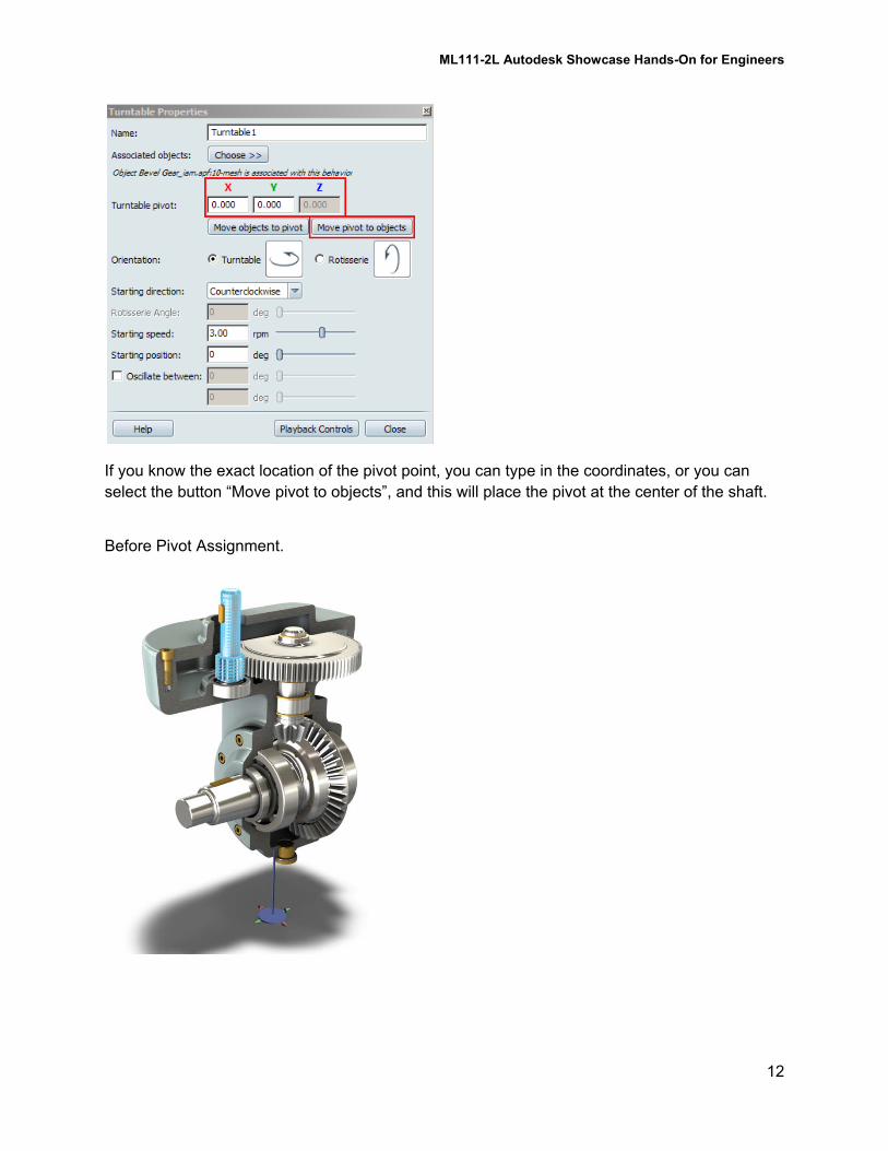
If you know the exact location of the pivot point, you can type in the coordinates, or you can
select the button “Move pivot to objects”, and this will place the pivot at the center of the shaft.
Before Pivot Assignment.
ML111-2L Autodesk Showcase Hands-On for Engineers
13
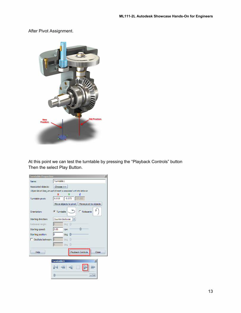
After Pivot Assignment.
At this point we can test the turntable by pressing the “Playback Controls” button
Then the select Play Button.
ML111-2L Autodesk Showcase Hands-On for Engineers
14
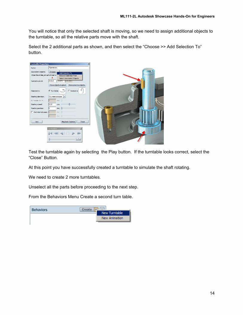
You will notice that only the selected shaft is moving, so we need to assign additional objects to
the turntable, so all the relative parts move with the shaft.
Select the 2 additional parts as shown, and then select the “Choose >> Add Selection To”
button.
Test the turntable again by selecting the Play button. If the turntable looks correct, select the
“Close” Button.
At this point you have successfully created a turntable to simulate the shaft rotating.
We need to create 2 more turntables.
Unselect all the parts before proceeding to the next step.
From the Behaviors Menu Create a second turn table.
ML111-2L Autodesk Showcase Hands-On for Engineers
15
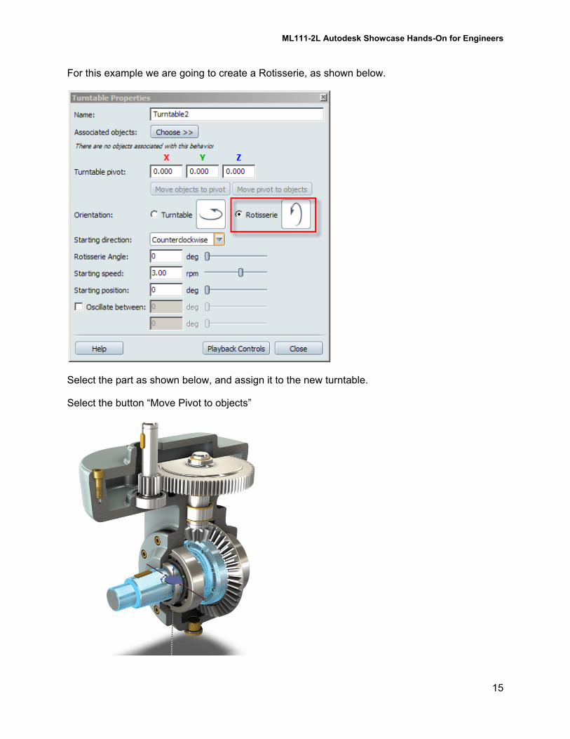
For this example we are going to create a Rotisserie, as shown below.
Select the part as shown below, and assign it to the new turntable.
Select the button “Move Pivot to objects”
ML111-2L Autodesk Showcase Hands-On for Engineers
16
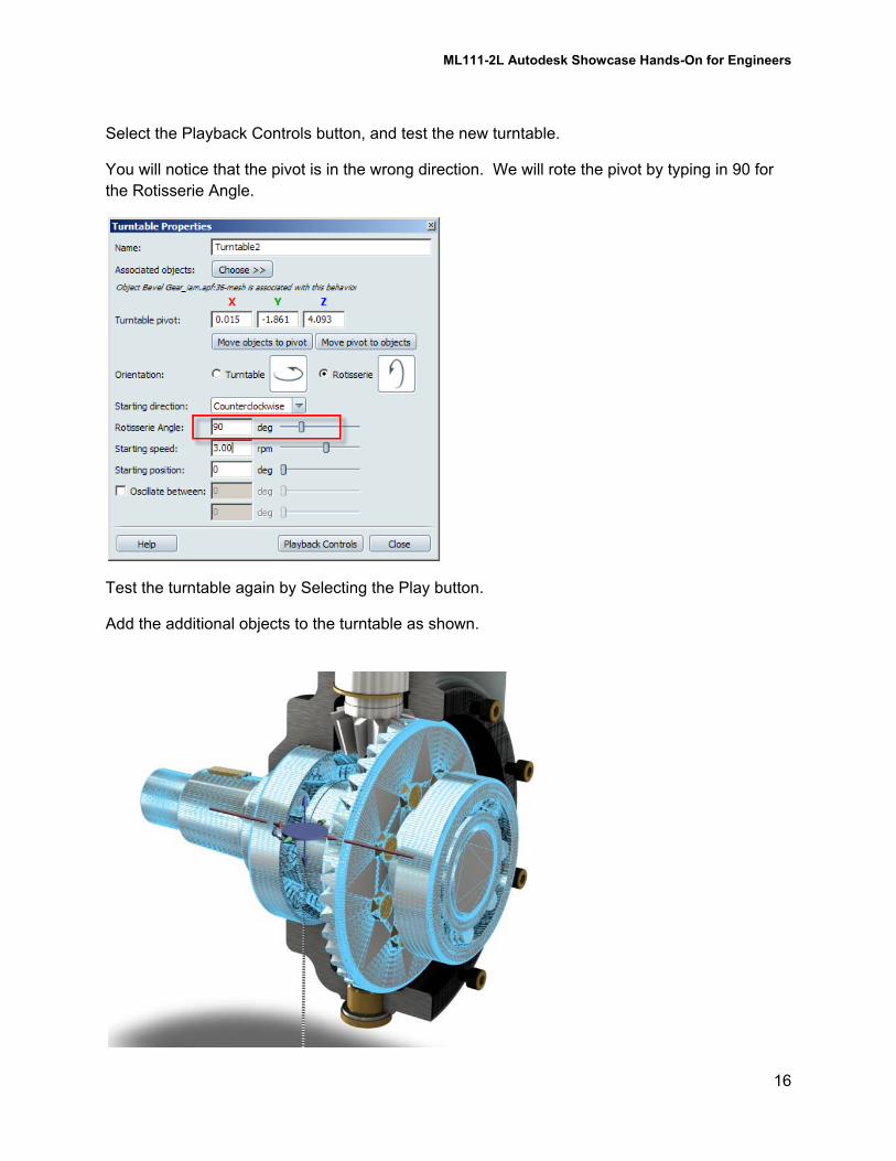
Select the Playback Controls button, and test the new turntable.
You will notice that the pivot is in the wrong direction. We will rote the pivot by typing in 90 for
the Rotisserie Angle.
Test the turntable again by Selecting the Play button.
Add the additional objects to the turntable as shown.
ML111-2L Autodesk Showcase Hands-On for Engineers
17
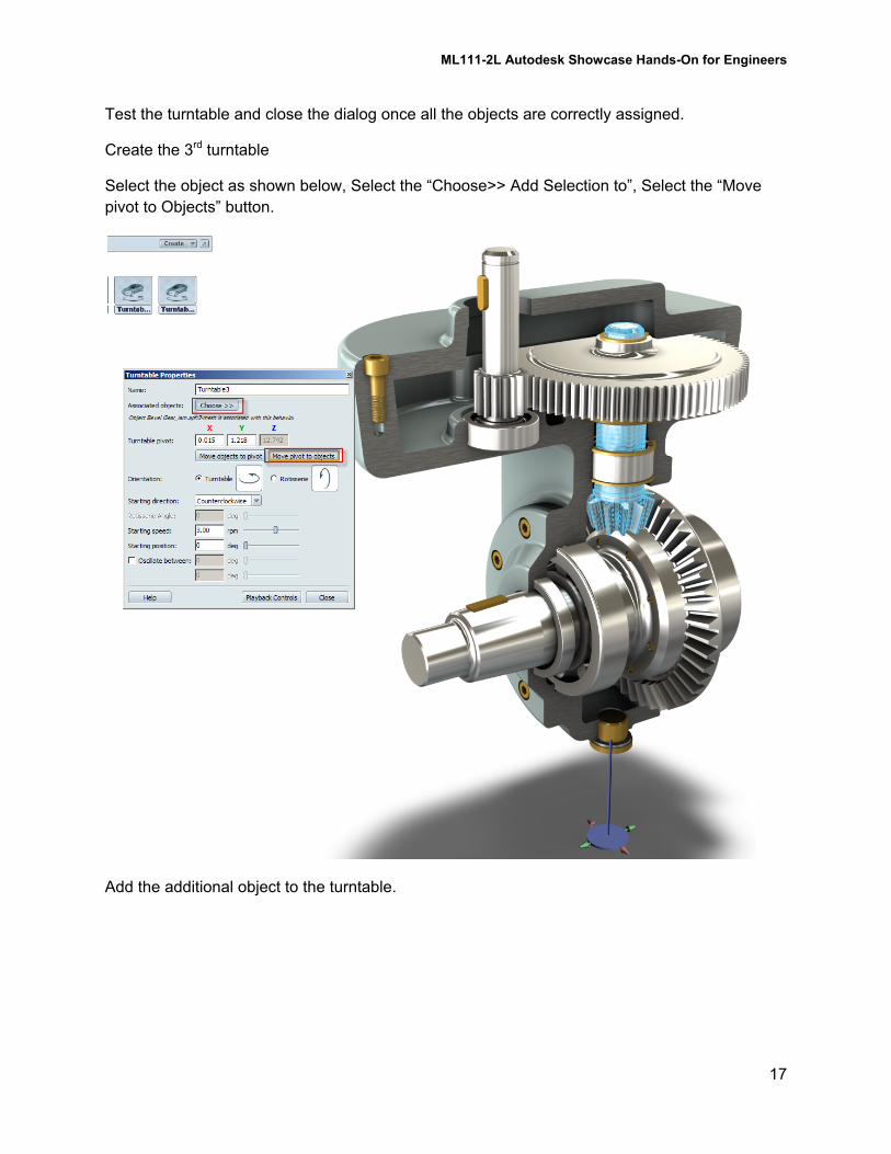
Test the turntable and close the dialog once all the objects are correctly assigned.
Create the 3rd turntable
Select the object as shown below, Select the “Choose>> Add Selection to”, Select the “Move
pivot to Objects” button.
Add the additional object to the turntable.
ML111-2L Autodesk Showcase Hands-On for Engineers
18
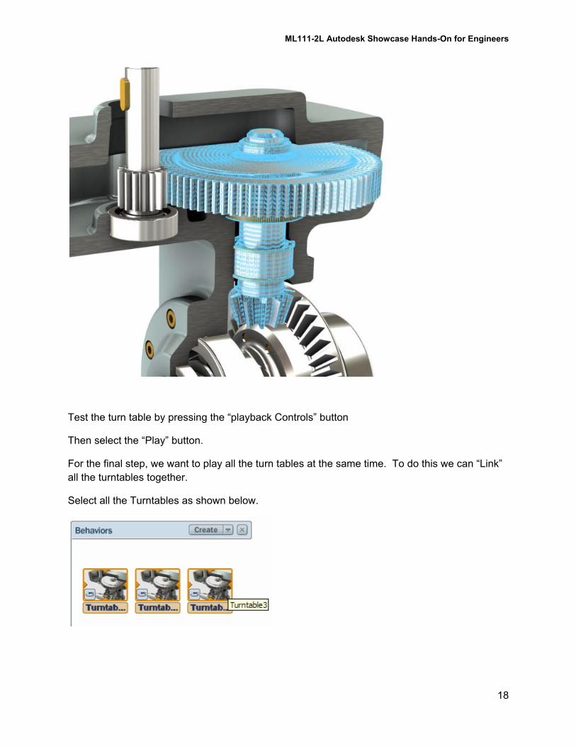
Test the turn table by pressing the “playback Controls” button
Then select the “Play” button.
For the final step, we want to play all the turn tables at the same time. To do this we can “Link”
all the turntables together.
Select all the Turntables as shown below.

ML111-2L Autodesk Showcase Hands-On for Engineers
19
Perform a Right Mouse click and choose the “Link Selected Behaviors” option.
Test the Turntable by turning on the Multiple turntable play dialog
ML111-2L Autodesk Showcase Hands-On for Engineers
20
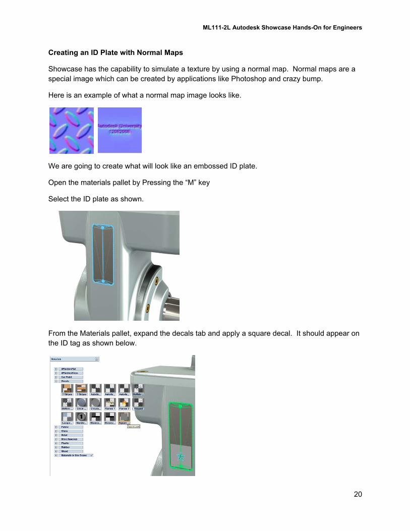
Creating an ID Plate with Normal Maps
Showcase has the capability to simulate a texture by using a normal map. Normal maps are a
special image which can be created by applications like Photoshop and crazy bump.
Here is an example of what a normal map image looks like.
We are going to create what will look like an embossed ID plate.
Open the materials pallet by Pressing the “M” key
Select the ID plate as shown.
From the Materials pallet, expand the decals tab and apply a square decal. It should appear on
the ID tag as shown below.
ML111-2L Autodesk Showcase Hands-On for Engineers
21
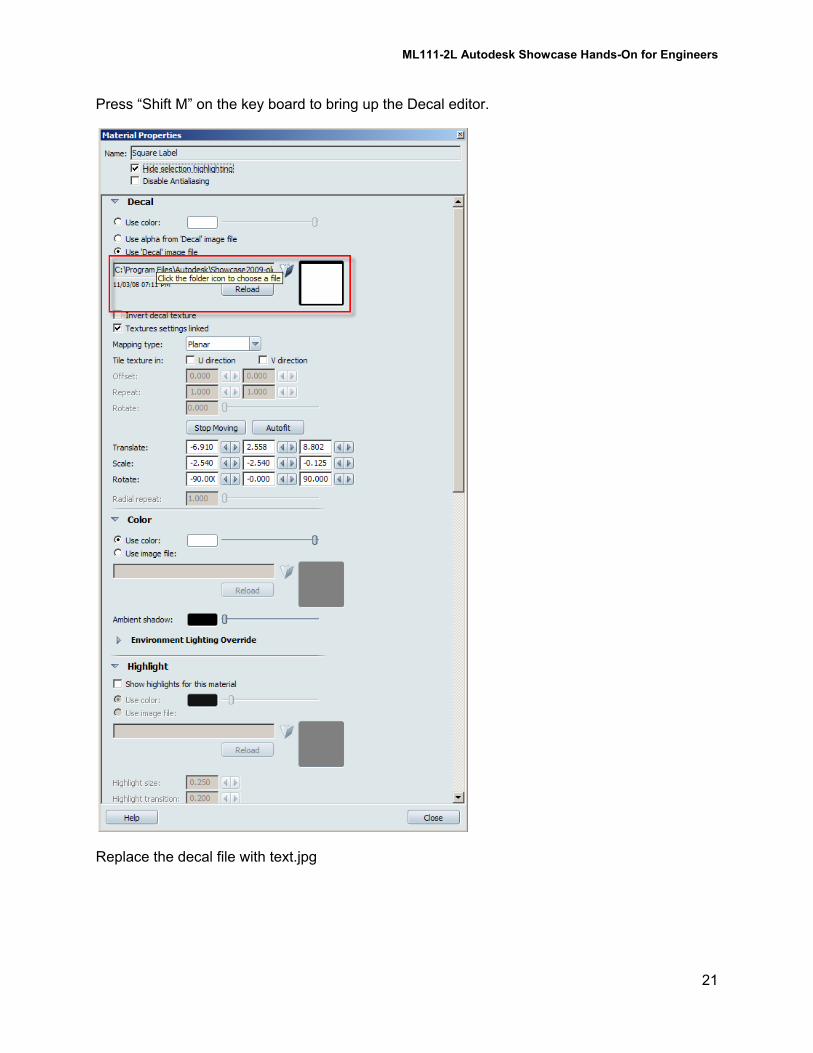
Press “Shift M” on the key board to bring up the Decal editor.
Replace the decal file with text.jpg
ML111-2L Autodesk Showcase Hands-On for Engineers
22
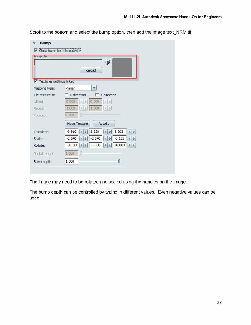
Scroll to the bottom and select the bump option, then add the image text_NRM.tif
The image may need to be rotated and scaled using the handles on the image.
The bump depth can be controlled by typing in different values. Even negative values can be
used.
ML111-2L Autodesk Showcase Hands-On for Engineers
23
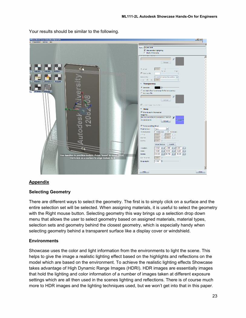
Your results should be similar to the following.
Appendix
Selecting Geometry
There are different ways to select the geometry. The first is to simply click on a surface and the
entire selection set will be selected. When assigning materials, it is useful to select the geometry
with the Right mouse button. Selecting geometry this way brings up a selection drop down
menu that allows the user to select geometry based on assigned materials, material types,
selection sets and geometry behind the closest geometry, which is especially handy when
selecting geometry behind a transparent surface like a display cover or windshield.
Environments
Showcase uses the color and light information from the environments to light the scene. This
helps to give the image a realistic lighting effect based on the highlights and reflections on the
model which are based on the environment. To achieve the realistic lighting effects Showcase
takes advantage of High Dynamic Range Images (HDRI). HDR images are essentially images
that hold the lighting and color information of a number of images taken at different exposure
settings which are all then used in the scenes lighting and reflections. There is of course much
more to HDR images and the lighting techniques used, but we won’t get into that in this paper.
ML111-2L Autodesk Showcase Hands-On for Engineers
24
Showcase includes several pre-created environments which can be selected and dropped into
the scene, to which adjustments can be made to control the lighting and sizing of the
environment.
It may be necessary to set the floor position of the environment once it’s been brought in.
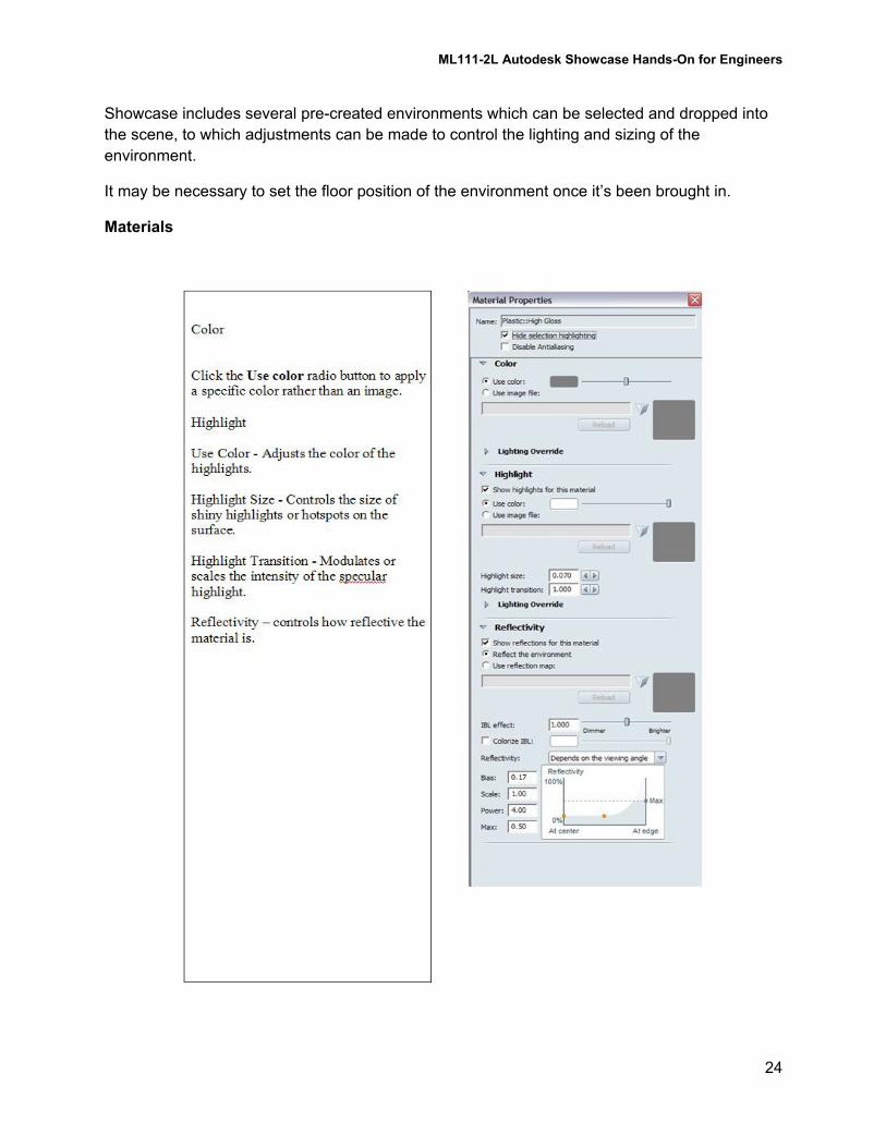
Materials