Embed Size (px)
DESCRIPTION
PPT for Robot structures
Citation preview
Autodesk Robot Structural Analysis
MAGEMBE,K
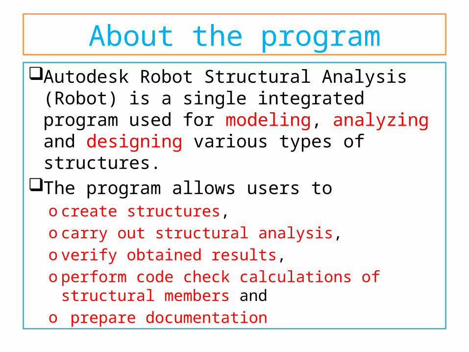
About the programAutodesk Robot Structural Analysis (Robot) is a
single integrated program used for modeling, analyzing and designing various types of structures.
The program allows users to o create structures, o carry out structural analysis, o verify obtained results, o perform code check calculations of structural
members and o prepare documentation
About the program - 2Robot – key features
o Linear, nonlinear and dynamic (modal, spectral, seismic, time history, push over, P-Delta, buckling deformation, plasticity) structure analysis
oworking in a multilingual environment (15 languages independently set to user interface, designing and calculation notes) �
o working in a multinational environment - designing according to over 50 design codes
About the program - 3o frames, plates and shells, plus a powerful GUI
modeler and mesher allows the user to define virtually any shape or configuration of structure – you analyze the true structure geometry
o quality bi-directional integration with Revit Structure, plus integration through IFC, CIS2 etc.
o an open API to allow the user to interface their own applications for pre and/or post processing
Robot modulesRobot is a single product with many functions
and a common user enviroment.At launch, Robot presents a window of
options to either open an existing structure or to enter one of the design modules. There appears the dialog, where:o the existing structure project can be selected
(Projects option):oone of recently edited projects can be indicatedo a project saved on disc can be selected (Open project
option
Robot modules - 2owork on a new project can be commenced (New
Project option)o one of default structure types can be indicated
(building, plate, shell or frame 3D) of recently edited projects can be indicated
o a new project type can be selected (More option).
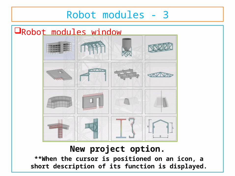
Robot modules - 3Robot modules window
New project option. **When the cursor is positioned on an icon, a short description of its function is displayed.
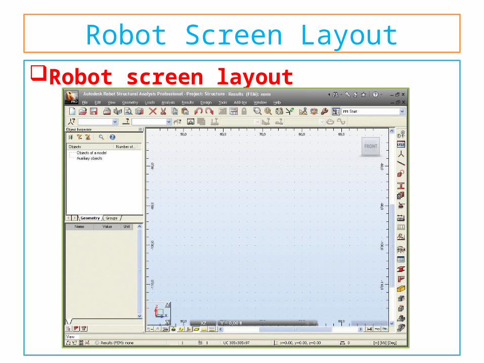
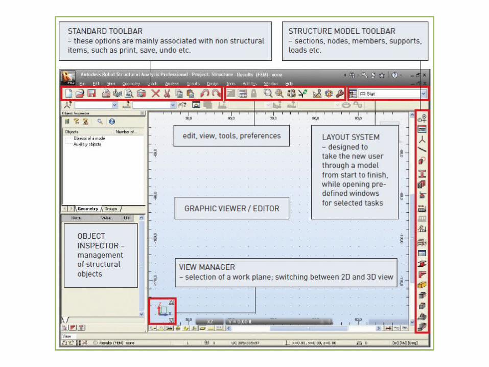
Robot Screen LayoutRobot screen layout
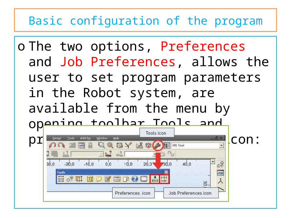
Basic configuration of the programo The two options, Preferences and Job
Preferences, allows the user to set program parameters in the Robot system, are available from the menu by opening toolbar Tools and pressing the appropriate icon:
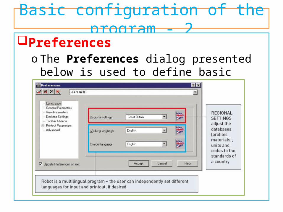
Basic configuration of the program - 2Preferences
o The Preferences dialog presented below is used to define basic parameters in the program:
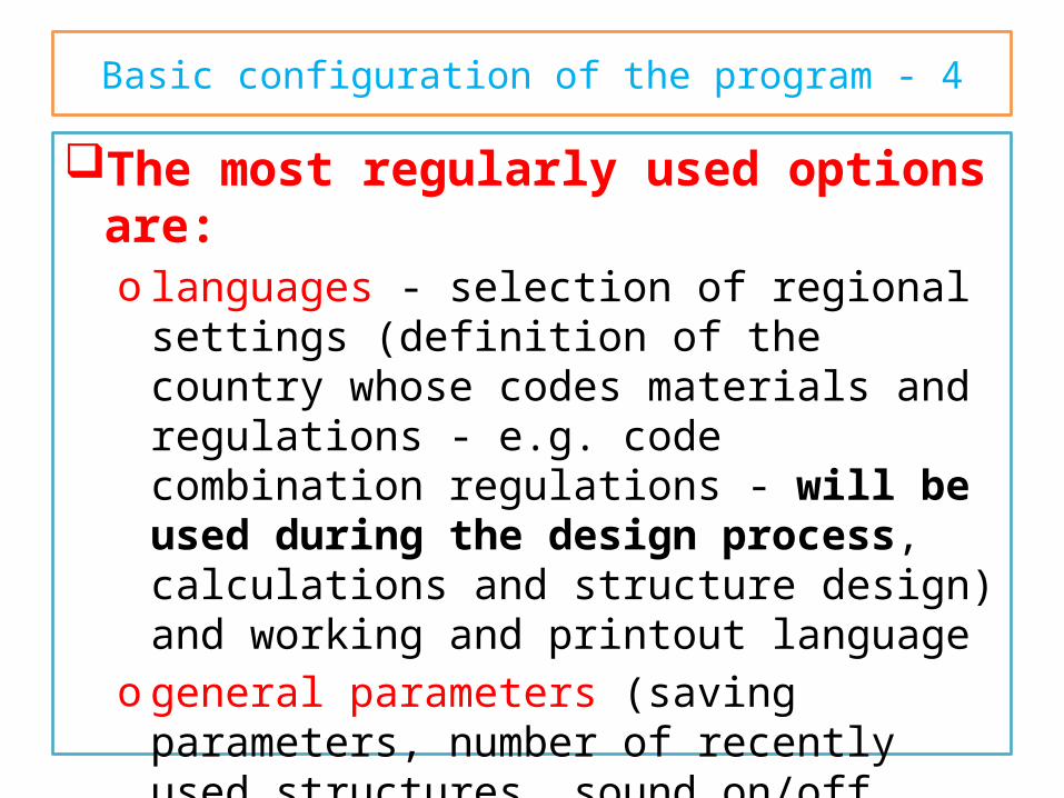
Basic configuration of the program - 4The most regularly used options are:
o languages - selection of regional settings (definition of the country whose codes materials and regulations - e.g. code combination regulations - will be used during the design process, calculations and structure design) and working and printout language
o general parameters (saving parameters, number of recently used structures, sound on/off etc.)
o display parameters (colors and fonts for screen components)
Basic configuration of the program - 5o toolbar and menu (menu type and the type of
toolbars)o printout parameters (colors and fonts for
printouts, scale and symbols, line thickness)o protection parameters (protection, authorization)
- for changing the system protectiono COM interface - presentation of the registered
additional programs/modules
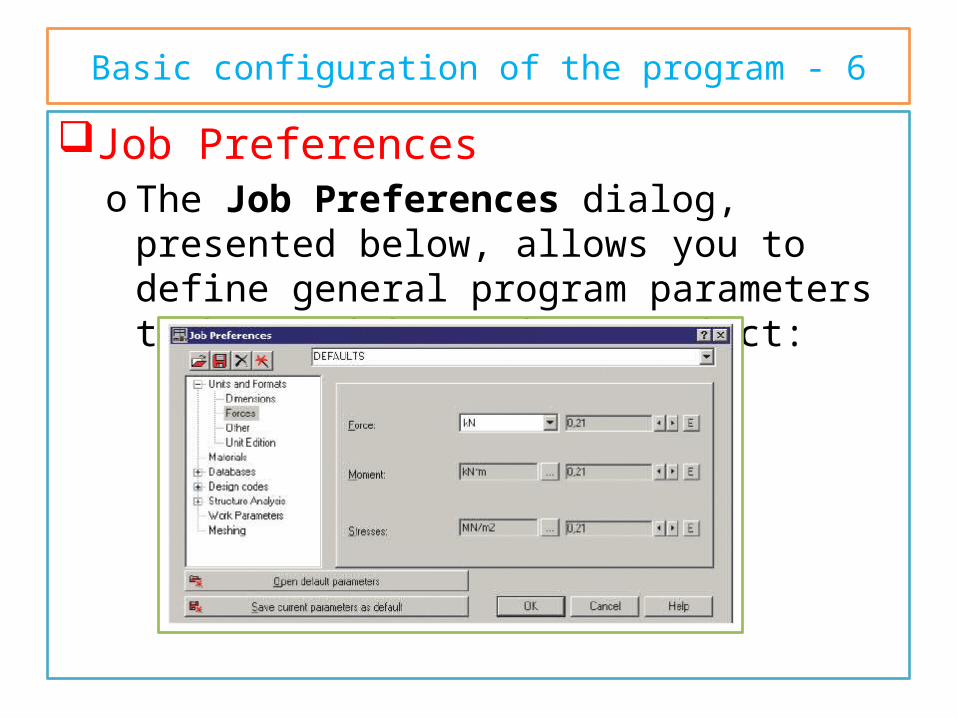
Basic configuration of the program - 6Job Preferences
o The Job Preferences dialog, presented below, allows you to define general program parameters to be used in a given project:
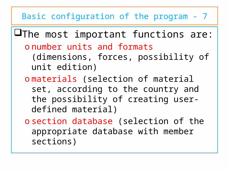
Basic configuration of the program - 7The most important functions are:
o number units and formats (dimensions, forces, possibility of unit edition)
omaterials (selection of material set, according to the country and the possibility of creating user-defined material)
o section database (selection of the appropriate database with member sections)
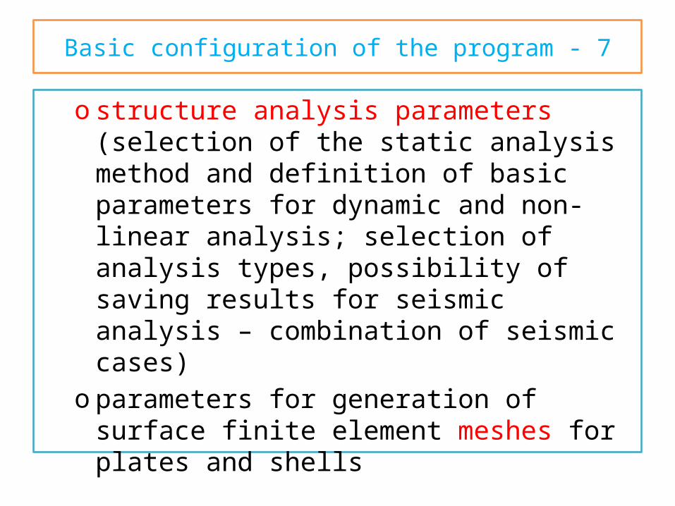
Basic configuration of the program - 7o structure analysis parameters (selection of the
static analysis method and definition of basic parameters for dynamic and non-linear analysis; selection of analysis types, possibility of saving results for seismic analysis – combination of seismic cases)
o parameters for generation of surface finite element meshes for plates and shells
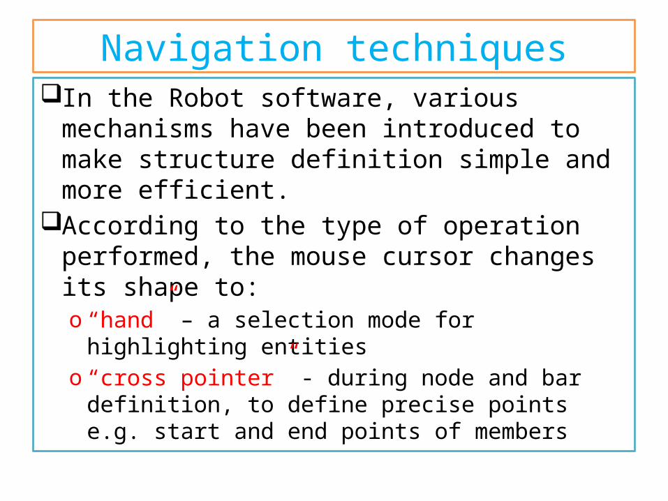
Navigation techniquesIn the Robot software, various mechanisms
have been introduced to make structure definition simple and more efficient.
According to the type of operation performed, the mouse cursor changes its shape to:o “hand” – a selection mode for highlighting entitieso “cross pointer” - during node and bar definition,
to define precise points e.g. start and end points of members
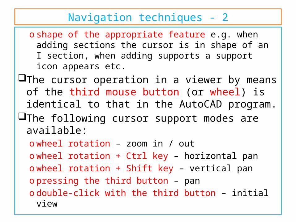
Navigation techniques - 2o shape of the appropriate feature e.g. when adding
sections the cursor is in shape of an I section, when adding supports a support icon appears etc.
The cursor operation in a viewer by means of the third mouse button (or wheel) is identical to that in the AutoCAD program.
The following cursor support modes are available:o wheel rotation – zoom in / outo wheel rotation + Ctrl key – horizontal pano wheel rotation + Shift key – vertical pano pressing the third button – pano double-click with the third button – initial view
Navigation techniques - 33D views Capabilities
oWhen Dynamic View (View → Dynamic View → Dynamic View) is switched on. 3D viewing enables work in one of five modes:
o four simple modes: 3D rotation, 2D rotation, zoom and pan
o one multi-function modeo After choosing a work mode, the mouse cursor
movement (with mouse left button pressed) brings about the relevant change in the 3D view:
Navigation techniques - 4o 3D Rotation – rotates a structure in all planeso 2D Rotation - rotates a structure in the plane
parallel to the screen planeo Zoom – movement down the view – zooming in /
zooming out a structure to / from the screen planeo Pan – movement in the view plane (structure shift
with respect to the screen center)
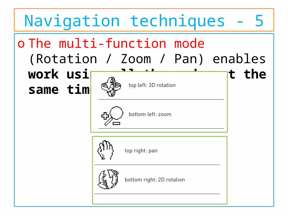
Navigation techniques - 5o The multi-function mode (Rotation / Zoom /
Pan) enables work using all the modes at the same time.
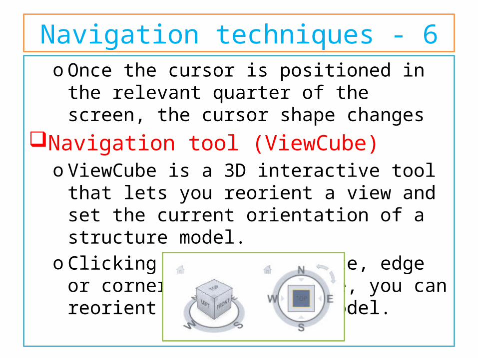
Navigation techniques - 6o Once the cursor is positioned in the relevant
quarter of the screen, the cursor shape changesNavigation tool (ViewCube)
o ViewCube is a 3D interactive tool that lets you reorient a view and set the current orientation of a structure model.
o Clicking a predefined face, edge or corner on the ViewCube, you can reorient the view of a model.
Navigation techniques - 7o clicking and dragging the ViewCube lets you
reorient the model to different directions.o Access the ViewCube option by selecting the View
> ViewCube - Properties.o The ViewCube also uses the compass to indicate a
direction from which you view a model.o To change the viewpoint of a model, click a
selected direction on the compass (N, S, E, W).o You can show or hide the compass from the
ViewCube context menu after you right-click on the ViewCube and select the Show compass option.
Method of Working with Robot Interface
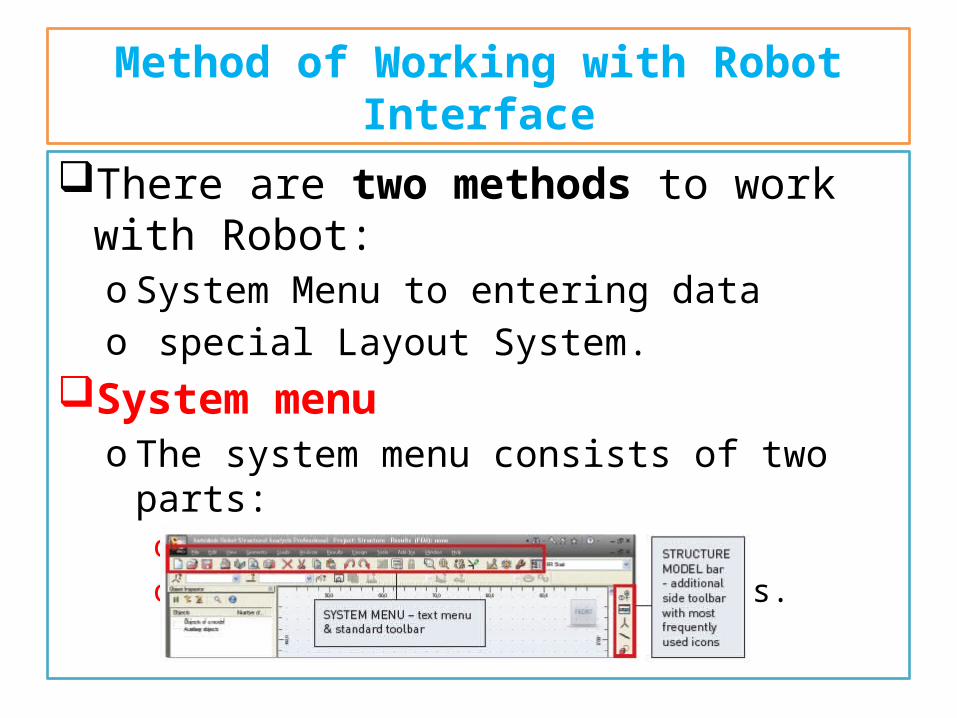
There are two methods to work with Robot:o System Menu to entering datao special Layout System.
System menuo The system menu consists of two parts:
o text menu o toolbars with appropriate icons.
Method of Working with Robot Interface - 2
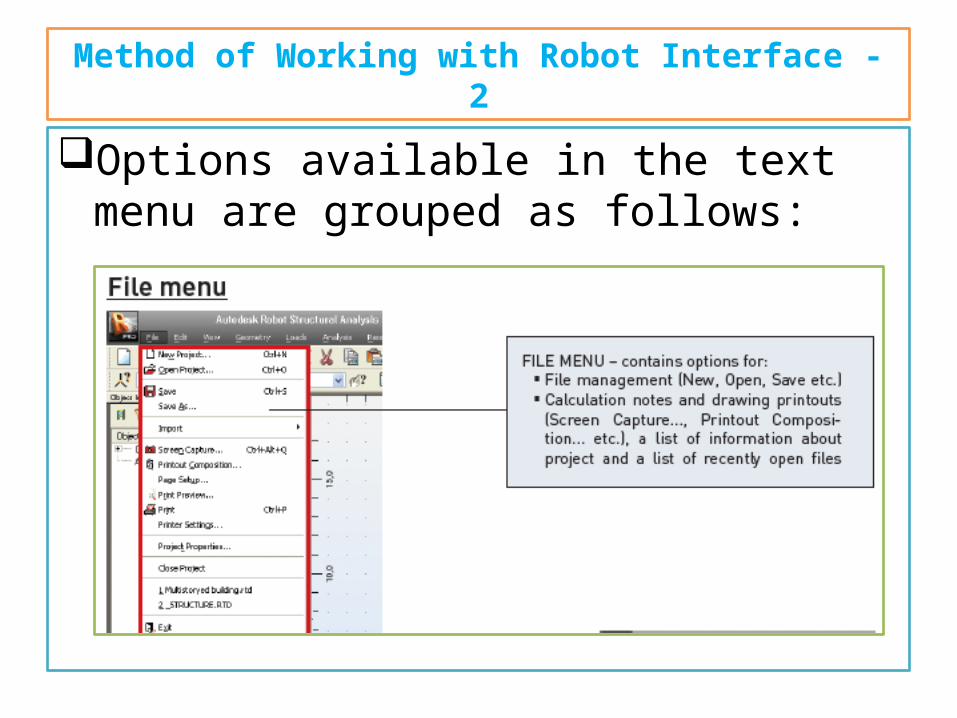
Options available in the text menu are grouped as follows:
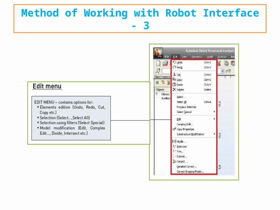
Method of Working with Robot Interface - 3
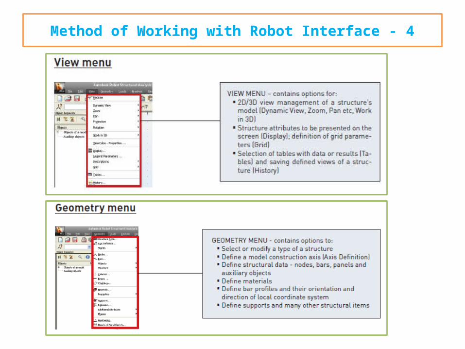
Method of Working with Robot Interface - 4
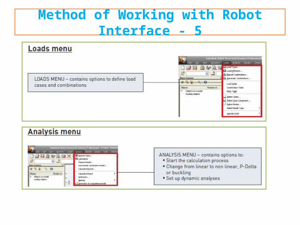
Method of Working with Robot Interface - 5
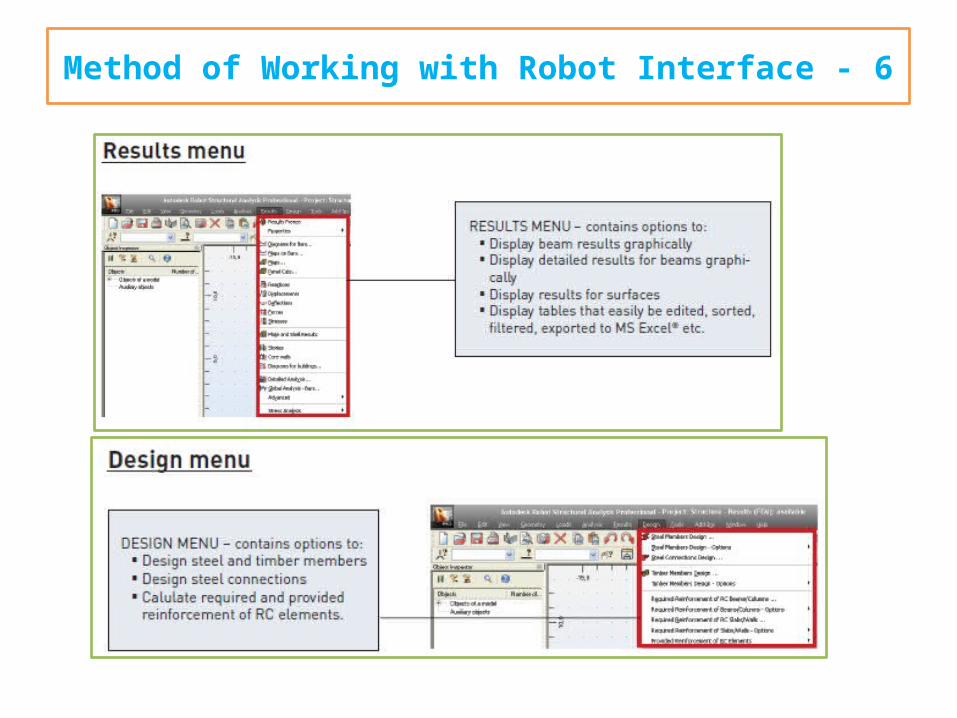
Method of Working with Robot Interface - 6
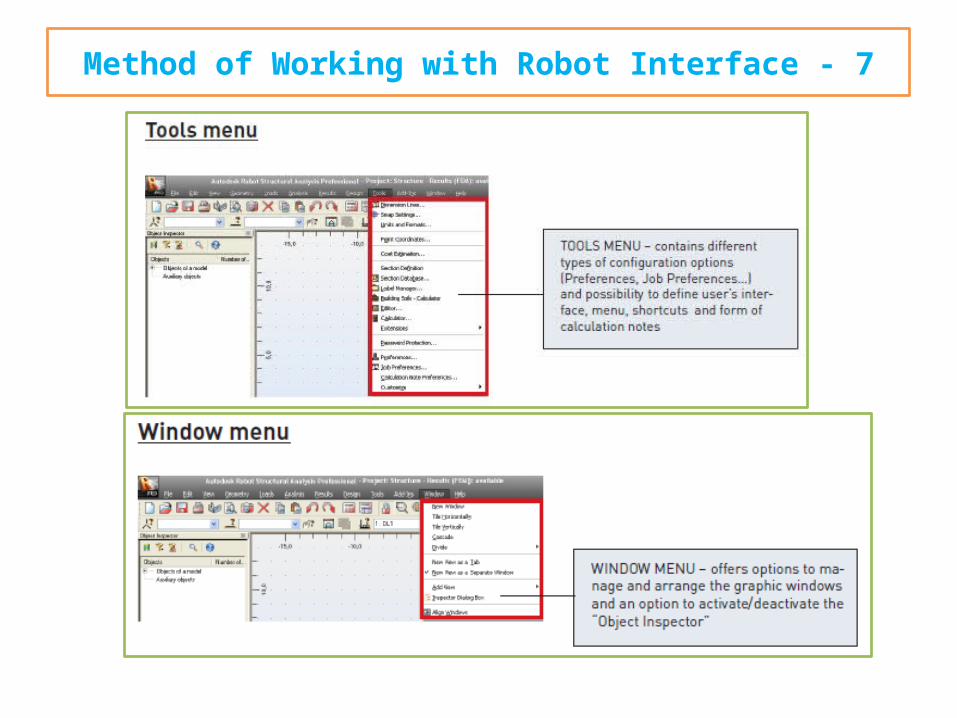
Method of Working with Robot Interface - 7
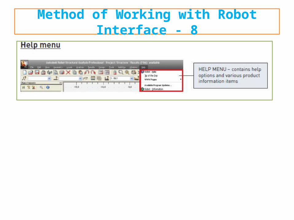
Method of Working with Robot Interface - 8
Method of Working with Robot Interface - 9
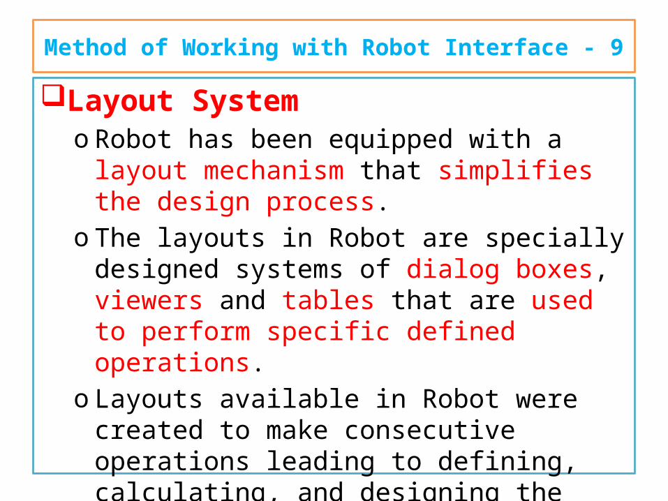
Layout Systemo Robot has been equipped with a layout
mechanism that simplifies the design process.o The layouts in Robot are specially designed
systems of dialog boxes, viewers and tables that are used to perform specific defined operations.
o Layouts available in Robot were created to make consecutive operations leading to defining, calculating, and designing the structure easier.
o the layouts guide the user through the process from model generation to results.
Method of Working with Robot Interface - 10
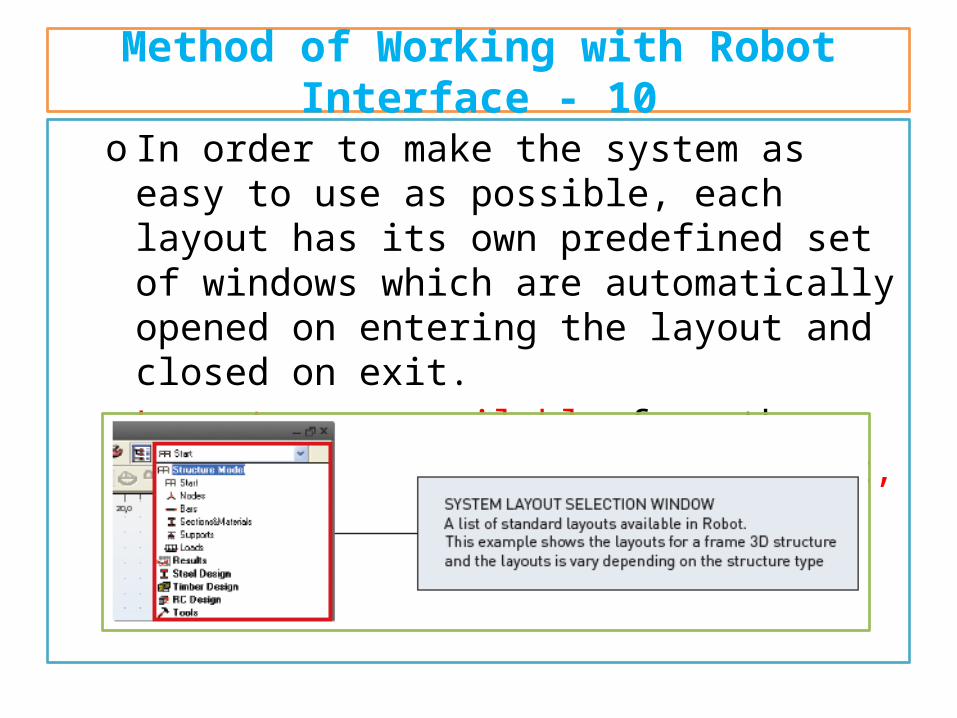
o In order to make the system as easy to use as possible, each layout has its own predefined set of windows which are automatically opened on entering the layout and closed on exit.
o Layouts are available from the selection list found in the right, upper corner of the screen:
Method of Working with Robot Interface - 11
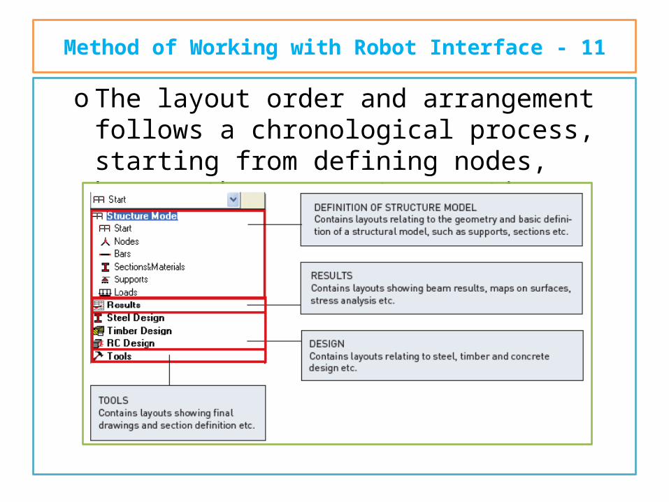
o The layout order and arrangement follows a chronological process, starting from defining nodes, beams, then supports, sections etc.
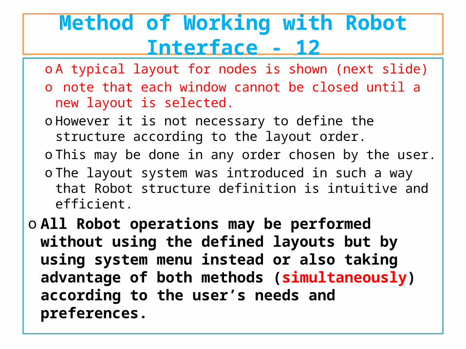
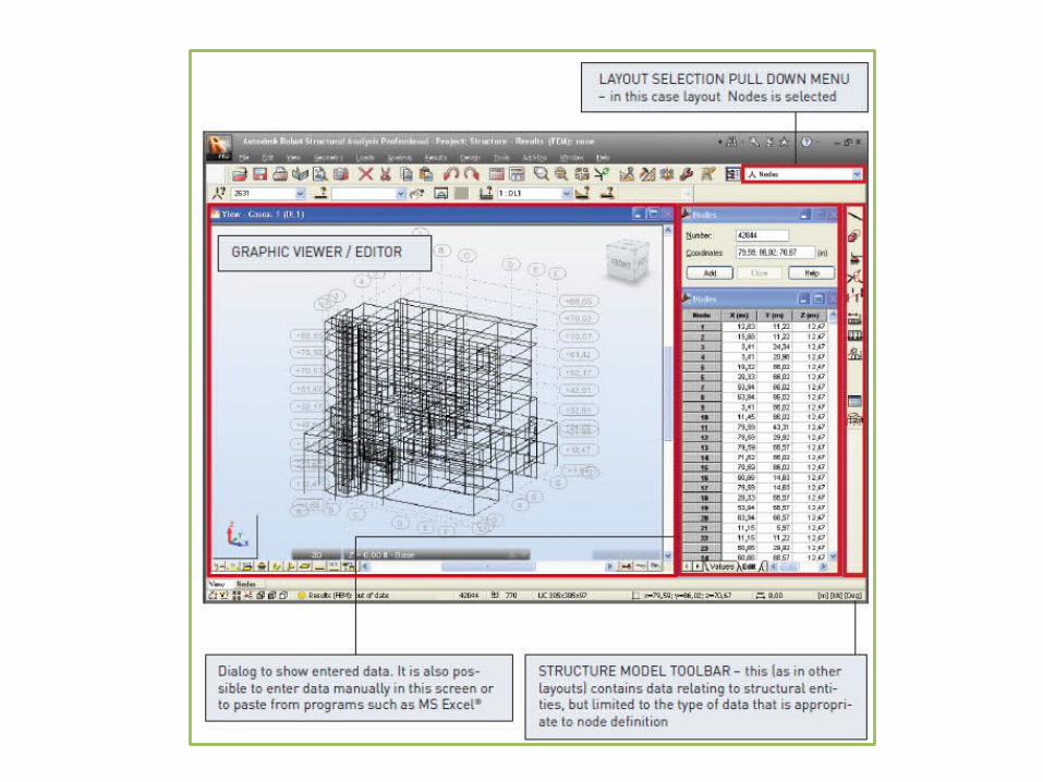
Method of Working with Robot Interface - 12
o A typical layout for nodes is shown (next slide)o note that each window cannot be closed until a new
layout is selected.o However it is not necessary to define the structure
according to the layout order.o This may be done in any order chosen by the user.o The layout system was introduced in such a way that Robot
structure definition is intuitive and efficient.o All Robot operations may be performed without
using the defined layouts but by using system menu instead or also taking advantage of both methods (simultaneously) according to the user’s needs and preferences.
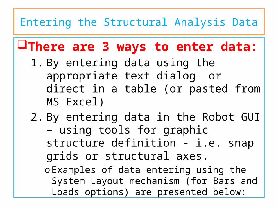
Entering the Structural Analysis DataThere are 3 ways to enter data:
1. By entering data using the appropriate text dialog or direct in a table (or pasted from MS Excel)
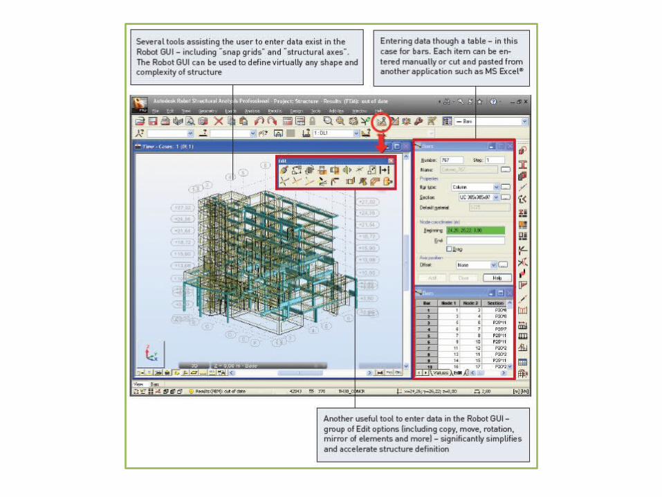
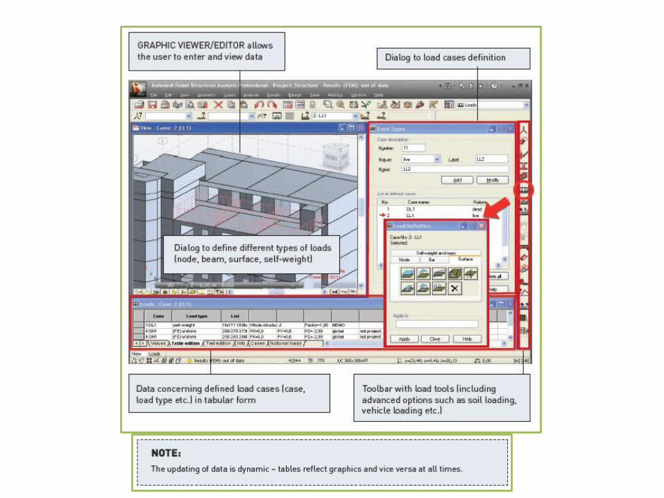
2. By entering data in the Robot GUI – using tools for graphic structure definition - i.e. snap grids or structural axes.o Examples of data entering using the System Layout
mechanism (for Bars and Loads options) are presented below:
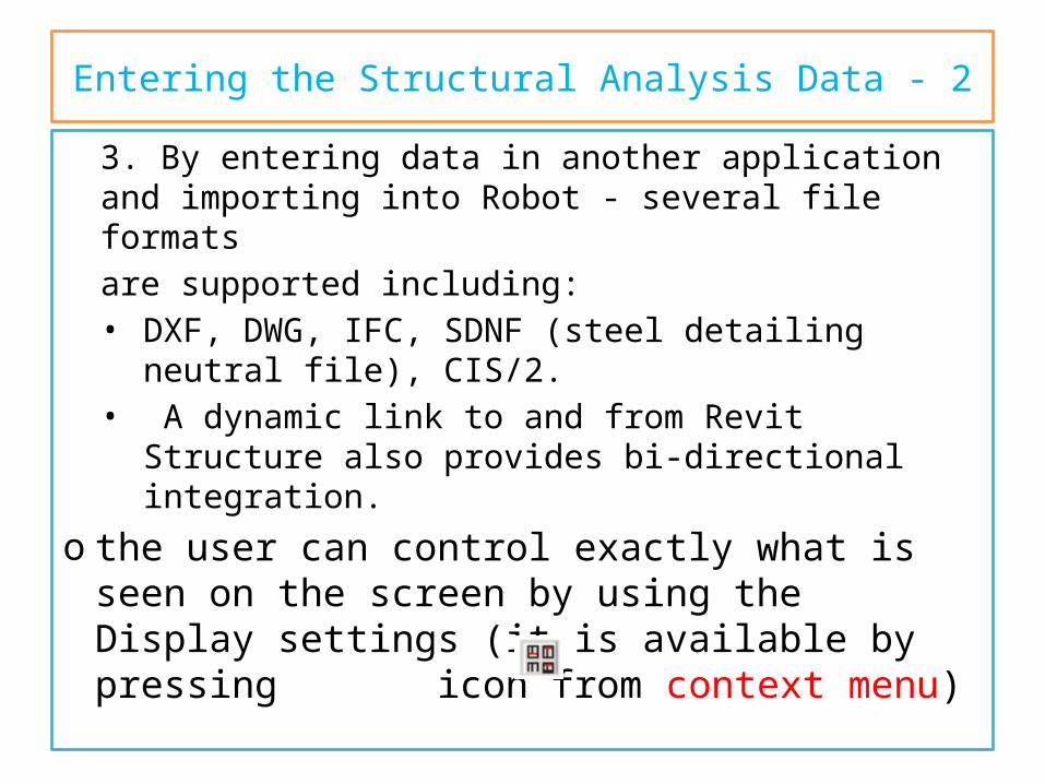
Entering the Structural Analysis Data - 23. By entering data in another application and importing into Robot - several file formatsare supported including:• DXF, DWG, IFC, SDNF (steel detailing neutral file),
CIS/2.• A dynamic link to and from Revit Structure also
provides bi-directional integration.o the user can control exactly what is seen on
the screen by using the Display settings (it is available by pressing icon from context menu)
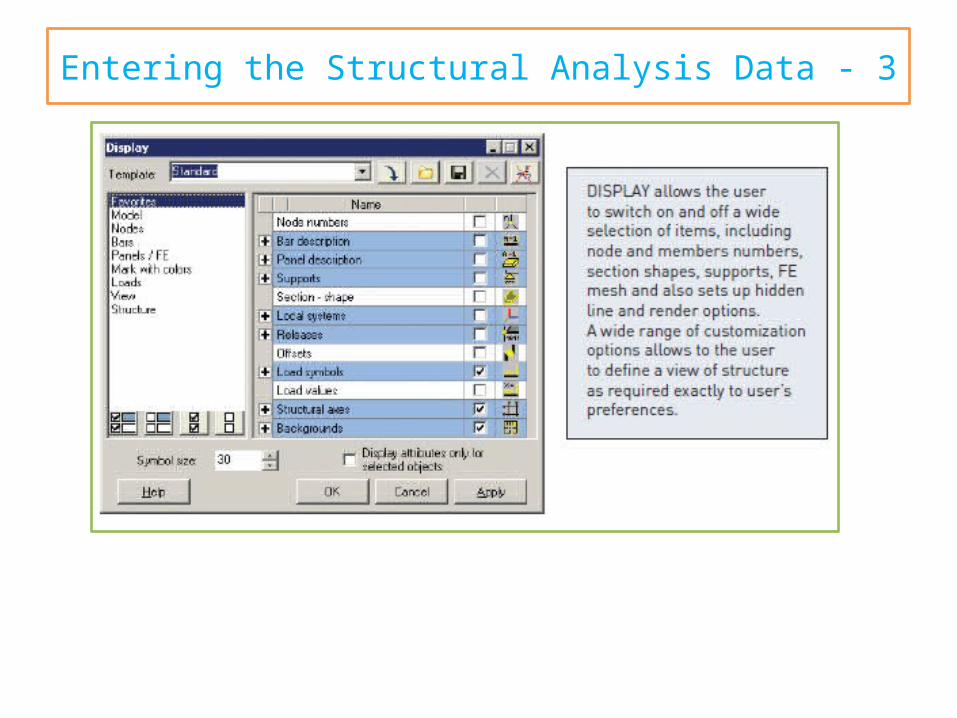
Entering the Structural Analysis Data - 3
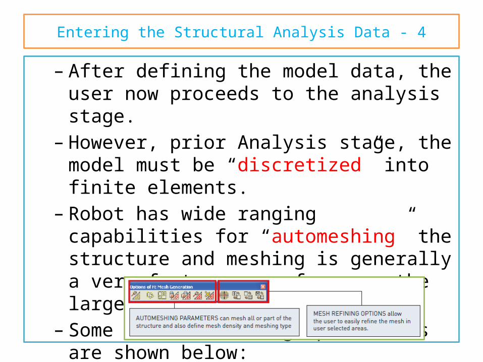
Entering the Structural Analysis Data - 4– After defining the model data, the user now
proceeds to the analysis stage.– However, prior Analysis stage, the model must be
“discretized” into finite elements.– Robot has wide ranging capabilities for
“automeshing” the structure and meshing is generally a very fast process for even the largest of models.
– Some of the “meshing” parameters are shown below:
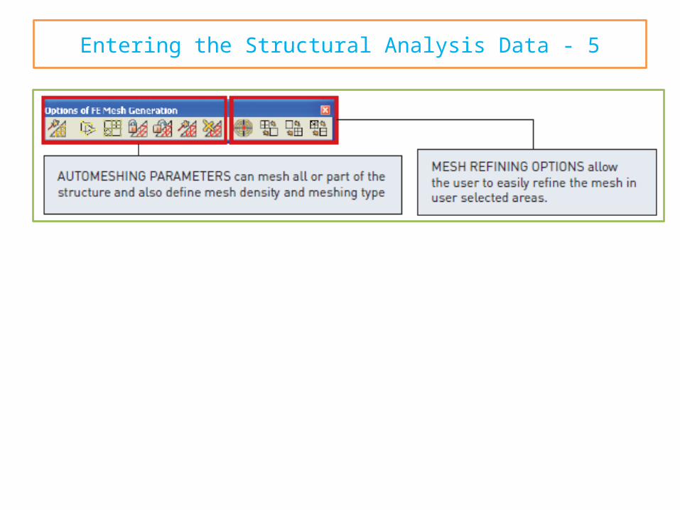
Entering the Structural Analysis Data - 5
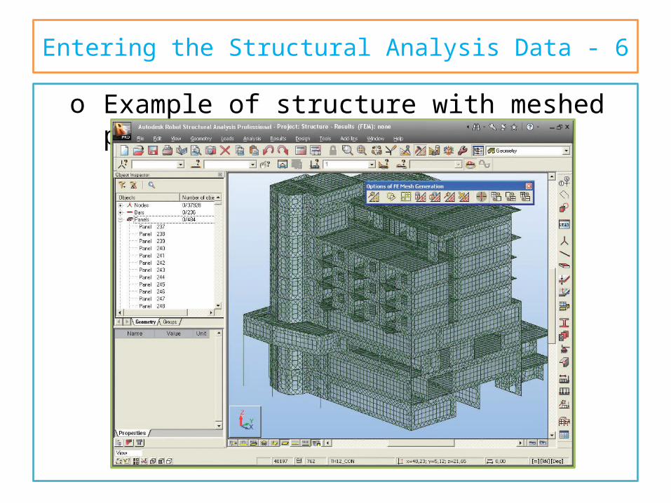
Entering the Structural Analysis Data - 6o Example of structure with meshed panels
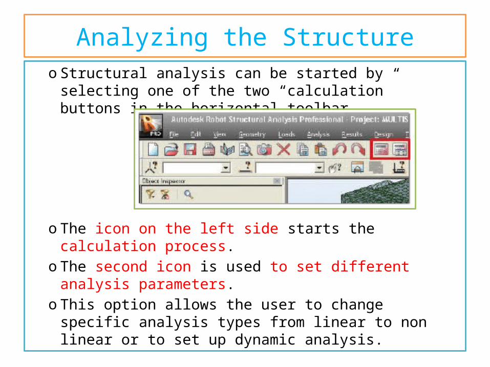
Analyzing the Structureo Structural analysis can be started by selecting one of
the two “calculation” buttons in the horizontal toolbar.
o The icon on the left side starts the calculation process.o The second icon is used to set different analysis
parameters. o This option allows the user to change specific analysis
types from linear to non linear or to set up dynamic analysis.
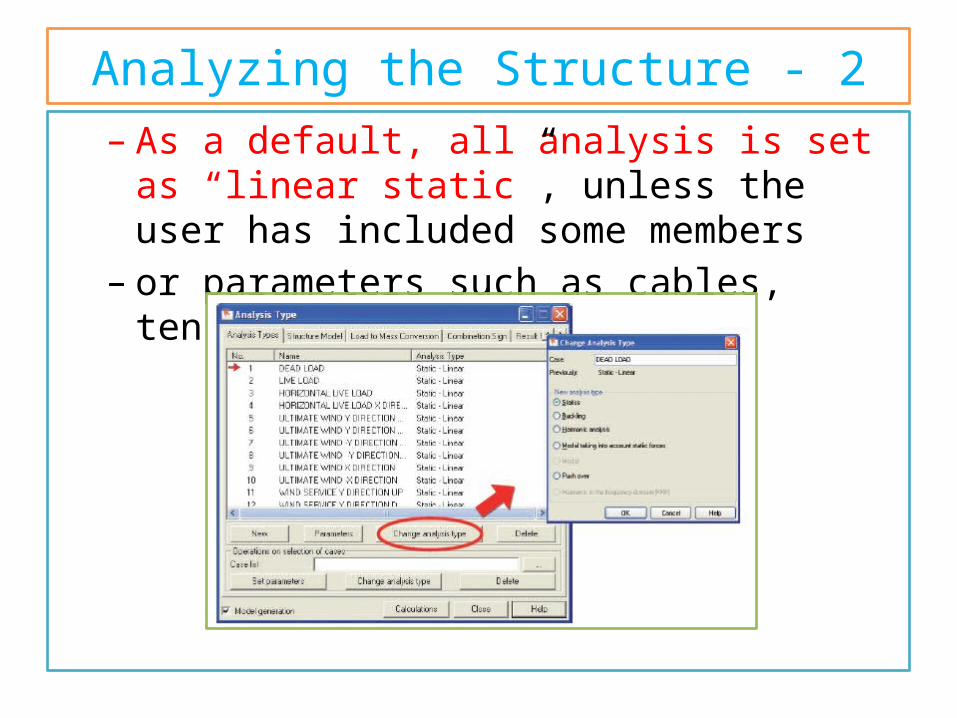
Analyzing the Structure - 2– As a default, all analysis is set as “linear static”,
unless the user has included some members– or parameters such as cables, tension only, hinges
etc.
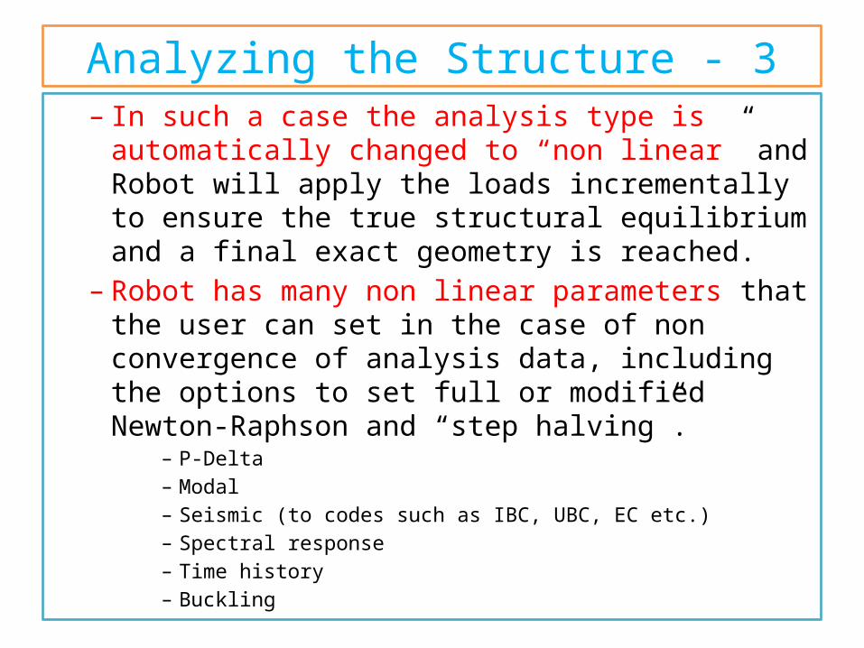
Analyzing the Structure - 3– In such a case the analysis type is automatically
changed to “non linear” and Robot will apply the loads incrementally to ensure the true structural equilibrium and a final exact geometry is reached.
– Robot has many non linear parameters that the user can set in the case of non convergence of analysis data, including the options to set full or modified Newton-Raphson and “step halving”.
– P-Delta– Modal– Seismic (to codes such as IBC, UBC, EC etc.)– Spectral response– Time history– Buckling
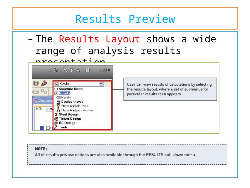
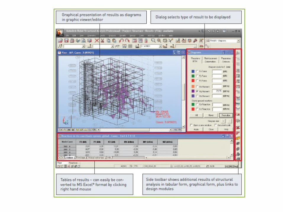
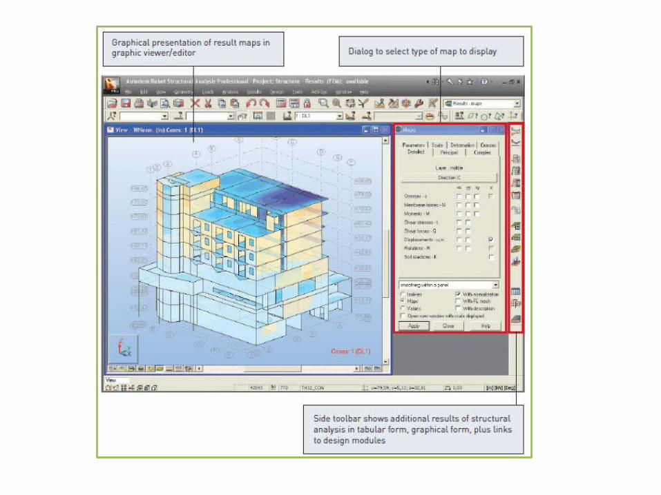
Results Preview
– The Results Layout shows a wide range of analysis results presentation.
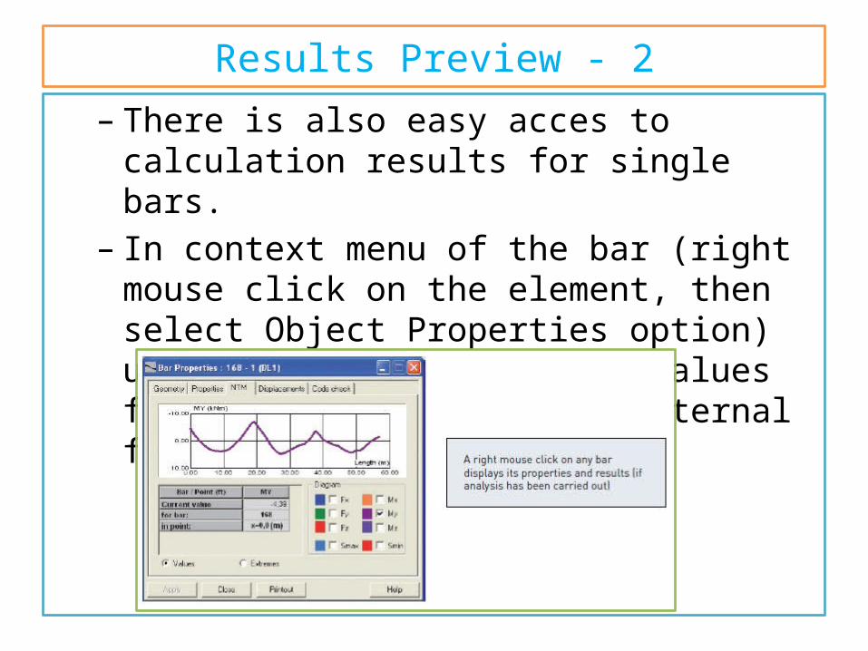
Results Preview - 2– There is also easy acces to calculation results for
single bars.– In context menu of the bar (right mouse click on
the element, then select Object Properties option) user can see diagrams and values for selected quantity of internal forces.
Results Preview - 3
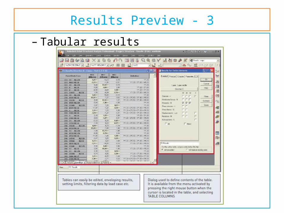
– Tabular results
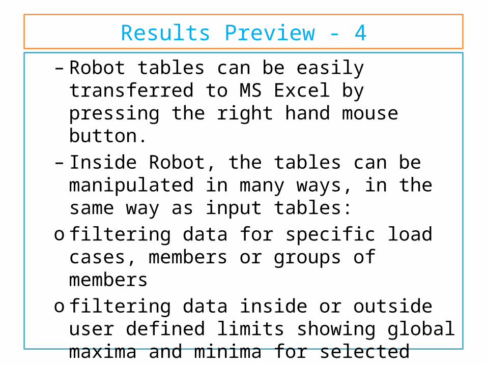
Results Preview - 4– Robot tables can be easily transferred to MS Excel
by pressing the right hand mouse button.– Inside Robot, the tables can be manipulated in
many ways, in the same way as input tables:o filtering data for specific load cases, members or
groups of memberso filtering data inside or outside user defined limits
showing global maxima and minima for selected members, nodes or surfaces
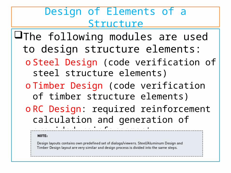
Design of Elements of a Structure
The following modules are used to design structure elements:o Steel Design (code verification of steel structure
elements)o Timber Design (code verification of timber
structure elements)o RC Design: required reinforcement calculation and
generation of provided reinforcement.
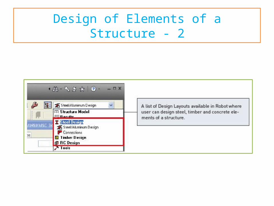
Design of Elements of a Structure - 2
Design of Elements of a Structure - 3
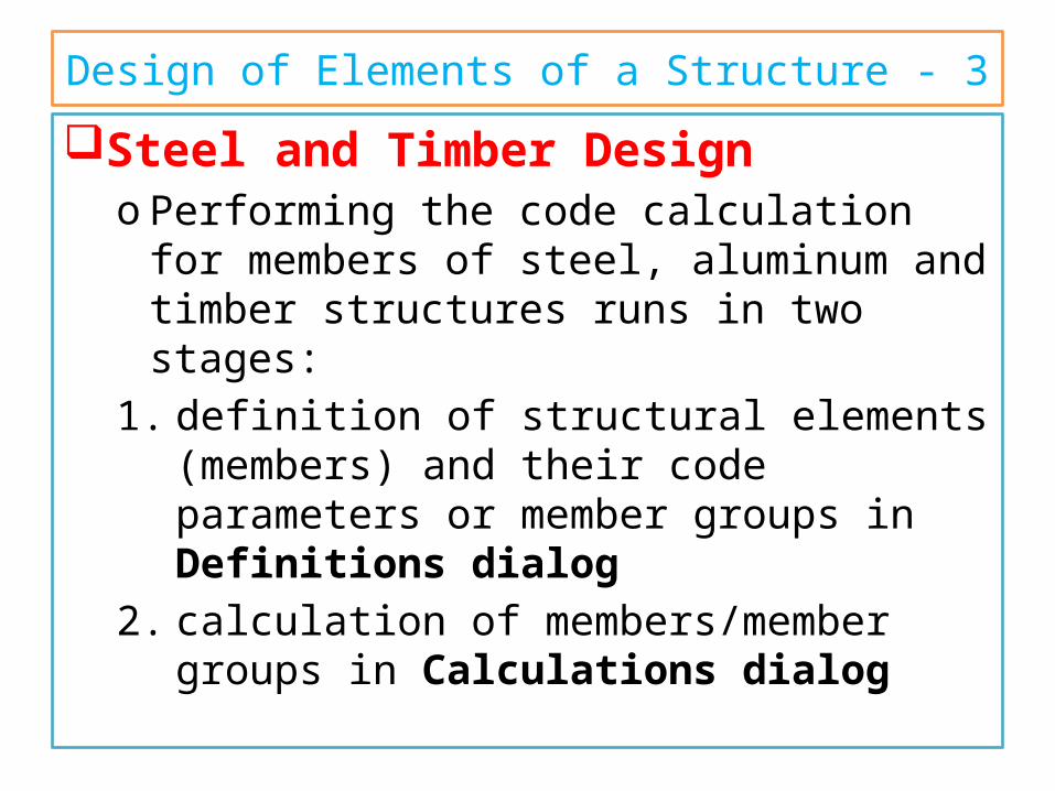
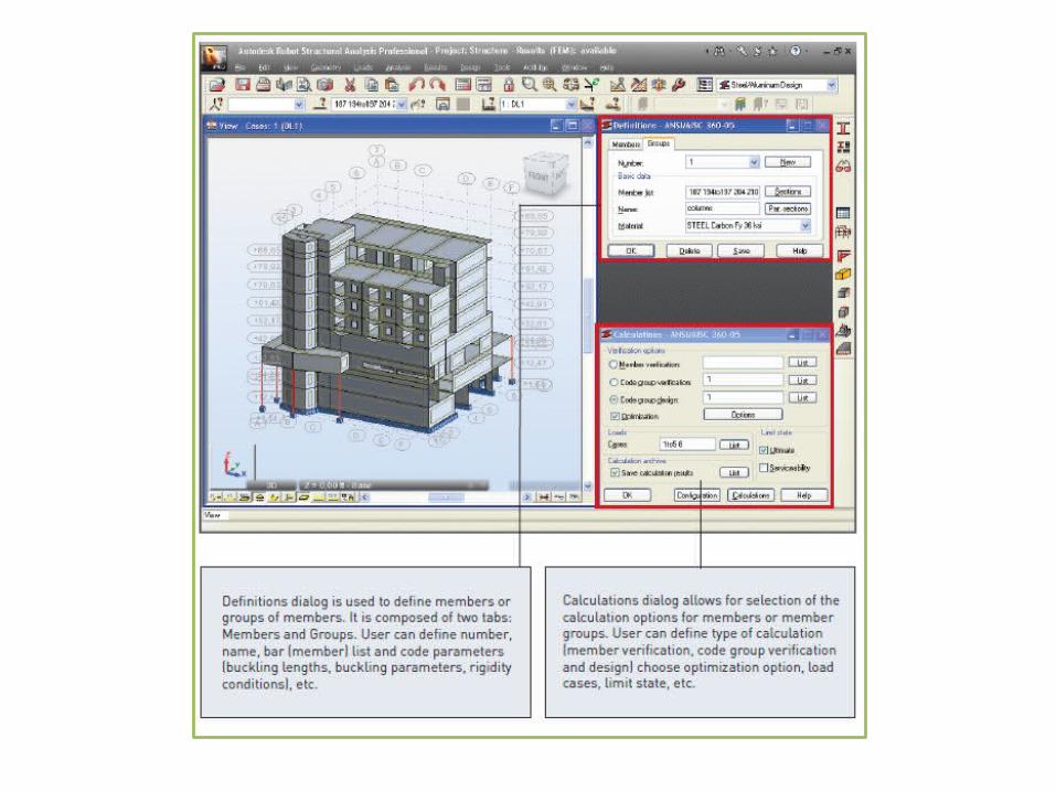
Steel and Timber Designo Performing the code calculation for members of
steel, aluminum and timber structures runs in two stages:
1. definition of structural elements (members) and their code parameters or member groups in Definitions dialog
2. calculation of members/member groups in Calculations dialog
Design of Elements of a Structure - 4
– After setting parameters in the Definitions and Calculations dialogs user can start member verification/design by pressing the Calculations button (lower part of the Calculations dialog).
– Once the calculations are completed, the Results dialog will be displayed.
Calculations results can be presented as:o Short results.o Simplified and detailed results
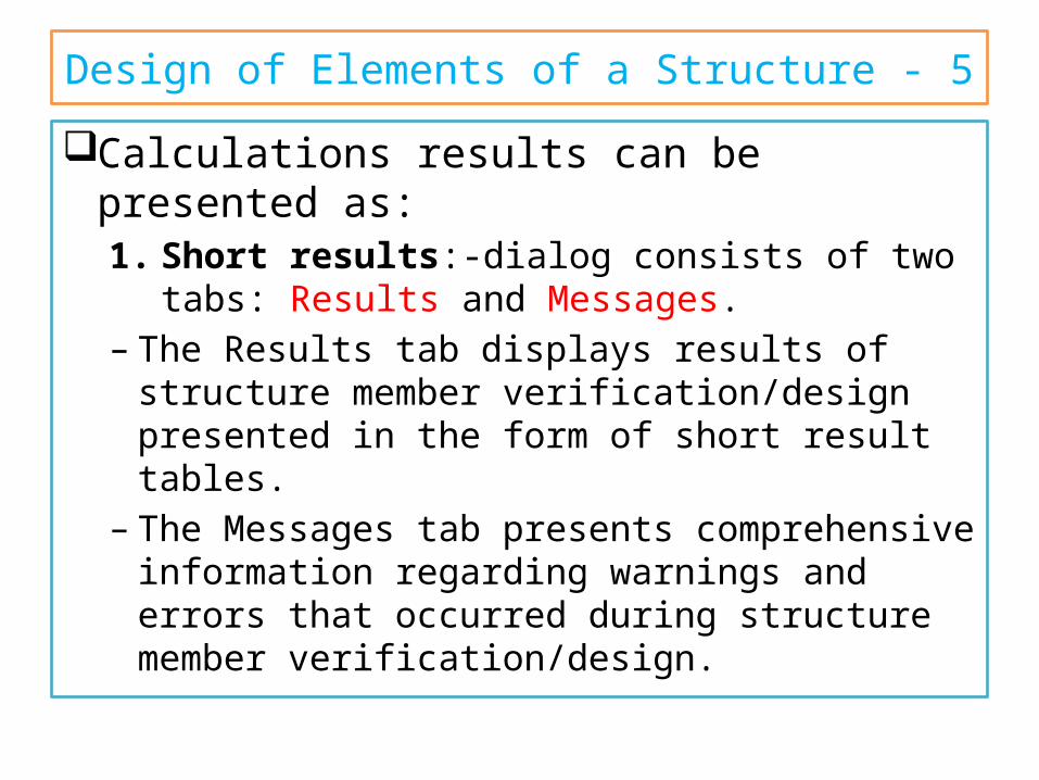
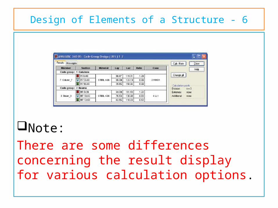
Design of Elements of a Structure - 5
Calculations results can be presented as:1. Short results:-dialog consists of two tabs: Results
and Messages. – The Results tab displays results of structure
member verification/design presented in the form of short result tables.
– The Messages tab presents comprehensive information regarding warnings and errors that occurred during structure member verification/design.
Design of Elements of a Structure - 6
Note:There are some differences concerning the result display for various calculation options.
Design of Elements of a Structure - 7
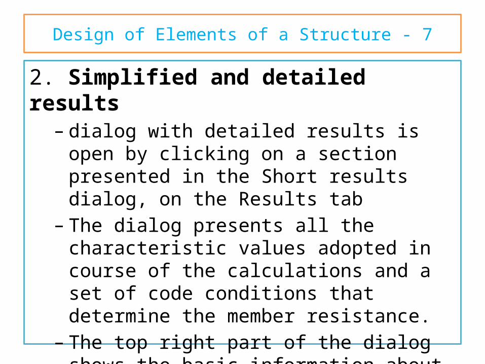
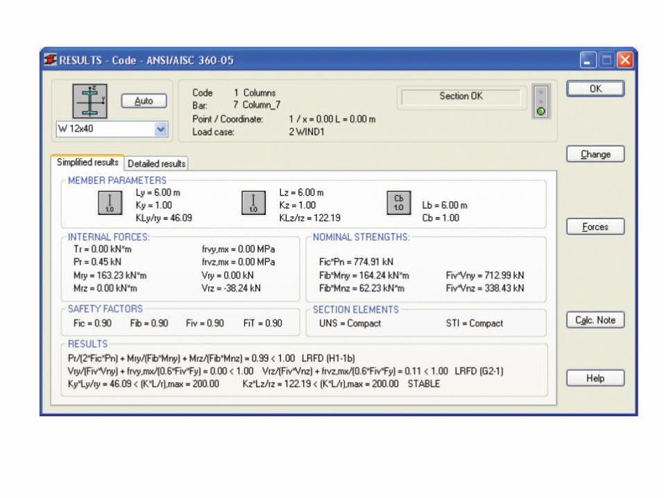
2. Simplified and detailed results– dialog with detailed results is open by clicking on a
section presented in the Short results dialog, on the Results tab
– The dialog presents all the characteristic values adopted in course of the calculations and a set of code conditions that determine the member resistance.
– The top right part of the dialog shows the basic information about a section: SECTION OK
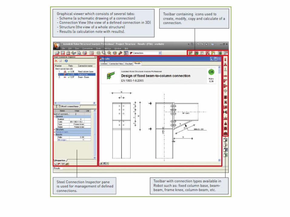
Steel Connections DesignTo start the code verification of steel connections,
select the Steel Design / Connections layout (available in the Steel Design layout group).
NOTE:The following codes are available, allowing you to calculate steel structure connections:
o Eurocode (ENV 1993-1-1:1992 and EN 1993-1-8:2005)o French steel code CM66 and Polish steel code PN-90/B-
03200o The national versions of the Eurocode 3 code for steel
connections: o French (NF-EN1993-1-8:2007) ando Polish (PN-EN 1993-1-8:2006) are available.
Steel Connections Design - 2The code calculations of steel connections run
in two stages:1. definition of geometry of a connection (a
connection type) and its parameters.o It is possible to create connection within the
structure (by selected bars in the structure) or connection defined manually (a stand-alone connection).
2. calculation of the defined connection for selected parameters and load cases.
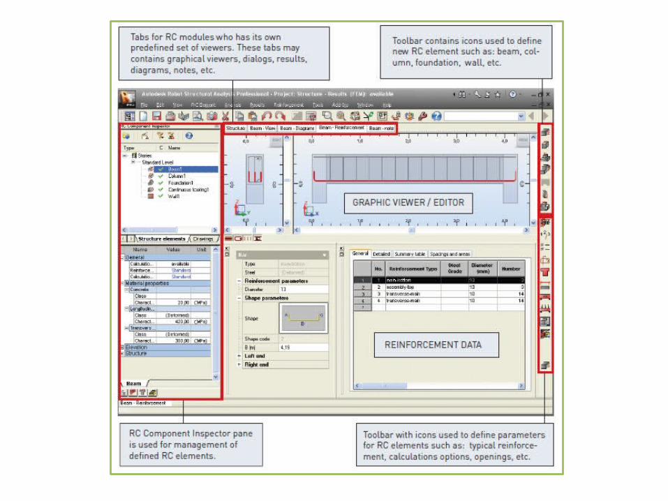
RC DesignThe Robot offers two possibilities for a design
of RC structure members:o calculation of the required reinforcement area
needed for the RC membero generation of the provided reinforcement for the
RC member
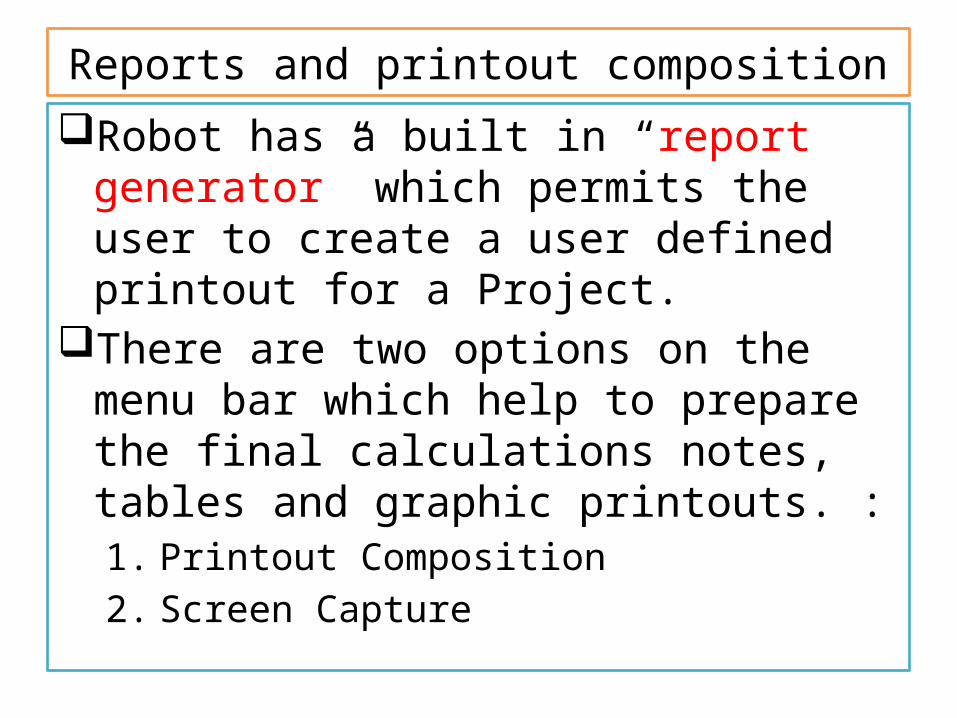
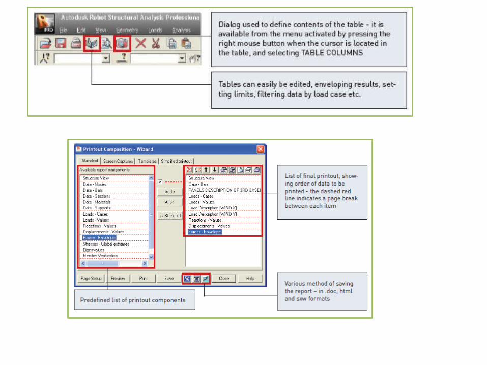
Reports and printout compositionRobot has a built in “report generator” which
permits the user to create a user defined printout for a Project.
There are two options on the menu bar which help to prepare the final calculations notes, tables and graphic printouts. :1. Printout Composition2. Screen Capture
3D FRAME STRUCTURE