Embed Size (px)
Citation preview

TRITON COLLEGE
AUTODESK REVIT ARCHITECTURE 2008
ARC 262 – BIM PRODUCTION
Instructor: Mel Persin, AIA Date: January 26, 2008

Learning Autodesk® Revit
® Architecture 2008
Chapter Exercises Preface: Introduction to Revit Architecture 2008
Setting Up and Using the Exercises Introduction to Building Information Modeling Fundamental Concepts Revit Architecture 2008 Understanding Revit Architecture 2008 Terms
Chapter 1: The Revit Architecture 2008 Interface
Chapter 2: Building Information Modeling
Chapter 3: Using Revit Architecture 2008
Chapter 4: Starting a Design
Chapter 5: Creating a Building
Chapter 6: Using Dimensions and Constraints
Chapter 7: Developing the Building Model
Chapter 8: Using Building Components
Chapter 9: Creating Schedules
Chapter 10: Drafting and Detailing
Chapter 11: Presenting the Building Model
Chapter 12: Developing the Site
Additional: Working in Teams

ii/ix

iii/ix
ARC 262: Introduction to Revit Architecture 2008 Course Overview:
Welcome to Triton College ARC 262 Autodesk Revit Architecture 2008. This workbook contains exercises designed to teach the principles of Building Information Modeling (BIM), the process of developing Parametric Building Models (PBM), and the features and tools required to develop the architectural model and construction documents using Autodesk Revit Architecture 2008 software.
Course Objectives: The Objectives of this course are:
• To provide the student with a working knowledge of BIM technology and Autodesk Revit Architecture 2008 software.
• To provide the student with the fundamental skills to develop, manage and coordinate Revit Architecture 2008 projects: setting up, importing, exporting and linking files, project collaboration and management, and presentation methods.
• To provide the student with fundamental skills necessary to use Revit Architecture 2008 to create 3D building models; and 2D plan, elevation, section, detailed, drafting and schedule views.
Exercise Objectives: The objective of these exercises are:
• To provide the student with easy-to-use, hands-on exercises to learn the features, tools, commands and functionality of Autodesk Revit Architecture 2008 in creating building models and developing construction documents.
• To provide the student an understanding in using 3D building modeling to construct a parametric building model, working with building components and managing building component constraints and relationships, in the process of developing a project schematic design through construction documents, illustrating the practice currently used and extending the process to leverage building information modeling.
• To provide the student with an understanding of managing, collaborating and coordinating CAD 2D drafting to 3D building modeling and the transition the architectural design and document process that is occurring throughout the design profession as building information modeling reshapes both traditional presentation and documentation practices, and client related services in order to provide a better process and method for building projects.
Prerequisites: It is required that those attending this course have a working knowledge of architectural drafting practices and building construction technology: A working knowledge of Microsoft Windows and CAD software.

Setting Up and Using the Exercises Using the Exercises:
The associated Autodesk Revit Architecture 2008 project, family, AutoCAD drawing and support files are to be installed in new folder named “Revit Architecture 2008 Basics” created on your desktop. The files for the exercises and the related support folders (Revit Firehouse and Training Library) are placed in a sub folder named “Courseware”. When working with the chapter exercises in this courseware, open the file specified by navigating to the Revit Architecture 2008\Courseware folder in your student account folder and open the specified .RVT file. Revit Imperial Template folder (RTE), Imperial Library folder Family content (RFA), Rendering folder resource materials and Training folder exercise files can be found under the “C:\Documents and Settings\All Users\Application Data\Autodesk\Revit Architecture 2008” folder.
Getting Started: Start Autodesk Revit Architecture 2008 from the icon on the Windows desktop and resize the application so you can still see this window.
iv/ix

Introduction to Building Information Modeling Overview: Building information modeling integrates information from all aspects of the building process and dramatically increases its utility and availability. It is a building design, delivery and management approach characterized by the continuous, immediate, high quality, and reliable integration of geometry, schedule, and Take-Off information in a fully relational digital model. As such, building information modeling is more than a repository of knowledge. It is a key decision making tool that exposes the resulting effects of any changes/scenarios across all three areas to enable better decision making and better quality and productivity in documentation. Building Information Modeling
(BIM) – The creation and use of coordinated, internally consistent, computable information about a building project in design and construction.
Building – The design project, as you envision it for the client
Information – The drawings, schedules, specifications, fully coordinated
Modeling – The digital description that can be explored and evaluated before you build
The Autodesk Revit parametric building model is composed of project views (drawings and schedules), annotations (dimensions, section and detail keys, etc.), and building components (parts of the building) bound together into a single, integrated whole by Revit’s parametric change engine. The result: a change anywhere is instantly reflected everywhere.
v/ix

vi/ix
Concepts Autodesk Revit Architecture 2008 Understanding the Basics In this lesson, you learn what Revit Architecture 2008 is and how its parametric change engine benefits you and your work. You begin with the fundamental concepts that Revit Architecture 2008 is built upon. You learn the terminology, the hierarchy of elements, how to navigate the user interface, and how to perform some common tasks in the product. What is Autodesk Revit Architecture? The Revit Architecture 2008 platform for building information modeling is a design and documentation system that supports the design, drawings, and schedules required for a building project. Building information modeling (BIM) delivers information about project design, scope, quantities, and phases when you need it. In the Revit Architecture 2008 model, every drawing sheet, 2D and 3D view, and schedule is a presentation of information from the same underlying building model database. As you work in drawing and schedule views, Revit Architecture 2008 collects information about the building project and coordinates this information across all other representations of the project. The Revit Architecture 2008 parametric change engine automatically coordinates changes made anywhere—in model views, drawing sheets, schedules, sections, and plans. What is meant by parametric? The term parametric refers to the relationships among all elements of the model that enable the coordination and change management that Revit Architecture 2008 provides. These relationships are created either automatically by the software or by you as you work. In mathematics and mechanical CAD, the numbers or characteristics that define these kinds of relationships are called parameters; hence, the operation of the software is parametric. This concept is important because it is this capability that delivers the fundamental coordination and productivity benefits of Revit Architecture 2008: Change anything at any time anywhere in the project, and Revit Architecture 2008 coordinates that change through the entire project. The following are examples of these element relationships:
The outside of a door frame is a fixed dimension on the hinge side from a perpendicular partition. If you move the partition, the door retains this relationship to the partition.
Windows or pilasters are spaced equally across a given elevation. If the length of the elevation is changed, the relationship of equal spacing is maintained. In this case, the parameter is not a number but a proportional characteristic.
The edge of a floor or roof is related to the exterior wall such that when the exterior wall is moved, the floor or roof remains connected. In this case, the parameter is one of association or connection.

How does Autodesk Revit Architecture keep things updated? A fundamental characteristic of a building information modeling application is the ability to coordinate changes and maintain consistency at all times. You do not have to intervene to update drawings or links. When you change something, Revit Architecture 2008 immediately determines what is affected by the change and reflects that change to any affected elements. Revit Architecture 2008 uses two key concepts that make it especially powerful and easy to use. The first is the capturing of relationships while the designer works. The second is its approach to propagating building changes. The result of these concepts is software that works like you do, without requiring entry of data that is unimportant to your design. Element behavior in a parametric modeler Revit Architecture 2008 uses five software element classes: host, component, annotation, view, and datum. Hosts include walls, floors, roofs, and ceilings. Components include windows, doors, and furniture. Annotations are 2D, view-specific elements that help you produce your
documentation. Views are dynamic representations of the model and are always up-to-date. Datums are reference elements that help you put your building together.
This implementation provides flexibility for designers. Revit Architecture 2008 elements are designed to be created and modified by you directly; programming is not required. If you can draw, you can define new parametric elements in Revit Architecture 2008.
vii/ix

viii/ix
Understanding Autodesk Revit Architecture 2008 Terms Most of the terms used to identify objects in Revit Architecture 2008 are common, industry-standard terms familiar to most architects. However, there are some terms that are unique to Revit Architecture 2008, and understanding them is crucial to understanding the software. This section defines the basic terms used in Revit Architecture 2008.
Project: In Revit Architecture 2008, the project is the single database of information for your design—the building information model. The project file contains all the information for your building design, from geometry to construction data. This information includes components used to design the model, views of the project, and drawings of the design. By using a single project file, Revit Architecture 2008 makes it easy for you to alter your design and have changes reflected in all associated areas (plan views, elevation views, section views, schedules, and so forth). Having only one file to track also makes it easier to manage the project. Level: Levels are infinite horizontal planes that act as a reference for level-hosted elements, such as roofs, floors, and ceilings. Most often, you use levels to define a vertical height or story within a building. You create a level for each known story or other needed reference of the building; for example, first floor, top of wall, or bottom of foundation. To place levels, you must be in a section or elevation view. Element: When creating your project, you add Revit Architecture 2008 parametric building elements to the design. All elements are considered categories. Revit Architecture 2008 classifies elements by model component elements and annotation elements. • A model component element, such as a door, desk, or roof, represents the
actual 3D geometry of the building. • An annotation building element, such as a door tag, elevation symbol, or
room tag, helps document the model. Family: Families are classes of elements in a category that group elements with a common set of parameters (properties), identical use, and similar graphical representation. Different elements in a family may have different values for some or all properties, but the set of properties—their names and meaning—is the same. For example, six-panel colonial doors could be considered one family, although the doors that compose the family come in different sizes and materials. Families are either component families or system families: • Component family files can be loaded into a project and created from
family templates. You can determine the set of properties and the graphical representation of the family.
• System families include walls, dimensions, ceilings, roofs, floors, and levels, and are not available for loading or creating as separate files.
• Revit Architecture 2008 predefines the set of properties and the graphical representation of system families.
• You can use the predefined types to generate new types that belong to this family within the project. For example, the behavior of a wall is

ix/ix
predefined in the system; however, you can create different types of walls with different compositions.
• System families can be transferred between projects. Type: Each family can have different types. A type can be a specific size of a family, such as a 30” X 42” title block or a 32" x 84" door. A type can also be a style, such as default aligned or default angular style for dimensions. A family can have several types. For example, a table could come in several different sizes. Each different size would be a new type within the same family. Instance: Instances are the actual items that are placed in the project and have specific locations in the building (model instances) or on a drawing sheet (annotation instances).

1/223

Chapter 1: The Autodesk Revit Architecture 2008 Window • Exercise: Starting a New Project and Working with Revit Template Files
• Exercise: Exploring the Revit Architecture 2008 Window
Navigating the User Interface One of the advantages of Revit Architecture 2008 is its ease of use, specifically its clear user interface. The Revit Architecture 2008 window is arranged to make navigation easy. Even the toolbar buttons are labeled, making it easy to understand what each button represents. Revit Architecture 2008 uses standard Microsoft® Windows® conventions. If you have used any other product that follows these conventions, learning Revit Architecture 2008 is much easier. In the following illustration, the user interface is labeled. In the steps that follow, you navigate and become familiar with the user interface.
2/213

Exercise: Starting Projects/Working with Template Files Start a new project 1. On the Standard toolbar, click .
This creates a new project based on the default template. 2. On the Menu bar select File > New, in the flyout menu select Project.
The New Project dialog box opens.
Pick the Browse button.
Observe the five Revit template files with the RTE extension, select Residential-Default.rte and pick the open button.
NOTE: In the Create New area of the New Project dialog box Project and Project template. You can open the template files and edit them to include project properties, settings, standards, family content, browser view, groups and sheets used for starting various project types.
3/213

3. Review the different project settings, project browser views, system family types for walls, element and component families loaded and sheets setup in the Residential-Default.rte versus the Default.rte template files
4/213
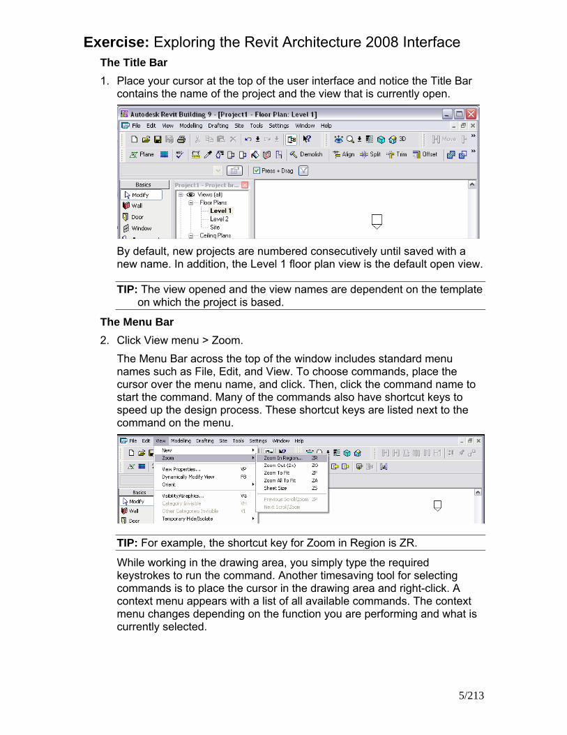
Exercise: Exploring the Revit Architecture 2008 Interface The Title Bar 1. Place your cursor at the top of the user interface and notice the Title Bar
contains the name of the project and the view that is currently open.
By default, new projects are numbered consecutively until saved with a new name. In addition, the Level 1 floor plan view is the default open view.
TIP: The view opened and the view names are dependent on the template on which the project is based.
The Menu Bar 2. Click View menu > Zoom.
The Menu Bar across the top of the window includes standard menu names such as File, Edit, and View. To choose commands, place the cursor over the menu name, and click. Then, click the command name to start the command. Many of the commands also have shortcut keys to speed up the design process. These shortcut keys are listed next to the command on the menu.
TIP: For example, the shortcut key for Zoom in Region is ZR.
While working in the drawing area, you simply type the required keystrokes to run the command. Another timesaving tool for selecting commands is to place the cursor in the drawing area and right-click. A context menu appears with a list of all available commands. The context menu changes depending on the function you are performing and what is currently selected.
5/213

The Toolbars 3. On the Window menu, click Toolbar.
There are six toolbars across the top of the window just beneath the Menu Bar. The buttons on the toolbar represent some of the more common commands. You can control the visibility of the six toolbars and turn the toolbar text labels on or off within the Window > Toolbar menu. You can use the toolbar grips to resize and move each toolbar.
The Options Bar 4. Click Modeling menu > Wall.
Notice the bar beneath the toolbars contains wall design options. The Options Bar is context-sensitive and varies depending on the tool or selected component.
5. Click Modeling menu > Door.
Notice the design options available on the Options Bar are now applicable to doors. On the left side of the Options Bar, notice a door type is specified.
The Type Selector 6. The drop-down list on the left side of the Options Bar is called the Type
Selector. Select the drop-down list to view the list of doors.
6/213

The Type Selector is a context-sensitive drop-down list. If you select the Door tool, the Type Selector displays a list of doors available within the project. The list of components in the Type Selector is identical to the components listed in the Families branch of the Project Browser under the respective category.
7. Click Modeling menu > Wall.
7/213

8. In the Type Selector, notice the list of walls that are available. You use the Type Selector in two ways. First, you can select a component type before you add it to the building model. For example, if you intend to add a door, the door type active in the Type Selector is the door type that is added when you insert it into the building model. You can also use the Type Selector to change a component type after it has been added to the building model. Within the drawing area, you can select any component and then change the type from the Type Selector.
The Design Bar 9. Click Window menu � Design Bars.
The Show Design Bars dialog is displayed.
The Design Bar is located on the left side of the interface, immediately below the Type Selector. There are 10 tabs in the Design Bar, containing buttons grouped by function. You can control which tabs display by selecting them in the Show Design Bars dialog.
10. Click OK.
8/213

Each tab contains frequently used commands that are also available from the menu. • Basics tab: includes commands for creating most basic building model
components. • View tab: commands for
creating different views in the project
• Modelling tab: all the commands to create model elements
• Drafting tab: commands for both adding annotation symbols and creating the sheet details for the
• project construction documents • Rendering tab: commands for
creating rendered 3D images • Site tab: commands for adding
site components and producing site plans
• Massing tab: commands for executing conceptual massing commands
• Room and Area tab: commands for making room and area schemes and plans
• Structural tab: commands for adding structural components to your project
• Construction tab: includes commands for creating construction industry information
To access the commands within a tab, click the tab, and the respective commands are displayed on the Design Bar.
TIP: You can turn the visibility of each tab on and off by right-clicking on the Design Bar and selecting the tab from the context menu.
9/213

The Project Browser 11. To the right of the Design Bar is the Project Browser. In the Project
Browser, select Views (all).
You can use the Project Browser to quickly manage the views, schedules, sheets, reports, families, and groups of your current project:
Right-click in the browser to add, delete, and rename views, families, and groups.
The browser is conveniently organized by view type (floor plans, elevations, 3D), family category (doors, walls, windows), and group name. Expand or compress the browser list by clicking the + or - sign next to the name.
To open a view, double-click the name. You can also drag and drop from the browser into the drawing area,
making it easy to add a family or group to the project or add a view to a sheet.
The browser is dockable, so you can position it wherever you want by dragging the Project Browser title bar to a new location.
10/213

12. You can use the Project Browser to In the Type Selector, scroll through the sorting options available for the Project Browser.
13. Click Settings menu � Browser Organization.
You can create and modify Project Browser organization schemes for both views and sheets. After you create a browser organization scheme, you can instantly change the sorting within the Project Browser by selecting the scheme in the Type Selector.
14. In the Browser Organization dialog, click Cancel. The Status Bar 15. On the Basics tab of the Design Bar, click Wall.
The cursor is displayed as a pencil. 16. Place your cursor near the center of the drawing area. Do not click.
In the bottom left corner of the window, notice the Status Bar provides information regarding what you should do next. In this case, it tells you to "Click to enter wall start point."
TIP: The tooltip that displays is identical to the note in the status bar.
11/213

17. On the Design Bar, click Modify. You can turn the Status Bar visibility on or off from the Window menu. The Status Bar also provides information, in conjunction with Tooltips, regarding selected components within a view. When you place the cursor over a component, it highlights and the status bar displays the component name.
TIP: When attempting to select a specific component in a crowded or detailed view, use the Tab key to alternate between nearby components.
18. Place the cursor over the elevation symbol arrow on the left side of the drawing area. The elevation symbol consists of two parts, the main symbol and the elevation directional arrows. Make sure you place the cursor over the arrow portion of the symbol. It highlights when the cursor is over it. In the Status Bar, notice that the name of the pre-selected component is Views: Elevation: West.
19. Press TAB, and notice that the pre-selected component switches to the main elevation symbol, Elevations: Elevation: Elevation 3 . When attempting to select a specific component in a complex or crowded view, you can use the Status Bar and the Tab key to toggle between components and select the desired component.
12/213

13/213
Autodesk Revit Architecture 2008 Help 1. Click Help menu � Autodesk Revit Help.
Help is available online at all times during a Revit Architecture 2008 session. You can use this tri-pane, HTML help window to search for information and quickly display it to read or print. There are several tools that help you find information. You can select a topic on the Contents tab, find a keyword on the Index tab, search for all instances of a word or phrase on the Search tab, or save commonly used pages on the Favorites tab. Context-sensitive help is also available to provide instant help on any menu command. You can access Help in the following ways: Dialog Boxes: Dialog boxes include Help buttons. Click the Help
button, and the topic specific to the dialog box opens. If there is no Help button displayed, press F1 to get help on that dialog box.
Windows: From any window, press F1 to get the topic associated with the window.
Toolbar: From the Toolbar, click , and then click on a specific menu command or command button for Help. You can also press SHIFT+F1. Be sure to have the Standard toolbar displayed.
Tool Tips: To see Tool Tips, rest the cursor over the Toolbar button until the Tool Tip displays.
TIP: You can control the level of Tool Tip assistance from the Settings � Options menu.
Close the Revit Architecture 2008 Help window

Chapter 2: Building Information Modeling
• Exercise: Change Management
Exercise: Change Management You have designed a new fire station, but the client wants you to change the plan to reduce the size of the Apparatus Building by one door bay. The Apparatus Building is the flat-roofed red brick structure in the following illustration.
NOTE: the three large doors in the side wall. Three matching doors are in the other side wall. You want to remove one of these from each side and shorten the side walls.
Exercise Steps 1. Open Imperial_Firestation.rvt (imperial) or Metric_Firestation.rvt (metric).
You see a 3D view of the fire station.
2. In the Project Browser, under Schedules/Quantities, double-click Door
Schedule.
NOTE: that six 14' x 14' (4267mm x 4267mm) doors are on the door schedule.
3. In the Project Browser, under
Views > Floor Plans, double-click Main Floor.
4. Move the cursor over the lower-left door in the Apparatus Bay to highlight it. Click to select the door. Press DELETE.
14/213

5. Move the cursor over the lower-right door in the Apparatus Bay so the door is highlighted. Click to select the door. Press DELETE.
6. In the Project Browser, expand Views (All): 3D Views. Double-click {3D}.
NOTE: that the doors you deleted in the plan view have also been deleted from the 3D view.
7. In the Project Browser, under Schedules/Quantities, double-click Door
Schedule.
NOTE: that only four 14' x 14' doors are now on the door schedule. The doors you deleted in the plan view have also been deleted from the door schedule.
8. In the Project Browser, expand Views: Area Plans. Double-click Main
Floor.
NOTE: the area of the Apparatus Bay that is shown in the area tag.
9. In the Project Browser, expand Views: Floor Plans. Double-click Main Floor.
15/213

10. Move the cursor to the right of the remaining lower-right door. Drag a selection box up and left to encompass the entire north end of the building.
11. Move the cursor over the north (upper) wall to highlight it. Drag the wall
down to the location of the interior wall, as shown in the following illustration.
If a warning with a message that Revit cannot keep elements joined is displayed, click Unjoin Elements. Click on a blank area of the plan view to cancel the walls selection.
12. In the Project Browser, expand Views: Area Plans. Double-click Main Floor.
NOTE: that the area of the Apparatus Bay, which you resized in the plan view, has changed to reflect the smaller size of the room.
16/213

13. In the Project Browser, expand Views: 3D Views. Double-click {3D}.
NOTE: that the 3D view also reflects the changes you made in the plan view.
14. Click File > Close. Do not save the changes you made to the building
model.
17/213

Chapter 3: Using Revit Architecture 2008
• Exercise: Exploring the Revit Architecture 2008 Interface
• Exercise: Exploring Views and View Properties
Exercise: Exploring the Revit Architecture 2008 Interface In this exercise, you locate the main parts of the user interface, select elements in the model, view their properties, and change views.
Exercise Steps 1. Open Imperial_Firestation.rvt (imperial) or Metric_Firestation.rvt (metric).
2. In the Project Browser, expand Views (All): Floor Plans. Double-click Main
Floor.
3. On the toolbar, click Zoom In. Drag a box around the lower building to zoom in on it.
4. Move the cursor over a chair in
the lower-left room to highlight the chair. The status bar displays the chair type.
18/213

5. Move the cursor over the wall below the chair in the lower-right room to highlight the wall. Click to select the wall.
The wall type is displayed in the Type Selector, as well as on the status bar.
6. To the right of the Type Selector, click Properties.
A properties dialog box for the selected element type (in this case, for a wall element) is displayed. Notice in the Wall Properties dialog box the kinds of properties that are included. Click Cancel.
7. Look at the Options Bar. Notice that it displays commands for modifying the selected wall.
On the Design Bar, click Wall.
Notice that the Options Bar displays commands for sketching or placing new walls.
19/213
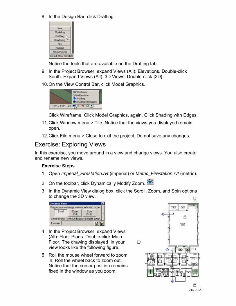
8. In the Design Bar, click Drafting.
Notice the tools that are available on the Drafting tab.
9. In the Project Browser, expand Views (All): Elevations. Double-click South. Expand Views (All): 3D Views. Double-click {3D}.
10. On the View Control Bar, click Model Graphics.
Click Wireframe. Click Model Graphics, again. Click Shading with Edges.
11. Click Window menu > Tile. Notice that the views you displayed remain open.
12. Click File menu > Close to exit the project. Do not save any changes.
Exercise: Exploring Views In this exercise, you move around in a view and change views. You also create and rename new views.
Exercise Steps 1. Open Imperial_Firestation.rvt (imperial) or Metric_Firestation.rvt (metric).
2. On the toolbar, click Dynamically Modify Zoom.
20/213
3. In the Dynamic View dialog box, click the Scroll, Zoom, and Spin options to change the 3D view.
4. In the Project Browser, expand Views
(All): Floor Plans. Double-click Main Floor. The drawing displayed in your view looks like the following figure.
5. Roll the mouse wheel forward to zoom in. Roll the wheel back to zoom out. Notice that the cursor position remains fixed in the window as you zoom.

6. On the toolbar, click Zoom In. Drag a box around the lower building to zoom in on it.
7. Notice the section symbol running vertically through the middle of the
building. This section is named Section 1. In the Project Browser, expand Views (All): Sections. Double-click Section 1 to make that view active.
8. Notice the callout symbol on the right of the building. This callout is named
Callout of Section 1. Move the cursor over the callout to highlight it.
21/213

Right-click the callout. Click Go to View to make Callout of Section 1 the active view.
9. In the Project Browser, expand Views (All): Floor Plans. Right-click Main
Floor. Select Duplicate. A new view named Copy of Main Floor is displayed in the Project Browser.
10. Right-click Copy of Main Floor. Select Rename. In the Rename View dialog box, in Name, enter Main Floor - Furniture Plan. Click OK.
11. Make a second copy of Floor Plan: Main Floor; however, select Duplicate with Detailing instead of Duplicate. Rename the new copy Main Floor-Annotated.
12. Compare the Main Floor - Furniture Plan duplicate to the Main Floor - Annotated duplicate. Notice that the door, window, and room tags are visible in Main Floor - Annotated but not in Main Floor - Furniture Plan.
13. Click Window menu > Tile to display all open views. Click a view's window to make it active.
Exercise: Exploring View Properties In this exercise, you change the properties of a view.
Exercise Steps 1. In the 3D view window, click Maximize. This view fills the frame and is
made the active view.
22/213

2. Zoom in on the building with the pitched roof.
3. On the View Control bar, click Model Graphics Style.
Click Wireframe. The view looks like the following illustration.
4. Cycle through the other Model Graphics Style options, observing the
results, until you return to Shading with Edges. 5. On the View Control Bar, click Shadows. Click Shadows On.
23/213

The building model looks like the following illustration.
6. Notice that the button has changed to reflect the new condition.
Click Shadows, again. Click Shadows Off.
7. In the Project Browser, expand Views: Floor Plans. Double-click Main Floor to make this view active.
8. Enter ZF to fit the view to the view window.
9. On the toolbar, click Fine Lines. 10. Select one of the exterior walls.
24/213
11. On the View Control Bar, click Hide/Isolate.
Click Isolate Category. The view looks like the following illustration.

12. On the View Control Bar, click Hide/Isolate, again. Click Reset Temporary Hide/Isolate.
The view returns to its previous state.
13. On the View Control Bar, click Hide/Isolate. Click Isolate Object. The view looks like the following illustration.
14. On the View Control Bar, click Hide/Isolate, again.
Click Reset Temporary Hide/Isolate. The view returns to its previous state.
15. On the toolbar, click Zoom In. Drag a box around the lavatory room in the upper-left corner of the lower building to zoom in on this area.
16. On the View Control Bar, click Detail Level.
Click Fine.
25/213

17. Notice the additional detail in the walls.
18. On the View Control Bar, click Model Graphics Style.
Click Shading with Edges.
19. Notice the shading in the walls.
20. On the View Control Bar, click Scale.
Click 1/4" = 1'-0" [metric: 1:50]. The view zooms out automatically to the full extents.
21. Zoom in, again, on the lavatory. Notice that the size of the labels and tags is changed relative to the scale of the building model view, which is twice as large as before.
22. Click File menu > Close to exit the project. Do not save any changes.
26/213

27/213

Chapter 4: Starting a Design
• Exercise: Starting a New Project
• Exercise: Using Building Maker for Conceptual Design (Creating the Basic Mass)
• Exercise: Creating Levels
• Exercise: Creating a Column Grid
Exercise: Starting a New Project Exercise Steps 1. Click File menu > New > Project.
In Create New, select Project. Click OK to create a new project.
2. In the Project Browser, expand all branches of Views (All).
Notice that Level 1 is in boldface, indicating that you are in that view.
3. In the Project Browser, expand Views (All): Elevations. Double-click South to change the view. Notice that two levels, Level 1 and Level 2, are defined for you.
28/213

4. In the Project Browser, expand Views (All): Floor Plans. Double-click Site to change to that view. Click File menu > Import/Link > DWG, DXF, DGN, SAT. Navigate to the Training folder. Select Site Model.dwg. Accept the default settings. Click Open. Enter ZF to zoom out to see the entire model.
5. On the Design Bar, right-click. Click Site. 6. On the Site tab, click Toposurface. Click Use Imported.
In the View window, place the cursor over the imported toposurface to highlight it. Click to select it.
7. In the Add Points from Selected Layers dialog box, clear all the layers check boxes except C-TOPO_MAJR. Click OK.
8. Click Finish Surface. On the Toolbar, click Default 3D View. The toposurface looks like the following illustration.
9. Click File menu > Close to exit the project. Do not save any changes.
Exercise: Creating the Basic Mass You are creating the concept for a new building. You have basic parameters for the footprint, height, and form, and you want to quickly develop a conceptual design. In this exercise, you develop a first-concept model using massing.
Exercise Steps 1. Open i_Massing_Start.rvt (imperial) or m_Massing_Start.rvt (metric). 2. On the Design Bar, Massing tab, click Create Mass. If the message “Show
mass” is displayed, click OK. 3. In the Name dialog box, enter Building. Click OK. 4. On the Design Bar, click Solid Form > Solid Extrusion. The Design Bar
changes to display only a Sketch tab. 5. In the Project Browser, under Views (All), Floor Plans, if Level 1 is not in
bold, double-click Level 1.
29/213

6. On the Design Bar, click Lines:
• On the Options Bar, for the Depth value, enter 100’ 0” [30000 mm].
• Click Rectangle.
• Draw a square 90’ 0” [27000mm] on each side.
TIP: Zoom in so that the distance can snap to 90’ 0” [27000mm].
7. On the Design Bar, click Extrusion Properties.
• In Material, click the Value box.
• Click the down arrow. From the Name list, select Default Mass.
• Click OK twice. 8. On the Design Bar, click Finish Sketch. 9. On the toolbar, click Default 3D View.
On the View Control Bar, click Model Graphics Style. Select Shading with Edges.
The massing shape looks like the following illustration.
10. In the Project Browser, expand Views (All), Floor Plans. Double-click Level
1 to change the view back to the Level 1 plan.
30/213

11. On the Design Bar, click Void Form > Void Extrusion: • With the Lines tool, click in the lower-right corner of the mass square to
start a line. • Sketch the line up 30’ 0” [9000mm].
12. Continue sketching a line 30’ 0” [27000mm] to the left, 30’ 0” [9000mm]
down, and 30’ 0” [9000mm] right. 13. On the Design Bar, click Extrusion Properties. For the Extrusion End
constraint value, enter 30’ 0” [9000mm]. Click OK. 14. On the Design Bar, click Finish Sketch. 15. In the Project Browser, expand Views (All), 3D Views. Double-click {3D}.
The massing shape looks like the following illustration.
16. In the Project Browser, expand Views (All), Floor Plans. Double-click Level
4 to change the view to the Level 4 plan. 17. On the Design Bar, click Void Form > Void Extrusion. With the Lines tool,
starting in the lower-left corner of the mass square, sketch a square 45’ 0” [13500mm] right and 45’ 0” [13500mm] up.
31/213

18. On the Design Bar, click Extrusion Properties.
• z For the Extrusion End constraint value, enter 70’ 0” [21000mm].
• z Click OK.
• z Click Finish Sketch. 19. In the Project Browser, expand Views (All), 3D Views. Double-click {3D}.
The massing shape looks like the following illustration.
20. In the Project Browser, expand Views (All), Floor Plans. Double-click Level
4 to change the view back to the Level 4 plan. 21. On the Design Bar, click Void Form > Void Blend:
• Using the Lines tool, starting in the lower right corner of the massing shape, sketch a rectangle 30’ 0” [9000mm] up, 1” [25mm] left, 30’ 0” [9000mm] down, and 1” [25mm] right.
• Zoom in to draw the top and bottom lines.
TIP: On the toolbar, click Thin Lines to reduce the view width of the sketched lines so that you can see to draw a narrow rectangle.
22. On the Design Bar, click Edit Top. Using the Lines tool, starting in the lower-right corner of the massing shape, sketch a rectangle 30’ 0” [9000mm] up, 15’ 0” [4500mm] left, 30’ 0” [9000mm] down, and 15’ 0” [4500mm] right.
23. On the Design Bar, click Blend Properties.
• For the Second End constraint value, enter 70’ 0” [21000mm].
• Click OK.
• Click Finish Sketch.
32/213

24. In the Project Browser, expand Views (All), 3D Views. Double-click {3D}. The massing shape looks like the following illustration.
Exercise: Creating the Mass Details In this section of the exercise you create the details of the mass.
Exercise Steps 1. In the Project Browser, expand Views (All), Floor Plans. Double-click Level
4 to change the view back to the Level 4 plan. Zoom in on the lower-right corner of the massing shape, so the narrow rectangle you sketched in step 21 fills the height of the view window.
2. On the Design Bar, click Void Form > Void Extrusion. Using the Lines tool, starting at the lower-left corner of the narrow rectangle, sketch a rectangle 30’ 0” [9000mm] up, 10’ 0” [3000mm] left, 30’ 0” [9000mm] down and 10’ 0” [3000mm] right.
3. On the Design Bar, click Extrusion Properties.
• For the Extrusion End constraint value, enter 8’ 0” [2450mm]
• For the Extrusion Start constraint value, enter 3’ 6” [105mm].
• Click OK.
• Click Finish Sketch. 4. In the Project Browser, expand Views (All), Elevations. Double-click South
to change the view to the south elevation.
33/213

Move the cursor over the notch in the right side of the outline until it is highlighted. Click to select it.
5. On the toolbar, click Copy.
On the Options Bar, clear Constrain. Select Copy. Select Multiple.
6. Move the cursor over the end of the vertical diagonal line.
When the square Endpoint snap symbol is displayed, click to set the start point.
7. Move the cursor up to the intersection of the vertical diagonal line and the
next higher level line. When you see the X Intersection snap symbol, click to place a copy.
34/213

8. Place five more copies, one on each level above the one where you just placed a copy. Click Modify to end copying. A total of seven notches are created in the vertical diagonal line.
9. In the Project Browser, expand Views (All), 3D Views. Double-click {3D}.
The massing shape looks like the following illustration.
10. In the Project Browser, expand Views (All), Floor Plans. Double-click Level
4 to change the view back to the Level 4 plan. 11. On the Design Bar, click Void Form > Void Extrusion.
Using the Lines tool, starting at the left end of the line perpendicular to the left side of the massing shape, sketch an L-shape 30’ 0” [9000mm] to the right, 10’ 0” [3000mm] up, 20’ 0” [6000mm] left, 5’ 0” [1500mm] up, 10’ 0” [10500mm] left, and 15’ 0” [4500mm] down.
35/213

The shape looks like the following illustration.
12. On the Design Bar, click Extrusion Properties.
• For the Extrusion End constraint value, enter 8’ 0” [2450mm]
• For the Extrusion Start constraint value, enter 3’ 6” [105mm].
• Click OK.
• Click Finish Sketch. 13. In the Project Browser, expand Views (All), Elevations. Double-click West
to change the view to the west elevation. As in steps 28 through 32, copy this void six times to the next higher levels, as shown in the following illustration. Start at the lower end of the central vertical line, just above the arrow in the illustration.
36/213

14. In the Project Browser, expand Views (All), 3D Views. Double-click {3D}. The massing shape looks like the following illustration.
15. Click Finish Mass.
Exercise: Converting the Mass to Building Elements In this section of the exercise you convert the mass to building elements.
Exercise Steps 1. In the view window, select the massing form:
• On the Options Bar, click Floor Area Faces.
• In the Floor Area Faces dialog box, select all of the levels except for Level 11.
• Click OK.
• Clear the selection of the mass form.
The shape looks like the following illustration.
shape looks like the following illustration.
37/213

2. In the Project Browser, expand Views (All), Elevations. Double-click East to change the view to the east elevation. On the Design Bar, click Floor by Face. In the east elevation, select all of the levels except for the top level.
3. On the Options Bar, click Create Floors.
In the Project Browser, expand Views (All), 3D Views. Double-click {3D}. The mass shape looks like the following illustration.
4. On the Design Bar, click Roof by Face. Select the two upper horizontal surfaces. On the Options Bar, click Create Roof.
38/213

5. On the Design Bar, click Curtain System by Face. Select the east face of the building form.
6. On the Options Bar, click Create System.
The massing shape looks like the following illustration.
7. Continue replacing massing faces with building elements:
• Replace the north face, the south face of the north tower (which extends west under the overhanging balconies), and the west face of the upper-south-projecting wing with walls.
• Replace all other exterior faces with curtain walls.
39/213

TIP: Rotate the 3D model so that you can select and convert different faces of the mass.
The completed building model looks like the following illustration.
8. Click File menu > Save As, and enter a file name to save your design.
Click File menu > Close to close the project. Do not save changes.
Exercise: Creating Levels In this exercise, you create levels to control the vertical extent of the foundation, building walls, and roofs.
Exercise Steps 1. Open i_Firestation_Levels.rvt (imperial) or m_Firestation_Levels.rvt
(metric). 2. In the Project Browser, expand Views (All): Elevations. Double-click East
to change the view to the east elevation.
40/213

3. Click View menu > Visibility/Graphics. In the Visibility/Graphics dialog box, DWG/DXF/DGN Categories tab, clear the SiteModeling.dwg check box to turn off the display of the imported AutoCAD site model. Click OK.
4. The two lines in the lower center of the site model are the default level
lines.
On the toolbar, click Zoom In. Drag a box around the right end of the level lines to zoom in on them.
5. Click the horizontal line of the upper level line to select it.
Right-click on the level line. Click Maximize 3D Extents.
6. Repeat Step 5 for the lower level line. Enter ZF to zoom out to the full extents of the building model. Your view looks like the following illustration, where both level lines extend the width of the hatched area.
7. Zoom in on the right end of the level lines. 8. Select Level 2. Highlight and click the blue Level 2 name. Enter T.O.
Footing as the new level name. When prompted to change the names of the corresponding views, click Yes.
41/213

9. Highlight and click the blue 10' 0" elevation. Enter 126' [38400mm] as the new level height. The level line moves to this height.
10. Select Level 1. Change the level name to Ground Floor. When prompted
to change the names of the corresponding views, click Yes. Change the level height to 130' [39600mm]. The level line moves to this height.
11. Enter ZF to zoom out. Zoom in on the upper-right corner of the hatched area.
12. On the Design Bar, Basics tab, click Level. Place the cursor over the
upper level line near the left edge of the view window. Move up 10' 0" [4000mm]. Click to place the tail of the new level line.
Drag the level line to the right until it is over the head of the Ground Floor level. A vertical green dashed line is displayed. Click to place the head of the new level line.
42/213

13. On the Design Bar, click Modify. Select the level line you just drew. Change its name to Main Floor. When prompted to change the names of the corresponding views, click Yes. Change its height to 140' [43600mm] if it is different. With the level line still selected, right-click on the level line. Click Maximize 3D Extents.
14. Using the same techniques as in the preceding steps, add three levels. Their names and heights are
• Lower Roof, 150' [47600mm]
• Main Roof, 160' [51600mm]
• T.O. Parapet, 164' [52800mm]. When prompted to change the names of the corresponding views, click Yes.
15. The levels look like the following illustration.
16. Enter ZF to zoom out to the full extents of the model. 17. Click File menu > Close to exit the project. Do not save any changes.
Exercise: Creating a Column Grid In this exercise, you create a grid to control the placement of columns.
Exercise Steps 1. Open i_Firestation_Grids.rvt (imperial) or m_Firestation_Grids.rvt (metric). 2. In the Project Browser, expand Views (All): Floor Plans. Double-click
Ground Floor to change to that view.
3. On the toolbar, click Zoom In.
43/213

Drag a selection box around the upper green rectangular outline. Click to zoom in on this area.
4. On the Design Bar, Basics tab, click Grids. 5. On the Options Bar, click Pick. Set Offset to 2' 0" [600mm].
44/213
6. Move the cursor from the inside toward the left side of the green rectangle. When a dashed line is displayed, click to place a grid line.
7. Repeat step 6 to add grid lines to the
upper, right, and lower-right sides of the green rectangle.
8. On the Options Bar, select Draw. Set Offset to 0' 0" [0mm].

Add two more horizontal grid lines and one more vertical grid line as shown in the following illustration:
• Click to place the tail of the grid line.
• Sketch the line.
• Click to place the head.
9. On the Design Bar, click Modify. Select the left vertical grid line. Clear the
blue check box below the line and select the check box above the line to switch the head from the lower end to the upper end of the line.
45/213

10. Click the open circle at the base of the grid-line head. Drag the head up until it is aligned with the head to its right, as shown by a green dashed line. Click to place the head.
NOTE: If you accidentally click on the Split Line indicator, click Edit menu > Undo Move.
11. Click the open circle at the lower end of the grid line. Drag the tail of the grid line down. Click to place it.
12. Using the steps 9 through 11, resize the remaining grid lines to look like
the following illustration.
13. Select the upper horizontal grid line. Click the blue number in the head.
Change the number to A. Repeat for the other three horizontal grid lines, naming them B, C, and D.
14. Select the left vertical grid line. Click the blue number in the head. Change the number to 1. Repeat for the other two vertical grid lines, naming them 2 and 3.
46/213

15. On the Design Bar, Basics tab, click Dimension. Place a dimension below the vertical grid lines from the left line to the center line and to the right line.
16. Click on the blue EQ with the slash through it that is above the dimension
line.
The slash disappears, and both dimensions are set to EQ (equal). The center line moves into position halfway between the outer lines.
17. Click the two blue padlocks below the dimension line to lock the dimensions.
18. Add a vertical dimension from the right end of the lower green line up to
the lower horizontal grid line and up to the next two grid lines. Click on the lower padlock to lock that dimension.
47/213

19. On the Design Bar, click Modify. Click the middle horizontal grid line to select it. Click the lower blue dimension number to edit it.
Change the value to 19' 0" [5500mm].
20. Click the upper horizontal grid line to select it. Click the upper blue dimension number to edit it. Change the value to 19' 0" [5500mm]. The grid lines are now named and correctly positioned .
Exercise: Adding Columns to the Grid In this exercise, you add columns at grid intersections.
Exercise Steps 1. If the Structural tab on the Design Bar is not visible, right-click the Design
Bar. Click Structural. 2. On the Design Bar, Structural tab, click
Structural Column. In the Type Selector, select Concrete - Square - Column: 24 x 24 [M_ Concrete - Square - Column: 600 x 600].
48/213

3. On the Options Bar, select Place By: Grid Intersection.
4. In the view window, click below and right of the intersection of grid line D
and grid line 3. Drag a selection box up and left until all of the grid lines are within the selection box.
Columns are displayed at each grid intersection.
5. On the Options Bar, click Finish. The completed grid of columns looks like the following illustration.
6. Click File menu > Close to exit the project. Do not save any changes.
49/213

Chapter 5: Creating a Building
• Exercise: Creating and Modifying Walls
• Exercise: Creating Compound Walls
• Exercise: Adding Interior Walls
• Exercise: Creating and Using Vertically Compound Walls
• Exercise: Adding Doors
• Exercise: Working with Windows
Exercise: Adding Walls In this exercise, you add the walls to the fire station. The site in this exercise already includes two building pads.
Exercise Steps 1. Close any open projects. Open i_Firestation_Walls1.rvt (imperial) or
m_Firestation_Walls1.rvt (metric). 2. In the Project Browser, expand Views (All): Floor Plans. Double-click
Ground Floor to make that view active.
3. On the toolbar, click Zoom In. Drag a selection box around the lower green rectangular outline to zoom in on that area, where you add the walls.
4. On the Design Bar, Basics tab, click Wall.
In the Type Selector, select Basic Wall: Generic - 6" [Basic Wall: Generic - 150mm].
50/213

5. On the Options Bar, click Draw. On the Options Bar, Location Line, select Core Face: Exterior.
On the Options Bar, click Rectangle.
6. In the view window, position the cursor over the upper-left corner of the green rectangle. When a square endpoint snap box is displayed, click to start drawing the walls.
7. Drag the rectangular walls down and right to the lower-right corner of the
green rectangle.
Click to finish drawing the walls.
8. On the toolbar, click Default 3D View. The walls look like those in the following illustration.
51/213

9. In the Project Browser, expand Views (All): Floor Plans. Double-click Ground Floor to return to that view.
10. On the Design Bar, Basics tab, click Wall. In the Type Selector, select Basic Wall: Foundation -12" Concrete [Basic Wall: Foundation -300mm Concrete].
11. When creating foundation walls, the top of the wall is set to the current level by default. You then set the depth of the foundation wall. In this case, the base of the foundation wall is located on Level T. O. Footing. On the Options Bar, Depth, select T. O. Footing.
Make sure Location Line is set to Core Face: Exterior. On the Options Bar, click Rectangle.
12. Starting to the left and above the upper-left corner of the rectangular walls you placed in step 7, move the cursor over the corner of the walls. When a square endpoint snap box is displayed on the exterior corner of the wal, click to start drawing the foundation walls. Drag the rectangular walls down and right to the lower-right corner of the existing walls. Click to finish drawing the foundation walls.
13. Because the new wall is below the view extents (View Range) of the current Ground Floor plan view, a warning message is displayed.
Close the warning.
Exercise: Creating a New Wall Type By Modifying an Existing Type
Exercise Steps 1. In the project Browser, expand Views (All): Floor Plans. Double-click T. O.
Footing to change to that view. 2. On the Design Bar, Basics tab, click Wall.
In the Type Selector, select Basic Wall: Foundation -12" Concrete [Basic Wall: Foundation -300mm Concrete].
3. On the Options Bar, click Properties.
52/213

4. In the Element Properties dialog box, click Edit/New.
In the Type Properties dialog box, click Duplicate.
5. In the Name dialog box that appears, enter Footing in the Name field.
Click OK to create a duplicate copy of the 12" Concrete [300mm Concrete] Foundation wall.
6. To modify the new wall type to increase its width. In the Type Properties dialog box, in the Value column of the Structure parameter row, click the Edit button. In the Layers group of the Edit Assembly dialog box, click in the Thickness field of row 2 (Structure). Change the Thickness value from 1' 0" [300mm] to 2' 0" [600mm].
Click OK to close the Edit Assembly dialog box. Click OK twice to close the Type Properties and Element Properties dialog boxes.
7. On the Options Bar, set the Depth to Unconnected and the depth value to 1' 6" [450mm].
In the Location Line drop list on the Options Bar, select Wall Centerline. On the Options Bar, click Rectangle.
8. So you can see the wall that you will draw in the following step, change the view range for the active view. Right-click in the view window. In the shortcut menu, click View Properties. In the Instance Parameters group of the Element Properties dialog box, scroll down until you can see the View Range Parameter. In the Value column of the View Range row, click the Edit button.
53/213

In the View Depth group of the View Range dialog box, set the Level to Unlimited.
Click OK twice.
9. Sketch the footing by snapping the rectangle to the centerline at the upper-left and lower-right corners of the foundation. You need to zoom in on these corners of the foundation so you can pick the wall centerline.
10. Create a Section view so you can see the details of the footing and
foundation walls. On the Basics tab of the Design Bar, click Section. Using the illustration below, place a section across the middle of the building. Starting below the lower wall, click. Extend the section line up above the upper wall. Click to create the section.
11. Place the cursor over the section line. Right-click. In the shortcut menu,
click Go To View to change the active view to the section.
54/213

Your section view should look like the illustration below.
Exercise: Modifying the Existing Walls Exercise Steps 1. In the Project Browser, expand Views (All): Floor Plans. Double-click
Ground Floor to return to that view. 2. On the Design Bar, click Modify. In the view window, select the upper
horizontal wall. This wall should be Basic Wall: Generic -6" [Basic Wall: Generic - 150mm].
3. To raise the base of this wall to the Main Floor level so that it is above
grade: On the Options Bar, click Properties. Change the value of Base Constraint to Main Floor. Click OK. The wall is no longer displayed in the Ground Floor plan view.
4. To split the side wall so a portion of that wall can be raised to the Main
Floor level: On the toolbar, click Split. Using the following image as a guide, zoom in on the upper part of the west (left) wall and split the wall 10' 0" [3000mm] from the top (north). Be sure this wall is set to Basic Wall: Generic - 6" [Basic Wall: Generic - 150mm].
5. Using the technique in the previous step, split the right (east) Basic Wall:
Generic - 6" [Basic Wall: Generic - 150mm] wall 10' 0" [3000mm] from the top (north) end.
55/213

6. On the Design Bar, click Modify. In the view window, select both of the 10' 0" [3000mm] wall segments that were created as a result of the split. Press CTRL to make multiple selections.
7. On the Options Bar, click Properties.
In the Element Properties dialog box, Base Constraint, select Main Floor. Click OK to update the walls.
8. On the toolbar, click Default 3D View. The walls look like those in the following illustration.
9. In the 3D view, select the long foundation wall as shown in the following
illustration.
10. On the Options Bar, click Properties.
In the Element Properties dialog box, Top Constraint, select Up to Level: Main Floor.
56/213

Click OK to update the wall.
11. Select the west foundation wall as shown in the following illustration.
12. On the Options Bar, click Attach. A new Options Bar is displayed.
Make sure Attach Wall: Top is selected.
13. Select the upper wall that is
raised above the foundation wall (its type is Basic Wall: Generic - 6" [Basic Wall: Generic - 150mm]). The foundation wall joins to this wall.
57/213

14. Repeat steps 11 through 13 for the east foundation wall. You can rotate the view to make it easier to select the east foundation wall. The completed exercise looks like the following illustration.
15. Click File menu > Close to exit the project. Do not save any changes.
Exercise: Creating Compound Walls In this exercise, you modify the structure of the basic walls on the main floor of the fire station. The walls are made of a wood stud layer, clapboard siding exterior, and gypsum wall board interior.
Exercise Steps 1. Open i_Firestation_CompoundWalls.rvt (imperial) or
m_Firestation_CompoundWalls.rvt (metric). 2. In the Project Browser, expand Views (All): Floor Plans. Double-click
Ground Floor to make that view active.
3. On the toolbar, click Zoom In. Drag a selection box around the lower green rectangular outline to zoom in on that area. You add walls there.
58/213

4. In the view window, select the south Basic Wall: Generic - 6" [Basic Wall: Generic - 150mm] wall.
Look in the status bar to ensure that you have selected the right type of wall.
5. On the Options Bar, click Properties. 6. In the Element Properties dialog box, click Edit/New. In the Type
Properties dialog box, click Duplicate. 7. In the Name dialog box, enter Exterior - Siding in the Name box.
Click OK to create a duplicate copy of the Generic - 6" [Generic - 150mm] wall named Exterior - Siding.
8. In the Type Properties dialog box, Structure, under Value, click Edit. In the Edit Assembly dialog box, in the Layers Group, under Material in row 2 Structure [1], click Default Wall, or (whichever appears). Click the down arrow.
9. In the Materials dialog box, Name, select Wood - Stud Layer.
Click OK.
10. In the Edit Assembly dialog box, under Layers, row 2 (Structure), click Thickness. Change the thickness value from 0' 6" [150mm] to 0' 5 1/2" [140mm].
59/213

11. In the Edit Assembly dialog box, under Layers, select row 1. Click Insert to add new layers to the wall type.
12. Click Function of the new row. From Function, select Substrate [2].
13. Set the value of the Material field to Wood - Sheathing - plywood.
Set Thickness to 0' 0 3/4" [20mm]. Click OK.
14. Select the Substrate [2] layer, again. Click Insert to add another new layer above (toward the exterior) the substrate layer.
15. Select the new row. Set the Function of the new layer to Membrane Layer, the Material to Air Barrier - Air Infiltration Barrier. Click OK. The Thickness should remain 0.
16. Select the Membrane layer, again. Click Insert to add another new layer above (toward the exterior) the membrane layer.
17. Select the new row. Set Function of the new layer to Finish 1, Material to Finishes - Exterior - Siding / Clapboard, and Thickness to 0' 0 1/2" [13mm].
18. Using the techniques from the previous steps, select the lowest row and insert two additional layers. If necessary, move them to the interior side of the wall (bottom of layer list) using the Down button.
19. Select the upper row of the two new rows. Set Function of the new layer to Membrane Layer, Material to Vapor/Moisture Barriers - Damp-proofing, and Thickness to 0' 0" [0mm].
20. Select the lower row of the two new rows. Set Function of the new layer to Finish 2, Material to Finishes - Interior - Gypsum Wall Board [metric: Finishes - Interior - Plasterboard], and Thickness to 0' 0 5/8" [16mm].
60/213
21. Click OK to close the Edit Assembly dialog box. Click OK twice to close the Type Properties and Element Properties dialog boxes. The wall selected in step 4 (at the beginning of this process) is changed to the new wall type you just created.

22. In the Project Browser, expand the Families branch. Expand Walls. Expand Basic Wall. Right-click Generic - 6" [Generic - 150mm] wall type. Click Select All Instances to change all instances of the Basic Wall: Generic - 6" [Basic Wall: Generic - 150mm] walls.
23. In the Type Selector, select Basic Wall: Exterior - Siding. 24. In the Project Browser, double-click Section 1 to change to this view and
display the changes.
Notice that the upper walls are now thicker and hang over the exterior face of the foundation wall.
25. Click File menu > Close to exit the project. Do not save any changes.
61/213

Exercise: Adding Interior Walls In this exercise, you add walls to the ground floor of the Administrative Building. You modify an existing wall type and split a wall, replacing part of the wall with a new type.
Exercise Steps 1. Open i_Firestation_InteriorWalls.rvt (imperial) or
m_Firestation_InteriorWalls.rvt (metric). 2. In the Project Browser, expand Views (All): Floor Plans. Double-click
Ground Floor to make that view active.
3. On the toolbar, click Zoom In. Drag a selection box around the lower building outline to zoom in on that area. You are adding interior walls within that building.
4. On the Design Bar, Basics tab, click Wall. In the Type Selector, select
Basic Wall: Interior - 4 7/8" Partition (1-hr) [Basic Wall: Interior - 123mm Partition (1-hr)]. You might see an error message that the top of the wall is lower than the base of the wall. You get this message because the previously selected footing wall measures down rather than up for its second constraint. In the error dialog box, click Reset Constraints to set the wall constraints back to the default conditions. You will need to reselect the Basic Wall: Interior - 4 7/8" Partition (1-hr) [Basic Wall: Interior - 123mm Partition (1-hr)]. On the Options Bar, Height, select Main Floor.
Make sure Chain is cleared and the Line tool is selected.
62/213

5. On the Options Bar, Location Line, select Wall Centerline.
6. To draw a horizontal wall 20' [6100mm] up from the lower wall:
Starting at the lower-left corner of the room, move the cursor up along the west (left) wall. Tracking dimensions are displayed.
Enter 20 [6100] while the tracking dimensions are visible. The dimension is displayed in a box over the tracking dimension.
Press ENTER. The start of a wall is placed 20' [6100mm] up from the centerline of the lower wall.
7. Drag the right end of the new wall horizontally across to the right wall of the building. Click to place the end of the wall.
8. Add a second wall perpendicular to the last wall created and intersecting
the south wall near its left end. The exact location is not critical. This wall also is part of the stairwell definition.
63/213

9. The distance between the new wall and the centerline of the west (left) exterior wall is 10' - 9 9/16" [3289mm]. To position the new wall at this dimension, click the blue dimension number that is displayed below the wall after you placed it.
Enter 10' 9 9/16" [3289mm].
Press ENTER. The wall snaps to the new position. 10. Add another wall in the lower-right corner of the building that is 10' 9 9/16"
[3289mm] from that corner.
11. Draw a horizontal wall between
the two walls you placed in steps 8 through 10 that is 6' 0" [1800mm] below the wall you placed in step 7.
64/213

12. Using the following illustration as a guide, place four walls between the last wall and the lower exterior wall of the building. The center-to-center distances, from left to right, are 14' 0", 11' 0", 11' 0" 17' 8", and 11' 0" [4300mm, 3400mm, 3400mm, 5215mm, and 3400mm].
13. Place five vertical and two horizontal walls above the wall of step 7, as
shown in the following figure. The center-to-center distances from left to right of the vertical walls are 17' 6", 10' 0", 14' 0", 15' 0", 14' 0", and 15' 2" [5300mm, 3000mm, 4300mm, 4600mm, 4300mm, and 4616mm]. The left horizontal wall is 6' 5" [2000mm] up from the central horizontal wall and the right horizontal wall, 10' 6" [3200mm].
14. On the Design Bar, Basic tab, select Wall.
In the Type Selector, make sure Basic Wall: Interior - 4 7/8" Partition (1-hr) [Basic Wall: Interior - 123mm Partition (1-hr)] is selected. On the Options Bar, click Properties.
15. In the Element Properties dialog box, click Edit/New.
In the Type Properties dialog box, click Duplicate. In the Name dialog box, enter Interior - Plumbing Chase. Click OK.
65/213

16. In the Type Properties dialog box, Structure row, Value column, click Edit. Using the techniques learned in the previous lesson, insert two additional wall layers in the core boundary. Modify the layer thickness settings as shown in the following [metric: use 16mm, 92mm, 120mm, 92mm, and 16mm, for a total wall thickness of 336mm]:
In each of the three open dialog boxes, click OK.
17. In the Type Selector, make sure the new wall type, Basic Wall: Interior - Plumbing Chase, is selected. In the room located in the upper-left corner of the building, sketch a wall type horizontally across the room using the new type. The exact position of this wall is not critical.
18. On the Design bar, click Modify
To position the new wall using the Align tool,
On the Toolbar, click Align. On the Options Bar, make sure Prefer: Wall Faces is selected.
66/213

With the Align tool, select the lower end of the vertical foundation wall.
Select the lower face of the horizontal plumbing chase wall.
The horizontal wall snaps into alignment with the end of the vertical wall.
19. On the Design Bar, Basics tab, click Wall.
In the Type Selector, select Basic Wall: Interior - 4 7/8" Partition (1-hr) [Basic Wall: Interior - 123mm Partition (1-hr)].
67/213

Sketch the dimensioned wall as shown in the following illustration.
20. To use the Split tool will be used to remove a section of wall
On the Toolbar, click Split. On the Options Bar, select Delete Inner Segment. This option removes the segment between the two locations being split.
Using the following illustration as a guide, move the cursor to the lower end of the wall that was placed in step 19. Click to split the horizontal wall.
Repeat on the right intersection. When finished, the segment between the two splits is deleted.
21. With the Split tool still active,
move the cursor to the upper end of the wall placed in Step 19. Click to split the horizontal Plumbing Chase wall. Make only one split, so no wall segment is deleted.
68/213

22. On the Design Bar, click Modify. Select the right section of the wall you just split.
In the Type Selector, select Basic Wall: Interior - 4 7/8" Partition (1-hr) [Basic Wall: Interior - 123mm Partition (1-hr)]. The wall section changes to this type.
23. Because the new type of the wall section is not the same width as the old type, you need to align the faces of the wall's sections.
On the toolbar, click Align. Select the upper face of the left wall section.
Select the upper face of the right section.
The faces snap into alignment.
24. The Ground Floor plan of the building looks like the following illustration.
25. Click File menu > Close to exit the project. Do not save any changes.
69/213

Exercise: Create a Copy of a Wall Type In this exercise, you create and modify vertically compound walls. You define wall structure vertically, in sections, in addition to plan structure. Wall structure can include sweeps and reveals. Layers can extend beyond other layers at top and bottom, or span across layers below or above.
Exercise Steps 1. Open i_Firestation_VertCpdWalls.rvt (imperial) or
m_Firestation_VertCpdWalls.rvt (metric). 2. On the Design bar, Basics tab, click Wall.
From the Type Selector, select Basic Wall : Exterior - Brick on Mtl. Stud. Click Properties.
3. In the Element Properties dialog box, click Edit / New. In the Type Properties dialog box, click Duplicate to create a copy of the wall type. In the Name field, enter Exterior - Brick and CMU. Click OK.
4. In the Type Properties dialog box, in the Structure row, under Value, click Edit.
5. In the Edit Assembly dialog box, click Preview to display the preview pane.
6. In the View list, select Section: Modify Type Attributes to change the
preview to a section view.
70/213

7. Right-click anywhere in the preview window. Click Zoom In Region. Zoom in on the bottom part of the wall.
8. In the Edit Assembly dialog box, under Modify Vertical Structure, click Split
Region. Place the cursor along the left layer of the wall. Click to split the region into two parts. As you split the region, dimensions are displayed that show where the split occurs.
Notice that both regions have the same material as the original layer and that in the table the Thickness setting for Layer 1 is now set to Variable. After a layer is split, the thickness is no longer recorded as a fixed value.
9. In the Edit Assembly dialog box, under Modify Vertical Structure, click Modify to modify the position of the split. Position your cursor over the split. When it is highlighted, click to select it. Click on the temporary dimension. Change the value to 3' 6" [1050mm]. Press ENTER.
71/213

Exercise: Assign a Material to a Layer Exercise Steps 1. In the Edit Assembly dialog box, Layer list, click Layer 1 to highlight that
row. Click Insert to add a new wall layer at the top of the list.
2. From the Function list, select Finish 1 [4].
From the Material list, select Masonry - Concrete Masonry Units. Click OK. Notice that the thickness is set to 0.
3. In the Layers list, click Layer 1, the new CMU layer, to select that row.
In the Edit Assembly dialog box, under Modify Vertical Structure, click Assign Layers.
4. Position your cursor over the lower section
that you split earlier. Click the region to assign the layer to this region. This region now has the same thickness value as the rest of the layer.
72/213

Exercise: Add a Wall Sweep Exercise Steps
1. In the Edit Assembly dialog box, under Modify Vertical Structure, click Sweeps.
2. In the Wall Sweeps dialog box, click Add to add a wall sweep.
3. Enter new values as follows:
• From the Profile list, select Sill-Precast : 5" Wide [M_Sill-Precast: 125mm Wide].
• From the Material list, select Concrete - Precast Concrete. Click OK.
• In the Distance box, enter 3' 6" [1050mm]. • From the From list, select Base.
• From the Side list, select Exterior.
• In the Offset box, enter 0' 0" [0mm]. Make sure that the Flip checkbox is cleared. Click Apply to see the wall sweep in the preview pane.
4. In the Wall Sweeps dialog box, click Add to add a second wall sweep.
73/213

5. Enter new values as follows:
• From the Profile list, select Wall Sweep-Brick Soldier Course : 1 Brick [Wall Sweep-Brick Soldier Course: 1 Brick].
• From the Material list, select Masonry - Brick Soldier Course. Click OK.
• In the Distance box, type -4' [-1200mm]. • From the From list, select Top.
• In the Offset box, enter --0' 3" [-75mm].
Click Apply to add the sweeps to the wall definition. Scroll up in the preview window to see the added sweep.
6. In the Wall Sweeps dialog box, click Add to add a parapet cap. 7. Enter new values as follows:
• From the Profile list, select Parapet Cap-Precast : 16" Wide [M_Parapet Cap-Precast: 350mm Wide].
• From the Material list, select Concrete - Precast Concrete.
• In the Distance box, enter 0' 0" [0mm]. • From the From list, select Top.
74/213

Click Apply to add the parapet cap.
8. Click OK to close the Wall Sweeps dialog box. 9. In the Edit Assembly dialog box, under Modify Vertical Structure, click
Reveals. 10. Enter new values as follows:
• In the Reveals dialog box, click Add three times to add three reveals.
• From the Profile list, select Reveal-Brick Course: 1 Brick [M_Reveal-Brick Course: 1 Brick] for all three reveals.
• In the Distance box, enter 9' 0" [2700mm] for the first reveal, 11' 0" [3300mm] for the second reveal and 13' 0" [3900mm] for the thirdreveal.
• From the From drop list, select Base for all three reveals.
• From the Side list, select Exterior for all three reveals.
• Notice that Offset is set to -0' 0" [0mm].
Click OK to close the Reveals dialog box. Scroll down in the preview window to see the added reveals.
11. In each open dialog box, click OK to return to the view window.
75/213
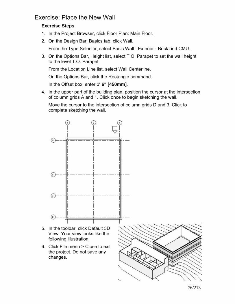
Exercise: Place the New Wall Exercise Steps 1. In the Project Browser, click Floor Plan: Main Floor. 2. On the Design Bar, Basics tab, click Wall.
From the Type Selector, select Basic Wall : Exterior - Brick and CMU. 3. On the Options Bar, Height list, select T.O. Parapet to set the wall height
to the level T.O. Parapet. From the Location Line list, select Wall Centerline. On the Options Bar, click the Rectangle command. In the Offset box, enter 1' 6" [450mm].
4. In the upper part of the building plan, position the cursor at the intersection of column grids A and 1. Click once to begin sketching the wall. Move the cursor to the intersection of column grids D and 3. Click to complete sketching the wall.
5. In the toolbar, click Default 3D View. Your view looks like the following illustration.
6. Click File menu > Close to exit the project. Do not save any changes.
76/213

Exercise: Adding Doors You add an exterior door and various types of interior doors. You load new door types, and you place instances in your model. Exercise Steps
1. Open i_Firestation_Doors.rvt (imperial) or m_Firestation_Doors.rvt (metric).
2. In the Project Browser, expand Floor Plans. Double-click Ground Floor. 3. On the Design Bar, Basics tab, click Door.
From the Type Selector, select the default door family and type shown (Single-Flush 34" x 80" [m_Single-Flush 864 x 2032]).
4. From below the wall, position the cursor on the south exterior wall. Click to add a door.
5. Click the blue number on the
dimension between the door and the wall. Change the dimension value to move the door into position, as shown in the following image.
NOTE: If the door selection is canceled, click Modify to exit the Door command. Select the door.
77/213
6. Click the arrows that are parallel to the wall to flip the hand of the door. Click the arrows perpendicular to the wall to flip the facing of the door so that it opens to the inside. Click the arrows again so that the door opens outward again, as shown in the following figure.

7. On the Design Bar, Basics tab, click Door. From the Type Selector, select Single-Flush: 34" x 84" [m_Single-Flush: 864 x 2134mm]. Position the cursor on an interior wall facing the main hallway as shown in the following figure. Click to add a door. Flip the hand and facing of the door, if you want. Add a second door as shown.
8. Click File menu > Load from Library > Load Family to add a new door
type. In the Imperial Library [Metric Library] folder, navigate to the Doors folder. Click Double-Glass 1.rfa [m_Double-Glass1.rfa].
NOTE: If these door families are not included in the default library folder, navigate to the following folder: C:\Documents and Settings\All Users\Autodesk Learning\Revit Architecture 2008 8\Essentials\Training Library
Click Open to load the additional door type into your project.
9. On the Design Bar, click Modify. Select the first door you added to the project. From the Type Selector, select Double Glass 1: 72" x 84" [m_Double-Glass 1:1830 x 2134mm].
78/213

10. On the Design bar, click Door. On the Options Bar, click Load. In the Imperial Library [Metric Library] folder, navigate back to the Doors folder. Click Single-Flush Vision.rfa [M-Single-Flush Vision.rfa]. Press CTRL and click Single-Glass 1.rfa (M_Single-Glass 1.rfa). Click Open to load both of these door types into your project.
11. On the Design Bar, click Door.
From the Type Selector, select Single-Flush Vision: 36" x 84" [m_Single-Flush Vision: 0915 x 2134mm]. Place the door as shown in the following figure (door #4). Flip the door hand or facing, if you want.
12. Click File menu > Close to exit the project. Do not save any changes.
Exercise: Loading a Window Family and Adding Windows You are designing a fire station and need to place windows in the Administration Building. Your design calls for several windows of different sizes.
Exercise Steps 1. Open i_Firestation_Windows.rvt (imperial) or m_Firestation_Windows.rvt
(metric). 2. In the Project Browser, expand Floor Plans. Double-click Ground Floor. 3. On the Design Bar, Basics tab, click Window.
From the Type Selector, select Window: 24" W [m_Window: 610mm W].
79/213

4. Add one instance of the window to the left side of the south wall, as shown in the following illustration. Modify the temporary dimension value to set the window position 2' 0" [600mm] from the centerline of the dimensioned wall.
5. On the Design Bar, Basics tab, click Window.
From the Type Selector, select Window: 30" W [m_Window: 762mm W]. 6. Add one instance of the window to the left side of the south wall, as shown
in the following illustration. Modify the temporary dimension value to set the window position 2' 0" [600mm] from the centerline of the dimensioned wall.
80/213

Exercise: Create and Add New Window Types Exercise Steps 1. On the Design Bar, Basics tab, click Modify.
Select the last window that you placed. On the Options bar, click Properites.
2. In the Element Properties dialog box, click Edit/New. Click Duplicate. In the Name dialog box, enter 36” W [914 mm W] for Name
Click OK.
3. In the Type Properites dialog box, enter 3’ 0” [914mm] for Width Click OK
4. In the Element Properties dialog box, click OK. The window changes, as shown in the following illustration.
5. Select the window that you just modified.
On the Toolbar, click Copy. In the center of the window, click to select a reference point, as shown in the following illustration.
Move the cursor to the right to select a location for the new window. When the new location is 10 feet [3100mm] from the original window, click to place the copy. Your drawing looks like the following illustration.
81/213

6. Add six additional 36" W [914mm W] windows using the technique in the previous step. Use the image below as a guide for window placement.
7. Click File menu > Close to exit the project. Do not save any changes.
82/213

83/213

Chapter 6: Using Dimensions and Constraints Chapter Exercises
• Exercise: Dimensioning Objects
• Exercise: Applying Constraints
• Exercise Dimensioning Objects In this exercise, you modify the position of walls in a building with dimensions.
Exercise Steps 1. Open i_Dimensions.rvt (imperial) or m_Dimension.rvt (metric). 2. Select the leftmost interior wall as shown.
Temporary dimensions are displayed.
3. Click the dimension symbol to make the dimensions permanent.
84/213

4. Click the dimension line to select it.
5. Move the cursor over the dimension line. Drag it down toward the wall.
Release the mouse button to place the dimension line.
6. Click the control of the left witness line.
The control shifts to the inside face of the left wall. If it shifts to the outer face, click it once more.
7. Click the control of the right witness line until it shifts to the left face of its reference wall.
8. Select the center wall. Temporary dimensions are displayed in addition to the permanent dimensions.
9. Click the left dimension number
of the temporary dimension to edit it. Enter 8' 0" [2400mm]. Press ENTER. The center wall moves left.
85/213

10. Click the right dimension number of the temporary dimension to edit it. Enter 12' 0" [3600mm]. Press ENTER. The center wall moves back right.
11. Select the center of the three interior walls. Edit the left temporary dimension to 10' 0" [3000mm].
Press ENTER. The selected wall moves left.
12. On the Design Bar, Basics tab, click Wall. In the Type Selector, click Basic Wall: Generic -8" [Basic Wall: Generic - 200mm].
13. Move the cursor over the lower-left corner of the building until the centerline of the lower wall highlights.
14. Continue moving the cursor right along the lower wall. Temporary
dimensions are displayed.
15. 15. While the temporary dimensions reference the corner of the building,
enter 12' 0" [3600mm].
Press ENTER. The wall snaps into position at a center-to-center distance of 12' 0" [3600mm].
86/213

16. Move the cursor up to connect the wall with the center horizontal wall.
Click to place the wall.
17. On the Design Bar, Basics tab, click Dimension. On the Options Bar, change the snap preference to Prefer: Wall Faces.
18. Dimension from the right face of the leftmost wall to the left face of the wall
to the right.
19. Continue dimensioning the walls and rooms as shown in the following
illustration. When you reach the left face of the rightmost wall, move the cursor to a blank area of the view window so no wall reference is highlighted.
Click to finish placing dimensions.
87/213

The dimensions look like the following illustration.
20. Click File menu > Close to exit the project. Do not save any changes.
Exercise: Applying Constraints In this exercise you use constraints to align doors at either end of the central corridor with each other and to center the front door with the entry lobby. You also align walls at two different levels.
Exercise Steps 1. Open i_Constraints.rvt (imperial) or m_Constraints.rvt (metric).
2. On the toolbar, click Align. 3. Select the centerline of the door at the left end of the corridor.
4. Select the centerline of the door at the right end of the corridor.
5. Click the padlock to lock the alignment constraint.
88/213

6. On the Design Bar, click Modify:
• Select the door at the left end of the corridor.
• Drag it up or down. Notice that the right door follows in alignment.
• Click to place the door.
• Click Edit menu > Undo Drag.
7. Zoom in on the left door. On the Design Bar, click Dimension. On the
Options Bar, select Prefer: Wall Faces. Place a dimension between the lower face of the wall and the upper edge of the door.
8. On the Design Bar, click Modify. Select the door. Click on the blue
numerals of the dimension you placed in the previous step. Change the dimension to 6" [150mm].
9. Zoom out so that you can see the doors at both ends of the corridor.
Notice that the right door has moved the same distance away from the wall as the left door.
89/213

10. Select the dimension on the left door. Click the padlock to constrain this dimension.
11. Delete the dimension. In the warning dialog box, click OK to delete the
dimension but leave the constraint. 12. Zoom out until the south double exterior door dispalyed. Select this door.
Drag it off center.
13. Click the dimension symbol next to the dimension line to convert the
temporary dimension to a permanent dimension. 14. Select the dimension line. Click the EQ to center the door and constrain it
in position.
15. In the Project Browser, click Floor Plans. Double-click Main Floor. 16. Click View menu > View Properties. Change the value of the Underlay
parameter to Ground Floor. Click OK. Notice that the Ground Floor walls are displayed in gray.
90/213

17. Select the lower-left interior wall. Drag it to the right so that the Ground Floor wall beneath it is displayed.
18. On the toolbar, click Align. On the Options Bar, select Prefer: Wall Centerlines.
19. Select the Ground Floor wall.
20. Select the Main Floor wall.
The Main Floor wall snaps left into position over the Ground Floor wall.
21. Click the padlock to lock the two walls into alignment.
22. Click File menu > Close to close the project. Do not save changes.
91/213

Chapter 7: Developing the Building Model Chapter Exercises
• Exercise: Creating a Curtain Wall
• Exercise: Creating Floors
• Exercise: Adding Ceilings
• Exercise: Adding and Attaching Roofs
• Exercise: Creating Stairs and Railings
Exercise: Creating a Curtain Wall and Curtain Grid In this exercise, you make a design change to the front entrance of the fire station by removing a section of the exterior wall and replacing it with a curtain wall. You split the section of the exterior wall, and then change the wall type and add additional sections of the curtain wall. Finally, you add curtain grids, panels, and mullions. Exercise Steps
1. Open i_Firestation_CurtainWalls.rvt (imperial) or m_Firestation_CurtainWalls.rvt (metric).
2. In the Project Browser, change the view to Floor Plans: Ground Floor. 3. Zoom in around the main entrance as shown in the following figure.
On the toolbar, select Split. On the Options Bar, clear the Delete Inner Segment check box. Split the wall as indicated in the following figure.
92/213
4. Click Modify. Place the cursor over the split. Press TAB until the line between the wall segments is highlighted.
TIP: Watch the status bar to see when Shape Handle is highlighted.
Click to select it.

5. Click on the blue dimension number. Change the dimension from the centerline of the interior wall to the edge of the split to 0' 6 3/16" [157mm].
6. Repeat steps 3 through 5 for the horizontal wall to the left of the entrance.
If the temporary dimensions appear to be aligned to the right wall rather than the left wall, set the distance of the split to 17' 1 13/16" [5343mm] from the centerline of the right wall rather than 0' 6 3/16" [157mm] from the centerline of the left wall.
7. Click Modify. Select the wall segment with the double glass door.
8. From the Type Selector, click Curtain Wall: Curtain Wall 1 to change the
type of the selected wall segment. In the warning dialog box, click the X to close it.
NOTE: When changing basic walls to curtain walls, any inserts in the wall, such as doors or windows, are deleted.
9. The new curtain wall is displayed as shown in the following illustration.
10. On the Design Bar, Modelling tab, click Curtain Grid.
TIP: Selecting the locations for the curtain grid is easier if the line weights are turned off: on the toolbar, click Thin Lines.
93/213

11. Move the cursor right along the curtain wall until it is 2' 4" [710mm] from the left end. Click to split the curtain wall into two panels.
12. Using the following figure for guidance, repeat the process until you have
two 2' 4" [710mm] side panels, two 2' 8" [810mm] side panels, and one large central panel.
13. In the Project Browser, change the view to Elevations: South. 14. Click View menu > Visibility/Graphics to turn Annotations off.
• In the Visibility/Graphics Overrides dialog box, Annotation Categories tab, clear the Show Annotation Categories in This View check box.
• Click OK.
15. Zoom in around the curtain wall.
On the Design Bar, Modelling tab, click Curtain Grid. Place the cursor adjacent to the vertical edge of the curtain wall so that it snaps to 1/3 the height of the curtain wall. Click to place the first horizontal curtain grid as shown in the following figure. The exact position is not critical, because you will move the grid line in a later step.
94/213

16. Add another curtain grid above the last grid as shown in the following illustration.
17. Click Modify to reposition the two horizontal grid lines.
Place the cursor on the lower horizontal curtain grid. Press TAB until the grid line (not the curtain panel) is highlighted. Click on the grid. Change the height to 7' 2 1/2" [3162mm] above the floor surface. Select the upper horizontal curtain grid line. Change its position to 7' 5 1/4" [3206mm] below the top of the curtain wall.
18. On the Design Bar, Modelling tab, click Curtain Grid to add a last vertical
grid that does not extend the entire length of the wall. On the Options Bar, click All Except Picked.
95/213

19. Place the cursor at the top center of the curtain wall. When the cursor indicates the center of the large panel, click to place the grid.
20. Move the mouse to the lower portion of the grid. Click on the new curtain
grid, so this segment becomes dashed, indicating that it will not split the lower panel.
96/213
21. On the Options Bar, click Start Next to complete the grid. It looks like the following illustration.

Exercise: Changing Curtain Wall Panels Exercise Steps 1. Click Settings menu > Materials.
From the Name list, select Glazing - Curtain Wall Glazing.
2. Click Duplicate. Name the new material Glazing - Curtain Wall Glazing (Spandrel). Click OK.
3. In the AccuRender group, Texture, click the DOWN ARROW to change
the material.
4. In the AccuRender tree, select Glass: Tinted.
In the Name list, select Bronze, Dark, Frosted.
Click OK.
5. In the Materials dialog box, under Shading, under Transparency, change the value to 5. Click OK.
97/213

6. On the Design Bar, click Modify.
• Select a panel from the middle horizontal row.
TIP: Press TAB to cycle through the selections. When the panel is highlighted, click to select it.
• Highlight the each panel in the row by positioning the cursor over a grid line of the panel, but do not click. With the grid line highlighted, press TAB to cycle through the alternative selections. When the panel is highlighted, press CTRL and click to add that panel to the selection set. Repeat this for each panel in the row.
7. When all of the panels in the row have been added to the selection set:
• On the Options Bar, click Properties. Click Edit/New.
• Click Duplicate.
• Name the new panel type Spandrel Panel. • Click OK
8. In the Type Properties dialog box, change the material parameter to Glazing - Curtain Wall Glazing (Spandrel). Click OK twice.
9. In the Element Properties dialog box, click OK to change the middle row of panels to the new type.
10. Change to the default 3D view. Zoom in on curtain wall. It looks like the following illustration.
98/213

Exercise: Adding a Door and Mullions to a Curtain Wall Exercise Steps 1. Change the view to Elevations: South. 2. Select the large panel in the
center of the bottom row of the curtain wall. You may need to press TAB to cycle through the selections. From the Type Selector, change the panel type to Curtain Wall Dbl Glass [M_Curtain Wall Dbl Glass]. The new door is displayed as shown in the following illustration.
3. On the Design Bar, Modelling tab, click Mullion.
4. From the Type Selector, select Rectangular Mullion: 2.5" x 5" [Rectangular Mullion: 50mm x 150mm]. On the Options Bar, in Create Mullion On, click Entire Grid Line.
5. Place the cursor on one of the
vertical curtain grids. Click to place the mullion. Repeat for the remaining vertical curtain wall grid lines.
6. On the Options Bar, click Properties to create a new mullion type.
• Click Edit/New.
• Click Duplicate.
• Name the mullion 5" x 5" rectangular [150mm x 150mm rectangular].
• Click OK
99/213

7. In the Type Properties group, change the Width on Side 1 value to 2 1/2" [75mm]. Change the Width on Side 2 value to 2 1/2" [75mm].
Click OK twice.
8. On the Options Bar, in Create Mullion On, click Grid Line Segment. Place the cursor on the bottom edge of the curtain wall to the left of the door. Notice only one segment is highlighted. Click to place a mullion.
9. Add three more mullions to the bottom edge of the wall, as shown in the
following illustration.
10. From the Type Selector, select Rectangular Mullion: 2.5" x 5" [Rectangular
Mullion: 50mm x 150mm]. On the Options Bar, in Create Mullion On, click Entire Grid Line. Add a mullion horizontally above the door across the entire grid line.
100/213

11. To edit the mullion intersections:
• Zoom in on the mullion intersection above the door.
• Click Modify.
• Select the vertical mullion located over the centerline of the door.
• Click on the blue Edit Mullion Join symbol.
12. The mullion intersection is updated as shown in the following figure.
13. If you change the Model Graphics style from Hidden Line to Shading with
Edges, the completed curtain wall looks like the following illustration.
14. Click File menu > Close to exit the project. Do not save any changes.
Exercise: Creating Floors In this exercise you create two floors in the Administration Building. You create a concrete floor at the first level that butts against the foundation walls. Then you create a wood truss floor at the second level that joins with and is supported by the outer wall structure.
Exercise Steps 1. Open i_Floors.rvt (imperial) or m_Floors.rvt (metric). 2. In the Project Browser, expand Floor Plans. Double-click Ground Floor. 3. On the Design Bar, Basics tab, click Floor. Select the Pick Walls tool.
101/213

4. On the Options Bar, clear the Extend into Wall (to Core) check box. 5. Select the outer walls of the building:
• Move the cursor over the inner side of the north wall of the building to highlight it.
• Press TAB to highlight all four outer walls.
• Click the north wall to select all four walls.
6. On the Design Bar, click Floor Properties. In the Element Properties dialog
box, from the Type list, select LW Concrete on Metal Deck. Click OK. 7. On the Design Bar:
• Click Finish Sketch to exit sketch mode and create the floor
• When prompted to attach walls to the bottom of the floor, click No
• If prompted to join the geometry, click No. 8. In the Project Browser, switch the view to Section, Section 1 to examine
the completed floor. 9. Switch the view to Floor Plan, Main Floor to create a second type of floor
with a structural attachment to the walls. 10. On the Design Bar, Basics tab, click Floor. Select the Pick Walls tool. 11. On the Options Bar, ensure the Extend into Wall (to Core) check box is
checked. 12. Select the outside faces of the outer walls of the building. If the magenta
selection line is displayed on the inside face of the wall, click the blue control arrows to flip the position to the outside.
13. Zoom in on the room in the lower-right corner of the Administration
Building.
102/213

14. Select the right face of the rightmost vertical interior wall. If the magenta selection line is aligned with the left face of the wall, click the blue control arrows to flip the postion to the right face of the wall.
15. On the Design Bar, click Lines. Sketch a horizontal line from the upper
end of the magenta line you just placed to the right of the magenta line on the east exterior wall.
16. In the Design Bar, click Modify. In the view window, click the right vertical
magenta line to select it. Click the grip at the bottom of this line. Slide the grip up until it joins with the end of the horizontal line you sketched in step 6.
17. Click the magenta line on the lower exterior wall to select it. Click the grip at the right end of this line. Slide the grip left until it joins with the end of the vertical line you placed in step 5. Make sure that these two lines join but do not overlap.
18. Zoom in on the room in the lower-left corner of the Administration Building. Select the Pick Walls tool. Repeat the procedures in steps 13 through 16 to create a rectangular notch in the floor boundary around this room.
103/213

19. On the Design Bar, click Floor Properties. In the Element Properties dialog box, from the Type list, select Wood Truss Joist 12" - Carpet Finish [Wood Truss Joist 300mm - Carpet Finish]. Click OK.
20. On the Design Bar:
• Click Finish Sketch to exit Sketch mode and create the floor.
• When prompted to attach walls to the bottom of the floor, click Yes
• If prompted to join the geometry, click Yes The floor looks like the following illustration.
21. In the Project Browser, switch to the Section, Section 1 view to examine
the completed floor. Floor 1 is butted against the exterior walls. Floor 2 is joined to the exterior walls. It looks like the following illustration.
22. Click File menu > Close to close the project. Do not save changes.
104/213

Exercise: Define Ceiling Properties and Add Ceilings You are designing a fire station and need to place ceilings in the Administration Building. Your design requires you to select various ceiling types and specify several ceiling heights.
Exercise Steps 1. Open i_Imperial Firestation_Ceilings.rvt (imperial) or
m_Firestation_Ceilings.rvt (metric).
2. On the Design Bar, Modeling tab, click Ceiling.
From the Type Selector, select Compound Ceiling: GWB on Mtl. Stud. On the Options Bar, click Properties. In the Element Properties dialog box, enter 8' 6" [3500mm] for the value of Height Offset From Level. Click OK.
3. Place the cursor over the main corridor to highlight the corridor. Click to add the ceiling
105/213

NOTE: The ceiling that you added is not visible because this ceiling type does not have a surface pattern. To see the ceiling, in the Project Browser, switch the view to Building (Building Sections): Section 1. The ceiling is displayed in section view, as shown in the following illustration.
4. Switch the view to Ceiling Plans: Ground Floor. 5. On the Design bar, click Ceiling.
From the Type Selector, select Compound Ceiling: Compound Ceiling: 2' x 2' ACT System [Compound Ceiling: 600 x 600mm grid]. On the Options Bar, click Properties. In the Element Properties dialog box, enter 8' 0" [3350mm] for Height Offset From Level. Click OK.
6. Place the cursor over the middle room on the south end of the building. Click to add the ceiling.
106/213

Exercise: Edit Ceiling Grids Exercise Steps 1. Zoom in to the grid ceiling that you added in the previous exercise. 2. On the Design Bar, click Modify.
Place the cursor over one of the horizontal grid lines to highlight the line.
Drag the grid line up to the edge of the main-corridor wall When the grid line snaps to the wall edge, release The ceiling grid is aligned with the wall, as shown in the following illustration.
107/213
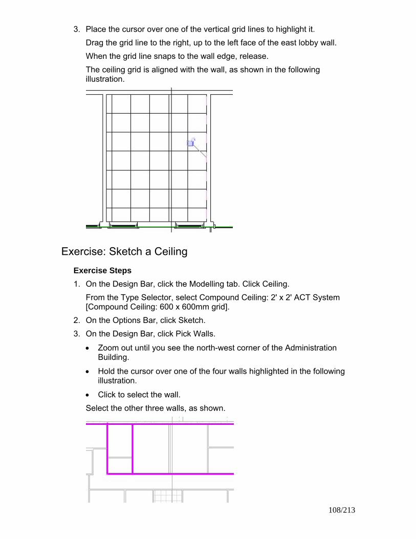
3. Place the cursor over one of the vertical grid lines to highlight it. Drag the grid line to the right, up to the left face of the east lobby wall. When the grid line snaps to the wall edge, release. The ceiling grid is aligned with the wall, as shown in the following illustration.
Exercise: Sketch a Ceiling Exercise Steps 1. On the Design Bar, click the Modelling tab. Click Ceiling.
From the Type Selector, select Compound Ceiling: 2' x 2' ACT System [Compound Ceiling: 600 x 600mm grid].
2. On the Options Bar, click Sketch. 3. On the Design Bar, click Pick Walls.
• Zoom out until you see the north-west corner of the Administration Building.
• Hold the cursor over one of the four walls highlighted in the following illustration.
• Click to select the wall. Select the other three walls, as shown.
108/213

4. On the Toolbar, click Trim. On the Options bar, click Corner Trim.
Trim the walls to select the area for the new ceiling.
• Click the portion of one wall that you want to keep selected as a ceiling boundary.
• On a wall that corners the first wall, click the portion that you want to stay selected. The unwanted wall portion is no longer selected.
• Trim the other two wall sections that you no longer want selected until the selected area is as shown in the following illustration.
5. On the Design Bar, click Finish Sketch.
The new ceiling now looks like the following illustration.
6. Click File menu > Close to exit the project. Do not save any changes.
109/213

Exercise: Add a Flat Roof by Footprint You are designing a fire station. You need to add roofs to the Administration Building, the Apparatus Bay, and the corridor that connects both buildings. Your design calls for a flat roof and two types of sloped roofs.
Exercise Steps 1. Open i_Firestation_Roofs.rvt (imperial) or m_Firestation_Roofs.rvt.
(metric).
Change the view to Floor Plans: Main Roof. Zoom in around the Apparatus Bay.
2. On the Design Bar, Basics tab, click Roof > Roof by Footprint. Click Pick
Walls. 3. On the Options Bar, clear Defines Slope.
In the Overhang field, enter 0' 0" (0mm). Select Extend to Wall Core.
110/213

4. Place your cursor over one of the exterior walls of the Apparatus Bay. Press TAB to highlight all of the exterior walls. Click to select all four walls.
If necessary, click the control flip arrows to position the sketched lines on the outer edge of the core boundary.
5. On the Design Bar, click Roof Properties. From the Type Selector, select Steel - Truss - Insulation on Metal Deck - EPDM to change the roof type. Click OK.
111/213
6. On the Design Bar, click Finish Roof. Click Yes to cut and join geometry.
7. Change the view to Sections (Wall Section):
Section 2. The new roof is displayed as shown in the illustration below.

Exercise: Add a Sloped Roof by Footprint Exercise Steps 1. Change the view to Floor Plan: Lower Roof. Zoom in on the Administration
Building. 2. On the Design Bar, click Roof > Roof by Footprint. 3. On the Options bar, click Defines Slope.
In Overhang, enter 2' 0" (600mm). Clear Extend Into Wall.
4. On the Design Bar, click Pick Walls.
Select only the exterior walls as shown in the following illustration to sketch a roof. Do not select all of the walls.
5. On the toolbar, click Trim/Extend On the Options Bar, click Corner Trim.
Extend the roof footprint lines in the upper-left and the lower-right corners of the building:
• Click the first roof footprint line you want to extend.
• Click the second roof footprint line you want to extend. Trim the roof footprint lines on either side of the front-entry lobby:
• Click the part of the first roof footprint line you want to keep.
• Click the part of second roof footprint line you want to keep.
The unwanted portion of the roof footprint line is no longer highlighted.
112/213

The completed footprint of your roof is displayed as shown by the highlighted lines in the following illustration.
6. On the Design Bar, click Roof Properties.
In the Type Selector, select Wood Rafter 8" - Asphalt Shingle - Insulated (m_Wood Rafter 184mm - Asphalt Shingle - Insulated). Click OK.
7. Click Finish Roof. The exterior walls are highlighted. Click Yes.
8. Change the view to 3D Views: {3D} to see the new roof.
Your roof is displayed as shown in the following illustration.
Exercise: Edit Roof Properties Exercise Steps
1. In a 3D view, select the Administration Building roof. 2. On the Options Bar, click Edit. 3. Change the view to Floor Plans: Lower Roof.
113/213

4. Select the slope-defining line at the entrance of the building as indicated in the following illustration.
On the Options Bar, clear Defines Slope Click on a blank area of the view window to clear the selection.
5. Select all the remaining slope-defining lines of the roof. On the Options Bar, click Roof Properties. In the Properties dialog box, change the Rise/12" (m_Slope Angle) to 6" (20°). Click OK.
6. On the Design Bar, click Finish Roof.
Change the view to 3D Views: {3D}. Your roof is displayed as shown in the following illustration.
114/213

Exercise: Add an Extruded Roof Exercise Steps 1. Change the view to Floor Plans: Lower Roof. 2. On the Design bar, Basics tab, click Ref Plane.
Zoom in on the space between the two buildings. Sketch a reference plane horizontally across the corridor between the Administration Building and Apparatus Bay as shown in the following illustration.
3. On the Design Bar, click Roof > Roof by Extrusion. 4. In the Work Plane dialog box, click Pick a Plane.
Click OK. Select the reference plane created in step 2.
5. In the Go To View dialog box, select Section: Section 3. Click Open View. The drawing is displayed in your view as shown in the following illustration.
115/213

6. In the Roof Reference Level and Offset dialog box, Level, select Lower Roof. In Offset, enter 0' 0" (0mm).
Click OK.
7. On the Design Bar, click Lines. Sketch the top edge of the roof as shown in the follwing illustration.
Using the reference planes as guides to draw the roof, snap the lines to the reference plane intersections. On the Design Bar, click Modify to finish sketching.
8. On the Design Bar, Sketch tab, click Properties. Select Wood Rafter 8" - Asphalt Shingle - Insulated (m_ Wood Rafter 184mm - Asphalt Shingle - Insulated) to change the roof type. Click OK.
9. On the Design Bar, click Finish Sketch. The drawing is displayed in your view like the one shown in the following illustration.
10. Change the view to 3D Views: {3D} to see the new roof.
116/213

11. On the toolbar, click Join Roofs. Select the edge of the extruded roof.
NOTE: With the Metric project file, if the extruded roof does not properly join to the roof and walls of the Administration Building in the next step, select the edge of the northern-sloping roof section, rather than the southern-sloping section as shown in the above illustration.
12. On the toolbar, select Dynamically Modify View. Rotate the model to show the north wall of the Administration Building. Select the upper north wall of the Administration Building. Close the Dynamic View dialog box. The extruded roof is joined to the main roof and the north wall as shown in the following illustration.
117/213
13. The extruded roof penetrates the entire length of the Apparatus Bay. On the toolbar, click Join Roofs. Select the edge of the extruded roof that is extending from the north end of the Apparatus Bay.
On the toolbar, select Dynamically Modify View.

Rotate the model to show the south wall of the Apparatus Bay. Select the south wall. The extruded roof is now joined correctly as shown in the following illustration.
Exercise: Attach Walls to Roof Exercise Steps 1. Change the view to Section: Section 3. 2. Press CTRL.
Select the two exterior walls. Release CTRL. On the Options Bar, click Attach. In Attach Wall, click Top.
3. Select the extruded roof. The drawing is displayed in your view as shown in the following illustration.
4. Click File menu > Close to exit the project. Do not save any changes.
118/213

Exercise: Creating L-shaped Stairs You are designing a fire station and want to add stairs from one floor to another.
Exercise Steps 1. Open i_Firestation_Stairs.rvt (imperial) or m_Firestation_Stairs.rvt
(metric). 2. In the Project Browser, change the view to Floor Plans: Main Floor.
Zoom in to the upper-right corner of the Apparatus Bay.
3. Click File menu > View > Visibility/Graphics. 4. In the Visibility/Graphics Overrides dialog box, Model Categories tab, in
the Visibility column, expand Floors. Clear the Surface Pattern check box.
5. On the Annotation Categories tab, clear the Grids check box.
Click OK.
6. On the Design Bar, Modelling tab, click Stairs.
119/213

7. On the Design Bar, click Run. On the Options Bar, the Line tool is selected by default. Start at the intersection of the lower horizontal reference plane (green dashed line) and the right vertical reference plane. Draw a line vertically upward using the vertical reference plane as a guide. Snap the first run to the intersection of the next horizontal reference plane. The length is 2' 9" [1650mm], as shown in the following illustration.
8. Use the third horizontal reference plane as a guide to sketch the next
horizontal run. The end of the run intersects with the wall face.
The drawing looks like the following illustration.
9. On the Design Bar, click Finish Sketch.
120/213

10. On the Design Bar, View tab, click Elevation. The elevation symbol is displayed at the cursor. Move the cursor until the triangle of the elevation symbol points toward the wall and stairs, as shown in the following illustration. Click to place the symbol.
11. On the Design Bar, click Modify.
Double-click the triangle on the elevation symbol to open the elevation view. The drawing looks like the following illustration.
Exercise: Adding Railings to Stairs and Landing Exercise Steps 1. In the Project Browser, change the view to Floor Plans: Main Floor.
On the Design Bar, click Modify. In the view window, select one of the stair railings. CTRL+ click to select the second railing.
2. From the Type Selector, select Railing Handrail - Pipe to change the railing type.
3. In the Project Browser, change the view to Floor Plans: Lower Roof. 4. On the Design Bar, Modelling Tab, click Railing. 5. Click Railing Properties.
In the Elements Properties dialog box, select Handrail - Pipe from the Type list. Click OK.
121/213

6. On the Design Bar, click Lines. On the Options Bar, click the Line tool. Select the Chain option.
7. Sketch along two edges of the floor, as shown in the following illustration.
8. On the Design Bar, click Finish Sketch. 9. In the Project Browser, expand Views (All): Elevations (1/2" Square).
Double-click Elevation 1-a. The view looks like the following illustration.
10. Click File menu > Close to exit the project. Do not save any changes.
122/213

123/213

Chapter 8: Using Building Components Chapter Exercises
• Exercise: Adding Components
• Exercise: Creating a New Door by Modifying an Existing Type
Exercise: Adding Toilets and Sinks to the Toilet Rooms In this exercise you add new components to the model and move them.
Exercise Steps 1. Open i_Firestation_Components.rvt (imperial) or
m_Firestation_Components.rvt (metric). If the active view is not Floor Plans: Ground Floor, switch to that view.
2. Zoom in around the upper-left corner of the Administration Building where the men's and women's public toilets are located.
Notice that the toilet partitions, grab bars, and a urinal screen already have been placed in the rooms.
3. On the Design Bar, Basics tab, click Component. From the Type Selector, select Toilet-Commercial-Wall-3D:19" Seat Height [M_ Toilet-Commercial-Wall-3D:480mm Seat Height].
4. Move the cursor to the plumbing chase wall, which separates the two rooms. Move the cursor toward the upper stall. The outline of the toilet is displayed. Click to place the toilet. (The exact location does not matter.)
5. On the Design bar, Basics tab, click Modify.
124/213

Select the toilet you just placed. 6. Place the cursor over the blue square grip of the temporary dimensions to
the left of the toilet. Drag the grip to the interior face of the concrete wall. The dimension reference is updated as indicated in the following illustration.
7. Click the blue dimension value between the wall face and the centerline of
the toilet. Change the distance to 1' 6" [450 mm].
8. On the Design Bar, click Component
From the Type Selector, select Toilet-Commercial-Wall-3D: 15" Seat Height [M_ Toilet-Commercial-Wall-3D: 380mm Seat Height].
9. Place a toilet in the stall to the right of the first toilet as shown in the following illustration.
125/213

10. On the Design bar, Basics tab; click Modify. Select the toilet you just placed. Place the cursor over the blue square of the temporary dimensions to the left of the toilet. Drag the control to the interior face of the toilet partition. Click the dimension value between the wall face and the centerline of the toilet. Change the distance to 1' 6" [450 mm] as indicated in the following illustration.
11. Add a Toilet-Commercial-Wall-3D: 19" Seat Height [M_Toilet-Commercial-
Wall-3D: 480mm Seat Height] to the men's public toilet room using the following illustration as a reference. Position the toilet 1' 6" [450 mm] from the interior face of the west wall.
12. Use the techniques you just learned to
add a Urinal-Wall-3D [M_Urinal_3D] as shown in the following illustration. Position the urinal 1' 6" [450 mm] from the left urinal screen.
126/213

13. On the Design Bar, Basics tab, click Component. From the Type Selector, select Sink-Wall-Barrier Free-3D: 22" x 27" [m-Sink-Wall-Barrier Free-3D: 560 x 685mm]. Add a sink to each toilet room. Position each sink as shown in the following illustration.
Exercise: Duplicating the Layout In this exercise, you copy a group of components, add them to another floor, and make adjustments to fit the components to the new room.
Exercise Steps 1. On the Design Bar, click Modify.
In the Project Browser, click to expand the Families branch. Click to expand the Specialty Equipment branch
2. Click to expand the Grab Bar-3D family. Right-click the Grab Bar-3D [m-Grab Bar-3D]. Click Select All Instances.
127/213

3. On the Design Bar, click Modify. 4. Move the cursor to the upper-left corner of the toilet rooms. Using the
following illustration as a reference, drag a selection box around the two toilet rooms.
5. On the Options Bar, click Filter. In the Filter dialog box, notice that all the objects in the selection box are listed by category.
NOTE: Your list may vary depending on the selection box that you drew.
128/213
6. Clear the Door Tags check box. If the Other check box is displayed, clear it as well. Click OK to remove the cleared check boxes from the selection set.

7. Using the following illustration as a guide, press SHIFT and select any walls that are not supposed to be selected. .
The only objects in the selection set are the plumbing fixtures, toilet partitions, grab bars, toilet room entry doors, and the four interior walls shown in the following illustration.
8. On the Edit menu, click Copy to
Clipboard. 9. In the Project Browser, open the
view Floor Plans: Main Floor. On the Edit menu, click Paste Aligned > Current View. The selected objects are copied to the main floor.
NOTE: You need to modify some items after copying.
129/213

10. Select the larger toilet partition in the upper toilet room. From the Type Selector, select Toilet Stall-Accessible-side2-3D:60" x 117" [Toilet Stall Accessible-Side2-3D: 1500mm x 2666mm]. The image looks like the following illustration.
11. On the Design Bar, click Modify.
In the upper toilet room, drag a selection box around the grab bars, toilet partitions, toilets, and sink.
12. On the Option Bar, click Move.
130/213
13. Set the base point for the move at the end of the grab bar as shown in the following illustration.

14. Move the cursor to the left over the interior face of the wall. When it is highlighted, click to complete the move. The selected objects are moved, as shown in the following illustration.
15. Click File menu > Close to exit the project. Do not save any changes.
Exercise: Creating a New Door by Modifying an Existing Type Your design needs a door type that is not supplied in the predefined types. In this exercise, you modify the dimensions and materials of an existing door type.
Exercise Steps 1. Open Imperial_Firestation.rvt (imperial) or Metric_Firestation.rvt (metric). 2. On the Design Bar, Basics tab, click Door.
From the Type Selector, select Single-Glass 1: 36" x 84" [Single-Glass 1: 0915 x 2134].
3. On the Options Bar, click Properties. 4. In the Element Properties dialog box, click Edit/New. 5. In the Type Properties dialog box, click Duplicate.
In the Name dialog box, enter 48" x 84" [1250 x 2134]. Click OK.
6. In the Type Properties dialog box, click Preview to display the preview window. From the View list, select Elevation: Exterior.
131/213

7. In the Width row, under Value, enter 4' 0" [1250mm].
8. Enter the following values for these type parameters
Rail Width - Base: 1' 6" [500mm]. Stile Width - Hinge: 1' 0" [300mm]. Stile Width - Latch: 1' 0" [300mm].
9. Click Apply to see the changes in the preview window.
10. Click the Value column of the Door Material type parameter. Click the
down arrow that is displayed in the column.
132/213

11. In the Materials dialog box, under Name, select Metal - Stainless.
Click OK.
12. Click the Value column of the Frame Material type parameter. Click the down arrow that is displayed.
13. In the Materials dialog box, under Name, select Metal - Chrome. Click OK.
NOTE: There is no parameter for the glass panel material. When the door type was created, this was not made a parameter that you can change.
14. Click OK. Click OK. 15. On the Design Bar, click Modify. 16. In the Project Browser, change the view to Floor Plans: Ground Floor.
Zoom in on the door in the center of the east wall. Click this door to select it.
17. From the Type Selector, select Single-Glass 1: 48" x 84" [Single-Glass 1:
1250 x 2134] to change the selected door to this type.
18. Click the X in the warning dialog box to close it.
133/213

19. Select the blue dimension number for the door.
Enter 2' 6" [800mm] as the new dimension. Press ENTER. The door moves down, away from the conflicting wall.
20. In the Project Browser, change the view to Elevations: East. Zoom in on the door. On the View Control Bar, change the Model Graphics Style to Shading with Edges.
The door looks like the following illustration.
21. Click File menu > Close to exit the project. Do not save any changes.
134/213

135/213

Chapter 9: Creating Schedules Chapter Exercises
• Exercise: Creating a Door Hardware Key Schedule and Door Schedule
• Exercise: Creating a Room Schedule
• Exercise: Controlling the Appearance of Schedules
Exercise: Create a Door Hardware Key Schedule You are designing a fire station and need to create schedules for the door and the door hardware that are in the building specifications.
Exercise Steps 1. Open i_Firestation_BasicSchedules.rvt (imperial) or
m_Firestation_BasicSchedules.rvt (metric). 2. On the Design Bar, View tab, click Schedule/Quantities.
In the New Schedule dialog box, under Category, select Doors.
Select Schedule Keys Under Name, enter Door Hardware Schedule Under Key Name, enter Door Hardware. Click OK.
136/213

3. In the Schedule Properties dialog box, Fields tab, click Add Parameter. 4. In the Parameter Properties dialog box,
under Name, enter Hardware Type Under Type, select Text. Click OK.
5. In the Schedule Properties dialog box, Fields tab, click Add Parameter,
again. In the Parameter Properties dialog box, under Name, enter Lockset. Under Type, select Text. Click OK.
6. Use the procedure in step 5 to add a text box named Hinges. 7. In the Schedule Properties dialog box, Fields tab, click Add Parameter.
In the Parameter Properties dialog box, under Name, enter Closer. Under Type, select Yes/No. Click OK.
8. Use the procedure in step 7 to add new Yes/No parameter boxes called Frame Silencer and Kickplate.
137/213

9. In the Schedule Properties dialog box, Formatting tab, under Fields, click Key Name.
Under Heading, enter Set. Click OK to create the schedule.
10. On the Options Bar, click New to add a new row to the schedule.
11. In the Hardware Type box in the row 1, enter Passage.
In the Lockset box, enter A-Series. In the Hinges box, enter 1 1/2 pr - BB 5 knuckle.
Clear the Closer and Kickplate check boxes. Select the Frame Silencer check box.
138/213

12. On the Options Bar, click New Use the procedure in step 11 to edit set 2 as shown.
13. Add four additional rows.
Edit the values for each new set as shown.
139/213

Exercise: Assign Door Hardware to Doors Exercise Steps 1. Change view to Floor Plans: Ground Floor. 2. CTRL+ select the rest room doors (#9 and #10).
On the Options Bar, click Properties.
NOTE: that the door hardware parameters you added in the previous part of this exercise are part of the door Instance Parameters list.
3. In the Instance Parameters list, under Value, click the Door Hardware box.
Select the predefined hardware set 5.
NOTE: that all the associated parameters are updated.
4. Click OK. 5. On the Ground Floor plan, select the egress door from the stairwell on the
left (#6). On the Options Bar, click Properties. From Hardware Type, select Egress.
140/213

6. For Door Hardware, under Value, select 3.
Click OK.
Create a Door Schedule and Add Values Exercise Steps 1. On the Design Bar, View tab, click Schedule/Quantities. 2. In the New Schedule dialog box, under Category, click Doors.
Under Name, accept the default schedule name (Door Schedule). Click Schedule Building Components.
Click OK.
141/213

3. In the Schedule Properties dialog box, Fields tab, from Available Fields, select Mark. Click Add.
4. Use the procedure in step 3 to add the following fields: Family and Type, Width, Height, Cost, Level, and Door Hardware as shown.
5. In the Schedule Properties dialog box, Sorting/Grouping tab, from Sort By,
select Mark.
6. Click OK to create the door schedule as shown.
7. In the Cost box for the Curtain Wall door (1A), enter 1895.
Press ENTER. The following message is displayed, indicating that all doors of this type will be updated.
Click OK.
142/213
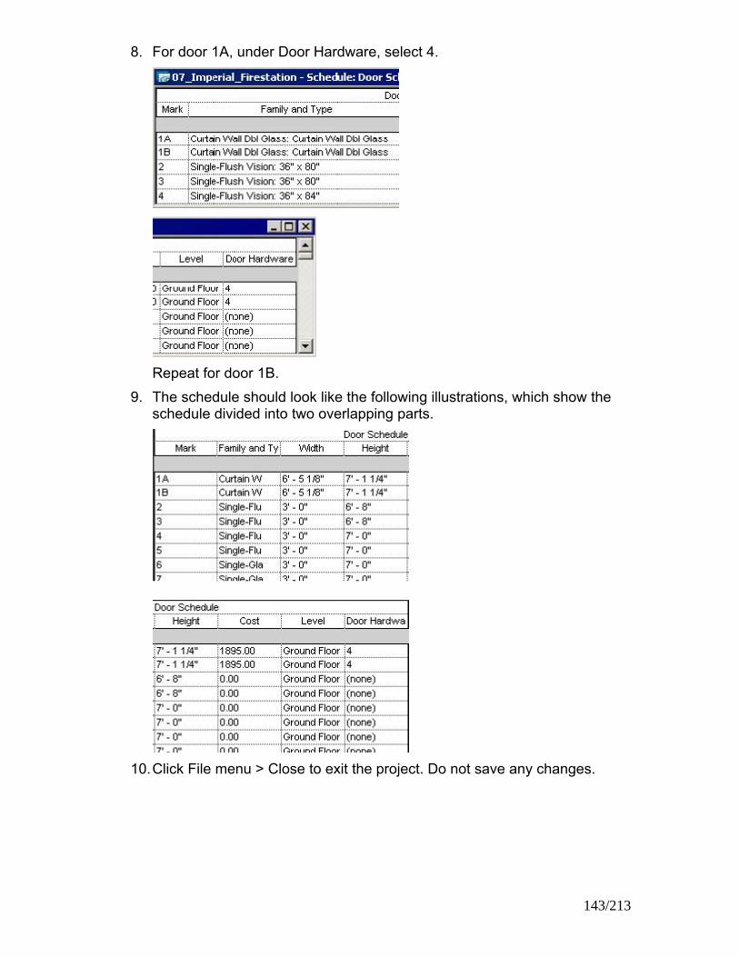
8. For door 1A, under Door Hardware, select 4.
Repeat for door 1B.
9. The schedule should look like the following illustrations, which show the schedule divided into two overlapping parts.
10. Click File menu > Close to exit the project. Do not save any changes.
143/213

Exercise: Create a Room Schedule and Define Rooms You are designing a fire station and need to create schedules for the rooms that are in the building specifications.
Exercise Steps 1. Open i_Firestation_RoomSchedules.rvt (imperial) or
m_Firestation_RoomSchedules.rvt (metric). 2. On the Design Bar, View tab, click Schedule/Quantities.
In the New Schedule dialog box, under Category, select Rooms.
By default, the name of the new schedule is Room Schedule, and Schedule Building Components is selected.
Click OK. 3. In the Schedule Properties
dialog box, Fields tab, under Available Fields, select Number. Click Add. Use the same procedure to add these fields: Name, Level, Area, and Comments.
144/213

4. Click the Sorting/Grouping tab. From the Sort By list, select Number.
5. Click the Formatting tab.
From the Fields list, click Area. Under Alignment, select Right. Under Field Formatting, select the Calculate Totals check box.
6. Click OK.
A room schedule is created as shown. Because no rooms are selected, the schedule is empty.
7. In the Project Brower, expand Schedules/Quantities. Click Room
Schedule. In the view window, click the room schedule. On the Options Bar, click Rows: New.
145/213

A new row is added to the schedule as shown.
8. In the Name field, click Room. Enter Lobby.
In the Number field, click 1. Enter 101. The schedule looks like the following figure.
9. On the Options Bar, click New five times
Five new rows for five rooms are added. The schedule looks like the following figure.
10. Edit the names of the rooms, as shown.
Exercise: Assign Room Tags to Rooms Exercise Steps 1. In the Project Browser, expand Views (All):
Floor Plans. Double-click Ground Floor. 2. On the Design Bar, Drafting tab, click
Room Tag. 3. On the Options Bar, from Room, select 101 Lobby.
146/213

4. Move the cursor to the lobby area of the Administration Building. Click to place the tag.
5. Follow the procedure in steps 3 and 4 to place tags in five other rooms, as shown in the following figure.
6. On the Design Bar, click Modify.
In the View Window, select the room tag Lobby. On the Options Bar, click Properties.
7. In the Element Properties dialog box, in Comments, enter Public Entrance. Click OK.
8. In the Project Browser, expand Views (All): Schedules/Quantities. Double-click Room Schedule. The level, area information, and comment have been added to the schedule, as shown.
9. In the Project Browser, change the active view back to Floor Plans:
Ground Floor. On the Design Bar, Drafting tab, click Room Tag On the Options Bar, click the Room list. The only option available is Auto.
10. Move the cursor to the toilet room closest to the stairs. Click to place a tag.
147/213

11. On the Design Bar, click Modify. Select the new tag (107). Click on the name. Change it to Men's Toilet Room.
12. In the Project Browser, change the active view back to Floor Plans: Main
Floor. On the Design Bar, Drafting tab, click Room Tag.
13. Move the cursor to the room adjacent to the toilet rooms. Click to place a tag.
14. On the Design Bar, click Modify.
Click on the name. Change it to Sleeping Quarters. Click on the number. Change it to 201.
148/213

15. On the Design Bar, click Room Tag. Place a tag in the sleeping quarters to the right of room 201.
Click on the name. Change it to Sleeping Quarters.
16. Select the tag for Room 202.
On the toolbar, click Copy. On the Options Bar, select Copy. Select Multiple.
17. Click on the tag for Room 202.
Move the curser to the adjacent room. Click to place a new tag. Repeat in the next room.
18. Change the name of the rooms. Your view looks like the following illustration.
19. Click File menu > Close to exit the project. Do not save any changes.
149/213

Exercise: Controlling the Appearance of Schedules A schedule already exists for all the doors in this project. In this exercise you create a schedule of only the doors on the ground floor. You also change how the schedule looks when you add it to a drawing sheet.
Exercise Steps 1. Open i_Schedule_Appearance.rvt (imperial) or
m_Schedule_Appearance.rvt (metric). 2. In the Project Browser, double-click Door Schedule. In the schedule view
window, right-click Door Schedule. Click View Properties. 3. To sort the schedule:
• In the Schedule Properties dialog box, in the Sorting/Grouping row, click Edit.
• From the Sort By list, select Level. Select Header.
• From the Then By list, select Mark. Clear Header.
• In the lower-left corner of the tab, select Grand Totals.
4. To format the schedule:
• In the Schedule Properties dialog box, from the Fields list, select Cost. From the Alignment list, select Right. Select Calculate Totals.
• From the Fields list, select Level. Select Hidden Field to hide the Level field in the schedule,
• From the Fields list, select Family and Type. In the Heading field, change the value to Door Type. Click OK.
• Click OK.
150/213

The schedule looks like the following figure.
5. To make a copy of the schedule:
• In the Project Browser, right-click the name of the schedule.Click Duplicate.
• In the Project Browser, right-click Copy of Door Schedule. Click Rename. Enter Ground Floor Door Schedule.
• Click OK. 6. To filter the duplicate schedule:
• In the Project Browser, double-click Ground Floor Door Schedule to make it the active view.
• In the Project Browser, right-click Ground Floor Door Schedule. Click Properties.
• In the Sorting/Grouping row in the Schedule Properties dialog box, click Edit.
• From the Sort By list, select (none).
• Click the Filter tab. From the Filter By list, select Level. From the list to the right of Filter By, select Equals. From the list below Filter By,select Ground Floor as the level.
• Click OK twice.
151/213

7. To create a new drawing sheet:
• In the Project Browser, right-click Sheets. Click New Sheet.
• In the Select a Titleblock dialog box, click OK.
• In the Project Browser, highlight Ground Floor Door Schedule. Drag the Ground Floor Door schedule over the view window. Release the mouse button to see the schedule.
• Click to position the schedule. Zoom in on the schedule on the sheet.
8. To change the schedule's print format:
• In the Project Browser, right-click Ground Floor Door Schedule. Click Properties.
• In the Schedule Properties dialog box, in the Appearance row, click Edit.
• Change the size of the Header Text from 1/8 inch to 3/16 inch [3.175 mm to 5 mm]. Select Bold.
• Clear Blank Row Before Data.
• Click the Formatting tab. From the Fields list, select Mark. Select the Hidden Field check box.
• Click OK twice.
152/213

9. To resize the schedule columns on the sheet:
• Click the schedule on the sheet. Drag the triangular column grips to resize the column so that the text fits.
• Click the sheet outside the schedule to clear the selection of the schedule.
10. The schedule on the sheet looks like the following figure.
11. Click File menu > Close to close the project. Do not save changes.
153/213

Chapter 10: Drafting and Detailing Chapter Exercises
• Exercise: Creating a Callout View
• Exercise: Detailing
• Exercise: Creating a Drafting View
Exercise: Creating a Callout View You are designing a fire station and need to create callout views to show more detail for certain areas of the plans.
Exercise Steps 1. Open i_Firestation_Callouts.rvt (imperial) or m_Firestation_Callouts.rvt
(metric). 2. In the Project Browser, expand Views (All): Sections (Building Section).
Double-click Section 1. On the Design Bar, View tab, click Callout.
3. From the Type Selector, select Detail View: Detail.
From the Scale list, select 3/4" = 1'-0" [1:20].
4. In the area where the north
wall connects to the roof, click to place the upper-left corner of the callout. Drag to the corner diagonally down and right. Click to place the lower-right corner of the callout, as shown in the following illustration.
154/213

5. Click the border of the callout bubble to select the callout, as shown in the following illustration.
6. Drag the blue-dot handles to edit the size of the callout.
Click the dot adjacent to the callout head.
Drag the callout head up, as shown in following illustration.
7. Move the cursor over the dot at the middle of the leader. Click to adjust
the leader position, as shown in the following illustration.
8. Right-click the callout head.
Click Go to View to open the callout view. The callout view looks like the following illustration.
9. Click File menu > Close to exit the project. Do not save any changes.
155/213

Exercise: Create a Detail View In this exercise, you create a detail view showing the construction details of the Apparatus Bay wall.
Exercise Steps 1. Open i_Firestation_Detailing.rvt (imperial) or m_Firestation_Detailing.rvt
(metric). 2. In the Project Browser, expand Views (All): Floor Plans. Double-click Floor
Plans: Main Roof.
3. Double-click the section head on
the left wall of the Apparatus Bay to open section 2.
4. Double-click the callout bubble at the top of the section view to open the callout view.
156/213

5. Select the crop boundary. Drag the shape handles to modify the crop boundaries of the view so that it includes the entire parapet as shown.
6. In the Project Browser, right-click the view named Callout of Section 2.
Click Rename. Rename the view Parapet Detail. Click OK.
7. On the View menu, click View Properties. 8. In the Element Properties dialog box, under Instance Parameters, from
Far Clip Offset , select Independent. In the Far Clip Settings value box, enter 2' 0" [600mm]. Click OK.
9. Select the roof. On the Option Bar, Type Selector, select Concrete - Insulated. The roof is displayed as shown.
157/213
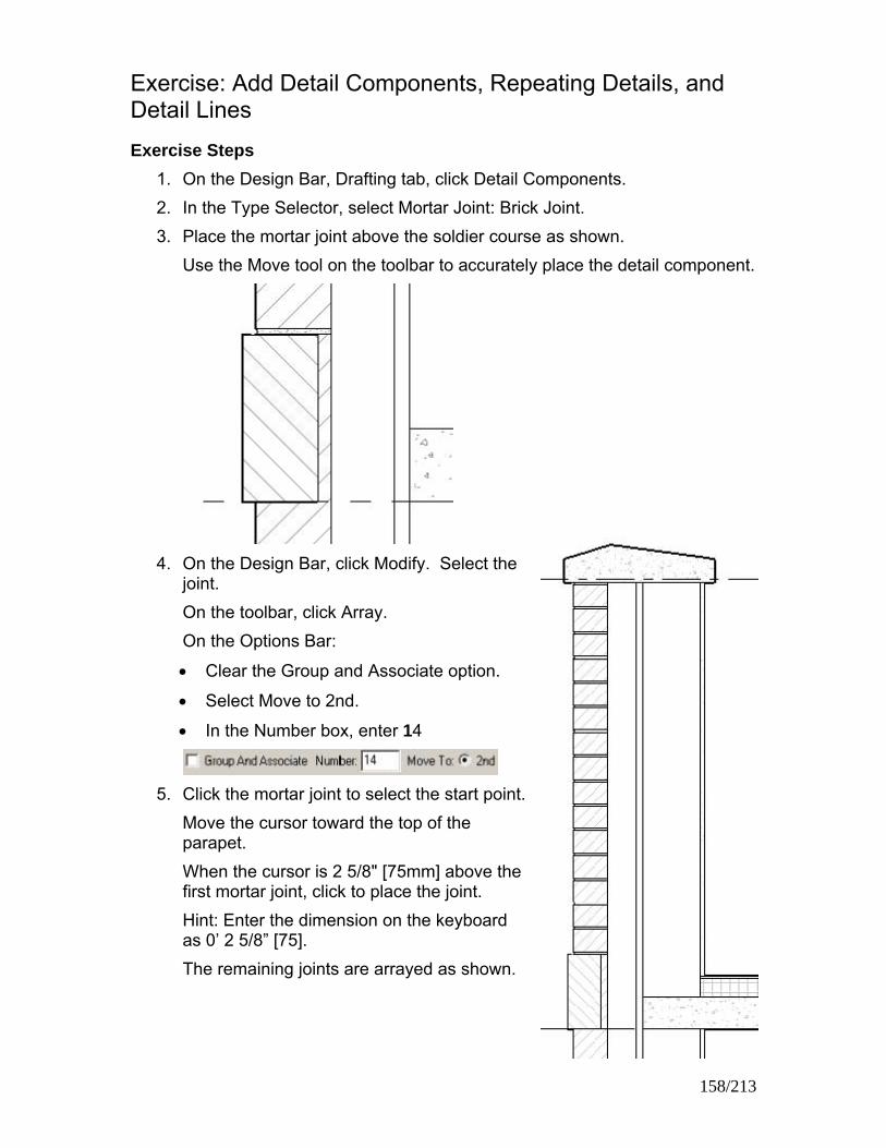
Exercise: Add Detail Components, Repeating Details, and Detail Lines Exercise Steps
1. On the Design Bar, Drafting tab, click Detail Components. 2. In the Type Selector, select Mortar Joint: Brick Joint. 3. Place the mortar joint above the soldier course as shown.
Use the Move tool on the toolbar to accurately place the detail component.
4. On the Design Bar, click Modify. Select the
joint. On the toolbar, click Array. On the Options Bar:
• Clear the Group and Associate option.
• Select Move to 2nd.
• In the Number box, enter 14
5. Click the mortar joint to select the start point.
Move the cursor toward the top of the parapet. When the cursor is 2 5/8" [75mm] above the first mortar joint, click to place the joint. Hint: Enter the dimension on the keyboard as 0’ 2 5/8” [75]. The remaining joints are arrayed as shown.
158/213

6. Add another mortar joint below the soldier course, using the procedures in steps 2 through 5. Array the mortar joint seven times. Use the following illustration as a reference.
7. Zoom in to the wall to the roof join. 8. On the Design Bar, select Detail component.
From the Type Selector, select Cant Strip: 3' 3" [Cant Strip: 75mm x 75mm].
9. Place the cant strip as shown.
10. On the toolbar, click Thin Lines.
11. On the Design Bar, click Detail Lines.
From the Type Selector, select Medium Lines. On the Options Bar, select Chain.
159/213

Enter an offset of 0' 1/4" [6mm]. Sketch the two lines shown in the following illustration, tracing the cant strip and the top of the roof.
NOTE: Sketch left to right.
12. Click File menu > Close to exit the project. Do not save any changes.
The finished detail looks like the following illustration.
160/213
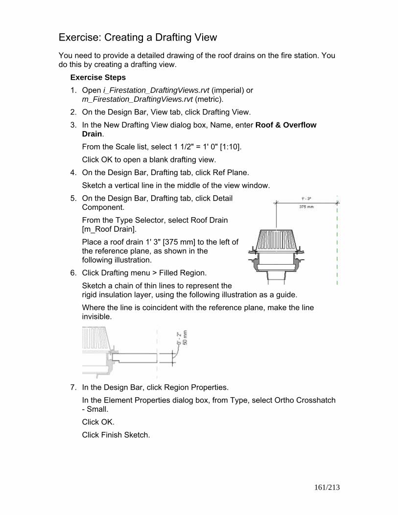
Exercise: Creating a Drafting View You need to provide a detailed drawing of the roof drains on the fire station. You do this by creating a drafting view.
Exercise Steps 1. Open i_Firestation_DraftingViews.rvt (imperial) or
m_Firestation_DraftingViews.rvt (metric). 2. On the Design Bar, View tab, click Drafting View. 3. In the New Drafting View dialog box, Name, enter Roof & Overflow
Drain. From the Scale list, select 1 1/2" = 1' 0" [1:10]. Click OK to open a blank drafting view.
4. On the Design Bar, Drafting tab, click Ref Plane. Sketch a vertical line in the middle of the view window.
5. On the Design Bar, Drafting tab, click Detail Component. From the Type Selector, select Roof Drain [m_Roof Drain]. Place a roof drain 1' 3" [375 mm] to the left of the reference plane, as shown in the following illustration.
6. Click Drafting menu > Filled Region. Sketch a chain of thin lines to represent the rigid insulation layer, using the following illustration as a guide. Where the line is coincident with the reference plane, make the line invisible.
7. In the Design Bar, click Region Properties.
In the Element Properties dialog box, from Type, select Ortho Crosshatch - Small. Click OK. Click Finish Sketch.
161/213

8. Drafting Menu > Filled Region. Sketch a chain of thin lines to represent a roof membrane layer with a thickness of 1/4" [7 mm], as shown in the following illustration. Where the line is coincident with the reference plane, make the line invisible.
Click Region Properties. In the Element Properties dialog box, from the Type list, select Sand - Very Dense. Click OK. Click Finish Sketch.
9. In the Design Bar, click Detail Lines. From the Type Selector, select Thin Lines. Draw the roofing membrane, as shown. Extend the membrane all the way to the reference plane.
10. Zoom out.
Click Modify. Drag a crossing selection window from right to left to select the detail lines and filled regions that you just created.
11. On the Toolbar, click Mirror. On the Options Bar, select the Copy check box. Click the centerline of the roof drain as a mirror axis.
162/213

12. Click Detail Component. From the Type Selector, select Break Line [m_Break Line]. Place a break line, as shown in the following illustration. Press SPACE BAR to rotate the break line to position it correctly.
13. Drag a crossing selection window from right to left to select all elements
except the reference plane. On the Toolbar, click Mirror. On the Options Bar, select the Copy check box. Click the reference plane of the roof drain as the mirror axis.
14. Select the drain on the right.
Right-click. Click Properties. In the Element Properties dialog box, under Instant Parameters, enter 2" [50 mm] for Ring Height. Click OK. Only the instance of the drain on the right is affected, as shown.
15. Zoom in to the overflow drain on the right.
Dimension the overflow drain, using the following illustration as a guide. Select the blue text grab handle and move the dimension upward. Notice that a curved leader is displayed.
163/213
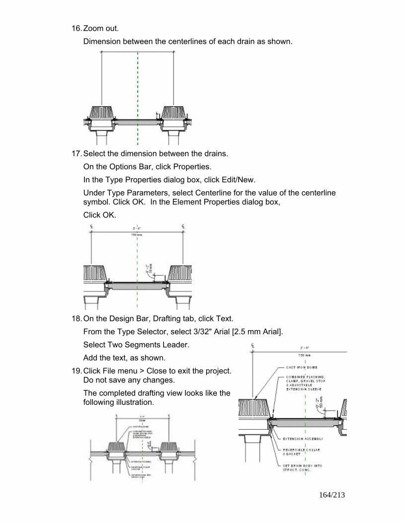
16. Zoom out. Dimension between the centerlines of each drain as shown.
17. Select the dimension between the drains.
On the Options Bar, click Properties. In the Type Properties dialog box, click Edit/New. Under Type Parameters, select Centerline for the value of the centerline symbol. Click OK. In the Element Properties dialog box, Click OK.
18. On the Design Bar, Drafting tab, click Text.
From the Type Selector, select 3/32" Arial [2.5 mm Arial]. Select Two Segments Leader. Add the text, as shown.
19. Click File menu > Close to exit the project. Do not save any changes. The completed drafting view looks like the following illustration.
164/213

165/213

Chapter 11: Presenting the Building Model Chapter Exercises
• Exercise: Creating a Section View
• Exercise: Creating a 3D Perspective View
• Exercise: Creating a Rendering
• Exercise: Drawing Sheets
• Exercise: Adding and Updating Titleblocks
• Exercise: Controlling Object Visibility
Exercise Creating a Section View You need to create section views of the building to show the interior layout of the fire station.
Exercise Steps 1. Open Imperial_Firestation.rvt (imperial) or Metric_Firestation.rvt (metric). 2. In the Project Browser, expand Views (All): Floor Plans. Double-click
Ground Floor. On the Design Bar, View tab, click Section.
3. Position the cursor on the south side of the building, as shown in the following illustration. Click once to place the section head. Move the cursor to the north side of the building. Click once to place the section tail. The new section view is named Section 4.
4. In the Project Browser, expand Sections (Building Section) [metric: Sections (12mmHead)]. Double-click Section 4. The view is similar to the following illustration.
166/213
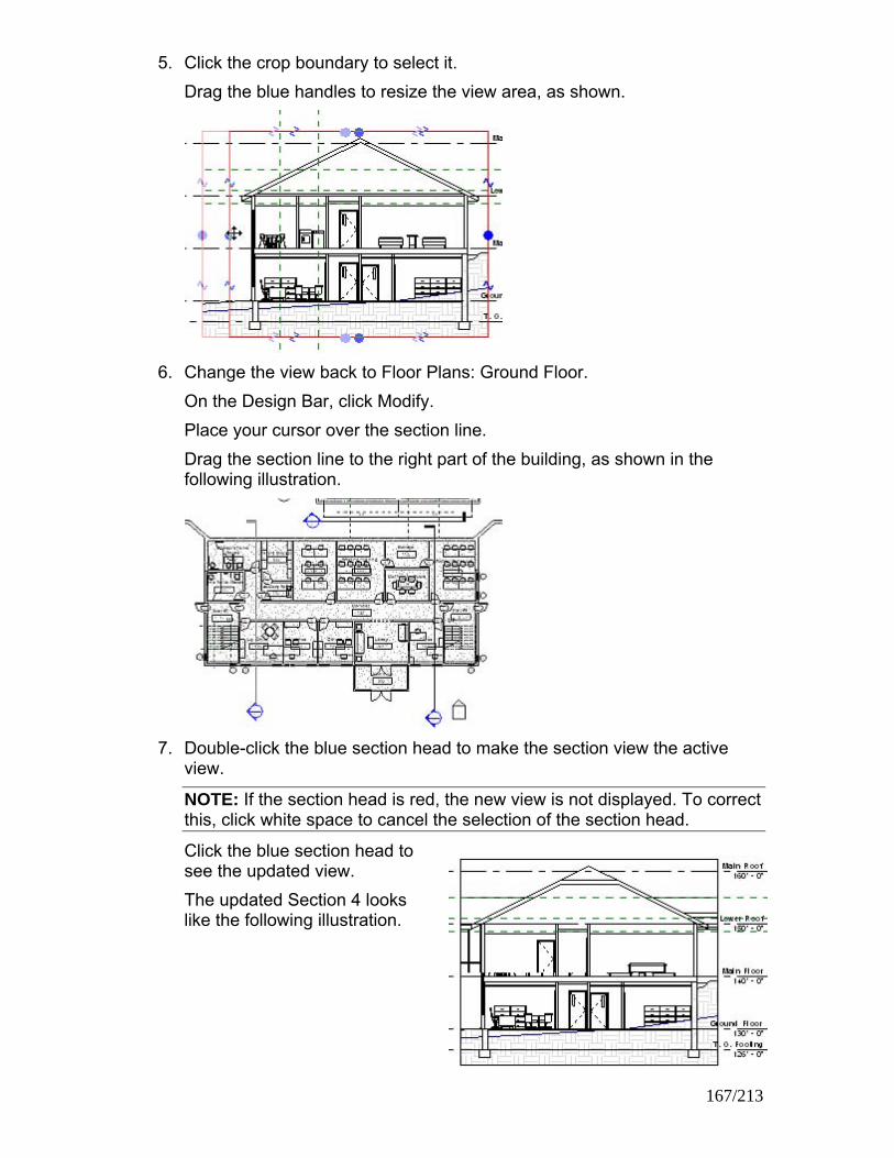
5. Click the crop boundary to select it. Drag the blue handles to resize the view area, as shown.
6. Change the view back to Floor Plans: Ground Floor.
On the Design Bar, click Modify. Place your cursor over the section line. Drag the section line to the right part of the building, as shown in the following illustration.
7. Double-click the blue section head to make the section view the active
view.
NOTE: If the section head is red, the new view is not displayed. To correct this, click white space to cancel the selection of the section head.
Click the blue section head to see the updated view. The updated Section 4 looks like the following illustration.
167/213

8. Change the view back to Floor Plans: Ground Floor. On the Design Bar, click Modify. Select the section line. Blue flip control arrows are displayed close to the section head. Click the flip control arrows.
The section symbol points in the opposite direction.
9. Double-click the section head to make the section view the active view. The updated Section 4 looks like the following illustration.
10. Change the view back to Floor Plans: Ground Floor. On the Design Bar, click Modify. Select the section line.
11. On the Options Bar, click Split Segment.
The cursor changes to show an arrow and a knife. 12. Move the cursor to the point where the section line crosses the north wall
of the corridor, as shown.
168/213

13. Click to split the section line. Drag the lower part of the section line to the right, over the stairs.
Click to place the split segment of the section line.
14. On the Design Bar, click Modify. Double-click the section head to make the section view the active view. The updated Section 4 looks like the following illustration.
15. Click File menu > Close to exit the project. Do not save any changes.
Exercise: Creating a 3D Perspective View You need to create a 3D perspective view of the model to show your client an exterior view of the completed fire station.
Exercise Steps 1. Open Imperial_Firestation.rvt (imperial) or Metric_Firestation.rvt (metric).
169/213
2. Change the view to Floor Plans: Ground Floor. 3. On the Design Bar, View tab, click
Camera. Position the cursor below the south wall of the fire station, as shown in the following illustration. Click to place the camera. Move the cursor to where you want the camera target point. Click to place the target point. A new 3D perspective view is created with the default name of 3D View 1.

4. Change the view back to Floor Plans: Ground Floor. 5. In the Project Browser, right-click 3D Views: 3D View 1.
Click Show Camera. 6. Drag the camera to a new location, as shown in the following illustration.
Drag the target point to the new location.
7. Select the clip plane handle (blue dot on the plane farthest from the
camera). Move the clip plane away from the camera, as shown.
170/213

8. In the Project Browser, double-click 3D View 1. The view looks like the following illustration.
9. On the Options Bar, click the Size button.
In the Crop Region Size dialog box, enter 10" [250mm] for Width. Click OK. The width of the crop region changes, as shown in the following illustration.
10. Click File menu > Close to exit the project. Do not save any changes.
171/213

Exercise: Creating a Rendering You are preparing a presentation on your design for the fire station and need a realistic image depicting the building when it is completed. To do this, you make a rendering of a 3D view.
Exercise Steps 1. Open Imperial_Firestation.rvt (imperial) or Metric_Firestation.rvt (metric). 2. In the Project Browser, expand Views (All): 3D Views.
Double-click 3D View 1 3. In the Design Bar, Rendering
tab, click Settings. In the Scene Selection dialog box, enter Exterior Perspective for Name. Under Type, click Exterior Click OK.
4. In the Render Scene Settings dialog box, under Scene Settings, clear Use Sun and Shadow Settings From View. Click Sun.
5. In the Sun and Sky Settings
dialog box, Date and Time tab, from the Specify Solar Angles list, select By Date, Time and Place. Under Date, select 10 for Month. Select 5 for Day. Under Time, move the slide bar to approximately 2:30 pm. Press LEFT ARROW and RIGHT ARROW to accurately adjust the minutes.
172/213

6. In the Sun and Sky Settings dialog box, Place tab, move the cursor over the Cities list. Enter B. From the Cities list, select Boston, MA, USA.
7. In the Sun and Sky Settings dialog box, Settings tab, enter 0.20 for Cloudiness.
NOTE: Cloudiness ranges from 0 (no clouds) to 1.00 (most clouds).
Click OK. 8. In the Render Scene Settings dialog box, under Scene Settings, click
Environment. 9. In the Environment dialog box, under Background Color, click 2 Color
Gradient. Click the left color bar. In the Color Picker dialog box, select a medium-dark shade of blue. Click OK. Click the right color bar. In the Color Picker dialog box, select a light shade of blue. Click OK.
Under Advanced, select Clouds. 10. In the Environment dialog box, Clouds tab, select the Sheet Clouds check
box.
173/213

11. Under Scale group, for X, enter 3 to increase cloud size. For Y, enter 3.
12. For Density, enter 0.3 to increase the cloud density. Click OK.
13. In the Render Scene Settings dialog box, under Scene Settings, from the Plant Season list, select Autumn.
14. Click Lighting. In the Scene Lighting dialog box, Sun row, select On. Click OK.
15. In the Render Scene Settings dialog box, under Raytrace Settings, from
the Quality list, select Best. Click OK.
16. On the Design Bar, Rendering tab, click Image Size. 17. In the Image Size dialog box, enter 128 [60 dpcm] for Resolution.
Click OK.
174/213

18. Click the crop boundary of the Exterior Perspective view to select it. On the Options Bar, click Size. In the Crop Region Size dialog box, under Change, select Scale (Locked Proportions). Under Size, enter 6" [150mm]. Click OK.
19. On the Design Bar, Rendering tab, click Raytrace. On the Options Bar, click GO! It takes a few minutes to render the image.
20. Click File menu > Close to exit the project. Do not save any changes.
Exercise: Add a View to a Sheet In this exercise, you add a view to a drawing sheet. You place and manipulate multiple views on a sheet.
Exercise Steps 1. Open i_Firestation_Sheets.rvt (imperial) or m_Firestation_Sheets.rvt
(metric). 2. Click View menu > New > Sheet. 3. In the Select a Titleblock dialog box, select E1 30 x 42 Horizontal : E1 30 x
42 Horizontal [A1 metric]. Click OK.
The new sheet becomes the active view.
175/213

4. In the Project Browser, expand Views (All): Floor Plans. Right-click Ground Floor. Click Duplicate with Detailing to create a duplicate floor plan view.
5. In the Project Browser, right-click Floor Plans: Copy of Ground Floor.
Click Properties 6. In the Element Properties dialog box,
change the View Name to Administration Building Ground Floor. Select Crop Region. Click OK.
7. In the Project Browser, expand Views (All): Sheets. Double-click A101 – Unnamed to make that sheet the active view. Click View menu > New > Add View. In the Views dialog box, select Floor Plan: Administration Building Ground Floor.
Click Add View to Sheet.
176/213

8. Position the cursor in the sheet to display an outline of the view. Move the view, as shown.
Click once to place the view in the sheet.
9. Click the view in the view window. Click View menu > Activate View. Click View menu > View Properties. In the Element Properties dialog box, from the View Scale list, select 1/4" = 1'-0" [metric 1:50]. In the Element Properties dialog box, Visibility parameter row, click the Edit button. In the Visibility/Graphics Overrides dialog box, Annotation Categories tab, clear Elevations. Clear Grids. Click OK. Click OK.
10. Select the viewport border.
177/213

11. Drag the blue grips to bring the crop region in around only the Administration Building.
12. Click View menu > Deactivate View. 13. On the sheet, select the viewport. Drag the viewport into position on the
sheet, as shown.
14. Click a blank area of the view window to clear the selection.
Click the view title below the viewport.
Drag it up to just below the viewport.
15. On the Design Bar, View tab, click Modify. Position the cursor over the view title. Press TAB to isolate Viewport 1. Look at the status bar to confirm. Click the view title. Click the grip at the right of the view title. Drag the blue dots to adjust the view title length to fit the new view extents.
178/213
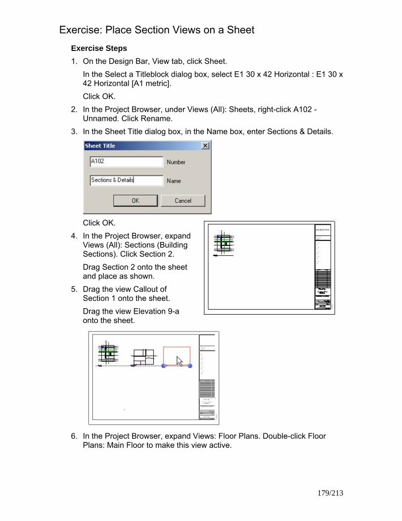
Exercise: Place Section Views on a Sheet Exercise Steps 1. On the Design Bar, View tab, click Sheet.
In the Select a Titleblock dialog box, select E1 30 x 42 Horizontal : E1 30 x 42 Horizontal [A1 metric]. Click OK.
2. In the Project Browser, under Views (All): Sheets, right-click A102 - Unnamed. Click Rename.
3. In the Sheet Title dialog box, in the Name box, enter Sections & Details.
Click OK.
4. In the Project Browser, expand Views (All): Sections (Building Sections). Click Section 2. Drag Section 2 onto the sheet and place as shown.
5. Drag the view Callout of Section 1 onto the sheet. Drag the view Elevation 9-a onto the sheet.
6. In the Project Browser, expand Views: Floor Plans. Double-click Floor
Plans: Main Floor to make this view active.
179/213

Zoom in on the upper-left corner of the upper building. The section head and elevation in the Apparatus Bay are updated to show the detail number and sheet number for these views.
7. Click File menu > Close to exit the project. Do not save any changes.
Exercise: Adding and Updating Titleblocks In this exercise, you add a titleblock to a drawing sheet and add project information to the titleblock.
Exercise Steps 1. Open i_Firestation_Titleblocks.rvt (imperial) or
m_Firestation_Titleblocks.rvt (metric). 2. In the Project Browser, expand Views (All): Sheets (All). Double-click
A101 Unnamed. 3. On the Design Bar, View tab, click Modify.
Zoom in on the lower-right corner of the sheet. Click the sheet to highlight parameters that you can edit.
180/213

4. Click the Sheet Name parameter. Change it from Unnamed to Ground Floor Plan. Change the following parameters:
• Enter River City for the owner.
• Enter Municipal Fire Station for the project name.
5. In the Project Browser, expand Sheets (All): double-click A102 Sections &
Details. Zoom in on the lower-right corner of the sheet. Notice that the sheet number has been incremented to A102. Notice that the Owner and Project Name parameters have been copied over, but the Sheet Name parameter has not been copied over.
181/213

6. Click View menu > New > Sheet. Select E1 30 x 42 Horizontal [A1 metric]. Click OK.
7. Zoom in on the lower-right corner of the new sheet. 8. Click Settings menu > Project Information. 9. In the Element Properties dialog box, notice that the client name is River
City and the project name is Municipal Fire Station.
10. In the Element Properties dialog box, enter new values as follows:
These are the values that you entered in the titleblock of sheet A101.
• In the Project Issue Date box, enter the current date.
• In the Project Status box, enter Client Review.
• In the Project Number box, enter 2005-67.
Click OK. Notice that the information in the titleblock has been updated.
182/213

11. Click the border of the titleblock to highlight it. On the Options Bar, click Properties. Change the value of the Drawn By parameter to your name.
Click OK.
12. In the view window, click the sheet to highlight parameters that you can edit. Click the sheet number to edit it. Enter A1.01 for the sheet number.
13. Enter Main Floor Plan for the sheet name. 14. Type ZF to zoom out. 15. In the Project Browser, highlight Views (All): Floor Plans: Main Floor. Drag
the floor plan onto the sheet. Click to place the view. 16. Zoom in on the lower-right corner of the sheet.
The scale has been updated to reflect the scale of the Main Floor Plan view.
17. In the view window, click the titleblock.
On the Options Bar, click Edit Family. In the Revit dialog box, click Yes to open the titleblock for editing.
183/213

18. In the Family Editor, zoom in on the upper-right corner of the titleblock. Click the upper consultant address block.
19. Highlight the text, and enter the following
information: Upright Steel Engineering 123 Main Street River City, IA 1-800-123-4567
20. Resize the text box by using the right blue grip.
Notice that you can also move or rotate the text box.
21. Highlight and delete the remaining three consultant address text blocks.
184/213

22. On the Design Bar, click Load into Projects. In the Reload Family dialog box, clear Override Parameter Values. Click Yes. The new consultant information appears on all existing sheets.
23. Click Window menu > E1 30 x 42 Horizontal.rfa - Drawing Sheet: - [A1
metric.rfa - Drawing Sheet: -] to make that window the active view. Click the X on the right of the window's title bar to close the Family Editor. In the dialog box, when asked to save the changes to the titleblock file, click No.
NOTE: The changes you made have been applied to the titleblocks in the project. Saving the edits would apply the changes to any subsequent titleblock of that family in any new drawing
24. Click File menu > Close to exit the project. Do not save any changes.
185/213

Exercise: Set Visibility/Graphics Overrides In this exercise, you change the Visibility/Graphics settings to deemphasize the building structure.
Exercise Steps 1. Open Imperial_Firestation.rvt (imperial) or Metric_Firestation.rvt (metric). 2. In the Project Browser, expand Views (All): Floor Plans. Double-click
Ground Floor to make this view active.
3. Click View menu > Visibility/Graphics. 4. In the Visibility/Graphics Overrides dialog box, Visibility box, clear the
Furniture check box.
Click OK.
5. Notice that the furniture in the Ground Floor plan view is no longer visible but is still in the model.
186/213

6. In the Project Browser, right-click Floor Plans: Ground Floor. Click Duplicate with Detailing to create a duplicate view of the Ground Floor plan view, called Copy of Ground Floor.
7. In the Project Browser, right-click Floor Plans: Copy of Ground Floor. Click
Rename. Change the view name to Ground Floor Furniture Plan.
8. In the Project Browser, double-click Floor Plans: Ground Floor Furniture Plan to make this view active.
9. Click View menu > Visibility/Graphics. 10. In the Visibility field of the Visibility/Graphics Overrides dialog box, select
the Furniture check box. 11. In the Visibility/Graphics Overrides dialog box, Halftone box, select the
following check boxes:
• Curtain Panels
• Curtain Systems
• Curtain Wall Mullions
• Doors
• Railings
• Stairs
• Walls
• Windows 12. In the Visibility/Graphics
Overrides dialog box, click the Annotation Categories tab.
187/213

13. In the Visibility/Graphics Overrides dialog box, Visibility box, clear Door Tags, Elevations, Room Tags, Sections and Window Tags check boxes. Click OK. The view looks like the following illustration, with the background architecture in halftone and the furniture in dark lines.
Exercise: Create and Apply a View Template In this exercise, you change the visibility/graphics settings to emphasize the furniture in the fire station.
Exercise Steps 1. Continuing in the same project and view, click View menu > Save as View
Template. In the New View Template dialog box give the new template the name, Furniture Layout.
Click OK.
2. In the View Templates dialog box, click OK. 3. In the Project Browser, right-click on Floor Plans: Main Floor.
In the shortcut menu, click Duplicate with Detailing to create a duplicate view of the Main Floor plan view, called Copy of Main Floor.
4. In the Project Browser, right-click on Floor Plans: Copy of Main Floor. In the shortcut menu, click Rename. Change the name to Main Floor Furniture Plan.
188/213

Click OK. 5. In the Project Browser, double-click on Floor Plans: Main Floor Furniture
Plan to make this view active.
6. Click View menu > Apply View Template.
In the Select View Template dialog box, click Furniture Layout. Click OK.
7. The Furniture Layout view template is applied to the view, which will look
like the illustration below.
8. Click File menu > Close to exit the project. Do not save any changes.
189/213

Chapter 12: Site Development Chapter Exercises
• Exercise: Contours and Surfaces
• Exercise: Property Lines
• Exercise: Building Pads
• Exercise: Site and Parking Components
Exercise: Contours and Surfaces In this exercise, you import an AutoCAD drawing into the Site view and convert the AutoCAD 3D polylines to contours, grade the contours around the building to create an area for walks, patio and parking area, create an access road and parking area and, label the contours.
Exercise Steps 1. Open i_Firestation_Site_Development. 2. Select the Site plan view from the Project Browser
In the Site plan view Zoom into the illustrated area.
Select from the View Control bar Model Graphics, Shading with Edges
190/213

3. From the Site tab in the Design bar, select the Split Surface tool and at the Select a surface to split in the Status bar, select the upper grass area as illustrated in the images below. Using the Lines tool in the Sketch menu, select rectangle from the Options bar and draw a rectangle as shown below
Select the Dimension tool from the Sketch menu and place the following dimensions (your dimensions may vary from those shown).
Change both interior dimensions for the rectangle to 20’ by selecting the bottom sketch line and repeat this for the right vertical sketch line. Select each of the 20’ dimensions and Lock the two interior dimensions of the rectangle. Select the right side vertical sketch line of the rectangle and change the horizontal dimension between the rectangle and the Equipment Bay building to 18’. Repeat this for the bottom horizontal sketch line and change the horizontal dimension between the rectangle and the Equipment Bay building to 0’.
191/213

Your sketch should look like the illustration below.
Pick Finish Sketch to complete the Split Surface. A rectangular area will display in your grass area representing a new Toposurface area whose contours can be adjusted separately from the existing grass area contours.
4. Select the rectangular area and from the Option bar pick Edit.
NOTE: The square grips along the edge of the rectangle are the matching contour elevations with the adjoining Toposurface.
Select the square grip in the upper left corner of the rectangle and on the option bar will be displayed its current elevation
Select Points from the Toposurface sketch menu, on the Option bar change the elevation to 146’ 3” and Absolute Elevation will remain
selected.
192/213

Place four points just inside the four corners of the rectangle.
Select Finish Surface from the Toposurface sketch menu.
5. Open the 3D view in the Project Browser and in the View pull down menu select Orient > Northwest.
Zoom in on the Split Surface area we just created and notice the contours. Some corners of the contours are a little extreme so we need to refine the contour with more points.
193/213

6. Open the Site plan view and select the Split Surface area, pick the Edit button on the Option bar. Select the Points tool from the Toposurface sketch menu. Make sure the Elevation is still set to 146’ 3”. Add four additional points along each of the four sides between each of the corner points already placed. Placement should be reasonably in line, but is not critical.
Pick Finish Surface.
7. Open the 3D view in the Project Browser and in the View pull down menu
select Orient >Southwest. Zoom in on the Split Surface area we just created and notice the contours. Some corners of the contours are a little extreme so we need to refine the contour with more points.
8. Select the West Elevation view to see the flat contour we created for our new Fire Station Fire Tower building.
194/213

Zoom in at the back of the Equipment Bay building.
Exercise: Importing Revit Models in Current Project 1. Open the Site plan view from the Project Browser. 2. Open the File menu and select Import/Link
> Revit. Select i_Firestation_Fire_Tower.rvt In the Add Link dialog box select Manually place, Cursor at Center. Select the Open button.
Place the Fire Tower project building on the Split Contour area.
195/213

Note: The imported Fire Tower build does not appear on our Site plan view. The Fire Tower building Level 1 elevation is 0’ and our current contour area is set to an elevation of 146’ 3”.
3. Open the Elevation (Building Elevation) North. Type ZE to Zoom Extents. Select the linked Revit Project in the lower portion of the window. Select the Move tool from the Tool bar, pick anywhere on the screen for the first point of the move, then move the cursor arrow vertically up (you can hold down the Shift key to restrict direction up-down/right-left) and enter 146’ 6” to move the new Fire Tower building project up to the Split Surface we just created.
Exercise: Create Property Lines by Sketching In this exercise, you sketch a property line around the Mass Model building site using the Property Line tools from the Site tab on the Design bar.
Exercise Steps 1. Open the file i_Firestation_ Property_Line.rvt.
Locate the site we placed the Mass Model on to draw a property line. 2. Open the Site plan view from the Project Browser. 3. Select the Property Line tool from the Site tab on the Design bar.
In the Property Line Creation dialog box Pick Create property lines by sketching and pick OK.
4. In Sketch mode select Lines and draw a property line around the site of
the Mass Model. Select Finish Sketch.
196/213

Exercise: Create Property Lines by Table of Distances and Bearings In this exercise, you create a property line using the Create property lines by table of distances and bearings around another building site using the Property Line tools from the Site tab on the Design bar.
Exercise Steps 1. Open the file i_Firestation_Property_Line.rvt.
We will draw a property line around another Mass Model site. 2. Open the Site plan view from the Project Browser. 3. Select the Property Line
tool from the Site tab on the Design bar. In the Property Line Creation dialog box Pick Create property lines by sketching and pick OK.
4. In Property Lines dialog box under Deed Data we will enter four distance entries to create the Property Line.
Pick Insert three times to add new distance-direction property lines Enter the Deed Data associated with each property lines direction-distance. Pick OK. Position the Property Line boundary on the site and select Finish Sketch.
197/213

198/213
Exercise: Building Pads In this exercise, you locate a new Building Pad for the new free standing fire tower training building adjacent the equipment building.
Exercise Steps 1. Open the file i_Firestation_Property_Line.rvt.
We will create a building Pad under the Fire Tower. 2. Open the Site plan view from the Project Browser. 3. In the Design bar, Site tab select Pad.
Select Line and use the Pick Lines on the Option bar to pick the inside face of the Fire Tower foundation walls. Use the Trim tool on the Tool bar to clean up the corners.
4. Select Pad Properties from the Sketch menu In the Element Properties dialog box select the Height Offset from Level row and under the Value column type -6’ 0”. In the Element Properties dialog box Pick Edit/New button In the Type Properties dialog box pick Duplicate. Name the new pad “Fire Tower Basement” Select the Edit button under the Value column alongside Structure under Parameter > Construction Change row 2 Structure [1] Material to Site Sand and the Thickness to 4”. Pick OK three times.
5. Pick Finish Sketch.
Exercise: Site and Parking Components In this exercise, you place landscape, people and vehicles around the existing fire station and new free standing fire tower training building and locate parking spaces in the parking area.
Exercise Steps 1. Open the file i_Firestation_Property_Line.rvt.
We will place some trees, cars and people into our site plan view. 2. Select Site Components from the Design bar Site tab.
Select trees from the Type List on the Option bar Pick the Load button, examine the content in the Entourage, Planting, Site and Sustainable Design folders, then load family content and place around the site.
3. On the Design Bar, Site tab select Parking Components to place parking spaces

199/213

Addendum: Working in Teams Chapter Exercises
• Exercise: Importing Detail Drawings
• Exercise: Exporting a View
• Exercise: Creating a Custom Project Template
• Exercise: Workset Basics
Exercise: Importing Detail Drawings In this exercise, you create a drafting view and import a drawing into that view.
Exercise Steps 4. Create a new project. 5. On the Design Bar, View tab, click Drafting View. 6. In the New Drafting View dialog box:
• Enter LADDER DETAIL for Name
• Select 1/2" = 1' - 0" [1:20 ] from Scale.
• Click OK.
7. Click File menu > Import/Link > DWG, DXF, DGN... 8. In the Import/Link dialog box, browse to the training folder. Select Ladder
detail.dwg.
9. Under Layer/Level Colors, click Black and White.
Accept the rest of the import defaults. Click Open.
10. Enter ZF to zoom out to see the imported detail drawing. 200/213

11. Select the import symbol to explode imported geometry.
On the Options Bar, click Full Explode.
12. Select the upper-right text
NOTE:. Click the blue text. Edit it to correct the spelling of "parapet."
13. Select a leader line.
Press DELETE to delete it. Select the other parts of the leader line and arrow. Delete each part. Notice that the leader is exploded into individual model lines.
14. Click File menu > Close to exit the project. Do not save any changes.
201/213

Exercise: Exporting a View You need to export a copy of the ground floor of the fire station to send to a colleague who is using AutoCAD software. In the exported version, you need to include only the walls. Exercise Steps
1. Open Imperial_Firestation.rvt (imperial) or Metric_Firestation.rvt (metric). 2. In the Project Browser, change the view to Floor Plans: Ground Floor.
The floor plan looks like the following illustration.
3. Right-click the view window. Click View Properties. 4. In the Element Properties dialog box, click Edit in the Value column of the
Visibility parameter row.
5. In the Visibility/Graphics
Overrides dialog box, Model Categories tab, expand Floors.
6. Under Floors, clear the Surface Pattern check box.
202/213

7. Clear the Furniture check box.
8. Click the Annotations Categories tab.
Clear the Show Annotation Categories in this View check box to hide all annotation symbols in the view window.
9. Click OK. Click OK.
The floor plan looks like the following illustration.
10. Click File menu > Import/Export Settings > Export Layers DWG/DXF... 11. In the Export Layers dialog box, click Standard. 12. In the Export Layer Standard dialog box, click ISO13567.
Click OK.
13. In the Export Layers dialog box, click OK.
203/213

14. Click File menu > Export > DWG, DXF, DGN, SAT... 15. In the Export dialog box, select AutoCAD 2004 DWG Files (*.dwg) from
the Save as Type list.
16. In the Export dialog box, click Options.
Make sure that exportlayers-dwg-ISO13567.txt is selected under Export Layers File. Click OK.
17. From the Save In list, select Desktop.
18. Click Save. After a few seconds, the Export dialog box closes. 19. There are two new files on your desktop,
Imperial_Firestation-rvt-FloorPlan-GroundFloor.dwg and Imperial_Firestation-rvt-FloorPlan-GroundFloor.pcp [Metric_Firestation-rvt-FloorPlan-GroundFloor.dwg and Metric _Firestation-rvt-FloorPlan-GroundFloor.pcp]. The DWG file is the export of the plan view. The PCP file is an AutoCAD legacy plotter control file that has the exported line colors and weights.
204/213

20. If AutoCAD software is installed on your computer, open Imperial_Firestation-rvt-FloorPlan-GroundFloor.dwg [Metric_Firestation-rvt-FloorPlan-GroundFloor.dwg]. Expand the layer list and notice the layers that were created in the exported drawing
21. Compare the exported AutoCAD drawing to the Autodesk Revit
Architecture 2008 floor plan. The floor plan in the AutoCAD drawing looks like the following illustration.
22. Click File menu > Close to exit the project. Do not save any changes.
Close the AutoCAD drawing.
205/213
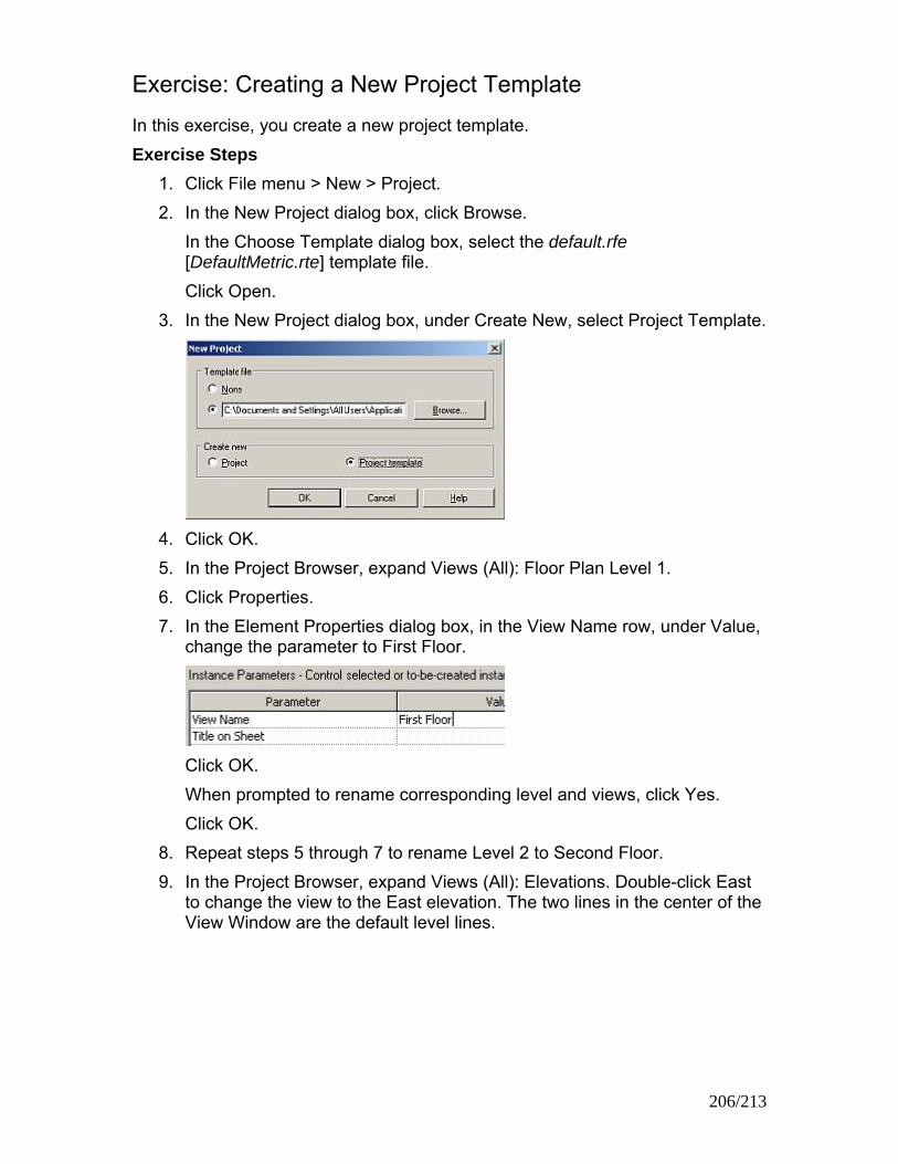
Exercise: Creating a New Project Template In this exercise, you create a new project template. Exercise Steps
1. Click File menu > New > Project. 2. In the New Project dialog box, click Browse.
In the Choose Template dialog box, select the default.rfe [DefaultMetric.rte] template file. Click Open.
3. In the New Project dialog box, under Create New, select Project Template.
4. Click OK. 5. In the Project Browser, expand Views (All): Floor Plan Level 1. 6. Click Properties. 7. In the Element Properties dialog box, in the View Name row, under Value,
change the parameter to First Floor.
Click OK. When prompted to rename corresponding level and views, click Yes. Click OK.
8. Repeat steps 5 through 7 to rename Level 2 to Second Floor. 9. In the Project Browser, expand Views (All): Elevations. Double-click East
to change the view to the East elevation. The two lines in the center of the View Window are the default level lines.
206/213

10. On the Design Bar, Basics tab, click Level. Place the cursor over the Second Floor level line near the left edge of the view window. A vertical green dashed line is displayed. Move up 10' 0" [4000mm]. Click to place the tail of the new level line.
Drag the level line right until it is over the head of the Second Floor level. A vertical green dashed line is displayed. Click to place the head of the new level line.
11. On the Toolbar, click Zoom In Region.
Drag a selection box around the right end of the level lines to zoom in on them.
12. On the Design Bar, click Modify. Select the level line you just drew.
Change its name to Roof.
When prompted to change the names of the corresponding views, click Yes.
13. Using the same techniques as in steps 2 through 4, add an additional level named Basement that is located 10' 0" [4000mm] below the First Floor level.
207/213

208/213
iew menu > New > Sheet. , select E1 30 x 42 Horizontal [A1
15. enu > New > Add View.
lan: First Floor.
16. n the cursor over the sheet. An outline of the
17. eet.
s. Sheet Name box, enter First Floor
14. Click VIn the Select a Titleblock dialog boxmetric]. Click OK. Click View mIn the Views dialog box, select Floor PClick Add View to Sheet. In the View Window, positioFirst Floor plan view is displayed at the tip of the cursor. Move the view to the center of the sheet. Click once to place the view in the sheet. Zoom in on the lower-right corner of the shClick the titleblock to highlight it. In the Options Bar, click PropertieIn the Element Properties dialog box,Plan.
Click OK.
18. s 14 through 17 to add drawing sheets for the Basement plan
ter Townhouse-3042.rte [Townhouse-A1.rte]
(.rte extension) is selected.
Exercise: Create a New Project Based on a Template
enu > New > Project.
Repeat stepview and the Second Floor plan view. Change the sheet names to Basement Plan and Second Floor Plan, respectively.
19. Click File menu > Save As. 20. In the Save As dialog box, en
as the name for the template. Make sure that the RTE file typeClick Save.
In this exercise, you start a new project based on a new template. Exercise Steps
1. Click File m2. In the New Project dialog box, click Browse.

3. In the Choose Template dialog box, select the Townhouse-3042.rte [Townhouse-A1.rte] template file. Click Open.
4. In the New Project dialog box, under Create New, click Project.
Click OK. Notice that the new project contains the levels and sheets that you created and modified in the previous steps.
5. Click File menu > Close to exit the project. Do not save any changes.
Exercise: Making Worksets Available In this exercise, you use worksets to subdivide a simple project for a team of four, each working on a different area of the project: the exterior, the interior layout, furniture placement, and wall section details. After worksets are made available, you create new worksets and add project elements to the correct worksets. You save the workset information to a Central Location file.
209/213

Exercise Steps 1. Open Imperial_Firestation.rvt (imperial) or Metric_Firestation.rvt (metric). 2. Click File menu > Worksets to make project sharing available.
Click OK to close the information dialog box. 3. In the Project Sharing - Worksets dialog box, click OK to accept the
default name, Workset1.
4. Two default worksets are created.
5. In the Worksets dialog box, click New.
In the New Workset dialog box, under Enter New Workset Name, enter Interior Layout.
Keep Visible by Default in All Views selected, because this workset includes the interior walls, which should appear in many views. Click OK.
6. In the Worksets dialog box, click New to create an additional workset. In the New Workset dialog box, Under Enter New Workset Name, enter Furniture Layout. Clear the Visible by Default in All Views check box, because furniture needs to be visible only in certain views.
210/213
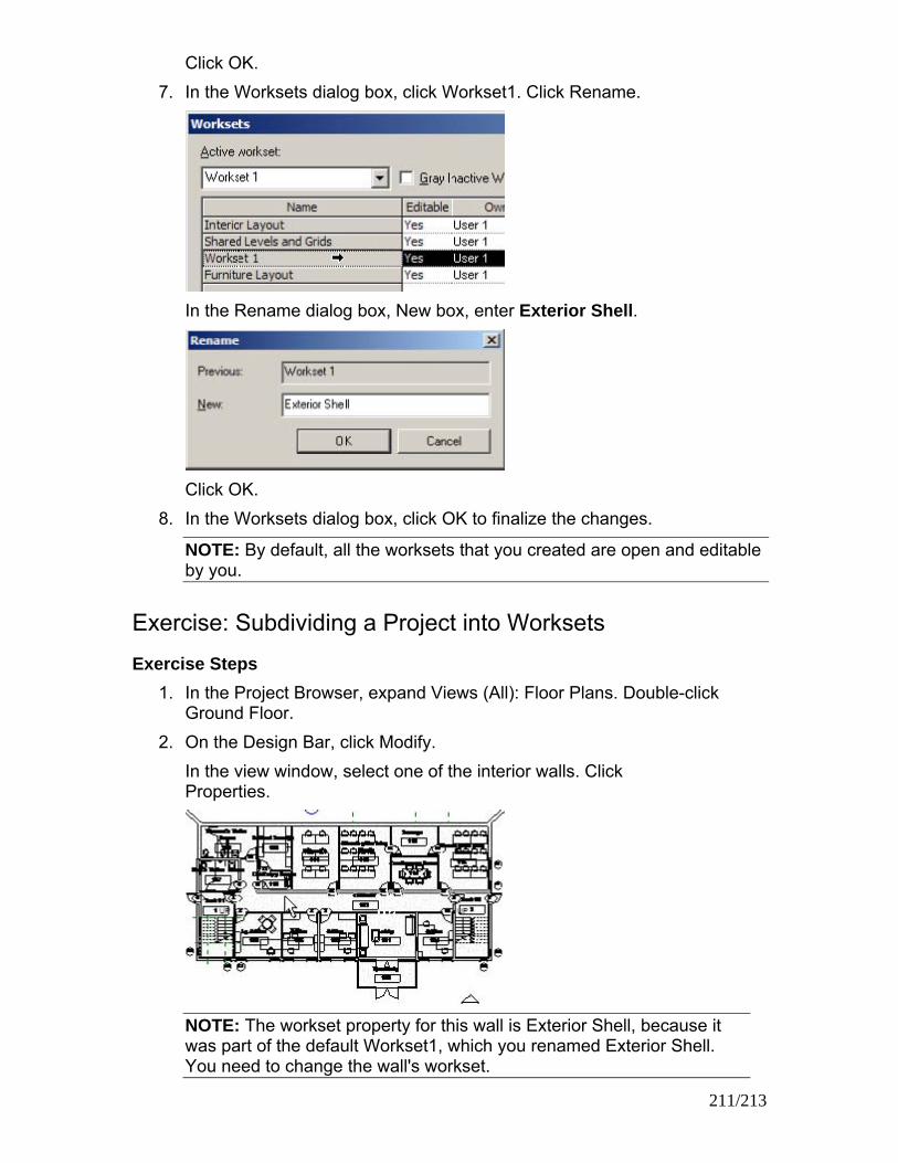
Click OK. 7. In the Worksets dialog box, click Workset1. Click Rename.
In the Rename dialog box, New box, enter Exterior Shell.
Click OK.
8. In the Worksets dialog box, click OK to finalize the changes.
NOTE: By default, all the worksets that you created are open and editable by you.
Exercise: Subdividing a Project into Worksets Exercise Steps
1. In the Project Browser, expand Views (All): Floor Plans. Double-click Ground Floor.
2. On the Design Bar, click Modify. In the view window, select one of the interior walls. Click Properties.
NOTE: The workset property for this wall is Exterior Shell, because it was part of the default Workset1, which you renamed Exterior Shell. You need to change the wall's workset.
211/213

3. In the Element Properties dialog box, Workset row, from the Value list, select Interior Layout to reassign the selected wall from the Exterior Shell workset to Interior Layout.
Click OK.
4. Enter VG to open the Visibility/Graphics dialog box. On the Model Categories tab, clear the Furniture, Furniture Systems, Plumbing Fixtures, and Specialty Equipment check boxes. On the Annotation Categories tab, clear the Show Annotation Categories in This View check box.
Click OK.
NOTE: It is easier to select multiple elements to change workset properties if you first hide the elements you do not want to select.
5. On the Design Bar, click Modify. Select all interior building elements right to left, as shown.
6. Click Properties.
NOTE: Because different types of elements are selected, the instance properties list is shorter.
212/213

In the Workset row, under Value, select Interior Layout.
Click OK.
7. Enter VG to open the Visibility/Graphics dialog box. On the Workset tab, clear the Interior Layout check box.
Click OK. The Ground Floor plan looks like the following illustration. Elements in the Interior Layout workset are not visible, which verifies that they were transferred. If any interior elements remain, select them and change their Workset value to Interior Layout.
8. In the View/Visibility dialog box, select the Interior Layout check box to turn visibility back on.
Exercise: Creating a Central Location File Exercise Steps
1. Click File menu > Save As to save the project as a Central Location file. In the Save As dialog box, name the file 01234_Central.rvt, where 01234 is the project number and Central indicates that it is the Central Location file. Click Save.
2. Click File menu > Worksets. 3. In the Worksets dialog box, in
each workset row, change Editable from Yes to No.
4. Close the project. Save it as 01234_Central.rvt.
213/213