Embed Size (px)
Citation preview

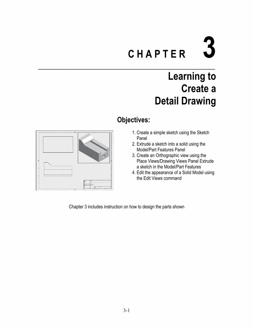
Autodesk Inventor 2015
A Tutorial Introduction
www.SDCpublications.comBetter Textbooks. Lower Prices.SDC
P U B L I C AT I O N S
Autodesk Inventor 2015A Tutorial Introduction
®
®
L. Scott Hansen, Ph.D.

Visit the following websites to learn more about this book:
Powered by TCPDF (www.tcpdf.org)
3-1
C H A P T E R 3 ________________________________________________________________
Learning to Create a
Detail Drawing
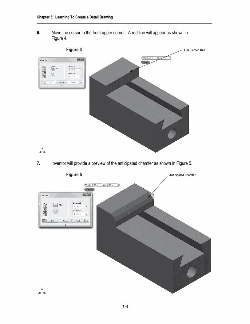
Objectives:
1. Create a simple sketch using the Sketch Panel 2. Extrude a sketch into a solid using the Model/Part Features Panel 3. Create an Orthographic view using the Place Views/Drawing Views Panel Extrude a sketch in the Model/Part Features 4. Edit the appearance of a Solid Model using the Edit Views command
Chapter 3 includes instruction on how to design the parts shown

Chapter 3: Learning To Create a Detail Drawing ______________________________________________________________________________________________
3-2
1. Start Autodesk Inventor 2015 by referring to “Chapter 1 Getting Started”. 2. After Autodesk Inventor 2015 is running, begin a new sketch. 3. Complete the drawing shown in Figure 1. Figure 1

Chapter 3: Learning To Create a Detail Drawing ______________________________________________________________________________________________
3-3
4. Move the cursor to the upper middle portion of the screen and left click on the drop down arrow under Fillet as shown in Figure 2.
Figure 2 Left Click Here
5. After selecting Chamfer, the Chamfer dialog box will appear. Left click on the “Two
Distance Chamfer” icon. Left click on the Edge icon as shown in Figure 3. Figure 3 Left Click Here
Chapter 3: Learning To Create a Detail Drawing ______________________________________________________________________________________________
3-4
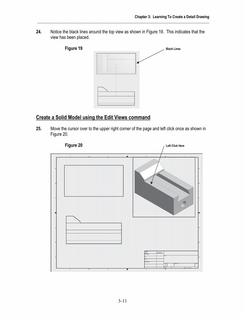
6. Move the cursor to the front upper corner. A red line will appear as shown in Figure 4. Figure 4 Line Turned Red
7. Inventor will provide a preview of the anticipated chamfer as shown in Figure 5. Figure 5 Anticipated Chamfer

Chapter 3: Learning To Create a Detail Drawing ______________________________________________________________________________________________
3-5
8. Move the cursor to Distance 1 in the dialog box and highlight the text. Enter .25 in the dialog box. Inventor will provide a preview of the chamfer as shown in Figure 6.
Figure 6 Enter .25 Here
9. Move the cursor to Distance 2 in the dialog box and highlight the text. Enter .1875 in the
dialog box. Inventor will provide a preview of the chamfer as shown in Figure 7. Figure 7 Left Click Here Enter .1875 Here

Chapter 3: Learning To Create a Detail Drawing ______________________________________________________________________________________________
3-6
10. Left click on OK. Your screen should look similar to Figure 8. Figure 8
11 Save the part file for easy retrieval to be used in the following section. Do not close the
part file. 12. After the part file has been saved, move the cursor to the upper left portion of the screen
and left click on the “New” icon as shown in Figure 9. Figure 9 Left Click Here

Chapter 3: Learning To Create a Detail Drawing ______________________________________________________________________________________________
3-7
Create an Orthographic view using the Drawing Views Panel 13. The Create New File dialog box will appear. Left click on the English folder. Left click on
the ANSI (in).idw. Left click on Create as shown in Figure 10. Figure 10 Left Click Here
14. Your screen should look similar to Figure 11. Figure 11

Chapter 3: Learning To Create a Detail Drawing ______________________________________________________________________________________________
3-8
15. Inventor is now in the Place Views Panel. Notice the commands at the top of the screen are now different. The width of the screen has been reduced to add instructional clarification.
16. Move the cursor to the upper left portion of the screen and left click on Base as shown in
Figure 12. Figure 12 Left Click Here
17. The drawing of the wedge block should appear attached to the cursor. Move the cursor
around to verify it is attached. If the part does not appear attached to the cursor, use the “Explore” icon to locate the part file as shown in Figure 13.
Figure 13 Left Click Here if Part is Not Attached to Cursor
Part Attached to Cursor

Chapter 3: Learning To Create a Detail Drawing ______________________________________________________________________________________________
3-9
18. Different views can be selected for the front, top, and side views. Select the desired view from the Orientation selection box as shown in Figure 14. To understand how the orientation selection works, left click on Top or Left to have the top view or left view as the front (base) view.
Figure 14 Left Click Here
19. Select the Front view for the base view. Left click on the Scale drop down box and set the
drawing scale to 4:1. The size of the wedge block will become larger as shown in Figure 15. Figure 15 Left Click Here

Chapter 3: Learning To Create a Detail Drawing ______________________________________________________________________________________________
3-10
20. Place the part just above the title block that is in the lower right corner of the screen and left click once. This will place the part as shown in Figure 16.
Figure 16 Left Click Here
21. If the part was inadvertently placed too low or too high, move the cursor over the dots that
surround the part, left click (holding the mouse button down), and drag the part to the desired location.
22. Move the cursor to the upper left portion of the screen and left click on Projected as shown in Figure 17. Figure 17 Left Click Here
23. The part will be attached to the cursor. Move the cursor upward and left click as shown in
Figure 18. Figure 18 Left Click Here
Chapter 3: Learning To Create a Detail Drawing ______________________________________________________________________________________________
3-11
24. Notice the black lines around the top view as shown in Figure 19. This indicates that the view has been placed.
Figure 19 Black Lines
Create a Solid Model using the Edit Views command 25. Move the cursor over to the upper right corner of the page and left click once as shown in
Figure 20. Figure 20 Left Click Here

Chapter 3: Learning To Create a Detail Drawing ______________________________________________________________________________________________
3-12
26. Move the cursor down to where the side view will be located and left click once as shown in Figure 21.
Figure 21 Left Click Here
27. Right click on the last view created (side view). A pop up menu will appear. Left click on
Create as shown in Figure 22. Figure 22 Left Click Here
Chapter 3: Learning To Create a Detail Drawing ______________________________________________________________________________________________
3-13
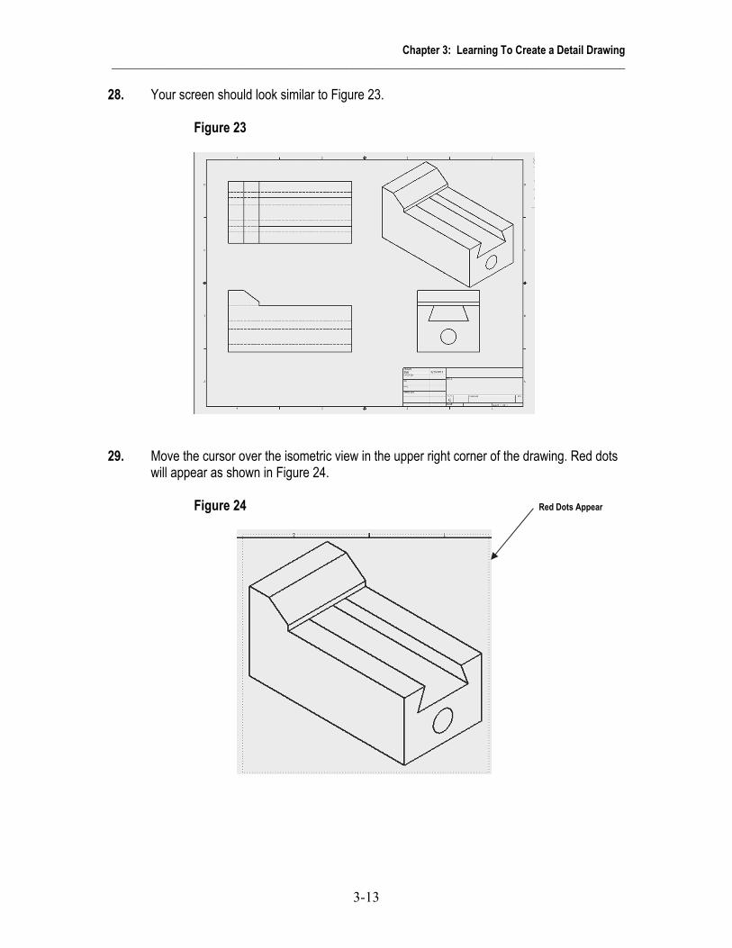
28. Your screen should look similar to Figure 23. Figure 23
29. Move the cursor over the isometric view in the upper right corner of the drawing. Red dots
will appear as shown in Figure 24. Figure 24 Red Dots Appear

Chapter 3: Learning To Create a Detail Drawing ______________________________________________________________________________________________
3-14
30. After the red dots appear, right click once. A pop up menu will appear. Left click on Edit View as shown in Figure 25.
Figure 25 Left Click Here
31. The Drawing View dialog box will appear. Left click on the “blue barrel” to the right under
Style. Left click on OK as shown in Figure 26. Figure 26 Left Click Here

Chapter 3: Learning To Create a Detail Drawing ______________________________________________________________________________________________
3-15
32. The isometric view will become a miniature solid model as shown in Figure 27. Figure 27
33. Your screen should look similar to Figure 28. Figure 28
Chapter 3: Learning To Create a Detail Drawing ______________________________________________________________________________________________
3-16
Chapter Problems
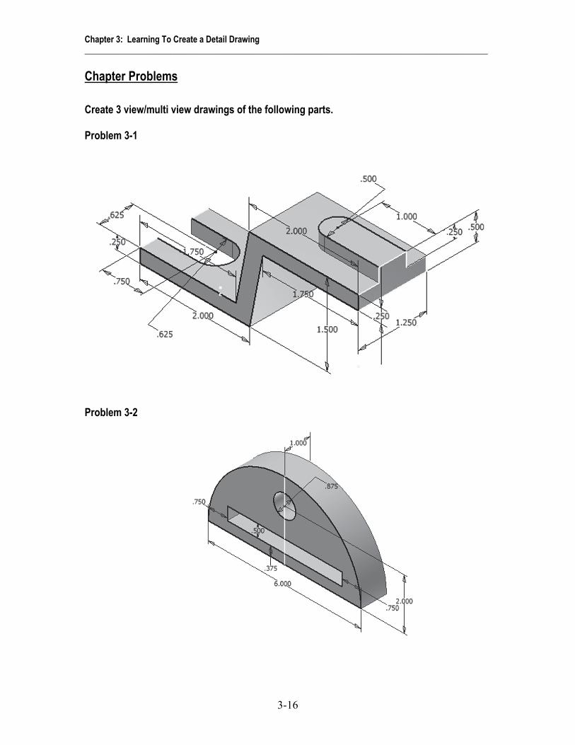
Create 3 view/multi view drawings of the following parts. Problem 3-1
Problem 3-2

Chapter 3: Learning To Create a Detail Drawing ______________________________________________________________________________________________
3-17
Problem 3-3
Problem 3-4 Hint: Use the 2 directional Extrude-Cut to create The 1.625 Diameter Hole

Chapter 3: Learning To Create a Detail Drawing ______________________________________________________________________________________________
3-18
Problem 3-5 Extrude .50 inches
Problem 3-6

Chapter 3: Learning To Create a Detail Drawing ______________________________________________________________________________________________
3-19
Problem 3-7 Extrude to .25 off of Base Extrude to .50 off of Base Extrude to .75 off of Base
Problem 3-8 Cut to 0.25 Depth