Embed Size (px)
Citation preview

OWNERS MANUAL4004H
REVISION 2/2000PART NO. 999997
SERIAL NO. __________________________
PO BOX 580697, TULSA, OK 74158-0697
4707 N. MINGO ROAD, TULSA, OK 74117-5904
PHONE (918) 836-0463
FAX (918) 834-5979
http://www.autocrane.com


WARNING! Federal law (49 cfr part 571) requires that the Final Stage Manufacturer ofa vehicle certify that the vehicle complies with all applicable federal regulations. Anymodifications performed on the vehicle prior to the final stage are also consideredintermediate stage manufacturing and must be certified as to compliance. The installer ofthis crane and body is considered one of the manufacturers of the vehicle. As such amanufacturer, the installer is responsible for compliance with all applicable federal andstate regulations, and is required to certify that the vehicle is in compliance.
WARNING! It is the further responsibility of the installer to comply with the OSHATruck Crane Stability Requirements as specified by 29 CFR part 1910.180 (C) (1).
WARNING! NEVER OPERATE THE CRANE NEAR ELECTRICALPOWER LINES! Death or serious injury will result from boom, line, or load contactingelectric lines. Do not use crane within 10 feet (3.05m) of electric power lines carrying up to50,000 volts. One foot additional clearance is required for every additional 30,000 volts or less.
WARNING! NEVER .............................v EXCEED load chart capacities (centerline of rotation to hoist hook).v un-reel last 5 wraps of cable from drum!v wrap cable around load!v attempt to lift or drag a load from the side! The boom can fail far below its rated capacity.v weld, modify, or use unauthorized components on any Auto Crane unit! This will void any
warranty or liability. Also failure of the crane may result.v place a chain link on the tip of the hook and try to lift a load!v use a sling bar or anything larger than the hook throat that could prevent the hook latch from
closing, thus negating the safety feature!v hold on any pendant Select Switch that will cause unsafe operating conditions!
WARNING! In using a hook with latch, ALWAYS make sure that the hook throat is closedbefore lifting a load! Proper attention and common sense applied to the use of the hoist hook andvarious slings will prevent possible damage to material being hoisted and may prevent injury topersonnel.
WARNING! Failure to correctly plumb and wire crane can cause inadvertent operation anddamage to crane and/or personnel!
WARNING! Auto Crane Company remote controlled cranes are not designed or intended tobe used for any applications involving the lifting or moving of personnel.
WARNING! ALWAYS operate the crane in compliance with the load capacity chart. Do not use the overload shutdown device to determine maximum rated loads, if your crane isequipped with this type of device.
warning 9/98
WARNINGS - READ THIS PAGE!

LAST PAGEWARRANTY20 . . . . . . . . . . . . . . . . . . . . . . . . . . . . . . . . . . . . . . . . . . . . . . . . .
9-1.0.0LOAD CHART19 . . . . . . . . . . . . . . . . . . . . . . . . . . . . . . . . . . . . . . . . . . . . . . . .
6-1.0.0HYDRAULIC SECTION18 . . . . . . . . . . . . . . . . . . . . . . . . . . . . . . . . . . . . . . . .
5-1.0.0ELECTRICAL SECTION17 . . . . . . . . . . . . . . . . . . . . . . . . . . . . . . . . . . . . . . .
4-1.0.0GENERAL DIMENSIONS16 . . . . . . . . . . . . . . . . . . . . . . . . . . . . . . . . . . . . . .
3-8.0.0TRAVELING BLOCK ASSEMBLY15 . . . . . . . . . . . . . . . . . . . . . . . . . . . . . .
3-7.0.0TURNER ASSEMBLY14 . . . . . . . . . . . . . . . . . . . . . . . . . . . . . . . . . . . . . . . . .
3-6.0.0AUTOMATIC SAFETY BRAKE13 . . . . . . . . . . . . . . . . . . . . . . . . . . . . . . . . .
3-5.0.0HOIST ACTUATOR ASSEMBLY12 . . . . . . . . . . . . . . . . . . . . . . . . . . . . . . . .
3-4.0.02-BLOCK ASSEMBLY11 . . . . . . . . . . . . . . . . . . . . . . . . . . . . . . . . . . . . . . . . .
3-1.0.0GENERAL ASSEMBLY (PEDESTAL)10 . . . . . . . . . . . . . . . . . . . . . . . . . . .
2-1.0.0INSTALLATION9 . . . . . . . . . . . . . . . . . . . . . . . . . . . . . . . . . . . . . . . . . . . . . .
1-8.0.0LUBRICATION & MAINTENANCE SCHEDULE8 . . . . . . . . . . . . . . . . . .
1-7.0.0SAFETY DECAL SECTION7 . . . . . . . . . . . . . . . . . . . . . . . . . . . . . . . . . . . .
1-6.0.0LIFE OF WIRE LINE / WIRE LINE LUBRICATION6 . . . . . . . . . . . . . . . .
1-5.0.0INSPECTION, TESTING, & MAINTENANCE5 . . . . . . . . . . . . . . . . . . . . .
1-4.0.0QUALIFICATIONS FOR OPERATORS4 . . . . . . . . . . . . . . . . . . . . . . . . . . .
1-3.0.0OPERATION OF UNIT / OUTRIGGERS 3 . . . . . . . . . . . . . . . . . . . . . . . . .
1-2.0.0OPERATING PRACTICES & WARNINGS2 . . . . . . . . . . . . . . . . . . . . . . . .
1-1.0.0INTRODUCTION1 . . . . . . . . . . . . . . . . . . . . . . . . . . . . . . . . . . . . . . . . . . . . .
4004H SERIES - OWNER'S MANUAL
TABLE OF CONTENTS
PAGE

DIMENSIONS
Width: 19.25 in (.49 m)Height: 32.50 in (.83 m)Length: 11 ft 8 5/16 in (3.58 m) Weight: 1050 lbs (476 kg) [Add 5 lbs (2.25 kg) for cable length of 75 feet (23 m)]
CAPACITY
16,000 ft lbs (2.31 ton/m)[ft lbs = horizontal distance from centerline ofrotation to free hanging weight (feet) x amountof weight (pounds)]
800201,45511
842191,60010
889181,7789
941172,0008
1,000162,2867
1,067152,6666
1,143143,2005
1,231134,0004
1,333124,0003
lbsftlbsft
LIFTING CAPACITIES
REACH
Main boom reaches 10 ftPower boom will extend to16 ftManual boom will extend to 20 ft
CABLE
80 ft (24.3 m) of 5/16 in diameter aircraftquality cable is standard [75 ft (22.86 m)optional].
CHASSIS REQUIREMENTS
10,500 lbs (4,763 kg) GVWR minimum
HYDRAULIC SYSTEM
Pressure: 2200psi (15,169 kPa) relief setting
Flow: 5 gpm (19 lpm)
Filtration: High pressure 10 micron in manifold
Oil Type: 10w Hydraulic Oil [Mobile DTE 13, Sun 2015, Dextron II]
MOVEMENT SPEEDS: (Proportional Maximum)
Hoist: 34 fpm single line (no load) 31 fpm single line (1000 lbs)
Boom Up: 9 secBoom Down: 8 secExtend Out: 11 secExtend In: 9 secRotation: 40 sec/revolution
ELECTRICAL SYSTEMREQUIREMENTS
Control voltage: 12 volt DCAlternator: 90 amp (minimum)Battery: 100 minute reserve capacity (minimum) Maintenance type
GENERAL SPECIFICATIONS4004H SERIES
1-1.1.0 4HSPEC 8/98

Auto Crane products are designed to provide many yearsof safe, trouble-free, dependable service when properly usedand maintained.
To assist you in obtaining the best service from yourcrane and to avoid untimely crane and/or vehicle failure, thismanual provides the following operating and serviceinstructions. It is specifically recommended that alloperating and service personnel consider this manual asmandatory material for reading and study before operating orservicing Auto crane products. It is highly recommendedthat crane owners, equipment managers and supervisors alsoread this manual.
Auto Crane has incorporated several safety features inthe 4004EH series cranes for your protection. The choice ofmaterials and the design of the electrical system minimizesweight and lengthens durability. The hydraulic componentsmeet or exceed a 3.5:1 safety factor. Holding valves preventthe load from dropping if a hose should fail. The reservoirhas a 40u air filter in the filler cap. The pump has a 100mesh strainer in the suction line.
For your convenience the overall dimensions of the4004H series crane are in the General Dimension Section.Maximum turning radius at both the hoist motor and therotation motor are also on that drawing.
Remember, the crane adds weight to the vehicle.Adding weight may change the driving and ridingcharacteristics of the vehicle unless the appropriate overloadspring(s) are installed on the truck. The payload of thevehicle is reduced by the weight of the crane. The operatorshould exercise care when loading the vehicle. Distributingthe payload on the vehicle evenly will greatly improve thedriving and riding characteristics of the vehicle. A minimumG.V.W. of 10,500 lbs. with two rear jacklegs (oroutriggers) is recommended for mounting the 4004Hseries cranes.
The 4004H series cranes are attached directly to your 12volt truck electrical system. The power cable and retainingclips are included with the crane. A typical power cablemounting and hookup is shown in the installation section. The performance of your new crane depends on the truckelectrical system. The use of maintenance free batteries isNOT recommended for use with any Auto Crane product.The recommended alternator and battery that will give thelongest life with the most useful duty cycle is a 60 amp.alternator with a 120 minute reserve capacity, deep cyclebattery. These specifications should be considered minimum.
Auto Crane Company issues a limitedwarranty certificate with each unit sold.See last page for warranty policy.
It has always been Auto Crane Company policy to handleall warranty claims we receive as promptly as possible. If awarranty claim involves discrepant material or workmanship,Auto Crane will take immediate corrective action. It isunderstandable that Auto Crane company cannot assumeresponsibility of liability when it is obvious that our productshave been abused, mis-used, overloaded or otherwisedamaged by inexperienced persons trying to operate theequipment without reading the manual.
Auto Crane will not assume responsibility orliability for any modifications or changes made tounit, or installation of component parts done withoutauthorization.
Auto Crane maintains a strong distributor network and aknowledgeable Customer Service Department. In most cases,an equipment problem is solved via phone conversation withour customer service department. The customer servicedepartment also has the ability to bring a local distributor, aregional sales manager, or a factory serviceman into thesolution of an equipment problem. If, through no fault ofAuto crane company, it is necessary to send an experiencedfactory serviceman on a field service call, the rates stated inthe Auto Crane Distributor's Flat Rate Manual will apply.
Auto Crane Company's extensive Research andDevelopment Program allow our customers to use the bestequipment on the market. Our Engineering Staff and ourknowledgeable sales people, are always available to ourcustomers in solving crane and winch-type applicationproblems. When in doubt, call the Auto Crane factory.
DISTRIBUTOR ASSISTANCE:Should you require any assistance not given in this
manual, we recommend that you consult your nearest AutoCrane Distributor. Our distributors sell authorized parts andhave service departments that can solve almost any neededrepair.
NOTE: THIS MANUAL SHOULD
REMAIN WITH THE CRANE AT ALLTIMES.
This manual does not cover all maintenance, operating,or repair instructions pertinent to all possible situations. Ifyou require additional information, please contact the AutoCrane Company at the following telephone number: (918)836-0463. The information contained in the manual is ineffect at the time of this printing. Auto Crane Companyreserves the right to update this material without notice orobligation.
4HINTRO 6/98
INTRODUCTION4004H SERIES
1-1.0.0

1. Make certain the vehicle meets minimum chassisrequirements. (These requirements do not guaranteeunit stability)
2. Make certain the crane is installed per factoryspecifications. Contact your local Distributor or theAuto Crane factory if any questions arise.
3. Keep the vehicle in as level a position as possiblewhile loading or unloading.
4. ALWAYS set the vehicle emergency brake beforebeginning crane operations.
5. ALWAYS use outriggers from vehicle to the groundduring crane operation. Make sure they are firmlypositioned on solid footings.
6. All load ratings are based on crane capacity, NOTtruck/crane stability.
7. Keep objects and personnel clear of crane path duringoperation.
8. Keep hoist cable pulled tight at all times.
9. REMEMBER, in lifting a heavy load, the weight cancreate enough tipping momentum to overturn thevehicle.
10. ALWAYS keep load as close to ground as possible.
11. Oil gears as required.
12. Periodic adjustment of hoist worm brake may berequired (see automatic safety brake drawing in thismanual).
13. Hydraulic hoses need to be inspected frequently forsigns of deterioration, and be replaced as required.
14. The hoist hook is an important item that an operatorshould consider and use properly. It should bechecked on a daily basis for distortion or cracks.
15. ALWAYS store outriggers before road travel.
16. WARNING! NEVER OPERATE THE CRANENEAR ELECTRICAL POWER LINES! Death orserious injury will result from boom, line, or loadcontacting electric lines. Do not use crane within 10feet (3.05m) of electric power lines carrying up to50,000 volts. One foot additional clearance isrequired for every additional 30,000 volts or less.
17. WARNING! NEVER EXCEED load chartcapacities (centerline of rotation to hoist hook).
18. WARNING! NEVER un-reel last 5 wraps of cablefrom drum!
19. WARNING! NEVER wrap cable around load!
20. WARNING! NEVER attempt to lift or drag a loadfrom the side! The boom can fail far below its ratedcapacity.
21. WARNING! NEVER weld, modify, or useunauthorized components on any Auto Crane unit!This will void any warranty or liability. Also failureof the crane may result.
22. WARNING! NEVER place a chain link on the tipof the hook and try to lift a load!
23. WARNING! NEVER use a sling bar or anythinglarger than the hook throat that could prevent thehook latch from closing, thus negating the safetyfeature!
24. WARNING! In using a hook with latch, ALWAYSinsure that the hook throat is closed before lifting aload! Proper attention and common sense applied tothe use of the hoist hook and various slings willprevent possible damage to material being hoisted andmay prevent injury to personnel.
25. WARNING! NEVER hold any pendant SelectSwitch on that will cause unsafe operating conditions!
--- IMPORTANT --- OPERATING PRACTICES & WARNINGS
WARNING!Auto Crane Company remote controlled, stiff boom cranesare not designed or intended to be used for any applicationsinvolving the lifting or moving of personnel.
1-2.0.0 SAFTIPS 2/98

26. Make sure this manual has been thoroughly read byall crane operating personnel and supervisors.
27. A routine inspection of the crane should be mandatorybefore each operating day. Any defects should becorrected immediately.
28. At a job site the vehicle should be positioned so thatthe crane can adequately reach the load within therated capacity (centerline of rotation to hoist hook).
29. Keep the vehicle as level as possible during operation.
30. For electric cranes, engage emergency brake andleave ignition on with transmission in neutral (or inpark for automatic transmissions). Activate any cranepower switches. For Auto Crane units requiringbattery and hydraulic operation, engage emergencybrake, place gear selector in neutral, press clutch,activate PTO, release clutch and after hydraulic fluidis warm, set throttle control to proper engine speed.
31. Always use outriggers from the truck to the ground.Be sure these are firm and adequately positioned.When rotating, keep load as low to the ground aspossible.
32. Remove pendant control from cab or storage area. Onsmaller units, plug pendant into receptacle on crane.On larger units, remove pendant control from guardand unwrap cable from boom. Do not operate craneuntil cable is unwound completely. On all cranes,detach hook from dead man. Crane is now ready foroperation.
33. Always boom up before rotating so the boom willclear the required boom support.
34. When extending the boom, always maintain clearancebetween the boom crown and the traveling block orhoist hook.
35. Always observe safe and practical operation to avoidpossible accidents. Refer to Safety Tips andPrecautions.
36. After completing lifting operations, return the boomto stowed position on the boom support. Avoidunneeded pressure on the boom support.
37. Store pendant control on proper location (in cab or oncrane).
38. Return outriggers to stowed position. Make sure theyare pinned in place or jacklegs are returned tocompartment.
39. Check work area for any tools or equipment notstored.
40. Release throttle control, depress clutch and disengagePTO. Deactivate any crane power switches.
41. Report any unusual occurrence during crane operationthat may indicate required maintenance or repair.
42. NEVER use two cranes to support a load too large foreither crane.
43. Spray all electrical equipment with special corrosionresistant coating. This eliminates rust or corrosiondue to melting and freezing action of condensation.
1-3.0.0OPER 2/98
--- IMPORTANT --- OPERATION OF UNIT
OPERATION OF OUTRIGGERS
For hydraulic outriggers:1. Shift crane/outrigger control valve to "outrigger"
position.2. While operating the outrigger control valves
(located on the outrigger cylinders)simultaneously operate the boom-up controlswitch. This will allow the hydraulic system tobuild pressure.
3. After outriggers are positioned, returncrane/outrigger selector to "crane" position.
4. Crane is now ready to operate.
For manual outriggers:1. Pull lock pins to release jack leg or drop down
outrigger and move to outermost lock position.2. Make sure lock pins are reinstalled properly.3. Lower outrigger pad to firm ground and adjust
foot to take out slack.4. Crane is now ready to operate.

OPERATORS
1 Crane operation shall be limited to personnel withthe following minimum qualifications:
A. designated persons
B. trainees under the direct supervision of a designatedperson
C. maintenance and test personnel (when it isnecessary in the performance of their duties)
D. inspectors (crane).
2 No one other than the personnel specified above shallenter the operating area of a crane with the exceptionof persons such as oilers, supervisors, and thosespecified persons authorized by supervisors whoseduties require them to do so and then only in theperformance of their duties and with the knowledgeof the operator or other persons.
QUALIFICATIONS FOR OPERATORS
3 Operators shall be required by the employer to pass apractical operating examination. Qualifications shallbe limited to the specific type of equipment for whichexamined.
4 Operators and operator trainees shall meet thefollowing physical qualifications:
A. Vision of at least 20/30 Snellen in one eye and20/50 in the other, with or without corrective lenses.
B. Ability to distinguish colors, regardless of position,if colors differentiation is required for operation.
C. Adequate hearing with or without hearing aid forthe specific operation.
5 Evidence of physical defects or emotional instabilitywhich render a hazard to operator or others, whichin the opinion of the examiner could interfere withthe operator's performance may be sufficient causefor disqualification. In such cases, specialized clinicalor medical judgment and tests may be required.
6 Evidence that the operator is subject to seizures orloss of physical control shall be sufficient reason fordisqualification. Specialized medical tests may berequired to determine these conditions.
7 Operators and operator trainees should have normaldepth perception, coordination, and no tendencies todizziness or similar undesirable characteristics.
8 In addition to the above listed requirements, theoperator shall:
A. Demonstrate the ability to comprehend and interpretall labels, operator's manuals, safety codes and otherinformation pertinent to correct crane operations.
B. Possess knowledge of emergency procedures andimplementation of same.
C. Demonstrate to the employer the ability to operatethe specific type of equipment.
D. Be familiar with the applicable safety regulations.
E. Understand responsibility for maintenancerequirements of crane.
F. Be thoroughly familiar with the crane and itscontrol functions.
G. Understand the operating procedures as outlined bythe manufacturer.
CONDUCT OF OPERATORS
9 The operator shall not engage in any practice whichwill divert his attention while actually operating thecrane.
10 Each operator shall be responsible for thoseoperations under the operator's direct control.Whenever there is any doubt as to safety, theoperator shall consult with the supervisor beforehandling the loads.
11 The operator should not leave a suspended loadunattended unless specific precautions have beeninstituted and are in place.
12 If there is a warning sign on the switch or enginestarting controls, the operator shall not close theswitch or start the engine until the warning sign hasbeen removed by the appointed person.
13 Before closing the switch or starting the engine, theoperator shall see that all controls are in the "OFF"or neutral position and all personnel are in the clear.
14 If power fails during operation, the operator shall:
A. move power controls to the "OFF" or neutralposition.
QUALIFICATIONS FOR AND CONDUCT OF OPERATORS AND
OPERATING PRACTICES
QUAL 7/981-4.0.0

B. land the suspended load and boom, if practical.
15 The operator shall be familiar with the equipmentand its proper care. If adjustments or repairs arenecessary, the operator shall report the samepromptly to the appointed person, and shall alsonotify the next operator.
16 All controls shall be tested by the operator at thestart of each shift. If any controls do not operateproperly, they shall be adjusted or repaired beforeoperations are begun.
17 Stabilizers shall be visible to the operator whileextending or setting unless operator is assisted by asignal person.
OPERATING PRACTICES
HANDLING THE LOAD
18 Size of load
A. No crane shall be loaded beyond the rated loadexcept for test purposes.
B. The load to be lifted is to be within the rated load ofthe crane and its existing configuration.
C. When loads which are not accurately known are tobe lifted, the person responsible for the job shallascertain that the weight of the load does not exceedthe crane rated load at the radius at which the loadis to be lifted.
19 Attaching the load
A. The load shall be attached to the hook by means ofslings or other devices of sufficient capacity.
B. Hoist rope shall not be wrapped around the load.
20 Moving the load
A. The operator shall determine that:
B. The crane is level and, where necessary, thevehicle/carrier is blocked properly.
C. The load is well secured and balanced in the sling orlifting device before it is lifted more than a fewinches.
D. Means are provided to hold the vehicle stationarywhile operating the crane.
E. Before starting to lift, the hook shall brought overthe load in such a manner as to minimize swinging.
F. During lifting care shall be taken that:
1. there is no sudden acceleration ordeceleration of the moving load.
2. load, boom or other parts of the crane donot contact any obstruction.
G. Cranes shall not be used for dragging loadssideways.
H. This standard recognizes that articulating boomcranes are designed and intended for handlingmaterials. They do not meet personnel lift orelevator requirements. Therefore, no lifting,lowering, swinging or traveling shall be done whilea person is on the hook or load. Hook attachedsuspended work platforms (baskets) shall not beused with cranes covered by this standard. Workplatforms attached to the boom must be approved bycrane manufacturer.
I. The operator should avoid carrying loads overpeople.
J. When the crane is so equipped, the stabilizers shallbe fully extended and set. Blocking under stabilizersshall meet the requirements as follows:
1. strong enough to prevent crushing.
2. of such thickness, width and length as tocompletely support the stabilizer pad.
K. Firm footing under all tires, or individual stabilizerpads should be level. Where such a footing is nototherwise supplied, it should be provided bytimbers, cribbing, or other structural members todistribute the load so as to not exceed allowablebearing capacity or the underlying material.
L. In transit, the boom shall be carried in stowedposition.
M. When rotating the crane, sudden starts and stopsshall be avoided. rotational speed shall be such thatthe load does not swing out beyond the radius atwhich it can be controlled.
N. The crane shall not be transported with a load onthe hook unless recommended by the manufacturer.
O. No person should be permitted to stand or passunder a suspended load.
21 Stowing procedure. Follow the manufacturer'sprocedure and sequence when stowing andun-stowing the crane.
QUALIFICATIONS FOR AND CONDUCT OF OPERATORS AND
OPERATING PRACTICES
QUAL 7/981-4.1.0

MISCELLANEOUS
OPERATING NEAR ELECTRICAL POWERLINES
22 Cranes shall be operated so that no part of the craneor load enters into the danger zone shown above.
EXCEPTIONS
A. The danger zone may be entered after confirmationby an appointed person that the electricaldistribution and transmission lines have beende-energized and visibly grounded at the point ofwork; or
B. The danger zone may be entered if insulatingbarriers (not a part of nor an attachment to thecrane) have been erected to prevent physical contactwith the lines.
23 For lines rated 50 kV or below, minimum clearancebetween the lines and any part of the crane or load(including handling appendages) shall be 10 ft. (3m).For higher voltages, see Table 1.
24 Caution shall be excercised when working nearoverhead lines, because they can move horizontally orvertically due to wind, moving the danger zone to newpositions.
25 In transit with no load and boom lowered theclearance shall be specified in Table 1.
26 A qualified signalperson shall be assigned to observethe clearance and give warning before approachingthe above limits.
A. Any overhead wire shall be considered to be anenergized line unless and until the person owningsuch line or the electrical utility authorities verifythat it is not an energized line.
B. Exceptions to this procedure, if approved by theadministrative or regulatory authority if thealternate procedure provides equivalent protectionand set forth in writing.
C. Durable signs shall be installed at the operator'sstation and on the outside of the crane, warning thatelectrocution or serious bodily injury may occurunless a minimum clearance of 10 ft. (3.0m)between the crane or the load being handled andenergized power lines. Greater clearances arerequired because of higher voltage as stated above.These signs shall be revised but not removed whenlocal jurisdiction requires greater clearances.
QUALIFICATIONS FOR AND CONDUCT OF OPERATORS AND
OPERATING PRACTICES
QUAL 7/981-4.2.0
(6.1)20over 750 to 1000
(4.87)16over 345 to 750
(3.83)10over 50 to 345
(1.83)6over 0.75 to 50
(1.22)4over to 0.75
while in transit with no load and boom lowered
(13.72)45over 750 to 1000
(10.67)35over 500 to 750
(7.62)25over 350 to 500
(6.1)20over 200 to 350
(4.6)15over 50 to 200
(3.05)10over to 50
when operating near high voltage power lines
(m)ft(phase to phase)normal voltage, kV
clearance
minimum required
TABLE 1

INSPECTION CLASSIFICATION
27 Initial inspection. Prior to initial use, all new, altered,modified or extensively repaired cranes shall beinspected by a designated person to insure compli-ance with provisions of this standard.
28 Regular inspection. Inspection procedure for cranesin regular service is divided into two general classifi-cations based upon the intervals at which inspectionshould be performed. The intervals in turn aredependent upon the nature of the components of thecrane and the degree of their exposure to wear,deterioration, or malfunction. The two general classi-fications are herein designated as "frequent" and"periodic" with respective intervals between inspec-tions as defined below.
A. frequent inspection - daily to monthly intervals
B. periodic inspection - one to twelve intervals, or asspecifically recommended by the manufacturer
FREQUENT INSPECTION
29 Inspection shall be performed by designatedpersonnel.
A. control mechanisms for maladjustment interferingwith proper operation - daily, when used
B. control mechanisms for excessive wear of compo-nents and contamination by lubricants or otherforeign matter
C. safety devices for malfunction
D. all hydraulic hoses, particularly those which flex innormal operation of crane functions, should bevisually inspected once every working day, whenused
E. hooks and latches for deformation, chemicaldamage, cracks, and wear. Refer to ANSI/ASMEB30.10
F. rope reeving for compliance with crane manufac-turer's specifications, if optional winch is used
G. electrical apparatus for malfunctioning, signs ofexcessive deterioration, dirt and moisture accumula-tion
H. hydraulic system for proper oil level and leaks daily
I. tires for recommended inflation pressure, cuts andloose wheel nuts
J. connecting pins and locking device for wear anddamage
PERIODIC INSPECTION
30 Deformed, cracked or corroded members in thecrane structure and carrier.
31 Loose bolts, particularly mounting bolts.
32 Cracked or worn sheaves and drums.
33 Worn, cracked, or distorted parts such as pins,bearings, shafts, gears, rollers and devices.
34 Excessive wear on brake and clutch system parts andlining.
35 Crane hooks inspected for cracks.
36 Travel steering, braking, and locking devices, formalfunction.
37 Excessively worn or damaged tires.
38 Hydraulic and pneumatic hose, fittings, and tubinginspection.
A. evidence of leakage at the surface of the flexiblehose or its junction with metal and coupling
B. blistering, or abnormal deformation to the outercovering of the hydraulic or pneumatic hose
C. leakage at threaded or clamped joints that cannot beeliminated by normal tightening or recommendedprocedures
D. evidence or excessive abrasion or scrubbing on theouter surface of a hose, rigid tube, or fitting. Meansshall be taken to eliminate the interference of
INSPECTION, TESTING AND MAINTENANCE
GENERAL
INSP 9/981-5.0.0

elements in contact or otherwise protect thecomponents
39 Hydraulic and pneumatic pumps and motorsinspection.
A. loose bolts or fasteners
B. leaks at joints between sections
C. shaft seal leaks
D. unusual noises or vibrations
E. loss of operating speed
F. excessive heating of the fluid
G. loss of pressure
40 Hydraulic and pneumatic valves inspection.
A. cracks in valve housing
B. improper return of spool to neutral position
C. leaks at spools or joints
D. sticking spools
E. failure of relief valves to attain or maintain correctpressure setting
F. relief valve pressure shall be checked as specified bythe manufacturers
41 Hydraulic and pneumatic cylinders inspection.
A. drifting caused by fluid leaking across piston
B. rod seals leaking
C. leaks at welding joints
D. scored, nicked, or dented cylinder rods
E. damaged case (barrel)
F. loose or deformed rod eyes or connecting joints
42 Hydraulic filters. Evidence of rubber particles on thefilter elements may indicate hose, "O" ring, or otherrubber component deterioration. Metal chips orpieces on the filter may denote failure in pumps,motors, or cylinders. Further checking will be
necessary to determine origin of the problem beforecorrective action can be taken.
43 Labels are to be in place and legible.
CRANES NOT IN REGULAR USE
44 A crane which has been idle for a period of over onemonth or more, but not less than six months, shall begiven an inspection conforming with the initial-regular- frequent inspections.
45 A crane which has been idle for a period of over sixmonths shall be given a complete inspection conform-ing with the initial-regular-frequent inspectionrequirements.
INSPECTION RECORDS
46 Dated records for periodic inspection should be madeon critical items such as brakes, crane hooks, rope,hydraulic and pneumatic cylinders, and hydraulicand pneumatic relief pressure valves. Records shouldbe kept available to an appointed person.
OPERATIONAL TESTS
47 Prior to initial use, all new, altered, modified, orextensively repaired cranes shall be tested for compli-ance with the operational requirements of thissection, including functions such as the following:
A. load lifting and lowering mechanisms
B. boom lifting and lowering mechanisms
C. boom extension and retraction mechanisms
D. swing mechanisms
E. safety devices
F. operating controls comply with appropriate functionlabels
Operational crane test results shall be madeavailable to an appointed person.
RATED TEST LOADPrior to initial use, altered, modified, orextensively repaired cranes shall be load
INSPECTION, TESTING AND MAINTENANCE
GENERAL
INSP 9/981-5.1.0

tested by or under the direction of anappointed person.
48 Test loads shall not exceed 110% of the manufac-turer's load ratings.
49 Written reports shall be maintained showing testprocedures and confirming the adequacy of repairs.
MAINTENANCE
PREVENTIVE MAINTENANCE
50 Before adjustment and repairs are started on a crane,the following precautions shall be taken asapplicable:
A. crane placed where it will cause the least interfer-ence with other equipment or operations
B. all controls at the "off" position
C. starting means rendered inoperative
D. boom lowered to the ground if possible or otherwisesecured against dropping
E. relieve hydraulic oil pressure from all hydrauliccircuits before loosening or removing hydrauliccomponents
51 Warning or "OUT OF ORDER" signs shall be placedon the crane controls.
52 After adjustments and repairs have been made, thecrane shall not be returned to service until all guardshave been reinstalled, trapped air removed fromhydraulic system (if required), safety devices reacti-vated, and maintenance equipment removed.
ADJUSTMENTS AND REPAIRS
53 Any hazardous conditions disclosed by the inspectionrequirements shall be corrected before operation ofcrane is resumed, Adjustments and repairs shall bedone only by designated personnel.
54 Adjustments shall be maintained to assure correctfunctioning of components, The following areexamples:
A. functional operating mechanism
B. safety devices
C. control systems
55 Repairs or replacements shall be provided as neededfor operation.
The following are examples:
A. critical parts of functional operating mechanismswhich are cracked, broken, corroded, bent, or exces-sively worn
B. critical parts of the crane structure which arecracked, bent, broken, or excessively corroded
C. crane hooks showing cracks, damage, or corrosionshall be taken out of service. Repairs by welding arenot recommended
56 Instructions shall be provided by the manufacturerfor the removal of air from hydraulic circuits.
LUBRICATIONAll moving parts of the crane, for whichlubrication is specified, should be regularlylubricated per the manufacturer'srecommendations and procedures.
ROPE INSPECTION
57 Frequent Inspection
A. All running ropes in service should be visuallyinspected once each working day. A visual inspec-tion shall consist of observation of all rope whichcan be in use during the days operations. Thesevisual observations should be considered withdiscovering gross damage such as listed below,which may be an immediate hazard.
1. distortion of the rope such as kinking,crushing, un-stranding, birdcaging, mainstrand displacement, or core protrusion.Loss of rope diameter in a short length orunevenness of outer strands should bereplaced
2. general corrosion
INSPECTION, TESTING AND MAINTENANCE
GENERAL
INSP 9/981-5.2.0

3. broken or cut strands;
4. number, distribution and type of visiblebroken wires. When such damage isdiscovered, the rope shall either beremoved from service or given asinspection.
B. Care shall be taken when inspecting sections ofrapid deterioration such as flange points, crossoverpoints, and repetitive pickup points on drums.
58 Periodic inspection
A. The inspection frequency shall be determined by aqualified person and shall be based on such factorsas:
1. expected rope life as determined byexperience on the particular installation orsimilar installations
2. severity of environment
3. percentage of capacity lifts
4. frequency rates of operation
5. exposure to shock loads
Inspection need not be at equal calendarintervals and should be more frequent as therope approaches the end of it's service life.This inspection shall be made at leastannually.
B. Periodic inspection shall be performed by a desig-nated person. This inspection shall cover the entirelength of the rope. Only the surface wires need beinspected. No attempt should be made to open therope. Any deterioration results in appreciable loss oforiginal strength, such as described below, shall benoted and determination made as to whether use ofthe rope would constitute a hazard: points listedabove reduction of rope diameter below nominaldiameter due to loss of core support, internal orexternal corrosion, or wear of outside wires;severely corroded, cracked, bent, worn or improp-erly applied connections;
C. Care shall be taken when inspecting sections subjectto rapid deterioration such as the following:
1. sections in contact with saddles, equalizersheaves, or other sheaves where rope travelis limited
2. sections of the rope at or near terminal endswhere corroded or broken wires mayprotrude
ROPE REPLACEMENT
59 No precise rules can be given for determination of theexact time for replacement of rope, since manyvariable factors are involved.
Continued use in this respect depends upongood judgement by a designated person inevaluating remaining strength in a used ropeafter allowance for deterioration disclosed byinspection. Continued rope operation dependsupon this remaining strength.
60 Conditions such as the following shall be reason forquestioning continued use of the rope or increasingthe frequency of inspection:
A. in running ropes, six randomly distributed brokenwires in one lay or three broken wires in one strandin one lay
B. one outer wire broken at the contact point with thecore of the rope structure and protrudes or loops outof the rope structure. Additional inspection of thissection is required
C. wear of one third of the original diameter of theoutside individual wire
D. kinking, crushing, birdcaging, or any other damageresulting in distortion of the rope structure
E. evidence of any heat damage from any cause
F. reduction from nominal diameter of more than 1/64in. (0.4mm) for diameters up to and including 5/16in. (8 mm), 1/32 in. (0.8 mm) for diameter 3/8 in.(9.5 mm) to and including 1/2 in. (13 mm), 3/64 in.(1.2 mm) for diameter 9/16 in. (14.5 mm) to andincluding 3/4 in. (19 mm). 1/16 in. (1.6 mm) fordiameter 7/8 in. (22 mm) to and including 11/8 in.(29 mm), 3/32 in. (2.4 mm) for diameters 11/4 in.(32 mm) to and including 11/2 in. (38 mm)
INSPECTION, TESTING AND MAINTENANCE
GENERAL
INSP 9/981-5.3.0

G. In standing ropes, more than two broken wires inone lay in sections beyond end connections or morethan one broken wire at an end connection.
H. Replacement rope shall have a strength rating atleast as great as the original rope furnished orrecommended by the crane manufacturer. Anydeviation from the original size, grade, or construc-tion shall be specified by a rope manufacturer, or aqualified person.
61 Rope not in regular use: all rope which has been idlefor a period of a month or more due to shutdown orstorage of a crane on which it is installed, shall begiven and inspection in accordance with above infor-mation before it is placed in service. This inspectionshall be for all types of deterioration and shall beperformed by a qualified person.
62 Inspection records
A. frequent inspection- no records required
B. periodic inspections- in order to establish data as abasis for judging the proper time for replacement, adated report condition at each periodic inspectionshould be kept on file. This report shall cover points of deterioration listed above.
ROPE MAINTENANCE
63 Rope should be stored to prevent damage ordeterioration.
64 Unreeling or uncoiling of rope shall be done asrecommended by the rope manufacturer and withcare to avoid kinking or inducing twist.
65 Before cutting a rope, seizing shall be placed on eachside of the place where the rope is to be cut to preventunlaying of the strands. On pre-formed rope, oneseizing on each side of the cut is required. Onnon-preformed ropes of 7/8 in. (22 mm) diameter orsmaller, two seizings on each side of the cut arerequired, and for non-preformed rope 1 in. (25 mm)diameter or larger, three seizings on each side of thecut are required.
66 During installation care should be exercised to avoiddragging of the rope in the dirt or around objectswhich will scrape, nick crush or induce sharp bendsin it.
67 Rope should be maintained in a well-lubricatedcondition. It is important that lubricant applied as apart of a maintenance program shall be compatiblewith the original lubricant and to this end the ropemanufacturer should be consulted. Lubricant appliedshall be the type which does not hinder visual inspec-tion. Those sections of rope which are located oversheaves or otherwise hidden during inspection andmaintenance procedures require special attentionwhen lubricating rope. The object of rope lubricationis to reduce internal friction and to prevent corrosion.
68 When an operating rope shows greater wear or welldefined localized areas than on the remainder of therope, rope life can be extended in cases where asection at the worn end, and thus shifting the wear todifferent areas of the rope.
INSPECTION, TESTING AND MAINTENANCE
GENERAL
INSP 9/981-5.4.0

So many variable factors can cause the deterioration of wire line cable that it is notpossible to determine a definite life expectancy. Some of these factors are:
• Load being handled.
• Corrosive conditions.
• Maintenance of the unit: Keep the sheaves turning freely. Maintain tension on cable to insure proper spooling. Avoid kinks in cable. Avoid abrasive action and contact with sharp corner.
• Frequency of use.
Auto Crane units, up to 2,400 pound ratings use 3/16 inch diameter galvanizedpre-formed 7 x 19 aircraft cable. This cable has a working strength, when new, of 4,200 pounds.It is recommended when 1,200 pound loads are exceeded to use a two part line with a travelingblock. This will ensure a 3.5 to 1 safety factor when the cable is new.
Keeping the above factor of safety in mind and knowing the kind of loads that will behandled, the user can determine by inspection of the cable as to when it should be replaced.
Items to look for while inspecting the cables are:
• Broken strands.
• Kinks and flattened sections.
• Corrosion and abrasion.
Lubrication of the wire line serves two important purposes: • Prevent corrosion. • Reduce wear due to flexing and abrasion caused by contact with the sheaves, rollers, and
cable on the drum.
PreparationRemove rust and foreign matter with a wire brush and wipe clean. Be sure cable is dry.
ApplicationMethod 1: Dip a brush into a light weight motor oil and apply. In some cases, dip a rag or a piece
of sheepskin into the lubricant and swab the lubricant on to the rope.Method 2: Apply a heavier lubricant such as a grease gun lubricant with hands while wearing
leather gloves. (Leather gloves give greater protection and less penetration of the grease thancanvas gloves.)
1-6.0.0 WIRE 1/2000
LIFE OF WIRE LINE
WIRE LINE LUBRICATION

Maintenance of Auto Crane unit batteries differs verylittle from the generally prescribed maintenance of anylead acid battery. All batteries must be kept properlycharged, properly filled with water, and relativelyclean.
Keep Properly Charged
Many things affect the proper charge to a battery, suchas:
1 Regulator settings
2 Proper tightness of belts on the alternator or generator
3 Good, clean connections of all cablesand wires at the following places:A. BatteryB. RegulatorC. Starting motorD. Alternator or generatorE. Ground connections (most important)
It is of extreme importance to keep the battery as fullycharged as possible without overcharging, especiallywhen vehicles are left outside for extended periods inextremely cold climates. A battery can freeze.Freezing points for various specific gravities of acid areas follows:
Specific Gravity Freezing Temp.(Corrected to 80ºF) Degrees F.
1.280 -90ºF 1.250 -62ºF 1.200 -16ºF 1.150 5ºF 1.100 19ºF
As shown, a half-charged battery (about 1.200 specificgravity) cannot stand for any length of time at 20ºF or itwill freeze. The main reason for keeping the battery as fullycharged as possible without over-charging is to ensurethat power is available even though the vehicle has beenstanding for some time.
Keep Properly Filled with Water
The battery should always be properly filled with water.If the electrolyte level is allowed to fall below the top ofthe plates, the results become threefold:
1 The exposed portion of the plate will becomesulfated.
2 The portion of the plate exposed is not usable.
3 That portion of the acid remaining becomes moreconcentrated and may cause more rapiddeterioration of the remaining parts of the battery.
Keep A Relatively Clean Battery
The battery should be kept clean. Batteries filled withacid and which are not in use self-discharge to a limiteddegree because of the nature of the materials within thebattery. If dirt is allowed to collect on the top of thebattery (and this dirt absorbs moisture) and electricalpath can be set up between the various terminals of thebattery and the ground. Once such a path has beenestablished, the self-discharge of the battery isaccelerated. This also accelerates corrosion of thebattery cables at the terminals.
Periodic Maintenance is Needed
A definite program of periodic maintenance of allbatteries should be conducted on a regular basis.Periodic maintenance includes:
1 Checking belts for tightness on the chargingequipment
2 Checking battery electrolyte levels
3 Checking cables for good connections
4 Cleaning where corrosion is apparent
When corrosion is cleaned off, the cable terminals andbattery terminals should be coated with a light coatingof petroleum jelly before they are replaced. Whenterminals are cleaned, the top of the battery should becleaned with a mild solution of soda water.
MAINTBAT 9/98
MAINTENANCE OF BATTERIES
1-6.1.0.
Low Maintenance Batteries(Maintenance Free)
Low maintenance batteries should not be used onAuto Cranes or trucks equipped with Auto Cranes.The batteries are not designed for "deep" discharge.
Testing Your Battery
If the condition of the battery is in question, it should beremoved from the vehicle, taken to the shop, andallowed to reach room temperature. It should then berecharged until specific gravity readings taken atone-half hour intervals. If the specific gravity readingsare fairly uniform, the battery should be checked with ahigh rate tester. Use the tester in accordance with themanufacturer's instructions. The high rate tester is thebest method to test a questionable battery.
If, after charging, it is noted that the specific gravityreading of one cell is 30 points less than any of theother cells, it may be assumed that the cell is bad andthat the battery should be replaced. If all cells areuniform but not up to full charge, a low rate of charge
should be attempted for an extended time. This usuallywill recover a badly sulfated battery.
Replacing a Battery
If it is necessary to replace a battery, and a dry chargebattery is used, the following procedure applies:
1 Fill the battery with electrolyte of the properspecific gravity.
2 Place the battery on charge according to themanufacturer's instructions.
It is essential that the second step above be followed toensure that the battery going on the vehicle is fullycharged.
It is also very important that the battery hold-downs bechecked periodically to ensure that the batteries areproperly positioned to avoid vibration problems,breakage of cables or terminals. Care must be taken toavoid cracking or breaking containers or covers bytightening hold-down fixtures excessively. They alsomust not be so loose that breakage results from ahold-down that is too loose.
MAINTBAT 9/98
MAINTENANCE OF BATTERIES
1-6.2.0.

SAFETY DECAL SECTION
4HDEC 8/98
(see page 1-7.3.0/1-7.4.0, Item 12)
Both sides of crownPLACEMENT:
2QUANTITY:
To inform the operator of the hazardof proximity or contact with thecrane boom during operation.
FUNCTION:
STAY CLEAR OF BOOMDECAL:
040517PART NO.:
(see page 1-7.3.0/1-7.4.0,Item 13)
Both sides of crown platePLACEMENT:
2QUANTITY:
To inform the operator ofthe hazard of proximityor contact with the craneload during operation.
FUNCTION:
STAY CLEAR OFLOAD
DECAL:
040518PART NO.:
FIG. SD-1.
(see page 1-7.3.0/1-7.4.0, Item 17)To inform the operator ofpossible danger at scissors pointon crane.
FUNCTION:
Both sides of lift cylinderPLACEMENT:SCISSORS POINTDECAL:
1QUANTITY: 040519PART NO.:
FIG. SD-3.
FIG. SD-2.
1-7.0.0

SAFETY DECAL SECTION
4HDEC 8/98
Left Sideplate(see page 1-7.3.0/1-7.4.0, Item 4)
PLACEMENT:
1QUANTITY:
To inform the operator of theneed to receive proper trainingbefore using the crane.
FUNCTION:
OPERATOR TRAININGDECAL:
040580PART NO.:
FIG. SD-5.
FIG. SD-4.
1-7.1.0
(see page 1-7.3.0/1-7.4.0, Item 11)To inform the operator of thehazard involved with contactingelectrical power lines with craneboom.
FUNCTION:
Both sides of end of lower boomPLACEMENT:ELECTROCUTION HAZARDDECAL:
2QUANTITY: 040529PART NO.:

SAFETY DECAL SECTION
4HDEC 8/98
FIG. SD-7.
FIG. SD-8.
Right side of lift cylinder(see page 1-7.3.0/1-7.4.0, Item 5)
PLACEMENT:
1QUANTITY:
To inform the operator thattampering with the overloaddevice may cause a unit failure orpossible personnel injury.
FUNCTION:
TAMPERING WITHOVERLOAD DEVICE
DECAL:
040632PART NO.:
(see page 1-7.3.0/1-7.4.0, Item 1)
Left SideplatePLACEMENT:
1QUANTITY:
To inform the operator of theproper procedure to follow forsafe operation of the crane.
FUNCTION:
OPERATION INSTRUCTIONSDECAL:
040579PART NO.:
FIG. SD-6.
On the lift cylinder near the loadsensor(see page 1-7.3.0/1-7.4.0, Item 15)
PLACEMENT:
1QUANTITY:
To inform the operator that theload sensor is pre-set and thattampering with the sensor maycause potentially hazardoussituation.
FUNCTION:
LOAD SENSORDECAL:
040587PART NO.:
1-7.2.0

AW404143 8/98
DECAL DRAWING
4004H 10-16-20 BOOM
1-7.3.0
DANGER “SCISSORS POINT” DECAL040519 217
SERIAL NUMBER DECAL330622116
WARNING “LOAD SENSOR PRESET” DECAL040587 115
BLOCK WEIGHT & MAX. LOAD DECAL360480-100214
DANGER “ STAY CLEAR OF LOAD” DECAL040518213
DANGER “STAY CLEAR OF BOOM” DECAL040517 212
DANGER “ELECTROCUTION HAZARD” DECAL040529 211
STRIPING DECAL040620 11 FT10
AUTO CRANE DECAL040624 29
ELECTRIC SCHEMATIC DECAL404088 18
ANGLE INDICATOR DECAL320318 17
LOGO DECAL360034 16
WARNING “TAMPERING WITH OVERLOAD...” DECAL040632 15
DANGER “AN UNTRAINED OPERATOR...” DECAL04058014
4004H LOAD CHART (10-16-20) DECAL40412113
4004H DECAL404122 22
CAUTION “INSPECT VEHICLE...” DECAL040579 11
DESCRIPTIONP/NQTYITEM

AW404144 8/98
DECAL DRAWING
4004H 10-16 BOOM
1-7.4.0
DANGER “SCISSORS POINT” DECAL040519 217
SERIAL NUMBER DECAL330622116
WARNING “LOAD SENSOR PRESET” DECAL040587 115
BLOCK WEIGHT & MAX. LOAD DECAL360480-100214
DANGER “ STAY CLEAR OF LOAD” DECAL040518213
DANGER “STAY CLEAR OF BOOM” DECAL040517 212
DANGER “ELECTROCUTION HAZARD” DECAL040529 211
STRIPING DECAL040620 11 FT10
AUTO CRANE DECAL040624 29
ELECTRIC SCHEMATIC DECAL404088 18
ANGLE INDICATOR DECAL320318 17
LOGO DECAL360034 16
WARNING “TAMPERING WITH OVERLOAD...” DECAL040632 15
DANGER “AN UNTRAINED OPERATOR...” DECAL04058014
4004H LOAD CHART (10-16) DECAL40412013
4004H DECAL404122 22
CAUTION “INSPECT VEHICLE...” DECAL040579 11
DESCRIPTIONP/NQTYITEM

{ Routine maintenance insures trouble-free operation and protects yourinvestment. All warranties are void if maintenance is neglected.
CAUTION PADS GREASED WHEN REPLACEDBOOM SLIDE PADS
DRAIN, FLUSH, & REFILL WITH SUN 2105 HYD.OIL, SAE 5W-20
XHYDRAULIC FLUID
WORM GEAR-EP GEAR LUBE SAE 80-90, SPURGEAR SAE 30 OIL
XHOIST GEARBOX
LUBE DETENT SPRING & BALL w/ WD-40XEXTENSION DETENTPIN
GREASE WITH MOBILPLEX EP-2 OR EQUIV. @ZERKS
XBOOM CYLINDERPINS
CHECK AROUND CYLINDER ROD FOR EXCESSFLUID LEAKAGE
XBOOM CYLINDER
GREASE WITH MOBILPLEX EP-2 OR EQUIV. @ZERKS
XBOOM PIVOTS
CHECK-TIGHTEN AS REQUIREDXALL OTHER BOLTS
SEALED BEARING, REPLACE IF ROUGH ORLOOSE
XSHEAVE BEARINGS
LUBE WITH MOBILTAC LL, OR LUBRIPLATEP/N 15263, OR EQUIVALENT
XROTATION WORMGEAR
CHECK/TORQUE TO 440 FT-LBS AS REQ.(DRY)
X MOUNTING BOLTS
CHECK FLUID LEVELXHYDRAULIC FLUID
VISUAL INSPECTIONXHYDRAULIC HOSES
CHECK FOR FLATTENING, KINKS, & BROKENSTRANDS, SEE MANUAL
XHOIST CABLE
MAKE SURE CABLE IS WOUND EVENLY ONDRUM
XCABLE DRUM
INSPECT HOOK & LATCH FORDEFORMATION, CRACKS, & CORROSION
XLOAD HOOK NOTESYEAR6 MOSWEEKLYDAILYSERVICE PERFORMED
NOTES:
1. Use only authorized parts. Any damage or malfunction caused by the use of unauthorized parts is notcovered by Warranty or Product Liability.
2. Once a bolt has been torqued to its rated capacity and then removed; the bolt should be replaced with anew one.
3. Auto Crane Company recommends that this crane be serviced per “Crane Inspection Log” P/N 999978.These logs should be filled in at the intervals noted and kept as a permanent record. Additional copiesare available from your local distributor.
LUBRICATION & MAINTENANCESCHEDULE for 4004H
4HMTSCH 6/991-8.0.0

NOTE: For mounting bolt hole pattern - see GENERAL DIMENSIONS.
INSTALLATION - BATTERY CABLE
1. Drill 13/16" hole in floor. Install bushing, which is connected to cable, so it fits hole snug.
2. Run cable to positive battery terminal. Connect black cable to negative battery terminal orsuitable chassis ground point. Locate cables so that they will be protected. Avoid sharpedges. Use the No. 083800 frame clips provided to hold cables securely in place.
3. If the battery is grounded to the engine it may be necessary to add an additional ground cablefrom the engine to the chassis frame to obtain maximum power at crane
4HINSTL 9/98
ASSEMBLY & INSTALLATION INSTRUCTIONS
4004H SERIES
2-1.0.0

WARNING:As with all Auto Crane power rotation units, the 4004H does require a boom support.
Suggested Boom Support:Auto Crane P/N 726175
BOOM SUPPORT
4004H SERIES
AW726175 7/982-2.0.0

AW404065 1/2000
GENERAL ASSEMBLY - UNIT LESS BOOM
P/N 404065 - MODEL 4004H
3-1.0.0

AW404065 1/2000
GENERAL ASSEMBLY - UNIT LESS BOOM
P/N 404065 - MODEL 4004H
3-1.1.0

AW404065 1/2000
GENERAL ASSEMBLY - UNIT LESS BOOM
P/N 404065 - MODEL 4004H
PLASTIC PLUG - FOR 1 HOLE3608481 34
SPLIT-LOCK COLLAR3304682 33
BEARING4005002 32
WINCH SHAFT SPACER4800732 31
KEY 3/8 SQ x 6 1/44800941 30
HOIST DRUM 3605431 29
VALVE COVER 404128 1 28
SOCKET HEAD SCREW 3/8 UNC x 7/8404081 4 27
LOCK WASHER 3/8021100 19 26
CAPSCREW 3/8 UNC x 3/4 G8366158 3 25
PEDESTAL/CYLINDER PIN360624 1 24
BOOM UP CYLINDER404005 1 23
KEY 3/4 SQ x 13406021 22
GREASE ZERK2393001 21
HEX LOCK NUT 7/8 NF0190001 20
SPACER330483119
CAPSCREW 1/2 UNC x 1 1/20102012 18
HOUSING3304721 17
BEARING3304852 16
OIL SEAL3304862 15
NUT 1/2 UNC0177014 14
LOCK WASHER 1/20215004 13
CAPSCREW 1/2 UNC x 1 3/40116032 12
SPACER3304842 11
ROTATION MOTOR3207401 10
WORM4040151 9
WORM GEAR 4040161 8
RETAINING RING GEAR4040282 7
ROTATION BEARING 4040172 5
MOTOR HOIST3207411 4
HOIST ACTUATOR 4800751 3
SIDE PLATES/QUILL HOUSING WELDMENT4040201 2
PEDESTAL4040871 1
DESCRIPTIONP/NQTYITEM
3-1.2.0

*Base mounting hardware to truck frameItem Numbers not used: 6, 56.
AW404065 1/2000
GENERAL ASSEMBLY - UNIT LESS BOOM
P/N 404065 - MODEL 4004H
LIMIT SWITCH PANEL ASSEMBLY (404155)+REF1*60
LOCK WASHER #10019800259
FLAT WASHER 1/4020400258
SELF TAPPING CAPSCREW #10 x 1/2002006257
DOOR GASKET7507431.651ft55
ROTATION STOP PLATE404130154
GROUND WIRE HARNESS404146153
CAPSCREW 3/8 UNC x 7/8 GR8330370152
SLIDE STOP WASHER404135151
SLIDE STOP PIN404134150
RUBBER GROMMET371024149
RIGHT HAND PEDESTAL COVER404103148
LEFT HAND PEDESTAL COVER404098147
JIFFY CLIP #115000115346
FLAT WASHER 3/8021200445
CAPSCREW 3/8 UNC x 1 1/20084011444
WORM GEAR COVER404094243
LOCK WASHER 1/4020200842
CAPSCREW 1/4 UNC x 5/8 005401541
HEX NUT 3/8 UNC GR5330372240
POWER CONDUCTOR (340638)REF139
HYDRAULIC SWIVEL BRACKET404132138
CAPSCREW 3/8 UNC x 1330371237
VALVE MOUNTING BRACKET404096136
MANIFOLD320725135
DESCRIPTIONP/NQTYITEM
3-1.3.0

AW374 1/99
PEDESTAL ASSEMBLY
MODEL 4004H
WORM GEAR4040161 6
GEAR RETAINING RING4040282 5
KEY 3/4 SQ x 13406021 4
ROTATION BEARING4040172 3
SIDE PLATES/QUILL HOUSING4040201 2
PEDESTAL4040251 1
DESCRIPTIONP/NQTYITEM
3-2.0.0

AW404110 1/99
BOOM ASSEMBLY (10-16-20)
P/N 404110 - MODEL 4004H
3-3.0.0

AW404110 1/99
BOOM ASSEMBLY (10-16-20)
P/N 404110 - MODEL 4004H
PLASTIC SPACER 1/4 Ø360849137
SHIM480037 A/R36
LOCK WASHER 5/16020600235
FLAT WASHER 3/8021200634
LOCK WASHER 3/8021100633
HEX HD SCREW 3/8 NC x 1008800432
HEX HD SCREW 1/4 NF x 1/2005406631
HEX HD SCREW 5/16 NC x 1/2007808630
HEX HD SCREW 3/8 NC x 3/40084001229
HEX LOCK NUT 1/2 NF017700228
HEX HD SCREW 1/2 NF x 2 1/4 GR5011511227
HEX LOCK NUT 1/4 NC016300126
GREASE ZERK239000125
BOOM PAD480120124
HEX HD SCREW 3/8 NC x 3/4 GR8366158 223
ANGLE INDICATOR360038122
HITCH PIN360124121
CROWN PIN360814120
SHEAVE ASSEMBLY240236219
RETAINING RING480029218
EXTENSION CYLINDER PIN366193117
LOWER BOOM PIVOT PIN360625116
BOOM CYLINDER PIN360819115
PIN ASSEMBLY w/ LANYARD366190114
EXTENSION CYLINDER RETAINER366184213
CENTER BOOM PAD366186312
CENTER BOOM TOP PAD480036211
RETAINER LOWER PAD366187110
BOOM PAD36619919
BOOM TOP PAD36620218
BOOM TOP PAD36620117
UPPER BOOM STOP36611216
CENTER BOOM STOP36618315
BOOM EXTENSION CYLINDER36015214
MANUAL BOOM40403513
CENTER BOOM40408512
LOWER BOOM40408311
DESCRIPTIONP/NQTYITEM
3-3.1.0

AW404115 1/99
BOOM ASSEMBLY (10-16)
P/N 404115 - MODEL 4004H
3-3.3.0

AW404115 1/99
BOOM ASSEMBLY (10-16)
P/N 404115 - MODEL 4004H
FL WASHER 3/8021200634
SP LK WASHER 3/8 SAE021100433
HEX HD SCREW 3/8 NC x 1008800432
HEX HD SCREW 1/4 NF x 1/2005406631
HEX HD SCREW 5/16 NC x 1/2007808430
HEX HD SCREW 3/8 NC x 3/40084001229
HEX LOCK NUT 1/2 NF017700228
HEX HD SCREW 1/2 NF x 2 1/4 GR5011511227
HEX LOCK NUT 1/4 NC016300126
GREASE ZERK239000125
BOOM PAD480120124
HEX HD SCREW 3/8 NC x 3/4 GR8366158 223
ANGLE INDICATOR360038122
HITCH PIN360124121
CROWN PIN360814120
SHEAVE ASSEMBLY240236219
RETAINING RING480029218
EXTENSION CYLINDER PIN366193117
LOWER BOOM PIVOT PIN360625116
BOOM CYLINDER PIN360819115
PLASTIC SPACER 1/4 Ø360849114
EXTENSION CYLINDER RETAINER366184213
CENTER BOOM PAD366186212
CENTER BOOM TOP PAD480036211
RETAINER LOWER PAD366187110
SEAL KIT330603 19
CORD REEL BRACKET (not included)32055118
BOOM TOP PAD36620117
D-RING (not included)36610846
CENTER BOOM STOP36618315
BOOM EXTENSION CYLINDER36015214
CLIP (not included)00011523
CENTER BOOM40408512
LOWER BOOM40408311
DESCRIPTIONP/NQTYITEM
3-3.4.0

AW373 8/98
2-BLOCK ASSEMBLY
MODEL 4004H
CORD CONNECTOR642908111
SWITCH646900110
NUT #6 NC01540029
LOCK WASHER #601960028
ROUND HEAD SCREW #6 NC x 1 1/200061027
LOCK NUT 3/8 NF01740016
CAPSCREW 3/8 NF x 3 1/200980015
PLASTIC SPACER 3/8 Ø36085224
2-BLOCK SPRING36082413
CORD REEL ASSY w/WEATHER PACK CONNECTORS366973-00112
2-BLOCK WELDMENT36082311
DESCRIPTIONP/NQTYITEM
3-4.0.0

AW480075 10/98
HOIST ACTUATOR
P/N 480075 - MODEL 4004H
3-5.0.0

AW480075 10/98
HOIST ACTUATOR
P/N 480075 - MODEL 4004H
SOC HD CAPSCREW 1/4 NC x 1 3/4 GR5360352434
HEX HD CAPSCREW 1/2 NC x 1010202233
THRUST WASHER360466132
HEX HD CAPSCREW 1/4 NC x 3/4 GR53603501031
COVER360458130
GASKET3604591*29
BUSHING360462128
RIGHT HAND GEAR360460127
THRUST WASHER360369126
BUSHING360348125
PIPE PLUG360362224
GEAR HOUSING360461 123
SPIROL PIN360363122
COUPLING360332121
ADAPTER360330120
OIL SEAL3603651*19
RIGHT HAND WORM360344118
REDUCER360361117
RELIEF FITTING360360116
BARTH KEY360464415
KEY 3/8 SQ480094114
OUTPUT SHAFT480078113
BEARING360346212
GASKET3603582*11
BRAKE HOUSING360336110
BRAKE HUB36033919
BRAKE BALL36034528
CAM PLATE36033117
THRUST PLATE36036416
RETAINER PLATE36034215
FLAT SPRING36036714
SPRING36036813
GASKET3603591*2
WORM BRAKE COVER36045011
DESCRIPTIONP/NQTYITEM
3-5.1.0

NOTE: ITEMS MARKED WITH AN ASTERISK (*) ARE INCLUDED IN SEAL & GASKET KIT P/N 480306 (ITEM 46).
AW480075 10/98
HOIST ACTUATOR
P/N 480075 - MODEL 4004H
3-5.2.0
SEAL AND GASKET KIT480306146
OIL SEAL3603661*45
KEY360341244
---43
FLAT ALUMINUM WASHER 1/4360455242
THREAD SEAL3603711*41
HEX JAM NUT 3/8 NC360353140
THREAD SEAL3604654*39
---38
HEX HD CAPSCREW 1/8 NC x 1 1/2 GR5360456137
HEX HD w/ NYLOCK CAPSCREW 1/4 NC x 1 GR5360453 636
SOC HD CAPSCREW 1/4 NC x 7/8360463435
DESCRIPTIONP/NQTYITEM

ASSEMBLY INSTRUCTIONS:1. Winch has right hand worm and gear. Cable spools over drum. Use number
one slots for brake balls(7) in cam plate(2).2. Install brake hub(5) through brake housing(4) on winch worm with key.3. Assemble balls(7) in cam plate(2) using hard grease to hold balls in place.4. Place cam plate(2) on brake hub(5), matching its holes with the balls.5. Install thrust plate(16).6. Thread capscrew(10) with jam nut (12) and thread seal (11) through housing
cover(3).7. Place gasket(15) on housing cover(3).8. Install coil spring(9) on capscrew(10).9. Install flat spring(1) on capscrew(10).
10. Secure retainer plate(6) and flat spring(1) to housing cover(3) usingcapscrews(8) and washers(14).
11. Using capscrews(8) and thead seals(13) attach housing cover(3) to brakehousing(4).
12. Test brake by shifting winch to UP then DOWN to see if brake is working inproper rotation. If not, remove housing cover(3) and locate brake balls(7) inopposite set of slots of cam plate(2).
13. Adjust to suit by tightening or loosening capscrew(10) on outside of housingcover(3). When proper adjustment is obtained, secure capscrew(10) with jamnut(12).
AUTOMATIC SAFETY BRAKE ASSEMBLY
(OIL COOLED) HOIST
AW368 1/993-6.1.0

AUTOMATIC SAFETY BRAKE ASSEMBLY
(OIL COOLED) HOIST
AW368 1/99
THRUST PLATE360364 116
GASKET360359 115
WASHER FLAT 1/4 ALUM360455 214
THREAD SEAL360465 413
JAM NUT 3/8 NC360353 112
THREAD SEAL360371 111
CAPSCREW 3/8 NC x 1 1/2 360456 110
COIL SPRING360368 19
CAPSCREW 1/4 NC x 1 360453 68
BRAKE BALL360345 27
RETAINER PLATE360342 16
BRAKE HUB360339 15
BRAKE HOUSING360336 14
HOUSING COVER360450 13
CAM PLATE360331 12
FLAT SPRING360367 11
DESCRIPTIONP/NQTYITEM
3-6.0.0

4hturn 8/98
HYDRAULIC TURNER ASSEMBLY
MODEL 4004H
ROTATION MOTOR320740113
LOCK NUT 7/8 NF019000112
SPACER330483111
GREASE ZERK239300110
CAPSCREW 1/2 NC x 1 1/2 01020129
BEARING HOUSING32076018
BEARING33048527
OIL SEAL33048626
WORM SHAFT ASSEMBLY40401515
CAPSCREW 1/2 NC x 1 3/4 01160324
SPACER33048423
LOCK WASHER 1/202150042
NUT 1/2 NC01770141
DESCRIPTIONP/NQTYITEM
3-7.0.0

AW360480 8/98
TRAVELING BLOCK ASSEMBLY
P/N 360480 - MODEL 4004H
MAXIMUM LOAD DECAL360480-100210
HITCH PIN36012439
SWIVEL HOOK PIN48036818
BLOCK PIN48036727
LOCK NUT 1/2 NC01780016
BOLT x 3 1/4 GR8 w/ GREASE ZERK48037215
SWIVEL HOOK - 3 TON48037114
LOWER TACKLE48036413
SHEAVE ASSEMBLY24023612
SIDE PLATE48036221
DESCRIPTIONP/NQTYITEM
3-8.0.0

NOTES:A. MAX TURNING RADIUS AT ROTATION MOTOR = 13”B. MAX TURNING RADIUS AT HOIST ACTUATOR = 21 1/2”
GENERAL DIMENSIONS
4004H 10-16-20
AW371 8/984-1.0.0

NOTES:A. MAX TURNING RADIUS AT ROTATION MOTOR = 13”B. MAX TURNING RADIUS AT HOIST ACTUATOR = 21 1/2”
GENERAL DIMENSIONS
4004H 10-16
AW371H 2/20004-2.0.0

AW404117 1/99
CRANE WIRING
P/N 404117 - 4004H SERIES
5-1.0.0

AW404117 1/99
CRANE WIRING
P/N 404117 - 4004H SERIES
5-1.1.0

* DECAL IS LOCATED INSIDE OF COVER
AW404117 1/99
CRANE WIRING
P/N 404117 - 4004H SERIES
5-1.2.0
DIN CONNECTOR ASSEMBLY404138133
HEX HD SCREW 1/4 NC x 1 1/2005800132
LOCK WASHER 1/4020200531
FLAT WASHER #10019900730
HEX NUT #10-32 NF015800729
RD HD SCREW #10-32 NF x 2002603728
CORD REEL ASSEMBLY366973-001127
WIRING HARNESS404114126
NON-INSULATED SPADE CONNECTOR320357525
RELAY PLUG320363124
2RC-10 TERMINAL WIRE001102123
ELECTRICAL SCHEMATIC DECALREF1 *22
22 STATION TERMINAL BLOCK480494121
JUMPER636600320
HEX HD SCREW 1/4 NC x 3/4005500419
RING TERMINAL001002118
POWER CONDUCTOR340638117
16 GA BLACK CONDUCTOR480549116
RELAY POWER320355115
PROPORTIONAL AMPLIFIER ASSEMBLY404137114
IN LINE 30 AMP FUSE750167113
GROUND WIRE HARNESS404119112
WIRE HARNESS w/ WEATHER PACK404118111
HEX NUT #6015400410
LOCK WASHER #601960049
PAN HD SCREW #6 x 5/800040448
PENDANT RECEPTACLE CAP36609717
WIRING HARNESS BRACKET40414116
RELAY BOX ASSEMBLY40411315
TERMINAL BOARD BRACKET40414214
LOAD SENSOR ASSEMBLY40415813
SWITCH64690012
WIRING HARNESS404123REF1
DESCRIPTIONP/NQTYITEM

AW404149 1/2000
CRANE WIRING IC
P/N 404149 - 4004H SERIES
5-2.0.0
SE
E N
OT
ES
ON
NE
XT
PA
GE
.

Notes:1. Mount terminal board bracket, amplifier, & relay assembly with cap screw heads mounted behindwiring harness bracket.2. 1/4 x1 1/2 cap screw that mounts terminal bracket is also ground for unit.3. *Decal is located inside of cover.4. Mount cover pendant receptacle (Item 7) to bracket on side plate.5. Similar to 404117.6. The wiring on this crane are color coded. Do not paint wiring.
AW404149 1/2000
CRANE WIRING IC
P/N 404149 - 4004H SERIES
5-2.1.0

AW404149 1/2000
CRANE WIRING IC
P/N 404149 - 4004H SERIES
5-2.2.0
LIMIT SWITCH PANEL ASSEMBLY404155135
WIRING HARNESS404148134
DIN CONNECTOR ASSEMBLY404138133
CAPSCREW 1/4 UNC x 1 1/2005800132
LOCK WASHER 1/4020200531
LOCK WASHER #10019900730
NUT #10015800729
ROUND HEAD SCREW #10 x 3/4002603728
CORD REEL ASSEMBLY366973-001127
WIRING HARNESS (Located inside of cover)680040126
NON-INSULATED SPADE CONNECTOR320357525
RELAY PLUG320363124
2RC-10 TERMINAL WIRE001102123
ELECTRICAL SCHEMATIC DECAL (not included)4040881 *22
22 STATION TERMINAL BLOCK480494121
JUMPER636600320
HEX HD SCREW 1/4 NC x 3/4005500419
RING TERMINAL001002118
POWER CONDUCTOR340638117
16 GA BLACK CONDUCTOR480549116
RELAY POWER320355115
PROPORTIONAL AMPLIFIER ASSEMBLY404137114
IN LINE 30 AMP FUSE750167113
GROUND WIRE HARNESS404119112
WIRE HARNESS w/ WEATHER PACK404118111
HEX NUT #6015400810
LOCK WASHER #601960089
PAN HD SCREW #6 x 5/800040488
PENDANT RECEPTACLE COVER40415317
WIRING HARNESS BRACKET40414116
RELAY BOX ASSEMBLY40411315
TERMINAL BOARD BRACKET40414214
LOAD SENSOR ASSEMBLY32054313
SWITCH64690012
WIRING HARNESS40412311
DESCRIPTIONPART NUMBERQUANTITYITEM

AW404147 2/2000
IN-COMPARTMENT (IC) PENDANT
P/N 404147
5-3.0.0

AW404147 2/2000
IN-COMPARTMENT (IC) PENDANT
P/N 404147
22 STA TERMINAL BLOCK480494116
HEX NUT 1/4 NC015900215
HEX HD SCREW 1/4 NC x 3/4 GR5005500214
SP LK WASHER 1/4020200213
HEX HD SELF DRILLING SCREW #10 x 3/4 330038312
7” WIRE TIE634401611
STICK ON RETAINER WIRE TIE750738610
19 PIN RECEPTACLE CAP36609719
SP LK WASHER #601960048
HEX NUT #6 NC01540047
RD HD SCREW #6 NC x 5/800040446
22 STA TERMINAL BLOCK COVER48049315
19 PIN PENDANT BRACKET48062614
22 STA/19 PIN SOCKET HARNESS480491-08013
22 STA TERMINAL BLOCK DECAL48049012
CRANE PIGTAIL HARNESS404148REF1
DESCRIPTIONP/NQTYITEM
5-3.1.0
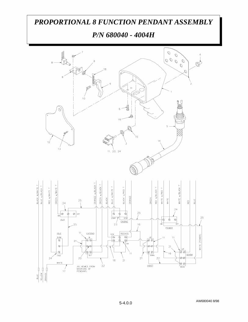
PROPORTIONAL 8 FUNCTION PENDANT ASSEMBLY
P/N 680040 - 4004H
AW680040 8/985-4.0.0

NOTES:1. Items 5 & 14 may be purchased as replacement Cable Assembly using P/N 380000.2. Items 6, 7, 8, 9, 10, 18, & 19 may be purchased as a replacement Potentiometer Kit using P/N380003.3. Items 1, 2, 12, & 13 may be purchased as a replacement Housing Kit using P/N 380002.4. Items 3, 4, 11, & 15 may be purchased as a replacement DPDT Switch Kit using P/N 380005.5. Items 3, 4, 15, & 24 may be purchased as a replacement On/Off Switch Kit using P/N 380001.6. Items 3, 4, 11, & 23 may be purchased as a replacement SPDT Switch Kit using P/N 380004.
PROPORTIONAL 8 FUNCTION PENDANT ASSEMBLY
P/N 680040 - 4004H
AW680040 8/98
CABLE TIE226
CONDUCTOR ASSEMBLY125
TOGGLE ON/OFF SWITCH324
TOGGLE SPDT SWITCH123
CONDUCTOR ASSEMBLY 3 1/8322
CONDUCTOR ASSEMBLY 2 1/8421
JUMPER420
PAN HD ST SCREW #6 x 3/8119
TRIGGER RETURN SPRING118
CONDUCTOR ASSEMBLY117
CONDUCTOR ASSEMBLY316
LOCK WASHER815
CABLE ASSEMBLY114
ST RD HD SCREW #6 x 3/4413
BACK PLATE112
TOGGLE DPDT SWITCH411
SOC HD SCREW #10 NF x 5/8110
TRIGGER19
POTENTIOMETER ASSEMBLY18
HEX LOCK NUT #10 NC27
SCREW #10 NC x 3/426
HUBBELL CONNECTOR CORD GRIP15
TOGGLE SWITCH BOOT84
NUT83
COVER PLATE DECAL 12
PENDANT HOUSING11
DESCRIPTIONQTYITEM
5-4.1.0

AW751140A 10/98
TROUBLESHOOTING HINTS751140-99917
INSTALLATION INSTRUCTIONS751140-99916
WIRING DIAGRAM 751140-99915
16 GA WHITE WIRE w/ BLACK TRACER x 15’80060315 FT4
RING TERMINAL #600010183
ISOLATOR MODULE ASSEMBLY751143-00112
12V DC SOLENOID w/ CONTROL MODULE75115911
DESCRIPTIONP/NQTYITEM
THROTTLE SOLENOID ASSEMBLY
P/N 751140
5-5.0.0

LOCATION
Follow these simple rules to properly locateyour throttle control kit:
1. Mount the solenoid off the engine but within46 inches of the throttle lever, to avoidengine vibration and high temperaturecomponents (more than 257 ºF [125 ºC]).
2. Mount control module out of the enginecompartment if possible. If not possible,mount the module as far away from hightemperature components as possible.Maximum temperature range is 185 ºF (85ºC).
3. Route the flexible cable away from hightemperature (220 ºF [105 ºC]) componentssuch as exhaust manifolds.
4. Avoid sharp bends in flexible cable. Bendsshould form a smooth arc (360º maximum)with a radius of 5 inches minimum.
CONTROLLING THE SOLENOIDTHROTTLE KIT
The throttle kit can be controlled remotely byapplying a low current 12 VDC signal to themodule “AUX” terminal.
Examples of activating signals are an aircompressor pressure switch or a crane “dumpvalve” coil.
MOUNTING PROCEDURES
Use the following procedure to mount yourthrottle controller:
1. Mount the solenoid and control moduleaccording to the recommendations in the“LOCATION” instructions
2. Electrically connect the solenoid to thecontrol module and power source accordingto the wiring diagram.
3. Mount the cable bracket and fasten the cablesheathe to the bracket using the collar nut sothe sheath does not turn during idleadjustment.
SET HIGH ENGINE IDLE SPEED NOTE:
Do not leave the aluminum adjustment nuttight against the solenoid body since thisdoes not allow the cable to float.
1. Make sure the jam nut is loose and turn thealuminum adjustment nut clockwise until thehigh engine idle speed is reached.
2. Tighten the jam nut.
3. Check the throttle speed controlleroperation by rechecking the “normal” engineidle speed with the solenoid deactivated andthe high engine idle speed with the solenoidactivated.
SYSTEM OPERATION
The control module allows the solenoid tooperate as a continuous duty device. When themodule is wired as recommended, applying 12VDC to the “AUX” terminal applies voltage tothe hold-in and pull-in coil of the solenoid.After 0.5 to 0.75 seconds, power isautomatically removed from the pull-in coil.Power will remain at the hold-in coil until the
AW751140A 10/98
THROTTLE CONTROL SOLENOID
INSTALLATION
5-5.1.0

12 VDC signal is removed from the “AUX”terminal.
WARNING!! To avoid control moduledamage, always disconnect the modulewhen you jump-start the vehicle withvoltages that exceed 32 VDC.
TROUBLESHOOTING HINTS
If solenoid will not engage, check thefollowing:
1. Check the stranded pull cable for damage(e.g., melted or crimped sheath)
2. Check the stranded pull cable for binding.
3. Check system voltage at the “+HOT” and“+AUX” terminals.
4. Check module terminals for proper voltageand operation. If the module does not meetthe specifications shown below, replace it.
5. Check solenoid resistance (remove wiresfrom module). If resistance is not withinspecifications listed below, replace the
A. White to Black - 0.17 ohms
B. Red to Black wire - 13 ohms
solenoid.
6. Make sure you have used the recommendedwire length and gage.
7. Be sure cable is not bent beyond guidelines.
8. Check for proper adjustments.
9. Contact Auto Crane Company if you areunable to resolve the problem.
AW751140A 10/98
THROTTLE CONTROL SOLENOID
INSTALLATION
5-5.2.0
CONTROL MODULE VOLTAGEMEASUREMENTS
Common for solenoidC BLK
12 VDC for 0.5 to 0.75 secondsafter signal at “AUX” terminal ispresent
B WHT
12 VDC when signal is present at“AUX” terminal
A RED
12 VDC required to activatesolenoid
+AUX
12 VDC at all times+HOT
Chassis GroundGND

751140 12/99
SPEED CONTROL KIT,
P/N 751140
5-5.3.0
NOTES:1. THIS DIAGRAM SHOWS SPEED CONTROL INSTALLTION WITH OR WITHOUT AN AIR COMPRESSOR. DISREGARD ISOLATOR BLOCK & PRESSURE SWITCH ON DIAGRAM IF NOT USING AN AIR COMPRESSOR.2. REMOVE METAL JUMPER CLIP FROM CONTROL MODULE IF SO EQUIPPED (S500-A5).3. THE WIRE SIZE AND LENGTH TO "AUX" TERMINAL IS NOT CRITICAL BECAUSE OF LOW CURRENT; 16-18 GAGE WIRE MAY BE USED.

AW480533 1/99
ENGINE START/STOP RELAY KIT
P/N 480533
BLUE 16 GA WIRE80059435’10
RED 16 GA WIRE80059317’9
BLACK 16 GA WIRE80059049’8
GREEN 16 GA WIRE8005956’7
5/16 TERMINAL RING 00050136
1/4 TERMINAL RING 00040235
FLANGED SPADE TERMINAL48049524
FEMALE SPADE LOCK CONNECTOR320357103
RELAY PLUG32036322
12V RELAY32035521
DESCRIPTIONP/NQTYITEM
5-5.4.0

AW480534 1/99
AUXILIARY RELAY KIT
P/N 480534
WHITE 16 GA WIRE80059225’9
RED 16 GA WIRE80059310’8
GREEN 16 GA WIRE80059538’7
5/16 TERMINAL RING 00050116
1/4 TERMINAL RING 00040215
#6 TERMINAL RING00010124
FEMALE SPADE LOCK CONNECTOR32035753
RELAY PLUG32036322
12V RELAY32035521
DESCRIPTIONP/NQTYITEM
5-5.4.1

AW404089 1/2000
HYDRAULIC ASSEMBLY
P/N 404089 - MODEL 4004H
6-1.0.0
PORT 1 PORT 2
View of Hydraulic Swivel from Bottom of Crane
CAUTION:Reversing tank and pressure hoses will damage pump.

AW404089 1/2000
HYDRAULIC ASSEMBLY
P/N 404089 - MODEL 4004H
6-1.1.0

AW404089 1/2000
HYDRAULIC ASSEMBLY
P/N 404089 - MODEL 4004H
HOSE ASSEMBLY x 13812210-0131 30
SWIVEL BRACKET4041121 29
COUNTERBALANCE CARTRIDGE4801881 28
HEX HD SCREW 3/8 NC x 1/2008401 1 27
FLAT WASHER 3/8021200 1 26
LOCK WASHER 3/80211004 25
CAPSCREW 3/8 NC x 3/4008400 3 24
HYDRAULIC SWIVEL320714 123
EXTRA LONG ADAPTER -6ORM/-6JICM404104222
45º ELBOW SWIVEL -6JIC3306471 21
TUBE ASSEMBLY EXTENSION4802121 20
TEE OR/JIC RUN 9/16-18241168119
ELBOW 3/8EXT/9/16JIC EXT2008921 18
45º ELBOW -6 OR/-6JIC4801953 17
90º ELBOW EXTRA LONG -10NPTM/-8JICM3720421 16
90º ELBOW -10ORM/-6JICM4901983 15
90º ELBOW -6 SWIVEL/-6JIC4801944 14
STRAIGHT LONG ADAPTER -6OR/-6JICM3730475 13
STRAIGHT ADAPTER -6ORM/-6JICM2008768 12
HOSE ASSEMBLY x 29812209-0292 11
HOSE ASSEMBLY x 13812209-0131 10
HOSE ASSEMBLY x 33812209-0332 9
HOSE ASSEMBLY x 36812209-0362 8
TUBE ASSEMBLY4041091 7
TUBE ASSEMBLY4041081 6
MOTOR HOIST (320741)REF- 5
MOTOR ROTATION (320740)REF- 4
CYLINDER EXTENSION (360152)REF- 3
CYLINDER BOOM (404005)REF- 2
HYDRAULIC MANIFOLD ASSEMBLY (320725) REF- 1
DESCRIPTIONP/NQTYITEM
6-1.2.0

IMPORTANTCrane boom must be supportedand pump system disengagedduring the removal and installa-tion of the pressure gage portplug, pressure gage, pressureswitch and counterbalance valve.
Valve SettingTo set counterbalance valve:
1. With boom supported, remove -6 ORP plugon cylinder block next to valve and install apressure gauge; 2500 psi capacity minimum.
2. Boom up until boom cylinder is fullyelevated.
3. Boom down in small increments whilereading pressure gauge.
4. Loosen the 9/16” nut on end of valve, adjust5/32” Allen screw and then retighten nut.Repeat procedure until pressure reading is aconstant 900 psi. If valve is not set andboom reaches the full down position, boomup and keep trying.
5. Support boom, remove gauge and replaceplug when adjustment is complete.
4HHYD 8/98
HYDRAULICS
4004H SERIES
6-2.0.0
CAUTION:IF COUNTERBALANCE VALVE IS REPLACED, THE CORRECT PRESSURESETTING MUST BE MADE BEFORE CRANE IS IN SAFE WORKINGCONDITION.

1 CRANE FAILS TO OPERATE (ALLFUNCTIONS)
A. Make sure power switch is set to the "on"position on the pendant.
B. Check power to crane by checking for truckvoltage at terminal #11 on terminal strip.white harness wire.
1. If truck voltage, then go to C.
2. If not check continuity back to battery.
C. If there is power at terminal #11 and nofunctions are operable, find proportionalvalve on the right side of the hydraulicassembly and screw the manual overrideclockwise to provide flow to manifold.operate a function with the manual override(push or pull).
1. If that function operates properly, thenthe problem is in the control circuitpower wire (pendant or receptacle).Go to D.
2. If that function does not operateproperly, go to E.
D. Electrical problem solutions: pick a specificfunction and check voltage at the terminalstrip by energizing that function using thependant switch.
1. If voltage is present, then check theground circuit for continuity.
2. If voltage is not present, then checkpendant and harness wiring for a break inthe white power wire or the coloredfunction wire.
E. Hydraulic problem solutions:
1. Make sure the PTO and/or the flowcontrol device(s) are engaged andoperable. Noise in pump system or exces-sive heat in the hydraulic system mayindicate a worn or broken pump.
2. Check the compensator valve forcontamination.
2 HOIST UP, BOOM DOWN, AND EXTEND(OUT) DON'T OPERATE (ALL OTHERFUNCTIONS DO OPERATE). THESETHREE FUNCTIONS ARE TIED INTOTHE ANTI-TWO BLOCK AND CRANEOVERLOAD SENSOR SYSTEMS. THECRANE IS SHUT DOWN WHEN THESENSORS OPEN THE GROUND CIRCUITFROM THE FUNCTIONS.
A. Unplug the anti-two-block system and recon-nect din connectors to allow overload systemto function (as shown in the manual).
1. If the three functions work, go to B.
2. If the three functions do not work, go to C.
B. With anti-two-block reconnected, check anti-two-block bail and switch at end of boom toverify they move freely. Switch should makeaudible click when operated. Try operatingcrane while pulling cord out of cord reel tocheck for possible bad spots in cord reel sliprings. Check cord for breaks. A ohmmetercan be used on the two din connectors to testthis system while it is unplugged. The systemis normally open.
C. Check load sensor pressure switch byunplugging the din connector and checkingfor a closed circuit.
1. If circuit is closed and boom is unloaded,replace switch and reconnect anti-two-block circuit.
CAUTION: BE SURE BOOM ISSUPPORTED BEFORE REMOVINGSWITCH OR BOOM WILL FALL.
2. If circuit is open, go to D.
4HTRBL 8/98
7-3.2.0
4004H TROUBLESHOOTING GUIDE
6-3.0.0

D. Locate timing relay box on back of crane andopen lid. Disconnect yellow wire on terminal#1 of the time delay relay.
1. If the three functions do not work, checkthe ground for overload system throughthe relay. (The relay may be operated bytouching the yellow wire to any ground.)
2. If three functions work, clean terminals#6 and #7 on time delay relay, reconnectyellow wire to #1 terminal and retry thethree functions.
i. If the three functions still do notwork, replace the time delay relay.
ii. If the three functions work, spray theterminals with a protective coatingand keep them clean.
3. The time delay relay may be operated byremoving the connectors from terminals#6 and #7 and shorting the two terminalswith a jumper. The interval betweenmake and brake is approximately ¾second.
CAUTION: CONNECTING THEPOWER TERMINAL #3 TO TERMI-NAL #6 MAY CAUSE RELAYFAILURE.
3 SINGLE HYDRAULIC FUNCTION DOESNOT WORK.
A. With trigger pulled, operate the functionusing the manual override.
1. If it works, check power and groundgoing to coil at weather pack connector.
i. Verify ground circuit.
ii. Verify function power circuit.
2. If it does not work, then remove valve,clean and inspect it.
3. If it still does not work, then check cylin-der or motor and connecting hoses forobstructions or failure.
B. Test the proportional activation system alsoby operating the proportional manualoverride screw instead of the trigger on thependant. Be sure to restore the override tothe full out position before using the crane.
C. If boom retract or boom down functionsdon't work, then check for low hydraulicpressure at pump. These two functions havethe highest pressure requirements for anunloaded crane because they must overcomethe pressure settings of the counter balancevalves.
D. If hydraulic functions are more intermittentwhen cylinders are extended, then checkhydraulic fluid level.
E. Boom locks up and won't come down whenfully raised-this is caused by having the pumprelief pressure higher than the pressure thatcauses the overload system to activate. Setrelief pressure to the correct setting of 2200psi. Unlock boom by using the manualoverride of the boom down function. Ifpressure is correct and problem continues,then replace overload pressure switch.
4HTRBL 8/98
7-3.2.0
4004H TROUBLESHOOTING GUIDE
6-3.1.0

NOTES:
1. Pump speed - 800 RPM for 4004H and 950 RPM for 5005H.
2. To order HYDRAULIC PUMP ASSEMBLY use P/N 360030 - which consists ofHYDRAULIC PUMP (P/N 360029), 3/4-14NPT/1-5/16-12 JIC ADAPTER (P/N 360055)SUCTION AND 3/4-14 NPT/ 1 1/16-12 JIC (750399) PRESSURE.
3. For SEAL KIT use P/N 480018-001.
4. For SERVICE KIT use P/N 480018-002.
AW360029 10/98
HYDRAULIC DIRECT MOUNT PUMP
P/N 360029 - 4004H SERIES
6-4.0.0
Adapter: SAE “A” 2 bolt flange (direct mount only).Shaft: Straight shaft key 3/4 dia. x 2 3/4 long. 3/16 sq. key x 1 5/8 long.

AW404121 8/98
LOAD CHART 10-16-20
P/N 404121 - 4004H SERIES
9-1.0.0

AW404120 7/98
LOAD CHART 10-16
P/N 404120 - 4004H SERIES
9-2.0.0