Embed Size (px)
Citation preview
Autoclavable & UV r e s i s t a n t
Digital micro pipette for liquid handling
User’s Manual
In Vitro Medical Diagnostic Devices (98/79/EC)
Annex III self-declared
ISO 8655 STANDARD
CERTIFIED ISO9001
● Thank you very much for purchasing Nichipet Premium.
● Please read this manual carefully before using.
Always Pursuing Originality
Since 1944
- 1 -
Autoclavable & UV r e s i s t a n t
Digital micro pipette for liquid handling
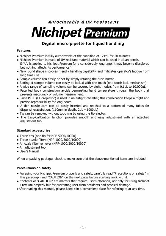
Features
● Nichipet Premium is fully autoclavable at the condition of 121°C for 20 minutes. ● Nichipet Premium is made of UV resistant material which can be used in clean bench.
(If UV is applied to Nichipet Premium for a considerably long time, it may become discolored but nothing affects its performance.)
● New round shape improves friendly handling capability, and mitigates operator’s fatigue from long time use.
● Sample volume can easily be set by simply rotating the push button. ● Setting of sample volume can easily be locked with one touch (one-touch lock mechanism). ● A wide range of sampling volume can be covered by eight models from 0.1uL to 10,000uL. ● Patented body construction avoids permeating hand temperature through the body that
prevents inaccuracy of volume measurement. ● Since PTFE (Fluoroplastic) is used in an airtight chamber, this combination keeps airtight and
precise reproducibility for long hours. ● A thin nozzle corn can be easily inserted and reached to a bottom of many tubes for
dispensing/aspiration. (110mm in depth, 2uL – 1000uL) ● Tip can be removed without touching by using the tip ejector. ● The Easy-Calibration function provides smooth and easy adjustment with an attached
adjustment tool.
Standard accessories
● Three tips (one tip for NPP-5000/10000) ● Three nozzle filters (NPP-1000/5000/10000) ● A nozzle filter remover (NPP-1000/5000/10000) ● An adjustment tool ● User’s Manual
When unpacking package, check to make sure that the above-mentioned items are included.
Precautions on safety
● For using your Nichipet Premium properly and safely, carefully read “Precautions on safety” in this paragraph and “CAUTION” on the next page before starting work with it.
● Contents of “CAUTION” are matters that require user’s attention, not only for using Nichipet Premium properly but for preventing user from accidents and physical damage.
●After reading this manual, please keep it in a convenient place for referring to at any time.
- 2 -
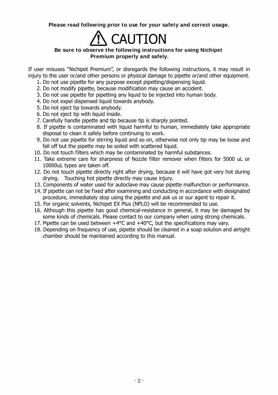
Please read following prior to use for your safety and correct usage.
CAUTION Be sure to observe the following instructions for using Nichipet
Premium properly and safely. If user misuses “Nichipet Premium”, or disregards the following instructions, it may result in injury to the user or/and other persons or physical damage to pipette or/and other equipment.
1. Do not use pipette for any purpose except pipetting/dispensing liquid. 2. Do not modify pipette, because modification may cause an accident. 3. Do not use pipette for pipetting any liquid to be injected into human body. 4. Do not expel dispensed liquid towards anybody. 5. Do not eject tip towards anybody. 6. Do not eject tip with liquid inside. 7. Carefully handle pipette and tip because tip is sharply pointed. 8. If pipette is contaminated with liquid harmful to human, immediately take appropriate
disposal to clean it safely before continuing to work. 9. Do not use pipette for stirring liquid and so on, otherwise not only tip may be loose and
fall off but the pipette may be soiled with scattered liquid. 10. Do not touch filters which may be contaminated by harmful substances. 11. Take extreme care for sharpness of Nozzle filter remover when filters for 5000 uL or
10000uL types are taken off. 12. Do not touch pipette directly right after drying, because it will have got very hot during
drying. Touching hot pipette directly may cause injury. 13. Components of water used for autoclave may cause pipette malfunction or performance. 14. If pipette can not be fixed after examining and conducting in accordance with designated
procedure, immediately stop using the pipette and ask us or our agent to repair it. 15. For organic solvents, Nichipet EX Plus (NPLO) will be recommended to use. 16. Although this pipette has good chemical-resistance in general, it may be damaged by
some kinds of chemicals. Please contact to our company when using strong chemicals. 17. Pipette can be used between +4°C and +40°C, but the specifications may vary. 18. Depending on frequency of use, pipette should be cleaned in a soap solution and airtight
chamber should be maintained according to this manual.
- 3 -
Note
Users are required to strictly observe the followings in order for the pipette to keep its excellent precision, reproducibility and original
performance for a long time.
1. Do not expose pipette directly to the sun when working with it or for 2 hours before starting work, otherwise the pipette may lose accuracy. Avoid working with pipettes in a humid and hot place.
2. Just before starting work with pipette, avoid touching tip and nozzle cylinder as far as conditions are allowed. If nozzle cylinder is warmed by your hand, accuracy may vary.
3. For pipetting, follow the forward method (the way explained in this manual). If it is performed in a different way, it may result in inaccurate pipetting.
4. Operate push button very gently. If it is quickly released, it may result not only inaccurate pipetting but also deteriorated the pipette because sample liquid may be permeated into the main body. To prevent the pipette from malfunction, inaccuracy and contamination, a filter is attached to models NPP-1000, -5000, and -10000. (A filter is supplied at time of purchase.)
5. Do not reuse tip that has been used once, and carefully dispose used tip. If tip is used repeatedly, it may cause inaccurate and impure pipetting and cross contamination (*) among samples.
* .For example, if previous sample liquid is left inside tip, it is mixed with new sample liquid and the new sample is contaminated by the previous one. Therefore, pipetting of the next sample results wrong. This phenomenon is called mutual contamination of samples.
6. Do not hold pipette horizontally or upside down when there is liquid inside tip, otherwise the liquid gets into the main body and the pipette may be contaminated.
7. When autoclaving, do not pile pipettes on others in the autoclave or lean pipettes with a nozzle top facing down so that self-load is applied on the nozzle. This pipette is made of an autoclave compatible material, but because of high temperature in the sterilizer, there is a risk that parts subject to load will be deformed.
8. After autoclaving and drying pipette, leave it until it gets completely cool before using again. If the pipette is used when warm, the accuracy may not come up to the standard level.
9. After autoclaving and drying pipette, assemble the pipette after it is completely cooled, if it is assembled when it is still hot, it may cause deterioration in the pipette such as breakage of the screw threads.
10. When rotating push button, do not exceed the specified sample volume limit, otherwise pipette may be damaged or deteriorated.
11. Do not perform pipetting with less liquid than set volume. If the quantity of liquid is less than the set volume, it may cause the liquid to scatter into the main body and the pipette may deteriorate in quality.
- 4 -
Contents
Operating procedure ······················································· 5
Disassembling/Reassembling the airtight chamber ··················· 9
Autoclaving/Drying the pipette ··········································· 18
Specification ································································· 19
Volume setting procedure ················································· 20
Troubleshooting ····························································· 22
Parts list······································································· 24
- 5 -
NPP-2
2μl 10μl 20μl 100μl 200μl 1000μl 5000μl 10000μl(0.002) (0.01) (0.02) (0.1) (0.2) (1.0) (10.0) (10.0)
NPP-10 NPP-20 NPP-100 NPP-200 NPP-1000 NPP-5000 NPP-10000
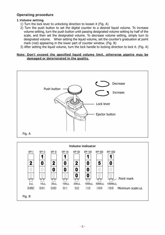
Operating procedure 1.Volume setting
1) Turn the lock lever to unlocking direction to loosen it (Fig. A) 2) Turn the push button to set the digital counter to a desired liquid volume. To increase
volume setting, turn the push button until passing designated volume setting by half of the scale, and then set the designated volume. To decrease volume setting, simply turn to designated volume. When setting the liquid volume, set the counter’s graduation at point mark (red) appearing in the lower part of counter window. (Fig. B)
3) After setting the liquid volume, turn the lock handle to locking direction to lock it. (Fig. A)
Note: Don’t exceed the specified liquid volume limit, otherwise pipette may be damaged or deteriorated in the quality.
Decrease
IncreasePush button
Lock lever
Ejector button
Fig. A
Fig. B
Point mark
Minimum scale:uL
Volume indicator
2uL 10uL 20uL 100uL 200uL 1000uL 5000uL 10000uL
- 6 -
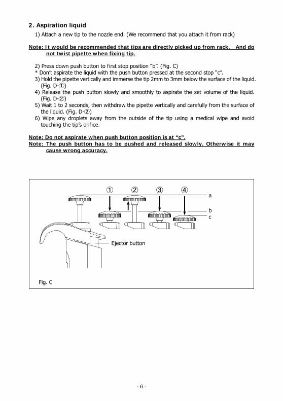
2. Aspiration liquid 1) Attach a new tip to the nozzle end. (We recommend that you attach it from rack)
Note: It would be recommended that tips are directly picked up from rack. And do not twist pipette when fixing tip.
2) Press down push button to first stop position “b”. (Fig. C) * Don’t aspirate the liquid with the push button pressed at the second stop “c”. 3) Hold the pipette vertically and immerse the tip 2mm to 3mm below the surface of the liquid.
(Fig. D- )① 4) Release the push button slowly and smoothly to aspirate the set volume of the liquid.
(Fig. D- )② 5) Wait 1 to 2 seconds, then withdraw the pipette vertically and carefully from the surface of
the liquid. (Fig. D- )② 6) Wipe any droplets away from the outside of the tip using a medical wipe and avoid
touching the tip’s orifice.
Note: Do not aspirate when push button position is at “c”. Note: The push button has to be pushed and released slowly. Otherwise it may
cause wrong accuracy.
① ② ③ ④
Fig. C
a
bc
Ejector button
- 7 -
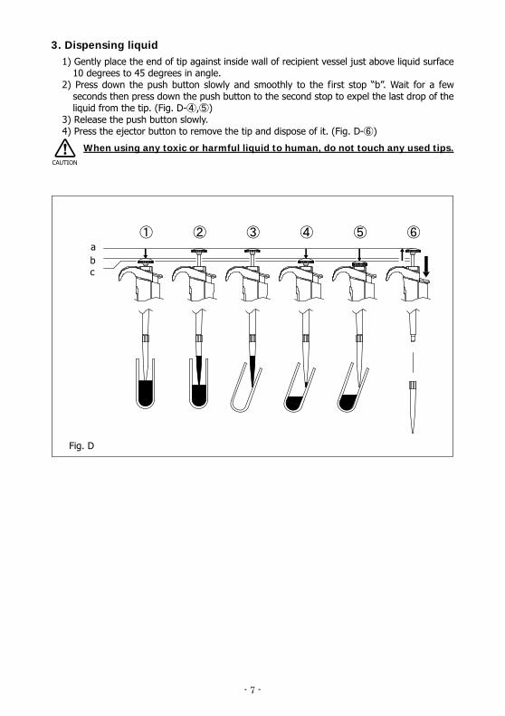
3. Dispensing liquid 1) Gently place the end of tip against inside wall of recipient vessel just above liquid surface
10 degrees to 45 degrees in angle. 2) Press down the push button slowly and smoothly to the first stop “b”. Wait for a few
seconds then press down the push button to the second stop to expel the last drop of the liquid from the tip. (Fig. D- , )④ ⑤
3) Release the push button slowly. 4) Press the ejector button to remove the tip and dispose of it. (Fig. D- )⑥
When using any toxic or harmful liquid to human, do not touch any used tips.
① ② ③ ④ ⑤ ⑥
Fig. D
b c
a
CAUTION
- 8 -
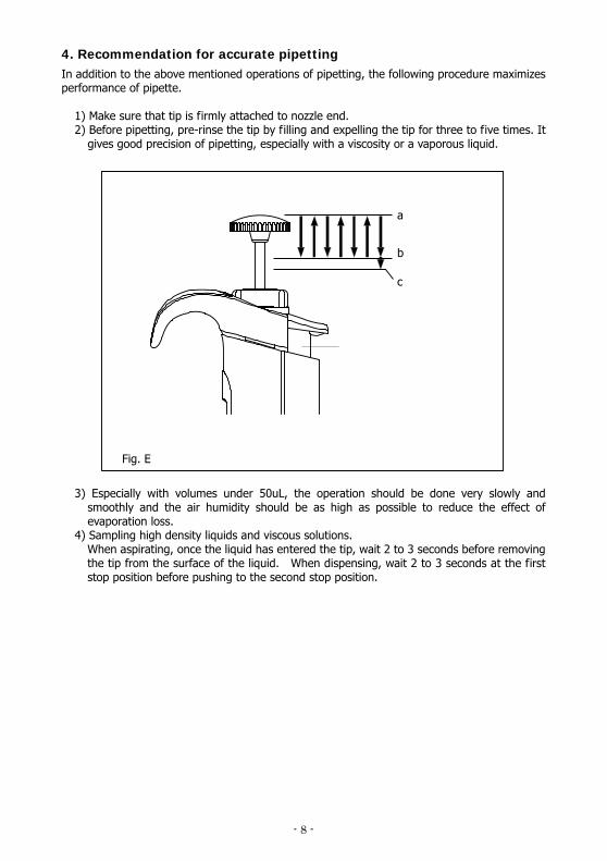
4. Recommendation for accurate pipetting In addition to the above mentioned operations of pipetting, the following procedure maximizes performance of pipette.
1) Make sure that tip is firmly attached to nozzle end. 2) Before pipetting, pre-rinse the tip by filling and expelling the tip for three to five times. It
gives good precision of pipetting, especially with a viscosity or a vaporous liquid. 3) Especially with volumes under 50uL, the operation should be done very slowly and
smoothly and the air humidity should be as high as possible to reduce the effect of evaporation loss.
4) Sampling high density liquids and viscous solutions. When aspirating, once the liquid has entered the tip, wait 2 to 3 seconds before removing the tip from the surface of the liquid. When dispensing, wait 2 to 3 seconds at the first stop position before pushing to the second stop position.
Fig. E
a
b
c
- 9 -
Disassembling/Reassembling the airtight chamber If such symptoms as mentioned in “Troubleshooting” (page 21) occur, disassemble and inspect pipette according to the following procedures.
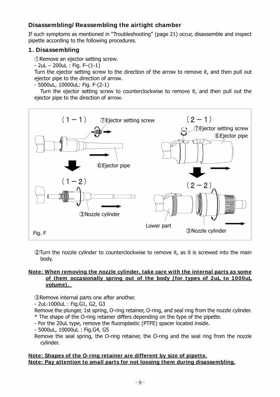
1. Disassembling ①Remove an ejector setting screw. - 2uL – 200uL : Fig. F–(1-1) Turn the ejector setting screw to the direction of the arrow to remove it, and then pull out ejector pipe to the direction of arrow. - 5000uL, 10000uL: Fig. F-(2-1)
Turn the ejector setting screw to counterclockwise to remove it, and then pull out the ejector pipe to the direction of arrow.
Turn the nozzle ② cylinder to counterclockwise to remove it, as it is screwed into the main body.
Note: When removing the nozzle cylinder, take care with the internal parts as some
of them occasionally spring out of the body (for types of 2uL to 1000uL volume).
Remove internal parts one after another. ③
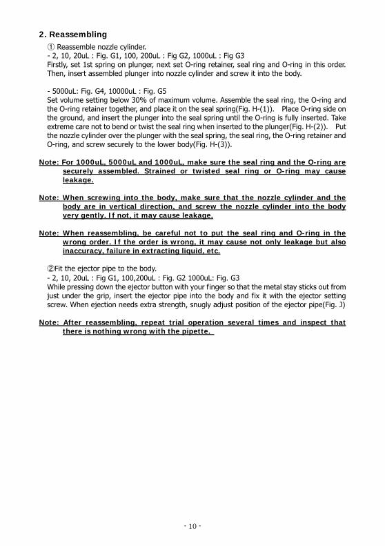
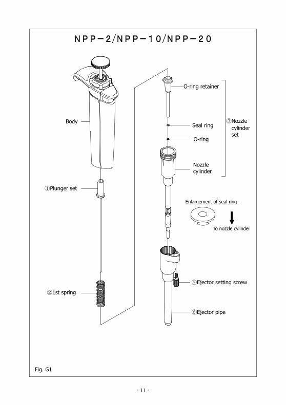
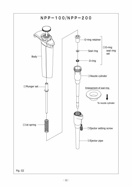
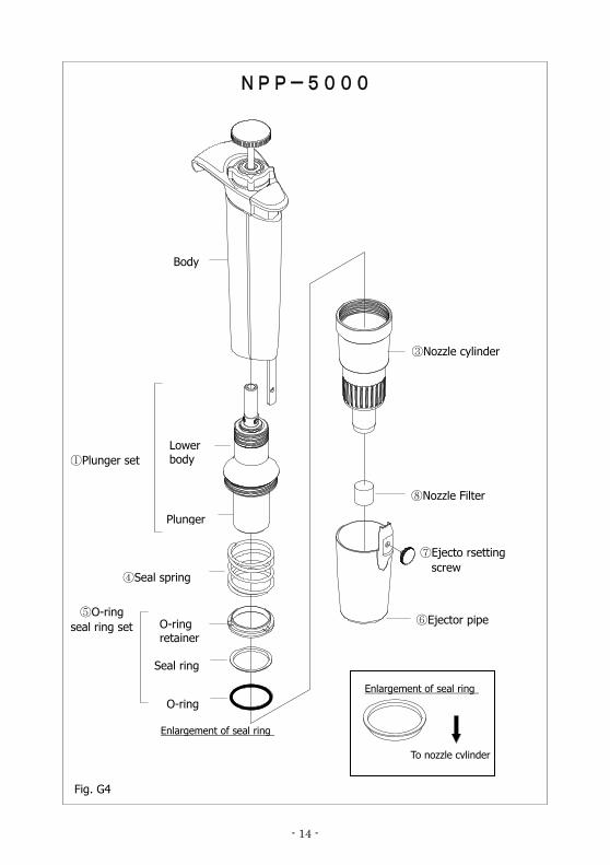
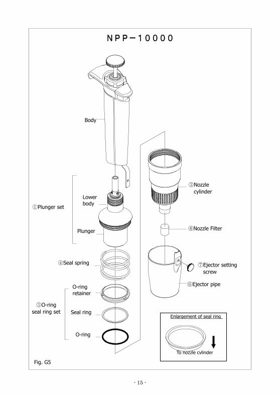
- 2uL-1000uL : Fig.G1, G2, G3 Remove the plunger, 1st spring, O-ring retainer, O-ring, and seal ring from the nozzle cylinder. * The shape of the O-ring retainer differs depending on the type of the pipette. - For the 20uL type, remove the fluoroplastic (PTFE) spacer located inside. - 5000uL, 10000uL : Fig.G4, G5 Remove the seal spring, the O-ring retainer, the O-ring and the seal ring from the nozzle
cylinder.
Note: Shapes of the O-ring retainer are different by size of pipette. Note: Pay attention to small parts for not loosing them during disassembling.
Fig. F
(2-2)
(2-1)
(1-2)
(1-1)
⑥Ejector pipe
⑥Ejector pipe
③Nozzle cylinder
⑦Ejector setting screw
⑦Ejector setting screw
③Nozzle cylinder
Lower part
- 10 -
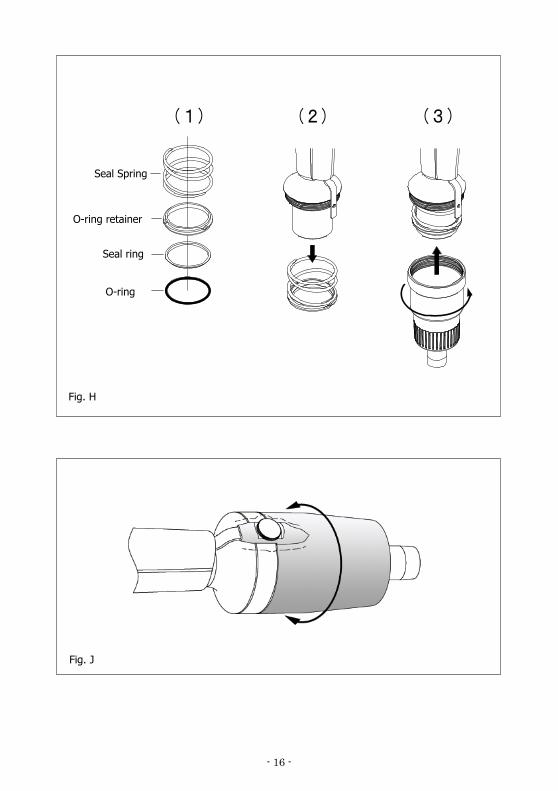
2. Reassembling ① Reassemble nozzle cylinder. - 2, 10, 20uL : Fig. G1, 100, 200uL : Fig G2, 1000uL : Fig G3 Firstly, set 1st spring on plunger, next set O-ring retainer, seal ring and O-ring in this order. Then, insert assembled plunger into nozzle cylinder and screw it into the body. - 5000uL: Fig. G4, 10000uL : Fig. G5 Set volume setting below 30% of maximum volume. Assemble the seal ring, the O-ring and the O-ring retainer together, and place it on the seal spring(Fig. H-(1)). Place O-ring side on the ground, and insert the plunger into the seal spring until the O-ring is fully inserted. Take extreme care not to bend or twist the seal ring when inserted to the plunger(Fig. H-(2)). Put the nozzle cylinder over the plunger with the seal spring, the seal ring, the O-ring retainer and O-ring, and screw securely to the lower body(Fig. H-(3)).
Note: For 1000uL, 5000uL and 1000uL, make sure the seal ring and the O-ring are
securely assembled. Strained or twisted seal ring or O-ring may cause leakage.
Note: When screwing into the body, make sure that the nozzle cylinder and the
body are in vertical direction, and screw the nozzle cylinder into the body very gently. If not, it may cause leakage.
Note: When reassembling, be careful not to put the seal ring and O-ring in the
wrong order. If the order is wrong, it may cause not only leakage but also inaccuracy, failure in extracting liquid, etc.
②Fit the ejector pipe to the body. - 2, 10, 20uL : Fig G1, 100,200uL : Fig. G2 1000uL: Fig. G3 While pressing down the ejector button with your finger so that the metal stay sticks out from just under the grip, insert the ejector pipe into the body and fix it with the ejector setting screw. When ejection needs extra strength, snugly adjust position of the ejector pipe(Fig. J)
Note: After reassembling, repeat trial operation several times and inspect that
there is nothing wrong with the pipette.
- 11 -
Body
①Plunger set
②1st spring
O-ring retainer
Seal ring
O-ring
Nozzle cylinder
③Nozzle cylinder set
Enlargement of seal ring
To nozzle cylinder
⑦Ejector setting screw
⑥Ejector pipe
Fig. G1
NPP-2/NPP-10/NPP-20
- 12 -
ボディ
①プランジャセット
O-リング押さえ
シールリング
③ノズルシリンダ
シールリング向き
O-リング
⑥エジェクタパイプ
⑦エジェクタ止めネジセット
ノズルシリンダ
先端側
②一段バネ
⑤Oリング・
シールリング
セット
Fig. G2
O-ring retainer
Body
⑥Ejector pipe
②1st spring ⑦Ejector setting screw
①Plunger set
To nozzle cylinder
Enlargement of seal ring
③Nozzle cylinder
O-ring
Seal ring ⑤O-ring
seal ring set
NPP-100/NPP-200
- 13 -
Body
①Plunger set
②1st spring
O-ring retainer
Seal ring
O-ring
③Nozzle cylinder
⑤O-ring seal ring set
Enlargement of seal ring
To nozzle cylinder
⑦Ejector setting screw
⑥Ejector pipe
Fig. G3
⑧Nozzle Filter
NPP-1000
- 14 -
Lower body
O-ring retainer
Seal ring
Plunger
NPP-5000
Body
①Plunger set
④Seal spring
O-ring
⑤O-ring seal ring set
Enlargement of seal ring
To nozzle cylinder
⑦Ejecto rsetting screw
⑥Ejector pipe
Fig. G4
⑧Nozzle Filter
③Nozzle cylinder
Enlargement of seal ring
- 15 -
ボディ
Lower body
Plunger
Body
①Plunger set
Seal ring
O-ring
⑤O-ring seal ring set
Enlargement of seal ring
To nozzle cylinder
⑦Ejector setting screw
⑥Ejector pipe
Fig. G5
③Nozzle cylinder
NPP-10000
⑧Nozzle Filter
O-ring retainer
④Seal spring
- 16 -
(3)(1) (2)
O-ring retainer
Seal ring
O-ring
Fig. H
Seal Spring
Fig. J
- 17 -
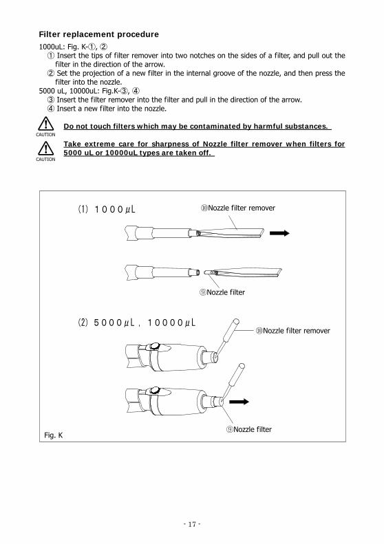
Filter replacement procedure 1000uL: Fig. K- , ① ②
Insert ① the tips of filter remover into two notches on the sides of a filter, and pull out the filter in the direction of the arrow. Set the projection of a new filter in the inter② nal groove of the nozzle, and then press the filter into the nozzle.
5000 uL, 10000uL: Fig.K- , ③ ④ Insert the filter remover into the filter and pull in the direction of the arrow. ③ Insert a new filter into the nozzle. ④
Do not touch filters which may be contaminated by harmful substances.
Take extreme care for sharpness of Nozzle filter remover when filters for 5000 uL or 10000uL types are taken off.
(1)1000μL
(2)5000μL ,10000μL
Fig. K
CAUTION
CAUTION
⑩Nozzle filter remover
⑨Nozzle filter
⑨Nozzle filter
⑩Nozzle filter remover
- 18 -
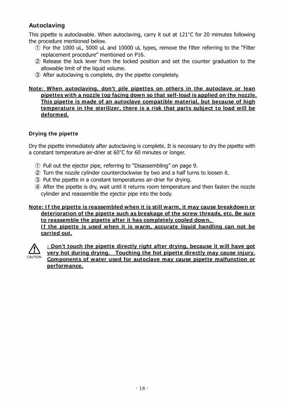
Autoclaving This pipette is autoclavable. When autoclaving, carry it out at 121°C for 20 mimutes following the procedure mentioned below.
① For the 1000 uL, 5000 uL and 10000 uL types, remove the filter referring to the “Filter replacement procedure” mentioned on P16.
② Release the lock lever from the locked position and set the counter graduation to the allowable limit of the liquid volume.
③ After autoclaving is complete, dry the pipette completely. Note: When autoclaving, don’t pile pipettes on others in the autoclave or lean
pipettes with a nozzle top facing down so that self-load is applied on the nozzle. This pipette is made of an autoclave compatible material, but because of high temperature in the sterilizer, there is a risk that parts subject to load will be deformed.
Drying the pipette
Dry the pipette immediately after autoclaving is complete. It is necessary to dry the pipette with a constant temperature air-drier at 60°C for 60 minutes or longer.
① Pull out the ejector pipe, referring to “Disassembling” on page 9. ② Turn the nozzle cylinder counterclockwise by two and a half turns to loosen it. ③ Put the pipette in a constant temperatures air-drier for drying. ④ After the pipette is dry, wait until it returns room temperature and then fasten the nozzle
cylinder and reassemble the ejector pipe into the body. Note: If the pipette is reassembled when it is still warm, it may cause breakdown or
deterioration of the pipette such as breakage of the screw threads, etc. Be sure to reassemble the pipette after it has completely cooled down. If the pipette is used when it is warm, accurate liquid handling can not be carried out.
: Don’t touch the pipette directly right after drying, because it will have got very hot during drying. Touching the hot pipette directly may cause injury. Components of water used for autoclave may cause pipette malfunction or performance.
CAUTION
- 19 -
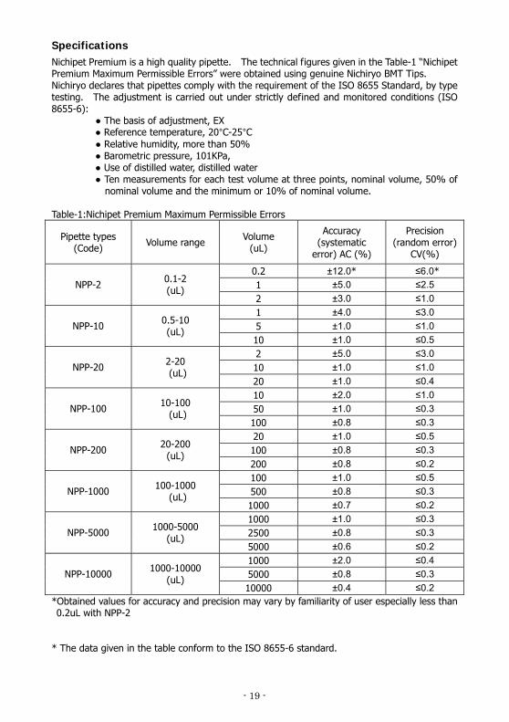
Specifications Nichipet Premium is a high quality pipette. The technical figures given in the Table-1 “Nichipet Premium Maximum Permissible Errors” were obtained using genuine Nichiryo BMT Tips. Nichiryo declares that pipettes comply with the requirement of the ISO 8655 Standard, by type testing. The adjustment is carried out under strictly defined and monitored conditions (ISO 8655-6):
● The basis of adjustment, EX ● Reference temperature, 20°C-25°C ● Relative humidity, more than 50% ● Barometric pressure, 101KPa, ● Use of distilled water, distilled water ● Ten measurements for each test volume at three points, nominal volume, 50% of
nominal volume and the minimum or 10% of nominal volume. Table-1:Nichipet Premium Maximum Permissible Errors
Pipette types (Code) Volume range Volume
(uL)
Accuracy (systematic
error) AC (%)
Precision (random error)
CV(%)
0.2 ±12.0* ≤6.0* 1 ±5.0 ≤2.5 NPP-2 0.1-2
(uL) 2 ±3.0 ≤1.0 1 ±4.0 ≤3.0 5 ±1.0 ≤1.0 NPP-10 0.5-10
(uL) 10 ±1.0 ≤0.5 2 ±5.0 ≤3.0 10 ±1.0 ≤1.0 NPP-20 2-20
(uL) 20 ±1.0 ≤0.4 10 ±2.0 ≤1.0 50 ±1.0 ≤0.3 NPP-100 10-100
(uL) 100 ±0.8 ≤0.3 20 ±1.0 ≤0.5 100 ±0.8 ≤0.3 NPP-200 20-200
(uL) 200 ±0.8 ≤0.2 100 ±1.0 ≤0.5 500 ±0.8 ≤0.3 NPP-1000 100-1000
(uL) 1000 ±0.7 ≤0.2 1000 ±1.0 ≤0.3 2500 ±0.8 ≤0.3 NPP-5000 1000-5000
(uL) 5000 ±0.6 ≤0.2 1000 ±2.0 ≤0.4 5000 ±0.8 ≤0.3 NPP-10000 1000-10000
(uL) 10000 ±0.4 ≤0.2
*Obtained values for accuracy and precision may vary by familiarity of user especially less than 0.2uL with NPP-2
* The data given in the table conform to the ISO 8655-6 standard.
- 20 -
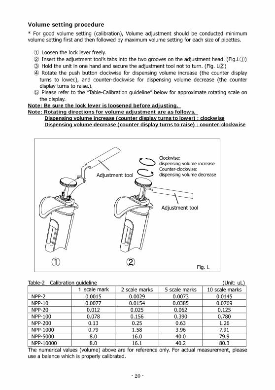
Volume setting procedure * For good volume setting (calibration), Volume adjustment should be conducted minimum volume setting first and then followed by maximum volume setting for each size of pipettes.
① Loosen the lock lever freely. ② Insert the adjustment tool’s tabs into the two grooves on the adjustment head. (Fig.L①) ③ Hold the unit in one hand and secure the adjustment tool not to turn. (Fig. L②) ④ Rotate the push button clockwise for dispensing volume increase (the counter display
turns to lower.), and counter-clockwise for dispensing volume decrease (the counter display turns to raise.).
⑤ Please refer to the “Table-Calibration guideline” below for approximate rotating scale on the display.
Note: Be sure the lock lever is loosened before adjusting. Note: Rotating directions for volume adjustment are as follows,
Dispensing volume increase (counter display turns to lower) : clockwise Dispensing volume decrease (counter display turns to raise) : counter-clockwise
Table-2 Calibration guideline (Unit: uL)
1 scale mark 2 scale marks 5 scale marks 10 scale marksNPP-2 0.0015 0.0029 0.0073 0.0145 NPP-10 0.0077 0.0154 0.0385 0.0769 NPP-20 0.012 0.025 0.062 0.125 NPP-100 0.078 0.156 0.390 0.780 NPP-200 0.13 0.25 0.63 1.26 NPP-1000 0.79 1.58 3.96 7.91 NPP-5000 8.0 16.0 40.0 79.9 NPP-10000 8.0 16.1 40.2 80.3
The numerical values (volume) above are for reference only. For actual measurement, please use a balance which is properly calibrated.
① ②Fig. L
Adjustment tool
Adjustment tool
Clockwise: dispensing volume increase Counter-clockwise: dispensing volume decrease
- 21 -
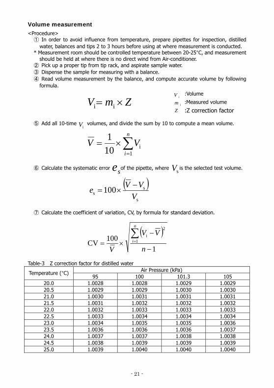
Volume measurement <Procedure>
① In order to avoid influence from temperature, prepare pipettes for inspection, distilled water, balances and tips 2 to 3 hours before using at where measurement is conducted.
* Measurement room should be controlled temperature between 20-25°C, and measurement should be held at where there is no direct wind from Air-conditioner.
② Pick up a proper tip from tip rack, and aspirate sample water. ③ Dispense the sample for measuring with a balance. ④ Read volume measurement by the balance, and compute accurate volume by following
formula.
⑤ Add all 10-time volumes, and divide the sum by 10 to compute a mean volume. ⑥ Calculate the systematic error of the pipette, where is the selected test volume. ⑦ Calculate the coefficient of variation, CV, by formula for standard deviation.
Table-3 Z correction factor for distilled water
Air Pressure (kPa) Temperature (°C) 95 100 101.3 105
20.0 1.0028 1.0028 1.0029 1.0029 20.5 1.0029 1.0029 1.0030 1.0030 21.0 1.0030 1.0031 1.0031 1.0031 21.5 1.0031 1.0032 1.0032 1.0032 22.0 1.0032 1.0033 1.0033 1.0033 22.5 1.0033 1.0034 1.0034 1.0034 23.0 1.0034 1.0035 1.0035 1.0036 23.5 1.0036 1.0036 1.0036 1.0037 24.0 1.0037 1.0037 1.0038 1.0038 24.5 1.0038 1.0039 1.0039 1.0039 25.0 1.0039 1.0040 1.0040 1.0040
ZmV ×= ii
∑=
×=n
iVV
1i10
1iV
( )s
ss 100
VVVe −
×=
se sV
( )1
100CV 1
2i
−
−×=∑=
n
VV
V
n
i
:Volume
ZmV
i
i
:Measured volume
:Z correction factor
- 22 -
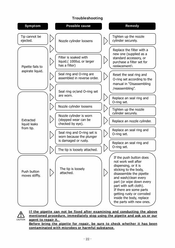
Extracted liquid leaks from tip.
Symptom Possible cause Remedy
Tip cannot be ejected.
Pipette fails to aspirate liquid.
Nozzle cylinder loosens
Tighten up the nozzle cylinder securely.
Filter is soaked with liquid.( 1000uL or larger has a filter)
Seal ring and O-ring are assembled in reverse order.
Seal ring or/and O-ring set are worn.
Replace the filter with a new one (supplied as a standard accessory, or purchase a filter set for replacement).
Reset the seal ring and O-ring set according to the manual in “Disassembling/reassembling”.
Replace an seal ring and O-ring set.
Nozzle cylinder loosens Tighten up the nozzle cylinder securely.
Nozzle cylinder is worn (stepped wear can be checked by eye).
Replace an nozzle cylinder.
Seal ring and O-ring set is worn because the plunger is damaged or rusty.
Replace an seal ring and O-ring set.
The tip is loosely attached.
Push button moves stiffly.
The tip is loosely attached.
Replace an seal ring and O-ring set.
If the push button does not work well after dispensing, or it is sticking to the body, disassemble the pipette and wash/clean every part (or wipe down every part with soft cloth). If there are some parts getting rusty or corroded inside the body, replace the parts with new ones.
Troubleshooting
If the pipette can not be fixed after examining and conducting the above mentioned procedure, immediately stop using the pipette and ask us or our agent to repair it. Before bring the pipette for repair, be sure to check whether it has been contaminated with microbes or harmful substance.
CAUTION
- 23 -
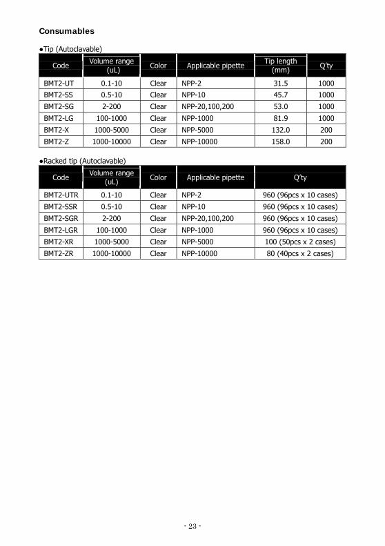
Consumables ●Tip (Autoclavable)
Code Volume range (uL) Color Applicable pipette Tip length
(mm) Q’ty
BMT2-UT 0.1-10 Clear NPP-2 31.5 1000
BMT2-SS 0.5-10 Clear NPP-10 45.7 1000
BMT2-SG 2-200 Clear NPP-20,100,200 53.0 1000
BMT2-LG 100-1000 Clear NPP-1000 81.9 1000
BMT2-X 1000-5000 Clear NPP-5000 132.0 200
BMT2-Z 1000-10000 Clear NPP-10000 158.0 200 ●Racked tip (Autoclavable)
Code Volume range (uL) Color Applicable pipette Q’ty
BMT2-UTR 0.1-10 Clear NPP-2 960 (96pcs x 10 cases)
BMT2-SSR 0.5-10 Clear NPP-10 960 (96pcs x 10 cases)
BMT2-SGR 2-200 Clear NPP-20,100,200 960 (96pcs x 10 cases)
BMT2-LGR 100-1000 Clear NPP-1000 960 (96pcs x 10 cases)
BMT2-XR 1000-5000 Clear NPP-5000 100 (50pcs x 2 cases)
BMT2-ZR 1000-10000 Clear NPP-10000 80 (40pcs x 2 cases)
- 24 -
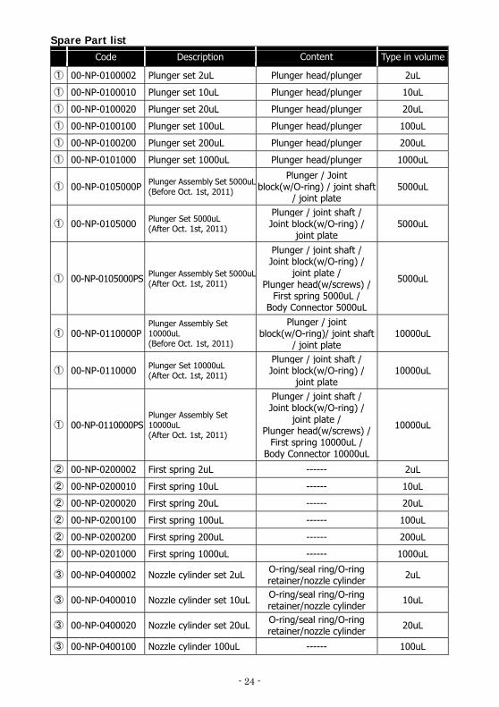
Spare Part list Code Description Content Type in volume
① 00-NP-0100002 Plunger set 2uL Plunger head/plunger 2uL
① 00-NP-0100010 Plunger set 10uL Plunger head/plunger 10uL
① 00-NP-0100020 Plunger set 20uL Plunger head/plunger 20uL
① 00-NP-0100100 Plunger set 100uL Plunger head/plunger 100uL
① 00-NP-0100200 Plunger set 200uL Plunger head/plunger 200uL
① 00-NP-0101000 Plunger set 1000uL Plunger head/plunger 1000uL
① 00-NP-0105000P Plunger Assembly Set 5000uL(Before Oct. 1st, 2011)
Plunger / Joint block(w/O-ring) / joint shaft
/ joint plate 5000uL
① 00-NP-0105000 Plunger Set 5000uL (After Oct. 1st, 2011)
Plunger / joint shaft / Joint block(w/O-ring) /
joint plate 5000uL
① 00-NP-0105000PS Plunger Assembly Set 5000uL(After Oct. 1st, 2011)
Plunger / joint shaft / Joint block(w/O-ring) /
joint plate / Plunger head(w/screws) /
First spring 5000uL / Body Connector 5000uL
5000uL
① 00-NP-0110000P Plunger Assembly Set 10000uL (Before Oct. 1st, 2011)
Plunger / joint block(w/O-ring)/ joint shaft
/ joint plate 10000uL
① 00-NP-0110000 Plunger Set 10000uL (After Oct. 1st, 2011)
Plunger / joint shaft / Joint block(w/O-ring) /
joint plate 10000uL
① 00-NP-0110000PS Plunger Assembly Set 10000uL (After Oct. 1st, 2011)
Plunger / joint shaft / Joint block(w/O-ring) /
joint plate / Plunger head(w/screws) /
First spring 10000uL / Body Connector 10000uL
10000uL
② 00-NP-0200002 First spring 2uL ------ 2uL
② 00-NP-0200010 First spring 10uL ------ 10uL
② 00-NP-0200020 First spring 20uL ------ 20uL
② 00-NP-0200100 First spring 100uL ------ 100uL
② 00-NP-0200200 First spring 200uL ------ 200uL
② 00-NP-0201000 First spring 1000uL ------ 1000uL
③ 00-NP-0400002 Nozzle cylinder set 2uL O-ring/seal ring/O-ring retainer/nozzle cylinder 2uL
③ 00-NP-0400010 Nozzle cylinder set 10uL O-ring/seal ring/O-ring retainer/nozzle cylinder 10uL
③ 00-NP-0400020 Nozzle cylinder set 20uL O-ring/seal ring/O-ring retainer/nozzle cylinder 20uL
③ 00-NP-0400100 Nozzle cylinder 100uL ------ 100uL
- 25 -
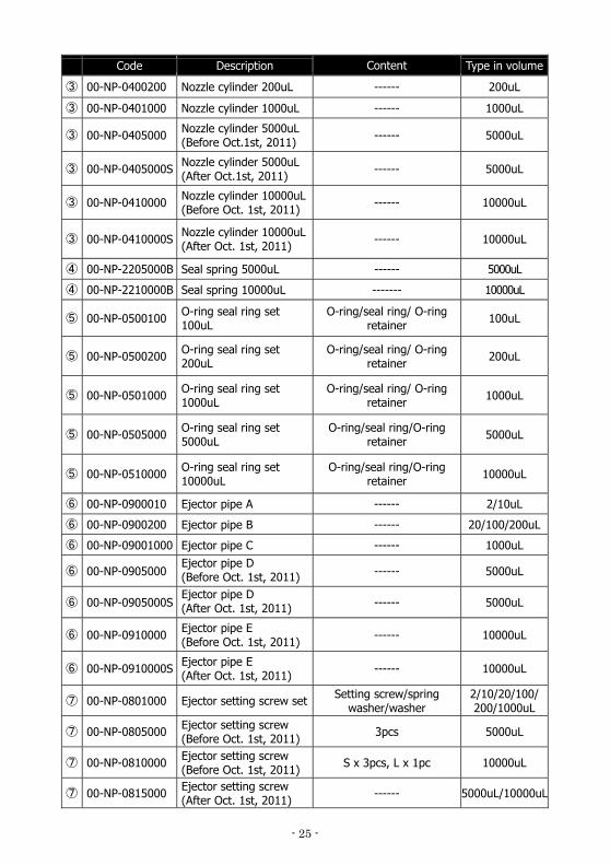
Code Description Content Type in volume
③ 00-NP-0400200 Nozzle cylinder 200uL ------ 200uL
③ 00-NP-0401000 Nozzle cylinder 1000uL ------ 1000uL
③ 00-NP-0405000 Nozzle cylinder 5000uL (Before Oct.1st, 2011) ------ 5000uL
③ 00-NP-0405000S Nozzle cylinder 5000uL (After Oct.1st, 2011) ------ 5000uL
③ 00-NP-0410000 Nozzle cylinder 10000uL(Before Oct. 1st, 2011) ------ 10000uL
③ 00-NP-0410000S Nozzle cylinder 10000uL(After Oct. 1st, 2011) ------ 10000uL
④ 00-NP-2205000B Seal spring 5000uL ------ 5000uL
④ 00-NP-2210000B Seal spring 10000uL ------- 10000uL
⑤ 00-NP-0500100 O-ring seal ring set 100uL
O-ring/seal ring/ O-ring retainer 100uL
⑤ 00-NP-0500200 O-ring seal ring set 200uL
O-ring/seal ring/ O-ring retainer 200uL
⑤ 00-NP-0501000 O-ring seal ring set 1000uL
O-ring/seal ring/ O-ring retainer 1000uL
⑤ 00-NP-0505000 O-ring seal ring set 5000uL
O-ring/seal ring/O-ring retainer 5000uL
⑤ 00-NP-0510000 O-ring seal ring set 10000uL
O-ring/seal ring/O-ring retainer 10000uL
⑥ 00-NP-0900010 Ejector pipe A ------ 2/10uL
⑥ 00-NP-0900200 Ejector pipe B ------ 20/100/200uL
⑥ 00-NP-09001000 Ejector pipe C ------ 1000uL
⑥ 00-NP-0905000 Ejector pipe D (Before Oct. 1st, 2011) ------ 5000uL
⑥ 00-NP-0905000S Ejector pipe D (After Oct. 1st, 2011) ------ 5000uL
⑥ 00-NP-0910000 Ejector pipe E (Before Oct. 1st, 2011) ------ 10000uL
⑥ 00-NP-0910000S Ejector pipe E (After Oct. 1st, 2011) ------ 10000uL
⑦ 00-NP-0801000 Ejector setting screw set Setting screw/spring washer/washer
2/10/20/100/ 200/1000uL
⑦ 00-NP-0805000 Ejector setting screw (Before Oct. 1st, 2011) 3pcs 5000uL
⑦ 00-NP-0810000 Ejector setting screw (Before Oct. 1st, 2011) S x 3pcs, L x 1pc 10000uL
⑦ 00-NP-0815000 Ejector setting screw (After Oct. 1st, 2011) ------ 5000uL/10000uL
- 26 -
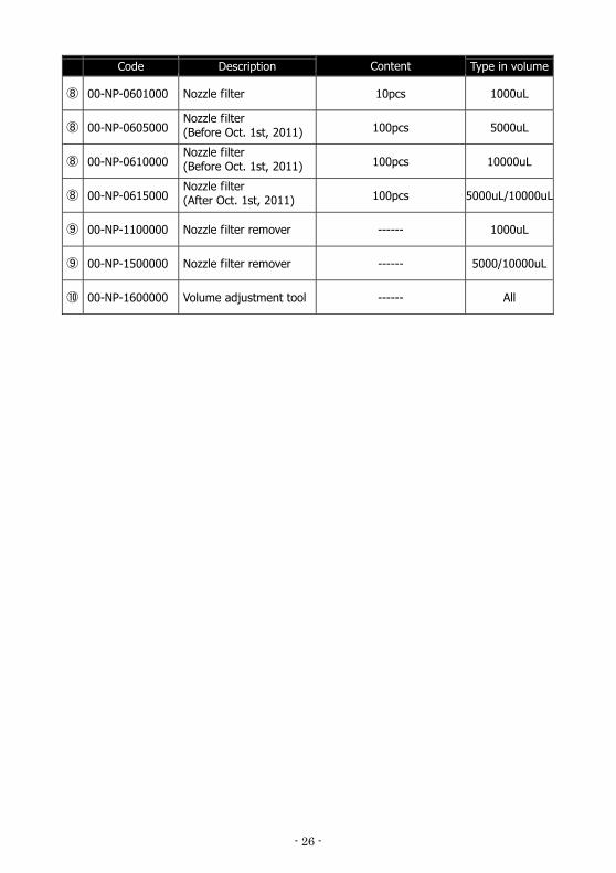
Code Description Content Type in volume
⑧ 00-NP-0601000 Nozzle filter 10pcs 1000uL
⑧ 00-NP-0605000 Nozzle filter (Before Oct. 1st, 2011) 100pcs 5000uL
⑧ 00-NP-0610000 Nozzle filter (Before Oct. 1st, 2011) 100pcs 10000uL
⑧ 00-NP-0615000 Nozzle filter (After Oct. 1st, 2011) 100pcs 5000uL/10000uL
⑨ 00-NP-1100000 Nozzle filter remover ------ 1000uL
⑨ 00-NP-1500000 Nozzle filter remover ------ 5000/10000uL
⑩ 00-NP-1600000 Volume adjustment tool ------ All
- 27 -
For repair, service or information you may contact your local distributor. Manufacturer:
Tokyo office 1-10-1 Kandanishiki-cho, Chiyoda-ku, Tokyo 101-0054, Japan TEL: +81-3-6273-7652(English) FAX: +81-3-6273-7944
URL: http://www.nichiryo.co.jp/ E-mail: [email protected]
2013.Ver.1