Embed Size (px)
Citation preview
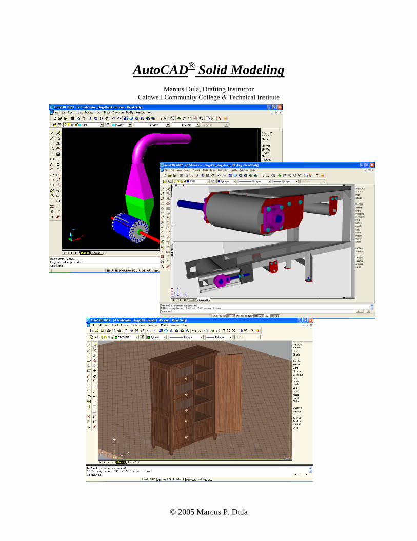
AutoCAD® Solid Modeling
Marcus Dula, Drafting Instructor
Caldwell Community College & Technical Institute
© 2005 Marcus P. Dula

BASIC COMMANDS
A good 3D model begins with good 2D geometry. This means all corners must meet perfectly.
Geometry that almost meets or geometry that crosses itself will cause problems. Any imperfections, no matter how small, will prevent geometry from being modeled. Lines on top of lines is another situation that will cause basic modeling commands to fail. Solid modeling can only be done with good clean entities.
PEDIT
This commands converts individual entities into a single polyline. If all the end points of a shape or profile meet perfectly the polyline is “closed” and will successfully extrude or revolve. If the profile contains imperfect geometry it will have to be corrected. Under the Modify pulldown, select Object, then select Polyline or type in PEDIT at the command line. Using the Multiple option once the command is started will allow the conversion of several profiles to polylines at once. Also, by entering a reasonable “fuzz” distance this feature will automatically correct geometry imperfections. BOUNDARY Another way of creating a polyline. Under the Draw pulldown, select Boundary. By picking an internal point of the desired shape this command creates a polyline and retains the original entities on screen. Once again, the profile must made up of perfect geometry. REGION Both regions and closed polylines are acceptable entities to create models from. Under the Draw pulldown, select Region to start the command. Select all entities making up the profile to create a region. As always, if the geometry contains imperfections no regions will be created. Regions and polylines have some different properties, but for modeling purposes the two may be used interchangeably. EXTRUDE Once a closed polyline or region exists the extrude command turns it into a genuine 3D solid. Enter the height of the object and taper angle (if any) if the extrusion is to be in a straight line. In constructing something of an irregular shape, such as a garden hose or dust piping use the extrude about a Path option. The path must be defined by a polyline. In this situation the polyline representing the path to extrude about does not have to be a closed profile. Note: When picking Extrude from a toolbar be sure to select “Extrude” from the Solids toolbar, not “Extrude Faces” from the Solids Editing toolbar. These commands have identical icons.
Straight Extrusion Extrusion with Taper Angle Extrusion about a Path
© 2005 Marcus P. Dula 2

REVOLVE Any part that would be machined on a lathe, either metal or wood, is a likely candidate for the Revolve command. Start by creating only one half of the desired profile as a closed polyline. The axis to revolve around is the center line of the part.
Half of a profile (as a closed polyline) After Revolving through 360 degrees SUBTRACT Subtract removes material from a 3D solid. The material to be subtracted must also be created and then placed in the proper location. The main part and the material to subtract must occupy the same space or no material will be removed. All of the material subtracted will disappear.
Object with spheres interfering Object after subtraction ROTATE 3D While the standard rotate holds entities in the XY plane, the 3D Rotate allows rotation that involves the Z axis. This works well to change the orientation of entities without having to change the UCS.
Profile flat in XY plane Profile copied and 3D Rotated to YZ plane
© 2005 Marcus P. Dula 3
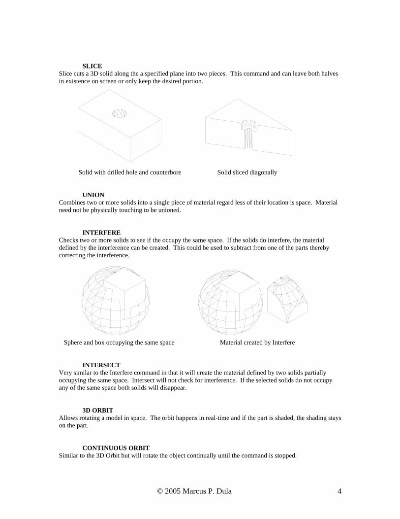
SLICE Slice cuts a 3D solid along the a specified plane into two pieces. This command and can leave both halves in existence on screen or only keep the desired portion.
Solid with drilled hole and counterbore Solid sliced diagonally
UNION Combines two or more solids into a single piece of material regard less of their location is space. Material need not be physically touching to be unioned. INTERFERE Checks two or more solids to see if the occupy the same space. If the solids do interfere, the material defined by the interference can be created. This could be used to subtract from one of the parts thereby correcting the interference.
Sphere and box occupying the same space Material created by Interfere INTERSECT Very similar to the Interfere command in that it will create the material defined by two solids partially occupying the same space. Intersect will not check for interference. If the selected solids do not occupy any of the same space both solids will disappear. 3D ORBIT Allows rotating a model in space. The orbit happens in real-time and if the part is shaded, the shading stays on the part. CONTINUOUS ORBIT Similar to the 3D Orbit but will rotate the object continually until the command is stopped.
© 2005 Marcus P. Dula 4

3D ADJUST CLIP PLANES Defines an imaginary plane to cut an object when viewing in 3D Orbit. This is used to look inside a part to see any internal features or details. Use “Front clip on/off” or “Back clip on/off “ to turn off the clip plane. SHADE Colors an entire model based of the color of the layer the part is on. Several shading options are available but “Gouraud Shaded” is the most realistic.
Unhidden and unshaded objects Objects Gouraud Shaded HIDE Displays a model without showing the lines or surfaces that would not be naturally seen with the naked eye.
Unhidden objects Objects hidden
© 2005 Marcus P. Dula 5

ISOLINES Short for “Isometric Lines”. The value of this variable controls the number of lines shown on a solid.
Isolines set to 4 Isolines set to 16 DISPSILH Short for “Display Silhouette”. Setting this value to “1” and then using the Hide command shows a more realistic view by not showing the isolines on the model.
Dispsilh set to 0 Dispsilh set to 1 FACETRES Short for “Facet Resolution”. Variable controlling the smoothness of rendered or shaded objects. Default value is 0.5. Maximum value is 10.
Facetres set to 0.5 Facetres set to 10
© 2005 Marcus P. Dula 6

RENDERING
MATLIB
Materials Library. This displays the list of available materials. Select a material from the list and pick the preview button to for a sample rendering. Choose the “<-Import” button to add this material to the list of materials used in the current drawing. Click OK when done.
RMAT
Allows the applying of materials to solid models. The material(s) previously selected will appear in the list. Select the desired material and pick the Attach button to actually apply this to the solid model on screen. Click OK when done. Also, new materials can be created by clicking “New”.
RENDER Under “Rendering Type”, choose Photo Real. This will generate the most realistic image. Under “More Options” button, set the Anti-Aliasing to High. This creates more smoothly rounded surfaces and edges similar to the FACETRES variable. Other useful features can be changed under the “Background” button. Choose the “Render” button when done.
© 2005 Marcus P. Dula 7

RENDER continued
Shaded cabinet top Rendered with Pale Marble material
White Ash Tan Marble
© 2005 Marcus P. Dula 8

MULTIPLE VIEWPORTS The normal drawing area is called Modelspace. To create multiple viewports, change to Paperspace by clicking the word “Model” on the status bar or clicking the “Layout 1” tab just below the drawing area. This may automatically launch the Plot dialog box. If so, cancel it. This leaves a single viewport containing the solid model. To avoid confusion this viewport needs to be erased. MVIEW While in Paperspace, use the Mview command to create new viewports. Many can be created and they do not have to be rectangular. Each viewport will display the solid model(s). To adjust views, click the “Paper” tab on the status bar. This will allow making a single view active. Once a viewport is active it behaves exactly as Modelspace the 3D solid was created in. To change which viewport is active, click once inside it.
Original object in Modelspace Paperspace with 4 viewports and different views
Paperspace with Polygonal viewport Any change made to the model in any viewport will be evident in all viewports. To erase or change the size of a viewport, change back to Paperspace and use the normal editing commands. Use grips or the Stretch command to resize a viewport. Viewports can also be copied. Ideally, viewports should be created in a separate layer. This will allow them to be turned off and prevent the viewports themselves from being seen when the layout is plotted.
© 2005 Marcus P. Dula 9

PLOTTING From Modelspace, print normally. To prevent hidden lines from being printed be sure to check the “Hide
Objects” toggle in the lower right corner of the plot dialog box.
Print Preview with Hide Objects checked Print Preview with objects not hidden
© 2005 Marcus P. Dula 10

From Paperspace, use the MVIEW command to turn “Hideplot” on and select the desired viewports. This prevents hidden lines from being printed. If “Hideplot” is not turned on the hidden lines will not be removed regardless of whether the object is hidden on screen or if the “Hide Objects” toggle in the plot dialog box is checked. The “Hide Objects” toggle has no effect when printing from paperspace. “Hideplot” was changed to “Shadeplot” with release 2004.
Print Preview with Hideplot off Print Preview with Hideplot turned ON
COMBINE WORKING DRAWING WITH SOLID MODEL (1) Construct solid model in the same drawing file as the dimensioned 2D views in modelspace.
© 2005 Marcus P. Dula 11

(2) Setup a layout and resize a single viewport to the desired location of the printing area. The viewport
) Switch back to Modelspace and copy the dimensioned, 2D views to the clipboard. Do Not copy the
should be in its own layer so it can be turned off later.
(3solid model to the clipboard.
© 2005 Marcus P. Dula 12

(4) Change back to the Paperspace Layout and paste the 2D entities from the clipboard. In the image below, the page size has been increased from the default, the border has been stretched to enclose the viewport, the model has been shaded and the layer containing the viewport has been turned off.
Note: AutoCAD releases 2002 and previous will not printed a shaded model. Although the model is shaded on screen, only the wireframe image will be printed. Releases 2004 and newer will print shaded objects.
PRINTING RENDERINGS Apply desired materials to the model and render the object.
© 2005 Marcus P. Dula 13

Use the “Shadeplot” option under the MVIEW command. This is only available in releases 2004 and more recent. Select the desired setting (hidden, rendered, as displayed, etc) and print normally. Rendered images can also be saved for use in other software; In the Render dialog box, under Destination, select File. This will render the image to a .bmp file and will allow the image to be saved. Select the “More Options” button to increase the resolution to at least 800x600. When the “Render” button is picked, another dialog box will appear to specify where the image is to be saved and what it is to be named. When rendering to a file then image on screen will not change.
Rendered images can also be imported into MS Word, Powerpoint, etc. for use in presentations or as a simpler means of printing.
© 2005 Marcus P. Dula 14

OTHER TOPICS
SETUV This command allows changing the rendered overall grain direction of wooden or marble objects. Not all materials have an apparent grain direction.
Normal grain direction Grain changed to a different plane DDUCS Changes the orientation of X, Y and Z axes relative to the object(s). Most useful options are found under the “Orthographic UCS” tab. Screen Capture Pressing ALT+PRINT SCREEN copies the entire image from the computer monitor to the clipboard. This can then be pasted into various other software packages. This is not specific to AutoCAD applications.
END
© 2005 Marcus P. Dula 15