Embed Size (px)
Citation preview

8/20/2019 Autocad Reinforcement Manual Eng
http://slidepdf.com/reader/full/autocad-reinforcement-manual-eng 1/222
User Guide
Autodesk
®
March 2 1

8/20/2019 Autocad Reinforcement Manual Eng
http://slidepdf.com/reader/full/autocad-reinforcement-manual-eng 2/222
© 2010 Autodesk, Inc. All Rights Reserved. Except as otherwise permitted by Autodesk, Inc., thispublication, or parts thereof, may not be reproduced in any form, by any method, for any purpose.Certain materials included in this publication are reprinted with the permission of the copyrightholder.
DisclaimerTHIS PUBLICATION AND THE INFORMATION CONTAINED HEREIN IS MADE AVAILABLEBY AUTODESK, INC. “AS IS.” AUTODESK, INC. DISCLAIMS ALL WARRANTIES, EITHEREXPRESS OR IMPLIED, INCLUDING BUT NOT LIMITED TO ANY IMPLIED WARRANTIESOF MERCHANTABILITY OR FITNESS FOR A PARTICULAR PURPOSE REGARDING THESEMATERIALS.
TrademarksThe following are registered trademarks of Autodesk, Inc., in the USA and/or other countries:Autodesk Robot Structural Analysis, Autodesk Concrete Building Structures, Spreadsheet Calculator, ATC,
AutoCAD, Autodesk, Autodesk Inventor, Autodesk (logo), Buzzsaw,Design Web Format, DWF, ViewCube, SteeringWheels, and Autodesk Revit.All other brand names, product names or trademarks belong to their respective holders.
Third Party Software Program CreditsACIS Copyright© 1989-2001 Spatial Corp. Portions Copyright© 2002 Autodesk, Inc.Copyright© 1997 Microsoft Corporation. All rights reserved.International CorrectSpell™ Spelling Correction System© 1995 by Lernout & Hauspie SpeechProducts, N.V. All rights reserved.InstallShield™ 3.0. Copyright© 1997 InstallShield Software Corporation. All rights reserved.PANTONE® and other Pantone, Inc. trademarks are the property of Pantone, Inc.© Pantone, Inc.,2002.Portions Copyright© 1991-1996 Arthur D. Applegate. All rights reserved.Portions relating to JPEG © Copyright 1991-1998 Thomas G. Lane. All rights reserved. Portions ofthis software are based on the work of the Independent JPEG Group.Portions relating to TIFF © Copyright 1997-1998 Sam Leffler. © Copyright 1991-1997 SiliconGraphics, Inc. All rights reserved.
Government Use
Use, duplication, or disclosure by the U.S. Government is subject to restrictions as set forth inFAR 12.212 (Commercial Computer Software-Restricted and DFAR 227.7202 (Rights inRights)Technical Data and Computer Software), as applicable.
8/20/2019 Autocad Reinforcement Manual Eng
http://slidepdf.com/reader/full/autocad-reinforcement-manual-eng 3/222
AutoCAD Structural Detailing - Reinforcement - User Guide page: i
TABLE OF CONTENTS
1. PROGRAM DESCRIPTION ......................................................................................................... 1
1.1. GENERAL DESCRIPTION OF THE PROGRAM ................................................................ .................. 1 1.2. STAGES OF WORK ON STRUCTURE PROJECT DRAWINGS .............................................................. 1 1.3. EXAMPLE OF LOADING A DRAWING CREATED IN R OBOT ............................................................ 2 1.4. OPTIONS AVAILABLE IN THE MENU ...................................................... ....................................... 4 1.5. R IBBON .................................................................................................................................... 20
2. CONFIGURATION ........................................................................ .............................................. 21
2.1. JOB PREFERENCES .................................................................................................................... 21 2.1.1. Job preferences .................................................................. .............................................. 21 2.1.2. Units ................................................................................................................................ 22 2.1.3. Codes / Materials .................................................................. ........................................... 23 2.1.4. Options ............................................................................................................................ 25 2.1.5. Display (bars) ................................................................... ............................................... 26
2.1.6. Distributions (bars) ......................................................................................................... 28 2.1.7. Options (bars) ........................................................... ....................................................... 28 2.1.8. Styles (bars) ................................................................................................................. .... 30 2.1.9. Display (wire fabrics) .............................................................. ........................................ 30 2.1.10. Styles (wire fabrics) ................................................................................................... ...... 32 2.1.11. Styles (steel profiles) ............................................................... ......................................... 32 2.1.12. Styles (s ymbols) ............................................................................................................... 33
2.2. PREFERENCES ...................................................... ............................................................... ...... 34 2.2.1. Preferences ............................................................. ......................................................... 34
3. OBJECT INSPECTOR .................................................................. ............................................... 37
3.1. OBJECT I NSPECTOR DESCRIPTION ............................................................................................ 37 3.2. MODEL ..................................................................................................................................... 38
3.3. POSITIONS ................................................................................................................................ 40 3.4. STRUCTURAL DETAILING CENTER ............................................................................................ 41 3.5. PRINTOUTS .......................................................... ............................................................... ...... 41
4. TYPICAL STRUCTURES ........................................................................................................... 42
4.1. R EINFORCEMENT / FORMWORK OF TYPICAL RC STRUCTURE ELEMENTS ................................... 42
5. RULES APPLIED WHILE DEFINING REINFORCEMENT ................................................. 44
5.1. LOCATION OF A REINFORCING BAR IN A DRAWING ................................................................... 44 5.2. A NGLE OF HOOK BENDING ........................................................ ................................................ 44
6. DEFINITION OF REINFORCEMENT - LONGITUDINAL REINFORCEMENT .............. 45
6.1. DEFINITION OF BAR REINFORCEMENT - LONGITUDINAL REINFORCEMENT ................... 45 6.2. STRAIGHT BAR ......................................................................................................................... 46 6.3. DEFINITION OF A STRAIGHT BAR (LONGITUDINAL REINFORCEMENT) ........................................ 47 6.4. STRAIGHT BAR WITH ANCHOR ELEMENT ........................................................ ........................... 47 6.5. DEFINITION OF A STRAIGHT BAR WITH ANCHORS (LONGITUDINAL REINFORCEMENT) ............... 48 6.6. BENT BAR - TYPE 1 ................................................................................................................... 49 6.7. DEFINITION OF A BENT BAR (TYPE 1) - LONGITUDINAL REINFORCEMENT .................................. 50 6.8. BENT BAR - TYPE 2 ................................................................................................................... 50 6.9. BAR FROM DATABASE .............................................................................................................. 51 6.10. ARBITRARY SHAPE OF A BAR ................................................................................................ 53 6.11. R EINFORCEMENT DESCRIPTION ............................................................................................ 54 6.12. USER DESCRIPTION - AUTOCAD PROGRAM MECHANISMS .................................................... 55 6.13. COMMANDS FROM THE COMMAND LINE - DEFINITION OF LONGITUDINAL REINFORCEMENT . 56 6.14. EXAMPLE OF DEFINITION OF LONGITUDINAL REINFORCEMENT ............................................. 57
© 2010 Autodesk, Inc. All rights reserved

8/20/2019 Autocad Reinforcement Manual Eng
http://slidepdf.com/reader/full/autocad-reinforcement-manual-eng 4/222
page: ii AutoCAD Structural Detailing - Reinforcement - User Guide
7. DEFINITION OF REINFORCEMENT - TRANSVERSAL REINFORCEMENT ................ 59
7.1. DEFINITION OF BAR REINFORCEMENT - TRANSVERSAL REINFORCEMENT .................... 59 7.2. R ECTANGULAR (CLOSED) STIRRUP ........................................................................................... 60 7.3. R OUND STIRRUP ....................................................................................................................... 61 7.4. PIN ........................................................................................................................................... 62 7.5. SHACKLE .................................................................................................................................. 63 7.6. BAR FROM DATABASE .............................................................................................................. 64 7.7. ARBITRARY BAR SHAPE ............................................................................................................ 66 7.8. DESCRIPTION OF REINFORCEMENT ........................................................................................... 67 7.9. COMMANDS FROM THE COMMAND LINE - DEFINITION OF TRANSVERSAL REINFORCEMENT ...... 68 7.10. EXAMPLE OF DEFINITION OF TRANSVERSAL REINFORCEMENT .............................................. 69
8. DEFINITION OF REINFORCEMENT - SPECIAL STIRRUPS............................................. 72
8.1. DEFINITION OF BAR REINFORCEMENT - BAR SECTION (SPECIAL STIRRUPS) .................. 72 8.2. SPECIAL STIRRUPS - FOUR -LEG STIRRUPS ................................................................................. 73 8.3. SPECIAL STIRRUPS - BARS IN THE SHAPE OF THE DOUBLE U-LETTER ......................................... 74
9. DEFINITION OF REINFORCEMENT - POINT REINFORCEMENT ................................. 75
9.1. POINT REINFORCEMENT ............................................................................................................ 75 9.2. R EGULAR DISTRIBUTION OF REINFORCEMENT .......................................................................... 76 9.3. AUTOMATIC DISTRIBUTION OF REINFORCEMENT ...................................................................... 77 9.4. A NY REINFORCEMENT DISTRIBUTION ....................................................................................... 78 9.5. R EINFORCEMENT DESCRIPTION ................................................................................................ 79 9.6. EXAMPLE OF DEFINITION OF POINT REINFORCEMENT .......................................................... ..... 80
10. DEFINITION OF REINFORCEMENT - SPECIAL BARS .................................................. 83
10.1. SPECIAL REINFORCEMENT .................................................................................................... 83 10.2. CREST-SHAPED REINFORCEMENT ......................................................................................... 84 10.3. EXAMPLE DEFINITION OF CREST-SHAPED REINFORCEMENT .................................................. 85 10.4. ARC-SHAPED REINFORCEMENT ........................................................ ..................................... 86 10.5. 'GOALPOSTS' REINFORCEMENT ........................................................................................... .. 87
10.6. CORBEL REINFORCEMENT .................................................................................................... 89 10.7. EXAMPLE DEFINITION OF CORBEL REINFORCEMENT ............................................................. 90 10.8. HELIX ................................................................................................................................... 91 10.9. EXAMPLE OF HELIX DEFINITION ....................................................... ..................................... 93 10.10. VERTICAL LOOP .................................................................................................................... 94 10.11. TRANSPORT HANDLES .......................................................................................................... 95
11. WIRE FABRICS IN CROSS SECTION ................................................................... .............. 96
11.1. WIRE FABRICS IN CROSS SECTION – WIRE FABRIC SHAPE ...................................................... 96 11.2. R EINFORCEMENT DESCRIPTION - WIRE FABRIC SHAPE .......................................................... 97
12. WIRE FABRIC DISTRIBUTION .......................................................................................... . 99
12.1. WIRE FABRIC DISTRIBUTION ............................................................ ..................................... 99
13. REINFORCEMENT DISTRIBUTION - REINFORCING BARS ..................................... 100
13.1. R EINFORCEMENT DISTRIBUTION ......................................................................................... 100 13.2. DISTRIBUTION OF SEVERAL BARS SIMULTANEOUSLY ...................................................... ... 102 13.3. LINEAR DISTRIBUTION .......................................................... .............................................. 102 13.4. LINEAR DISTRIBUTION (ZONE) ............................................................................................ 102 13.5. LINEAR DISTRIBUTION (MODULE) ............................................................... ........................ 104 13.6. LI NEAR DISTRIBUTION (CAQUOT) ....................................................................................... 104 13.7. DISTRIBUTION VARYING LINEARLY .................................................................................... 105 13.8. DISTRIBUTION VARYING LINEARLY (ZONE) ........................................................................ 105 13.9. DISTRIBUTION VARYING LINEARLY (MODULE) ................................................................... 107 13.10. DISTRIBUTION VARYING LINEARLY (CAQUOT) ...................................................... ............. 108 13.11. GENERATION OF DISTRIBUTION VARYING LINEARLY AND DETAILED TABLE ....................... 108
13.12. ARC DISTRIBUTION ............................................................................................................. 110 13.13. DISTRIBUTION ALONG THE POLYLINE ................................................................................. 111
© 2010 Autodesk, Inc. All rights reserved

8/20/2019 Autocad Reinforcement Manual Eng
http://slidepdf.com/reader/full/autocad-reinforcement-manual-eng 5/222
AutoCAD Structural Detailing - Reinforcement - User Guide page: iii
13.14. R EINFORCEMENT DISTRIBUTION - ALONG POLYLINE .......................................................... 112 13.15. A NY DISTRIBUTION............................................................................................................. 113
14. SURFACE REINFORCEMENT DISTRIBUTION - WIRE FABRICS ............................ 113
14.1. SURFACE REINFORCEMENT - WIRE FABRICS ........................................................................ 113 14.2. WIRE FABRIC DISTRIBUTION - MANUAL MODE .................................................................... 116
14.3. WIRE FABRIC DISTRIBUTION - AUTOMATIC MODE ............................................................... 117 14.4. EXAMPLE OF DEFINITION OF WIRE FABRIC SURFACE DISTRIBUTION .................................... 120
15. SURFACE REINFORCEMENT DISTRIBUTION - BARS ............................................... 121
15.1. SURFACE REINFORCEMENT - BARS ...................................................................................... 121 15.2. R EINFORCEMENT - DEFINITION AND DETAILING ................................................................. 126 15.3. R EINFORCEMENT ....................................................... ......................................................... 126 15.4. SHAPE ................................................................................................................................ 127 15.5. OPENINGS ........................................................................................................................... 127 15.6. R EINFORCEMENT DETAILING ........................................................... ................................... 128 15.7. DETAILING OPTIONS ........................................................................................................... 129 15.8. R EINFORCEMENT LAP ......................................................................................................... 130 15.9. ADDITIONAL PARAMETERS .............................................................. ................................... 131
15.10. DESCRIPTION OF REINFORCEMENT DISTRIBUTION .............................................................. 131 15.11. EXAMPLE DEFINITION OF SURFACE BAR DISTRIBUTION ...................................................... 133
16. SURFACE REINFORCEMENT DISTRIBUTION - BARS (RADIAL
REINFORCEMENT) ................................................................... ....................................................... 134
16.1. R ADIAL REINFORCEMENT - BARS ........................................................................................ 134 16.2. R ADIAL/POLAR REINFORCEMENT - DEFINITION AND DETAILING ......................................... 136 16.3. R EINFORCEMENT SHAPE ..................................................................................................... 136 16.4. R EINFORCEMENT DISTR IBUTION ...................................................... ................................... 137 16.5. DISTRIBUTION OPTIONS ........................................................ .............................................. 138 16.6. LAP SPLICE ......................................................................................................................... 140 16.7. R EINFORCEMENT DESCRIPTION - RADIAL/POLAR REINFORCEMENT ..................................... 141
17. STEEL PROFILES ................................................................. ................................................ 142 17.1. STEEL PROFILES .................................................................................................................. 142 17.2. DESCRIPTION OF A STEEL PROFILE ...................................................................................... 143 17.3. OPERATIONS PERFORMED ON STEEL PROFILES ...................................................... .............. 144
18. ELEMENT MANAGER ......................................................................................................... 145
18.1. ELEMENT MANAGER ............................................................. .............................................. 145
19. REINFORCEMENT MODIFICATION .................................................................. ............. 147
19.1. LONGITUDINAL REINFORCEMENT (REINFORCEMENT - ELEVATION) - MODIFICATION ......... 147 19.2. TRANSVERSAL REINFORCEMENT (REINFOR CEMENT - SECTION) - MODIFICATION ................ 147 19.3. SPECIAL REI NFORCEMENT - MODIFICATION ........................................................................ 148 19.4. LAP SPLICES ....................................................................................................................... 149 19.5. WIRE FABRIC LAP SPLICES .................................................................................................. 150 19.6. MODIFICATION OF REINFORCEMENT GRAPHICAL PARAMETERS .......................................... 151 19.7. MODIFICATION OF GRAPHICAL PARAMETERS OF REINFORCEMENT (BARS) ......................... 151 19.8. MODIFICATION OF GRAPHICAL PARAMETERS OF REINFORCEMENT (WIRE FABRICS) ............ 153 19.9. WIRE FABRICS IN CROSS SECTION - WIRE FABR IC SHAPE - MODIFICATION ........................... 153 19.10. EXAMPLE OF REINFORCEMENT MODIFICATION ................................................................... 154
20. DESCRIPTION OF REINFORCEMENT ............................................................................ 156
20.1. DESCRIPTION OF REINFORCEME NT SHAPE ............................................................. .............. 156 20.2. R EINFORCEMENT DESCRIPTION .......................................................................................... 157 20.3. BARS .................................................................................................................................. 157
20.3.1. Bar shape ........................................................... ............................................................ 157
20.3.2. Description elements ................................................................... .................................. 158 20.3.3. Description syntax ..................................................................... .................................... 159 20.3.4. Bar ends - reinforcement description ............................................................................ 160
© 2010 Autodesk, Inc. All rights reserved

8/20/2019 Autocad Reinforcement Manual Eng
http://slidepdf.com/reader/full/autocad-reinforcement-manual-eng 6/222
page: iv AutoCAD Structural Detailing - Reinforcement - User Guide
20.3.5. Distribution - Bar ends - Reinforcement description ..................................................... 162 20.3.6. Distribution - element view ..................................................................... ....................... 163 20.3.7. Description elements ................................................................... .................................. 163 20.3.8. Description syntax ..................................................................... .................................... 165 20.3.9. Bar symbol ............................................................. ........................................................ 166 20.3.10. Description elements .............................................................. ................................... 167
20.3.11. Description syntax ................................................................................................. .... 168 20.4. WIRE FABRICS ........................................................... ......................................................... 169
20.4.1. Wire fabric shape........................................................................................................... 169 20.4.2. Description elements ................................................................... .................................. 169 20.4.3. Descrption syntax ..................................................................... ..................................... 171 20.4.4. Wire fabric distribution ..................................................................... ............................ 172 20.4.5. Description elements ................................................................... .................................. 172 20.4.6. Description syntax ..................................................................... .................................... 174 20.4.7. Wire fabric symbol ........................................................ ................................................. 175 20.4.8. Description elements ................................................................... .................................. 175 20.4.9. Description s yntax ..................................................................... .................................... 176
20.5. STEEL PROFILES ......................................................... ......................................................... 177 20.5.1. Steel profile ................................................................. ................................................... 177
20.5.2. Description elements ................................................................... .................................. 177 20.5.3. Description syntax ..................................................................... .................................... 179
21. STYLES OF SYMBOLS ..................................................................... .................................... 180
21.1. STYLES OF SYMBOLS .......................................................................................................... 180 21.2. AXIS ................................................................ ................................................................ ... 181 21.3. ELEVATION MARK .......................................................................................................... .... 181 21.4. SECTION SYMBOL ............................................................................................................... 182 21.5. GRAPHIC DESIGNATIO N ...................................................................................................... 183 21.6. SECTION DESCRIPTION .......................................................... .............................................. 184
22. DRAWING TEMPLATE STYLES ....................................................................................... 185
22.1. CONSTRUCTION DRAWINGS - SETTINGS .............................................................................. 185
22.2. ADJOINING ELEMENTS .......................................................... .............................................. 186 22.3. SECTION / VIEW - PARAMETERS ....................................................... ................................... 186 22.4. DRAWING LAYOUT ............................................................................................................. 188 22.5. DIMENSIONING ................................................................................................................... 188 22.6. R EINFORCEMENT DESCRIPTION .......................................................................................... 189
23. REINFORCEMENT TABLES............................................................................................... 191
23.1. R EINFORCEMENT TABLES (STYLE MANAGER ) ........................................................ ............. 191 23.2. STYLE DEFINITION/MODIFICATION ..................................................................................... 192
23.2.1. Definition/modification of reinforcement table style ..................................................... 192 23.2.2. Table layout and components ........................................................................................ 192 23.2.3. Font, color, line ............................................................................................................. 194 23.2.4. Options .......................................................................................................................... 194 23.2.5. Sorting and detailed options ............................................................ .............................. 195 23.2.6. Display options (wire fabric cuts) .................................................................... ............. 196
24. PRINTOUT ....................................................... ..................................................................... .. 197
24.1. TABLE PRINTOUT MA NAGER ............................................................ ................................... 197 24.2. TABLE COMPOSITION ............................................................ .............................................. 199 24.3. PAGE SETUP ............................................................... ......................................................... 200 24.4. FRAMES .............................................................................................................................. 200 24.5. DISTANCES ...................................................... ............................................................... .... 201 24.6. COLORS AND FORMATS ...................................................................................................... 201 24.7. HEADER .............................................................................................................................. 202 24.8. FOOTER .............................................................................................................................. 202 24.9. PARAMETER S ............................................................. ......................................................... 202 24.10. TEMPLATES .................................................................................................................... .... 204
© 2010 Autodesk, Inc. All rights reserved

8/20/2019 Autocad Reinforcement Manual Eng
http://slidepdf.com/reader/full/autocad-reinforcement-manual-eng 7/222
AutoCAD Structural Detailing - Reinforcement - User Guide page: v
© 2010 Autodesk, Inc. All rights reserved
24.11. EXAMPLE OF DEFINITION OF VIEWS AND GENERATION OF THE FINAL DRAWING ................. 204 24.12. LIST OF COMMANDS AVAILABLE IN THE PRINTOUT MODULE ............................................... 207
25. TOOLS ................................................................ .................................................................. ... 210
25.1. DRAWING SCALE ................................................................................................................ 210 25.2. VIEW SCALE DEFINITION .................................................................................................... 211
25.3. DIFFERENT SCALE OF DRAWINGS IN A VIEW AND PREPARATION OF PRINTOUT .................... 211 25.4. FI ND REINFORCEMENT ........................................................................................................ 212 25.5. R EINFORCEMENT - INFORMATION .............................................................. ......................... 213 25.6. R ENUMBERING OF REINFORCEMENT POSITION ...................................................... .............. 213

8/20/2019 Autocad Reinforcement Manual Eng
http://slidepdf.com/reader/full/autocad-reinforcement-manual-eng 8/222
AutoCAD Structural Detailing - Reinforcement - User Guide page: 1
1. PROGRAM DESCRIPTION
1.1. General description of the program
AutoCAD® Structural Detail ing facilitates the preparation of final drawings of componentparts of designed structures. After completing the structure design and generating a structurecalculation model (this stage comprises calculations and verification of structure elements),the project technical documentation with required final drawings are prepared. AutoCAD® Structural Detail ing - Reinforcement provides the tools to create detaileddrawings of RC structure reinforcement. Included is a complete set of options for drawingdetails of an RC structure drawing, which are adjusted to the engineer-designer’s needs andmake it possible to draw objects in an intuitive manner. The program is divided into a threeparts as described below:
1. Edition of a drawing or part of a drawing (projections, intersections, etc.) - includingadditional drawing elements, correction of existing structure elements, adding structureelement dimensions.
2. Generation of final drawings.
3. Printout management.
AutoCAD® Structural Detail ing combined with Autodesk Robot Structural Analys is provides the tools to create a complete structural project including:
• Generation of a structure model and structure calculations.
• Structure design (e.g. calculation of reinforcement required in RC structure elements).
• Generation of final drawings allowing edition of prepared drawings.
The following objects have been distinguished in the program:
• View - a single drawing; it is always a document’s component, if it has been added to aprintout, it is simultaneously a printout’s element. NOTE: only a view (drawing) containedin a printout may be printed
• Printout - ready-to-use printout composed of views; its equivalent in the AutoCAD®
program is a layout together with AutoCAD views provided on it; for each printout there isexactly one layout corresponding to it.
The following elements detail the different stages of work on a project.
1.2. Stages of work on structure project drawings
Creating documentation for a designed structure (drawings) involves the following stages:1. Definition of documents A document is a set of drawings (views) of RC structural elements; which consists of views. Adocument cannot be printed.
© 2010 Autodesk, Inc. All rights reserved

8/20/2019 Autocad Reinforcement Manual Eng
http://slidepdf.com/reader/full/autocad-reinforcement-manual-eng 9/222
page: 2 AutoCAD Structural Detailing - Reinforcement - User Guide
2. Definition (edition) of views A view is a single drawing which always constitutes a document component. If a view is addedto a printout, then it is simultaneously a printout element. Views (drawing) can only be printedwhen contained in a printout.
3. Printout generation A printout is a prepared, ready-to-use document that consists of views. Each printoutcorresponds to a single layout.
All operations are performed in printout layouts. A printout layout is an object of the AutoCAD® program, and is used for composition of a finalprintout. For each printout layout there is one printout.
1.3. Example of loading a drawing created in Robot
To load a drawing made in an RC module of Autodesk Robot St ructural Analysis (beams,columns, spread footings, etc.), follow the steps below:
• Run the option:Menu: Reinforcement > Insert drawing from RobotRibbon: ASD - Reinforcement > Tools > Insert drawing from Robot
Toolbar: Definition-bars > Insert drawing from RobotCommand line: RBCR_TOOL_IMPORT_RM
• In the Open dialog (shown below), select a drawing from the tree located in the right-hand side of the dialog (in this case these are Drawing1 and Drawing2 on the standardlevel, belonging to the RC Beams project).NOTE: If the Import of printouts option is selected, then drawings prepared for printing inRobot are loaded.
© 2010 Autodesk, Inc. All rights reserved

8/20/2019 Autocad Reinforcement Manual Eng
http://slidepdf.com/reader/full/autocad-reinforcement-manual-eng 10/222
AutoCAD Structural Detailing - Reinforcement - User Guide page: 3
• Click Open; the selected drawings of an RC beam are loaded to AutoCAD® StructuralDetailing - Reinforcement. In the Object Inspector dialog, on the Positions tab foreach drawing, positions are created that include the appropriate views of the RC beamelements (as shown below).
In AutoCAD® Structural Detail ing - Reinforcement there is a possibility to edit the loadeddrawings and to prepare final drawings of RC structure elements.
© 2010 Autodesk, Inc. All rights reserved

8/20/2019 Autocad Reinforcement Manual Eng
http://slidepdf.com/reader/full/autocad-reinforcement-manual-eng 11/222
page: 4 AutoCAD Structural Detailing - Reinforcement - User Guide
1.4. Options available in the menu
All the options available in AutoCAD® Structural Detail ing – Rein forcement are presentedbelow. The following information is included:
• Position of the option in the text menu,
• Position of the option in the ribbon,• The icon symbolizing the option,
• Command activating the option from the command line,
• Short description of the option.See also: Ribbon
Reinforcement -elevation
Opens the Reinforcement - elevation dialog; the option defines thereinforcing bars (longitudinal reinforcement) in an element of an RCstructure.Menu: Reinforcement > Reinforcement - elevationRibbon: ASD - Reinforcement > Reinforcement - definition > Reinforcement- elevation
Toolbar: Definition-bars > Reinforcement - elevationCommand line: RBCR_DEF_BAR_BV
Reinforcement -cross-section
Opens the Reinforcement - cross-section dialog; the option definesreinforcing bars (transversal reinforcement) in a cross-section of an RCstructure element.Menu: Reinforcement > Reinforcement - section Ribbon: ASD - Reinforcement > Reinforcement - definition > Reinforcement- section
Toolbar: Definition-bars > Reinforcement - section
Command line: RBCR_DEF_BAR_BS
Special stirrups Opens the Special sti rrups dialog; this option defines special stirrups(transversal reinforcement) in the cross-section of an RC structure element.
Menu: Reinforcement > Special stirrups Ribbon: ASD - Reinforcement > Reinforcement - definition > Specialstirrups
Toolbar: Definition-bars > Special stirrups
Command line: RBCR_DEF_STIRRUP_SPEC
Reinforcement- point Opens the Reinforcement- point dialog; the option defines the distributionof reinforcement which is presented as points (reinforcement n cross-section).Menu: Reinforcement > Reinforcement - point Ribbon: ASD - Reinforcement > Reinforcement - definition >
Reinforcement - point
Toolbar: Definition-bars > Reinforcement pointCommand line: RBCR_DISTRIBUTION_POINT
Specialreinforcement
Opens the Special reinforcement dialog; the option defines particularreinforcing bars used in different elements of RC structures (e.g. crest-shaped reinforcement, corbel reinforcement, transport handles, etc.).Menu: Reinforcement > Special reinforcementRibbon: ASD - Reinforcement > Reinforcement - definition > Specialreinforcement
Toolbar: Definition-bars > Special reinforcementCommand line: RBCR_DEF_BARLIBSPECIAL
© 2010 Autodesk, Inc. All rights reserved

8/20/2019 Autocad Reinforcement Manual Eng
http://slidepdf.com/reader/full/autocad-reinforcement-manual-eng 12/222
AutoCAD Structural Detailing - Reinforcement - User Guide page: 5
Wire fabrics in crosssection
Opens the Wire Fabric Shape dialog; the option defines a wire fabric in thecross section of an RC structure element.Menu: Reinforcement > Wire fabrics in cross sectionRibbon: ASD - Reinforcement > Reinforcement - definition > Wire fabrics incross section
Toolabar: Definition-wire fabrics > Wire fabrics in cross sectionCommand line: RBCR_DEF_NET_SIDE
Wire fabrics in crosssection - symbol
The option presents an indicated wire fabric in cross section outside theformwork contour to show a full shape and geometry of a reinforcement(this is a detailed presentation of a wire fabric needed for a bar bender toshape the reinforcement properly).Menu: Reinforcement > Wire fabrics in cross section - symbolRibbon: ASD - Reinforcement > Reinforcement - definition > Wire fabrics incross section - symbol
Toolbar: Definition-wire fabrics > Wire fabrics in cross section - symbolCommand line: RBCR_DEF_NET_PULL
Reinforcement bars -legend
The option presents an indicated bar outside the formwork contour to showthe whole reinforcement shape and geometry (it is a detailed barpresentation needed for a bar bender to shape reinforcement properly).Menu: Reinforcement > Reinforcement - bar legend Ribbon: ASD - Reinforcement > Reinforcement - definition >Reinforcement bars - legend
Toolbar: Definition-bars > Reinforcement bars - legend
Command line: RBCR_DEF_PULL
Reinforcementdistribution
The option defines reinforcement distribution.Menu: Reinforcement > Reinforcement distributionRibbon: ASD - Reinforcement > Reinforcement - definition >
Reinforcement distributionToolbar: Definition-bars > Reinforcement distributionCommand line: RBCR_DISTRIBUTION
Surfacereinforcement - wirefabrics
Opens the Surface reinforcement dis tribution - wire fabrics dialog; theoption defines regions of wire fabric distribution (e.g. reinforcement of RCplates).Menu: Reinforcement > Surface reinforcement - wire fabricsRibbon: ASD - Reinforcement > Reinforcement - definition > Surfacereinforcement - wire fabrics
Toolbar: Definition-bars > Surface reinforcement-wire fabricsCommand line: RBCR_NETD_RECT
Surfacereinforcement- bars
Opens the Surface reinforcement - bars dialog; the option defines regionsof bar distribution (e.g. reinforcement of RC slabs).Menu: Reinforcement > Surface reinforcement - barsRibbon: ASD - Reinforcement > Reinforcement - definition > Surfacereinforcement - bars
Toolbar: Definition-bars > Surface reinforcement - bars
Command line: RBCR_DEF_BAR_SURF
Radial reinforcement- bars
Opens the Radial surface reinforcement dialog; the option defines radialreinforcement (e.g. reinforcement of round RC slabs).Menu: Reinforcement > Radial distribution Ribbon: ASD - Reinforcement > Reinforcement - definition > Radial
reinforcement - bars Toolbar: Definition-bars > Radial reinforcement - bars Command line: RBCR_CREATE_RADIAL
© 2010 Autodesk, Inc. All rights reserved

8/20/2019 Autocad Reinforcement Manual Eng
http://slidepdf.com/reader/full/autocad-reinforcement-manual-eng 13/222
page: 6 AutoCAD Structural Detailing - Reinforcement - User Guide
Wire fabricsdistribution
Opens the Surface reinforcement dis tribution - wire fabrics dialog; theoption defines regions of wire fabric distribution (e.g. reinforcement of RCslabs).Menu: Reinforcement > Distribution - wire fabricsRibbon: ASD - Reinforcement > Reinforcement - definition > Wire fabrics
disctributionToolbar: Definition-wire fabrics > Wire fabrics distributionCommand line: RBCR_NS_DISTRIBUTION
Steel profiles -definition
Steel profiles Opens the Steel profiles dialog; the option defines steel profiles.Menu: Reinforcement > Definition - steel profiles > Steel profilesRibbon: ASD - Reinforcement > Reinforcement - definition > Steel profiles
Toolbar: Definition - steel profiles > Steel profiles
Command line: RBCR_CREATE_STEEL_VIEW
Steel profiles -description
Opens the Profile description dialog; the option defines the indicated steelprofile.
Menu: Reinforcement > Definition - steel profiles > Steel profiles -description
Ribbon: ASD - Reinforcement > Reinforcement - definition > Steel profiles -description
Toolbar: Definition - steel profiles > Steel profiles - description
Command line: RBCR_CREATE_STEEL_DESC
Steel profiles -section
Selecting this option results in generation of a steel profile section; to createa vertical section, indicate a cutting line (two points defining a segment) anda section ‘depth’.
Menu: Reinforcement > Definition - steel profiles > Steel profiles - sectionRibbon: ASD - Reinforcement > Reinforcement - definition > Steel profiles -sectionToolbar: Definition - steel profiles > Steel profiles - sectionCommand line: RBCR_CREATE_STEEL_SECTION
Cut profile to line The option enables cutting a steel profile so that it fits a plane defined bythe line.Menu: Reinforcement > Definition - steel profiles > Cut profile to lineRibbon: ASD - Reinforcement > Reinforcement - definition > Cut profile toline
Toolbar: Definition - steel profiles > Cut profile to line
Command line: RBCR_CREATE_STEEL_CUT
Delete cut The option deletes a cut from a created steel profile.
Menu: Reinforcement > Definition - steel profiles > Delete cutRibbon: ASD - Reinforcement > Reinforcement - definition > Delete cut Toolbar: Definition - steel profiles > Delete cutCommand line: RBCR_CREATE_STEEL_CUTS
ReinforcementdescriptionBar descript ion The option describes a reinforcing bar.
Menu: Reinforcement > Reinforcement description > Bar descriptionRibbon: ASD - Reinforcement > Reinforcement - definition > Bardescription
Toolbar: Definition-bars > Bar description Command line: RBCR_BARBVFORMDESC
© 2010 Autodesk, Inc. All rights reserved

8/20/2019 Autocad Reinforcement Manual Eng
http://slidepdf.com/reader/full/autocad-reinforcement-manual-eng 14/222
AutoCAD Structural Detailing - Reinforcement - User Guide page: 7
Reinforcementdistributiondescription
The option defines reinforcement distribution.Menu: Reinforcement > Reinforcement description > Reinforcementdistribution descriptionRibbon: ASD - Reinforcement > Reinforcement - definition >Reinforcement distribution description
Toolbar: Definition-bars > Reinforcement distribution descriptionCommand line: RBCR_DISTRIB_DESC
Bar ends The option defines a symbol of bar ends.
Menu: Reinforcement > Reinforcement description > Bar endsRibbon: ASD - Reinforcement > Reinforcement - definition > Bar ends
Toolbar: Definition-bars > Bar ends
Command line: RBCR_BAR_END
Descript ion of wirefabric in crosssection
The option defines a wire fabric in the cross section.Menu: Reinforcement > Reinforcement description > Description of wirefabric in cross section
Ribbon: ASD - Reinforcement > Reinforcement - definition > Description ofwire fabric in cross section
Toolbar: Definition-wire fabrics > Description of wire fabric in cross section
Command line: RBCR_DEF_NET_SIDE_DESC
Styles ofreinforcementdescription
Opens the Descripti on of reinforcement shape dialog; the option allowsdefining description styles (format) for individual elements of reinforcement.Menu: Reinforcement > Reinforcement description > Styles ofreinforcement description commandRibbon: ASD - Reinforcement > Settings > Styles of reinforcementdescription
Command line: RBCR_SHAPE_DESCR
Reinforcement tablesBars - Main table The option adds a main table for reinforcing bars presented in a drawing at
a point in the drawing.Menu: Reinforcement > Reinforcement tables > Bars - Main tableRibbon: ASD - Reinforcement > Reinforcement table > Bars - Main table
Toolbar: Reinforcement table > Bars - Main tableCommand line: RBCR_LIST_BAR_MAIN
Bars - Element table The option creates a reinforcement table which presents reinforcing barsdivided into structural elements (beams, columns, etc.).Menu: Reinforcement > Reinforcement table > Bars - Element table Ribbon: ASD - Reinforcement > Reinforcement table > Bars - Elementtable
Toolbar: Reinforcement table > Bars - Element table
Command line: RBCR_LIST_BAR_ELEM
Bars - Detailed table The option adds a detailed table for a reinforcement position with variabledistribution or with bar surface distribution provided in a drawing.Menu: Reinforcement > Reinforcement table > Bars - Detailed tableRibbon: ASD - Reinforcement > Reinforcement tables > Bars - Detailedtable
Toolbar: Reinforcement tables > Bars - Detailed tableCommand line: RBCR_LIST_BAR_DETA
© 2010 Autodesk, Inc. All rights reserved

8/20/2019 Autocad Reinforcement Manual Eng
http://slidepdf.com/reader/full/autocad-reinforcement-manual-eng 15/222
page: 8 AutoCAD Structural Detailing - Reinforcement - User Guide
Bars - Summarytable
The option adds a summary table for reinforcing bars presented in adrawing.Menu: Reinforcement > Reinforcement table > Bars - Summary tableRibbon: ASD - Reinforcement > Reinforcement tables / Bars - Summarytable
Toolbar: Reinforcement tables / Bars - Summary tableCommand line: RBCR_LIST_BAR_SUM
Wire fabrics – Maintable
The option adds a main table for wire fabrics presented in a drawing.Menu: Reinforcement > Reinforcement table > Wire fabrics - Main tableRibbon: ASD - Reinforcement > Reinforcement tables > Wire fabrics - Maintable
Toolbar: Reinforcement tables > Wire fabrics - Main table
Command line: RBCR_LIST_NET_MAIN
Wire fabrics –Summary table
The option adds a summary table for wire fabrics presented in a drawing.Menu: Reinforcement > Reinforcement table > Wire fabrics - SummarytableRibbon: ASD - Reinforcement > Reinforcement tables > Wire fabrics -Summary table
Toolbar: Reinforcement tables > Wire fabrics - Summary table
Command line: RBCR_LIST_NET_SUM
Update -reinforcement tables
The option updates the selected table after making changes inreinforcement geometry/parameters.Menu: Reinforcement > Reinforcement table > Update - reinforcementtablesRibbon: ASD - Reinforcement > Reinforcement table > Update -reinforcement tables
Toolbar: Reinforcement table > Update - reinforcement tables
Command line: RBCR_LIST_ACT
TablePrintout/Export/Edit
The option prints or exports a table of the indicated reinforcement to an*.xls or *.csv format file.Menu: Reinforcement > Reinforcement table > Table Printout/Export/Edit
Ribbon: ASD - Reinforcement > Reinforcement table > Printout/Export/Edit
Toolbar: Reinforcement table > Printout/Export/EditCommand line: RBCR_LIST_EXP
Styles -reinforcement tables
Opens the Reinforcement tables - style manager dialog; the optiondefines/modifies styles of the reinforcement tables applied to prepare areinforcement table for RC structure elements.
Menu: Reinforcement > Reinforcement table > Styles - reinforcementtablesRibbon: ASD - Reinforcement / Reinforcement table / Printout/Export/Tableedit
Command line: RBCR_LIST_PAR
Insert drawing f rom Autodesk RobotStructural Analysis
The option inserts a drawing prepared in Autodesk Robot St ructural Analysis.Menu: Reinforcement > Insert drawing from RobotRibbon: ASD - Reinforcement > Tools > Insert drawing from Robot
Toolbar: Definition-bars > Insert drawing from RobotCommand line: RBCR_TOOL_IMPORT_RM
© 2010 Autodesk, Inc. All rights reserved

8/20/2019 Autocad Reinforcement Manual Eng
http://slidepdf.com/reader/full/autocad-reinforcement-manual-eng 16/222
AutoCAD Structural Detailing - Reinforcement - User Guide page: 9
Reinforcement areasfrom AutodeskRobot Structural Analysis
The option reads values of required (theoretical) reinforcement areascalculated for a plate in Autodesk Robot Structural Analys is . A Robot file (*.rtd) is read, providing values of top and bottom reinforcement forevery finite element on the plate. After opening the file in AutoCAD®Structural Detailing plate reinforcement is presented in a form of crosses
which disappear once the appropriate plate reinforcement is generated in AutoCAD® Structural Detail ing.Menu: Reinforcement > Reinforcement areas from Robot Ribbon: ASD - Reinforcement > Tools > Reinforcement areas from Robot
Toolbar: Definition-bars > Reinforcement areas from RobotCommand line: RBCR_TOOL_IMPORT_PL
Structure elements -reinforcement
Submenu with commands to define reinforcement of typical elements of RCstructures.
Spread footing The option defines reinforcement of a typical spread footing once severalcharacteristic parameters are determined in the dialog (spread footinggeometry/reinforcement parameters).
Menu: Reinforcement > Structure elements - reinforcement > SpreatfootingRibbon: ASD - Structure elements > Structure elements - reinforcement >Spread footing
Toolbar: Structure elements - reinforcement > Spread footing Sleeve footing The option defines reinforcement of a typical sleeve footing once several
characteristic parameters are determined in the dialog (footinggeometry/reinforcement parameters).Menu: Reinforcement > Typical structures - reinforcement > Structureelements - reinforcement > Sleeve footingRibbon: ASD Structure elements > Structure elements – reinforcement /Sleeve footing
Toolbar: Structure elements - reinforcement / Sleeve footing
Continuous footing The option defines reinforcement of a typical continuous footing onceseveral characteristic parameters are determined in the dialog (continuousfooting geometry/reinforcement parameters).Menu: Reinforcement > Structure elements - reinforcement > Continuousfooting Ribbon: ASD - Structure elements > Structure elements - reinforcement >Continuous footing
Toolbar: Structure elements - reinforcement > Continuous footing
Column The option defines reinforcement of a typical column - circular orrectangular, once several characteristic parameters are determined in the
dialog (column geometry/reinforcement parameters).Menu: Reinforcement > Structure elements - reinforcement > Column Ribbon: ASD - Structure elements > Structure elements - reinforcement >Column
Toolbar: Structure elements - reinforcement > Column
Opening The option defines reinforcement of a typical opening - circular orrectangular, once several characteristic parameters are determined in thedialog (opening geometry/reinforcement parameters).Menu: Reinforcement > Structure elements - reinforcement > Opening Ribbon: ASD - Structure elements > Structure elements - reinforcement >Opening
Toolbar: Structure elements - reinforcement > Opening
© 2010 Autodesk, Inc. All rights reserved

8/20/2019 Autocad Reinforcement Manual Eng
http://slidepdf.com/reader/full/autocad-reinforcement-manual-eng 17/222
page: 10 AutoCAD Structural Detailing - Reinforcement - User Guide
Corner The option derfines reinforcement of a typical corner once severalcharacteristic parameters are determined in the dialog (cornergeometry/reinforcement parameters).Menu: Reinforcement > Structure elements - reinforcement > CornerRibbon: ASD - Structure elements > Structure elements > reinforcement >Corner
Toolbar: Structure elements > reinforcement > Corner
Slab corner The option defines reinforcement of a typical RC slab corner afterspecifying a few characteristic parameters in the dialog (slab cornergeometry / reinforcement parameters).Menu: Reinforcement > Structure elements - reinforcement > Slab cornerRibbon: ASD - Structure elements > Structure elements - reinforcement >Slab corner
Toolbar: Structure elements - reinforcement > Slab corner
Distribution ofprefabricated slabs
The option derfines distribution of prefabricated slabs and generatingreinforcement for these slabs after specifying several characteristic
parameters in the dialog (geometry of the slab distribution region/reinforcement parameters).Menu: Reinforcement > Structure elements - reinforcement > Distributionof prefabricated slabs Ribbon: ASD - Structure elements > Structure elements - reinforcement >Distribution of prefabricated slabs
Toolbar: Structure elements - reinforcement > Distribution of prefabricatedslabs
Beam The option defines typical beam reinforcement after specifying a fewcharacteristic parameters in the dialog (beam geometry / reinforcementparameters).Menu: Reinforcement > Structure elements - reinforcement > Beam
Ribbon: ASD - Structure elements > Structure elements - reinforcement >Beam
Toolbar: Structure elements - reinforcement > Beam
Stairs The option defines typical stair reinforcement after specifying a fewcharacteristic parameters in the dialog (stair geometry / reinforcementparameters).Menu: Reinforcement > Structure elements - reinforcement > StairsRibbon: ASD - Structure elements > Structure elements - reinforcement >Stairs
Toolbar: Structure elements - reinforcement > Stairs
Pile cap The option defines typical reinforcement of a pile cap (pile foundation) afterspecifying a few characteristic parameters in the dialog (pile cap geometry /reinforcement parameters).Menu: Reinforcement > Structure elements - reinforcement > Pile cap Ribbon: ASD - Structure elements > Structure elements - reinforcement >Pile cap
Toolbar: Structure elements - reinforcement > Pile cap
Pile The option defines reinforcement of a typical pile of pile foundation afterspecifying a few characteristic parameters in the dialog (pile geometry /reinforcement parameters).Menu: Reinforcement > Structure elements - reinforcement > Pile Ribbon: ASD - Structure elements > Structure elements - reinforcement >
Pile Toolbar: Structure elements - reinforcement > Pile
© 2010 Autodesk, Inc. All rights reserved

8/20/2019 Autocad Reinforcement Manual Eng
http://slidepdf.com/reader/full/autocad-reinforcement-manual-eng 18/222
AutoCAD Structural Detailing - Reinforcement - User Guide page: 11
Retaining wall The option enables defining reinforcement of a typical retaining wall afterproviding several characteristic parameters in the dialog (retaining wallgeometry/reinforcement parameters)
Menu: Reinforcement > Structure elements - reinforcement > Retainingwall
Ribbon: ASD - Structure elements > Structure elements - reinforcement >Retaining wall
Toolbar: Structure elements - reinforcement > Retaining wall
Ground beam The option defines typical reinforcement of a ground beam after specifyinga few characteristic parameters in the dialog (beam geometry /reinforcement parameters).Menu: Reinforcement > Structure elements - reinforcement > GroundbeamRibbon: ASD - Structure elements > Structure elements - reinforcement >Ground beam
Toolbar: Structure elements - reinforcement > Ground beam
Parapet The option defines typical reinforcement of a parapet after specifying a fewcharacteristic parameters in the dialog (parapet geometry / reinforcementparameters).Menu: Reinforcement > Structure elements - reinforcement > Parapet Ribbon: ASD - Structure elements > Structure elements - reinforcement >Parapet
Toolbar: Structure elements - reinforcement > Parapet
Create linear element The option defines the RC structure element (section of an RC element)that is assigned the element length. Once selected, the following dialogdisplays:
After clicking Select objects, the element (a block of drawing elements)displays. Such an element may be saved to the database.Menu: Reinforcement > Structure elements - reinforcement > Create linearelement Ribbon: ASD - Structure elements > Structure elements - reinforcement >Create linear element Toolbar: Structure elements - reinforcement > Create linear element
© 2010 Autodesk, Inc. All rights reserved

8/20/2019 Autocad Reinforcement Manual Eng
http://slidepdf.com/reader/full/autocad-reinforcement-manual-eng 19/222
page: 12 AutoCAD Structural Detailing - Reinforcement - User Guide
Insert linear element The option inserts the RC structure element (section of an RC element) thathas been assigned the length. Once selected, the following dialog displays:
After selecting a saved linear element, a block of drawing elements isplaced in a drawing. The linear element chosen is assigned name andlength; the spacing of elements over the length (e.g. 3 meters of length withspacing every 20 cm) is also specified.Menu: Reinforcement > Structure elements - reinforcement > Insert linearelement Ribbon: ASD - Structure elements > Structure elements - reinforcement >Insert linear element Toolbar: Structure elements - reinforcement > Insert linear element
Structure elements -formworks
Submenu with commands which define the formwork of typical elements ofRC structures.
Spread footing The option derfines the formwork of a typical spread footing after providingseveral characteristic parameters in the dialog (spread footing geometry).Menu: Reinforcement > Formwork > Spread footingRibbon: ASD - Structure elements > Structure elements - formwork >Spread footing
Toolbar: Structure elements - formwork > Spread footing
Continuous footing The option defines the formwork of a typical continuous footing afterproviding several characteristic parameters in the dialog (continuous footinggeometry).Menu: Reinforcement > Structure elements - formwork > Continuousfooting
Ribbon: ASD - Structure elements > Structure elements - formwork >Continuous footing
Toolbar: Structure elements - formwork > Continuous footing
Sleeve footing The option enables defining reinforcement of a typical sleeve footing afterproviding several characteristic parameters in the dialog (sleeve footinggeometry)
Menu: Reinforcement > Structure elements - formwork > Sleeve footing
Ribbon: ASD - Structure elements > Structure elements - formwork >Sleeve footing
Toolbar: Structure elements - formwork > Sleeve footing
© 2010 Autodesk, Inc. All rights reserved

8/20/2019 Autocad Reinforcement Manual Eng
http://slidepdf.com/reader/full/autocad-reinforcement-manual-eng 20/222
AutoCAD Structural Detailing - Reinforcement - User Guide page: 13
Column The option defines the formwork of a typical column after providing severalcharacteristic parameters in the dialog (column geometry).Menu: Reinforcement > Structure elements - formwork > Column Ribbon: ASD - Structure elements > Structure elements - formwork >Column
Toolbar: Structure elements - formwork > Columns
Beam The option defines the formwork of a typical beam after providing severalcharacteristic parameters in the dialog (beam geometry).Menu: Reinforcement > Structure elements - formwork > Beam Ribbon: ASD - Structure elements > Structure elements - formwork >Beam
Toolbar: Structure elements - formwork > Beam
Stairs The option defines the formwork of typical stairs after providing severalcharacteristic parameters in the dialog (geometry of stairs).Menu: Reinforcement > Structure elements - formwork > Stairs
Ribbon: ASD - Structure elements > Structure elements - formworks >Stairs
Toolbar: Structure elements - formwork > Stairs
Pile cap The option defines the formwork of a typical pile cap (pile foundation) afterproviding several characteristic parameters in the dialog (pile capgeometry).Menu: Reinforcement > Structure elements - formwork > Pile cap Ribbon: ASD - Structure elements > Structure elements - formwork > Pilecap
Toolbar: Structure elements - formwork > Pile cap
Ground beam The option defines the formwork of a typical ground beam after providingseveral characteristic parameters in the dialog (beam geometry).Menu: Reinforcement > Structure elements - formwork > Ground beam Ribbon: ASD - Structure elements > Structure elements - formwork >Ground beam
Toolbar: Structure elements - formwork > Ground beam
Parapet The option defines the formwork of a typical parapet after providing severalcharacteristic parameters in the dialog (parapet geometry).Menu: Reinforcement > Structure elements - formwork > ParapetRibbon: ASD - Structure elements > Structure elements - formwork >Parapet
Toolbar: Structure elements - formwork > Parapet
Retaining wall The option enables defining formworks of a typical retaining wall afterproviding several characteristic parameters in the dialog (retaining wallgeometry).
Menu: Reinforcement > Structure elements - formwork > Retaining wall
Ribbon: ASD - Structure elements > Structure elements - formwork >Retaining wall
Toolbar: Structure elements - formwork > Retaining wall
© 2010 Autodesk, Inc. All rights reserved

8/20/2019 Autocad Reinforcement Manual Eng
http://slidepdf.com/reader/full/autocad-reinforcement-manual-eng 21/222
page: 14 AutoCAD Structural Detailing - Reinforcement - User Guide
Additionalconnecting elements
The option enables inserting additional connecting elements in the drawing(e.g. bolts, anchors).
Menu: Reinforcement > Structure elements - formwork > Additionalconnecting elements
Ribbon: ASD - Structure elements > Structure elements - formwork >
Additional connecting elements Toolbar: Structure elements - formwork > Additional connecting elements
Tools
Set scale ofreinforcementdescription
The option chnages the scale of reinforcement description; once this optionhas been applied, the drawing displayed on the Model tab shows nochanges, because modification of the scale is presented while generating aprintout (a final drawing) on printout layouts.
Menu: Reinforcement > Tools > Set scale of reinforcement description
Ribbon: ASD - Reinforcement > Modify > Set scale of reinforcementdescription Toolbar: Tool > Set scale of reinforcement description
Command line: RBCR_DESC_SCALE
Create projectionplane
The option defines a view used during generation of a final drawing; whilegenerating a projection plane, the scale should be specified.Menu: Reinforcement > Tools > Create projection plane Ribbon: ASD - Reinforcement > Tools > Create projection plane
Toolbar: Tools > Create projection planeCommand line: RBCT_ADDVIEW
Element manager The option divides the reinforcing bars into structural elements (beams,columns, etc.).Menu: Reinforcement > Tools > Element managerRibbon: ASD - Reinforcement > Tools > Element manager
Toolbar: Tools > Element managerCommand line: RBCR_CREATE_ELEMENT
See also:Element manager
Create cross-section The option creates a cross-section; to create a cross-section, select anobject, cutting line (two points defining a segment) and cross-section‘depth’. Use this option for surface and linear distributions.
Menu: Reinforcement > Tools > Create cross-section Ribbon: ASD - Reinforcement > Tools > Create cross-section
Toolbar: Tools > Create cross-section Command line: RBCR_CREATE_ELSECTION
Copy view The option copies a selected view. You can use this option for views (ofcross-sections, for example) in which top / bottom reinforcement of a slab isdisplayed. Copied views are mutually linked.
Menu: Reinforcement > Tools > Copy view Ribbon: ASD - Reinforcement > Tools > Copy view
Toolbar: Tools > Copy view Command line: RBCR_COPY_VIEW
Edit bar / wire fabricdatabase
The option edits databases of reinforcing bars and wire fabrics (modifyingparameters of bars or wire fabrics, adding new ones).
Menu: Reinforcement > Tools > Edit bar > wire fabric database
Ribbon: ASD - Reinforcement > Modify > Edit bar/wire fabric database Command line: RBCR_TOOL_DBEDIT
© 2010 Autodesk, Inc. All rights reserved

8/20/2019 Autocad Reinforcement Manual Eng
http://slidepdf.com/reader/full/autocad-reinforcement-manual-eng 22/222
AutoCAD Structural Detailing - Reinforcement - User Guide page: 15
Multiplereinforcements
The option defines multiple selected reinforcement (the reinforcementquantity in a structure); the value specified is provided in the reinforcementsummary table (in the Number of elements column).Menu: Reinforcement > Tools > Multiple reinforcementsRibbon: ASD - Reinforcement > Modify > Multiple reinforcements
Toolbar: Modify > Multiple reinforcements Command line: RBCR_TOOL_QUANTN
Reinforcement -information
The option displays basic information concerning indicated reinforcing baror reinforcement distribution.Menu: Reinforcement > Tools > Reinforcement - information Ribbon: ASD - Reinforcement > Tools > Reinforcement – information
Toolbar: Tools > Reinforcement - informationCommand line: RBCR_TOOL_INFO
Renumbering ofreinforcementposition
The option changes the reinforcement numbering; the following elements(assigned to the bar shape) are considered during renumbering: spacingdescription, bar description placed outside the formwork contour,
reinforcement tables, etc.Menu: Reinforcement > Tools > Renumbering of reinforcement positionRibbon: ASD - Reinforcement > Tools > Renumbering of reinforcementposition
Toolbar: Tools > Renumbering of reinforcement position
Command line: RBCR_TOOL_RENUM
Find reinforcement The option finds a reinforcement position in a generated drawing.Menu: Reinforcement > Tools > Find reinforcement Ribbon: ASD - Reinforcement > Tools > Find reinforcement
Toolbar: Tools > Find reinforcementCommand line: RBCR_TOOL_FINDR
Show reinforcementwithout description
The option marks (highlighting on the screen) the reinforcement for which adescription has not been generated.Menu: Reinforcement -> Tools ->Show reinforcement without description Ribbon: ASD > Reinforcement > Tools > Show reinforcement withoutdescription
Command line: RBCR_TOOL_SELNDSC
Add lap spl ices The option automatically generates lap splices for point reinforcement barsthat are not assigned a shape (only their length is defined) and whoselength exceeds the commercial length of reinforcing bars (for example 12m). Bar lap splices are generated in accordance with options for lap splicesof reinforcing bars on the Codes / Materials tab in the Job Preferencesdialog.
Menu: Reinforcement >Tools > Add lap splices Ribbon: ASD - Reinforcement > Tools > Add lap splices
Command line: RBCR_DISTRIBUTION_POINT_ADD_LAP
Explode The option explodes some of the composed objects into individualelements.Menu: Reinforcement > Tools > ExplodeRibbon: ASD - Reinforcement > Tools > Explode
Toolbar: Tools > ExplodeCommand line: RBCR_EXPLODE
© 2010 Autodesk, Inc. All rights reserved

8/20/2019 Autocad Reinforcement Manual Eng
http://slidepdf.com/reader/full/autocad-reinforcement-manual-eng 23/222
page: 16 AutoCAD Structural Detailing - Reinforcement - User Guide
Reinforcementcalculator
The option opens the Reinforcement calculator dialog. Bar diameters andreinforcement areas are given in units that have been selected inPreferences. The calculator enables calculation of the following quantities:
• Reinforcement areas, for example:
7*φ 12 = 7.92 cm2
7*φ 12 + 5*φ 16 = 17.97 cm27*φ 12 + 5*φ 16 + 8*φ 10 = 24.25 cm2
• Required number of reinforcing bars (for example 44/φ14 = 29 bars)
• Required number of reinforcing bars with the assumed diameter (e.g.18 and 12 mm) with additional assumption that numbers of bars with
each diameter are approximately equal (for example: 44 /φ 18 /φ 12 =
12*φ 18.0 + 12*φ 12.0)
• Required number of reinforcing bars with the assumed diameter (e.g.18 and 12 mm) in such a way so that bars with 12 mm diameter
constitute a certain percent of all bars (for example: 44 /φ 18 /φ 12
%25 = 16 * φ 18.0 + 5 * φ 12.0)
• Difference between the area given (e.g. 44 cm2) and the total area of
indicated reinforcing bars (for example: 44 - 5* φ 12 = 38.35 cm2).Menu: Reinforcement > Tools > Reinforcement calculatorRibbon: ASD - Reinforcement > Tools > Reinforcement calculator
Toolbar: Tools > Reinforcement calculatorCommand line: RBCR_TOOL_CALCULATOR
Save model in dwgformat
The option saves a model of a structure element in a DWG format file. Itallows opening a file in the AutoCAD® program and carrying out furtheroperations on a generated drawing.NOTE: If a drawing is saved in a *.DWG format file, and next opened in AutoCAD® on a computer where AutoCAD® Structural Detail ing -Reinforcement is NOT installed, then diameter symbols will not bedisplayed. For diameter symbols to be displayed, you must copy the
diam.sex file to the appropriate AutoCAD folder (the file has to be copied tothe folder to which the path is set in the AutoCAD® program).Menu: Reinforcement > Tools > Save model in dwg formatRibbon: ASD - Reinforcement > Tools >Save model in dwg format
Toolbar: Tools > Save model in dwg format
Command line: RBCT_MODELEXPORT
Graphic elementsInsert axis The option inserts an axis to a selected place in a drawing. Symbols are
drawn according to the default style set in the Job Preferences dialog. Toinsert a symbol of a structural axis in a drawing, do as follows:
1. Select the command Reinforcement > Graphic elements > Insert
axis 2. Enter a number (name) of the structural axis3. Indicate the first point of the axis symbol4. Indicate the second point of the axis symbol (see the drawing
below).
The axis number is proposed according to the settings in the default style;while inserting the axis any number may be typed (every next one will beinserted according to the recently-applied numbering). The axis numbermay be modified using the context menu option.
© 2010 Autodesk, Inc. All rights reserved

8/20/2019 Autocad Reinforcement Manual Eng
http://slidepdf.com/reader/full/autocad-reinforcement-manual-eng 24/222
AutoCAD Structural Detailing - Reinforcement - User Guide page: 17
Menu: Reinforcement > Graphic elements > Insert axis Ribbon: ASD - Reinforcement > Graphic elements > Insert axis
Toolbar: Graphic elements > Insert axisCommand line: RBCT_DEF_SYMBOL_AXIS
Insert sectionsymbol
The option inserts a section symbol to a selected place in a drawing.Symbols are drawn according to the default style set in the JobPreferences dialog. To insert a section symbol in a drawing, do as follows:
1. Select the command Reinforcement > Graphic elements > Insertsection symbol
2. Enter a number (name) of the section3. Indicate the first point of the section4. Indicate the second point of the section.
Profile numbering is proposed according to the settings in the default style;while inserting section symbols any number may be typed (every next onewill be inserted according to the recently-applied numbering). The sectionsymbol may be modified using the context menu option.
Menu: Reinforcement > Graphic elements > Insert section symbolRibbon: ASD - Reinforcement > Graphic elements > Insert section symbol
Toolbar: Graphic elements > Insert section symbolCommand line: RBCT_DEF_SYMBOL_SECTION
Insert elevation mark The option inserts an elevation mark to a selected place in a drawing.Symbols are drawn according to the default style set in the JobPreferences dialog. To insert an elevation mark in a drawing:
1. Select the command Reinforcement > Graphic elements > Insertelevation mark
2. Determine the reference (zero) level3. Indicate a point on a selected level.
Levels inserted during one session are linked with each other; when severallevels are defined a value of the level inserted first must be specified,whereas the remaining ones are entered depending on the place where thesymbol is inserted. Modification of an elevation mark may cause changes invalues of individual levels (the remaining ones are recalculated), deletingdesignations, adding new symbols to an already-existing group.
Menu: Reinforcement > Graphic elements > Insert elevation markRibbon: ASD - Reinforcement > Graphic elements > Insert elevation mark
Toolbar: Graphic elements > Insert elevation markCommand line: RBCT_DEF_SYMBOL_COTE
Styles – graphicelements
Opens the Styles of symbols dialog; the option defines styles (format) ofsymbols presented in structure drawings (elevation mark, section symbol or
structural axis symbol).Menu: Reinforcement > Graphic elements > Styles - Graphic elements Ribbon: ASD - Reinforcement > Settings > Styles - Graphic elements
Command line: RBCT_DEF_SYMBOL_STYLE
Modify
Reinforcement The option modifies parameters of a selected reinforcement (reinforcingsteel grade, diameter, etc.). Reinforcement parameters may be changed inthe dialog.Menu: Reinforcement > Modify > Reinforcement Ribbon: ASD - Reinforcement > Modify > Modify reinforcements
Toolbar: Modify > Modify reinforcementsCommand line: RBCR_MOD_REINF
© 2010 Autodesk, Inc. All rights reserved

8/20/2019 Autocad Reinforcement Manual Eng
http://slidepdf.com/reader/full/autocad-reinforcement-manual-eng 25/222
page: 18 AutoCAD Structural Detailing - Reinforcement - User Guide
Graphicalparameters
The option modifies graphical parameters of a selected reinforcement(filling, color, etc.) and of switching on/off descriptions of values forreinforcement crosses imported from Autodesk Robot St ructural Analysis. Reinforcement parameters may be changed in the dialog.Menu: Reinforcement > Modify > Graphical parameters of reinforcement Ribbon: ASD - Reinforcement > Modify > Graphical parameters
Toolbar: Modify > Modify graphical parametersCommand line: RBCR_MOD_PROP
Reinforcement lapsplices
The option modifies the lap splice parameters in bars. The dialog displayswhere the lengths of lap splices may be modified.Menu: Reinforcement > Modify > Reinforcement lap splices Ribbon: ASD - Reinforcement > Modify > Reinforcement lap splices
Toolbar: Modify > Modify reinforcement lap splicesCommand line: RBCR_MOD_BAR_LAP
Reinforcementdescription
The option modifies the description parameters of a selected reinforcementand description of automatic distribution of wire fabrics. The dialog displayswhere the parameters of reinforcement description may be changed.
Menu: Reinforcement > Modify > Reinforcement descriptionRibbon: ASD - Reinforcement > Modify > Reinforcement description
Toolbar: Modify > Reinforcement descriptionCommand line: RBCR_MOD_DESC
Cover The option changes the cover value for the existing reinforcement; thisparameter refers to a cover of bar segments, cover of bar ends (bars aremainly ended with hooks), to region for distribution varying linearly and wirefabrics in cross section.Menu: Reinforcement > Modify > Cover Ribbon: ASD - Reinforcement > Modify > Cover
Toolbar: Modify > Modify reinforcement cover
Command line: RBCR_TOOL_EDCOV
Bent diameters The option modifies the values of bend diameters of reinforcing bars andwire fabrics in cross section.Menu: Reinforcement > Modify > Bent diametersRibbon: ASD - Reinforcement > Modify > Bent diameters
Toolbar: Modify > Modify bent diametersCommand line: RBCR_TOOL_EDBEND
Length of barsegment
The option modifies the lengths of reinforcing bar segments and wirefabrics in cross section. A value of lengthening or shortening of a barsegment is entered directly from the keyboard.Menu: Reinforcement > Modify > Length of bar segment
Ribbon: ASD - Reinforcement > Modify > Length of bar segmentToolbar: Modify > Modify length of bar segmentCommand line: RBCR_TOOL_EDSEGM
Delete first/lastreinforcementsegment
The option deletes the first or the last element of reinforcement.Menu: Reinforcement > Modify > Delete first/last reinforcement segment Ribbon: ASD - Reinforcement > Modify > Delete first/last reinforcementsegment
Toolbar: Modify > Delete first/last reinforcement segmentCommand line: RBCR_TOOL_BAR_DEL
© 2010 Autodesk, Inc. All rights reserved

8/20/2019 Autocad Reinforcement Manual Eng
http://slidepdf.com/reader/full/autocad-reinforcement-manual-eng 26/222
AutoCAD Structural Detailing - Reinforcement - User Guide page: 19
Add f irst /lastreinforcementsegment
The option adds the first or last reinforcement element.
Menu: Reinforcement > Modify > Add first\last reinforcement segment Ribbon: ASD - Reinforcement > Modify > Add first/last bar segment
Toolbar: Modify > Add first/last bar segmentCommand line: RBCR_TOOL_BAR_ADD
Find shape code This option recognizes and adjusts shape codes for defined reinforcementbars..Menu: Reinforcement > Modify > Find shape codeRibbon: ASD - Reinforcement > Modify > Find shape codeToolbar: Modify > Find shape codeCommand line: RBCR_TOOL_DETECT_CODE
Modification ofsurface distributionregion
The option modifies a cover value or values of support width of the regionfor surface distribution regions (bar distribution or wire fabric distribution).Menu: Reinforcement > Modify > Modification of surface distribution region Ribbon: ASD - Reinforcement > Modify > Modification of surfacedistribution region
Toolbar: Modify > Modification of surface distribution region
Command line: RBCR_MOD_CHBOUNDARY
Job Preferences Opens the Job Preferences dialog; it enables the basic parametersapplied in AutoCAD® Structural Detail ing (codes, units, materials, etc.).Menu: Reinforcement > Job Preferences Ribbon: ASD - Reinforcement > Settings > Job Preferences
Toolbar: Tools > Job preferencesCommand line: RBCR_JOB_PREF
Preferences Opens the Options dialog; it enables setting parameters for the workenvironment in AutoCAD® Structural Detail ing.
Menu: Reinforcement > Preferences Ribbon: ASD - Reinforcement > Settings > Preferences
Toolbar: Tools > PreferencesCommand Line: OPTIONS
Object Inspector –Show / Hide
The option enables the presentation (show/hide) of the Object Inspector dialog.Menu: Reinforcement > Object inspector > Show / Hide Ribbon: ASD - Reinforcement > Tools > Object inspector - Show / Hide
Command line: RBCTOI
© 2010 Autodesk, Inc. All rights reserved

8/20/2019 Autocad Reinforcement Manual Eng
http://slidepdf.com/reader/full/autocad-reinforcement-manual-eng 27/222
page: 20 AutoCAD Structural Detailing - Reinforcement - User Guide
1.5. Ribbon
The ribbon is an element of the user interface which replaces the traditional menu andtoolbars and allows easy managing and adjusting the workspace.
The ribbon consists of several panels, grouped on tabs that are designated by task or subject.The ribbon panels include many commands that have been on toolbars and in dialogs so far,
such as icons, drop-down lists, sliders, text fields and other elements characteristic of a giventab. Using the ribbon, you do not have to display many toolbars; thus the application displaysfewer functions and increases the allowable workspace placing the whole interface on a smallarea that can be anytime shown or hidden.The ribbon displays automatically when a drawing is created or opened using the 2D Drafting or 3D Modeling workspace. You can display the ribbon manually using either of the followingmethods:
• select the main menu Tools -> Palettes -> Ribbon
• type RIBBON in the command line to show the ribbon or RIBBONCLOSE to hide it.
You can customize the ribbon, that is you can add, delete and modify positions of panelelements, in the Customize User Interface (CUI) editor window. Open this editor using eitherof the following methods:
• click on the Manage tab > Customization > User Interface
• type CUI in the command line.
NOTE:
You can display the ribbon horizontally, vertically or as a floating palette.
Using the editor you can also switch between workspaces (such as the classic workspacewithout the ribbon). To do it, select the Customize tab > Workspaces and select Set currentfrom the context menu.
To change between workspaces, you can also use the Workspace Switching icon at the
bottom right corner of the screen.
© 2010 Autodesk, Inc. All rights reserved

8/20/2019 Autocad Reinforcement Manual Eng
http://slidepdf.com/reader/full/autocad-reinforcement-manual-eng 28/222
AutoCAD Structural Detailing - Reinforcement - User Guide page: 21
2. CONFIGURATION
2.1. Job preferences
2.1.1. Job preferences
This option is used to adopt basic parameters used in AutoCAD® Structural Detail ing. Thereare three ways to access this option from:
• Menu: Reinforcement / Job preferences
• Ribbon: ASD - Reinforcement / Settings / Job preferences
• Toolbar: Tools / Job Preferences
• Command line: RBCR_JOB_PREF.
The Job preferences dialog is split into two main parts:
• The left side of the dialog contains a selection tree (see the drawing below) from which
you select one of the options of the program job preferences.
• To the right of the selection tree are parameters appropriate for the option selected fromthe selection tree; the dialog is updated after selecting an option.
The right side of the dialog provides the standard buttons (OK, Cancel, Help) and thefollowing:Default – Click this button to save values of the job preferences parameters as the default
valuesSave - Click this button to save the current status of preference parameters under a namelocated on the Units tabDelete - Click this button to delete the set of job preferences saved under the current namelocated on the Units tab.
See also:
Preferences
© 2010 Autodesk, Inc. All rights reserved

8/20/2019 Autocad Reinforcement Manual Eng
http://slidepdf.com/reader/full/autocad-reinforcement-manual-eng 29/222
page: 22 AutoCAD Structural Detailing - Reinforcement - User Guide
2.1.2. Units
After selecting the Units option from the selection tree located on the left side of the JobPreferences dialog, the right part of the dialog displays the options shown below.
The top part of the dialog contains the field for selection of the preference option set.You can specify the work units in AutoCAD® Structural Detail ing.
Select one of the following unit systems:
• imperial
type:o architectural (0’-0)
o engineering (0’-0’’)
• metric.
There is also the Description and length format option which is used to parameterize thelength unit. The option is applied only for dimensions and description of reinforcement length(reinforcement presented outside the drawing contour). You can select imperial or metricsystem for description. If the imperial format is selected, choose the engineering orarchitectural type. For metric format, the option is used to determine how to present lengthvalues less than 1m and length values over 1m. For example, if centimeters are selected inthe format for < 1.0 m field, then the dimension 0.33 m will be displayed as 33 cm.
In the bottom part of the dialog you select the units applied in the AutoCAD® StructuralDetailing - Reinforcement dialogs. Units have been divided into the following categories:
• Length unit, including the following components: cover, spacing, reinforcement length,formwork dimensions, etc.
• Unit of reinforcement diameter
• Unit of reinforcement area
• Mass unit
• Number of decimal places for description and table styles.Units are selected from the drop-down list available for each of the categories. For all theunits, it is possible to change the manner of presenting the format of numbers of the quantitieslisted. These fields define the number of decimal places for each of the quantities. To changethe number of decimal places, select the relevant item on the 2nd selection list to the right ofthe unit. The unit precision is reflected in descriptions of reinforcement, dimensions, etc. Note:Reinforcement tables have their own precision settings.
© 2010 Autodesk, Inc. All rights reserved

8/20/2019 Autocad Reinforcement Manual Eng
http://slidepdf.com/reader/full/autocad-reinforcement-manual-eng 30/222
AutoCAD Structural Detailing - Reinforcement - User Guide page: 23
2.1.3. Codes / Materials
After selecting the Codes -> Materials option from the selection tree located in the JobPreferences dialog, the following options display:
NOTE:Materials are displayed automatically after selecting an RC code.
In the Codes field, you select the code for RC structure design and drawings (drawings ofreinforcement). A selected drawing code displays the appropriate symbols of designation,hatching, etc. valid in a given country whose code is currently in use. The following codes areavailable:
• RC codes:- American code ACI 318-08/M- British code BS 8110- Eurocode 2
- Eurocode 2 (Italian NAD)- French code BAEL 99- Belgian code NBN B 15-002- Polish codes: PN-84/B-03264 and PN-B-03264:1999- Romanian code STAS 10107/0-90- Russian code SNiP 2.03.01-84- Ukrainian code DSTU 3760-98- Spanish code EHE 98- Norwegian code NS 3473E: 1999- Italian code DM 9/96- South African code SABS 82: 1997
- German code DIN 1045
- Swedish code BBK 04- Danish code DS 411- Austrian code ONORM B 4700
- Indian code IS 456: 2000- Singaporean code CP65
• Drawing codes: (corresponding to appropriate RC code):- American code ACI 318-08/M- British code BS 8666: 2000- Eurocode 2- Eurocode 2 (Italian NAD).- French code NF P 02-016- Belgian code NBN B 15-002
- Polish code PN-ISO 4066:1194- Romanian code STAS
© 2010 Autodesk, Inc. All rights reserved

8/20/2019 Autocad Reinforcement Manual Eng
http://slidepdf.com/reader/full/autocad-reinforcement-manual-eng 31/222
page: 24 AutoCAD Structural Detailing - Reinforcement - User Guide
- Russian code GOST 21.501-93- Spanish code EHE 98- Norwegian code NS 3473- Italian code DM 9/96- South African code SABS 82: 1997
- German code DIN 1045
- Swedish code BBK 04- Singaporean code CP65.
The Codes field also contains the Seismic dispositions option. It effects the length ofreinforcing bar hooks and of lap splices in longitudinal bars; in the reinforcing bar databases,for French and Romanian codes there are additional columns containing hook lengthsavailable if seismic dispositions are active. If the Seismic dispositions option is selected, thenhook lengths are taken from this additional column in which seismic effects are considered (ifseismic dispositions are active, hook lengths are increased approximately twice depending onthe code). Values of lap splices are increased by 30% in relation to those defined in thepreferences.
In the Reinforcing bars field, you select steel classes for the relevant reinforcement type fromthe selected database of reinforcing bars; a steel class is assigned a symbol corresponding toit. The drop-down lists contain steel symbols (they depend on a selected code).Steel classes available on the selection lists correspond to the chosen database of reinforcingbars; to change the reinforcing bar database (the field in which the file name is presented ininaccessible), click the (…) button located next to the Database field and in the Open dialog toindicate appropriate database file (*.xml). It results in adapting the reinforcement parametersto the user needs.On the unfolding list, graphical symbols are displayed; you will be able to enter any characterstring from the keyboard.Below the list of standard steel designations is presented:
.For reinforcing bars, you may select a lap splice for longitudinal, transversal and distributed
reinforcement; the lap splice length is adopted as a multiple of a reinforcing bar diameter.
The Wire fabrics field enables selection of steel classes from the chosen wire fabric database.Steel classes available on the selection lists correspond to the selected wire fabric database.To change the wire fabric database (the field in which the file name is presented ininaccessible), click the (…) button located next to the Database field and in the Open dialogindicate the appropriate database file (*.xml). It results in adapting the wire fabric parametersto the user needs.
In the upper part of the dialog a value of a reinforcement cover is specified: separately forlongitudinal bars (reinforcement – elevation), and separately for transversal bars(reinforcement – section). A cover value for longitudinal reinforcement given in the edit fields isused while defining reinforcement - elevation and special reinforcement, whereas a value ofthe transversal reinforcement cover is used when defining reinforcement - section.
The Steel profiles field allows selection of steel profile databases. To add a new profiledatabase to the list of active profile databases, click ‘+’, and select a steel profile database. Aprofile database can be deleted from the list of active profile databases; by selecting a profiledatabase from the list and clicking ‘-’.
The Steel profiles field also allows selection of materials for steel profiles. Materials found onthe selection list correspond to selected materials from a material database. To add a materialto the list click (…) located next to the Material field, and select an appropriate material in theMaterial database dialog.
© 2010 Autodesk, Inc. All rights reserved

8/20/2019 Autocad Reinforcement Manual Eng
http://slidepdf.com/reader/full/autocad-reinforcement-manual-eng 32/222
AutoCAD Structural Detailing - Reinforcement - User Guide page: 25
2.1.4. Options
After selecting the Options option from the selection tree located in the Job preferences dialog,the following options display:
In the Reinforcement dialog you specify the method for defining a hook length:- as a length of the straight segment of a hook
- as a real length of a hook.Use the Bar length without lap splice in surface distributions field to specify the length of barsfor which reinforcement lap splices will not be used in reinforcement distribution (see:Distribution/definition of reinforcement - lap splices). Bars are distributed so that they fit thedistribution region, but without taking account of the maximum length of bars (single bars inthe distribution can be longer than Lmax) and without laps.
Use the lists in the Precision field to select precision for:
• length of reinforcing bars
• length of reinforcing bar segments
• bar spacing.
Once the Recognize code of bar shape option is selected, the bar code automatically adjustsafter it is drawn. All types of bars defined in the program will be compared with the bars withthe code from the database used by the user; if a defined shape does not find its equivalent inthe database, it will remain a bar without code.
In the upper right part of the dialog is the Switch off description of reinforcement crossesoption. If it is activated, values loaded with reinforcement crosses for slabs will not bedisplayed (in the drawing).Use the Numbering of reinforcement positions option to specify the way numbers ofreinforcement positions are presented (it is particularly important for the British RC code); you
can present the numbering as 1, 2, 3, ... or 01, 02, 03, ...Below is the Add lap splice for bars of point reinforcement without assigned shape option. Ifselected, lap splices are added automatically for point reinforcement bars that are notassigned a shape (only their length is defined) and whose length exceeds the commerciallength of reinforcing bars (12 m, for example). it is presented in the reinforcement table. Lapsplices for bars are generated based on the options for lap splices of reinforcing bars on theCodes > Materials tab in the Job Preferences dialog.
© 2010 Autodesk, Inc. All rights reserved

8/20/2019 Autocad Reinforcement Manual Eng
http://slidepdf.com/reader/full/autocad-reinforcement-manual-eng 33/222
page: 26 AutoCAD Structural Detailing - Reinforcement - User Guide
2.1.5. Display (bars)
Access the dialog by selecting Bars -> Display from the Job preferences dialog. The dialogincludes additional options as shown below.
The options included in the Bar shape field:
• Color - selects the color used to draw reinforcement; thickness of reinforcing bars aredrawn in proportion to their diameter
• If the Filled option is selected, the reinforcing bar contour that is being drawn is filled incompletely with a selected color.
The End of straight bars option is used to set the manner of presenting bar ends in a drawing(presentation: without ends, with ends, with ends and description); the option pertains only tostraight bars without hooks.Below the shapes of reinforcing bars are presented:
- contour - filled
- contour - not filled
You may also choose the color and thickness of lines with which a bar shape is drawn. Threeicons are used to determine the method of presenting reinforcement:
• provides rough (schematic) reinforcement presentation - in the form of a broken line
• presents reinforcement together with bend curvatures
• shows reinforcement presenting its real diameter and real dimensions.
The line reflecting simplified shapes is a bar axis (with arc elements) or the outer line of a bar
(without arc elements), while its location with respect to the formwork (an RC element contour)depends on a cover value.
© 2010 Autodesk, Inc. All rights reserved
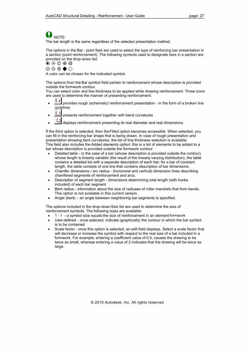
8/20/2019 Autocad Reinforcement Manual Eng
http://slidepdf.com/reader/full/autocad-reinforcement-manual-eng 34/222
AutoCAD Structural Detailing - Reinforcement - User Guide page: 27
NOTE:The bar length is the same regardless of the selected presentation method.
The options in the Bar - point field are used to select the type of reinforcing bar presentation in
a section (point reinforcement). The following symbols used to designate bars in a section areprovided on the drop-down list:
A color can be chosen for the indicated symbol.
The options from the Bar symbol field pertain to reinforcement whose description is providedoutside the formwork contour.You can select color and line thickness to be applied while drawing reinforcement. Three iconsare used to determine the manner of presenting reinforcement:
• provides rough (schematic) reinforcement presentation - in the form of a broken line(polyline)
• presents reinforcement together with bend curvatures
• displays reinforcement presenting its real diameter and real dimensions.
If the third option is selected, then the Filled option becomes accessible. When selected, youcan fill in the reinforcing bar shape that is being drawn. In case of rough presentation andpresentation showing bent curvatures, the list of line thickness selection is available.This field also includes the Added elements option; this is a list of elements to be added to abar whose description is provided outside the formwork contour:
• Detailed table - in the case of a bar (whose description is provided outside the contour),whose length is linearly variable (the result of the linearly-varying distribution), the tablecontains a detailed list with a separate description of each bar; for a bar of constant
length, the table consists of one line that contains description of bar dimensions.• Chamfer dimensions / arc radius - (horizontal and vertical) dimension lines describingchamfered segments of reinforcement and arcs.
• Description of segment length - dimensions determining total length (with hooksincluded) of each bar segment
• Bent radius - information about the size of radiuses of roller mandrels that form bends.This option is not available in this current version.
• Angle (bent) – an angle between neighboring bar segments is specified.
The options included in the drop-down Size list are used to determine the size ofreinforcement symbols. The following sizes are available:
• 1 : 1 - a symbol size equals the size of reinforcement in an element formwork
• User-defined - once selected, indicate (graphically) the contour in which the bar symbol
is to be contained• Scale factor - once this option is selected, an edit field displays. Select a scale factor that
will decrease or increase the symbol with respect to the real size of a bar included in aformwork. For example, entering a coefficient value of 0.5, causes the drawing to betwice as small, whereas entering a value of 2 indicates that the drawing will be twice aslarge.
© 2010 Autodesk, Inc. All rights reserved

8/20/2019 Autocad Reinforcement Manual Eng
http://slidepdf.com/reader/full/autocad-reinforcement-manual-eng 35/222
page: 28 AutoCAD Structural Detailing - Reinforcement - User Guide
2.1.6. Distributions (bars)
This dialog contains options used to present the reinforcing bars belonging to surfacedistributions. Access the dialog by selecting Bars -> Distributions from the Job preferencesdialog. The dialog includes additional options as shown below.
The options located in the Surface distribution field are used to define reinforcing barsbelonging to surface distributions.
The Surface distribution field allows you to:
• Determine a line style used for drawing the top / bottom reinforcement
• Select a color and thickness of the line for distributed reinforcement
• select (the Presentation option) the method of presenting thereinforcement (significant for bars with hook ends).
The options in the Linear distribution field specify the distribution of existing (with the shapealready defined) reinforcement. You can choose a color for presenting reinforcement in thelinear distribution and line thicknesses and style.
If the Mark bar ends option is selected, ends of reinforcing bars in the linear distribution aremarked according to the description style for ends of distributed bars.
2.1.7. Options (bars)
This dialog contains options used to present the reinforcing bar in a cross-section of an RCstructure element. Access the dialog by selecting Bars -> Options from the Job preferencesdialog. The dialog includes additional options as shown below.
© 2010 Autodesk, Inc. All rights reserved

8/20/2019 Autocad Reinforcement Manual Eng
http://slidepdf.com/reader/full/autocad-reinforcement-manual-eng 36/222
AutoCAD Structural Detailing - Reinforcement - User Guide page: 29
Bar size in cross-section:
• Real - if this option is selected, then the real size (in scale) of a bar in cross-section(reinforcing bar diameter) is presented in a drawing
• According to the rule - if this option is selected, then you can choose a size of the bar incross-section, whose diameter is not greater than the reinforcing bar diameter; for
example, if the following size values are chosen: to φ = 18 draw as 25 mm, then all
reinforcing bars in cross-section whose diameters are not greater than 18 mm arepresented as bars of 25 mm diameter.
Below is the Minimum bar length for surface distribution option. You can determine theminimal bar length; a bar whose length is less than this value, and it will not be generatedduring definition of surface distribution. An example situation is displayed in the drawingbelow. Bar no. 1 (diplayed in red), whose length is less than the minimal bar length defined inthe dialog above, will not be generated (considered in tables).
The right part of the dialog contains the Total bar length field; there are the following optionsavailable:
real - if this option is selected, the reinforcingbar length is calculated as exact length of baraxis.
total - if this option is chosen, the reinforcing barlength is calculated as the total of lengths of barsegments with hooks; bar lengths are given incompliance with total outer length.
© 2010 Autodesk, Inc. All rights reserved

8/20/2019 Autocad Reinforcement Manual Eng
http://slidepdf.com/reader/full/autocad-reinforcement-manual-eng 37/222
page: 30 AutoCAD Structural Detailing - Reinforcement - User Guide
Total along axis - if this option is selected, thereinforcing bar length is calculated - inreinforcement tables - as a sum of lengths ofsegments of the bar with hooks; reinforcementtables specify lengths of bars along their axes.
2.1.8. Styles (bars)
This dialog provides basic information about the styles currently defined and relevantreinforcement or table to which these styles apply. Access the dialog by selecting Bars ->Styles from the Job preferences dialog. The dialog includes additional options as shownbelow.
The top part of the dialog includes styles of reinforcement descriptions with reinforcementdivision into categories considered. Once an appropriate reinforcement category is selectedfrom the list (the category is highlighted), an example description displays based on thesettings of the reinforcement description style.
To modify a style:Click Modify. The dialog used for defining styles of reinforcement description opens; itenables direct modification of a selected type of reinforcement.
The bottom part of the dialog displays the table styles applied to prepare a reinforcementtable. Once an appropriate table style is selected, an example reinforcement table for theelement indicated on the list, is displayed. Click Modify to open the dialog used for definingtable styles.
2.1.9. Display (wire fabrics)
Access this option by selecting Wire fabrics -> Display from the Job preferences dialog. Thefollowing dialog displays:
© 2010 Autodesk, Inc. All rights reserved

8/20/2019 Autocad Reinforcement Manual Eng
http://slidepdf.com/reader/full/autocad-reinforcement-manual-eng 38/222
AutoCAD Structural Detailing - Reinforcement - User Guide page: 31
The following options are available in the Wire fabric shape field:
• Color – selection of a color that will be used to draw a wire fabric
• Line thickness – thickness of a line representing a wire fabric in a drawing
• If the Filled option is selected, the wire fabric contour being drawn will be completelyfilled with a selected color.
The End of straight bars option allows you to set the method of presenting bar ends in thedrawing (presentation: without ends, with ends, with ends and description); the option onlyapplies to straight bars without hooks.
The Wire fabric distribution field allows you to determine the style of lines applied to draw top /bottom reinforcement.You can also select the type of wire mesh presentation in drawings (see reinforcementdescription styles – wire fabrics):
• exact
• group
• simplified.
The options in the Wire fabric symbol field refer to reinforcement with a description placedoutside the formwork contour.You can select a color and thickness of a line that will be used to draw a wire fabric. Threebuttons are used to determine the method of reinforcement presentation:
• The first button displays a schematic representation of a wire fabric - in the form of abroken line
• The second button displays a wire fabric with bend curvatures
• The third button displays a wire fabric with a real diameter and real dimensions.If the third button is chosen, the Filled option becomes accessible. You can then fill the drawnshape of a wire fabric with a color. For the schematic presentation and the presentationincluding bend curvatures the list for selection of line thickness is available.This field holds also the Added elements option; this a list of elements that will be appended toa wire fabric presented outside the formwork contour:
• Detailed table – a table including a detailed description of a wire fabric displays
• Chamfer dimensions / arc radius – dimension lines (horizontal and vertical) describingchamfered reinforcement segments and arcs
• Description of segment length – dimensions determining total length of every wire fabricsegment
• Bent radius – in some cases it is necessary to provide information about the size of rollermandrels forming bends – the option is not available.
• Angle (bent) – an angle between the neighboring wire fabric segments is specified.
© 2010 Autodesk, Inc. All rights reserved

8/20/2019 Autocad Reinforcement Manual Eng
http://slidepdf.com/reader/full/autocad-reinforcement-manual-eng 39/222
page: 32 AutoCAD Structural Detailing - Reinforcement - User Guide
The options included in the drop-down Size list are used to determine the size ofreinforcement symbols. The following sizes are available:
• 1 : 1 - it indicates that a symbol size equals the size of a wire fabric in an elementformwork
• User-defined - once this option is selected, you indicate (graphically) the region in whichthe wire fabric symbol is to be contained
• Scale factor - once this option is selected, there appears an edit field. You then specify ascale factor that will decrease or increase the symbol with respect to the real size of awire fabric included in a formwork. For example, entering a factor value of 0.5 results inthe drawing being twice as small, whereas entering a value of 2 - results in the drawingbeing twice as large.
2.1.10. Styles (wire fabrics)
This dialog provides basic information about the styles currently defined and the relevant wirefabric reinforcement or table to which these styles apply. Access the dialog by selecting Wirefabrics -> Styles from the Job preferences dialog. The dialog includes additional options asshown below.
The top part of the dialog includes styles of reinforcement descriptions with division of wirefabric reinforcement into categories considered. Once an appropriate reinforcement categoryis selected from the list (the category is highlighted), an example description displays basedon the settings of the reinforcement description style.
To modify a style:Click Modify. The dialog used for defining styles of reinforcement description opens; itenables direct modification of a selected type of reinforcement.
The bottom part of the dialog displays the table styles applied to prepare a wire fabric
reinforcement table. Once an appropriate table style is selected, an example reinforcementtable for the element indicated on the list, is displayed. Click Modify to open the dialog usedfor defining table styles.
2.1.11. Styles (steel profiles)
This dialog provides basic information about the styles currently defined and relevantreinforcement or table to which these styles apply. Access the dialog by selecting Profiles ->Styles from the Job preferences dialog. The dialog includes additional options as shownbelow.
© 2010 Autodesk, Inc. All rights reserved

8/20/2019 Autocad Reinforcement Manual Eng
http://slidepdf.com/reader/full/autocad-reinforcement-manual-eng 40/222
AutoCAD Structural Detailing - Reinforcement - User Guide page: 33
The top part of the dialog includes styles of steel profile descriptions with reinforcementdivision into categories considered. Once an appropriate reinforcement category is selectedfrom the list (the category is highlighted), an example description displays based on thesettings of the steel profile description style.
To modify a style:Click Modify. The dialog used for defining styles of steel profile description opens; it enablesdirect modification of a selected type of steel profile.
The bottom part of the dialog displays the table styles applied to prepare a steel profile table.Once an appropriate table style is selected, an example steel profile table for the elementindicated on the list, is displayed. Click Modify to open the dialog used for defining tablestyles.
2.1.12. Styles (symbols) After selecting the Symbols -> Styles option from the Job preferences dialog, the followingoptions display:
The dialog displays basic information about the currently-defined styles of symbol description(axis, level and section).The upper part of the dialog includes a description of styles for the following symbols:
• axis symbol,
• elevation mark symbol and
• section symbol.
© 2010 Autodesk, Inc. All rights reserved

8/20/2019 Autocad Reinforcement Manual Eng
http://slidepdf.com/reader/full/autocad-reinforcement-manual-eng 41/222
page: 34 AutoCAD Structural Detailing - Reinforcement - User Guide
After selecting an appropriate style from the list (e.g. the elevation mark symbol – the name ishighlighted), a description example displays based on the settings of the description style.
To modify a style:Click Modify. The dialog used for defining styles for axes, elevation marks or sections opens;it enables direct modification of a selected type of reinforcement.
The bottom part of the dialog displays styles of a summary table. Once an appropriate tablestyle is selected, an example table for the element indicated on the list, is displayed. ClickModify to open the dialog used for defining table styles.
2.2. Preferences
2.2.1. Preferences
Select this option to use the basic parameters of AutoCAD® Structural Detail ing. There aretwo ways to access the option from:
• Menu: Reinforcement / Preferences• Ribbon: ASD - Reinforcement / Settings / Preferences
• Toolbar: Tools / Preferences .
In the AutoCAD® Options dialog, on the Structural Detailing -> General Settings tab you canselect a work template for AutoCAD® Structural Detail ing modules and workspace names(such as ASD or ASD Classic). Templates are located in the CFG folder and contain settingsfor a given country, for example the RBCR-001.dwt file is the template for the USA.
The Structural Detailing tab in the Options dialog is divided into two main parts:
• The left side of the dialog is a selection tree from which you select one of the programpreference options
• To the right of the selection tree are the parameters that correspond to the optionselected from the selection tree; the dialog is updated after selecting an option.
After selecting Reinforcement in the selection tree, the dialog displays the following options:
© 2010 Autodesk, Inc. All rights reserved

8/20/2019 Autocad Reinforcement Manual Eng
http://slidepdf.com/reader/full/autocad-reinforcement-manual-eng 42/222
AutoCAD Structural Detailing - Reinforcement - User Guide page: 35
• Automatic table update - if this option is selected, then while working in the programreinforcement tables will be updated automatically after changes are made in a drawing.
• Reinforcement table for typical structures – enables you to select the method ofgenerating a table for typical structures (column, beam, spread footing, pile cap, pile,etc.); the table may be generated for every element of an RC structure separately(separately for a beam, separately for a column, etc.) or an existing reinforcement tablemay be updated after adding another element of an RC structure.
• Display message warning about identical reinforcement in a drawing – if this option isselected, you are informed about any identical reinforcement.
• Diameter of bent bars presented as – enables you to choose the method of presenting
diameters of bent bars: they are expressed either in selected units (e.g. in mm) or as amultiple of a reinforcing bar diameter.
After selecting the Reinforcement -> Parametrization of descriptions option from the selectiontree, the dialog displays the following options allowing default settings of the way descriptionsof bars and bar distributions will work:
Bar description:
• Description on the extension line option switched off - a bar description is inserted asshown in the drawing below
© 2010 Autodesk, Inc. All rights reserved

8/20/2019 Autocad Reinforcement Manual Eng
http://slidepdf.com/reader/full/autocad-reinforcement-manual-eng 43/222
page: 36 AutoCAD Structural Detailing - Reinforcement - User Guide
• Description on the extension line option switched on - a bar description is inserted asshown in the drawing below
• Extension line option switched off - a bar description is inserted as shown in the drawingbelow (without the line connecting the bar with the label of the position number)
Distribution description:
• Description on the extension line option switched off
• Description on the extension line option switched on
• Extension line option switched off
NOTE: A change of default settings in the above dialog effects the way new descriptions are inserted;descriptions which were defined earlier do not change.
AutoCAD® Structural Detail ing has the following language versions:
USA Poland
UK France
Italy Spain
Russia Germany.
See also:
Job preferences
© 2010 Autodesk, Inc. All rights reserved
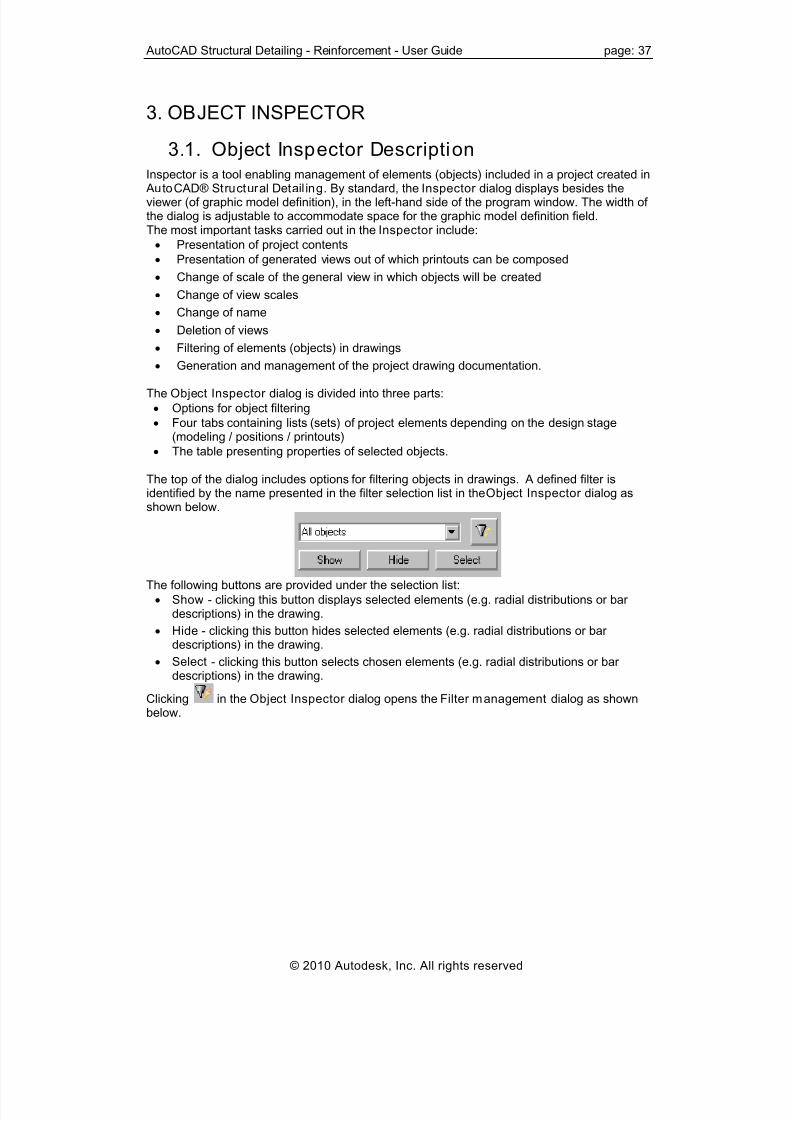
8/20/2019 Autocad Reinforcement Manual Eng
http://slidepdf.com/reader/full/autocad-reinforcement-manual-eng 44/222
AutoCAD Structural Detailing - Reinforcement - User Guide page: 37
3. OBJECT INSPECTOR
3.1. Object Inspector Description
Inspector is a tool enabling management of elements (objects) included in a project created in AutoCAD® Structural Detail ing. By standard, the Inspector dialog displays besides theviewer (of graphic model definition), in the left-hand side of the program window. The width ofthe dialog is adjustable to accommodate space for the graphic model definition field.The most important tasks carried out in the Inspector include:
• Presentation of project contents
• Presentation of generated views out of which printouts can be composed
• Change of scale of the general view in which objects will be created
• Change of view scales
• Change of name
• Deletion of views
• Filtering of elements (objects) in drawings
• Generation and management of the project drawing documentation.
The Object Inspector dialog is divided into three parts:
• Options for object filtering
• Four tabs containing lists (sets) of project elements depending on the design stage(modeling / positions / printouts)
• The table presenting properties of selected objects.
The top of the dialog includes options for filtering objects in drawings. A defined filter isidentified by the name presented in the filter selection list in the Object Inspector dialog asshown below.
The following buttons are provided under the selection list:
• Show - clicking this button displays selected elements (e.g. radial distributions or bardescriptions) in the drawing.
• Hide - clicking this button hides selected elements (e.g. radial distributions or bardescriptions) in the drawing.
• Select - clicking this button selects chosen elements (e.g. radial distributions or bardescriptions) in the drawing.
Clicking in the Object Inspector dialog opens the Filter management dialog as shown
below.
© 2010 Autodesk, Inc. All rights reserved

8/20/2019 Autocad Reinforcement Manual Eng
http://slidepdf.com/reader/full/autocad-reinforcement-manual-eng 45/222
page: 38 AutoCAD Structural Detailing - Reinforcement - User Guide
The dialog includes all defined filters and the following buttons:
• Show, Hide, Select - they work the same as in the Object Inspector dialog (see thedescription above)
• Unselect - clicking this button switches off selection of chosen elements (e.g. radialdistributions or bar descriptions) in the drawing.
• Select All / Unselect A ll - clicking this button selects / switches off selection of allelements (filters) provided on the list
• New, Edi t, Delete – these options are not available in the current program version.
3.2. Model
The Model tab provides a list of defined elements (levels, groups of elements as well aselements belonging to levels and groups) that describe the division of reinforcing bars intostructural elements such as a beam, a column, a spread footing, etc. A structure of user-defined levels, groups and elements is shown in the form of a tree is shown below.
© 2010 Autodesk, Inc. All rights reserved
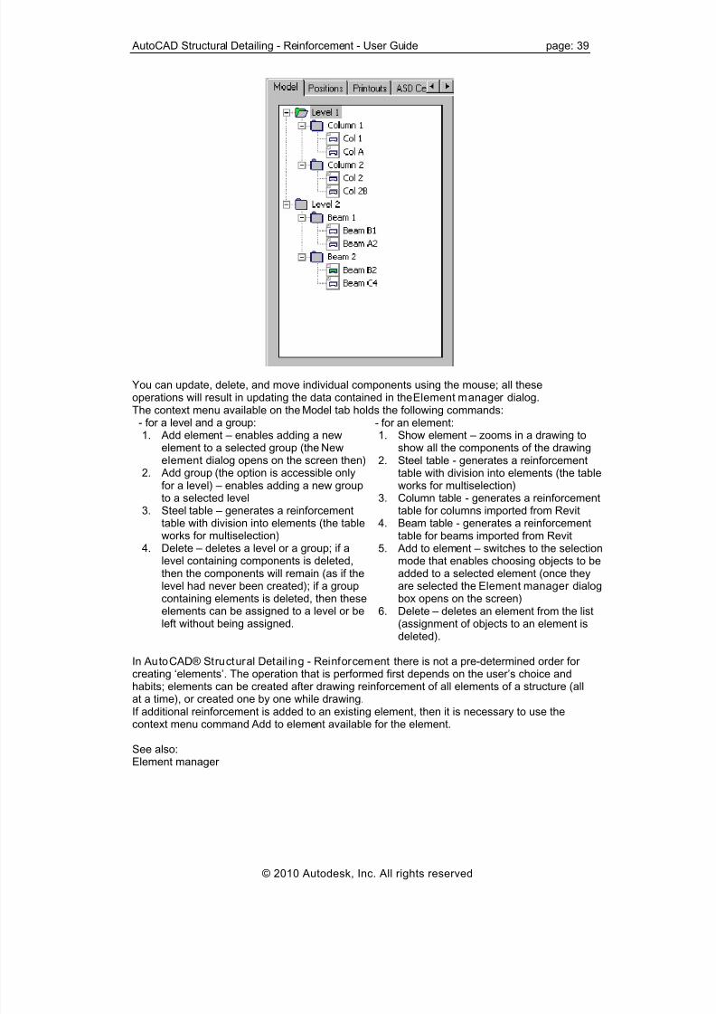
8/20/2019 Autocad Reinforcement Manual Eng
http://slidepdf.com/reader/full/autocad-reinforcement-manual-eng 46/222
AutoCAD Structural Detailing - Reinforcement - User Guide page: 39
You can update, delete, and move individual components using the mouse; all theseoperations will result in updating the data contained in the Element manager dialog.The context menu available on the Model tab holds the following commands:
- for a level and a group:1. Add element – enables adding a new
element to a selected group (the Newelement dialog opens on the screen then)
2. Add group (the option is accessible only
for a level) – enables adding a new groupto a selected level
3. Steel table – generates a reinforcementtable with division into elements (the tableworks for multiselection)
4. Delete – deletes a level or a group; if alevel containing components is deleted,then the components will remain (as if thelevel had never been created); if a groupcontaining elements is deleted, then theseelements can be assigned to a level or beleft without being assigned.
- for an element:1. Show element – zooms in a drawing to
show all the components of the drawing2. Steel table - generates a reinforcement
table with division into elements (the table
works for multiselection)3. Column table - generates a reinforcement
table for columns imported from Revit4. Beam table - generates a reinforcement
table for beams imported from Revit5. Add to element – switches to the selection
mode that enables choosing objects to beadded to a selected element (once theyare selected the Element manager dialogbox opens on the screen)
6. Delete – deletes an element from the list(assignment of objects to an element isdeleted).
In AutoCAD® Structural Detail ing - Reinforcement there is not a pre-determined order forcreating ‘elements’. The operation that is performed first depends on the user’s choice andhabits; elements can be created after drawing reinforcement of all elements of a structure (allat a time), or created one by one while drawing.If additional reinforcement is added to an existing element, then it is necessary to use thecontext menu command Add to element available for the element.
See also:Element manager
© 2010 Autodesk, Inc. All rights reserved

8/20/2019 Autocad Reinforcement Manual Eng
http://slidepdf.com/reader/full/autocad-reinforcement-manual-eng 47/222
page: 40 AutoCAD Structural Detailing - Reinforcement - User Guide
3.3. Positions
The Positions tab presents a list of defined views containing name, scale and name of theprintout layout including a given view as shown below.
The icon of a document included on the list is presented as follows:
• - the document has been read from Autodesk Robot Structural Analysis .
• in yellow - the document is active on the edition layout; moreover, there may existviews for a document, presented as:
– active view
– inactive view.If the icon of a view provided on the list is shown in bold, it means that it is an active view. Access the context menu by right-clicking the Positions tab. The menu contains severaloptions which allow performing operations on selected positions:
• Change name - choosing this command enables changing the name of a highlightedview (the name is entered to the command line)
• Activate - choosing this command activates the selected drawing
• Add to current printout - selecting this command adds a view with selected drawing to thecurrent printout
• Add to current printout as block - selecting this command adds a view with selecteddrawing in form of block to the current printout. Arranging printouts by means of the blocks enables to create printout layouts with a largenumber of elements. It is possible to modify the elements presented in a block on amodel only and the modification will be updated after moving on to the drawing area. It isnot possible to modify elements by the means of the block edition.
• Show view - this option allows for presentation of the selected view
• Delete view - choosing this command enables deletion of the created view.
© 2010 Autodesk, Inc. All rights reserved

8/20/2019 Autocad Reinforcement Manual Eng
http://slidepdf.com/reader/full/autocad-reinforcement-manual-eng 48/222
AutoCAD Structural Detailing - Reinforcement - User Guide page: 41
3.4. Structural Detailing Center
This Structural Detailing Center tab enables copying settings (styles) between projects.
Click the File button and select a file with an earlier-saved project, the Inspector dialogdisplays all the defined styles that may be used in the current project. After highlighting a selected style, right-click the Add command, to add the style to the stylesavailable in the current project.
3.5. Printouts
The Printouts tab enables management of printouts in AutoCAD® Structural Detail ing; itpresents the list of all printouts defined in the AutoCAD® Structural Detail ing project.Printouts are presented together with a set of views. The printout list contains all the printouts,even those which do not include any views. The structure of user-defined printouts and viewsis shown in a form of a tree. Due to logical reasons, views are placed in a printout, however,for the user’s convenience, the tree also includes an intermediate level, so that it is obvious towhich document given views belong. If the printout layout is active, then the icon of a printoutcorresponding to the active printout layout is presented in red color.Printouts provided on the list are selected by selecting them (take note that only elements ofone printout may be selected at a time - it is impossible to select elements of two differentprintouts). Selection of the printout in the dialog is synchronized with the graphic editor - anappropriate drawing displays on the screen. Access the context menu by right-clicking the Printouts tab. The menu contains severaloptions for performing operations on selected printouts:
• Change name - choosing this command enables changing the name of a highlightedprintout (the name is entered to the command line)
• Delete - choosing this command results in removal of selected printouts from a project• Activate - choosing this command causes the highlighted printout to become active(visible)
© 2010 Autodesk, Inc. All rights reserved

8/20/2019 Autocad Reinforcement Manual Eng
http://slidepdf.com/reader/full/autocad-reinforcement-manual-eng 49/222
page: 42 AutoCAD Structural Detailing - Reinforcement - User Guide
• Unload printout - choosing this command causes the selected printout to be excludedfrom the list of available printouts
• Save printout - choosing this command enables saving the selected printout as a *.dwgfile
• Save all printouts - choosing this command enables saving all the printouts in a *.dwg file
• Add printout - selecting this command adds an empty printout to the project (the name is
entered to the command line).
4. TYPICAL STRUCTURES
4.1. Reinforcement / formwork of typical RCstructure elements
Use this option to define typical RC structure elements and their reinforcement. There arethree ways to access this option from:
• Menu: select one of the options available in the submenu Reinforcement / Structureelements - reinforcement
• Ribbon: select one of the options available in the panel ASD Structure elements /Structure elements - reinforcement
• Toolbar: click the appropriate icon in the bar Structure elements - reinforcement
• Command line: RBCT_MACRO.
Typical structures are grouped into certain categories. When choosing a structure, find anappropriate category. The current version of AutoCAD® Structural Detail ing -Reinforcement offers access to the following databases (macros) to define geometry /reinforcement of RC structure elements:
• Spread footing
• Sleeve footing
• Continuous footing• Column
• Beam
• Opening
• Corner
• Slab corner
• Distribution of prefabricated slabs
• Stairs
• Pile cap (pile foundation)
• Pile
• Ground beam
• Parapet
• Retaining wall• Additional connecting elements
• Linear element.
The macros listed are available from the menu (Reinforcement / Structure elements –reinforcement), ribbon (ASD Structure elements / Structure elements – reinforcement) and inthe toolbar (Structure elements – reinforcement):
∗ Spread footing -
∗ Sleeve footing -
∗ Continuous footing -
© 2010 Autodesk, Inc. All rights reserved

8/20/2019 Autocad Reinforcement Manual Eng
http://slidepdf.com/reader/full/autocad-reinforcement-manual-eng 50/222
AutoCAD Structural Detailing - Reinforcement - User Guide page: 43
∗ Column -
∗ Beam -
∗ Opening -
∗ Corner -
∗ Slab corner -
∗ Distribution of prefabricated slabs -
∗ Stairs -
∗ Pile cap (pile foundation) -
∗ Pile -
∗ Ground beam -
∗ Parapet -
∗ Retaining wall -
∗ Linear element consisting of two options:
Create linear element – the option defines an RC structure element (section of anRC element) that is assigned element length; such an element may be saved to the
database
Insert linear element - the option inserts an RC structure element (section of an RCelement) that has been assigned length; after selecting a linear element, a block ofdrawing elements is placed in a drawing – a selected linear element is assigned a nameand length.
The categories of typical structures are configured within a given model. After selecting acategory, an additional dialog displays in which you can specify parameters of a selectedelement of an RC structure. The shape of this dialog depends on a structure categoryelected.s
In the Formworks menu (Reinforcement / Structure elements - formworks), ribbon (ASD
Structure elements / Structure elements - formworks) and in the toolbar (Structure elements –formworks) the following macros for formworks of RC structure elements are available:
• Spread footing -
• Sleeve footing -
• Continuous footing -
• Column -
• Beam -
• Stairs -
© 2010 Autodesk, Inc. All rights reserved

8/20/2019 Autocad Reinforcement Manual Eng
http://slidepdf.com/reader/full/autocad-reinforcement-manual-eng 51/222
page: 44 AutoCAD Structural Detailing - Reinforcement - User Guide
• Pile cap (pile foundation) -
• Ground beam -
• Retaining wall -
• Parapet -
• Additional connecting elements - .
5. RULES APPLIED WHILE DEFININGREINFORCEMENT
5.1. Location of a reinforcing bar in a drawingThe following principle applies when determining the position of a reinforcing bar in a drawing:Bar location depends on a direction of point definition. The principle that holds when defining areinforcing bar consists in determining the order of points clockwise (along the EXTERNALpart of an object). The defined bar are positioned in the inner part of an object. In the case of abar with hooks of a bending angle greater than zero degrees, the hooks are located on theopposite side with respect to the side where points defining the bar length are placed, thusthey will be turned towards the middle of an object. An example of a reinforcing bar in adrawing is shown below.
Bar defined from right to left:
1 - Beginning of a reinforcing bar2 - End of a reinforcing bar
Bar defined from left to right :1 - Beginning of a reinforcing bar2 - End of a reinforcing bar
5.2. Angle of hook bending
The following principle applies when determining a value of the angle of hook bending:The angle of hook bending is an angle by which a reinforcing angle should be bent toobtain a hook. An example of hook bending (with the angle set to 135 degrees) is shownbelow.
© 2010 Autodesk, Inc. All rights reserved

8/20/2019 Autocad Reinforcement Manual Eng
http://slidepdf.com/reader/full/autocad-reinforcement-manual-eng 52/222
AutoCAD Structural Detailing - Reinforcement - User Guide page: 45
6. DEFINITION OF REINFORCEMENT - LONGITUDINALREINFORCEMENT
6.1. DEFINITION OF BAR REINFORCEMENT - bar
elevation (longitudinal reinforcement)This option is used define the reinforcing bars (longitudinal reinforcement) in an element of RCstructure. There are three ways to access this option from:
• Menu: Reinforcement / Reinforcement - elevation
• Ribbon: ASD - Reinforcement / Reinforcement - definition / Reinforcement - elevation
• Toolbar: Bars - definition / Reinforcement - elevation
• Command line: RBCR_DEF_BAR_BV.
Once the Reinforcement - elevation option is selected, the dialog used to select a shape oflongitudinal reinforcement displays as shown (NOTE: while reinforcement is being defined thisdialog remains visible).
The Reinforcement - elevation dialog can be split into three parts:
• The left side of the dialog displays basic information concerning reinforcement: diameter,cover and steel grade adopted from preference settings
• The middle of the dialog displays the icons that symbolize basic shapes of longitudinalreinforcement and allow selection of the reinforcement type; once a longitudinalreinforcement type is selected, contents of the field with parameters of a reinforcementshape changes
• The right side of the dialog displays several icons used to select the mode of graphicaldefinition of reinforcement; if they are selected, the mode of graphic interface is selectedaccording to the specific manner of contour definition. NOTE: bars can only be definedafter one of these icons is selected.
The dialog opens and displays the longitudinal reinforcement type defined with the selectedparameters.
(located in the bottom right corner) is used to inherit (adopt) parameters from thereinforcement already defined. It is the standard tool provided in most dialogs.
The following types of longitudinal reinforcement are available:
• straight bar
• straight bar with bar anchor generation
• bent bar - type 1
• bent bar - type 2
• bar from database
• bar of any shape.
© 2010 Autodesk, Inc. All rights reserved

8/20/2019 Autocad Reinforcement Manual Eng
http://slidepdf.com/reader/full/autocad-reinforcement-manual-eng 53/222
page: 46 AutoCAD Structural Detailing - Reinforcement - User Guide
Once you define the reinforcement shape, the Reinforcement description dialog displays. Youcan then select the elements of reinforcement.
Reinforcing bars are also defined by means of the commands available.
See also:
Example of definition of longitudinal reinforcement
6.2. Straight bar
This option is used to define a straight bar. Access this option by clicking . The followingdialog displays:
To define a bar, specify the following from the dialog:
• Bar diameter (the most recent diameter for this reinforcement type is adopted by default)
• Cover of a reinforcing bar (the most recent cover defined for this reinforcement type isadopted by default)
• In the Parameters of reinforcing bar shape field - parameters of bar ending with hooks,i.e., a hook angle and length (the hook length defined in the dialog denotes a length of
the straight segment of a hook or its real length - see Options in the Job Preferencesdialog). You can lock a hook length by selecting the option next to the edit field for
defining a hook length (√ appears); the edit field becomes inaccessible. If you modifyparameters (length or diameter) of a bar with locked hook length, the hook length doesnot change.
The list of standard hook angle values: (see: method of measuring the angle of bar bending):
⇒ 0° ⇒ 90° ⇒ 135° ⇒ 180° ⇒ -90°
⇒ -135° ⇒ -180°.
When defining the straight bar, only (2 Points) is available (the remaining icons areunavailable); indicate the two bar points, and click to start the definition.
NOTE:Bar location depends on the direction of point definition. The principle that applies whiledefining a reinforcing bar includes determining the order of points clockwise (along theEXTERNAL part of an object). The defined bar will always be positioned in the inner part of anobject. In the case of bar with hooks with a bending angle greater than zero degrees, thehooks will always be positioned on the side opposite to the side where points defining the bar
length are placed, thus they will be turned towards the middle of an object.
© 2010 Autodesk, Inc. All rights reserved

8/20/2019 Autocad Reinforcement Manual Eng
http://slidepdf.com/reader/full/autocad-reinforcement-manual-eng 54/222
AutoCAD Structural Detailing - Reinforcement - User Guide page: 47
After defining the first point determining the bar position, the bar length changes depending onthe cursor position.
See also:Commands from the command line - definition of longitudinal reinforcement
6.3. Definition of a straight bar (longitudinalreinforcement)
To define a straight bar, from the the Reinforcement - elevation dialog:
• Define the following information for the reinforcing bar: diameter, cover as well asparameters of bar ending with hooks (hook angle and length).
• Click (2 Points), located on the right side of the dialog.
• Determine the bar point beginning and end positions.
See also:Method of measuring the angle of bar bending
Location of a reinforcing bar in a drawing
6.4. Straight bar with anchor element
Click , the following dialog displays:
To define a bar, specifiy the following from the dialog:
• Bar diameter (the most recent diameter for this reinforcement type is adopted by default)
• Cover of reinforcing bars (the most recent cover defined for this reinforcement type isadopted by default)
• In the Parameters of reinforcing bar shape field - parameters of anchors f or reinforcingbar ends (anchor length or an anchor ended with a hook). You can lock a hook length by
selecting the option next to the edit field for the hook length (√ appears); the edit field
becomes inaccessible. If you modify parameters (length or diameter) of a bar with alocked hook length, the hook length does not change.
For an anchored bar, the default setting defines the anchor for a straight segment of a bar(hook angle equals zero). You may also define an anchor for a bar with hook of a specifiedbending angle. Thus three choices are available:
1anchor:
α = 0
l ≠ 0
2
hook:
α ≠ 0 (by default, the value of 135degrees is adopted)l = 0
© 2010 Autodesk, Inc. All rights reserved

8/20/2019 Autocad Reinforcement Manual Eng
http://slidepdf.com/reader/full/autocad-reinforcement-manual-eng 55/222
page: 48 AutoCAD Structural Detailing - Reinforcement - User Guide
3anchor ended with a hook:
α ≠ 0
l ≠ 0
The list of standard hook angle values is presented below (see: method of measuring the
angle of bar bending):⇒ 0° ⇒ 90° ⇒ 135° ⇒ 180° ⇒ -90° ⇒ -135° ⇒ -180°.
While a straight bar is being defined, only (2 Points) is available (the remaining icons areunavailable); indicate the two bar points, and click to start the definition.
NOTE:The bar location depends on the direction of point definition. The principle that applies whiledefining a reinforcing bar includes the order of points clockwise (along the EXTERNAL part ofan object). The defined bar will always be positioned in the inner part of an object. In the caseof bar with hooks with bending angle greater than zero degrees, the hooks will always bepositioned on the side opposite to the side where points defining the bar length are placed,thus they will be turned towards the middle of an object.
After defining the first point determining the bar position, the bar length changes depending onthe cursor position.
See also:
Commands from the command line - definition of longitudinal reinforcement
6.5. Definition of a straight bar with anchors(longitudinal reinforcement)
To define a straight bar with an anchor, from the Reinforcement - elevation dialog:
• Determine the following information (concerning the reinforcing bar): diameter, cover,parameters of bar ending with hooks, i.e., hook angle and length.
• Select the anchor type (only anchor or anchor and/or hook).
• Click (2 Points), on the right side of the dialog.
• Determine the bar points beginning and end positions.
See also:Method of measuring the angle of bar bendingLocation of a reinforcing bar in a drawing
© 2010 Autodesk, Inc. All rights reserved

8/20/2019 Autocad Reinforcement Manual Eng
http://slidepdf.com/reader/full/autocad-reinforcement-manual-eng 56/222
AutoCAD Structural Detailing - Reinforcement - User Guide page: 49
6.6. Bent bar - type 1
This option is used to define a bent bar. Acess this option by clicking . The following dialogdisplays:
To define a bar, specify the following from the dialog:
• Bar diameter (the most recent diameter for this reinforcement type is adopted by default)• Cover of a reinforcing bar (the most recent cover defined for this reinforcement type isadopted by default)
• In the Parameters of reinforcing bar shape field - parameters of anchors for reinforcingbar ends, i.e. hook angle and length. You can lock a hook length by selecting the option
next to the edit field for defining a hook length (√ appears); the edit field becomesinaccessible. If you modify parameters (length or diameter) of a bar with locked hooklength, the hook length does not change.
When defining the bent bar, it is important to determine the bar orientation. The default valueof the inclination angle for a bent part in a longitudinal bar is 45 degrees. On the selection listother values of inclination angle are also available: 30, 45, 60 degrees.Bar orientation (numbers shown in the drawing denote points defining a bar: 1 - beginning of
a reinforcing bar , 2 - end of a reinforcing bar ):
1. Beginning point of a bar is located onthe right side
2. Beginning point of a bar is located onthe left side
For a definition of a bent bar, only (Diagonal) is available (the remaining icons areunavailable). After defining a first point determining the bar position, bar length and height changedepending on the cursor position. Once a second point is indicated, then the mode changes todefinition of a position of the oblique reinforcement segment; determine the position of theoblique branch point with respect to which the position of the oblique bar part is determined.Move the cursor to display the distances between the indicated point and the bar end.
See also:Commands from the command line - definition of longitudinal reinforcement
© 2010 Autodesk, Inc. All rights reserved

8/20/2019 Autocad Reinforcement Manual Eng
http://slidepdf.com/reader/full/autocad-reinforcement-manual-eng 57/222
page: 50 AutoCAD Structural Detailing - Reinforcement - User Guide
6.7. Definition of a bent bar (type 1) - longitudinalreinforcement
To define a bent bar, from the Reinforcement - elevation dialog:
• Determine the following information (concerning the reinforcing bar): diameter, cover,
parameters of a bent bar ending with hooks, i.e. hook angle and length at the beginningand end of a reinforcing bar.
• Determine the angle of the bar bending (the following values of a bending angle areavailable: 30, 45 and 60 degrees).
• Click (Diagonal), on the right side of the dialog.
• Determine the bar points beginning and end positions.
• Determine the length (position) of the bent part of a reinforcing bar.
See also:Method of measuring an angle of bar bendingLocation of a reinforcing bar in a drawing
6.8. Bent bar - type 2
How to define a bent bar
This option is used to define a bent bar – type 2. Access this option by clicking . Thefollowing dialog displays:
To define a bar, specify the following from the dialog:
• Bar diameter (the most recent diameter for this reinforcement type is adopted by default)
• Cover of a reinforcing bar (the most recent cover defined for this reinforcement type isadopted by default)
• In the Parameters of reinforcing bar shape field - parameters of anchors for reinforcingbar ends, i.e. hook angle and length. You can lock a hook length by selecting the option
next to the edit field for defining a hook length (√ appears); the edit field becomes
inaccessible. If you modify parameters (length or diameter) of a bar with locked hooklength, the hook length does not change.
When defining a bar, it is important to determine the bar orientation. The default value of theinclination angle for a bent part in a longitudinal bar is 45 degrees. On the selection list othervalues of inclination angle are also available: 30, 45, 60 degrees.
Bar orientation (numbers shown in the drawing denote points defining a bar: 1 - beginning ofa reinforcing bar , 2 - end of a reinforcing bar ):
1. Beginning point of a bar is located onthe right side
© 2010 Autodesk, Inc. All rights reserved

8/20/2019 Autocad Reinforcement Manual Eng
http://slidepdf.com/reader/full/autocad-reinforcement-manual-eng 58/222
AutoCAD Structural Detailing - Reinforcement - User Guide page: 51
2. Beginning point of a bar is located onthe left side
For a definition of a bent bar only (Diagonal) is available (the remaining icons are
unavailable). After defining a first point determining the bar position, bar length and height changedepending on the cursor position. Once a second point is indicated, then the mode changes todefinition of a position of the oblique reinforcement segment; determine the position of theoblique branch point with respect to which the position of the oblique bar part will bedetermined. Move the cursor to display the distances between the indicated point and the barend.
The above operation is performed for a second oblique segment of reinforcement.
See also:Commands from the command line - definition of longitudinal reinforcement
6.9. Bar from database
Click , the following dialog displays:
NOTE:Bar shapes are used to define a bar and to assign an appropriate identification code to it.
In the Shape parameters field the following options are provided:
• Schematic drawing of the reinforcement shape.
• Edit fields where hook parameters are determined (hooks are ascribed permanently tothe shape from database). You can lock a hook length by selecting the option next to the
edit field for defining a hook length (√ appears); the edit field becomes inaccessible. Ifyou modify parameters (length or diameter) of a bar with locked hook length, the hooklength does not change.
• Selection list containing codes - they affect bending diameters (French code)
• Two buttons: Shape database and Shape parameters.On the right side of the dialog, only the Points icon is available. When selected, the definitionof a bar from the database begins. The remaining icons are unavailable.
After clicking the Shape database… button, the Bar database dialog opens.
NOTE:The database of reinforcing bar shapes and corresponding shape codes depend on a selected
code of RC structure design.
© 2010 Autodesk, Inc. All rights reserved
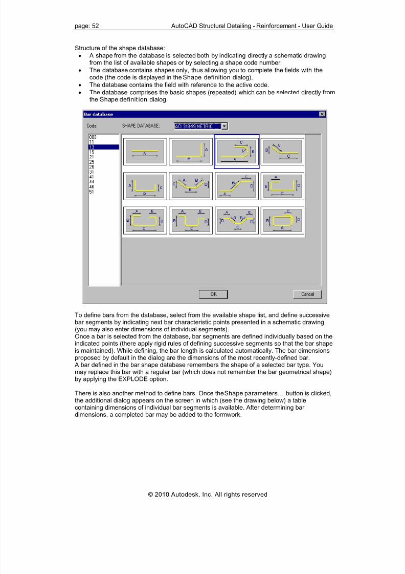
8/20/2019 Autocad Reinforcement Manual Eng
http://slidepdf.com/reader/full/autocad-reinforcement-manual-eng 59/222
page: 52 AutoCAD Structural Detailing - Reinforcement - User Guide
Structure of the shape database:
• A shape from the database is selected both by indicating directly a schematic drawingfrom the list of available shapes or by selecting a shape code number.
• The database contains shapes only, thus allowing you to complete the fields with thecode (the code is displayed in the Shape definition dialog).
• The database contains the field with reference to the active code.
• The database comprises the basic shapes (repeated) which can be selected directly fromthe Shape definit ion dialog.
To define bars from the database, select from the available shape list, and define successivebar segments by indicating next bar characteristic points presented in a schematic drawing(you may also enter dimensions of individual segments).Once a bar is selected from the database, bar segments are defined individually based on theindicated points (there apply rigid rules of defining successive segments so that the bar shapeis maintained). While defining, the bar length is calculated automatically. The bar dimensionsproposed by default in the dialog are the dimensions of the most recently-defined bar.
A bar defined in the bar shape database remembers the shape of a selected bar type. Youmay replace this bar with a regular bar (which does not remember the bar geometrical shape)by applying the EXPLODE option.
There is also another method to define bars. Once the Shape parameters… button is clicked,the additional dialog appears on the screen in which (see the drawing below) a tablecontaining dimensions of individual bar segments is available. After determining bardimensions, a completed bar may be added to the formwork.
© 2010 Autodesk, Inc. All rights reserved

8/20/2019 Autocad Reinforcement Manual Eng
http://slidepdf.com/reader/full/autocad-reinforcement-manual-eng 60/222
AutoCAD Structural Detailing - Reinforcement - User Guide page: 53
The above dialog contains a table that displays dimensions of bar segments. If the dialog isopen while a bar is being defined, then dimensions that are not yet defined are assigned azero value. You can change the bar segment lengths and to complete the missing dimensions.The field with a shape code is filled out automatically depending on a typical shape selected.
Both modes of reinforcement definitions are synchronized with each other. Both definitionmodes can be used alternately.
See also:Commands from the command line - definition of longitudinal reinforcement
6.10. Arbitrary shape of a bar
This option is used to define an arbitrary shape of a bar. Access this option by clicking .
The following dialog displays:
You can select a type of hook at the beginning and end of the defined reinforcement and lock
a hook length by selecting the option next to the edit field for defining a hook length (√ appears); the edit field becomes inaccessible. If you modify parameters (length or diameter) ofa bar with a locked hook length, the hook length does not change.Define the successive characteristic points with the cursor. On these points the transversalreinforcement of any shape will be based. When defining a bar graphically, it is possible tochange its location with respect to the insertion points (formwork), a value of the bar cover anda location of hooks.The field with a shape code is filled out (a unique code of the bar shape should be enteredthere). This code is presented in the reinforcement table; it will be also included in theinformation about the bar.
While generating reinforcement, bent radiuses will be drawn automatically on the basis of theconditions determined in a selected code. This information is provided in the bar database.
© 2010 Autodesk, Inc. All rights reserved

8/20/2019 Autocad Reinforcement Manual Eng
http://slidepdf.com/reader/full/autocad-reinforcement-manual-eng 61/222
page: 54 AutoCAD Structural Detailing - Reinforcement - User Guide
The following icons are active for bar definition:
Points
Select - it enables changing indicated arcs and open polylines to a reinforcing bar.The remaining icons are unavailable.See also:
Commands from the command line - definition of longitudinal reinforcement
6.11. Reinforcement description
This option is used to enable the final selection of a reinforcement description.The following dialog displays:
NOTE:
If you click (Modify reinforcement description), two additional options are available:
• Description style (used to modify a description style of the reinforcement chosen),
• and the Details button, which when clicked, opens the dialog used for modifying a
style of reinforcement description (shape).
The options provided in this dialog enable final selection of a reinforcement description. It canbe performed by switching off active variables initialized based on the syntax defined.
Notes:
• A reinforcement shape can be described only for a single position, in other words, two ormore bars cannot be described simultaneously.
• The Number edit field allows you to enter an ultimate number of reinforcing bars that areused directly in the reinforcement summary tables.The amount of reinforcement specified during bar definition is a superior quantity withrespect to the amount resulting from the subsequent distribution of this bar and thatreinforcement amount is provided in the table; the number of bars may be represented as
an equation, e.g. 2*(8+4);• In the Spacing edit field, you may enter spacing values, despite reinforcement distribution
not being defined yet. This field is editable on condition that the "%spa" variable iscontained in the style of reinforcement description. It is only a static parameter thatserves informative purposes and may be applied in reinforcement tables which includethe spacing parameter. However, it should be remembered that if you have entered aspacing value in this field, then regardless of real values of bar spacing in the structureelement, the value provided in the dialog will be assumed in the table.
• If the Active option is selected, it results in including the reinforcement being described inthe reinforcement table. Reinforcement that is described for the first time will be active.When the same reinforcement is described twice, the option will be switched off on itsown. It is possible to prevent (when describing the same reinforcement twice) the numberof reinforcing bars calculated when preparing a bar table to be doubled; description ofactive and not active reinforcement may differ in a generated drawing – the options usedfor this purpose are provided in the Description of reinforcement shape dialog.
© 2010 Autodesk, Inc. All rights reserved

8/20/2019 Autocad Reinforcement Manual Eng
http://slidepdf.com/reader/full/autocad-reinforcement-manual-eng 62/222
AutoCAD Structural Detailing - Reinforcement - User Guide page: 55
• User description in the drawing and User description in the table fields are used to addany text to a reinforcement description; the description is presented in drawings (includedin bar descriptions in the drawing) and in the table (included only in the reinforcementtable); the added text will be remembered (on the selection list) and you will be able touse it later; text taken from the library of standard descriptions may also be applied.These descriptions assume the style of the text describing the reinforcement. The user
description is presented on the screen in several lines; then the mechanisms accessiblein the AutoCAD® program are applied. A user description together with an extension lineand label make up one object. Such an object may be edited (translation, rotation); byclicking the EXPLODE option.
• A style of reinforcement description is chosen from the Description style selection list; thelist contains all description styles defined for that type of reinforcement (the first on theselection list is a default description style chosen in the Descript ion of reinforcementshape dialog); before a reinforcement description is inserted in a drawing, parameters ofthe description style can be changed; pressing the Details... button opens theReinforcement description dialog where modifications of the style can be made(NOTE: modifications of the description style refer only to that one reinforcementdescription).
NOTE:Whether any of the options listed above are selected depends on the defined descriptionsyntax that is available in styles of reinforcement description. If for example, a bar symbol is tobe included in the bar description, you should open the Descript ion of reinforcement shapedialog, select reinforcement description (e.g. Bar shape), click Modify, switch on theReinforcement symbol option provided on the Description syntax tab, click the button with thearrow; the variable containing a bar symbol will be added in the Description edit field; to endthe operation, click Add.
6.12. User description - AutoCAD program
mechanismsWhile defining a user description, you can apply formatting by introducing format codes, i.e.the mechanisms available in AutoCAD®. To apply formatting, format codes presented in thetable below should be used.Format codes for paragraphsFormat code Purpose \0...\o Turns overline on and off\L...\l Turns underline on and off\~ Inserts a nonbreaking space\\ Inserts a backslash\{...\} Inserts an opening and closing brace\Cvalue; Changes to the specified color
\File name; Changes to the specified font file\Hvalue; Changes to the text height specified in drawing units\Hvaluex; Changes the text height to a multiple of the current text height\S...^...; Stacks the subsequent text at the \, # or ^ symbol\Tvalue; Adjusts the space between characters, from .75 to 4 times\Qangle; Changes obliquing angle\Wvalue; Changes width factor to produce wide text\A Sets the alignment value; valid values: 0, 1, 2 (bottom, center, top)\P Ends paragraph
Multiline text objects use word wrap to break long lines into paragraphs. For AutoCAD to breaklines automatically and not to create a new paragraph, the line should end with either abackslash (\) or a space character.
© 2010 Autodesk, Inc. All rights reserved

8/20/2019 Autocad Reinforcement Manual Eng
http://slidepdf.com/reader/full/autocad-reinforcement-manual-eng 63/222
page: 56 AutoCAD Structural Detailing - Reinforcement - User Guide
6.13. Commands from the command line - defini tionof longitudinal reinforcement
The following parameters can be specified in the command line while defining a longitudinalbar:
Bar diameter or [Cover / Bar type / Define ] <12>: 16Select option [Diameter / Cover / Bar type / Define ] <Define>:Reinforcement diameter <12>:Cover <5.5> : 6Bar type: [Straight / Anchored / 1bent / 2bent / Base / Any ] <Straight>:
For straight and anchored bar the following parameters are defined:Beginning pointEnd point or [Side]where:Side - it determines a change of a bar position with respect to the formwork line (with hooksincluded)
For bent bars the following parameters are defined:First cornerSecond cornerSegment location or [Back]:
For bars from database the following parameters are defined:Bar code or [Select from database]Beginning pointNext point or [Side / Cover / Mirror / Back]where:beginning point - first point determining shape of a bar (bar beginning)next point - next points determining shape of a barside - determines on which side of a cross section contour of an RC element the current
segment of reinforcement is to be located (change of a bar position with respect to the line -points of definition to the opposite one)cover - value of a cover for the current segment of reinforcementmirror - determines the mirror reflection of the current reinforcement segmentback - cancels the last command.
For bar of arbitrary shape the following parameters are defined:Beginning pointNext point or [Side / Cover / 1hook / 2hook / Back]Cover <6>: 7where:beginning point - first point determining shape of a bar (bar beginning)next point - next points determining shape of a bar
side - determines on which side of a cross section contour of an RC element the currentsegment of reinforcement is to be locatedcover - value of a cover for the current segment of reinforcement1 hook - direction of hook bending2 hook - direction of hook bending (opposite to hook 1)back - cancels the last command.
© 2010 Autodesk, Inc. All rights reserved

8/20/2019 Autocad Reinforcement Manual Eng
http://slidepdf.com/reader/full/autocad-reinforcement-manual-eng 64/222
AutoCAD Structural Detailing - Reinforcement - User Guide page: 57
6.14. Example of definition of longitudinalreinforcement
This option is used to define longitudinal reinforcement of the RC beam.
The following dialog displays:
To define longitudinal reinforcement of the RC beam, follow the steps below:
DEFINITION OF THE BEAM FORMWORK
1. Click the option 2. In the Formworks – Beam dialog specify the following parameters:
- Section type: 1 (rectangular)- Beam type: 1 (single-span beam)- Dimensions of the beam cross section: height = 600 mm, width = 300 mm- Beam geometry as shown in the drawing below
3. Click Insert, and indicate the location of the beam formwork in the drawing
DEFINITION OF THE BEAM REINFORCEMENT
1. Click the Reinforcement - elevation option2. In the Reinforcement – elevation dialog, specify the following parameters:
• Type of reinforcing bars: straight bar
• Bar diameter: 12 mm; cover of reinforcing bars: 30 mm
• Steel grade: R
• Shape parameters as shown in the drawing below
© 2010 Autodesk, Inc. All rights reserved

8/20/2019 Autocad Reinforcement Manual Eng
http://slidepdf.com/reader/full/autocad-reinforcement-manual-eng 65/222
page: 58 AutoCAD Structural Detailing - Reinforcement - User Guide
3. Click (2 Points), located in the right-hand side of the dialog.4. In the drawing of the beam formwork, indicate point 1 and point 2 (see the drawing at
the beginning of the example).5. Accept the deafult reinforcement description proposed in the Reinforcement
description dialog by clicking OK.6. Indicate the position of the reinforcement description in the drawing by clicking Enter
or right-clicking Enter from the context menu.
7. Click the Reinforcement - elevation option again.8. In the Reinforcement – elevation dialog, specify the following parameters:
a. type of reinforcing bars: bent barb. bar diameter: 12 mm; cover of reinforcing bars: 30 mmc. steel grade: Rd. shape parameters as shown in the drawing below
9. Click (Diagonal), located on the right-hand side of the dialog.10. In the drawing of the beam formwork, indicate point 2 – the first corner and point 3 –
the second corner (see the drawing at the beginning of the example).11. In the drawing of the beam formwork, indicate points that determine location of straight
segments of the longitudinal reinforcement.12. Accept the deafult reinforcement description proposed in the Reinforcement
description dialog by clicking OK. 13. Indicate the position of the reinforcement description in the drawing by clicking Enter
or right-clicking the Enter option from the context menu.
The defined longitudinal reinforcement is displayed below.
© 2010 Autodesk, Inc. All rights reserved

8/20/2019 Autocad Reinforcement Manual Eng
http://slidepdf.com/reader/full/autocad-reinforcement-manual-eng 66/222

8/20/2019 Autocad Reinforcement Manual Eng
http://slidepdf.com/reader/full/autocad-reinforcement-manual-eng 67/222
page: 60 AutoCAD Structural Detailing - Reinforcement - User Guide
7.2. Rectangular (closed) sti rrup
After clicking , the following dialog displays:
To define a bar, the following should be specified:
• Bar diameter (the diameter defined in the dialog is adopted by default)
• Cover of a reinforcing bar (the cover defined in the dialog is adopted by default)
• In the Parameters of reinforcing bar shape field - anchor parameters for bar ends, that ishook angle and length; you can lock a hook length by selecting the option next to the edit
field for defining a hook length (√ appears). The edit field becomes inaccessible. If youmodify parameters (length or diameter) of a bar with locked hook length, the hook lengthdoes not change.
The shape of a bar presented in a schematic drawing is adjusted dynamically to the specifiedvalues of a hook bending angle. Standard hook angle values include:
⇒ 0° ⇒ 90° ⇒ 135° ⇒ 180° ⇒ -90° ⇒ -135° ⇒ -180°.
The following icons display in the dialog when a rectangular stirrup is defined (the remainingicons are unavailable):
• Select - is used to indicate directly the contour formed from a polyline. Afterselecting, the dialog closes, and the cursor assumes the shape of a square (see the ACAD command ‘copy’ - phase of selecting the object to be copied). After selecting anypoint on the screen, the ACAD object is detected, and the transversal reinforcement(stirrup) is drawn within the indicated object.
• Diagonal - is used to create a rectangular contour by defining a diagonal. Afterselecting, the dialog closes, and while the cursor is moved, a defined rectangular stirrupis presented dynamically.
• Pick point - is used to search a closed contour by clicking inside the contour. Afterselecting, the dialog closes, and the cursor assumes the shape of a cross (see the ACADcommand ‘hatch’). After selecting any point on the screen, the minimum closed contouris detected. The detected contour is changed to a stirrup shaped like the detectedcontour, but decreased by the cover value.
The Select and Pick point options apply to all figure types.Once the stirrup shape is defined initially, a question displays regarding the places wherehooks are to be located. They may be selected by indicating a stirrup corner.
See also:
Commands from the command line - definition of transversal reinforcement
© 2010 Autodesk, Inc. All rights reserved

8/20/2019 Autocad Reinforcement Manual Eng
http://slidepdf.com/reader/full/autocad-reinforcement-manual-eng 68/222
AutoCAD Structural Detailing - Reinforcement - User Guide page: 61
7.3. Round stirrup
After clicking , the following dialog displays:
To define a bar, specify the following:
• Bar diameter (the diameter defined in the dialog is adopted by default)
• Cover of reinforcing bars (the cover defined recently in the dialog box is adopted by
default)• In the Parameters of reinforcing bar shape field - anchor parameters for reinforcing bar
ends, i.e. hook angle, length and lap splice length. You can lock a hook length by
selecting the option next to the edit field for defining a hook length (√ appears). The editfield becomes inaccessible; if you modify parameters (length or diameter) of a bar withlocked hook length, the hook length does not change.
Standard hook angle values include:
⇒ 0° ⇒ 90° ⇒ 135° ⇒ 180° ⇒ -90° ⇒ -135° ⇒ -180°.
The following icons display in the dialog while a round stirrup is being defined (the remainingicons are unavailable):
• Select - is used to indicate directly the contour formed from a circle or polyline. Afterselecting, the dialog closes, and the cursor assumes the shape of a square (see the ACAD command ‘copy’ - the phase of selecting the object to be copied). After selectingany point on the screen, the ACAD object is detected and the stirrup is drawn within theindicated object.
• Pick point – is used to search a closed contour by clicking inside the contour. After
selecting, the dialog closes, and the cursor assumes the shape of a cross (see the ACADcommand ‘copy’ - phase of indicating the beginning and end points). After selecting anypoint on the screen, the program detects the minimum concave round contour thatresults from inscribing it in the detected contour. NOTE: round stirrups are defined byindicating the following geometrical figures: a regular polygon and a circle - other casesare not supported.
• Points – is used to define a closed contour by specifying a circle center and radius(or diameter).
The definition ALWAYS creates a ROUND stirrup which is inscribed in the indicated contour.Once the stirrup shape is defined initially, a question displays regarding the points wherehooks are to be located.
See also:Commands from the command line - definition of transversal reinforcement
© 2010 Autodesk, Inc. All rights reserved

8/20/2019 Autocad Reinforcement Manual Eng
http://slidepdf.com/reader/full/autocad-reinforcement-manual-eng 69/222
page: 62 AutoCAD Structural Detailing - Reinforcement - User Guide
7.4. Pin
After clicking , the following dialog displays:
To define a bar, specify the following:
• Bar diameter (the diameter defined in the dialog is adopted by default)
• Cover of reinforcing bars (the cover defined in the dialog is adopted by default)
• In the Parameters of reinforcing bar shape field - anchor parameters for reinforcing bar
ends, i.e. hook angle and length; you can lock a hook length by selecting the option nextto the edit field for defining a hook length (√ appears). The edit field becomesinaccessible then; if you modify parameters (length or diameter) of a bar with lockedhook length, the hook length does not change.
Standard hook angle values include:
⇒ 0° ⇒ 90° ⇒ 135° ⇒ 180° ⇒ -90° ⇒ -135° ⇒ -180°.
The following icons are available while a pin is being defined (the remaining icons areunavailable):
• Points - is used to indicate directly two points located on a contour edge. Afterselecting, the dialog closes, and the cursor assumes the shape of a cross (see the ACADcommand ‘line’). After defining the first point determining a bar position, bar lengthchanges dynamically on the screen depending on the cursor position. Bar locationdepends on a direction of point definition. The principle that holds when definingreinforcement consists in determining the order of points clockwise (along theEXTERNAL part of an object). The defined bar will always be positioned in the inner partof an object. In the case of bar with hooks of a bending angle greater than zero degrees,the hooks will always be located on the side opposite to the side where points defining
the bar length are placed, thus they will be turned towards the middle of an object.Command line:
Side - d
First / second hook
Cover
• Bars - is used to define the existing point reinforcement (point reinforcement, i.e.presentation of longitudinal reinforcement in a cross section). After selecting, the dialogcloses, and the cursor assumes the shape of a square (see the ACAD command ‘selectobj.’). A bar definition is completed when another point reinforcement bar is indicated. Inthis case, a cover value is not considered.Command line:
Side
First / second hook.
© 2010 Autodesk, Inc. All rights reserved

8/20/2019 Autocad Reinforcement Manual Eng
http://slidepdf.com/reader/full/autocad-reinforcement-manual-eng 70/222
AutoCAD Structural Detailing - Reinforcement - User Guide page: 63
A definition is ALWAYS completed the moment a second point in the form of a pointreinforcement bar is indicated.
See also:Commands from the command line - definition of transversal reinforcement
7.5. Shackle
After clicking , the following dialog displays:
To define a bar, the following should be specified:
• Bar diameter (the diameter defined in the dialog is adopted by default)
• Cover of reinforcing bars (the cover defined in the dialog is adopted by default)
• In the Parameters of reinforcing bar shape field - anchor parameters for reinforcing barends, i.e. hook angle and length; you can lock a hook length by selecting the option next
to the edit field for defining a hook length (√ appears). The edit field becomesinaccessible. If you modify parameters (length or diameter) of a bar with locked hooklength, the hook length does not change.
Standard hook angle values include:
⇒ 0° ⇒ 90° ⇒ 135° ⇒ 180° ⇒ -90° ⇒ -135° ⇒ -180°.
The following icons are available while a shackle is being defined (the remaining icons areunavailable):
• Points - is used to indicate directly two points located on a contour edge. Afterselecting, the dialog closes, and the cursor assumes the shape of a cross (see the ACADcommand ‘line’). After defining the first point determining the bar position, bar lengthchanges dynamically depending on the cursor position.Bar location depends on a direction of point definition. The principle that holds whendefining reinforcement consists in determining the order of points clockwise (along theEXTERNAL part of an object). The defined bar will always be positioned in the inner partof an object. In the case of bar with hooks of a bending angle greater than zero degrees,the hooks will always be located on the side opposite to the side where points definingthe bar length are placed, thus they will be turned towards the middle of an object.Command line identical as for pin
• Bars - is used to define the existing point reinforcement (point reinforcement, i.e.
presentation of longitudinal reinforcement within a cross section). After clicking this icon,the dialog closes, and the cursor assumes the shape of a cross (see the ACADcommand ‘polyline’). Once a bar is indicated, the position of the bar with hooks is shown
© 2010 Autodesk, Inc. All rights reserved
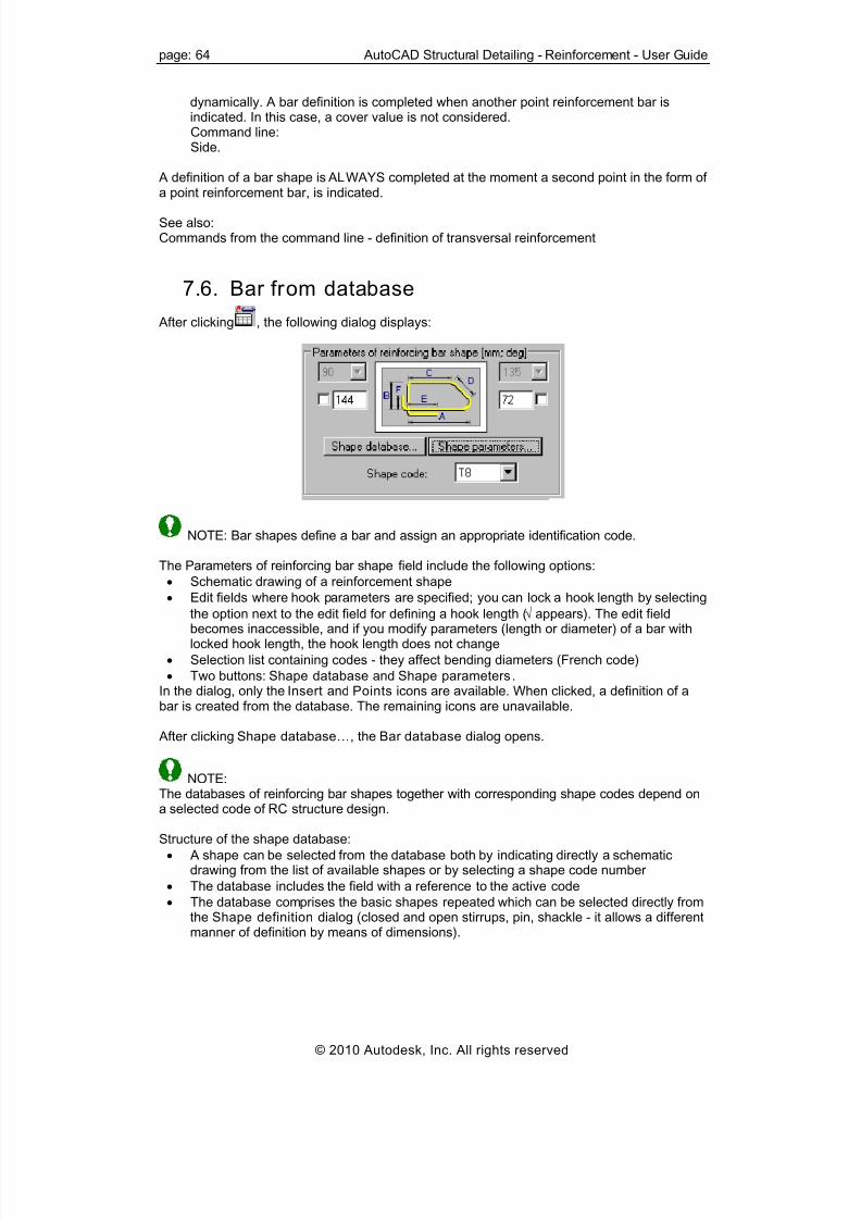
8/20/2019 Autocad Reinforcement Manual Eng
http://slidepdf.com/reader/full/autocad-reinforcement-manual-eng 71/222
page: 64 AutoCAD Structural Detailing - Reinforcement - User Guide
dynamically. A bar definition is completed when another point reinforcement bar isindicated. In this case, a cover value is not considered.Command line:Side.
A definition of a bar shape is ALWAYS completed at the moment a second point in the form of
a point reinforcement bar, is indicated.
See also:Commands from the command line - definition of transversal reinforcement
7.6. Bar from database
After clicking , the following dialog displays:
NOTE: Bar shapes define a bar and assign an appropriate identification code.
The Parameters of reinforcing bar shape field include the following options:
• Schematic drawing of a reinforcement shape• Edit fields where hook parameters are specified; you can lock a hook length by selecting
the option next to the edit field for defining a hook length (√ appears). The edit fieldbecomes inaccessible, and if you modify parameters (length or diameter) of a bar withlocked hook length, the hook length does not change
• Selection list containing codes - they affect bending diameters (French code)
• Two buttons: Shape database and Shape parameters.In the dialog, only the Insert and Points icons are available. When clicked, a definition of abar is created from the database. The remaining icons are unavailable.
After clicking Shape database…, the Bar database dialog opens.
NOTE:The databases of reinforcing bar shapes together with corresponding shape codes depend ona selected code of RC structure design.
Structure of the shape database:
• A shape can be selected from the database both by indicating directly a schematicdrawing from the list of available shapes or by selecting a shape code number
• The database includes the field with a reference to the active code
• The database comprises the basic shapes repeated which can be selected directly fromthe Shape definition dialog (closed and open stirrups, pin, shackle - it allows a differentmanner of definition by means of dimensions).
© 2010 Autodesk, Inc. All rights reserved

8/20/2019 Autocad Reinforcement Manual Eng
http://slidepdf.com/reader/full/autocad-reinforcement-manual-eng 72/222
AutoCAD Structural Detailing - Reinforcement - User Guide page: 65
To define bars from the database, select a bar from the available shape list, then define thenext bar segments by indicating next bar characteristic points presented in a schematicdrawing (you may also enter dimensions of individual segments from the keyboard).Once a bar is selected from the database, the bar segments are defined individually based onthe indicated points (there apply rigid rules of defining successive segments so that the barshape is maintained). While defining, the bar length is calculated automatically. The bardimensions proposed by default in the dialog are the dimensions of the recently-defined bar. A bar defined in the bar shape database remembers the shape of a selected bar type. Youcan replace the bar with a regular bar which does not remember the bar geometrical shape -to do that, use the EXPLODE option.There is also another method for defining bars. Once the Shape parameters… button isclicked, the additional dialog displays, and a table containing dimensions of individual barsegments is available. After determining bar dimensions, a completed bar may be added to aformwork.
© 2010 Autodesk, Inc. All rights reserved

8/20/2019 Autocad Reinforcement Manual Eng
http://slidepdf.com/reader/full/autocad-reinforcement-manual-eng 73/222
page: 66 AutoCAD Structural Detailing - Reinforcement - User Guide
The above dialog contains a table that displays dimensions of bar segments.The field with a shape code is filled out automatically depending on a typical shape selected.Both modes of reinforcement definition are synchronized with each other; both definitionmodes can be used alternately.
See also:Commands from the command line - definition of transversal reinforcement
7.7. Arbitrary bar shape
After clicking , the following dialog displays:
This dialog allows you to define any reinforcement shape. You can select a hook type at thebeginning and end of a defined reinforcement and define bar anchors on its both ends; adefault value of the anchor for an arbitrary bar equals zero. You can lock a hook length by
selecting the option next to the edit field for defining a hook length (√ appears). The edit fieldbecomes inaccessible. If you modify parameters (length or diameter) of a bar with locked hooklength, the hook length does not change.
Successive characteristic points include the bars of point reinforcement or characteristicpoints.Transversal reinforcement of arbitrary shape will be based on these points. You can specifiythe field with a shape code (a unique code of the bar shape). This code is presented in thereinforcement table; it will be also included in the information about the bar.
Four icons are active when defining this reinforcement type (the remaining icons areunavailable):
• Select - is used to define reinforcement on an open polyline (arcs may be includedthere)
• Pick point - is used to detect a contour (identically as for a polygon-shaped stirrup);a contour may include arc elements
• Points - is used to indicate directly any points. After selecting, the dialog closes, andthe cursor assumes the shape of a cross (see the ACAD command ‘line’). After definingthe first point determining a bar position, the bar length changes dynamically dependingon the cursor position. While indicating next bars, the defined bar is ‘wound’ aroundthese points, whereas the condition of a bending diameter is maintained automatically.
• Bars - is used to define a bar on the existing point reinforcement (pointreinforcement, i.e. presentation of longitudinal reinforcement within a cross section). Afterselecting, the dialog closes, and the cursor assumes the shape of a square (see the ACAD command ‘select’). A bar definition is completed when another point reinforcementbar is indicated.
See also:
Commands from the command line - definition of transversal reinforcement
© 2010 Autodesk, Inc. All rights reserved
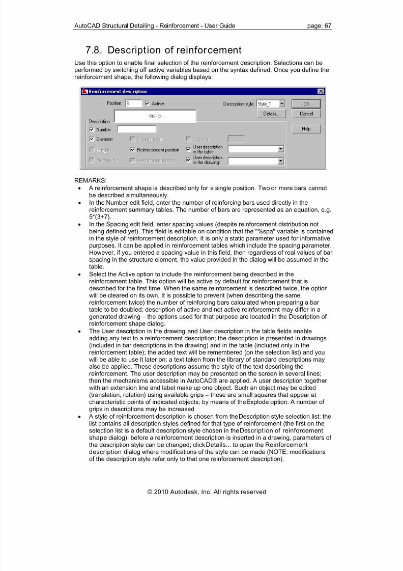
8/20/2019 Autocad Reinforcement Manual Eng
http://slidepdf.com/reader/full/autocad-reinforcement-manual-eng 74/222

8/20/2019 Autocad Reinforcement Manual Eng
http://slidepdf.com/reader/full/autocad-reinforcement-manual-eng 75/222
page: 68 AutoCAD Structural Detailing - Reinforcement - User Guide
NOTE:Whether any of the options listed above are selected, depends on the defined descriptionsyntax available in styles of reinforcement description. If for example, a bar symbol is to beincluded in the bar description, you should open the Description of reinforcement shapedialog, select reinforcement description (e.g. Bar shape), click Modify, switch on the
Reinforcement symbol option provided on the Description syntax tab, click the arrow button;the variable containing a bar symbol is added in the Description edit field; to end the operation,click Add.
7.9. Commands from the command line - definit ionof transversal reinforcement
The following parameters are specified in the command line while defining a transversal bar:Bar diameter or [Cover / Stirrup type / Define ] <6>: 8Select option [Diameter / Cover / Stirrup type / Define ] <Define>:
Reinforcement diameter <8>:Cover <5.5> : 6Stirrup type: [Polygon / Round / Pin / Shackle / Base / Any ] <Polygon>:
For a polygon-shaped sti rrup the following parameters may be defined:
Select option [DIagonal / Selection / INternal point] <Diagonal>:First cornerSecond corner or [Side / Back]Select objectHook location or [Side / Back]Internal pointHook location or [Side / Back]
For a round stirrup the following parameters may be defined:Select option [2points / Selection / Internal point ] <Selection>:Circle center;Circle diameter or [Diameter / Side / Back ]<33>:Hook locationSelect objectHook location or [Side / Back]Internal pointHook location or [Side / Back]
For a pin and shackle the following parameters may be defined:Select option [Points / BArs] <BArs>:Beginning point
End point or [Side / Back]:First pointSecond point or [Side / Back]:}where:beginning point - the first point determining the shape of a bar (bar beginning)end point - the last point determining the shape of a barside - determines on which side of a cross section contour of an RC element the currentsegment of reinforcement is to be locatedback - cancels the last command.
For bars from database the following parameters are defined:Bar code or [Select from database]Beginning point
Next point or [Side / Cover / 1hook / 2hook / Back]where:beginning point - the first point determining the shape of a bar (bar beginning)
© 2010 Autodesk, Inc. All rights reserved

8/20/2019 Autocad Reinforcement Manual Eng
http://slidepdf.com/reader/full/autocad-reinforcement-manual-eng 76/222
AutoCAD Structural Detailing - Reinforcement - User Guide page: 69
next point - next points determining the shape of a barside - determines on which side of a cross section contour of an RC element the currentsegment of reinforcement is to be locatedcover - value of a cover for the current segment of reinforcement1 hook - direction of the hook bending2 hook - direction of the hook bending (opposite to hook 1)
back - cancels the last command.
For a bar of arbitrary shape the following parameters may be defined:Beginning pointNext point or [Side / Cover / 1hook / 2hook / Back]where:beginning point - the first point determining the shape of a bar (bar beginning)next point - next points determining the shape of a barside - determines on which side of a cross section contour of an RC element the currentsegment of reinforcement is to be located (change of a bar position with respect to the line -points of definition to the opposite one)cover - value of a cover for the current segment of reinforcement1 hook – changes the direction of hook bending to the opposite
2 hook - direction of hook bendingback - cancels the last command.
7.10. Example of definition of transversalreinforcement
The following drawing illustrates the definition of transversal reinforcement in the cross sectionof the beam. For definition of the beam contours the Formworks - Beam macro has beenused.
To define transversal reinforcement of the RC beam, follow the steps below:DEFINITION OF THE BEAM FORMWORK
1. Run the Formworks – Beam macro by clicking icon.2. In the Formworks – Beam dialog specify the following parameters:- section type: 1 (rectangular)- beam type: 1 (single-span beam)- dimensions of the beam cross section: height = 600 mm, width = 300 mm- beam geometry as shown in the drawing below:
© 2010 Autodesk, Inc. All rights reserved

8/20/2019 Autocad Reinforcement Manual Eng
http://slidepdf.com/reader/full/autocad-reinforcement-manual-eng 77/222
page: 70 AutoCAD Structural Detailing - Reinforcement - User Guide
3. Click Insert in the Formworks – Beam dialog, and indicate the location of the beamformwork in the drawing.
DEFINITION OF THE BEAM REINFORCEMENT
1. Click the Reinforcement - section icon
2. In the Reinforcement – cross-section dialog, specify the following parameters:
• type of reinforcing bars: polygon-shaped (closed) stirrup
• bar diameter: 8 mm; cover of reinforcing bars: 30 mm
• steel grade: R
• shape parameters as shown in the drawing below
3. Click (Pick point), located on the right side of the dialog.4. In the drawing of the beam formwork, indicate a point within the beam cross section
and point 1 that determines the position of stirrup hooks.5. Accept the default reinforcement description proposed in the Reinforcement
description dialog by clicking OK. 6. Indicate the position of the reinforcement description by clicking Enter or right-clicking
the Enter option from the context menu.
The reinforcement in the beam cross section has been defined. To define the transversalreinforcement distribution along the beam length, follow these steps:
1. Click the Reinforcement distribution icon
2. Indicate the previously-defined stirrup and click ENTER; the Reinforcement detailingdialog displays. Select the following options:
• Distribution TYPE: linear (press the icon )
• Distribution METHOD: zone (press the icon )
• Viewing DIRECTION: click
• click OK. 3. Indicate the start distribution point (point 2 in the drawing presented at the beginning
of the example) and the end distribution point (point 3 in the drawing presented at thebeginning of the example).
4. Indicate the points of the zone beginning (point 4 in the drawing presented at the
beginning of the example) and the zone end (point 5 in the drawing presented at thebeginning of the example); click Enter. 5. Accept the default reinforcement distribution by clicking OK.
© 2010 Autodesk, Inc. All rights reserved

8/20/2019 Autocad Reinforcement Manual Eng
http://slidepdf.com/reader/full/autocad-reinforcement-manual-eng 78/222
AutoCAD Structural Detailing - Reinforcement - User Guide page: 71
6. Adopt the following parameters of description of the reinforcement distribution
• Type of reinforcing bar presentation: all
• Position: the Active option switched on
• Type of distribution description:
• Click OK.7. Indicate the location of the reinforcement description in the drawing by clicking Enter,
or right-clicking the Enter option from the context menu.
The defined transversal reinforcement with its distribution along the beam length is illustratedbelow.
© 2010 Autodesk, Inc. All rights reserved

8/20/2019 Autocad Reinforcement Manual Eng
http://slidepdf.com/reader/full/autocad-reinforcement-manual-eng 79/222
page: 72 AutoCAD Structural Detailing - Reinforcement - User Guide
8. DEFINITION OF REINFORCEMENT - SPECIALSTIRRUPS
8.1. DEFINITION OF BAR REINFORCEMENT - barsection (special stirrups)
Use this option to define stirrups (transversal reinforcement) in the cross-section of an RCstructure element. There are three ways to access this option from:
• Menu: Reinforcement / Special stirrups
• Ribbon: ASD - Reinforcement / Reinforcement - definition / Special stirrups
• Toolbar: Definition-bars / Special stirrups
• Command line: RBCR_DEF_STIRRUP_SPEC.
Once activated, the following dialog displays:
The Special sti rrups dialog is split into three parts:
• The left side of the dialog contains basic information concerning the reinforcement:diameter, cover and reinforcing steel grade adopted from preference settings
• The middle of the dialog includes icons that represent basic shapes of the transversalreinforcement and allow selection of the stirrup type; once the transversal reinforcementtype is selected, contents of the field with parameters of the reinforcement shape changes
• The right side of the dialog includes several icons which are used to select a mode ofgraphical reinforcement definition; if they are clicked, the graphic interface mode isselected according to a specific way of contour definition. NOTE: Bars can only bedisplayed after one of these icons is selected.
The dialog opens and displays the transversal reinforcement type defined and the parameters
adopted.
The following types of special stirrups are available:
• four-leg stirrups
• stirrups made of bars in the shape of the double U-letter.
Once you define the reinforcement shape, the Reinforcement description dialog displays.
NOTE: After defining the four-leg stirrups, the description command is run automatically. Thecommand works for a selection and describes bars one by one moving from the first one to thesecond without the necessity to reactivate the command. It is possible to interrupt bar
description and describe only one bar.
© 2010 Autodesk, Inc. All rights reserved

8/20/2019 Autocad Reinforcement Manual Eng
http://slidepdf.com/reader/full/autocad-reinforcement-manual-eng 80/222
AutoCAD Structural Detailing - Reinforcement - User Guide page: 73
8.2. Special stirrups - four-leg stirrups
After clicking , the following dialog displays:
To define a bar, define the following parameters:
• A bar diameter (the diameter defined in the dialog is adopted by default)
• A cover of reinforcing bars (the cover defined in the dialog is adopted by default)
• In the Parameters of reinforcing bar shape field - anchor parameters for bar ends, i.e.hook angle, length and value of the a parameter which defines a clear distancebetween middle stirrup legs.
The shape of a bar presented in a schematic drawing is adjusted dynamically to the specifiedvalues of a hook bending angle. Standard hook angle values include:
⇒ 0° ⇒ 90° ⇒ 135° ⇒ 180° ⇒ -90° ⇒ -135°
⇒ -180°.
The following icons display on the right side of the dialog while a rectangular stirrup is defined(the remaining icons are unavailable):
• Diagonal - is used to create a rectangular contour by defining a diagonal. Afterselecting, the dialog closes, and while the cursor is moved, a defined rectangularstirrup is presented dynamically
• Select - is used to indicate directly a rectangular contour. After selecting, thedialog closes, and the cursor assumes the shape of a square (see the ACADcommand ‘copy’ - the phase of selecting the object to be copied). After selecting anypoint on the screen, the ACAD object is detected and a transversal reinforcement(stirrup) is drawn within the indicated object
• Pick point - function that allows searching a closed contour (rectangle) by clickinginside the contour. After selecting, the dialog closes, and the cursor assumes theshape of a cross (see the ACAD command ‘hatch’). The detected rectangle ischanged to a stirrup shaped like a detected contour, but decreased by the covervalue.
© 2010 Autodesk, Inc. All rights reserved

8/20/2019 Autocad Reinforcement Manual Eng
http://slidepdf.com/reader/full/autocad-reinforcement-manual-eng 81/222
page: 74 AutoCAD Structural Detailing - Reinforcement - User Guide
8.3. Special stirrups - bars in the shape of thedouble U-letter
After clicking , the following dialog displays:
To define a bar, the following should be specified:• Bar diameter (the diameter defined in the dialog is adopted by default)
• Cover of reinforcing bars (the cover defined in the dialog is adopted by default)
• In the Parameters of reinforcing bar shape field - anchor parameters for bar ends, i.e.hook angle, length and value of the a parameter which defines a length of overlappingbars.
The shape of a bar presented in the schematic drawing is adjusted dynamically to thespecified values of a hook bending angle. Standard hook angle values include:
⇒ 0° ⇒ 90° ⇒ 135° ⇒ 180°
⇒ -90° ⇒ -135° ⇒ -180°.
The following icons are available in the right part of the dialog box while a rectangular stirrup isdefined (the remaining icons are unavailable):
• Diagonal - is used to create a rectangular contour by defining a diagonal. Afterselecting, the dialog box closes, and while moving the cursor, a defined rectangularstirrup is presented dynamically
• Select - is used to indicate directly a rectangular contour. After selecting, thedialog box closes, and the cursor assumes the shape of a square (see the ACADcommand ‘copy’ - the phase of selecting the object to be copied). After selecting any
point on the screen, the ACAD object is detected and a transversal reinforcement(stirrup) is drawn within the indicated object
• Pick point – is used to search a closed contour (rectangle) by clicking inside thecontour. After selecting, the dialog closes, and the cursor assumes the shape of across (see the ACAD command ‘hatch’). The detected rectangle is changed to astirrup shaped like a detected contour, but decreased by the cover value.
© 2010 Autodesk, Inc. All rights reserved

8/20/2019 Autocad Reinforcement Manual Eng
http://slidepdf.com/reader/full/autocad-reinforcement-manual-eng 82/222
AutoCAD Structural Detailing - Reinforcement - User Guide page: 75
9. DEFINITION OF REINFORCEMENT - POINTREINFORCEMENT
9.1. Point reinforcementUse this option to define distribution of reinforcing bars in an element of an RC structure.There are two ways to access this option from:
• Menu: Reinforcement / Reinforcement - point
• Ribbon: ASD - Reinforcement / Reinforcement - definition / Reinforcement - point
• Toolbar: Definition - bars / Reinforcement - point
• Command line: RBCR_DISTRIBUTION_POINT.
The dialog displays if reinforcement has been selected or if a number of a reinforcementpositions have been specified in the command line (by default, the number of the recently-defined bar is suggested):
• If Main Reinforcement has been selected, the following data displays:- diameter,- position number,- appropriate bar length.
• If Distributed Reinforcement has been selected, the following data displays:- diameter,- position number (both parameters are not accessible),- edit field (used for definition of the reinforcement length).
NOTE:When defining the point reinforcement (which does not refer to the existing reinforcement, e.g.when defining distributed reinforcement), the dialog opens after clicking ESC.
The dialog is opened automatically from the level of the dialog for reinforcement distribution.Then the dialog opens in the mode of main reinforcement definition with an appropriatediameter, position number, and appropriate bar length (the parameters are not accessible).
After selecting the option, the following dialog displays:
The above dialog is divided into three principal parts:
• The left side of the dialog (the Reinforcement type field) contains basic informationconcerning the reinforcement:- Reinforcement type: main, distributed- Edit field where reinforcement length can be defined- Reinforcement diameter
There is also information concerning hooks on ends of a reinforcing bar (beginning andend of a bar).
© 2010 Autodesk, Inc. All rights reserved

8/20/2019 Autocad Reinforcement Manual Eng
http://slidepdf.com/reader/full/autocad-reinforcement-manual-eng 83/222
page: 76 AutoCAD Structural Detailing - Reinforcement - User Guide
The middle of the dialog includes three icons, which when clicked, change the content of
the Distribution parameters fie - regular distribution of reinforcement
- automatic distribution of reinforcement
- any distribution of reinforcement
Note: The Automatic and Any distribution of reinforcement parameters are coupled.Regular distribution of reinforcement cannot be combined with Automatic or Anydistribution of reinforcement.
• The right side ld with parameters of reinforcement distribution:
• of the dialog provides a group of icons which are used for selecting the graphic definitionmode; clicking these icons activate different modes of graphic interface.
The dialog remains visible throughout the process of defining reinforcement distribution, whichenables you to change the distribution parameters of reinforcement while defining it. Allmethods of bar distribution are applied with respect to one reinforcement position.The distribution of a given reinforcement position is completed by clicking OK. Afterwards, thedistribution description is defined.
See also:Example of definition of point reinforcement
9.2. Regular distribution of reinforcement
Access this option by clicking , the Reinforcement - point dialog displays:
The left side of the dialog contains the parameters controlling reinforcement distribution withinone zone:
• S - reinforcement spacing
• n - number of spacings between bars in a given zone
• c - distance (cover) between bars and reinforcement or polylines along whichreinforcement is distributed (the default value equals zero).
The cover is always interpreted as perpendicular to a bar or formwork line.• As - area of reinforcement per length unit.
A drawing of reinforcement distribution is provided, whereas directly underneath, the optionsthat allow positioning displays.
The following methods of reinforcement distribution are available:
1. - along the whole indicated bar
2. - along the whole indicated segment of a bar
3. - along the fragment of the indicated bar segment
4. - along the indicated polyline (arc, circle, line i.e. between 2 points).
When defining the distribution applying the methods 1 or 2, you should indicate a bar orsegment of reinforcement; the cursor assumes the shape of a square. After selection, and
© 2010 Autodesk, Inc. All rights reserved

8/20/2019 Autocad Reinforcement Manual Eng
http://slidepdf.com/reader/full/autocad-reinforcement-manual-eng 84/222
AutoCAD Structural Detailing - Reinforcement - User Guide page: 77
initial positioning of reinforcement (according to the distribution parameters defined in thedialog), you specify (by means of the options available in the command line) the followimgparameters:
• Change of the side on which the distributed reinforcement is positioned - with respect tothe bar (the Side command)
• Change of the parameter spacing / number (the Spacing / Number command)
• Justify - positioning the distribution centrally or justified to the left or right side of thedistribution
• Adjust - uniform distribution of reinforcement along the whole distribution length
• Cover - change of a cover value = offset.
If distribution is defined by means of method 3, the extreme points are specified. In the case ofdistribution defined with the use of method 4, reinforcement is distributed on the wholeselected objects such as line, polyline, circle.You may change values of the parameters using the options available in the dialog, however,the side on which reinforcement is positioned cannot be changed.
The method of reinforcement distribution consists in specifying the number of reinforcing
bars/spacing or reinforcement area per one running meter. Hooks are not considered in caseof distribution along the bar. For distribution along the segment, the length between fillets istaken into account.
Command line (regular distribution)
Distribution type: [Regular / Automatic / Any] Regular
RegularSelect Bar or [Segment / Segment fragment / Polyline]
Bars Select bar or [Side / Back ]
SegmentSelect bar segment or [Side / Back ]
Segment fragmentSelect bar segmentSelect beginning point or [Back]Select end point or [Side / Back]
PolylineSelect object or [Side / Back]
9.3. Automatic distribution of reinforcement
After clicking , the Reinforcement - point dialog displays:
© 2010 Autodesk, Inc. All rights reserved

8/20/2019 Autocad Reinforcement Manual Eng
http://slidepdf.com/reader/full/autocad-reinforcement-manual-eng 85/222
page: 78 AutoCAD Structural Detailing - Reinforcement - User Guide
NOTE: The options: bar intersection, tangent to bar, and on bar are not currently available.
The method is intended only for defining bar distribution for the existing reinforcement. It hasbeen designed so that in typical cases, you can easily arrange bars based on the followingcharacteristic points of reinforcement (not all the options are available):
• hook bending
• end of bar or segment
• center of bar or segment
• intersection of bars - this option is not currently available
• tangentially to bar - this option is not currently available
• on bar - this option is not currently available.
Bars may be distributed along the following:
• A selected bar segment -
• A defined bar shape (whole bar) - .
Commands (of the command line) are set so you can select one or several bars/segmentssimultaneously. You can also change position of the reinforcement being distributed withrespect to a bar / segment axis.
9.4. Any reinforcement distribution
After clicking , the Reinforcement - point dialog displays:
The distribution method is intended for all cases where standard methods of reinforcementdistribution prove ineffective. This method allows you to position a bar or a bar group freely,based on the distribution carried out earlier; the distribution may also be definedindependently.
The method described enables distribution of one or more bars simultaneously. For at leasttwo bars that are inserted concurrently, you can determine the distance between bars and
their orientation (horizontally or vertically ) while inserting.Precise arrangement of bars are facilitated by the use of characteristic points (characteristicpoints of AutoCAD®).
For bars defined as vertical, and when applying points characteristic for reinforcement, barorientation will always be perpendicular to the bar / segment axis.
The right side of the dialog contains the following distribution methods:
Insert This options allows you to define the distribution; the definition consists of successivepositions of reinforcement. The only assistance available while defining distribution is offered
the characteristic points - snap points within AutoCAD®.Distribution may also be defined from the level of the command line.
© 2010 Autodesk, Inc. All rights reserved

8/20/2019 Autocad Reinforcement Manual Eng
http://slidepdf.com/reader/full/autocad-reinforcement-manual-eng 86/222
AutoCAD Structural Detailing - Reinforcement - User Guide page: 79
Insert between The option allows you to indicate two point bars and insert 1 bar or a group of bars betweenthem. When inserting a bar, the order between the indicated bars changes; if the two selectedbars had been inserted using the characteristic points, then the bars inserted should behaveidentically as base bars; if not, the bars added are inserted along a straight line between the
existing bars.
Delete The option permits deleting an indicated bar.
Command line (any distribution)
Distribution type: [Regular / Automatic / Any]: Any
Select attachment point or [Modify properties / Insert between / Delete / Snap / Back]
Modify parameters [Number of bars / Spacing / Orientation]
Number of bars <2> : 1Spacing <0.12> : 0.18Orientation <V> : H
Insert BetweenSelect initial barSelect end bar or [Back ]
DeleteSelect bar or [Back]
9.5. Reinforcement descriptionThis option is used to define the final selection of reinforcement description and distribution.
The way to access this option is to click Modify reinforcement description option . The following dialog displays:
NOTE: Two additional options are available in the dialog as shown below: Descriptionstyle (used to modify a description style of the reinforcement chosen) and the Details button,which when clicked, opens the dialog used for modifying a style of reinforcement description(shape).
The options provided in this dialog, enable final selection of reinforcement description anddistribution by switching off active variables initialized based on the syntax defined.
© 2010 Autodesk, Inc. All rights reserved

8/20/2019 Autocad Reinforcement Manual Eng
http://slidepdf.com/reader/full/autocad-reinforcement-manual-eng 87/222
page: 80 AutoCAD Structural Detailing - Reinforcement - User Guide
The dialog contains the following options:
• The Active option is used to assign a description to a reinforcement which already has adescription. This is used when the same reinforcement is included in multiple calculationswhen preparing a reinforcement table
• The following icons are used to define the manner of presenting the distribution:
- all elements are presented in a drawing showing given reinforcement distribution
- only the middle representative of the distribution in a given zone is presented (theremaining elements are not visible)
- only the extreme elements of the distribution in a given zone are presented (theremaining elements are not visible)
- indicate graphically distribution elements to be presented
• The fields: User description in the drawing and User description in the table allows you toadd any text to a reinforcement description. The description will be presented in drawings(included in bar descriptions in the drawing) and in the table (included only in thereinforcement table). The added text is saved (on the selection list) and you will be ableto use it later on; a form of the displayed description is closely connected with theappropriate and default style of reinforcement description. The user description displays
on several lines; then the mechanisms accessible in AutoCAD® are applied. A userdescription together with an extension line and label make up one object. Such an objectmay be edited (translation, rotation) using available grips – these are small squares thatappear at characteristic points of indicated objects; by means of the AutoCAD®Structural Detailing Explode option, it is possible to increase a number of grips indescriptions
• A style of reinforcement description is chosen from the Style selection list; the listcontains all description styles defined for that type of reinforcement (the first on theselection list is a default description style chosen in the Description of reinforcementshape dialog); before a reinforcement description is inserted in a drawing, parameters ofthe description style can be changed. Clicking Details, opens the Reinforcementdescription dialog where modifications of the style can be made (NOTE: modifications ofthe description style refer only to that one reinforcement description).
NOTE:To include a bar symbol in the bar description:
1. Open the Descript ion of reinforcement shape dialog.2. Select reinforcement description (e.g. Bar shape).3. Click Modify.4. Select the Reinforcement symbol option provided on the Description syntax tab.5. Click the button with the arrow; the variable containing a bar symbol will be added in the
Description edit field;6. To end the operation, click Add.
NOTE: You may clear the active description components. The additional description allows
entering an additional text. The comments entered are remembered and may be reused lateron.
9.6. Example of definition of point reinforcement
The following example illustrates the definition of point reinforcement in the cross section ofthe beam. For definition of the beam contours the Formworks - Beam macro has been used.
© 2010 Autodesk, Inc. All rights reserved

8/20/2019 Autocad Reinforcement Manual Eng
http://slidepdf.com/reader/full/autocad-reinforcement-manual-eng 88/222
AutoCAD Structural Detailing - Reinforcement - User Guide page: 81
To define point reinforcement in the beam:1. Define transversal and longitudinal reinforcement
DEFINITION OF THE BEAM FORMWORK
1. Run the Formworks – Beam macro by clicking .
2. In the Formworks – Beam dialog, specify the following parameters:• section type: 1 (rectangular)
• beam type: 1 (single-span beam)
• dimensions of the beam cross section: height = 600 mm, width = 300 mm
• beam geometry displays as follows:
3. Click Insert in the Formworks – Beam dialog.4. Indicate the location of the beam formwork in the drawing
DEFINITION OF THE BEAM REINFORCEMENT
1. Click the Reinforcement – cross-section icon2. In the Reinforcement – cross-section dialog, specify the following parameters:
• type of reinforcing bars: polygon-shaped (closed) stirrup• bar diameter: 8 mm; cover of reinforcing bars: 30 mm
• steel grade: R
• shape parameters as shown in the drawing below
3. Click (Pick point).
4. In the drawing of the beam formwork indicate a point within the beam cross sectionand point 1 that determines the position of stirrup hooks.
5. Accept the deafult reinforcement description proposed in the Reinforcementdescription dialog by clicking OK.
6. Indicate the position of the reinforcement description in the drawing by clicking Enter ,or right-clicking the Enter option from the context menu.
Define the straight longitudinal reinforcement (with the reinforcement in the beam crosssection already defined), as follows:
1. Click the Reinforcement - elevation icon2. In the Reinforcement – elevation dialog, specify the following parameters:
• type of reinforcing bars: straight bar• bar diameter: 12 mm; cover of reinforcing bars: 30 mm
© 2010 Autodesk, Inc. All rights reserved

8/20/2019 Autocad Reinforcement Manual Eng
http://slidepdf.com/reader/full/autocad-reinforcement-manual-eng 89/222
page: 82 AutoCAD Structural Detailing - Reinforcement - User Guide
• steel grade: R
• shape parameters as shown below
3. Click (2 points).4. In the drawing of the beam formwork, indicate point 2 and point 3.5. Accept the deafult reinforcement description proposed in the Reinforcement
description dialog by clicking OK.6. Indicate the position of the reinforcement description in the drawing by clicking Enter
or right-click the Enter option from the context menu.
Once the transversal and longitudinal reinforcement is defined, define the point reinforcementas follows:
1. Click the Reinforcement - point icon2. Indicate the defined longitudinal bar.
3. Specify the following parameters; bar distribution: regular
4. Click (Whole segment), indicate the upper part of the defined stirrup, and clickEnter.
5. Specify the following parameters:
• number of bars n = 3
• leave default values of the remaining parameters6. Click OK.7. Adopt the following parameters of the description of reinforcement distribution:
• type of reinforcing bar representation: all• position: the Active option switched on
• type of distribution description:8. Click OK.9. Indicate the position of the reinforcement description in the drawing by clicking Enter
or right-clicking the Enter option from the context menu.
The defined point reinforcement is presented in red in the drawing below.
© 2010 Autodesk, Inc. All rights reserved

8/20/2019 Autocad Reinforcement Manual Eng
http://slidepdf.com/reader/full/autocad-reinforcement-manual-eng 90/222
AutoCAD Structural Detailing - Reinforcement - User Guide page: 83
10. DEFINITION OF REINFORCEMENT - SPECIALBARS
10.1. Special reinforcementUse this option to define reinforcing bars used in different elements of RC structures (e.g.crest-shaped reinforcement, corbel reinforcement, transport handles). There are three ways toaccess this option from:
• Menu: Reinforcement / Special reinforcement
• Ribbon: ASD - Reinforcement / Reinforcement - definition / Special reinforcement
• Toolbar: Definition - bars / Special reinforcement
• Command line: RBCR_DEF_BARLIBSPECIAL.
Once activated, the following dialog displays:
The dialog is divided into three parts:
• The left side of the dialog contains basic information concerning reinforcement: diameter,cover and steel grade adopted from the preference settings
• The middle of the dialog includes parameters of a selected type of special reinforcement;left-clicking the field containing the drawing of the special reinforcement opens anadditional dialog where reinforcement type (shape) are chosen; selection of specialreinforcement type changes the contents of the field with parameters of reinforcementshape
• The right side of the dialog comprises a few icons used for selecting a mode of graphicalreinforcement definition (the number of icons depends on a chosen type of specialreinforcement); clicking an icon indicates selection of the graphical interface modeaccording to the specific character of region definition. NOTE: Bars can only be displayed
after one of these icons is selected.
The following types of special reinforcement are available:
• 3D reinforcement (defined in the drawing plane): corbel reinforcement, goalpostsreinforcement and helix of RC structure elements with round cross-section
• transport handles
• Remaining reinforcement types: crest-shaped reinforcement, arc-shaped reinforcement,vertical loop.
Once definition of reinforcement shape is complete, the Reinforcement description dialogdisplays and allows you to select elements of reinforcement description. Reinforcing bars canalso be defined by means of the commands available.
© 2010 Autodesk, Inc. All rights reserved

8/20/2019 Autocad Reinforcement Manual Eng
http://slidepdf.com/reader/full/autocad-reinforcement-manual-eng 91/222
page: 84 AutoCAD Structural Detailing - Reinforcement - User Guide
10.2. Crest-shaped reinforcement
After selecting crest-shaped reinforcement, the Special reinforcement dialog displays:
NOTE:Crest-shaped reinforcement can be defined only within a rectangular region.
To define a bar, specify the following:
• Bar diameter (the diameter defined in the dialog is adopted by default)
• Reinforcing bar cover (the cover defined in the dialog is adopted by default)
• In the Shape parameters field – anchorage parameters of reinforcing bar ends, i.e. hookangle and length as well as number of legs in crest-shaped reinforcement; you can lock a
hook length by selecting the option next to the edit field for defining a hook length (√ appears). The edit field becomes inaccessible. If you modify parameters (length or
diameter) of a bar with locked hook length, the hook length does not change.
While defining the crest-shaped reinforcement, the following icons are available in the dialog:
• Diagonal - is used to create a rectangular region by defining a diagonal. Afterselecting, the dialog closes, and when the cursor is moved, the defined reinforcement ispresented dynamically.
Command line:First cornerSecond corner or [Orientation / First hook / Second hook / Cover]
where:
First corner – indicates the initial apex of a rectangle within which crest-shapedreinforcement is to be definedSecond corner - indicates the second apex of a rectangle (along the rectangle diagonal)within which crest-shaped reinforcement is to be definedOrientation – rotates (changes position) of reinforcement within the contourFirst hook – changes the hook bend at the beginning of a reinforcing bar (first corner) tothe oppositeSecond hook - changes hook bend at the end of a reinforcing bar to the oppositeCover – defines a cover value globally for the entire region of a rectangle
• Pick point – is used to search a closed region in the shape of a rectangle by clickinginside the region. After selecting any point, the dialog closes, and the cursor assumes theform of a cross (see the ACAD command ‘copy’ - the stage of indicating the beginning
and end points), and the minimal contour is detected.
© 2010 Autodesk, Inc. All rights reserved

8/20/2019 Autocad Reinforcement Manual Eng
http://slidepdf.com/reader/full/autocad-reinforcement-manual-eng 92/222
AutoCAD Structural Detailing - Reinforcement - User Guide page: 85
• Select – is used to indicate a rectangle-shaped contour. After selecting this option,the dialog closes, and the cursor assumes the form of a square (see the ACADcommand ‘copy’ - the stage of selecting an object for copying). After selecting any pointon the screen, an ACAD object is detected and reinforcement is drawn within theindicated object.
Command line (for the options: Pick point and Select)Select internal point of the object (for the Pick point option)Select object (for the Select option)Orientation / First hook / Second hook / Cover
where:orientation - rotation of reinforcement within the contour by indicating a contour side
first hook - change of the hook bend at the beginning of a reinforcing bar (first corner) tothe oppositesecond hook - change of hook bend at the end of a reinforcing bar to the opposite
cover - definition of a cover value globally for the entire region of a rectangle
See also:Example definition of crest-shaped reinforcement
10.3. Example definition of crest-shapedreinforcement
Use this option to define the crest-shaped reinforcement within the rectangle as shown below:
To define the crest-shaped reinforcement follow these steps:
1. In the Special Reinforcement dialog choose the reinforcement type – crest-shapedreinforcement.
2. Define the following values in the dialog (the Shape parameters field):
• hook bend angles at the bar beginning and end 90 degrees,
• hook lengths 0.06 m,
• number of legs n = 7
3. Click (Diagonal). 4. Indicate a first rectangle apex (see the above drawing).5. In the command line, choose the Second hook command (by entering the capital letter) –
it changes a hook position on the bar end.6. In the command line, choose the Orientation command – it rotates reinforcement within
the contour7. Indicate a second rectangle apex (see the above drawing) – the reinforcement obtained is
shown below.
© 2010 Autodesk, Inc. All rights reserved

8/20/2019 Autocad Reinforcement Manual Eng
http://slidepdf.com/reader/full/autocad-reinforcement-manual-eng 93/222
page: 86 AutoCAD Structural Detailing - Reinforcement - User Guide
10.4. Arc-shaped reinforcement
After selecting the arc-shaped reinforcement, the Special reinforcement dialog displays:
To define a bar, specify the following:
• Bar diameter (the diameter defined in the dialog is adopted by default)• Reinforcing bar cover (the cover defined in the dialog is adopted by default)
• In the Shape parameters field – anchorage parameters for reinforcing bar ends, i.e. hookangle and length; you can lock a hook length by selecting the option next to the edit field
for defining a hook length (√ appears). The edit field becomes inaccessible. If you modifyparameters (length or diameter) of a bar with locked hook length, the hook length doesnot change.
While defining the arc-shaped reinforcement, the following icons are available:
• Start - Center - End – is used to define an arc by specifying three snap points of thearc: arc beginning point, arc center and arc end point. After selecting any point, thedialog closes, and as the cursor is moved, the reinforcement is presented dynamically
Command line:Select start pointSelect arc centerSelect arc end
or
Select arc centerSelect arc startSelect arc end or [Angle / Arc length]
where:
start point – arc beginningarc end - end pointarc center – point being arc centerangle – value of arc anglelength – value of arc length
© 2010 Autodesk, Inc. All rights reserved

8/20/2019 Autocad Reinforcement Manual Eng
http://slidepdf.com/reader/full/autocad-reinforcement-manual-eng 94/222
AutoCAD Structural Detailing - Reinforcement - User Guide page: 87
• 3 Points – the function which enables arc definition by specifying three pointsbelonging to the arc. The dialog box closes; while moving with the cursor thereinforcement being defined is presented dynamically
Command line:Select first point
Select second pointSelect third point
where:first, second and third points denote successive points belonging to an arc
• Select – is used to indicate directly an arc-shaped object. After selecting, the dialogcloses, and the cursor assumes the shape of a square (see the ACAD command ‘copy’ –the stage of selecting an object for copying). Once any element is selected, an ACADobject is detected on the screen and reinforcement is drawn within the indicated object.
Command line:Select objectSide1 Hook2 Hook
where:object – arc or polyline segmentside – modifies reinforcement position with respect to an object (formwork)1 hook – direction of hook bend2 hook - direction of hook bend (opposite in relation to hook 1)
10.5. 'Goalposts' reinforcement
After selecting the ‘goalposts’ reinforcement, the Special reinforcement dialog displays:
© 2010 Autodesk, Inc. All rights reserved

8/20/2019 Autocad Reinforcement Manual Eng
http://slidepdf.com/reader/full/autocad-reinforcement-manual-eng 95/222
page: 88 AutoCAD Structural Detailing - Reinforcement - User Guide
To define a bar, specify the following:
• Bar diameter (the diameter defined in the dialog is adopted by default)
• Reinforcing bar cover (the cover defined in the dialog is adopted by default)
• In the Shape parameters field – reinforcement leg length (dimension perpendicular to thedrawing plane).
While defining the ’goalposts’ reinforcement, the following icons are available in the dialog:
• Diagonal – is used to define a rectangular region by defining a diagonal. Afterselecting, the dialog closes, and while moving the cursor, the reinforcement beingdefined is presented dynamically.
Command line:First cornerSecond corner or [Orientation / Cover]
where:first corner - indicates the initial apex of a rectangle within which reinforcement is to bedefined
second corner - indicates the second apex of a rectangle (along the rectangle diagonal)within which reinforcement is to be definedorientation - rotates (changes position) of reinforcement within the contour; indicateslocation of the bar open segmentside - modification of reinforcement position with respect to an object (formwork)
• Points – is used to define the reinforcement by specifying positions of reinforcementsnap points
Command line:Select first pointSelect second point or [Cover]Select third point or [Cover]
where:first, second and third points – successive snap points of reinforcement (see the drawingbelow)cover – determines cover value for individual segments of reinforcement
• Select – is used to indicate the object of reinforcement shape. After selecting, thedialog closes, and the cursor assumes the shape of a square (see the ACAD command‘copy’ – the stage of selecting an object for copying). Once any point is selected, the ACAD object is detected on the screen and a stirrup is drawn within an indicated object
Command line:Select objectOrientation
where:object – rectangle-shaped contourorientation – rotates (changes position) of reinforcement inside the contour; indicateslocation of bar open segment
© 2010 Autodesk, Inc. All rights reserved

8/20/2019 Autocad Reinforcement Manual Eng
http://slidepdf.com/reader/full/autocad-reinforcement-manual-eng 96/222
AutoCAD Structural Detailing - Reinforcement - User Guide page: 89
10.6. Corbel reinforcement
After selecting the corbel reinforcement (e.g. short cantilevers to be placed under a cranegirder), the Special reinforcement dialog displays:
To define a bar, specify the following:
• Bar diameter (the diameter defined in the dialog is adopted by default)
• Reinforcing bar cover (the cover defined in the dialog is adopted by default)
• In the Shape parameters field – reinforcement leg length (‘depth’) (dimensionperpendicular to the drawing plane).
While defining the corbel reinforcement, click (Points), to define successive snap points forthis type of reinforcement.
Command line:Select first pointSelect second point or [Side / Cover]Select third point or [Side / Cover]Indicate location of open segment of a bar
where: first, second and third points – successive reinforcement snap points (see the drawingbelow)
Cover – determines a cover value for individual segments of reinforcementSide – changes position of reinforcement with respect to an object (formwork)Location of open segment of a bar – indicates a point (in the plane) at which bar opening islocated – see the drawing below.
© 2010 Autodesk, Inc. All rights reserved

8/20/2019 Autocad Reinforcement Manual Eng
http://slidepdf.com/reader/full/autocad-reinforcement-manual-eng 97/222
page: 90 AutoCAD Structural Detailing - Reinforcement - User Guide
See also:Example definition of corbel reinforcement
10.7. Example definit ion of corbel reinforcement
The following figure displays the reinforcement of a cantilever (to be provided under a cranegirder): shown in the figure below, the user should follow the steps below, for example:
To define the reinforcement of a cantilever, specify the following:
• In the Special reinforcement dialog, select the reinforcement type – corbel reinforcement
• Define the value (in the Shape parameters field) of leg length equal to 30 cm
• Click (Points)
• Indicate point 1
• In the command line select the Side command – it modifies position of reinforcement withrespect to the object (formwork)
• Indicate successive points: 2 and 3 (see the figure above)
• Indicate point 1 as a point of reinforcement opening; the defined reinforcement displays inthe figure below.
© 2010 Autodesk, Inc. All rights reserved

8/20/2019 Autocad Reinforcement Manual Eng
http://slidepdf.com/reader/full/autocad-reinforcement-manual-eng 98/222
AutoCAD Structural Detailing - Reinforcement - User Guide page: 91
10.8. Helix
After selecting reinforcement in the form of helix, the Special reinforcement dialog displays:
NOTE:The helix is defined for two types of cross-section of an RC structure element (contour): circleor regular polygon.
To define a bar, the following should be specified:
• Bar diameter (the diameter defined in the dialog is adopted by default)• Reinforcing bar cover (the cover defined in the dialog is adopted by default)
• In the Shape parameters field – anchorage parameters for reinforcing bar ends, i.e. hookangle and length; you can lock a hook length by selecting the option next to the edit field
for defining a hook length (√ appears). The edit field becomes inaccessible. If you modifyparameters (length or diameter) of a bar with locked hook length, the hook length doesnot change.
The helix is a three-dimensional reinforcement. This reinforcement type is defined in thedrawing plane. The helix is defined in two stages:
• Definition of reinforcement within the cross-section of an RC structure element (e.g.column)
• Definition of reinforcement along the length of RC structure element.
© 2010 Autodesk, Inc. All rights reserved

8/20/2019 Autocad Reinforcement Manual Eng
http://slidepdf.com/reader/full/autocad-reinforcement-manual-eng 99/222
page: 92 AutoCAD Structural Detailing - Reinforcement - User Guide
NOTE:It is possible to modify a helix pitch during definition of this reinforcement type.
Total length of this reinforcement type is calculated according to the following formula:
L = C / B * π * (A + d) + hook lengths
where (see the drawing below):L – total helix lengthC – helix length in planeB – helix pitch A – helix internal diameterd – bar diameter.
While defining the helix, the following icons are available in the right part of the dialog:
• Points – used to define a closed region by specifying circle center and circle radius(or diameter) as well as indicating a region of reinforcement distribution - beginning andend of the region within which reinforcement is distributed (e.g. along the column length)
Command line:Definition of reinforcement within a cross-sectionCircle center {2Points / 3Points]Circle radius [Diameter]
Definition of reinforcement along the length of reinforced elementSelect first pointSelect second point [Spiral pitch]
where:a circle is defined within the cross-section by specifying: circle center and circleradius/diameter or by determining 2 or 3 points belonging to a circlefirst point – beginning point of the helix along the length of an RC elementsecond point – end point of the helix along the length of an RC elementspiral pitch – value of the helix pitch
• Pick point – is used to search a closed region by clicking inside the region. Afterselecting, the dialog closes, and the cursor assumes the form of a cross (see the ACADcommand ‘copy’ - the stage of indicating the beginning and end points). Once any pointis selected, the minimal contour is detected; the helix is defined by indicating thefollowing geometric figures: regular polygon and circle; to conclude the operation, youhave to indicate the region of reinforcement distribution – beginning and end of theregion within which reinforcement is distributed (e.g. along the column length)
Command line Definition of reinforcement within a cross-sectionSelect internal point of the objectOrientation
Definition of reinforcement along the length of reinforced elementSelect first pointSelect second point [Spiral pitch]
© 2010 Autodesk, Inc. All rights reserved

8/20/2019 Autocad Reinforcement Manual Eng
http://slidepdf.com/reader/full/autocad-reinforcement-manual-eng 100/222
AutoCAD Structural Detailing - Reinforcement - User Guide page: 93
where:a circle is defined within the cross-section by specifying an internal point of a circle orregular polygon and indicating positions of hooks (orientation)first point – beginning point of the helix along the length of an RC elementsecond point – end point of the helix along the length of an RC element
spiral pitch – value of the helix pitch
• Select – is used to indicate a contour directly. After selecting, the dialog closes, andthe cursor assumes the shape of a square (see the ACAD command ‘copy’ – the stage ofselecting an object for copying). Once any point is selected, the ACAD object is detectedon the screen and reinforcement is drawn within an indicated object.
Command line:Definition of reinforcement within a cross-sectionSelect objectOrientation
Definition of reinforcement along the length of reinforced elementSelect first pointSelect second point [Spiral pitch]
where:a circle is defined within the cross-section by selecting a contour (of a circle or regularpolygon) and indicating positions of hooks (orientation)first point – beginning point of the helix along the length of an RC elementsecond point – end point of the helix along the length of an RC elementspiral pitch – value of the helix pitch
See also:Example of helix definition
10.9. Example of helix definition
A helix (with varying pitch) in a column of round cross-section is shown below:
To define a helix:1. In the Special reinforcement dialog select the reinforcement type – helix.2. Define the following values in the dialog (the Shape parameters field):
• angles of hook bend at the bar beginning and end: 90 degrees,
• hook length 0.06 m.
3. Click (Points). 4. In the drawing, indicate circle center and radius (definition of a helix within the column
cross-section).5. Indicate point 1 (shown in the drawing above).6. Indicate point 2 (shown in the drawing above - it completes definition of the helix with
default helix pitch over the segment 1-2).7. Select the Spiral pitch option by entering the letter S into the command line.
8. Specify a new value of the spiral pitch, e.g.: 200 mm.9. Indicate point 3 (shown in the drawing above); the reinforcement defined is illustrated inthe drawing below.
© 2010 Autodesk, Inc. All rights reserved

8/20/2019 Autocad Reinforcement Manual Eng
http://slidepdf.com/reader/full/autocad-reinforcement-manual-eng 101/222
page: 94 AutoCAD Structural Detailing - Reinforcement - User Guide
10.10. Vertical loop
After selecting ‘vertical loop’ reinforcement (used in retaining walls or tanks), the Specialreinforcement dialog displays:
To define a bar, the following should be specified:• Bar diameter (the diameter defined in the dialog is adopted by default)
• Reinforcing bar cover (the cover defined in the dialog is adopted by default)
• In the Shape parameters field – anchorage parameters for reinforcing bar ends, i.e. hookangle and length; you can lock a hook length by selecting the option next to the edit field
for defining a hook length (√ appears). The edit field becomes inaccessible. If you modifyparameters (length or diameter) of a bar with locked hook length, the hook length doesnot change.
While defining this reinforcement type, only one icon (Points) is available in the dialog. After selecting it, the dialog closes, and the cursor assumes the shape of a cross (see the ACAD command ‘line’). During reinforcement definition, you should specify three snap pointsof this reinforcement type.
NOTE:Once definition of this reinforcement type is completed, reinforcing bar parameters can bemodified (in particular, a radius of bar bend) by means of the options provided in theReinforcement -> Modify menu (a radius of bar bend can be changed by activating theReinforcement -> Modify -> Bent diameters option).
Command line:Select bar attachment pointSelect second bar pointSelect bar nodeCover / Side / Mirror
© 2010 Autodesk, Inc. All rights reserved

8/20/2019 Autocad Reinforcement Manual Eng
http://slidepdf.com/reader/full/autocad-reinforcement-manual-eng 102/222
AutoCAD Structural Detailing - Reinforcement - User Guide page: 95
where:first (attachment point), second and third point as shown in the drawingcover – determines a cover value for each segment of reinforcement separatelyside – changes reinforcement position with respect to an object (formwork)mirror – mirror reflection of the defined reinforcement with respect to the first segment ofreinforcement
10.11. Transport handles
Once any of the transport reinforcement types is selected, the Special reinforcement dialogdisplays:
To define a bar, the following should be specified:
• Bar diameter (the diameter defined in the dialog is adopted by default)
• Reinforcing bar cover (the cover defined in the dialog is adopted by default)
• In the Shape parameters field – anchorage parameters for reinforcing bar ends, i.e. hookangle and length; you can lock a hook length by selecting the option next to the edit field
for defining a hook length (√ appears). The edit field becomes inaccessible. If you modify
parameters (length or diameter) of a bar with locked hook length, the hook length doesnot change.
While defining this reinforcement type, only one icon (Points) is available in the dialog. After selecting this icon, the dialog closes, and the cursor assumes the shape of a cross (seethe ACAD command ‘line’). During definition of transport reinforcement, the user shouldspecify three or four snap points of this reinforcement type.
Command line:Select bar attachment pointSelect second bar pointSelect bar node
If need be, fourth pointCover / Side / Mirror
© 2010 Autodesk, Inc. All rights reserved

8/20/2019 Autocad Reinforcement Manual Eng
http://slidepdf.com/reader/full/autocad-reinforcement-manual-eng 103/222
page: 96 AutoCAD Structural Detailing - Reinforcement - User Guide
where:first (attachment point), second, third and if need be, fourth reinforcement snap pointcover – determines a cover value for each segment of reinforcement separatelyside – changes reinforcement position with respect to an object (formwork)mirror – mirror reflection of the defined reinforcement with respect to the first segment ofreinforcement
11. WIRE FABRICS IN CROSS SECTION
11.1. Wire fabrics in cross section – wire fabricshape
Use this option to define the wire fabric in a cross section (of a wire fabric shape) of an RCstructure element. There are three ways to access this option from:
• Menu: Reinforcement / Wire fabrics in cross section
• Ribbon: ASD - Reinforcement / Reinforcement - definition / Wire fabrics in cross section
• Toolbar: Definition - wire fabrics / Wire fabrics in cross section
• Command line: RBCR_DEF_NET_SIDE.
After selecting the Wire fabrics in cross section option, the following dialog displays:
The Wire Fabric Shape dialog is be divided into three parts:
• The left-hand side of the dialog contains basic information about a wire fabric: wire fabrictype, cover and reinforcing steel grade adopted from the settings in the preferences
• The center of the dialog provides options used to define the geometrical parameters of awire fabric
• The right-hand side of the dialog includes icons that are used to select a mode of graphicdefinition of a wire fabric; NOTE: wire fabrics may be defined only after selecting these
icons.
The dialog displays the last-defined type of a wire fabric and parameters adopted for it.
The icon is used to assume parameters of the earlier-defined wire fabric.
To define a wire fabric in the cross section, it is necessary to specify the following parametersin the dialog:
• Wire fabric type (by default, the last type defined is adopted)
• Wire fabric cover (by default, the last cover defined is adopted)
• Reinforcing steel grade
• Bent wire fabric side (a shorter or longer side of the wire fabric should be chosen)
• In the Shape parameters field – parameters of the hook ending of a wire fabric, i.e. a
hook angle and length (the hook length defined in the dialog box is a length of thestraight segment of the hook).
© 2010 Autodesk, Inc. All rights reserved
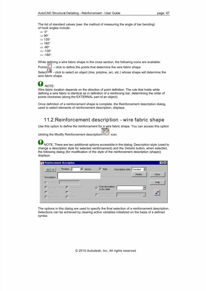
8/20/2019 Autocad Reinforcement Manual Eng
http://slidepdf.com/reader/full/autocad-reinforcement-manual-eng 104/222
AutoCAD Structural Detailing - Reinforcement - User Guide page: 97
The list of standard values (see: the method of measuring the angle of bar bending)of hook angles include:
⇒ 0° ⇒ 90° ⇒ 135° ⇒ 180°
⇒ -90° ⇒ -135° ⇒ -180°.
While defining a wire fabric shape in the cross section, the following icons are available:
Points – click to define the points that determine the wire fabric shape
Select - click to select an object (line, polyline, arc, etc.) whose shape will determine thewire fabric shape.
NOTE:Wire fabric location depends on the direction of point definition. The rule that holds while
defining a wire fabric is identical as in definition of a reinforcing bar: determining the order ofpoints clockwise (along the EXTERNAL part of an object).
Once definition of a reinforcement shape is complete, the Reinforcement description dialog,used to select elements of reinforcement description, displays.
11.2. Reinforcement description - wire fabric shape
Use this option to define the reinforcement for a wire fabric shape. You can access this option
clicking the Modify Reinforcement description icon.
NOTE: There are two additional options accessible in the dialog: Description style (used tochange a description style for selected reinforcement) and the Details button, when selected,the following dialog (for modification of the style of the reinforcement description (shape))displays:
The options in this dialog are used to specify the final selection of a reinforcement description.Selections can be achieved by clearing active variables initialized on the basis of a definedsyntax.
© 2010 Autodesk, Inc. All rights reserved

8/20/2019 Autocad Reinforcement Manual Eng
http://slidepdf.com/reader/full/autocad-reinforcement-manual-eng 105/222
page: 98 AutoCAD Structural Detailing - Reinforcement - User Guide
REMARKS:
• Description of a reinforcement shape is possible only for a single position, i.e. two ormore wire fabrics cannot be described simultaneously
• The Number edit field is used to enter the final number of wire fabrics that will beincluded directly in a table
• The Active option. If the option is selected, then the described reinforcement should be
considered in the reinforcement table. This option will be active by default, forreinforcement that is described for the first time. When the same reinforcement isdescribed for the second time, the option clears. In this way it is possible to prevent(when describing the same reinforcement twice) doubling the number of reinforcementelements calculated when preparing a reinforcement table; a description of active andnot active reinforcement may differ in a generated drawing – the options used for thispurpose are provided in the Descript ion of reinforcement shape dialog.
• In the case of the linear distribution, 2 different wire fabrics (with two different numbers)can be placed in a region; a description of the distributed wire fabric in cross-section,after its distibution is performed, shows a number of wire fabrics (see the drawing below);while modifying such a description of the wire fabric in cross section, it is possible to hideone of the wire fabrics (the Hide option should be used); the arrows allow switchingbetween two wire fabrics included in the distibution
• The fields: User description in the drawing and User description in the table enableadding any text to a reinforcement description (by entering it from the keyboard); thedescription will be presented correspondingly in drawings (included in wire fabricdescriptions in the drawing) and in the table (included only in the reinforcement table);since that moment the added text will be remembered (on the selection list) and you willbe able to use it later on; a text taken from the library of standard descriptions may also
be applied. These descriptions assume the style of the text describing the reinforcement.The user description is displayed in several lines; then the mechanisms accessible in AutoCAD® are applied. The user description together with an extension line and a labelmake up one object. Such an object may be edited (translated, rotated); to do that, firstuse the EXPLODE option.
© 2010 Autodesk, Inc. All rights reserved

8/20/2019 Autocad Reinforcement Manual Eng
http://slidepdf.com/reader/full/autocad-reinforcement-manual-eng 106/222
AutoCAD Structural Detailing - Reinforcement - User Guide page: 99
12. WIRE FABRIC DISTRIBUTION
12.1. Wire fabric distribution
Use this option to define wire fabric distribution. There are several ways to access this optionfrom:
• Menu: Reinforcement / Wire fabric distribution
• Ribbon: ASD - Reinforcement / Reinforcement - definition / Wire fabric distribution
• Toolbar: Definition - wire fabrics / Wire fabric distribution
• Command line: RBCR_NETD_RECT.Once the Wire fabric distribution option is selected, the following dialog displays:
The options in the left side of the dialog, in the Detailing parameters field, are used to specify atype of reinforcement distribution:- Linear (bar distribution along a selected line or indicated two points)- Varying linearly (this option is not available in the current program version).
The following parameters are defined for the selected distribution type:
• Justify – determines to which edge created wire fabrics will be justified:
– justify to 1st edge
– after selecting this option, one edit field for definition of a lap splice of wire fabrics isinaccessible; automatic lap splice lengths will be increased in such a way so that wirefabrics are justified to both edges without trimming wire fabric sheets
– justify to 2nd (opposite) edge• - refers to created 3D cross-sections; using it, you can position wire fabric bars in
the cross-section in accordance with the principles of projecting and making cross-sections; this way you can determine the side of the bar (beginning or end) on which theselected bar end types are provided.
You should also specify how a wire fabric is to be presented in distribution:
• top view
• side view
• as an indicated segment; once this option is selected, a selected bar is distributed,whereas the drawing of the distribution will present a selected segment of the bar in its
total dimension (in its current geometry).
© 2010 Autodesk, Inc. All rights reserved

8/20/2019 Autocad Reinforcement Manual Eng
http://slidepdf.com/reader/full/autocad-reinforcement-manual-eng 107/222
page: 100 AutoCAD Structural Detailing - Reinforcement - User Guide
The option at the bottom of the dialog is used to define a value of the lap splice of wire fabrics.
Click OK, to close the dialog. After indicating a line or two points, the defined distribution of thewire fabric is performed. The linear distribution will include at the most 2 different wire fabrics(two different wire fabric numbers).In a description of the distributed wire fabric in cross section, once its distribution is performed,
a number of wire fabrics is updated and another – additional label is provided (see the drawingbelow).
13. REINFORCEMENT DISTRIBUTION -REINFORCING BARS
13.1. Reinforcement distribution
This option is used to define the distribution of reinforcement. There are three ways to accessthis option from:
• Menu : Reinforcement / Reinforcement distribution
• Ribbon : ASD - Reinforcement / Reinforcement - definition / Reinforcement distribution
• Toolbar: Reinforcement - definition / Reinforcement distribution
• Command line: RBCR_DEF_BAR_DISTRIBUTION.The following dialog displays:
© 2010 Autodesk, Inc. All rights reserved

8/20/2019 Autocad Reinforcement Manual Eng
http://slidepdf.com/reader/full/autocad-reinforcement-manual-eng 108/222
AutoCAD Structural Detailing - Reinforcement - User Guide page: 101
The dialog is divided into three primary parts:On the left side of the dialog, in the Distribution type field, specify the type of reinforcementdistribution.
• linear - bar distribution along a selected line (e.g. the line of an element formwork) oralong two indicated points
• varying linearly - bar distribution within the region indicated (e.g. a formwork elementof variable height); the height of a bar being distributed will be adjusted automatically tothe formwork shape (prior to distribution, you can indicate reinforcement segmentswhose length changes during distribution)
• arc - bar distribution along the indicated arc
• along polyline - bar distribution along the indicated broken line (polyline)
• distribution: reinforcement as a point (bar in a section) - graphical representation of abar in a section
• any (all options in the right part of the dialog are not available); you can distribute aselected bar or bars; in the latter case, bars are distributed as a group.
Once the distribution type is selected, the method of reinforcement distribution is defined. Theonly exception constitutes the point reinforcement which requires neither defining a distributionmethod nor the direction of viewing the reinforcement. The following methods of reinforcementdistribution are available:
• zone method - a formwork element is divided into several regions (zones); in eachof the designated zones, you define reinforcement spacing independently
• module distribution - reinforcement spacing is defined by specifying the order ofspacing in the following form, e.g. 3x25, 5, 6x15, etc. with respect to the base point, andnext, with respect to the bar defined recently in the distribution
• Caquot distribution - a simplified method of reinforcement distribution which consistsin specifying the length of distribution as well as initial spacing and maximum spacing;
spacing values are calculated based on a simple method maintaining the spacing valuesobtained as a result of applying the method.
Finally, a manner of presenting the reinforcement distribution should be determined:
• top view
• side view
• as an indicated segment; once this option is activated, the selected bar is distributedand the distribution drawing shows the actual geometry of the chosen bar segment
• projection
• any.
Click OK; the dialog closes and reinforcement is distributed according to the definition.
For the distribution types: linear and varying linearly all the options provided in the dialog areavailable. For the distribution type: any, the distribution methods are inaccessible, whereas theviewing direction is available identically as in the case of the linear distribution.For the bar distribution as a point, both the methods and view direction are unavailable. Oncethe OK button is clicked, the Reinforcement - point dialog opens.The bottom part of the dialog displays the description of an option selected in the dialog.
© 2010 Autodesk, Inc. All rights reserved

8/20/2019 Autocad Reinforcement Manual Eng
http://slidepdf.com/reader/full/autocad-reinforcement-manual-eng 109/222
page: 102 AutoCAD Structural Detailing - Reinforcement - User Guide
NOTE:You can distribute several reinforcing bars simultaneously. After running the Reinforcementdistribution option, indicate several bars; a number of bars are recognized automatically anddistributed according to the adopted parameters defined (similarly as for a single bar) - see:Distribution of several bars simultaneously.
See also:Generation of distribution varying linearly and detailed table - example
13.2. Distr ibut ion of several bars simultaneously
The distribution of several bars simultaneously is possible only for the linear distribution.
Two bars distributed simultaneously are represented by one line whose length equals theheight of the larger stirrup.Distribution parameters are defined for a single bar. If distributed bars differ in diameter orsteel grade, then the fields for selection of these parameters will be blank. A description of a distribution of several bars simultaneously looks similar to that for adistribution of one bar. If different bars are distributed, then a description of the distribution willinclude all bar numbers (a number of descriptions will equal a number of distributed bars).
13.3. Linear distribution
After selecting the linear distribution , three distribution methods are accessible in theReinforcement distribution dialog:zonemoduleCaqout.
13.4. Linear distr ibution (zone)
To define the linear distribution, you need to determine 2 points or line with respect to whichthe reinforcement will be distributed. The side of a distribution segment the reinforcement ispositioned, depends on the segment sense. The rule of clockwise movement applies (asduring reinforcement definition).The distance between the bars being distributed and the distribution line is assumed by defaultto be the cover adopted from the bar shape. A direction of distribution is parallel to the defineddistribution line.Once the definition of zones is complete, the dialog opens; which is used to managedistribution within each of the defined zones.
Click (refers to created 3D cross-sections). Once selected, you can position reinforcingbars in the cross-section in accordance with the principles of projecting and making cross-sections. This way you can determine the side of the bar (beginning or end) on which theselected bar end types are provided.
© 2010 Autodesk, Inc. All rights reserved

8/20/2019 Autocad Reinforcement Manual Eng
http://slidepdf.com/reader/full/autocad-reinforcement-manual-eng 110/222
AutoCAD Structural Detailing - Reinforcement - User Guide page: 103
Distribution parameters are defined by:
• Specifying the value of reinforcement spacing in a given zone
• Determining the value of parameter n - it corresponds to the number of reinforcementspacings (NOTE: this value should nor be confused with a number of reinforcement barswhich equals n+1)
• Determining reinforcement area.If any of the parameters list changes, the values of the remaining parameters will be updated.The parameters listed above are illustrated by a schematic drawing provided in the dialog. Theoptions located next to the drawing enable you to position precisely the distribution ofreinforcement in a given zone:
• Two edit fields define the value of the distance between the extreme reinforcement barsand the zone limit
• The button placed between the edit fields enables centering the distribution
• The options located on both sides of the drawing (selection options) determine theelement from which the distance to the extreme reinforcement bars is measured (thismay be zone limit or adjacent reinforcement from the previous zone).
Command line
Select distribution type : [Linear / varying Linearly / Arc / Point] <Linear>
Distribution method : [Zone / Module / Caquot] < Zone >Direction of projection - viewing a bar [X / Y / Any / Segment] <Y>
Any – Determine direction of viewing a barSegment – Select bar segmentDialog box closing
Start distribution point or [ Line]End distribution point or [Back]
Beginning of 1 zone or [Side / Cover / Angle / N-zones / Back]Cover <5.5> : 6
AngleReinforcement inclination angle [Select / Points] <90>
Number of zones <1> : 3
End of 1 zone or [Back]
End of 2 zone or [Back]
Next zone or change [Spacing / Number / Alignment ]Spacing <0.12> : 0.18Number <7> : 6
Alignment: [Center / Left / Right] <Center>
© 2010 Autodesk, Inc. All rights reserved

8/20/2019 Autocad Reinforcement Manual Eng
http://slidepdf.com/reader/full/autocad-reinforcement-manual-eng 111/222
page: 104 AutoCAD Structural Detailing - Reinforcement - User Guide
13.5. Linear distribution (module)
To define the linear distribution, you should determine 2 points or lines with respect to whichthe reinforcement will be distributed. The side of a distribution segment the reinforcement ispositioned, depends on the segment sense. The rule of clockwise movement applies (asduring reinforcement definition).
The distribution is carried out only along the length of a segment defined. The distribution startpoint corresponds to the first point indicated while defining a segment or to the closest pointduring definition with the use of a line. All operations are carried out ONLY along a selected line within the distribution region.The modular distribution starts with defining a position of a first bar to be distributed (theposition may be determined graphically or by entering the value from the keyboard). A unit ofthe value entered is the unit of the AutoCAD® Structural Detail ing set in preferences. Whiledefining distribution, the following options are available:
• Direction - changes the direction of distribution to the opposite
• Mirror - provides mirror reflection of the distribution already carried out
• Insert between - when distribution is carried out on one side and then the directionchanges and the reinforcement is distributed on the other side, you can introduce the
reinforcement in the area between these both distributions defining maximal spacing ornumber of bars.
Command line
Select distribution type: [Linear / varying Linearly / Arc / Point] <Linear> :
Distribution method: [Zone / Module / Caquot] < Module>Direction of projection - viewing a bar [X /Y/ Any/ Segment ] <Y>
Any – Determine direction of viewing a barSegment – Select bar segment
Dialog box closing
Start distribution point or [ Line]End distribution point or [Back]Position of first bar or [Side / Direction / Cover / Attachment / Cover ] <5>:
Cover <5.5> : 6 AngleReinforcement inclination angle [Select / Points] <90>
<Number> x <Spacing> or [Direction / Insert between / Mirror / Back]Insert betweenEmax or [Number]Defined spacing = 22.23 cm
End or [+1 / -1 / Back ]
13.6. Linear distr ibution (Caquot)
Distribution is ALWAYS symmetrical with respect to the length of a segment in whichdistribution is performed. The designations:L - length of a segment of distributions1- initial spacingSmax - maximum spacingn = L/2 - spacing module rounded upwards to a whole valueso =s1/2 - position of the first point at the beginning and end of a distribution line.
The set of available CAQUOT spacing values includes: 7, 9, 11, 13, 16, 20, 25, 35, 60 cm
© 2010 Autodesk, Inc. All rights reserved

8/20/2019 Autocad Reinforcement Manual Eng
http://slidepdf.com/reader/full/autocad-reinforcement-manual-eng 112/222
AutoCAD Structural Detailing - Reinforcement - User Guide page: 105
Command line
Select distribution type : [Linear / varying Linearly / Arc / Point] <Linear>
Distribution method : [Zone / Module / Caquot] < Caquot>Direction of projection - viewing a bar [X / Y / Any / Segment] <Y>
Any – Determine direction of viewing a barSegment – Select bar segment
Dialog box closing
Start distribution point or [select Line]End distribution point or [Back]Initial spacing or [Side / Cover / Back ] <9>Maximum spacing <35>
13.7. Distr ibution varying linearly
After selecting the linear distribution , three distribution methods are accessible in theReinforcement distribution dialog:zonemoduleCaqout.
See also:Generation of distribution varying linearly and detailed table - example
13.8. Distr ibution varying linearly (zone)
After defining the linear distribution, you should determine bar segments whose lengthchanges in the course of distribution as follows :
• Cut (with a line) through the bar segments, thus indicating that their length is to bevariable in the course of distribution.
• Define a region of reinforcement distribution and a cover value (by default, it is adoptedfrom a bar shape) have to be defined.
A direction of reinforcement distribution are defined by indicating:- 2 points- contour edge.By default, the distribution direction is parallel to 1 defined distribution line (region edge) - it ispresented by means of two arrows.
In the next stage, the distribution region is divided into zones. If definition of zones is
completed, then the dialog box opens, and is used to manage distribution within each of thedefined zones.
When the distribution varying linearly is applied, it is necessary to define a region. There arethree methods available: Select, Pick point and X-points.For the X-points method, the region is defined by means of a closed broken line. By default,first two indicated points will determine the distribution line.When applying Selection (select), a selected edge will be the distribution line (the closestedge, if it is selected by means of a window); it works similarly when the Pick point option isselected: the closest edge from the indicated point is the distribution line.Once the region is identified, the program draws a CONTOUR of the distribution region with acover included. Points (zone boundaries) may be indicated only within the distribution region. A cover is ALWAYS defined as the distance measured from reinforcement, and perpendicular
to the distribution line. The zone length is ALWAYS measured along the distribution line.
© 2010 Autodesk, Inc. All rights reserved
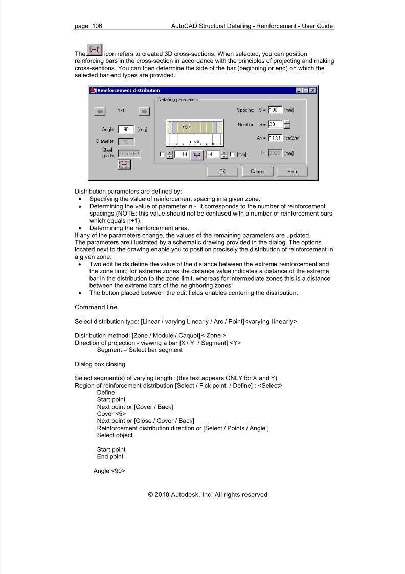
8/20/2019 Autocad Reinforcement Manual Eng
http://slidepdf.com/reader/full/autocad-reinforcement-manual-eng 113/222
page: 106 AutoCAD Structural Detailing - Reinforcement - User Guide
The icon refers to created 3D cross-sections. When selected, you can positionreinforcing bars in the cross-section in accordance with the principles of projecting and makingcross-sections. You can then determine the side of the bar (beginning or end) on which theselected bar end types are provided.
Distribution parameters are defined by:
• Specifying the value of reinforcement spacing in a given zone.
• Determining the value of parameter n - it corresponds to the number of reinforcementspacings (NOTE: this value should not be confused with a number of reinforcement barswhich equals n+1).
• Determining the reinforcement area.If any of the parameters change, the values of the remaining parameters are updated.The parameters are illustrated by a schematic drawing provided in the dialog. The optionslocated next to the drawing enable you to position precisely the distribution of reinforcement ina given zone:
• Two edit fields define the value of the distance between the extreme reinforcement andthe zone limit; for extreme zones the distance value indicates a distance of the extremebar in the distribution to the zone limit, whereas for intermediate zones this is a distancebetween the extreme bars of the neighboring zones
• The button placed between the edit fields enables centering the distribution.
Command line
Select distribution type: [Linear / varying Linearly / Arc / Point] <varying linearly>
Distribution method: [Zone / Module / Caquot] < Zone >Direction of projection - viewing a bar [X / Y / Segment] <Y>
Segment – Select bar segment
Dialog box closing
Select segment(s) of varying length : (this text appears ONLY for X and Y)Region of reinforcement distribution [Select / Pick point / Define] : <Select>
DefineStart pointNext point or [Cover / Back]Cover <5>Next point or [Close / Cover / Back]Reinforcement distribution direction or [Select / Points / Angle ]Select object
Start point
End point
Angle <90>
© 2010 Autodesk, Inc. All rights reserved

8/20/2019 Autocad Reinforcement Manual Eng
http://slidepdf.com/reader/full/autocad-reinforcement-manual-eng 114/222
AutoCAD Structural Detailing - Reinforcement - User Guide page: 107
Beginning of 1 zone or [N-zones / Back]Number of zones <1>End of 1 zone or [Back]End of 2 zone or [Back]
Next zone or change [Spacing / Number / / Alignment ]Spacing <0.12>Number <7>
Alignment: [Center / Left / Right] <Center>
13.9. Distr ibution varying linearly (module)
After defining the linear distribution, you should determine bar segments whose lengthchanges in the course of distribution as follows :
• Cut (with a line) through bar segments, thus indicating that their length is to bevariable in the course of distribution.
• Define a region of reinforcement distribution and a cover value (by default, it isadopted from a bar shape).
A direction of reinforcement distribution are defined by indicating:- 2 points- contour edge.By default, the distribution direction is parallel to 1 distribution line defined (region edge) - it ispresented by means of two arrows.
Next, you should determine a bar attachment point (by default, the bar is attached in thedistance equal to the cover value defined for a bar shape). The distribution start pointcorresponds to the first point indicated while defining a segment or to the closest point if theline is selected. A region is defined and the distribution line is assumed in the identical manner as in case of
the distribution varying linearly (zone distribution).Once the region is defined, a contour with a representative bar is drawn. This bar is attachedto the cursor and responds to changes in its position. The cursor may move only along thedistribution line and determines the position of a newly-defined bar.The modular distribution starts with defining a position of a first bar to be distributed (theposition may be determined graphically or by entering the value from the keyboard). A unit ofthe value entered is the unit as specified in the program preferences. While definingdistribution, the following options are available:
• Direction - changes the direction of distribution to the opposite
• Mirror - provides mirror reflection of the distribution already carried out
• Insert between - when distribution is carried out on one side and then the directionchanges and the reinforcement is distributed on the other side, you should introduce the
reinforcement in the area between these both distributions defining maximal spacing ornumber of bars.
Command line
Select distribution type: [Linear / varying Linearly / Arc / Point] <varying Linearly>
Distribution method : [Zone / Module / Caquot] < Module>Direction of projection - viewing a bar [X / Y / Segment] <Y>
Segment - Select bar segment
Dialog box closing
Select segment(s) of varying length : (this text appears ONLY for X and Y)Region of reinforcement distribution [Select / Pick point / Define] : <Select>
© 2010 Autodesk, Inc. All rights reserved

8/20/2019 Autocad Reinforcement Manual Eng
http://slidepdf.com/reader/full/autocad-reinforcement-manual-eng 115/222
page: 108 AutoCAD Structural Detailing - Reinforcement - User Guide
DefineStart point
Next point or [Cover / Back]Cover <5>
Next point or [Close / Cover / Back]Reinforcement distribution direction or [Select / Points / Rotation]
select object
Start pointEnd point
Angle <90>
Position of first bar or [Direction ] <5><Number> x <Spacing> or [Direction / Mirror / Insert between / Back]
Insert betweenEmax or [Number]
Defined spacing
End or [+1 / -1 / Back ]
13.10. Distribution varying linearly (Caquot)
The distribution type is defined identically as the linear distribution. Only a contour with adistribution line displays.
13.11. Generation of distribution varying linearlyand detailed table
The definition of distribution varying linearly of transversal reinforcement for a tapered beam isdisplayed below. For such reinforcement distribution a detailed table is prepared.
To obtain reinforcement distribution shown in the drawing, you should:
• Define transversal and longitudinal beam section (as in the figure below) using the optionsavailable in AutoCAD® (rectangle, line)
© 2010 Autodesk, Inc. All rights reserved

8/20/2019 Autocad Reinforcement Manual Eng
http://slidepdf.com/reader/full/autocad-reinforcement-manual-eng 116/222
AutoCAD Structural Detailing - Reinforcement - User Guide page: 109
• Define transversal reinforcement in the beam cross section as follows :
- Click (Reinforcement – cross-section).
- In the dialog, click , and click (Diagonal).
- Indicate the top left and bottom right corners of the rectangle designating the crosssection.- In the Reinforcement description dialog, click OK (acceptance of the defaultdescription).- Select the description position in the drawing (see the figure below)
• Click (Reinforcement distribution) (the definition of reinforcement distribution begins;varying linearly).
• Indicate the stirrup (defined earlier) and click ENTER; the Reinforcement detailing dialogopens; the following options are selected in the dialog:
- Distribution TYPE: varying linearly (press the icon)
- Distribution METHOD: zone (press the icon)
- Viewing DIRECTION: press the icon- Click OK.
• Determine successive reinforcement segments (in this case, these are vertical legs of thestirrup) whose length changes in the course of distribution - see the figure underneath.
• Select the beginning point and successive points within which the varying distribution is tobe contained; indicate one by one the points: 1, 2, 3, 4 and finally indicate 1 again; clickENTER.
© 2010 Autodesk, Inc. All rights reserved

8/20/2019 Autocad Reinforcement Manual Eng
http://slidepdf.com/reader/full/autocad-reinforcement-manual-eng 117/222
page: 110 AutoCAD Structural Detailing - Reinforcement - User Guide
• Determine the direction of distribution; click ENTER.
• Select the beginning and end of the zone (begining and end of the beam, if the distributionconcerns the whole beam); click ENTER.
• Click OK in the Reinforcement detailing and the Reinforcement descript ion dialogs –default values will be adopted.
• Indicate the position of reinforcement description and click ENTER (see the figure below).
To create a detailed table for the reinforcement distribution (varying linearly) as defined above:
• Click (Bars - Detailed table).
• Indicate the generated reinforcement distribution (varying linearly).
• Select the location of the detailed table.
13.12. Arc distribution
This option defines the linear distribution along a defined / indicated part of an arc; thedistribution along an arc is an extension of the linear distribution - this is the reason why adistribution angle is not defined.
Reinforcing bars in distribution are perpendicular to the distribution lineTo define a distribution region along an arc, (see the drawing below):
1. Indicate a curve defined using AutoCAD® options or indicate the position of threesuccessive points belonging to an arc
2. Indicate the distribution line; there are three locations of the distribution line possible:inner, middle and outer.
For the indicated distribution line bars in the distribution are arranged according to theparameters adopted in the dialog box.
NOTE:The location of the distribution line may be changed.
© 2010 Autodesk, Inc. All rights reserved

8/20/2019 Autocad Reinforcement Manual Eng
http://slidepdf.com/reader/full/autocad-reinforcement-manual-eng 118/222
AutoCAD Structural Detailing - Reinforcement - User Guide page: 111
A description of the distribution is an arc-shaped line as for the radial distribution. This linealways shows the spacing from the distribution line.
Four types of the line describing this distribution are possible:
-
-
-
- .First two descriptions are arc-shaped lines, the latter are for straight distributions.
Command line
Select distribution type: [Linear / varying Linearly / Arc / Point] <Arc> :
First point of distribution or [Circle / Select] :
Circle - a circle is selected as a basis for the arc distribution
Select - successive three points belonging to an arc are indicated
Second point of distribution [Side]
Third point of distribution [Side]
Select location of distribution line
Beginning of zone [Side / Cover / N-zones]
End of zone [Back]
13.13. Distribution along the polyline
Linear distribution can be specified along a defined / selected broken line (polyline).Distributed reinforcing bars are placed perpendicular to the distribution line.
One reinforcement distribution zone is generated for each segment of a broken line. Thedistribution of reinforcement is described by one description line.
You can modify this reinforcement distribution type exactly as the zone distribution.
© 2010 Autodesk, Inc. All rights reserved

8/20/2019 Autocad Reinforcement Manual Eng
http://slidepdf.com/reader/full/autocad-reinforcement-manual-eng 119/222
page: 112 AutoCAD Structural Detailing - Reinforcement - User Guide
13.14. Reinforcement distribution - along polyl ine
The Reinforcement detailing dialog displays after you define the basic parameters ofreinforcement distribution. A cover ALWAYS denotes the distance measured from thereinforcement and perpendicular to the distribution line. The zone length is ALWAYSmeasured along the distribution line.
Click , to position reinforcing bars in the cross-section in accordance with the principlesof projecting and making cross-sections; this way you can determine the side of the bar(beginning or end) on which the selected bar end types are provided.
You can define the distribution parameters by:
• Defining the reinforcement spacing in a given zone.
• Specifying a value of the n parameter - it corresponds to the number of reinforcementspacing (NOTE: Do not confuse this value with the quantity of reinforcement elementswhich is n+1).
• Specifying the reinforcement area.
Changing any of the parameters listed above will update the values of the remainingparameters.The schematic drawing in the dialog illustrates the above-mentioned parameters. The optionsnext to the drawing you are used to precisely position the reinforcement distribution in a given
zone:
© 2010 Autodesk, Inc. All rights reserved

8/20/2019 Autocad Reinforcement Manual Eng
http://slidepdf.com/reader/full/autocad-reinforcement-manual-eng 120/222
AutoCAD Structural Detailing - Reinforcement - User Guide page: 113
• Use the two edit fields to specify the distance between the extreme reinforcement andthe zone border; for extreme zones, the distance value denotes the distance from the
e zones it is the distance
ution.
The
extreme bar in the distribution to the zone border, while for middlbetween the extreme bars of adjacent zones.
• Use the button between the edit fields to center the distrib
following icons are located on the right side of the dialog:
Insert - inserts a reinforcing bar at the selected location
Insert between - inserts a reinforcing bar between 2 selected reinforcing bars
Move - moves a reinforcing bar; you should specify a translation vector
Delete - deletes a selected reinforcing bar.
tribution of bar:
e to be associated with the
ialog displays where you can specifyarameters of the distribution description. The options for the distribution description are the
same as for the description of point reinforcement.
INFORCEMENT DISTRIBUTION -
urs (e.g. RC slab). There
einforcement / Surface reinforcement - wire fabrics
• Ribbon: ASD - Reinforcement / Definition - reinforcement / Surface reinforcement - wire
• r: Definition - wire fabrics / Surface reinforcement - wire fabrics
13.15. Any distribution After selecting the any distribution of bars, the Reinforcement detailing dialog closes.
To define the any dis
• select the base point of distribution (this point does not havselected bar)
• select the attachment (insertion) point for the distribution.
Click Enter to finish defining the distribution.
After completing a definition of the distribution, the dp
14. SURFACE REWIRE FABRICS
14.1. Surface reinforcement - wire fabricsUse this option to define the distribution of wire fabrics for 2D contoare several ways to access this option from:
• Menu: R
fabrics
Toolba
• e: RBCR_NETD_RECT.Command lin
NOTE: A total num er of wire fabrics (panels) is calculated; cuttings obtained while trimming wireb
ics are nofabr t considered in reinforcement tables.
NOTE:Databases of wire fabrics (*.xml files) used in the surface distribution are available. Forexample, the file name for the British code, is fabric_BS.xml (after the part ‘fabric’, the name othe code ch
fosen in the Job preferences is added). Database files are available in the DATA
folder. Wire fabric databases can be modified in order to adapt wire fabric parameters based
on use.
© 2010 Autodesk, Inc. All rights reserved

8/20/2019 Autocad Reinforcement Manual Eng
http://slidepdf.com/reader/full/autocad-reinforcement-manual-eng 121/222
page: 114 AutoCAD Structural Detailing - Reinforcement - User Guide
After selecting the Surface reinforcement - wire fabrics option, the following dialog displays:
NOTE: A defined contour is a common contour for generation of reinforcing bar distribution and wirefabric distribution (bar distribution is generated in the contour for wire fabrics and vice versa).
The dialog is divided into three main parts:The left side of the dialog contains four icons which specify the type of distribution:
- Distribution A - wire fabric distribution within a span (within the defined contour e.g.plate span or wall)
- Distribution B - wire fabric distribution above the intermediate support (with respect tothe support axis)
- Distribution C - wire fabric distribution above the extreme support (along the supportedge)
- Distribution D - any manner of wire fabric distribution (without the necessity to define acontour) without trimming wire fabrics.
There are two modes of defining surface distribution available:
• Automatic mode – an indicated contour is detected automatically and wire fabrics aretrimmed to fit the contour
• Manual mode – wire fabrics are distributed manually and timmed automatically to fit thecontour.
For both modes, identical methods of wire fabric definition are available.
In the middle of the dialog, the parameters used to define a selected distribution type areavailable:Distribution A The top of the dialog includes options used to define the distribution region or opening(s);there are edit fields available used to define values of cover for wire fabrics and support width.When starting definition of a distribution contour, the Opening option is inaccessible, whereasthe Distribution region option is active and selected. Once the contour definition is complete,the Distribution region option is no longer active, whereas the Opening option becomes activeand selected. You can then define an opening contour within the earlier-defined contour; anumber of openings are determined.Distribution B The following options are available:
• Edit field used to define the support width• Edit fields used to define the value informing how far the wire fabric extends outside thesupport face (in both directions).
© 2010 Autodesk, Inc. All rights reserved
8/20/2019 Autocad Reinforcement Manual Eng
http://slidepdf.com/reader/full/autocad-reinforcement-manual-eng 122/222
AutoCAD Structural Detailing - Reinforcement - User Guide page: 115
Distribution C The following options are available:
• Edit field used to define the cover value for wire fabrics
port width
ire fabric extends outside the
iddle of the dialog are inaccessible.
• Contour within which wire fabric is to be distributed is an external contour of a slab orls the support (wall) – within the support
ingB or C), they are recognized automatically.
istribution:
• Edit field used to define the sup
• Edit field used to define the value informing how far the wsupport face.
Distribution D The options in the m There are two reasons for defining support width:
wall; definition of a support width value moderegion a wire fabric will not be generated
• After determining the support width, overhangs are defined automatically – when definreinforcement above supports (distribution
The right side of the dialog contains several icons used to specify a region of wire fabricdfor Distribution A
- Select (selects diexisting defined dis
rectly a region defined as rectangle, polygon, circle or indicates thetribution region)
- Pick point (indicates an internal point for a closed region; as a result of the operation,region contour is detected)
the
- Diagonal (determines rectangular region by means of defining its diagonal)
- Region (defines closed region by means of a broken line)
- Delete opening (allows deleting an earlier-defined opening contour)
for Distribution B and C
- Select (selects directly one edge of a region defined as line or support)
- 2 Points (indicates two points determining the axis of a rectilinear support)
In ) whichform how far a wire fabric extends outside the support face.
ons are inaccessible. Click OK, to switch to distribution definition (without definition of a
the dialog, you can define dimensions (apart from a cover value and width supportin for Distribution D Icregion).
NOTE:If distribution A, B or C is selected, then it is required to define a region in which wire fabricswill uted; therefore, the OK button is unavailable until the region is defined. The
and
e Wire fabric distribution – manual mode or the Wire fabricistribution – automatic mode dialog opens.
xample of definition of wire fabric surface distribution
be distrib
necessity of defining the region is imposed by the subsequent mode of wire fabric definition;wire fabrics distributed one by one are moved to the edges of a defined region or trimmedadjusted to the region contour.
Once the OK button is clicked, thdThe bottom of the dialog displays a description of the option selected.
See also:E
© 2010 Autodesk, Inc. All rights reserved

8/20/2019 Autocad Reinforcement Manual Eng
http://slidepdf.com/reader/full/autocad-reinforcement-manual-eng 123/222
page: 116 AutoCAD Structural Detailing - Reinforcement - User Guide
14.2. Wire fabric distribution - manual mode
After choosing the manual mode of wire fabric definition and clicking OK in the Surfacereinforcement distribution – wire fabrics dialog, the following dialog displays:
The options available in the dialog are used to parametrize distribution in the region defined:
• In the Wire fabric field, you select a wire fabric type from the list; contents of the listdepend on the RC code selected in the Job preferences dialog (similarly as forreinforcing bars); once the wire fabric type is selected, the fields are filled automaticallywith data from the fabric_xxxx.xml file (where xxxx stands for a name of wire fabricdatabase) located in the DATA folder.NOTE: You can modify the wire fabric database or add user-defined types of wire fabricsin the file of wire fabric database - new records have to be given identical descriptions asrecords existing in the database:Wire fabric coverL and l - total dimensions of a wire fabric sheet (the dimensions may only be decreased -they cannot be increased)R and r - lap slices; these dimensions are ascribed to a given wire fabric and saved in thewire fabric database
• In the Distribution parameters field the following options are available: Angle - the selection list containing angle values (the angle value may be changed);
clicking enables reading the inclination angle of the indicated edge of a regioncontour directly from a drawingNumber of sheets- use this option to insert simultaneously several wire fabric sheets; if a
number of sheets is greater than 1, then the following become accessible: and(they are used to determine how the sheets are to be positioned with respect to eachother) Number of layers - information only for the needs of the subsequent wire fabrictableLocation (top/internal, bottom/external) - parameter describing location of wire fabrics; itaffects graphical representation of wire fabrics (see Job preferences).
© 2010 Autodesk, Inc. All rights reserved

8/20/2019 Autocad Reinforcement Manual Eng
http://slidepdf.com/reader/full/autocad-reinforcement-manual-eng 124/222
AutoCAD Structural Detailing - Reinforcement - User Guide page: 117
14.3. Wire fabric distribution - automatic mode
After choosing the automatic mode of wire fabric definition and clicking OK, the Surfacereinforcement distribution – wire fabrics dialog displays:
The options contained in the dialog are used to parametrize distribution in the region defined:
• In the Wire fabric field, you select a wire fabric type from the list; contents of the listdepend on the RC code selected in the Job preferences dialog (similarly as forreinforcing bars); once the wire fabric type is selected, the fields are filled automaticallywith data from the fabric_xxxx.xml file (where xxxx stands for a name of wire fabricdatabase) located in the DATA folder.NOTE: You can modify the wire fabric database or add user-defined types of wire fabricsin the file of wire fabric database - new records have to be given identical descriptions asrecords existing in the database:Wire fabric coverL and l - total dimensions of a wire fabric sheet (the dimensions may only be decreased -they cannot be increased)R and r - lap slices; these dimensions are ascribed to a given wire fabric and saved in thewire fabric database
• In the Distribution parameters field the following options are available: Angle - the selection list containing angle values (the angle value may be changed);
clicking enables reading the inclination angle of the indicated edge of a regioncontour directly from a drawingDirection – indicates the contour side from which wire fabric distribution will start; clicking
enables changing the direction wire fabric distribution; the side from which wire fabric
distribution will begin, is identified in a drawing by means of the symbol Align – determines the side with respect to which the generated wire fabrics will bealigned:
– aligns to 1st edge – after selecting this option, one edit field for defining a lap splice of wire fabrics
becomes inaccesible; it means that lap splice lengths will be increased automatically insuch a manner so that wire fabrics are aligned on both sides without the necessity to trimwire fabric sheets
– aligns to the 2nd (opposite) edge
- aligns to both edges; after you select this option, the edit fields for defining the lapsplice of wire fabrics become inaccessible
After selecting the Diagonal option, the location of the diagonal changes in the wire fabricdistribution (if the diagonal is displayed in the distribution)
Number of layers - information only for the needs of the subsequent wire fabric table
Location (top/internal, bottom/external) - parameter describing location of wire fabrics; itaffects graphical representation of wire fabrics.
© 2010 Autodesk, Inc. All rights reserved

8/20/2019 Autocad Reinforcement Manual Eng
http://slidepdf.com/reader/full/autocad-reinforcement-manual-eng 125/222
page: 118 AutoCAD Structural Detailing - Reinforcement - User Guide
Grouping – if this option is selected, then wire fabrics of identical parameters positionednext to each other (i.e. with their edges touching) are presented as one object; it is anoperation aimed at improving transparency and readability of a whole drawingType – allows selecting one out of three possibilities:normal type – shown in the drawing below
passing and half-way types - wire fabrics are shifted in relation to each other by half thelength (to avoid concentration of lap splices of several wire fabrics at the same point) –shown in the drawings below
half-way type
© 2010 Autodesk, Inc. All rights reserved

8/20/2019 Autocad Reinforcement Manual Eng
http://slidepdf.com/reader/full/autocad-reinforcement-manual-eng 126/222
AutoCAD Structural Detailing - Reinforcement - User Guide page: 119
passing type
There is also a possibility of simplified presentation of wire fabrics; the drawing belowshows the simplified method of presenting a generated wire fabric.
© 2010 Autodesk, Inc. All rights reserved

8/20/2019 Autocad Reinforcement Manual Eng
http://slidepdf.com/reader/full/autocad-reinforcement-manual-eng 127/222
page: 120 AutoCAD Structural Detailing - Reinforcement - User Guide
14.4. Example of definit ion of wire fabric surfacedistribution
The following drawing illustrates the surface distribution of wire fabrics in a slab.
To define the surface distribution of wire fabrics in a slab, follow these steps:
1. Click the Surface reinforcement - wire fabrics icon2. Specify the parameters listed below:
- wire fabric distribution: automatic
- distribution type:- support width = 250 mm- cover = 30 mm
3. Click Pick point, and indicate a point located within the slab contour4. Select the Distribution region option and click OK.5. In the Distribution dialog, specify the parameters listed below:
Wire fabric field:type: B196lap splices: R = 450 mm, r = 300 mm
Distribution parameters field:angle = 90location: top/internal
align: to 1st edgetype: normalGrouping option: switched offnumber of layers: 1
6. Click Add; the generated surface distribution of wire fabrics is shown in the drawingbelow (a summary table for wire fabrics has been added; view the table by clicking theicon
Wire fabrics - summary table ).
© 2010 Autodesk, Inc. All rights reserved

8/20/2019 Autocad Reinforcement Manual Eng
http://slidepdf.com/reader/full/autocad-reinforcement-manual-eng 128/222
AutoCAD Structural Detailing - Reinforcement - User Guide page: 121
15. SURFACE REINFORCEMENT DISTRIBUTION -BARS
15.1. Surface reinforcement - barsUse this option to define reinforcement distribution for reinforcing bars for 2D contours (e.g.wall or RC slab). There are three ways to access this option from:
• Menu: Reinforcement / Surface reinforcement - bars
• Ribbon: ASD - Reinforcement / Reinforcement - definition / Surface distribution - bars
• Toolbar: Definition - bars / Surface reinforcement - bars
• Command line: RBCR_DEF_BAR_SURF.
© 2010 Autodesk, Inc. All rights reserved

8/20/2019 Autocad Reinforcement Manual Eng
http://slidepdf.com/reader/full/autocad-reinforcement-manual-eng 129/222
page: 122 AutoCAD Structural Detailing - Reinforcement - User Guide
Once activated, the following dialog displays:
NOTE:There are available databases of reinforcing bars (*.xml files) used in the surface distribution.The file name, for example for the British code, is bar_BS 8666_2000.xml (after the part ‘bar’,the name of the code chosen in the Job preferences is added). Bar databases can be modifiedin order to adapt bar parameters.
While defining distribution, an object contour (e.g. plate, wall with supports) is generated as aclosed external contour. Into the defined region objects such as supports or unsupportededges are introduced. You can define (or remove) an opening in a defined region.
NOTE:
A defined contour is a common contour for generation of reinforcing bar distribution and wirefabric distribution (bar distribution may be generated in the contour for wire fabrics and viceversa).
There are two reasons for defining support width:
• Contour within which reinforcement is distributed is an external contour of a slab or wall;definition of a support width value models the support (wall) – within the support regionreinforcement distribution will not be generated
• After determining the support width, automatically overhangs are defined – when definingreinforcement above supports (distribution B or C), they are recognized automatically.
The dialog is divided into three main parts:
The left side of the dialog contains four icons which determine the type of distribution (type ofregion):
- Distribution A – surface distribution of bars within a defined contour (e.g. span of slabor wall)
- Distribution B – surface distribution of bars above the intermediate support (withrespect to the support axis)
- Distribution C - surface distribution of bars above the extreme support (along thesupport edge).
- Distribution D - surface distribution of bars within a defined contour (a distributionregion is defined as distribution A, whereas bars are distributed radially (‘fan-shaped’arrangement) between both edges).
© 2010 Autodesk, Inc. All rights reserved

8/20/2019 Autocad Reinforcement Manual Eng
http://slidepdf.com/reader/full/autocad-reinforcement-manual-eng 130/222
AutoCAD Structural Detailing - Reinforcement - User Guide page: 123
The middle of the dialog includes parameters which are indispensable while defining aselected distribution type:
Distribution A The top of the dialog contains options to define a distribution region or opening(s); additionally,there are edit fields available to define support width values and reinforcement cover.
When defining a contour of reinforcement distribution, the Opening option is inaccessible,whereas the Distribution region option is active and selected. Once definition of a contour iscompleted, the Distribution region option is no longer active, whereas the Opening optionbecomes active and selected. You may define an opening contour within the earlier-definedcontour; a number of openings are determined.Distribution B The following options are provided in the middle of the dialog:
• Edit field defines support width
• Edit field defines a value indicating how far the reinforcement extends outside thesupport face (in both directions).
Distribution C The following options are provided in the middle of the dialog:
• Edit field defines a reinforcement cover value
• Edit field defines support width• Edit field defines a value indicating how far the reinforcement extends outside the
support face.Distribution D Definition of a distribution region is similar to Distribution A, assuming that the radialdistribution is distribution in one zone; bars are distributed radially (‘fan-shaped’ arrangement)between two edges. The bar spacing is constant only in one line (referred to as a distributionline).
The right of the dialog contains several icons used to choose the mode of graphical definitionof distribution. The number of icons depends on a selected type of surface distribution.for Distribution A
- Select (direct selection of a region defined as rectangle, polygon, circle or indication of anexisting region)
Command line:Select objectDistribution direction
Select / 2Points
where:select object – indicates an object defining the contour of distribution regionselect – indicates the contour side determining distribution direction2Points – indicates 2 points that determine distribution direction
- Pick point (indicates an internal point of a closed region; as a result of the operation, theregion contour is detected)
Command line:Pick object internal pointDistribution direction
Select / 2Points
where:object internal point – indicates a point positioned within the object defining a contourselect – indicates the contour side determining distribution direction2Points – indicates 2 points that determine distribution direction
- Diagonal (defines a rectangular region by determining its diagonal)
© 2010 Autodesk, Inc. All rights reserved

8/20/2019 Autocad Reinforcement Manual Eng
http://slidepdf.com/reader/full/autocad-reinforcement-manual-eng 131/222
page: 124 AutoCAD Structural Detailing - Reinforcement - User Guide
Command line:First cornerSecond cornerDistribution direction
Select / 2Points
where:first, second corner – defines the opposite apexes of a rectangle defining the contourselect – indicates the contour side determining distribution direction2Points – indicates 2 points that determine distribution direction
- Region (defines a closed region by means of a broken line) – in this definition modesupports with different width values on contour edges may be defined
Command line:First pointNext points [Cover / Support width]Distribution direction
Select / 2Points
where:first, second, …, next point – defines apexes of a polygon defining the contourcover – determines cover values for each contour edge separatelysupport width – determines support width values for each contour edge separatelyselect – indicates the contour side determining distribution direction2Points – indicates 2 points that determine distribution direction
- Delete opening (allows deleting an earlier-defined opening contour)
for Distribution B and C
- Select (selects directly one edge of a contour defined as line or support)
Command line:Select supportContinue or change [Side / Support width / First overhang / Second overhang]
where:select support – indicates a line denoting support of a slab or wallside – determines on which support side reinforcement is to be located (refers to distributionC)support width – determines a support width valuefirst and second overhang – determines an overhang value on both sides of the support (fordistribution C – on one side of the support)
- 2 Points (indicates two points determining the axis of a rectilinear support)
Command line:Select first pointSelect second point or [Side / Support width / First overhang / Second overhang]
where:first and second point – indicates first and second point of a line denoting the support of a slabor wallside – determines on which support side reinforcement is to be located (refers to distributionC)
support width – determines a support width value
© 2010 Autodesk, Inc. All rights reserved

8/20/2019 Autocad Reinforcement Manual Eng
http://slidepdf.com/reader/full/autocad-reinforcement-manual-eng 132/222
AutoCAD Structural Detailing - Reinforcement - User Guide page: 125
fidistribution C – on one side of the support)rst and second overhang – determines an overhang value on both sides of the support (for
g, define dimensions (apart from a cover value and support width) for the distance
at the reinforcement extends outside the support face. One or more supports may be
r Distribution D cated in the right-hand side of the dialog is identical as for distribution A.
line:ection [Select / 2Points]
second edgen of a distribution line (when determining the location of a description)
w
ins these points, which at the same
oins the centers of
he radial (‘fan-shaped") distributionlocation of a distribution line – a dimension line of the distribution description which shows a
elow are presented elements needed to define the radial (‘fan-shaped") distribution for anexample contour with the distribution.
Furthermore, for distribution C it should be determined on which side of a support thereinforcement is to be located.In the dialo
thselected.
foThe list of icons lo CommandDistribution dir
first edge
locatio
here:
distribution direction:2 points – after indicating the points, a line is drawn that jotime is the line of constant distribution; bars are distributed radially (‘fan-shaped’arrangement) between two edges intersected by this lineselect – indicate two edges; once they are selected, a line is drawn that jthese edges, which at the same time is the line of constant distribution of bars.First, second edge – lines that limit t
bar spacing in the distribution line.
B
Click ment: definition and detailing dialog displays.OK, the Reinforce
NOTE:For surface distribution of a bar, a DETAILED table is also available: table with total numbers
of reinforcing bar consumption split into individual bar diameters.
© 2010 Autodesk, Inc. All rights reserved

8/20/2019 Autocad Reinforcement Manual Eng
http://slidepdf.com/reader/full/autocad-reinforcement-manual-eng 133/222
page: 126 AutoCAD Structural Detailing - Reinforcement - User Guide
NOTE:Description of each reinforcing bar of the surface bar distribution is provided outside the
formwork contour (Reinforcing bars – symbol ).
See also:Example definition of surface bar distribution
15.2. Reinforcement - definition and detailing
The Reinforcement – definition and detailing dialog consists of the following tabs:ReinforcementShapeOpeningsReinforcement detailingDetailing options
Reinforcement lap Additional parameters. Access the dialog by clicking OK, from the Surface reinforcement - bars dialog.
After defining a region, a direction of distribution is suggested automatically; the direction maybe subject to modifications (by selecting an edge or by defining two points).Reinforcement distribution is always perpendicular with respect to the distribution direction.Length of bars in the distribution is adjusted to the shape of a region contour considering thecover and occurrence of openings, if need be.
The distribution is divided automatically into sectors (in case of a fairly complicated contourshape). Reinforcement in each of the sectors is described separately.
After definition of reinforcement and its distribution within the defined region, theReinforcement description dialog displays.
See also:Example definition of surface bar distribution
15.3. Reinforcement Access this dialog by selecting the Reinforcement tab from the Reinforcement: definition anddetailing dialog. The following dialog displays:
© 2010 Autodesk, Inc. All rights reserved

8/20/2019 Autocad Reinforcement Manual Eng
http://slidepdf.com/reader/full/autocad-reinforcement-manual-eng 134/222
AutoCAD Structural Detailing - Reinforcement - User Guide page: 127
Specify the following parameters:
• In the Reinforcement type field:- steel grade- reinforcement diameter- reinforcement cover- maximum length of reinforcing bars
• In the Bent diameter field - bent diameters for bars and hooks; specify the diameter as avalue (in units) or as the multiple of a bar diameter.To ensure that all generated bars or hooks in the distribution have the same bentdiameters and equal values are entered in the Bars and/or Hooks fields, select the option
(√) next to one and/or both these fields; NOTE: after selecting these options the Bars andHooks fields are not available.
15.4. Shape
Select the Shape tab in the Reinforcement: definition and detailing dialog to display thefollowing options.
Specify the following parameters in the Shape parameters dialog:
• reinforcement location in the lower or upper part of the slab
• the orientation of asymmetrical reinforcement which may be set by clicking the icon ;it allows you to specify on which side of the bar (beginning or end) the selected types ofbar ends are located.
• the geometry of bar ends (note that bar ends always have dimensions as defined in thedialog, whereas a length of the middle part of bars can be changed while defining adistribution). Cick the icon representing a bar end type to open the Shape definition dialog where you can select a bar end; using this dialog you can specify values of
dimensions for the bar end; the problem of agreeing of the upper and the lower bars’endings is taken in consideration.
• moreover, you can define hook ends with specified angles for bars.
15.5. OpeningsSelect the Openings tab in the Reinforcement: definition and detailing dialog to display thefollowing options.
© 2010 Autodesk, Inc. All rights reserved

8/20/2019 Autocad Reinforcement Manual Eng
http://slidepdf.com/reader/full/autocad-reinforcement-manual-eng 135/222
page: 128 AutoCAD Structural Detailing - Reinforcement - User Guide
Use this dialog to specify parameters for bar ends near openings. The same end types as forother bars are available for bars that adjoin to openings (see the Shape tab).If reinforcing bars pass through an opening, they are divided into 2 parts (on 2 sides of the
opening). You can define an end type for each part of a divided bar; thus bar ends on bothsides of the opening may differ.Note that a bar may adjoin to the opening with one end and with the other - to the slab edge;ends of such bar are defined on 2 tabs (Openings and Shape) then.
15.6. Reinforcement detailing Access this dialog by selecting the Reinforcement detailing tab in the Reinforcement: definitionand detailing dialog. The following dialog displays:
The options contained in the above dialog are used for defining parameters of reinforcementdistribution.The distance between the distributed bars and distribution line is assumed by default to be thecover adopted from the bar shape. The direction of distribution is parallel to the defineddistribution line.Distribution parameters may be defined by:
• Defining a value of reinforcement spacing (this is the basic quantity and the basis forcalculation of the remaining quantities)
• Determining a value of n parameter – it corresponds to the number of reinforcementspacings (NOTE: this value should not be confused with the reinforcement number whichequals n+1)
• Determining reinforcement area.
© 2010 Autodesk, Inc. All rights reserved

8/20/2019 Autocad Reinforcement Manual Eng
http://slidepdf.com/reader/full/autocad-reinforcement-manual-eng 136/222
AutoCAD Structural Detailing - Reinforcement - User Guide page: 129
Change in any of the parameters listed, results in updating the values of the remainingparameters. A schematic drawing provided in the dialog illustrates the parameters described above. Theoptions located next to the drawing allows you to place the reinforcement distribution in agiven zone:
• Two edit fields determine a value of the distance between the extreme reinforcement and
the zone border; there is a possibility to block the distance value for each zone – oncethe distance on one side is blocked, the distance value on the other side will beautomatically adjusted to a specified number of bars and a spacing value; after blockingthe distance on both sides, the spacing will be adjusted automatically to a given numberof bars
• The button located between the edit fields enables centering the distribution.
15.7. Detailing options
This option is used to enable a more exact definition of the method of reinforcementdistribution. Access this dialog by selecting the Detailing options tab in the Reinforcement:definition and detailing dialog. The following dialog displays:
In the left side of the dialog three icons are provided:
– for this type no parameters are determined: the whole surface is covered evenly withbars
– defines passing distribution: every second bar extends from edge to edge, as regardsthe remaining ones, they end in a proper distance from the edge; middle bars are alwaysstraight bars; two edit fields enable defining the length of the middle bars and the additionalicon located between the edit fields is used for changing the array (see the drawing below)
- defines passing distribution: bars in the distribution are of the same shape, however, theyare shifted with respect to each other; if there is an opening (in the zone near support),application of this distribution type is not justified, then the uniform distribution is applied.The support width option is inaccessible; it is used when defining distribution above supports.
© 2010 Autodesk, Inc. All rights reserved

8/20/2019 Autocad Reinforcement Manual Eng
http://slidepdf.com/reader/full/autocad-reinforcement-manual-eng 137/222
page: 130 AutoCAD Structural Detailing - Reinforcement - User Guide
15.8. Reinforcement lap
Access this option by selecting the Reinforcement lap tab in the Reinforcement: definition anddetailing dialog. The following dialog displays:
When main reinforcement is being distributed, it may prove necessary to use reinforcementlaps. If reinforcement length exceeds the value defined in the preferences (e.g. 12 000 mm),then the options provided on this tab enable defining reinforcement laps (connections ofreinforcing bars).The options provided on this tab allow you to:1. Determine if bars should be with or without laps2. Specify parameters of bars with laps.If the Bars without lap splices option is selected, then reinforcement laps will not be used in areinforcement distribution. Bars will be distributed so that they fit the distribution region, but
without considering the maximum length of bars (single bars in the distribution may be longerthan Lmax) and without laps. The reinforcement table included information about the totallength of bars in a distribution multiplied by a factor defined in the Job preferences dialog (theOptions tab).‘LM’ bars are bars presented in the table in running meters as a total sum of all segmentsformed as a result of distribution.If the Bars with lap splices option is selected, then reinforcement laps is created duringreinforcement distribution. The following parameters of reinforcement laps are defined:
• A lap length (proposed value is a multiple of reinforcement diameter)
• A value of an offset when laps are arranged in the passing manner.Definition of positions of Z laps involve changing the lap position (mirror reflection with respectto the bar center).
NOTE:Reinforcement laps do not refer to the distributed reinforcement.
© 2010 Autodesk, Inc. All rights reserved

8/20/2019 Autocad Reinforcement Manual Eng
http://slidepdf.com/reader/full/autocad-reinforcement-manual-eng 138/222
AutoCAD Structural Detailing - Reinforcement - User Guide page: 131
15.9. Additional parameters
Access this option by selecting the Additional parameters tab in the Reinforcement: definitionand detailing dialog. The following dialog displays:
You can select the Apply constant length in segments option in the above dialog. The option allows for automatic bar distribution in case one or more edges is inclined. Theoption allows to apply so-called constant length in segments, i.e. grouping the bars accordingto the rule defined in the dialog, and assigning constant length to them in a given group.
Bars can be grouped in two ways:
• Number of bars - by indicating the number of bars in a group in the ‘n’ field
• Segment length - by indicating the length of the sector containing bars of the same length.Moreover, there is a possibility to select the maximum or the minimum bar length in a givengroup for both types in the Bar length field.
Additionally, the direction of starting the bar group definition can be changed by means of the
icon.
Note:The automatic adjustment of the bars to the inclined edge takes in consideration the lengthprecision defined in the dialog settings Job preferences
15.10. Description of reinforcement distribution
These options are used to enable final selection of reinforcement description and distribution(by deselecting active variables that are initialized based on the defined syntax). Aftercompleting reinforcement definition and determining its distribution within the defined region,the following dialog displays:
© 2010 Autodesk, Inc. All rights reserved

8/20/2019 Autocad Reinforcement Manual Eng
http://slidepdf.com/reader/full/autocad-reinforcement-manual-eng 139/222
page: 132 AutoCAD Structural Detailing - Reinforcement - User Guide
The following options are provided in the dialog:
• The Active option provides information about the current reinforcement position and allowsyou to avoid double or multiple calculation of the same reinforcement while preparing thereinforcement table.This part of the dialog also contains the Consider zones options; if this option is selected,then individual zones of reinforcement distribution are described separately, however, ifthis option is cleared, all zones of reinforcement distribution are described.
• Icons used to define the method of presenting distribution:
– all elements are presented in a drawing of given reinforcement distribution
– only the middle representative of distribution in a given zone is presented (theremaining elements are not visible)
– only extreme elements of distribution in a given zone are presented (the remainingelements are not visible)
– indicates graphically distribution elements to be presented
• The fields: User description in the drawing and User description in the table allows you toadd a reinforcement description; the description displays in drawings (included in bardescriptions in the drawing) and in the table (included only in the reinforcement table); theadded text is added to the selection list; text taken from the library of standard descriptions
may also be applied. These descriptions assume the style of the text describing thereinforcement. The user description displays in several lines; then the mechanismsaccessible in AutoCAD® are applied. The user description together with an extension lineand a label make up one object. Such an object can be translated or rotated using theExplode option.
A description is assigned to the defined reinforcing bar distribution sector by sector (a sector isa contour part automatically recognized by the program as a part with similar distribution).
NOTE:For surface distribution of a bar a DETAILED table is also available: table with total numbersof reinforcing bar consumption split into individual bar diameters.
NOTE:Description of each reinforcing bar of the surface bar distribution is provided outside the
formwork contour (Reinforcement bars – symbol ).
© 2010 Autodesk, Inc. All rights reserved

8/20/2019 Autocad Reinforcement Manual Eng
http://slidepdf.com/reader/full/autocad-reinforcement-manual-eng 140/222
AutoCAD Structural Detailing - Reinforcement - User Guide page: 133
15.11. Example defini tion of surface bar distribution
This option is used to define surface bar distribution within the slab. The following dialogdisplays:
To define the surface bar distribution:
1. In the Surface reinforcement – bars dialog select distribution type (method A) –distribution within a defined contour.
2. Define values of support width (25 cm) and cover (5 cm) – there will be identical valuesassumed for each contour edge.
3. Click (Pick point).4. Indicate any point within the contour displayed.5. Click OK.6. In the command line, choose the 2Points command and indicate graphically point 1 and 2.7. Click Enter . The Reinforcement: definition and detailing dialog displays.8. On the Reinforcement detailing tab change the number of bars in the Number n field (the
remaining values are recalculated automatically).9. Click OK. The Reinforcement descriptions dialog displays.10. Click OK (adoption of default reinforcement descriptions).11. Define descriptions of distribution sector by sector; the generated reinforcement displays:
© 2010 Autodesk, Inc. All rights reserved

8/20/2019 Autocad Reinforcement Manual Eng
http://slidepdf.com/reader/full/autocad-reinforcement-manual-eng 141/222
page: 134 AutoCAD Structural Detailing - Reinforcement - User Guide
16. SURFACE REINFORCEMENT DISTRIBUTION -BARS (RADIAL REINFORCEMENT)
16.1. Radial reinforcement - barsThis option is used to define a distribution of reinforcing bars for 2D contours (e.g. an RC slab)in the shape of a circle or circle sector. There are three ways to access this option from:
• Menu: Reinforcement / Radial reinforcement - bars
• Ribbon: ASD - Reinforcement / Reinforcement - definition / Radial reinforcement - bars
• Toolbar: Definition - bars / Radial reinforcement - bars
• Command line: RBCR_CREATE_RADIAL.
The following dialog displays:
The distribution defines two types of bars:• Radial distribution - bars distributed perpendicularly to the circle along radiuses, with theassigned distribution angle (bars are spaced regularly along the circle circumference orcircle sector)
• Polar distribution - bars of the circumferential reinforcement distributed uniformly with theassigned spacing, perpendicularly to the radius.
The dialog is divided into three main parts:
The left side of the dialog contains icons defining a distribution type / contour type:SELECTION OF A CONTOUR TYPE
- a contour of surface distribution of bars (this may only be a contour in the shape of acircle, circle sector, ring or ring sector) - radial or polar distribution
- a contour of surface distribution of bars above an intermediate support (with respect tothe support axis) – radial and polar distribution (NOTE: such a distribution may be defined onlyabove an arc or circle)
- a contour of surface distribution of bars above the outermost support (along the supportedge) – radial and polar distribution (NOTE: such a distribution may be defined only above anarc or circle)
SELECTION OF A DISTRIBUTION TYPE
- a surface distribution of bars within a defined contour (this may only be a contour in theshape of a circle, circle sector, ring or ring sector) - radial distribution
- a surface distribution of bars within a defined contour (this may only be a contour in the
shape of a circle, circle sector, ring or ring sector) – polar distribution
© 2010 Autodesk, Inc. All rights reserved

8/20/2019 Autocad Reinforcement Manual Eng
http://slidepdf.com/reader/full/autocad-reinforcement-manual-eng 142/222
AutoCAD Structural Detailing - Reinforcement - User Guide page: 135
The central part of the dialog box includes parameters which are indispensable while defininga selected type of the reinforcement distribution:
Radial distribut ion (within a contour) The upper part of the dialog contains options for defining a distribution region or opening(s):additionally, there are edit fields which enable defining values of support widths and a
reinforcement cover.When defining a reinforcement distribution contour, the Opening option is inaccessible,whereas the Distribution region option is active and selected. Once definition of a contour iscompleted, the Distribution region option is no longer active, whereas the Opening option isactive and selected. You can then define an opening contour; a number of openings can bedefined.Once the beginning point of a distribution is indicated, reinforcing bars are distributedperpendicularly to the arc of the radius length reduced by twice the value of the cover (at thebeginning and end of the bar). If a bar length does not exceed the allowable maximum barlength, then single bars are drawn. If it is longer, bars are automatically divided into segmentswith lap splices.
Radial distribut ion (with respect to the support axis)
The following options are provided in the central part of the dialog (reinforcing bars aredistributed perpendicularly to the arc):
• The edit field for defining a support width.
• Edit fields for defining values of the reinforcement overhang outside the support face (inboth directions).
Radial distribution (above the outermost support) The following options are provided in the central part of the dialog (reinforcing bars aredistributed perpendicularly to the arc):
• The edit field for defining a value of the reinforcement cover
• The edit field for defining a support width
• The edit field for defining a value of the reinforcement overhang outside the support face.
Polar distribut ion (within a contour) Circle-shaped bars are distributed parallel to the circle or arc, with the defined spacing. Theremay be more than one zone in a distribution of circle-shaped bars. If a length of ring barsexceeds the allowable maximum bar length, then they are divided into segments consideringthe lap splice. Division into segments is performed according to the following rule:
1. The length of a number of bars does not exceed the maximum allowable bar length(considering the lap splice)
2. Lengths of all bars are identical.Ring bars are distributed perpendicular to the radius of a distribution region.
Polar dis tribution (above the support)Reinforcing bars are distributed parallel to the circle or arc (above the support).
The right side of the dialog includes icons for selecting a mode of graphical distributiondefinition. The number of icons depends on a selected type of the surface distribution.
Radial and polar distributions (within a contour )
Select – is used to select a contour defined as a circle, circle sector, ring or ring sector.
Pick point – is used to indicate an internal point of a closed contour; the operation resultsin detecting a contour.
Region – is used to define a ring of two radiuses: inner and outer - for this mode it ispossible to define supports of different widths on the contour edges.
Delete opening – is used to delete an earlier-defined opening contour; available whilemodifying reinforcement in a defined region with an opening or while defining a greater
number of openings.
© 2010 Autodesk, Inc. All rights reserved

8/20/2019 Autocad Reinforcement Manual Eng
http://slidepdf.com/reader/full/autocad-reinforcement-manual-eng 143/222
page: 136 AutoCAD Structural Detailing - Reinforcement - User Guide
Radial distribution (with respect to the support axis and above the outermost suppor t)and polar distribution (above the support)
Select – is used to select one edge of a contour defined as a line or support.
Start - Center - End – is used to indicate three characteristic points of an arc: arcbeginning, arc end and center of a circle to which the arc belongs.
3 Points – is used to indicate three points which lie on the arc.
Click OK, to open the Reinforcement: definition and detailing – radial reinforcement dialog.
16.2. Radial/polar reinforcement - definition anddetailing
After defining a reinforcement and its distribution in a defined region, click OK. TheReinforcement description (radial) dialog displays. The dialog includes the following tabs:Reinforcement shapeReinforcement distribution
Distribution optionsLap splice.
16.3. Reinforcement shape
After selecting the Reinforcement shape tab, the following dialog displays:
To define a reinforcement shape, the following parameters are available:
• In the Reinforcement type field:selection of reinforcement type: main or distributed reinforcement; the followingparameters may be defined for the reinforcement:
- steel grade- diameter of reinforcing bars- maximum length of a reinforcing bar- reinforcement cover.
• In the Shape parameters field:- definition of a reinforcement shape; the Position option enables placing the defined
reinforcement in the upper or lower part of a slab,
- click , to change the orientation of an asymmetrical reinforcement allowing you todetermine on which side of the bar (beginning or end) the chosen types of bar endsare located,
- In the lower part of the dialog,o choose the geometry of bar ends (dimensions of bar ends always remain the
same as defined in the dialog, whereas a length of the middle part of bars is
modified while defining a distribution);
© 2010 Autodesk, Inc. All rights reserved

8/20/2019 Autocad Reinforcement Manual Eng
http://slidepdf.com/reader/full/autocad-reinforcement-manual-eng 144/222
AutoCAD Structural Detailing - Reinforcement - User Guide page: 137
o click the Shape definition icon to represent a bar end type and opens theadditional dialog - where an appropriate bar end can be specified; determinethe values of appropriate dimensions of the bar end; specify the bar end typefor both bar ends (top and bottom),
o you can also define bar ends in the form of hooks (the following informationneeds to be given: a value of the bend angle and a hook length).
16.4. Reinforcement distributionUse this option to define parameters of a reinforcement distribution. It is accessible byselecting the Reinforcement distribution tab, the Reinforcement: definition and detailing –radial reinforcement dialog displays:
The distance between distributed bars and the distribution line is assumed by default to be thecover adopted from the bar shape.In the upper part of the dialog box there is the Minimal spacing edit field used to define theminimal spacing for bars distributed along the radius (a default value equals 50 mm). The
minimal spacing concerns the distance between ends of distributed reinforcing bars positionedcloser to the center of a circle/arc and must be greater or equal to a given value.
© 2010 Autodesk, Inc. All rights reserved

8/20/2019 Autocad Reinforcement Manual Eng
http://slidepdf.com/reader/full/autocad-reinforcement-manual-eng 145/222
page: 138 AutoCAD Structural Detailing - Reinforcement - User Guide
Distribution parameters can be defined by:
• The value of the distribution angle (this is the angle between bars in a defineddistribution)
• The value of the reinforcement spacing (this is the distance between ends of distributedbars measured along the arc on the circle circumference); it is always a greater value ofthe spacing values for both ends)
• The value of the n parameter - it corresponds to the number of reinforcement spacings• Determining a reinforcement area (presented on the region circumference).
Changing any of the listed parameters results in updating the values of the remaining ones.The schematic drawing provided in the dialog illustrates the parameters specified above. Theoptions next to the drawing enable you to place the reinforcement distribution with precision ina given zone:
• Two edit fields define a value of the distance between the extreme reinforcement and thezone border; there is a possibility to block the distance value for each zone - once thedistance on one side is blocked, the distance value on the other side will be automaticallyadjusted to a specified number of bars and a spacing value; after blocking the distanceon both sides, the spacing will be adjusted automatically to a given number of bars- for a circle and ring distances are summed and make up the spacing S between the
first and the last bar in the distribution
- for a circle sector or ring, these are distances between extreme bars and straightedges of the region specified on the greater arc of the region circumference
• The button located between the edit fields enables centering the distribution.
16.5. Distr ibut ion opt ions
Use this option to enable a more exact definition of the reinforcement distribution method. After selecting the Distribution options tab, the Reinforcement: definition and detailing – radialreinforcement dialog displays:
The left side of the dialog box contains three icons:
- for this type no parameters are determined: a whole distribution surface is coveredevenly with bars.
- defines a passing distribution: every second bar extends from edge to edge, while theremaining ones end in an appropriate distance from the edge; middle bars are always straightbars; two edit fields allow defining the length of middle bars and the additional icon betweenthe edit fields is used for exchanging the arrangement.
- defines a passing distribution: distributed bars are of the same shape, however, they areshifted with respect to each other; if there is an opening (in the zone near the support), use ofthis distribution type is not justified, the uniform distribution is applied then.The support width option is inaccessible; it is used when defining distributions above supports.
© 2010 Autodesk, Inc. All rights reserved

8/20/2019 Autocad Reinforcement Manual Eng
http://slidepdf.com/reader/full/autocad-reinforcement-manual-eng 146/222

8/20/2019 Autocad Reinforcement Manual Eng
http://slidepdf.com/reader/full/autocad-reinforcement-manual-eng 147/222
page: 140 AutoCAD Structural Detailing - Reinforcement - User Guide
Each bar in the polar distribution is divided separately following the rule: bar of the maximum
length + bar of the maximum length + the rest resulting from the remaining length of a bar tobe distributed. Division of every bar in the polar distribution starts at the same point.
16.6. Lap spliceUse this option to define reinforcement laps (connections of reinforcing bars) if a reinforcementlength exceeds the value defined in the preferences (e.g. 12 000 mm). After selecting the Lapsplice tab, the Reinforcement: definition and detailing – radial reinforcement dialog displays:
The options provided on this tab allow you to:1. Determine if bars should be with or without laps
2. Specify parameters of bars with laps.
© 2010 Autodesk, Inc. All rights reserved

8/20/2019 Autocad Reinforcement Manual Eng
http://slidepdf.com/reader/full/autocad-reinforcement-manual-eng 148/222
AutoCAD Structural Detailing - Reinforcement - User Guide page: 141
If the Bars without lap splices option are selected, then reinforcement laps are not used in areinforcement distribution. Bars will be distributed in such a way so that they fit the distributionregion, but without considering the maximum length of bars (single bars in the distribution maybe longer than Lmax) and without lap splices. The reinforcement table includes informationabout the total length of distributed bars multiplied by a factor defined in the Job preferences dialog box (the Options tab).
If the Bars with lap splices option is selected, then reinforcement lap splices will be createdduring reinforcement distribution.The following parameters of reinforcing bar laps are defined:
• A lap length (the proposed value is a multiple of a reinforcement diameter)
• An offset value when laps are arranged in the passing manner.Definition of positions of Z laps involves changing the lap position (a mirror reflection withrespect to the bar center).
NOTE:Reinforcement laps do not refer to the distributed reinforcement.
16.7. Reinforcement description - radial/polar
reinforcementUse this option to define the reinforcement and the reinforcement distribution (by deselectingactive variables that are initialized based on the defined syntax). After completing definition ofa distribution and its parameters, the following dialog displays:
Radial distributions A description of the radial distribution is always an arc-shaped line presenting an angular orlinear spacing between bar ends. A dimension line may be complete (describes a distributionalong its entire circumference) or partial (describes indicated bars in a part of the region andhas arrowheads on its ends pointing where it continues along the circumference). A description syntax for radial bars contains an additional variable (%deg) describing anangular spacing between bars.
Polar distributionsPolar distributions are defined with division into zones. A description of distributed bars is a(straight) dimension line.
The dialog provides the following options:
• The Active option, specifies the current position of a reinforcement when preparing areinforcement table, used to avoid duplicating the same reinforcement in calculations.
• Icons used to display distribution:
- all elements are presented in a drawing of a given reinforcement distribution.
- only the middle representative of a distribution in a given zone is presented (theremaining elements are not visible).
- only the extreme elements of a distribution in a given zone are presented (theremaining elements are not visible).
- indicates graphically the distribution elements.
© 2010 Autodesk, Inc. All rights reserved

8/20/2019 Autocad Reinforcement Manual Eng
http://slidepdf.com/reader/full/autocad-reinforcement-manual-eng 149/222
page: 142 AutoCAD Structural Detailing - Reinforcement - User Guide
• The User description field enables adding any text to a reinforcement description. The textis added to the selection list, and it is also possible to use a text from the library ofstandard descriptions. These descriptions assume a text style of the reinforcementdescription. The description displays in several lines; then the mechanisms accessible in AutoCAD® are used. The user description together with an extension line and labelmake up one object. Such an object may be edited (translation, rotation), by clicking the
EXPLODE option. A description is assigned to a defined distribution of reinforcing bars sector by sector (a sectoris a part of a contour, automatically recognized by the program, with a similar distribution).
17. STEEL PROFILES
17.1. Steel profiles
Use this option to define a steel bar with a selected section. There are three ways to accessthis option from:
• Menu: Reinforcement / Definition - steel profiles / Steel profiles
• Ribbon: ASD - Reinforcement / Definition - steel profiles / Steel profiles
• Toolbar: Definition - steel profiles / Steel profiles
• Command line: RBCR_CREATE_STEEL_VIEW.
The following dialog displays:
The Steel profiles dialog is divided into three parts:
• The left side of the dialog defines the basic information regarding the section of a definedsteel bar:
A steel profile type is selected from the Profile type list (the list proposes the last-definedprofile of a steel bar); clicking (…), opens the Profile list dialog where profiles fromdatabases available in the program are added to the list of available profiles (the profiledatabase that profiles will be selected from can be set in the Job preferences dialog).
The Material list enables selection of a material type assigned to the defined steel profile(the material list can be defined in the Job preferences dialog)
The Insertion axis field specifies the axis of definition of a steel profile:
center
© 2010 Autodesk, Inc. All rights reserved

8/20/2019 Autocad Reinforcement Manual Eng
http://slidepdf.com/reader/full/autocad-reinforcement-manual-eng 150/222
AutoCAD Structural Detailing - Reinforcement - User Guide page: 143
top
bottom
It is also possible to define an offset (shift) of the point of insertion of a steel profile; theoffset denotes a shift of the profile center with respect to the insertion axis. An offsetvalue may be positive (offset upwards) or negative (offset downwards)
The Rotation list specifies an angle of rotation of the cross-section of a steel profile; thefollowing typical values of the rotation angle are available: 0, 90, 180 and 270 degrees
• The central part of the dialog displays a graphic field presenting a selected steel profile
• The right side of the dialog displays the icon used for definition of a steel profile:
- By means of 2 points (the beginning and end of a steel profile)
The dialog opens showing bar profile parameters defined recently.
See also:
Description of a steel profile
Operations performed on steel profiles
17.2. Descript ion of a steel profile
After defining the steel profile, it can be accessed by selecting the option:
• Menu: Reinforcement / Definition - steel profiles / Steel profiles - description
• Ribbon: ASD - Reinforcement / Definition - steel profiles / Steel profiles - description
• Toolbar: Definition - steel profiles / Steel profiles - description
• Command line: RBCR_CREATE_STEEL_DESC.
Options in this dialog specify a profile description by clearing active variables initialized on thebasis of a defined syntax (e.g. profile type, profile length, steel grade).
© 2010 Autodesk, Inc. All rights reserved

8/20/2019 Autocad Reinforcement Manual Eng
http://slidepdf.com/reader/full/autocad-reinforcement-manual-eng 151/222
page: 144 AutoCAD Structural Detailing - Reinforcement - User Guide
The Position field is used to specify a number of a described element. If the Active option isselected, the profile described will be included in the table. It means that for a profile describedfor the first time the option is active by default. When the same profile is described twice, theoption is cleared on its own. Thus it is possible to prevent (when the same profile is describedtwice) taking steel profiles into account twice in the table.
The User description in the drawing field adds any text to a steel profile description. Thedescription is presented appropriately in drawings (included in profile descriptions in thedrawing); the added text will be added to the selection list.
A style of steel profile description is selected from the Description style list; the list contains alldescription styles defined for steel profiles (the first item on the selection list is a defaultdescription style chosen in the Description of reinforcement shape dialog); parameters of adescription style are modified before a steel profile description is inserted into the drawing;clicking Details, opens the Reinforcement description dialog where modifications of thestyle of steel profile description can be made.
17.3. Operations performed on steel profilesThe following operations are possible on defined steel profiles:
• A section through an indicated steel profile
To make a section through a steel section:
1. Indicate the beginning and end point of the section,
2. Define section depth / direction,
3. Select location of a drawing of the section through a steel profile.
• Cutting the steel profile so that it fits the defined line
© 2010 Autodesk, Inc. All rights reserved

8/20/2019 Autocad Reinforcement Manual Eng
http://slidepdf.com/reader/full/autocad-reinforcement-manual-eng 152/222
AutoCAD Structural Detailing - Reinforcement - User Guide page: 145
Cut the profile by specifying positions of two points that define a line. Additionally, a directionis indicated (a point on one side of the cutting line): it determines the object part that will becut.
18. ELEMENT MANAGER18.1. Element manager
Use this option to create a reinforcement table (the table Bars – Element table) with reinforcingbars divided into structural elements such as a beam, a column, a spread footing, etc. Thereare three ways to access this option from:
• Menu: Reinforcement / Tools / Element manager
• Ribbon: ASD - Reinforcement / Tools / Element manager
• Toolbar: Tools / Element manager
• Command line: RBCR_CREATE_ELEMENT.
The option is a convenient tool for grouping reinforcing bars into elements (groups) that cancreated in the following ways:
- In AutoCAD® or by means of macros for generation of formworks of RC structureelements - countours of structural elements are created and reinforcement is drawn;next, using the Create element command, reinforcing bars are assigned to appropriateelements.
- In AutoCAD® or by means of macros for generation of formworks of RC structureelements - countours of structural elements are created; next, using the Createelement command ‘empty’ elements are defined, and finally, bars are drawn whichshould be added to an element.
- Macros for generation of reinforcement of RC structure elements – contours ofstructural elements with their reinforcement are created; reinforcing bars areautomatically assigned to appropriate elements.
After selecting the option, the following dialog displays:
The options provided in the Element group field define hierarchy, based on the following rules:- In the hierarchy, a level is a superior element with respect to a group- Within a level, several different groups may be defined- Every group may contain many elements.
To define a level / group follow these steps:
1. Select the Level / Group option (the symbol √ appears).2. Enter a name of a level and a group in the relevant field.
3. Click Add.
© 2010 Autodesk, Inc. All rights reserved

8/20/2019 Autocad Reinforcement Manual Eng
http://slidepdf.com/reader/full/autocad-reinforcement-manual-eng 153/222
page: 146 AutoCAD Structural Detailing - Reinforcement - User Guide
Defined levels / groups can be deleted from the lists of available levels / groups. To delete agroup, choose the name of the group, set the mouse cursor in the Group field and clickDelete.
The central part of the dialog, i.e. the Element list field, holds options that make possiblecreation of elements in a selected group (and level). After choosing – from the drop-down lists
– the names of the level and the group in which an element will be created, and after clicking Add, the New element dialog displays:
In the above dialog, specify a name of the element and a number of these elements (multipleof element); after clicking OK, indicate in the drawing the objects that should belong to theelement being created; it is possible to select contours (e.g. beams along with axes, sectionsymbols, an elevation mark) and reinforcing bars. If reinforcing bars have not been drawn in aformwork, then only formwork parts are included in the defined element.
Selected reinforcing bars together with the elements defined in the manner as describedabove are presented in the Element manager dialog (selected reinforcement is entered intothe right panel of the dialog, in the List of positions in element field); names of createdelements are added automatically to the hierarchy tree located in the Object Inspector dialogon the Model tab.
If while creating an element contours, reinforcing bars are chosen, then reinforcing bars will be
entered into the List of positions in element field in the Element manager dialog. The List ofpositions in element field displays reinforcing bars included in the element. If the elementcontains both reinforcing bars and wire fabrics, then bars are shown first on the list, whereaswire fabrics are listed after them (NOTE: for wire fabrics, in place of a diameter, a wire fabrictype is presented).The List of positions in element field holds two buttons:- Add - enables adding a reinforcing bar / a wire fabric to a selected element- Delete - enables deleting a reinforcing bar / a wire fabric indicated on the list from anelement.
© 2010 Autodesk, Inc. All rights reserved

8/20/2019 Autocad Reinforcement Manual Eng
http://slidepdf.com/reader/full/autocad-reinforcement-manual-eng 154/222
AutoCAD Structural Detailing - Reinforcement - User Guide page: 147
19. REINFORCEMENT MODIFICATION
19.1. Longitudinal reinforcement (reinforcement -
elevation) - modificationUse this option to modify reinforcing bars (longitudinal reinforcement) in the longitudinalsection of an RC structure element. There are three ways to access this option from:
• Menu: Reinforcement / Modify / Reinforcement
• Ribbon: ASD - Reinforcement / Modify / Modify reinforcement
• Toolbar: Modify / Modify reinforcement
• Command line: RBCR_MOD_REINF.
After activating the option and selecting longitudinal reinforcement, the following dialogdisplays:
The following parameters of a reinforcing bar (longitudinal reinforcement) can be modified:
• Bar diameter (the current diameter of a reinforcing bar is presented in the edit field)
• Reinforcing bar cover (the current cover of a reinforcing bar is presented in the edit field)
• Steel grade (the current steel grade is chosen from the selection list)
• Shape parameters (parameters of anchors of reinforcement ends): hook angle and hooklength. You can lock a hook length by selecting the option next to the edit field for
defining a hook length (√ appears); the edit field becomes inaccessible. If you modifyparameters (length or diameter) of a bar with locked hook length, the hook length doesnot change.
19.2. Transversal reinforcement (reinforcement -section) - modification
Use this option to modify reinforcing bars (transversal reinforcement) in the cross-section of anRC structure element. There are three ways to access the option from:
• Menu: Reinforcement / Modify / Reinforcement
• Ribbon: ASD - Reinforcement / Modify / Modify Reinforcement
• Toolbar: Modify / Modify Reinforcement
• Command line: RBCR_MOD_REINF.
© 2010 Autodesk, Inc. All rights reserved

8/20/2019 Autocad Reinforcement Manual Eng
http://slidepdf.com/reader/full/autocad-reinforcement-manual-eng 155/222
page: 148 AutoCAD Structural Detailing - Reinforcement - User Guide
The following dialog displays:
The following parameters of a reinforcing bar (transversal reinforcement) may be modified:
• Bar diameter (the current diameter of a reinforcing bar is presented in the edit field)
• Reinforcing bar cover (the current cover of a reinforcing bar is presented in the edit field)
• Steel grade (the current steel grade is chosen from the selection list)
• Shape parameters, i.e. parameters of anchors of reinforcement ends: hook angle andhook length; you can lock a hook length by selecting the option next to the edit field for
defining a hook length (√ appears): the edit field becomes inaccessible. If you modifyparameters (length or diameter) of a bar with locked hook length, the hook length doesnot change.
19.3. Special reinforcement - modification
Use this option to enable modification of reinforcing bars (of special reinforcement) in an RCstructure element. There are three ways to access this option from:
• Menu: Reinforcement / Modify / Reinforcement
• Ribbon: ASD - Reinforcement / Modify / Modify reinforcement
• Toolbar: Modify / Modify reinforcement
• Command line: RBCR_MOD_REINF.
The following dialog displays:
The following parameters of a reinforcing bar (special reinforcement) can be modified:• A bar diameter (the edit field shows the current reinforcing bar diameter)
© 2010 Autodesk, Inc. All rights reserved

8/20/2019 Autocad Reinforcement Manual Eng
http://slidepdf.com/reader/full/autocad-reinforcement-manual-eng 156/222
AutoCAD Structural Detailing - Reinforcement - User Guide page: 149
• A reinforcing bar cover (the edit field shows the current reinforcing bar cover)
• Reinforcement grade (the current steel grade is selected on the selection list)
• Shape parameters depending on a selected type of the special reinforcement.
19.4. Lap spl icesUse this option to define/modify lap splices in reinforcing bars if the bar length exceeds the barlength defined in the database. After defining the bar whose length is greater than a value ofthe maximal bar length and accepting the information about division of the reinforcing bar, thefollowing dialog displays:
The left part of the dialog provides the following icons used to determine methods of lap splicedefinition:
• – Manual definition (a lap splice is defined in the table provided in the bottom part ofthe dialog by specifying lengths of successive bar segments L1, L2, ... and lengths of lap
splices S1, S2, etc.)
• – Bar is divided in the direction ‘from outside’
• - Bar is divided in the direction ‘from inside’
• – Lengths of all bars are equal
• – Lengths of the first and last bars are identical.
The top part of the dialog includes information for the divided bar:
• Number of bar divisions (this value is modified in the dialog – the value is available only ifall segments are equal and if bar is divided into segments manually)
• Bar diameter and steel grade (neither of these values can be changed in this dialog).
The lower part of the dialog includes the following data:
• Bar total length (with bar lap splices included – it is the total of all bar segments with lapsplices)
• If the Equal lengths of lap splices option is selected, then all the lap slices in bar will be ofidentical length; lap splice length can be determined by giving the value of lap splicelength or as a multiplier of bar diameter.
The bottom part of the dialog box includes a table presenting the defined bar division intosuccessive segments:- L1, L2, L3, etc. denote lengths of successive bar segments- S1, S2, S3, etc. denote lengths of successive lap splices in bar.
© 2010 Autodesk, Inc. All rights reserved

8/20/2019 Autocad Reinforcement Manual Eng
http://slidepdf.com/reader/full/autocad-reinforcement-manual-eng 157/222
page: 150 AutoCAD Structural Detailing - Reinforcement - User Guide
19.5. Wire fabric lap splices
This option is used to define/modify the lap splices of wire fabrics defined in the cross sectionwhen the length of a wire fabric exceeds the wire fabric length defined in the database. Afterdefining a wire fabric whose length exceeds the value of the maximum wire fabric length and
accepting the information about division of the wire fabric, the following dialog displays:
The left part of the dialog contains the following icons used to define the lap splice of a wirefabric:
• - Manual definition (a lap splice is defined in the table provided in the lower part ofthe dialog by specifying lengths of successive wire fabric segments L1, L2, ... andlengths of lap splices S1, S2, etc.)
• - A wire fabric is divided in the direction ‘from outside’
• - A wire fabric is divided in the direction ‘from inside’
• - Lengths of all wire fabrics are equal
• - Lengths of the first and last wire fabric are identical.
The upper part of the dialog displays information concerning the divided wire fabric:
• Number of wire fabric divisions (this value may be modified in the dialog - the value isavailable only if all segments are equal and if a wire fabric is divided into segmentsmanually)
• Wire fabric type - cannot be modified in this dialog.
Below the following information displays:
• Total length of a wire fabric (including lap splices of the wire fabric – this is the total of allwire fabric segments with lap splices)
• If the Identical lengths of a lap splice option is selected, then all lap splices in a wirefabric will be of identical length; a lap splice length can be determined by giving a valueof the lap splice length or as a multiplier of the wire fabric diameter.
In the lower part of the dialog is a table presenting the defined division of a wire fabric intosuccessive segments:
- L1, L2, L3, etc. denote lengths of successive segments of a wire fabric
- S1, S2, S3, etc. denote lengths of successive lap splices of a wire fabric.
© 2010 Autodesk, Inc. All rights reserved

8/20/2019 Autocad Reinforcement Manual Eng
http://slidepdf.com/reader/full/autocad-reinforcement-manual-eng 158/222
AutoCAD Structural Detailing - Reinforcement - User Guide page: 151
19.6. Modification of reinforcement graphicalparameters
This option is used to modify graphical parameters of reinforcing bars. There are three ways toaccess this option from:
• Menu: Reinforcement / Modify / Graphical parameters• Ribbon: ASD - Reinforcement / Modify / Graphical parameters
• Toolbar: Modify / Modify graphical parameters
• Command line: RBCR_MOD_PROP.
A different dialog displays based on the selected reinforcement type:
• reinforcing bars
• wire fabrics.
After selecting the type of bar reinforcement (e.g. stirrup reinforcement in cross section orreinforcement distribution), only these options display in the dialog and are available to enablemodification of parameters of a selected reinforcement type.
19.7. Modification of graphical parameters ofreinforcement (bars)
After selecting the Modify: graphical parameters of reinforcement option, select barreinforcement. The following dialog displays:
NOTE: After selecting the type of bar reinforcement (e.g. stirrup reinforcement in cross section orreinforcement distribution), only these options display in the dialog and are available to enablemodification of parameters of a selected reinforcement type.
The following options are provided in the Bar shape field:
• Color - selection of a color with which reinforcement will be drawn; thickness ofreinforcing bars is always drawn proportionally to their diameter
• If the Filled option is selected, then a reinforcing bar contour being drawn will be filled incompletely with a selected color.
The End of straight bars option allows you to set the method of presenting bar ends in adrawing; the option includes only straight bars without hooks.
© 2010 Autodesk, Inc. All rights reserved

8/20/2019 Autocad Reinforcement Manual Eng
http://slidepdf.com/reader/full/autocad-reinforcement-manual-eng 159/222
page: 152 AutoCAD Structural Detailing - Reinforcement - User Guide
Reinforcing bar shapes are presented below:
- contour - filled
- contour - not filled
The options in the Bar - point field are used to modify the type of presentation of a reinforcingbar in a cross section. The following symbols (used to designate bars in a cross section) areprovided on the drop-down list:
Moreover, a color can be chosen for the indicated symbol.
The options provided in the Distribution field apply to the distribution of the existing (withshape already defined) reinforcement. You can modify a color used to present distribution ofreinforcement elements and line thicknesses.
The options from the Bar symbol field refer to reinforcement whose description is providedoutside the formwork contour.You can modify color and line thickness applied while drawing reinforcement. The followingthree buttons are used to determine the manner of reinforcement presentation:
• The first button provides rough (schematic) reinforcement presentation - in the form of abroken line
• The second button presents reinforcement together with bend curvatures
• The third button presents reinforcement showing real diameters and real dimensions.If the third option is selected, then the Filled option is accessible which, when selected, allowsyou to fill in the drawn reinforcing bar shape. For rough presentation and presentation showingbend curvatures, the selection list of line thicknesses is available.This field also includes the Added elements option; this is a list of elements to be added to abar whose description is provided outside the formwork contour:
• Detailed table - in the case of a bar (whose description is provided outside the contour),whose length is linearly variable (the result of the linearly-varying distribution), a tablecontaining a detailed list with a separate description of each bar is provided; for a bar ofconstant length, the table includes the description of bar dimensions.
• Chamfer dimensions - (horizontal and vertical) dimension lines describing chamferedsegments of reinforcement
• Description of segment length - dimensions determining total length (with hooksincluded) of each bar segment
• Bent radius - in some cases information about the size of radiuses of roller mandrels thatform bends, is needed.
The options included in the drop-down Size list are used to determine the size ofreinforcement symbols. The following sizes are available:
• 1 : 1 - it indicates that a symbol size equals the size of reinforcement in an elementformwork
© 2010 Autodesk, Inc. All rights reserved

8/20/2019 Autocad Reinforcement Manual Eng
http://slidepdf.com/reader/full/autocad-reinforcement-manual-eng 160/222
AutoCAD Structural Detailing - Reinforcement - User Guide page: 153
• User-defined - once this option is selected, you need to indicate (graphically) the regionin which the bar symbol is to be contained
• Scale coefficient - once this option is selected, there appears an edit field in which youdetermine a scale coefficient that will decrease or increase the symbol with respect to thereal size of a bar included in a formwork; for example, entering the coefficient value of0.5 causes the drawing to be twice as small, whereas entering a value of 2 means that
the drawing will be twice as large.
The Surface distribution field allows you to:
• Modify the style of lines applied to draw top / bottom reinforcement
• Modify color and line thickness for reinforcement distribution
• Set (the Display option) the method of presenting reinforcement (significant for barsended with hooks).
19.8. Modification of graphical parameters ofreinforcement (wire fabrics)
After selecting the Modify: Graphical parameters of reinforcement option, and selecting wirefabric reinforcement, the following option displays:
The Wire fabric distribution field allows you to:
• Modify the style of lines applied to draw top / bottom reinforcement
• Modify color and line thickness for elements of reinforcement distribution.
Note: The remaining options are not available in the current version.
19.9. Wire fabrics in cross section - wire fabric shape- modification
Use this option to modify wire fabrics in the cross section of an RC structure element. Thereare several ways to access this option:
• Menu: Reinforcement / Modify / Reinforcement
• Ribbon: ASD - Reinforcement / Modify / Modify reinforcement
• Toolbar: Modify / Modify reinforcement
• Command line: RBCR_MOD_REINF.
© 2010 Autodesk, Inc. All rights reserved

8/20/2019 Autocad Reinforcement Manual Eng
http://slidepdf.com/reader/full/autocad-reinforcement-manual-eng 161/222
page: 154 AutoCAD Structural Detailing - Reinforcement - User Guide
After selecting the option and a wire fabric in the cross section, the following dialog displays:
The following parameters of a wire fabric in the cross section can be modified:
• Wire fabric type (the current wire fabric type displays in the edit field)
• Wire fabric cover (the current wire fabric cover displays in the edit field)• Reinforcing steel grade (the current steel grade is selected from the selection list)
• Bent wire fabric side (a shorter or longer wire fabric side should be selected)
• In the Shape parameters field – parameters of the hook ending of a wire fabric, i.e. ahook angle and length.
19.10. Example of reinforcement modification
Modification of reinforcement will be illustrated based on changes in parameters ofreinforcement generated for a spread footing with the use of the Spread Footing macro. Todefine the spread footing reinforcement, follow the steps below:
1. Click the Spread footing icon2. In the Spread footing - GEOMETRY dialog specify the following parameters:
• Element name: spread footing S1
• Number of elements = 1
• Foundation shape - 1 rectangular spread footing
• Column shape - 1 column with rectangular cross-section3. Adopt the dimensions of the column, the spread footing and the column pier as shown
in the drawing below
© 2010 Autodesk, Inc. All rights reserved

8/20/2019 Autocad Reinforcement Manual Eng
http://slidepdf.com/reader/full/autocad-reinforcement-manual-eng 162/222
AutoCAD Structural Detailing - Reinforcement - User Guide page: 155
4. Click Next; it opens the Spread foot ing – REINFORCEMENT tab5. Switch off the Top reinforcement of spread footing option; this type of reinforcement
will not be generated in the defined spread footing6. Determine the following parameters of the bottom reinforcement of the spread footing:
• lower layer: φ = 12 mm, spacing s = 150 mm
• upper layer: φ = 10 mm, spacing s = 250 mm
• steel: R, cover 30 mm7. Determine the following parameters of dowel bars of the column base-column
connection:
• reinforcement type: 1
• reinforcement:o cover = 30 mm,o number of bars: side A = 3, side B = 2
o φ = 12 mm,o steel: R
• anchorage length: in column = 50*φ, in foundation = 50*φ
• stirrups: φ = 6 mm, spacing s = 180 mm, steel: R8. Click Insert. 9. Accept the default reinforcement number (given in the command line), click Enter 10. Indicate the location of the generated drawing of the spread footing and its
reinforcement.11. In the case reinforcement parameters or a reinforcement description needs to be
modified once the spread footing reinforcement has been defined, the option Modify –Reinforcement or Modify – Reinforcement description should be used.For example, to modify parameters of the stirrups generated in the spread footing, doas follows:select the stirrup reinforcement in both sections of the spread footing (see the drawingbelow)
12. Right-click Modify option from the context menu.13. In the Reinforcement distribution dialog, change the stirrup spacing entering n = 6
(instead of n = 5); the stirrup spacing is adjusted automatically (the change froms=180 mm to s=150mm)
14. Click OK; stirrups will be modified in the drawing
15. Click the Update tables icon.16. Select the reinforcemet table range: All and click Enter ; the reinforcement table will be
modified and it will include new reinforcement parameters.
Similarly, there is a possibility to modify a description of a reinforcement position; afterindicating a number of the reinforcement position (label), right-clicking the Modify option fromthe context menu, the Reinforcement descript ion option appears on the screen. In thisdialog, you can select a new reinforcement description style or modify the currently usedreinforcement style (after clicking Details).
© 2010 Autodesk, Inc. All rights reserved

8/20/2019 Autocad Reinforcement Manual Eng
http://slidepdf.com/reader/full/autocad-reinforcement-manual-eng 163/222
page: 156 AutoCAD Structural Detailing - Reinforcement - User Guide
20. DESCRIPTION OF REINFORCEMENT
20.1. Description of reinforcement shape
After you define reinforcement (such as bar shape, reinforcement distribution, or wire fabricdistribution), you can assign a description appropriate for the reinforcement type.
To begin assigning a description, open the Description of reinforcement shape dialog from:
• Menu: Reinforcement / Reinforcement description / Styles of reinforcement description
• Ribbon: ASD - Reinforcement / Settings / Styles of reinforcement description
• Command line: RBCR_SHAPE_DESCR.
For purposes of description, there are 4 categories of reinforcement (bars):
• Reinforcement shape – a bar in the elevation view and a bar in the section of anelement (for example, main bar of a beam, stirrup)
• Bar ends – defined by additional lines drawn at bar ends
• Reinforcement distribution - stirrup distribution along the beam length, or bardistribution over the plate surface
• Bar symbol - a bar with a description provided outside the formwork contour
For purposes of description, there are 3 categories of reinforcement (wire fabrics):
• Wire fabric shape – a wire fabric in the elevation view and a wire fabric in the section
of an element• Wire fabric distribution - wire fabric(s) in an element projection or view
• Wire fabric symbol - a wire fabric with a description provided outside the formworkcontour
There is also a Steel profile category.
To define the description:
• Under Displayed for, select the description list for bars, wire fabrics, profiles, or all.
• Under Reinforcement description, select a description for bars, wire fabrics, or steelo Bar shape, Bar ends, Distribution - element view, Bar symbol, Bar symbol -
varying length of a baro Wire fabric shape, Distribution: wire fabric, Wire fabric symbolo Steel profile
© 2010 Autodesk, Inc. All rights reserved

8/20/2019 Autocad Reinforcement Manual Eng
http://slidepdf.com/reader/full/autocad-reinforcement-manual-eng 164/222
AutoCAD Structural Detailing - Reinforcement - User Guide page: 157
• Under Description styles is a list of styles defined for a selected description ofreinforcement.
• The Preview field displays a graphic representation for the selected description style.
Use the buttons on the right of the dialog:
• Default – click this to specify a selected style as a default style of reinforcement
description.• New - click this to open the Reinforcement description dialog, where you can define a
new style of reinforcement description.
• Modify - click this to open the Reinforcement description dialog, where you canchange a selected type of reinforcement description.
• Delete - click this to delete the highlighted style of reinforcement description.
20.2. Reinforcement description
Use the Reinforcement description dialog to define elements that are to be included in adescription of a reinforcement shape.The dialog is opened when you click New or Modify on the Description of reinforcement shapedialog.
The appearance of the dialog depends on the type of reinforcement description selected:
Bars
• Bar Shape - the dialog consists of 2 tabs: Description elements, Description syntax
• Bar ends – the Reinforcement description dialog
• Distribution – Bar Ends – Reinforcement description dialog
• Distribution - Element View - the dialog consists of 2 tabs: Description elements,Description syntax
• Bar Symbol - the dialog consists of 2 tabs: Description elements, Description syntax
• Bar Symbol - Varying Length - the dialog box consists of two tabs: Description
elements, Description syntax
Wire Fabrics
• Wire Fabric Fhape - the dialog contains 2 tabs: Description elements, Descriptionsyntax
• Distribution: Wire Fabric - the dialog contains 2 tabs: Description elements,Description syntax
• Wire Fabric Symbol - the dialog contains 2 tabs: Description elements, Descriptionsyntax
Steel Profiles
• Steel Profile - the dialog contains 2 tabs: Description elements, Description syntax
20.3. Bars
20.3.1. Bar shape
When you define a description for a bar shape, the Reinforcement description dialog contains2 tabs:
• Description elements
• Description syntax.
The Reinforcement description dialog may be opened after selecting the description ofreinforcement shape and clicking New or Modify on the Description of reinforcement shapedialog.
© 2010 Autodesk, Inc. All rights reserved

8/20/2019 Autocad Reinforcement Manual Eng
http://slidepdf.com/reader/full/autocad-reinforcement-manual-eng 165/222
page: 158 AutoCAD Structural Detailing - Reinforcement - User Guide
To add a new description of a bar shape, click Add after you define parameters of the barshape description.
20.3.2. Descript ion elements
On the Description elements tab of the Reinforcement description (bar shape) dialog, you can
define parameters such as colors, line thickness, font size, and label shape for a description.
The options included in the Position field refer to a label and the number that the labelcontains (see the drawing below).
Under Position, specify Label parameters:
• Colors for active and not active positions
• Line thickness
• Label shape
• Label size
Specify Position Number parameters:
• Default position on the extension line
• Colors for active and not active positions
• Font style
• Font size
The active position referred to here is specified on the Reinforcement description dialog (seethe drawing below). If Active is selected for a given position, you choose a color from the Active list. If Active is not selected, you choose a color for this position from the Not active list.
© 2010 Autodesk, Inc. All rights reserved

8/20/2019 Autocad Reinforcement Manual Eng
http://slidepdf.com/reader/full/autocad-reinforcement-manual-eng 166/222
AutoCAD Structural Detailing - Reinforcement - User Guide page: 159
The options under Description text appearance define a description placed between a position
(label) and the described reinforcement:• Style
• Color
• Size
• Position with respect to the auxiliary line (above only or above and below)
Under Auxiliary line, define parameters of a line that connects a position with reinforcement:
• Color
• Thickness
• Type of arrowheads
• Arrow size
Under Reinforcement shape model, define parameters for a symbolic shape of the described
reinforcement:• Color and thickness of a line forming a symbol
• Size of a symbol
• Vertical distance to description text
• Dimensions for bar symbol - when you select this, the bar description includes a barsymbol, and you can specify the size of individual segments of a reinforcing bar.
20.3.3. Descript ion syntax
On the Description syntax tab of the Reinforcement description (bar shape) dialog, you candefine syntax of a reinforcement description. The dialog lets you define the general style and
also lets you compose syntax and contents of reinforcement description.
© 2010 Autodesk, Inc. All rights reserved

8/20/2019 Autocad Reinforcement Manual Eng
http://slidepdf.com/reader/full/autocad-reinforcement-manual-eng 167/222
page: 160 AutoCAD Structural Detailing - Reinforcement - User Guide
Under Syntax elements, select components and move them to the Description fields (byclicking the arrow under the element list), where you can arrange variables with user-defined
text and symbols. An example description is: φ10 every 15 cm length = 2.0 m.Because the description may consist of 2 parts, there are 2 edit fields. The upper edit fieldcontains desciption components that will display above the line, whereas the lower edit fieldcontains the components that display under the line (see the Position option on the
Description elements tab).The Preview field displays a description of reinforcement that results from the defined syntax.This description is based on number values that have been saved as fixed, and updates withchanges in preferences (change of unit or precision). NOTE: units are not displayed in apreview.Under Units and precision, the software displays the diameter, length, and spacing dataapplied while displaying a given value.
Variables included in a reinforcement description:%num - number of reinforcing bars%sym - diameter symbol%dia - diameter%pos - number of reinforcement position
%spa - spacing%stl - reinforcement class%len - reinforcement length%lmin - minimum reinforcement length%lmax - maximum reinforcement length%lmid - average reinforcement length%dl - increment of reinforcement length equal to a constant value%sch - reinforcement symbol%code - reinforcement code%des - user description
Select User description in order to add text to the reinforcement description determined in theReinforcement description dialog (for longitudinal and transversal reinforcement, point
reinforcement, or distribution of reinforcement).
NOTE:The manner of reinforcement description depends on the type of reinforcement beingdescribed and on the country code being applied. For example, the description may take thefollowing form:
Bar shape %sym%dia L= %len m φ10 L= 2.0mCharacters added should be put in brackets to ensure that, if any description data (such asspacing) is missing, the entire description text with a variable will not be displayed.
Any variables applied in a syntax must be put in brackets {}; you can add any text in betweenthe successive variables put in these brackets.
NOTE:For example, if a bar symbol is to be included in the description of a defined reinforcing bar,select Reinforcement symbol and click the arrow. The variable containing a bar symbol will beadded to the Description edit field, and you should then click Add.
20.3.4. Bar ends - reinforcement description
Use the Reinforcement description dialog to define parameters for description of bar ends.The Reinforcement description dialog displays after you select the description of bar ends andclick New or Modify on the Description of reinforcement shape dialog.
© 2010 Autodesk, Inc. All rights reserved

8/20/2019 Autocad Reinforcement Manual Eng
http://slidepdf.com/reader/full/autocad-reinforcement-manual-eng 168/222
AutoCAD Structural Detailing - Reinforcement - User Guide page: 161
The options included in the Bar end field refer to the way the ends of reinforcing bars aredisplayed (additional lines at bar ends). You can specify a graphical designation and anarrowhead with the bar number. A description of the bar end can be deleted, because it is not linked with the designation of thebar end. Deleting the designation also deletes the description of the bar end.Specify Bar end parameters:
• End type
• Color and thickness of the line used to draw bar ends
• Symbol size
• Description of the bar end (none or description type: 1, 01)
Under Description designation, define parameters of the line that represents a bar enddescription:
• Type
If you select either of the arrow designation types, the bar end description is insertedwith the arrowheado under the bar at the specified distance + a cover value
© 2010 Autodesk, Inc. All rights reserved

8/20/2019 Autocad Reinforcement Manual Eng
http://slidepdf.com/reader/full/autocad-reinforcement-manual-eng 169/222
page: 162 AutoCAD Structural Detailing - Reinforcement - User Guide
o over the bar, if the Distance value is negative (then the cover is subtracted)
None – if you select this, the description of a bar end will be inserted over the bar endat the specified distance, as shown
• Color
• Thickness
• Size
• Distance of the line end
The options under Description text appearance define a description of bar ends:• Style
• Color
• Size
• Location - over, under, or next to the line
NOTE:If, in the Job Preferences dialog (the Bars / Display tab), you select the option that allowsdrawing bars without hooks - with bar ends, then bar ends will be drawn automaticallyaccording to the default style.
20.3.5. Distribut ion - Bar ends - Reinforcementdescription
This is the Reinforcement descript ion dialog for descriptions of bar ends for distributions. Toopen this dialog, select the Distribution – Bar ends option and click New or Modify in theDescription of reinforcement shape dialog.
The Bar end field has options for presenting reinforcing bar ends (additional lines at bar ends)
in distributions. These lines are additional objects connected with the bar.
© 2010 Autodesk, Inc. All rights reserved

8/20/2019 Autocad Reinforcement Manual Eng
http://slidepdf.com/reader/full/autocad-reinforcement-manual-eng 170/222
AutoCAD Structural Detailing - Reinforcement - User Guide page: 163
Specify the following parameters in the Bar end field:
• end type; you can select the following end types:
• size (length l)
• bend angle• line style.
After selecting the Filled option, a symbol is filled .
20.3.6. Distribut ion - element view
The Reinforcement description dialog for bar distribution (element view) consists of 2 tabs:
• Description elements
• Description syntax
The Reinforcement description dialog displays after you select the description of reinforcementdistribution (element view) and click New or Modify on the Description of reinforcement shapedialog.
To add a new description of distribution (element view), click Add after you define parametersof distribution description.
20.3.7. Descript ion elements
On the Description elements tab of the Reinforcement description (distribution - element view)dialog, you can define parameters such as colors, line thickness, font size, and label shape fora description.
© 2010 Autodesk, Inc. All rights reserved

8/20/2019 Autocad Reinforcement Manual Eng
http://slidepdf.com/reader/full/autocad-reinforcement-manual-eng 171/222
page: 164 AutoCAD Structural Detailing - Reinforcement - User Guide
The options included in the Position field refer to a label and the number that the labelcontains (see the drawing below).
Under Position, specify Label parameters:
itions
pecify Position Number parameters:
he active position referred to here is specified on the Reinforcement description dialog (see
list.
• Colors for active and not active pos
• Line thickness
• Label shape
• Label size
S
• Default position on the extension line
• Color of active and not active positions
• Font style• Font size
Tthe drawing below). If Active is selected for a given position, you choose a color from the Active list. If Active is not selected, you choose a color for this position from the Not active
here are 4 styles of distribution description that can be parametrized. For each style, variousT
parameters can be defined:
the first style lets you define 2 independent types of markers (on ends of anextension line and in between them) and their sizes; the Distance toreinforcement option is available.
the second style lets you define 1 marker type and size; the Distance toreinforcement option is available.
r the third and fourth styles, 1 field is provided for selecting a marker:
he options under Description text appearance define a description placed between a position
with respect to the auxiliary line (above only or above and below)
or the first 2 types of distribution description (line linking a position with describednsion of
s
foarrowhead and size; the Distance to reinforcement option is available.
Tand the described reinforcement:
• Style
• Color
• Size
• Position
• Horizontal distance to a label
Freinforcement), you can select Design of reinforcement spacing, which adds a dimereinforcement spacing to the line describing distribution. You can then select additional optionthat will determine the position of dimensions, which are shown in the preview at the top rightof the dialog.
© 2010 Autodesk, Inc. All rights reserved
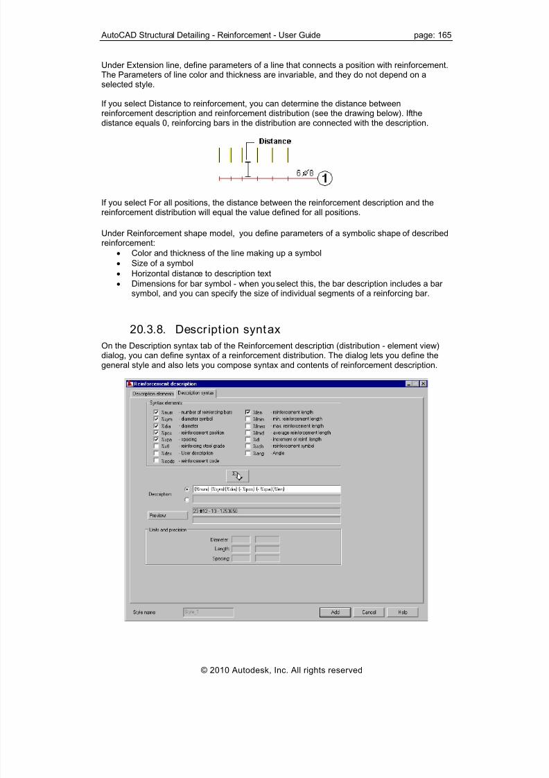
8/20/2019 Autocad Reinforcement Manual Eng
http://slidepdf.com/reader/full/autocad-reinforcement-manual-eng 172/222
AutoCAD Structural Detailing - Reinforcement - User Guide page: 165
Under Extension line, define parameters of a line that connects a position with reinforcement.
you select Distance to reinforcement, you can determine the distance betweenthe
The Parameters of line color and thickness are invariable, and they do not depend on aselected style.
If reinforcement description and reinforcement distribution (see the drawing below). If
distance equals 0, reinforcing bars in the distribution are connected with the description.
you select For all positions, the distance between the reinforcement description and the
nder Reinforcement shape model, you define parameters of a symbolic shape of described
nd thickness of the line making up a symbol
e to description text
select this, the bar description includes a bar
n (distribution - element view)
If reinforcement distribution will equal the value defined for all positions.
Ureinforcement:
• Color a
• Size of a symbol
• Horizontal distanc
• Dimensions for bar symbol - when yousymbol, and you can specify the size of individual segments of a reinforcing bar.
20.3.8. Descript ion syntax
On the Description syntax tab of the Reinforcement descriptiodialog, you can define syntax of a reinforcement distribution. The dialog lets you define thegeneral style and also lets you compose syntax and contents of reinforcement description.
© 2010 Autodesk, Inc. All rights reserved

8/20/2019 Autocad Reinforcement Manual Eng
http://slidepdf.com/reader/full/autocad-reinforcement-manual-eng 173/222

8/20/2019 Autocad Reinforcement Manual Eng
http://slidepdf.com/reader/full/autocad-reinforcement-manual-eng 174/222
AutoCAD Structural Detailing - Reinforcement - User Guide page: 167
The Reinforcement description dialog displays after you select the description of reinforcementdistribution (element view or element projection) and click New or Modify on the Description ofreinforcement shape dialog.
To add a new description of bar symbol, click Add after you define parameters of a bar symboldescription.
20.3.10. Descript ion elements
On the Description elements tab of the Reinforcement description (bar symbol/with variable L)dialog, you can define parameters such as colors, line thickness, font size, and label shape fora description.
The options included in the Position field refer to a label and the number that the labelcontains (see the drawing below).
Specify label parameters:
• Color
• Line thickness
• Shape
• Size
Specify label number parameters:
• Font style
• Color
• Size
© 2010 Autodesk, Inc. All rights reserved

8/20/2019 Autocad Reinforcement Manual Eng
http://slidepdf.com/reader/full/autocad-reinforcement-manual-eng 175/222
page: 168 AutoCAD Structural Detailing - Reinforcement - User Guide
Using the options under Description of leg length, you can define a description of the bar leglength:
• Style
• Color
• Size
• Position of the text with respect to the reinforcement
The options under Description text appearance define a description placed directly behind aposition:
• Style
• Color
• Size
• Position with respect to a label (horizontal distance)
20.3.11. Description syntax
On the Description syntax tab of the Reinforcement description (bar symbol/with variable L)dialog, you can define description syntax for a symbol of reinforcement whose description is
provided outside the formwork contour.
Under Syntax elements, select components and move them to the Description field (by
clicking the arrow under the element list), where you can arrange variables with user-definedtext and symbols. An example description is: f10 every 15 cm length = 2.0 m.
The Preview field displays a description of a reinforcement symbol that results from thedefined syntax. This description is based on number values that have been saved as fixed,and updates with changes in preferences (change of unit or precision). NOTE: units are notdisplayed in a preview.
Under Units and precision, the software displays the diameter, length, and spacing dataapplied while displaying a given value.
Variables included in a reinforcement symbol description:%num - number of reinforcing bars
%sym - diameter symbol%dia - diameter
© 2010 Autodesk, Inc. All rights reserved

8/20/2019 Autocad Reinforcement Manual Eng
http://slidepdf.com/reader/full/autocad-reinforcement-manual-eng 176/222
AutoCAD Structural Detailing - Reinforcement - User Guide page: 169
%pos - number of reinforcement position%spa - spacing%stl - reinforcement class%len - reinforcement length%lmin - minimum reinforcement length%lmax - maximum reinforcement length
%lmid - average reinforcement length%dl - increment of reinforcement length equal to a constant value%sch - reinforcement symbol%des - user description
Select User description in order to add text to the reinforcement description determined in theReinforcement description dialog (for longitudinal and transversal reinforcement, pointreinforcement, or distribution of reinforcement).
NOTE:The manner of reinforcement symbol description depends on the type of reinforcement beingdescribed and on the country code being applied.
Characters added should be put in brackets to ensure that, if any description data (such asspacing) is missing, the entire description text with a variable will not be displayed
NOTE:For example, if a bar symbol is to be included in the description of a defined reinforcing bar,select Reinforcement symbol and click the arrow. The variable containing a bar symbol will beadded to the Description edit field, and you should then click Add.
20.4. Wire fabrics
20.4.1. Wire fabric shape
The Reinforcement description dialog for wire fabric shape consists of 2 tabs:
• Description elements
• Description syntax
The Reinforcement description dialog displays after you select a description of the wire fabricshape and click New or Modify on the Description of reinforcement shape dialog.
To add a new description of the wire fabric shape, click Add button after you defineparameters of the wire fabric shape description.
20.4.2. Descript ion elementsOn the Description elements tab of the Reinforcement description (wire fabric shape) dialog,you can define parameters such as colors, line thickness, font size, and label shape for adescription.
© 2010 Autodesk, Inc. All rights reserved

8/20/2019 Autocad Reinforcement Manual Eng
http://slidepdf.com/reader/full/autocad-reinforcement-manual-eng 177/222
page: 170 AutoCAD Structural Detailing - Reinforcement - User Guide
The options included in the Position field refer to a label and the number that the labelcontains (see the drawing below).
Under Position, specify Label parameters:
• Colors for active and not active positions• Line thickness
• Label shape
• Label size
Specify Position Number parameters:
• Default position on a leader
• Color of active and not active positions
• Font style
• Font size
The active position referred to here is specified on the Reinforcement description dialog (see
the drawing below). If Active is selected for a given position, you choose a color from the Active list. If Active is not selected, you choose a color for this position from the Not active list.
The options under Description text appearance define a description placed between a position(label) and the described wire fabric:
• Style
• Color
• Size
• Position with respect to the auxiliary line (above only or above and below), and verticaltranslation with respect to the line.
© 2010 Autodesk, Inc. All rights reserved

8/20/2019 Autocad Reinforcement Manual Eng
http://slidepdf.com/reader/full/autocad-reinforcement-manual-eng 178/222
AutoCAD Structural Detailing - Reinforcement - User Guide page: 171
Under Auxiliary line, define parameters of a line that connects a position with reinforcement:
• Color
• Thickness
• Type of arrowheads
• Arrow size
Under Wire fabric shape, define parameters for a symbolic shape of the described wire fabric:Color and thickness of a line forming a symbolSize of a symbol sizeHorizontal distance to description textDimensions for wire fabric symbol - when you select this, the wire fabric description includes awire fabric symbol, and you can specify the size of individual segments of a wire fabric bar.
20.4.3. Descrption syntax
On the Description syntax tab of the Reinforcement description (wire fabric shape) dialog, youcan define syntax of a description of a wire fabric shape.
Under Syntax elements, select components and move them to the Description field (by
clicking the arrow under the element list), where you can arrange variables with user-definedtext and symbols.The Preview field displays a description of the wire fabric shape that results from the definedsyntax. This description is based on number values that have been saved as fixed, andupdates with changes in preferences (change of unit or precision). NOTE: units are notdisplayed in a preview.
Under Units and the precision, the software displays the diameter, length, and spacing dataapplied while displaying a given value.Variables included in a wire fabric description:
%num - number of wire fabrics%sym - wire fabric symbol%L1 - wire fabric length
%L2 - wire fabric width%des - user description%pos - reinforcement position
© 2010 Autodesk, Inc. All rights reserved

8/20/2019 Autocad Reinforcement Manual Eng
http://slidepdf.com/reader/full/autocad-reinforcement-manual-eng 179/222
page: 172 AutoCAD Structural Detailing - Reinforcement - User Guide
%sch - reinforcement symbol%lap_R - wire fabric lap (longitudinal)%lap_r - wire fabric lap (transversal)%stl - reinforcing steel grade
NOTE:The method of wire fabric description depends on the type of reinforcement being describedand on the country code being applied.
Any variables applied in a syntax must be put in brackets {}; you can add any text in betweenthe successive variables put in these brackets.
NOTE:For example, if a wire fabric symbol is to be included in the description of a defined wire fabric,select Reinforcement symbol and click the arrow. The variable containing a wire fabric symbolwill be added to the Description edit field, and you should then click Add.
20.4.4. Wire fabric distributionThe Reinforcement description dialog for wire fabric distribution consists of 2 tabs:
• Description elements
• Description syntax.
The Reinforcement description dialog displays after you select the description of wire fabricdistribution and click New or Modify on the Description of reinforcement shape dialog.
To add a new description of a wire fabric shape, click Add after you define parameters of awire fabric distribution description.
20.4.5. Descript ion elementsOn the Description elements tab of the Reinforcement description (wire fabric distribution)dialog, you can define parameters such as colors, line thickness, font size, and label shape fora description.
There are the following ways to display a wire fabric in drawings:
© 2010 Autodesk, Inc. All rights reserved

8/20/2019 Autocad Reinforcement Manual Eng
http://slidepdf.com/reader/full/autocad-reinforcement-manual-eng 180/222

8/20/2019 Autocad Reinforcement Manual Eng
http://slidepdf.com/reader/full/autocad-reinforcement-manual-eng 181/222
page: 174 AutoCAD Structural Detailing - Reinforcement - User Guide
20.4.6. Descript ion syntax
On the Description syntax tab of the Reinforcement description (wire fabric distribution) dialog,you can define the description syntax of wire fabric distribution.
Under Syntax elements, select components and move them to the Description field (bylicking the arrow under the element list), where you can arrange variables with user-defined
ription is based on number values that have been saved as fixed,nd updates with changes in preferences (change of unit or precision). NOTE: units are not
nder Units and precision, the software displays the diameter, length, and spacing data
Variable d in a w rics
l
R nal)%lap_r - wire fabric lap (transversal)%stl - reinforcing steel grade
c
text and symbols.
The Preview field displays a description of reinforcement distribution that results from adefined syntax. This descadisplayed in a preview.
Uapplied while displaying a given value.
s include ire fabrics description:%num - number of wire fab%sym - wire fabric symbo
%L1 - wire fabric length%L2 - wire fabric width%pos - reinforcement position%sch - reinforcement symbol%lap_ - wire fabric lap (longitudi
NOTE:The manner of reinforcement description depends on the type of reinforcement being
ny variables applied in a syntax must be put in brackets {}; you can add any text in betweenthe successive variables put in these brackets.
described and on the country code being applied.
A
© 2010 Autodesk, Inc. All rights reserved

8/20/2019 Autocad Reinforcement Manual Eng
http://slidepdf.com/reader/full/autocad-reinforcement-manual-eng 182/222
AutoCAD Structural Detailing - Reinforcement - User Guide page: 175
NOTE:For example, if a wire fabric symbol is to be included in the description of a defined wire fabric,elect Reinforcement symbol and click the arrow. The variable containing the wire fabric
you should then click Add.
alog for a wire fabric symbol consists of 2 tabs:
he Reinforcement description dialog displays after you select the description of the wire
add a new description of the wire fabric symbol, click Add after you define parameters of
iption elements tab of the Reinforcement description (wire fabric symbol) dialog,ou can define parameters such as colors, line thickness, font size, and label shape for a
description.
ssymbol will be added to the Description edit field, and
20.4.7. Wire fabric symbol
The Reinforcement description
• Description elements
di
• Description syntax
Tfabric symbol and click New or Modify on the Description of reinforcement shape dialog.
Tothe wire fabric symbol description.
20.4.8. Descript ion elementsOn the Descr y
he options included in the Position field refer to a label and the number that the labelns (see the drawing below).
Tcontai
© 2010 Autodesk, Inc. All rights reserved

8/20/2019 Autocad Reinforcement Manual Eng
http://slidepdf.com/reader/full/autocad-reinforcement-manual-eng 183/222
page: 176 AutoCAD Structural Detailing - Reinforcement - User Guide
Under Position, specify label parameters:
• Color
• Line thickness
• Label shape
• Label size
Specify position number parameters:• Font style
• Font color
• Font size
Define parameters for Description of leg length:
• Style
• Color
• Size
• Position of a text with respect to the described wire fabric
The options under Description text appearance define a description placed directly behind a
position:• Style
• Color
• Size
• Position with respect to a label (horizontal distance)
20.4.9. Descript ion syntax
On the Description syntax tab of the Reinforcement description (wire fabric symbol) dialog,you can define a description syntax for a wire fabric symbol.
Under Syntax elements, select components and move them to the Description field (byclicking the arrow under the element list), where you can arrange variables with user-definedtext and symbols.The Preview field displays a description of the wire fabric symbol that results from the definedsyntax. This description is based on number values that have been saved as fixed, andupdates with changes in preferences (change of unit or precision). NOTE: units are notdisplayed in a preview.
© 2010 Autodesk, Inc. All rights reserved

8/20/2019 Autocad Reinforcement Manual Eng
http://slidepdf.com/reader/full/autocad-reinforcement-manual-eng 184/222
AutoCAD Structural Detailing - Reinforcement - User Guide page: 177
Under Units and the precision, the software displays the diameter, length, and spacing dataapplied while displaying a given value.Variables included in the wire fabric description:
%num - number of wire fabrics%sym - wire fabric symbol%L1 - wire fabric length
%L2 - wire fabric width%des - user description%pos - reinforcement position%sch - reinforcement symbol%lap_R - wire fabric lap (longitudinal)%lap_r - wire fabric lap (transversal)%stl - reinforcing steel grade
NOTE:The method of wire fabric description depends on the type of reinforcement being describedand on the country code being applied.
Any variables applied in a syntax must be put in brackets {}; you can add any text in betweenthe successive variables put in these brackets.
20.5. Steel profiles
20.5.1. Steel prof ile
The Reinforcement description dialog for describing steel profiles consists of 2 tabs:
• Description elements
• Description syntax
The Reinforcement description dialog displays after you select a steel profile description andclick New or Modify on the Description of reinforcement shape dialog.
To add a new description of a steel profile, click Add button after you define parameters of thesteel profile description.
20.5.2. Descript ion elements
On the Description elements tab of the Reinforcement description (steel profiles) dialog, youcan define parameters such as colors, line thickness, font size, and label shape for adescription.
© 2010 Autodesk, Inc. All rights reserved

8/20/2019 Autocad Reinforcement Manual Eng
http://slidepdf.com/reader/full/autocad-reinforcement-manual-eng 185/222
page: 178 AutoCAD Structural Detailing - Reinforcement - User Guide
The options in the Position field refer to a label and the number that the label contains (see thedrawing below).
Under Position, specify label parameters:
• Colors for active and not active positions
• Line thickness
• Label shape
• Label size
Specify position number parameters:
• Default position on the extension line
• Colors for active and not active positions
• Font style
• Font size
The active position referred to here is specified on the Reinforcement description dialog (seethe drawing below). If Active is selected, you choose a color from the Active list. If Active is notselected, you choose a color from the Not active list.
The options under Description text appearance define a description placed between a position(label) and the described steel profile:
• Style
• Color
• Size
• Position with respect to the auxiliary line (above only or above and below)
© 2010 Autodesk, Inc. All rights reserved

8/20/2019 Autocad Reinforcement Manual Eng
http://slidepdf.com/reader/full/autocad-reinforcement-manual-eng 186/222
AutoCAD Structural Detailing - Reinforcement - User Guide page: 179
Under Auxiliary line, define parameters of a line connecting a position with the steel profile:
• Color
• Thickness
• Type of arrowheads
• Arrow size
20.5.3. Descript ion syntax
On the Description syntax tab of the Reinforcement description (steel profiles) dialog, you candefine a syntax of a steel profile description.
Under Syntax elements, select components and move them to the Description fields (byclicking the arrow under the element list), where you can arrange variables with user-definedtext and symbols.
The Preview field displays a steel profile description that results from the defined syntax. Thisdescription is based on numerical values that have been saved as fixed, and updates withchanges in preferences (change of unit or precision). NOTE: units are not displayed in apreview.
Under Units and precision, the software displays the diameter, length, and spacing dataapplied while displaying a given value.
Variables included in a steel profile description:%type – profile type
%len - reinforcement (profile) length
%pos - reinforcement position
%stl - reinforcing steel grade
%des - user description
NOTE:The manner of reinforcement description depends on the type of reinforcement beingdescribed and on the country code being applied.
Any variables applied in a syntax must be put in brackets {}; you can add any text between thesuccessive variables put in these brackets.
© 2010 Autodesk, Inc. All rights reserved

8/20/2019 Autocad Reinforcement Manual Eng
http://slidepdf.com/reader/full/autocad-reinforcement-manual-eng 187/222
page: 180 AutoCAD Structural Detailing - Reinforcement - User Guide
21. STYLES OF SYMBOLS
21.1. Styles of symbols
Use this option to define/modify symbols of axes, levels and sections used in elements of anRC structure. There are two ways to access this option from:
• Menu: Reinforcement / Graphic elements / Styles - graphic elements
• Ribbon: ASD - Reinforcement / Settings / Styles - graphic elements
• Command line: RBCT_DEF_SYMBOL_STYLE.
After selecting this option, the following dialog displays:
The following types of symbols are used for elements of RC structures (presented in theSymbol field in the dialog):
• Axis symbol
• Elevation mark symbol
• Section symbol.
For every symbol type a standard style is defined. After highlighting a symbol type and asymbol style, the current view of the symbol of an axis, level or section is presented in thecentral part of the dialog (in the Preview field).The right side of the dialog displays the following buttons (apart from the standard buttons OK, Cancel and Help):
• Default - clicking this button sets a selected style as a default symbol style for an axis,
level or section.• New - clicking this button opens one of the dialog: Axis, Elevation mark or Section
symbol, where a new style of the selected symbol type are defined (based on the existingstyle).
• Modify - clciking this button opens one of the following dialogs: Axis, Elevation mark orSection symbol, where a selected symbol type can be modified.
• Delete - clicking this button deletes a highlighted style from the list of styles available inthe Symbol styles field.
© 2010 Autodesk, Inc. All rights reserved

8/20/2019 Autocad Reinforcement Manual Eng
http://slidepdf.com/reader/full/autocad-reinforcement-manual-eng 188/222
AutoCAD Structural Detailing - Reinforcement - User Guide page: 181
21.2. Axis
Use this dialog to define a new style or to modify an existing style of an axis. After choosing anaxis style in the Symbol field, and clicking New or Modify from the Styles of symbols dialog,the following dialog displays:
The Axis field holds parameters of a line presenting the axis in a drawing: line type, color andthickness.In the Label field you determine parameters of a label of the axis description: label shape,size, color and thickness of the label line; the following label shapes are available: circle,ellipse, square, octagon. At the bottom of this field there are options that allow switching on /off the display of a label at ends of the axis.The options in the Text field refer to the axis description provided in the label. The followingparameters are defined: font style, color and size; additionally, it is possible to choose astructure axis prefix and a numbering type: with letters: A, B, C, with numerals: 1, 2, 3, withnumerals: I, II, III or by determining any other designations (after selecting the Define option).
To add a new axis description, specify a name of the axis description style (in the Style name
field) and click Add.
21.3. Elevation mark
Use this option to define a new style or to modify an existing style of an elevation mark. Afterchoosing an elevation mark style in the Symbol field, and clicking New or Modify in the Stylesof symbols dialog, the following dialog displays:
© 2010 Autodesk, Inc. All rights reserved

8/20/2019 Autocad Reinforcement Manual Eng
http://slidepdf.com/reader/full/autocad-reinforcement-manual-eng 189/222
page: 182 AutoCAD Structural Detailing - Reinforcement - User Guide
The Graphic symbol field holds parameters of a symbol representing a level in the drawing:symbol type, color, size and thickness of the line in the symbol.There are two options:
• Auxiliary line - if this option is selected, then the elevation mark symbol and the drawingwill present an auxiliary line connecting the elevation mark symbol with the level of an RCelement; when the option is cleared, the elevation mark symbol displays without anyadditional lines.
• ‘+’ for a positive value - if this option is selected, then the ‘+’ symbol appear when a valueof a number presented in the elevation mark symbol is greater than zero; if this option iscleared, a positive value is presented in the elevation mark symbol without any additionalsymbol.
The options in the Text field refer to the elevation mark description provided in the elevationmark symbol. Settings of the following parameters are defined: font style, color and size;additionally, it is possible to select a unit used to present a level value and number precision (anumber of decimal places).
To add a new elevation mark description, specify a name of the elevation mark descriptionstyle (in the Style name field) and click Add.
21.4. Section symbol
Use this dialog to define a new style or to modify an existing style of a section of an RCstructure element. After choosing a section symbol style in the Symbol field, click New or
Modify in the Styles of symbols dialog.The dialog consists of two tabs:Graphic designationSection description.
To add a new description of a section symbol, specify a name of the description style of thesection symbol (in the Style name field) and click Add.
© 2010 Autodesk, Inc. All rights reserved

8/20/2019 Autocad Reinforcement Manual Eng
http://slidepdf.com/reader/full/autocad-reinforcement-manual-eng 190/222
AutoCAD Structural Detailing - Reinforcement - User Guide page: 183
21.5. Graphic designation
After selecting the Graphic designation tab from the Section symbol dialog, the followingdialog displays:
The Position field holds parameters of a symbol representing the section of an RC structureelement in a drawing: graphic symbol type, arrowhead of the section symbol, symbol color,
size and thickness of a line in the symbol; besides, it is possible to select numbering of thesection symbol: with letters: A, B, C, with numerals: 1, 2, 3, with numerals: I, II, III or bydetermining any other designations (after the Define option is selected). An example of asection designation is displayed below.
The options provided in the Number field refer to a section description. The followingparameters can be set: font style, color and size.
© 2010 Autodesk, Inc. All rights reserved

8/20/2019 Autocad Reinforcement Manual Eng
http://slidepdf.com/reader/full/autocad-reinforcement-manual-eng 191/222
page: 184 AutoCAD Structural Detailing - Reinforcement - User Guide
21.6. Section description
After selecting the Section description tab from the Section symbol dialog, the following dialogdisplays:
The options located in the Description text field specify the description of an RC elementsection. The following parameters can be set: font style, color and size. Below are two options:
• Underline - if this option is selected, then the section description (name) will beadditionally underlined with a line of a selected color and thickness; if this option iscleared, the section name will not be underlined
• Prefix - if this option is selected, then an additional edit field is accessible in which it ispossible to define any character string being a prefix of the section name.
An example of a designation of the section name is displayed below.
© 2010 Autodesk, Inc. All rights reserved

8/20/2019 Autocad Reinforcement Manual Eng
http://slidepdf.com/reader/full/autocad-reinforcement-manual-eng 192/222
AutoCAD Structural Detailing - Reinforcement - User Guide page: 185
22. DRAWING TEMPLATE STYLES
22.1. Construction drawings - settings
The drawing templates manager allows to define how the structure drawings of elements in AutoCAD® Structural Detail ing - Rein forcement will be created. It includes definingparameters of appearance of individual structure elements (colors, scale, plans, reinforcementdescriptions, etc.); drawing templates for each type of element are created this way.
NOTE: All the parameters defined in the dialog refer to the link between the AutoCAD® StructuralDetailing - Reinforcement and Autodesk Revit Structure or Autodesk Robot Structural Analysis. The reinforcement drawings generated for the structure elements transferred to AutoCAD® Structural Detailing - Reinforcement from the applications mentioned above will becreated in accordance with the settings saved in the drawing templates manager.
The Drawing templates manager dialog can be open from:• Menu: Reinforcement / Structure elements - reinforcement / Construction drawing -settings
• Ribbon: ASD Reinforcement / Settings / Styles / Construction drawing - settings or ASDStructure elements / Settings / Styles / Construction drawing - settings
• Command line: STYLE_DG.
The structure drawings are parametrized by a set of styles. They are divided in groups whichparametrize the specified components of a structure drawing of an element.The following components of drawings are available: Adjoining elementsSection / View - parameters/Drawing layoutDimensioningReinforcement description.
Use the buttons on the right to work with drawing components:
• Default - click this to designate a template as a default drawing template for a selecteddrawing component
• New - click this to open a dialog where you can define a new template for drawingcomponents.
© 2010 Autodesk, Inc. All rights reserved
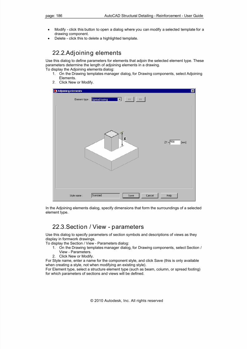
8/20/2019 Autocad Reinforcement Manual Eng
http://slidepdf.com/reader/full/autocad-reinforcement-manual-eng 193/222
page: 186 AutoCAD Structural Detailing - Reinforcement - User Guide
• Modify - click this button to open a dialog where you can modify a selected template for adrawing component.
• Delete - click this to delete a highlighted template.
22.2. Adjoining elementsUse this dialog to define parameters for elements that adjoin the selected element type. Theseparameters determine the length of adjoining elements in a drawing.To display the Adjoining elements dialog:
1. On the Drawing templates manager dialog, for Drawing components, select AdjoiningElements.
2. Click New or Modify.
In the Adjoining elements dialog, specify dimensions that form the surroundings of a selectedelement type.
22.3. Section / View - parameters
Use this dialog to specify parameters of section symbols and descriptions of views as theydisplay in formwork drawings.To display the Section / View - Parameters dialog:
1. On the Drawing templates manager dialog, for Drawing components, select Section /View - Parameters.
2. Click New or Modify.For Style name, enter a name for the component style, and click Save (this is only availablewhen creating a style, not when modifying an existing style).For Element type, select a structure element type (such as beam, column, or spread footing)for which parameters of sections and views will be defined.
© 2010 Autodesk, Inc. All rights reserved

8/20/2019 Autocad Reinforcement Manual Eng
http://slidepdf.com/reader/full/autocad-reinforcement-manual-eng 194/222
AutoCAD Structural Detailing - Reinforcement - User Guide page: 187
The dialog box consists of two tabs: Section and View.In the upper part of the dialog, it is possible to select style of the graphic presentation of thegraphic elements, according to which the edges of the elements will be drawn.
Options for the drawing of an element section are available on the Section tab:
• style - the list includes all the defined styles of section symbols. Click the Browse (...)button to open the Styles of symbols dialog, where you can select or modify an existingstyle of that symbol.
• symbol - it switches on / off the symbol presentation of a section in the structure drawings• distance - specifies a distance between the section symbol and the element contour
• structure axes - switches on / off the presentation of the structure axes and enablesselection of the style of their presentation
• elevation mark - switches on / off the presentation of the structure axes and enablesselection of the style of their presentation
Options for the parametrization of view of the drawing element are available on the View tab:
• description components - define the syntax of a section description. Because adescription may consist of 2 lines of text, there are 2 edit fields. Select a descriptioncomponent, click the arrow, and the selected description components are moved to theactive edit field. A preview of the resulting syntax displays below the edit fields.
%El_name - element name (position name)
%Quant - quantity (number of positions)%Scale - scale of the drawing of an element view
• description text - define the color, style, and size of description text.
• description location - select from several description positions, and specify a distancebetween the description and the view drawing.
• structure axes - switches on / off the presentation of the structure axes and enablesselection of the style of their presentation
• elevation mark - switches on / off the presentation of the structure axes and enablesselection of the style of their presentation
© 2010 Autodesk, Inc. All rights reserved

8/20/2019 Autocad Reinforcement Manual Eng
http://slidepdf.com/reader/full/autocad-reinforcement-manual-eng 195/222
page: 188 AutoCAD Structural Detailing - Reinforcement - User Guide
22.4. Drawing layout
Using this dialog, you can specify which drawings will be generated (and in what scale) forselected types of structure elements.To display the Drawing layout dialog:
1. On the Drawing templates manager dialog, for Drawing components, select Drawinglayout.
2. Click New or Modify.For Style name, enter a name for the component style, and click Save (this is only availablewhen creating a style, not when modifying an existing style).
The dialog presents layout of views/plans to which the views or section elements can beassigned.Clicking an icon that symbolizes a generated drawing will display the additional dialog Drawingcomponents.If an empty icon displays for a selected drawing layout and a selected structure element type,the field does not contain a drawing.
22.5. DimensioningUsing this dialog, you can define the method of dimensioning structure elements on drawings.Parametrization of the dimensioning lines is separate for the defined element views (view,section).To display the Dimensioning layout dialog:
1. On the Drawing templates manager dialog, for Drawing components, selectDimensioning.
2. Click New or Modify.For Style name, enter a name for the component style, and click Save (this is only availablewhen creating a style, not when modifying an existing style).
© 2010 Autodesk, Inc. All rights reserved

8/20/2019 Autocad Reinforcement Manual Eng
http://slidepdf.com/reader/full/autocad-reinforcement-manual-eng 196/222
AutoCAD Structural Detailing - Reinforcement - User Guide page: 189
A selection list for selection of a structure element type (beam, column, spread footing, etc.) islocated in the upper part of the dialog; it defines for which element the dimensioningparameters will be defined.Design styles defined in AutoCAD® can be selected from the selection list. It is possible to set
distance between the design lines in the edit fields.On tabs related to the specified elements of view, it is possible to set location of the totaldimension and, optionally, dimensions of openings and the characteristic points of an element.
22.6. Reinforcement description
Using this dialog, you can define the method of reinforcement description in the structuredrawings of the elements. Parametrization of the reinforcement description is separate for thedefined element views (view, section).To display the Reinforcement description dialog:
1. On the Drawing templates manager dialog, for Drawing components, selectReinforcement description.
2. Click New or Modify.For Style name, enter a name for the component style, and click Save (this is only availablewhen creating a style, not when modifying an existing style).
© 2010 Autodesk, Inc. All rights reserved

8/20/2019 Autocad Reinforcement Manual Eng
http://slidepdf.com/reader/full/autocad-reinforcement-manual-eng 197/222
page: 190 AutoCAD Structural Detailing - Reinforcement - User Guide
A selection list for selection of a structure element type (beam, column, spread footing, etc.) islocated in the upper part of the dialog; it defines for which element the reinforcementdescription will be defined.The options parametrizing the description location and the description styles are available ontabs related to the specified element views.The settings related to the description location include separate parameters for the distributionof bars and for single bars. It is possible to define distances between the descriptions andelement edges (in the units used in the model). It is possible to define location of the bardistribution description and the leader type for single bars in the selection fields.Settings related to the description styles include separate parameters for different types of thepresented reinforcement. It is possible to select the description types, the method of
presentation of the distribution bars and the description style for the bar distribution. Thedescription style defined in the program settings can be defined for bars and steel profiles.Parameters related to generation of the reinforcement table and the symbols of bars in thecreated drawings of elements are available in the bottom part of the dialog. It is possible toselect the reinforcement table type and its style in accordance with the settings defined in the AutoCAD® Structural Detailing - Reinforcement DWT file.If you select drawing symbols of bars in accordance with a specified style, the symbols of barsare added to the reinforcement drawings (views and sections of the structure element).
© 2010 Autodesk, Inc. All rights reserved

8/20/2019 Autocad Reinforcement Manual Eng
http://slidepdf.com/reader/full/autocad-reinforcement-manual-eng 198/222
AutoCAD Structural Detailing - Reinforcement - User Guide page: 191
23. REINFORCEMENT TABLES
23.1. Reinforcement tables (style manager)
Use this option to define/modify tables used to prepare the tables of reinforcement in RCstructure elements. There are two ways to access this option from:
• Menu: Reinforcement / Reinforcement tables / Styles - reinforcement tables
• Ribbon: ASD - Reinforcement / Settings / Styles - reinforcement tables
• Command line: RBCR_LIST_PAR.
NOTE:Reinforcement tables in AutoCAD® Structural Detail ing - Reinforcement are updatedautomatically after modifying a drawing, if in the Options dialog (the Structural Detailing tab)the Automatic table update option is selected.
After selecting the option, the Reinforcement tables - style manager dialog displays:
The following types of the reinforcement table are available in the Table field:
• MAIN - reinforcing bars
• SUMMARY - reinforcing bars
• DETAILED - reinforcing bars
• MAIN - elements (see Element manager)
• MAIN - wire fabrics
• SUMMARY - wire fabrics
• MAIN - (steel) profiles.The individual types of reinforcement tables present the following information:
• MAIN table – it is a global reinforcement table
• SUMMARY table – it is a reinforcement table intended only for the distribution varyinglinearly (e.g. for stirrups distributed within a tapered beam), to obtain such a table,choose reinforcement distribution varying linearly and select the option Reinforcementtable / Summary table
• DETAILED table – it is a summary table concerning the reinforcement steel consumptionbroken down by bar diameters (see also: Generation of distribution varying linearly anddetailed table) – available for distribution varying linearly and bar surface distribution.
For each table type, the standard table style (it is presented in the Table style field) is defined.Once the table type and table style are highlighted, the view of a selected table style ispresented in the middle part of the dialog (the Preview field).The right side of the dialog (apart from the standard buttons OK, Cancel and Help) containsthe following buttons:
• Default - click this button to select a style for the default table layout (description style)
© 2010 Autodesk, Inc. All rights reserved

8/20/2019 Autocad Reinforcement Manual Eng
http://slidepdf.com/reader/full/autocad-reinforcement-manual-eng 199/222
page: 192 AutoCAD Structural Detailing - Reinforcement - User Guide
• New - click this button to open the Definition of new reinforcement table style dialogwhere a new style of a selected table type can be defined (based on the style thatalready exists)
• Modify - click this button to open the Modification of reinforcement table style dialogwhere changes can be made in a selected table type and table style
• Delete - click this button to delete the highlighted table style from the list of styles
available in the Table style field.
23.2. Style definit ion/modification
23.2.1. Definition/modification of reinforcement tablestyle
Use this dialog to define a new style or to modify an existing style of a table type.
The Definition of new reinforcement table style dialog is opened by clicking New in theReinforcement tables (style manager) dialog (the Modification of reinforcement table style
dialog can be opened by clicking Modify).
The dialog box consists of three tabs:Table: layout and componentsFont, color, lineOptions.
NOTE:If one of the reinforcement table types for bars is chosen (MAIN - bars, MAIN - elements,SUMMARY - bars, DETAILED - bars, MAIN - profiles), there is also another tab available:Sorting and detailed options.
NOTE:If the type SUMMARY – wire fabrics is chosen, then another tab Display options (wire fabriccuts) is also available for wire fabrics.
23.2.2. Table layout and components
The following dialog displays, after selecting the Table: layout and components tab from theDefinition/modification of reinforcement table style dialog.
© 2010 Autodesk, Inc. All rights reserved

8/20/2019 Autocad Reinforcement Manual Eng
http://slidepdf.com/reader/full/autocad-reinforcement-manual-eng 200/222
AutoCAD Structural Detailing - Reinforcement - User Guide page: 193
NOTE:The options located on this tab depend on a table type selected in the Reinforcement tables- sty le manager dialog. The drawing above shows the options available after selecting themain table for reinforcing bars.
The bottom part of the dialog contains the Style name edit field; a name of the defined tablestyle should be entered there (in case of modifying the table style, the Style name field isinaccessible).To define/modify a table style:
• Select a set of table components (e.g. in the above dialog: Main, Quantities, Lengths,Sums)
• In the next field, select the components to be included in the table (the option is selected
when √ symbol appears)
• Click >>.
The right side of the dialog is used to define the table layout.
For example, for a bar symbol (shape) to be presented in the MAIN reinforcement table:
1. In the Reinforcement tables – style manager dialog, select the MAIN table2. Click Modify.3. On the Table: layout and components tab in the Modification of reinforcement table style
dialog select the Bar symbol option4. Click >>, to add a new column to the main reinforcement table5. Set the added column with the bar symbol in the appropriate place in the table6. Click OK.
Use the same method to add the remaining components to the reinforcement table.
NOTE:Column positions and column names can be modified for each reinforcement table style.
The following options are also available in the above dialog:• Total table width - inaccessible edit field displays the defined table width.
• Buttons: Zoom in, Zoom out, 100% - allow zooming in/zooming out.
• Fit button – adjusts (fits) the width of table columns to the length of texts in columnheadings.
The order of individual table columns can be arranged by left-clicking the entire column, andmoving the column to the selected position. In a table, the cell height can be increased and inthe table heading, the descriptions or changed names of the existing columns can be entered.
The tables enable you to:
• Add blank lines at the beginning and end of a table
• Add blank columns in tables
• Define exact table dimensions (column width and line height) – dimensions of the columnwidth and the line height are presented under the table and to the left of the table,respectively.
© 2010 Autodesk, Inc. All rights reserved
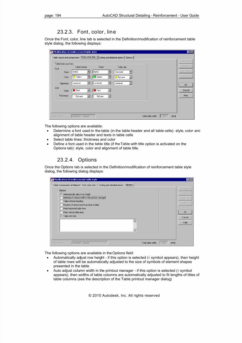
8/20/2019 Autocad Reinforcement Manual Eng
http://slidepdf.com/reader/full/autocad-reinforcement-manual-eng 201/222
page: 194 AutoCAD Structural Detailing - Reinforcement - User Guide
23.2.3. Font, color , line
Once the Font, color, line tab is selected in the Definition/modification of reinforcement tablestyle dialog, the following displays:
The following options are available:
• Determine a font used in the table (in the table header and all table cells): style, color andalignment of table header and texts in table cells
• Select table lines: thickness and color
• Define a font used in the table title (if the Table with title option is activated on theOptions tab): style, color and alignment of table title.
23.2.4. Options
Once the Options tab is selected in the Definition/modification of reinforcement table styledialog, the following dialog displays:
The following options are available in the Options field:
• Automatically adjust row height - if this option is selected (√ symbol appears), then heightof table rows will be automatically adjusted to the size of symbols of element shapespresented in the table
• Auto adjust column width in the printout manager - if this option is selected (√ symbol
appears), then widths of table columns are automatically adjusted to fit lengths of titles oftable columns (see the description of the Table printout manager dialog)
© 2010 Autodesk, Inc. All rights reserved

8/20/2019 Autocad Reinforcement Manual Eng
http://slidepdf.com/reader/full/autocad-reinforcement-manual-eng 202/222
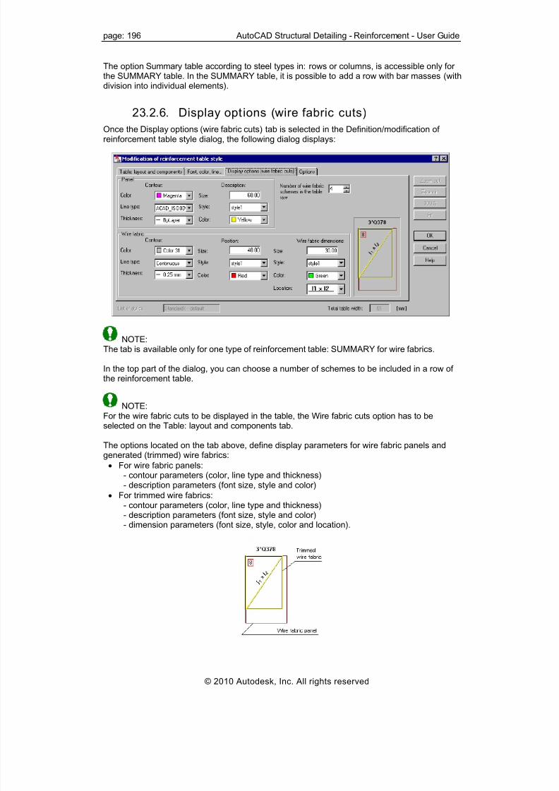
8/20/2019 Autocad Reinforcement Manual Eng
http://slidepdf.com/reader/full/autocad-reinforcement-manual-eng 203/222
page: 196 AutoCAD Structural Detailing - Reinforcement - User Guide
The option Summary table according to steel types in: rows or columns, is accessible only forthe SUMMARY table. In the SUMMARY table, it is possible to add a row with bar masses (withdivision into individual elements).
23.2.6. Display opt ions (wire fabric cuts)
Once the Display options (wire fabric cuts) tab is selected in the Definition/modification ofreinforcement table style dialog, the following dialog displays:
NOTE:The tab is available only for one type of reinforcement table: SUMMARY for wire fabrics.
In the top part of the dialog, you can choose a number of schemes to be included in a row of
the reinforcement table.
NOTE:For the wire fabric cuts to be displayed in the table, the Wire fabric cuts option has to beselected on the Table: layout and components tab.
The options located on the tab above, define display parameters for wire fabric panels andgenerated (trimmed) wire fabrics:
• For wire fabric panels:- contour parameters (color, line type and thickness)- description parameters (font size, style and color)
• For trimmed wire fabrics:
- contour parameters (color, line type and thickness)- description parameters (font size, style and color)- dimension parameters (font size, style, color and location).
© 2010 Autodesk, Inc. All rights reserved

8/20/2019 Autocad Reinforcement Manual Eng
http://slidepdf.com/reader/full/autocad-reinforcement-manual-eng 204/222
AutoCAD Structural Detailing - Reinforcement - User Guide page: 197
24. PRINTOUT
24.1. Table printout manager
Use this option to define/modify the printout layout for tables used to prepare steel summary
tables.
To begin defining a printout layout, open the Table printout manager dialog from:
• Menu: Steel / Tables / Table Printout Manager (steel part) or Reinforcement /Reinforcement table / Table Printout / Export / Edit (reinforcement part)
• Ribbon: ASD - Drawings / Tables / Table Printout Manager (steel part) or ASD -Reinforcement / Reinforcement table / Table Printout / Export / Edit (reinforcementpart)
• Toolbar: Table Printout Manager (steel part) or Table Printout / Export / Edit
(reinforcement part)
• Command line: RBCS_LISTPRINT (steel part) or RBCR_LIST_EXP (reinforcementpart).
NOTE:If you select Automatic table update on the Structural Detailing tab of the Options dialog,reinforcement tables in AutoCAD® Structural Detailing - Reinforcement will be updatedautomatically after changes are made in a drawing.
The Table printout manager dialog has 2 primary parts:
• On the left is the selection tree (see the drawing below) from which you can select one ofthe printout manager options
© 2010 Autodesk, Inc. All rights reserved

8/20/2019 Autocad Reinforcement Manual Eng
http://slidepdf.com/reader/full/autocad-reinforcement-manual-eng 205/222
page: 198 AutoCAD Structural Detailing - Reinforcement - User Guide
• To the right of the selection tree are the parameters that relate to the option youselected in the selection tree. The top part of the dialog shows the layout of a selectedtable type.
• Use the icons at the top of the dialog:
Printout preview - click this to open a preview of a table printout; return to thedialog by clicking Close
Print table - click this to start printing a table
Save table - click this to open the dialog in which a table may be saved in MSExcel®:o *.CSV (Comma Separated Values) format files which are text fileso *.XLS format files – this saving method fully reflects table settings that can be
seen in a preview window
Save table (MS Word) - click this to open the Save As dialog, where you cansave a table in an MS Word file with the specified name
Save graphical settings - click this to save current settings of the printout
manager
Automatic adjust of column width to header text - click this to adjust the width oftable columns to the length of table column names
Help - click this to open Help
NOTE:
For AutoCAD® Structural Detailing – Reinforcement, an additional icon lets you insert atable into an edited drawing.
Although a table shape (cell height, column width) depends directly on a defined table style,you can determine the shape.In addition, there is a context menu with the following options:
• Table cells – group (merges several table cells into one cell) or ungroup
• Text orientation – vertical, horizontal
• Adding or deleting a column in the table
• Adding or deleting a row in the table
The example below shows a table layout after adding a new column at the beginning of thetable, merging several table cells, and changing text orientation to vertical. The table displaysdata for a few positions of structure element reinforcement.
© 2010 Autodesk, Inc. All rights reserved

8/20/2019 Autocad Reinforcement Manual Eng
http://slidepdf.com/reader/full/autocad-reinforcement-manual-eng 206/222
AutoCAD Structural Detailing - Reinforcement - User Guide page: 199
24.2. Table composit ion
After you select Table composition from the selection tree in the left part of the Table printoutmanager dialog, the options shown below display on the right.
For steel structure elements, choose a table type:
• Material summary
• Plate summary• Profile summary
• User parts
• Element list
• Assembly list
• Bolt (rivet) list
• Cut list
• Bolt assign
For RC structure elements, choose a table type:
• Main (reinforcing bars)
• Summary (reinforcing bars)
• Detailed (reinforcing bars) - this requires graphically selecting the distribution varying
linearly / surface bar distribution or entering a number of reinforcement position• Main (elements) – see the description of the Element manager dialog
• Main (wire fabrics)
• Summary (wire fabrics)
For each table type, you can choose a table style defined previously for the selected tabletype.Click Create to generate a table of a given type based on the current element list (if the list isempty, a printout of a whole structure is made) in the format of the active table style (see:Styles applied in tables).
The List of elements field displays numbers of the elements included in a table. ClickingSelection closes the dialogs and lets you graphically select elements to be included in thetable.
© 2010 Autodesk, Inc. All rights reserved

8/20/2019 Autocad Reinforcement Manual Eng
http://slidepdf.com/reader/full/autocad-reinforcement-manual-eng 207/222
page: 200 AutoCAD Structural Detailing - Reinforcement - User Guide
Clicking Edit table lets you graphically indicate the table to be edited. Changes made in a tablemay be saved after you click Save changes.Use the options at the bottom of the dialog:
• Number of first page - specify a number of the first page to be printed
• Add header - if this is selected, a defined header will display on a printout
• Add footer - if this is selected, a defined footer will display on a printout.
24.3. Page setup
After you select Page setup from the selection tree in the left part of the Table printoutmanager dialog, the options shown below display on the right.
Determine the manner of table presentation:
• Under Titles and table lines:o Vertical lines – if this is not selected, no vertical lines are displayed in a tableo Horizontal lines – if this is not selected, no horizontal lines are displayed in a tableo Print black and white – if this is not selected, a table is printed with the defined
colors applied
• Under Center table on a page, specify how a table is to be centered (horizontally,
vertically, or both)• Under Orientation, define paper orientation (Portrait - the longer side of a paper sheet
is vertical or Landscape - the longer side of a paper sheet is horizontal)
24.4. Frames After you select Frames from the selection tree in the left part of the Table printout managerdialog, the options shown below display on the right.
Determine the manner of table framing:
• None - no separation between a header/footer and table
• Border lines – includes lines that separate header and footer from the table
• Frames for – select to include frames for the header, the table, the footer, or anycombination of the three
© 2010 Autodesk, Inc. All rights reserved

8/20/2019 Autocad Reinforcement Manual Eng
http://slidepdf.com/reader/full/autocad-reinforcement-manual-eng 208/222

8/20/2019 Autocad Reinforcement Manual Eng
http://slidepdf.com/reader/full/autocad-reinforcement-manual-eng 209/222
page: 202 AutoCAD Structural Detailing - Reinforcement - User Guide
24.7. Header
After you select Header from the selection tree in the left part of the Table printout managerdialog, the options shown below display on the right.
In order to change the layout of the printout header, select the table field you want to change,
and then select a value from the list. To select a font for a particular field, position the cursor inthe field, and click Font. In the dialog that opens, you can choose the font to be applied.
24.8. Footer
After you select Footer from the selection tree in the left part of the Table printout managerdialog, the options shown below display on the right.
In order to change the layout of the printout footer, select the table field you want to change,and then select a value from the list. To select a font for a particular field, position the cursor inthe field, and click Font. In the dialog that opens, you can choose the font to be applied.
24.9. Parameters
After you select Parameters from the selection tree in the left part of the Table printoutmanager dialog, the options shown below display on the right.
The dialog contains all the variables defined in the system and their names.
© 2010 Autodesk, Inc. All rights reserved

8/20/2019 Autocad Reinforcement Manual Eng
http://slidepdf.com/reader/full/autocad-reinforcement-manual-eng 210/222
AutoCAD Structural Detailing - Reinforcement - User Guide page: 203
NOTE:In order to confirm a variable and its modifications, click Set.
Variables used for formatting the header and footer of the printout:
VAR_PAGE_NUMBER - lets you assign a current printout page. If VAR_PAGE_TOTAL isused, text assigned to the variable will precede the total number of pages (for example, Page1, Page 2, and so on)VAR_PAGE_TOTAL - value of this variable indicates the total number of printout pages. Textassigned to it may be preceded by a current page number, if the VAR_PAGE_NUMBERvariable is used.VAR_DATE, VAR_TIME - these variables may be assigned any text and combination of thekey words displayed below (prints the current date/time on a printout):%A - full week day name (Monday)%a - abbreviated week day name (Mon)%B - full month name (January)%b - abbreviated month name (Jan)%c - standard presentation of date and time
%d - month day (01-31)%H - time (24-hour clock) (00-23)%I - time (12-hour clock) (01-12)%j - successive day of the year (001-366)%M - minute (00-59)%m - month (01-12)%p - local equivalent of the English abbreviations AM / PM%S - second (00-59)%U - successive week of the year (first day - Sunday) (00-53)%W - successive week of the year (first day - Monday) (00-53)%w - day of the week (0-6, Sunday is denoted by 0)%X - standard time representation%x - standard date representation
%Y - year and century%y - year without the century specified (00-99)%Z - time zone name%% - percent markStandard date representation is the following string of variables: %a %b %d %YStandard time representation is the following string of variables: %H:%M:%SStandard date and time representation is the following string of variables: %a %b %d%H:%M:%S %Y.
The remaining variables listed below do not contain other values than user-defined text. Theirnames serve only for the purpose of convenient classification while formatting.
The following printout variables may be used in AutoCAD® Structural Detailing -
Reinforcement:VAR_INV_NAME – investor nameVAR_INV_ADDRESS – investor addressVAR_INV_PHONE – investor phoneVAR_INV_FAX – investor faxVAR_INV_EMAIL – investor e-mail addressVAR_OFF_NAME – design office nameVAR_OFF_ADDRESS - design office addressVAR_OFF_PHONE - design office phoneVAR_OFF_FAX - design office faxVAR_OFF_EMAIL - design office e-mail addressVAR_SCALE – drawing scaleVAR_DRAW_NAME – drawing name
VAR_FILE – name of a DWG file including a drawingVAR_DESIGNER - designer
© 2010 Autodesk, Inc. All rights reserved

8/20/2019 Autocad Reinforcement Manual Eng
http://slidepdf.com/reader/full/autocad-reinforcement-manual-eng 211/222
page: 204 AutoCAD Structural Detailing - Reinforcement - User Guide
VAR_VERIF - verificationVAR_PROJ_NAME, VAR_PROJ_NUMVAR_REV_NAME, VAR_REV_NUMVAR_LOGO – access path to a BMP fileYou can also use these variables when creating your own printout layouts. When you insertsuch a layout, the software will automatically fill out variables with values specified in the table
printout manager.
24.10. Templates
After you select Templates from the selection tree located in the left part of the Table printoutmanager dialog, the options shown below display on the right.
You can select templates for printing tables to the following programs:
• MS Word®: DOT format files
• MS Excel®: XLT format files
In the edit fields, specify file names with a full access path. After you click Search, you canspecify a template file from the computer hard disk.
In AutoCAD® Structural Detailing - Reinforcement, there are additional options available forprintouts to MS Word®. They let you insert an additional summary table that includes
information about the reinforcement (if Attach summary table is selected). You can set thetable either at the end of the entire printout or for several successive reinforcements on apage. Additional options:
• Automatic column width - when this is selected, widths of table columns areautomatically adjusted to fit the length of names of table columns.
• Automatic row height - when this is selected, heights of table rows are automaticallyadjusted to contents of table rows.
24.11. Example of definition of views andgeneration of the final drawing
The following example illustrates the generation of drawings of a spread footing and an RCcolumn generated with the use of the macros available in AutoCAD® Structural Detail ing –Reinforcement . (Use the Model tab to define which views display in the illustration).
© 2010 Autodesk, Inc. All rights reserved
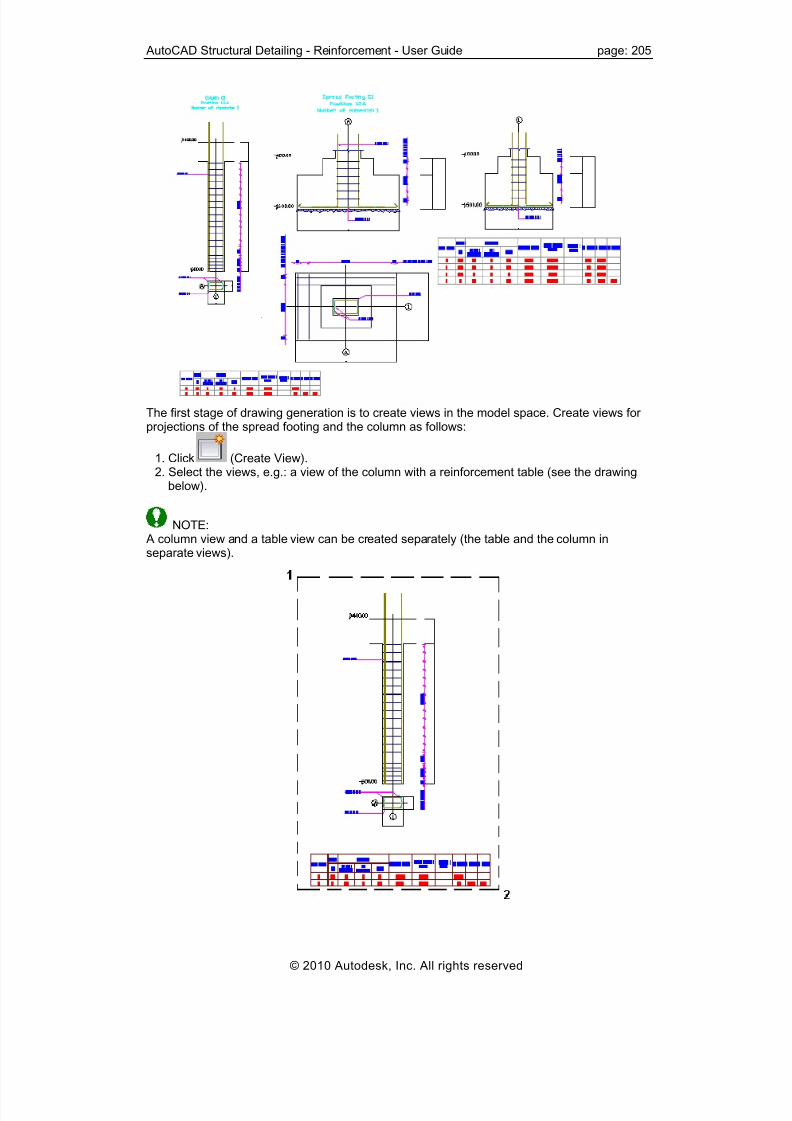
8/20/2019 Autocad Reinforcement Manual Eng
http://slidepdf.com/reader/full/autocad-reinforcement-manual-eng 212/222
AutoCAD Structural Detailing - Reinforcement - User Guide page: 205
The first stage of drawing generation is to create views in the model space. Create views forprojections of the spread footing and the column as follows:
1. Click (Create View).2. Select the views, e.g.: a view of the column with a reinforcement table (see the drawing
below).
NOTE:
A column view and a table view can be created separately (the table and the column inseparate views).
© 2010 Autodesk, Inc. All rights reserved

8/20/2019 Autocad Reinforcement Manual Eng
http://slidepdf.com/reader/full/autocad-reinforcement-manual-eng 213/222

8/20/2019 Autocad Reinforcement Manual Eng
http://slidepdf.com/reader/full/autocad-reinforcement-manual-eng 214/222
AutoCAD Structural Detailing - Reinforcement - User Guide page: 207
24.12. List of commands available in the printoutmodule
This module enables printouts. The following commands are available:
RBCT_ACTDOC Available for a selected document located in the option tree; activates a selected document(for its edition) in the edition layout. There may be many documents created, but only one isactive, i.e. may be edited.
RBCT_ADDTOPRINT Available for a selected view located in the position tree; composes a final printout. The layout,to which the view is to be added, must be active. The command adds a selected view to thecurrent layout (printout); NOTE: a view may be contained only on one printout.
RBCT_ADDALLTOPRINT Available for a selected document provided in the position tree; composes a final printout. The
layout, to which the view is to be added, must be active. The command adds all the viewsbelonging to a given document (not added to other printout, yet) to the current layout.
RBCT_FITVIEWS Available for an active document – provides greater work convenience to the user. The editionlayout must be active. The command results in adjusting dimensions of views included in theedition layout to the current size of the AutoCAD® program window.
RBCT_DELPRINTOUT Available for a selected printout in the printout tree; the command is used to delete a printout.The command also deletes the corresponding layout.
RBCT_REMFROMRINT
Available for a selected view provided in the printout tree; the command removes a view froma printout; the command removes the view only from a printout - it remains in a document andmay be reused (e.g. by adding it to other printout).
RBCT_DELALLFROMPRINT Available for a selected document located in the printout tree; the command removes viewsbelonging to a selected document from the printout. The views remain in a document and maybe reused (e.g. by adding them to other printout).
RBCT_DELDOC Available for a selected document located in the position tree; the command deletes adocument from the list of documents created for a given position.
RBCT_EDITVIEW Available for a selected view provided in the printout tree; the command switches to the editionmode for a selected view. The command enables you to switch from edition of a printout toedition of a view (drawing) included in it. The command activates the edition layout and adocument whose component is the selected view.
RBCT_EDITDOC Available for a selected document provided in the printout tree; the command used to switch tothe edition mode of a selected document. The command enables you to switch from edition ofa printout to edition of views (drawings) included in it. The command activates the editionlayout and the selected document.
RBCT_MEDIT_ON
Available for an active document containing one view; the command allows editing adocument in the model layout.
© 2010 Autodesk, Inc. All rights reserved

8/20/2019 Autocad Reinforcement Manual Eng
http://slidepdf.com/reader/full/autocad-reinforcement-manual-eng 215/222
page: 208 AutoCAD Structural Detailing - Reinforcement - User Guide
RBCT_MEDIT_OFFThe command restores the standard functionality of the model layout.
RBCT_REG_LAYER Available for the active document and view; after adding a layer, you can change its name by
means of the options available in the AutoCAD® program. The program manages layerswithin the available views and documents. A layer must be added using the AutoCAD®Structural Detailing options (the problem concerns only the layers used in the edition layout).
RBCT_DELETEPOS Available for a position selected in the position tree; the command is used to delete a position;NOTE: only positions that are defined may be deleted - positions created on the basis ofmodel elements cannot be deleted.
RBCT_RENAMEPOS Available for a position selected in the position tree; the command enables changing the nameof a position.
RBCT_RENAMEVIEW Available for a view selected in the position tree; the command enables changing the name ofa view.
RBCT_RENAMEDOC Available for a document selected in the position tree; the command enables changing thename of a document.
RBCT_RENAMEPRINTOUT Available for a printout selected in the printout tree; the command enables changing the nameof a printout; a printout name is always identical to the name of a layout (printout)corresponding to it.
RBCT_ACTVIEW Available for a view selected in the position tree; the command makes the view of the AutoCAD® program which corresponds to the selected view, become active; NOTE: a viewmust be a component of the active document.
RBCT_ADDTEMPLATEThe command results in adding a new template in the dialog; which opens once this option isselected. You can specify the name of a new template and choose one of the registeredtemplate types.
RBCT_DELTEMPLATE Available for a template selected in the template tree; the command deletes a selectedtemplate.
RBCT_RENAMETEMPLATE Available for a template selected in the template tree; the command allows changing a nameof a selected template.
RBCT_ACTTEMPLATE Available for a template selected in the template tree; the command activates a selectedtemplate in the template layout (it enables its edition).
RBCT_ADDVIEWPORT Accessible for an active template in the template layout; the command adds a view to theactive template in the dialog box; which opens once this option is selected. You choose viewname, scale and type; name and scale of the view may be changed at any time, as regards
the type, it cannot be modified.
© 2010 Autodesk, Inc. All rights reserved

8/20/2019 Autocad Reinforcement Manual Eng
http://slidepdf.com/reader/full/autocad-reinforcement-manual-eng 216/222
AutoCAD Structural Detailing - Reinforcement - User Guide page: 209
RBCT_DELVIEWPORT Accessible for a view selected in the template tree; the command enables deleting a view.
RBCT_APPENDDOC Available for a position selected in the position tree; the command adds a document to theselected position in the dialog; which opens once this option is selected. You can specify the
name of a document and select a template based on which the document is to be created.
RBCT_CNGSCALE Accessible for the active view located in the edition layout; the command allows changing theview scale; the scale is expressed as the natural number n, which denotes the scale 1 : n.
RBCT_SETVIEWRANGE Available for the active view located in the edition layout; the command allows setting the viewarea visible on the printout. You select (with a rectangle) a part of the view which is to bevisible on the printout. Edit operations in the edition layout do not result in modification of adefined print area.
RBCT_REFRESHDOC
Accessible for a document selected in the position tree; the command enables refreshing aselected document. If the element of a structure model (for which the position has beendefined), changes, then the documents created for this position are refreshed. A documentthat needs to be refreshed is marked with a red diagonal.
RBCT_REFRESHALLDOC Available for a position selected in the position tree; the command enables refreshing all thedocuments belonging to a selected position. If the element of a structure model (for which theposition has been defined), changes, then the documents created for this position arerefreshed. A document that needs to be refreshed is marked with a red diagonal.
RBCT_PRINTVFRAMEON Available for all defined, printout views.
RBCT_PRINTVFRAMEOFF Available for all defined, printout views; areas marked with rectangles (they determine views ofthe AutoCAD® program) will not be printed.
RBCT_ADDDETAILVIEW Accessible for the active view provided in the edition layout; the command enables adding anew view based on the active view. Once the command is selected, you select (with arectangle) a part of the active view that is to become a new view. A view created in thismanner is of the same type as the initial view and is positioned in the same place in the editionlayout. A new view is added to the position tree; the new view contains copies of the elementsincluded in the selected rectangle. The created view may be edited independently of the initialview. The command is useful when it is necessary to have another drawing (of the same part)
to edit it independently or two drawings of different scales.
RBCT_ADDVIEW Accessible for the active view provided in the edition layout; the command enables adding anew view based on the active view. Once the command is selected, you can select (with arectangle) a part of the active view that is to become a new view. A view created in thismanner is of the same type as the initial view and is positioned in the same place in the editionlayout. A new view is added to the position tree; the new view contains the same elements asthose included in the selected rectangle. If the created view is to be edited; it also makeschanges in the initial view. The command is useful when several independent views are to becreated out of one large view (drawing) which is not added to the printout; all the viewscreated are assigned the same scale.
© 2010 Autodesk, Inc. All rights reserved

8/20/2019 Autocad Reinforcement Manual Eng
http://slidepdf.com/reader/full/autocad-reinforcement-manual-eng 217/222
page: 210 AutoCAD Structural Detailing - Reinforcement - User Guide
RBCT_DELVIEW Available for a view selected in the position tree; the command enables deleting a view thathas been added by means of the following commands: RBCT_ADDDETAILVIEW orRBCT_ADDVIEW.NOTE: The original view contained in a template, from which the document has originated,cannot be deleted.
RBCT_SHOWIEW Accessible for a view selected in the position tree; the command allows edition in the activeview; if additional views have been added to the document during edition, then not all theviews are visible in the edition template.
RBCT_REGMODELLAYERS Available for the whole project; the command enables work optimization; once this commandis selected, you can declare the layers intended for work in the model; while working in theedition layout. Layout (printout) or template layout, the layers are frozen. It brings aboutoptimization of the REGENALL command operation.
25. TOOLS
25.1. Drawing scale
Use the Job Preferences dialog (the Codes / Units tab) to define the units for all objects drawnusing the options available in AutoCAD® Structural Detail ing. Units are selected forreinforcement length, reinforcement cover, reinforcement diameter, etc.While working in AutoCAD® Structural Detail ing, you may adopt different work units (mm,cm, and m). The default model scale is 1: 20. All descriptions of bars and bar distributions aswell as dimensions will be inserted in the default scale. The default scale may be changed inthe lower part of the Object Inspector dialog.
NOTE: bars are always drawn in the scale 1:1.
It is possible to work in several scales at the same time using active views. To do this, create afew views and define an appropriate scale for them, e.g.: 1:20, 1:25 or 1:50.To draw objects in the scale, e.g. 1:50, activate the view with this scale (it will be highlighted inred) and insert reinforcing bars (the scale of their description will be 1:50). The scale of anactive view is set on the Model tab.The scale of a drawing presented in a selected view, may be changed by modifying the scale.Scale modification includes description of reinforcement distribution, dimension lines, textsand line scale (ltscale) of reinforcement description; once this option is selected, a drawingpresented on the Model tab displays the changes (size of letters, labels and dimension lines).When views created in different scale are inserted into a printout layout, the size of fonts anddimension lines are identical.
For more information see the following topics:Definition of the view scaleDifferent scale of drawings in a view and printout preparation
© 2010 Autodesk, Inc. All rights reserved

8/20/2019 Autocad Reinforcement Manual Eng
http://slidepdf.com/reader/full/autocad-reinforcement-manual-eng 218/222
AutoCAD Structural Detailing - Reinforcement - User Guide page: 211
25.2. View scale definition
In the following procedure, you create views for the following section views (cross section ofan RC beam with a stirrup and longitudinal beam section with stirrup distribution along thebeam length).
To create views:
1. Click (Create View).2. Indicate the first and second apex defining a view of the beam cross section as
shown.
3. Specify the name of the view e.g. Cross section view and click ENTER.4. Define the scale of the view or assume the default scale value 1:20, and click ENTER.
The view is generated with the specified name in the active document for the current position.
Using the same method to create a second view – view of the beam longitudinal section.
25.3. Different scale of drawings in a view andpreparation of printout
In the following procedure, you create drawings with different scales for the document shownbelow (cross section of an RC beam with a stirrup and view of a beam with stirrup distributionalong the beam length).
© 2010 Autodesk, Inc. All rights reserved

8/20/2019 Autocad Reinforcement Manual Eng
http://slidepdf.com/reader/full/autocad-reinforcement-manual-eng 219/222
page: 212 AutoCAD Structural Detailing - Reinforcement - User Guide
Create views using the same method described in View scale definition.To change scale of one of the views (the scale of the view named Cross section view will bechanged):
1. Highlight the cross section view (from the context menu, right-click the Show view command or double-click on Cross section view) in the Object Inspector dialog.
2. In the lower part of the Object Inspector dialog, define appropriate scale for a givenview. All the descriptions included in the cross section view will be modified.
To add the created views to the printout:
• Click the printout layout tab (e.g. layout1 which is by standard provided in the AutoCAD® program).
• Choose the printout size (e.g. A2 paper size).
• Select the previously created view (e.g. Cross section view) in the Object Inspector dialog.
• In the context menu, right-click the Add to current Printout option.
• Position the view on the printout.Using the same method, create a second view (Longitudinal view). The printout now includeda beam cross section and a beam longitudinal section with transversal reinforcement.
25.4. Find reinforcement
Use this option to find a reinforcement element with a given position number in a drawing. Theoption is available from:
• Menu: Reinforcement / Tools / Find reinforcement
• Ribbon: ASD - Reinforcement / Tools / Find reinforcement
• Toolbar: Tools / Find reinforcement
• Command line: RBCR_TOOL_FINDR.
In the command line, enter a number of reinforcement positions. It is also possible to find thenext (previous) reinforcement position of the same type (bar, distribution, etc.).
© 2010 Autodesk, Inc. All rights reserved

8/20/2019 Autocad Reinforcement Manual Eng
http://slidepdf.com/reader/full/autocad-reinforcement-manual-eng 220/222
AutoCAD Structural Detailing - Reinforcement - User Guide page: 213
25.5. Reinforcement - information
Use this option to display basic information about a reinforcing bar or distribution. The option isavailable from:
• Menu: Reinforcement / Tools / Reinforcement – Information
• Ribbon: ASD - Reinforcement / Tools / Reinforcement – Information
• Toolbar: Tools / Reinforcement - Information
• Command line: RBCR_TOOL_INFO.
When selected, the cursor changes to a ‘cross’. When the cursor is located close to areinforcement position (reinforcing bar, reinforcement distribution) presented in a drawing, asmall dialog displays, and information concerning the selected reinforcement is presented. Ifany information about reinforcement is inaccessible (e.g. position no. or spacing), then a ‘---‘symbol displays. An example of reinforcement information is shown below.
25.6. Renumbering of reinforcement position
Use this option to change the numbering of reinforcement. The option is available from:
• Menu: Reinforcement / Tools / Renumbering of reinforcement position
• Ribbon: ASD - Reinforcement / Tools / Renumbering of reinforcement position
• Toolbar: Tools / Renumbering of reinforcement position
• Command line: RBCR_TOOL_RENUM.
To renumber the reinforcement position, choose the element or group of elements whosenumbers will be changed. Renumbering is carried out in an active document. After generating a final drawing (printout), the numbering in the model is changedautomatically. The printout preserves the consistency of the numbering; the consistency ofnumbering in a printout implies checking if a given layout does not include differentreinforcement elements with the same position number.
The default work mode selection of the option causes a single change of a position number ofthe indicated reinforcement. Additionally, there are the following modes of renumberingavailable in the program:
• Global renumbering
© 2010 Autodesk, Inc. All rights reserved

8/20/2019 Autocad Reinforcement Manual Eng
http://slidepdf.com/reader/full/autocad-reinforcement-manual-eng 221/222
page: 214 AutoCAD Structural Detailing - Reinforcement - User Guide
Consolidation of renumbering
• Renumbering of identical bars.
Command line:
Select/enter reinforcement no. or [Shift / Consolidation / Identical reinforcement]:
Indicate the reinforcement description (reinforcement with position) graphically or enter aposition number
New reinforcement no.:Enter a new position number to verify if the number entered already exists. If yes, then it isverified if both numbers are assigned to identical reinforcement. If not, then a warning displaysand a new reinforcement number should be entered again. After completing the renumbering,tables are updated automatically.
ShiftShift of numbering from position <1>: 5
By default, a first reinforcement position (the one with the lowest number) is automaticallyspecified. If a different position number (higher number) is entered, then operation of
renumbering is performed for all the positions whose numbers are higher than the specifiedposition number (and for the position with the number entered).
NOTE: The specified position number (in this case 5) must be included in a drawing. If such aposition number does not exist, then a warning is displayed and a new position number shouldbe entered.
Position [5] will be changed to: 13Enter a new position number; after completing the renumbering, tables are updatedautomatically.
Example of shift operation:
• Positions nos.: 1 2 3 4 5 6 13 14 15.• Shift of numbering from position <1> : 5.
• Position [5] will be changed to: 13.
• Result of the renumbering: 1 2 3 4 13 14 21 22 23.
• Shift of numbering has preserved numbering discontinuities.
ConsolidationRenumbering from position <1>: 5
By default, a first reinforcement position (the one with the lowest number) is automaticallyspecified. If a different position number (higher number) is entered, then operation ofrenumbering is performed for all the positions whose numbers are higher than the specifiedposition number (and for the position with the number entered).
NOTE: The specified position number (in this case 5) must be included in a drawing. If such aposition number does not exist, then a warning is displayed and a new position number shouldbe entered
After completing the renumbering, tables are updated automatically.
Example of consolidation operation:
• Positions nos.: 1 4 5 6 13 14 15.
• Renumbering from position <1>: 5.
• Result of the renumbering: 1 4 5 6 7 8 9.
• Discontinuities in the numbering starting from the selected position number that havebeen removed.
Identical reinforcementRenumbering from position <1>: 5
© 2010 Autodesk, Inc. All rights reserved

8/20/2019 Autocad Reinforcement Manual Eng
http://slidepdf.com/reader/full/autocad-reinforcement-manual-eng 222/222
AutoCAD Structural Detailing - Reinforcement - User Guide page: 215
By default, a first reinforcement position (the one with the lowest number) is automaticallyspecified. If a different position number (higher number) is entered, then operation ofrenumbering (finding identical reinforcement) is performed for all the positions whose numbersare higher than the specified position number (and for the position with the number entered).
NOTE: The specified position number (in this case 5) must be included in a drawing. If such a
position number does not exist, then a warning is displayed and a new position number shouldbe entered.
Once the search is completed, the program displays a report presenting changes made inposition numbering. Changes in position numbering are always made in such a manner that ahigher number is changed to a lower one.
Example of the operation of finding identical reinforcement:
• Position: 12,15,65 - changed to [5]
• Position: 99 – changed to [13]