Embed Size (px)
Citation preview
1
School of Engineering
COURSEWORK BRIEFING SHEET
COURSE MODULE: ENGG106 - Design 1 and 2
ASSIGNMENT TITLE: AutoCAD Drawing – Exercise No 2 – Drawing Frame
Availability: Year 1 - BEng/MEng
Lecturer responsible: Dr S W Jones
Date set: Friday 11 March 2011
Required dates of submission: None – but required for Exercise 3 starting on 25 March 2011
Penalty Scheme for late submission:Not applicable
Aims:
This exercise is designed to enable students to gain further experience in the use for basic AutoCAD commands, and to introduce the concepts of model and paper space, layers, blocks and viewports. These skills will be used to develop a generic A3 drawing frame that will be used in future drawing exercises and design projects.
At the end of this assignment a student should:
Understand and use layers for different aspects of an AutoCAD drawing; and Have produced a generic AutoCAD drawing frame of use in future exercises and design projects

2
1. General
There is usually more than one way to initiate commands in AutoCAD. The traditional way (and the way used by most AutoCAD operators) is to type them as text or 2-letter shortcuts into the command line. The alternative way is to pick icons from a variety of ribbon menus. These notes use both methods, but you can use whichever method you prefer. Where the command line entry method is used in these notes the command text or shortcut is shown in bold.
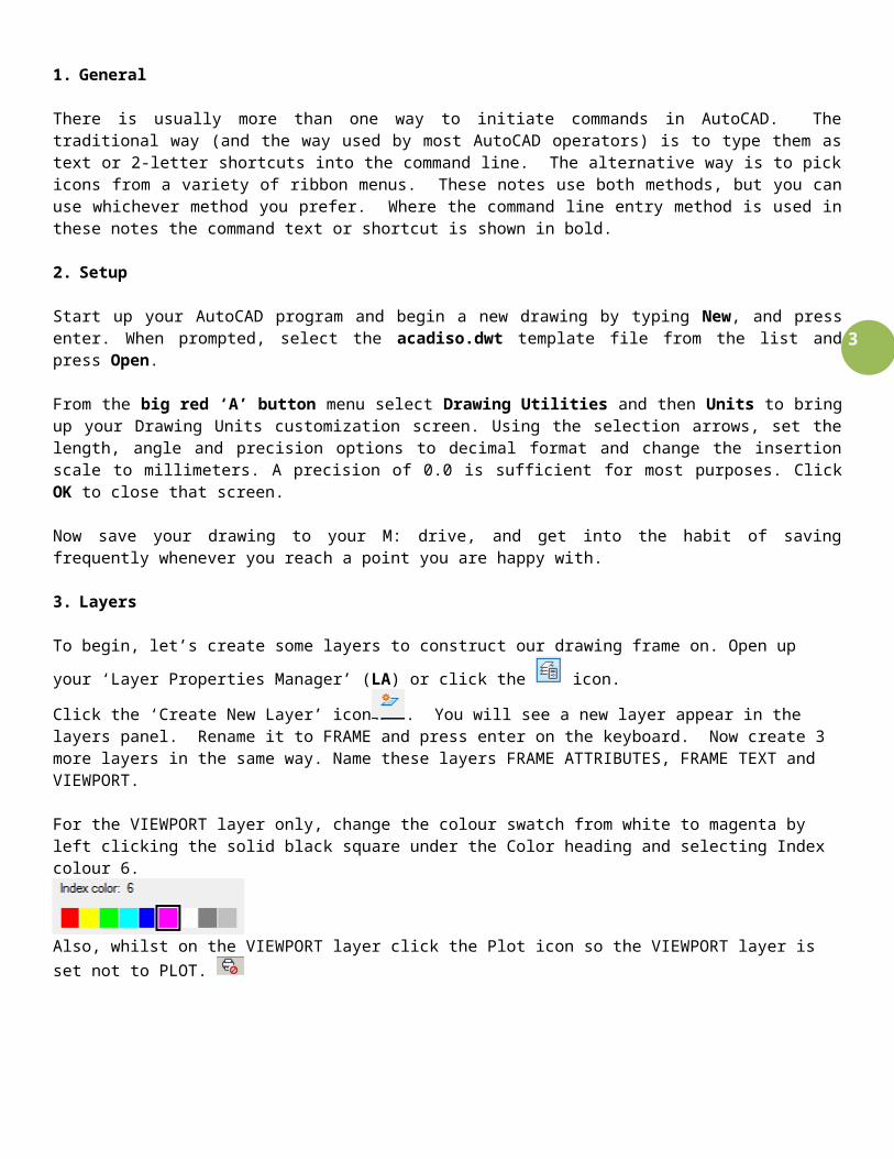
2. Setup
Start up your AutoCAD program and begin a new drawing by typing New, and press enter. When prompted, select the acadiso.dwt template file from the list and press Open.
From the big red ‘A’ button menu select Drawing Utilities and then Units to bring up your Drawing Units customization screen. Using the selection arrows, set the length, angle and precision options to decimal format and change the insertion scale to millimeters. A precision of 0.0 is sufficient for most purposes. Click OK to close that screen.
Now save your drawing to your M: drive, and get into the habit of saving frequently whenever you reach a point you are happy with.
3. Layers
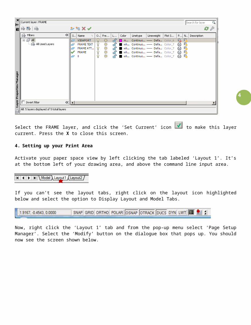
To begin, let’s create some layers to construct our drawing frame on. Open up your ‘Layer Properties Manager’ (LA) or
click the icon.
Click the ‘Create New Layer’ icon . You will see a new layer appear in the layers panel. Rename it to FRAME and press enter on the keyboard. Now create 3 more layers in the same way. Name these layers FRAME ATTRIBUTES, FRAME TEXT and VIEWPORT.
For the VIEWPORT layer only, change the colour swatch from white to magenta by left clicking the solid black square under the Color heading and selecting Index colour 6.
Also, whilst on the VIEWPORT layer click the Plot icon so the VIEWPORT layer is set not to PLOT.
3
Select the FRAME layer, and click the ‘Set Current’ icon to make this layer current. Press the X to close this screen.
4. Setting up your Print Area
Activate your paper space view by left clicking the tab labeled ‘Layout 1’. It’s at the bottom left of your drawing area, and above the command line input area.
If you can’t see the layout tabs, right click on the layout icon highlighted below and select the option to Display Layout and Model Tabs.
Now, right click the ‘Layout 1’ tab and from the pop-up menu select ‘Page Setup Manager’. Select the ‘Modify’ button on the dialogue box that pops up. You should now see the screen shown below.
As highlighted by the first star, find the DWG To PDF.pc3 option in the ‘Printer/plotter’ selection box. Once you have selected the device, you need to set the paper size according to the devices output capabilities. In this case, we’ll be using ISO A3 (420.00 x 297.00MM). Change the plot scale of the layout to 1:1 so that 1mm is equal to 1 drawing unit.
4
Select OK to close this box once you have set your paper size. You will now see that the size of the drawing area has changed to A3. There are 2 rectangles shown in your view. The solid rectangle is a viewport object, while the rectangle with a dashed line type represents the printable area for your print device and is non-selectable.
Delete the VIEWPORT (small solid rectangle) for now by left clicking on it and pressing the delete key. Alternatively, you
could select the ‘Erase’ icon , left clicking on the rectangle and pressing enter on the keyboard.
Anything outside of the dashed line will not print, so you must construct your drawing frame with this constraint in mind. The simple way to start your frame would be by drawing a rectangle just inside of the dashed line.
5. Drawing the Frame
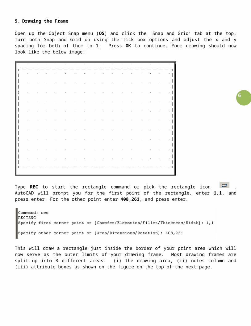
Open up the Object Snap menu (OS) and click the ‘Snap and Grid’ tab at the top. Turn both Snap and Grid on using the tick box options and adjust the x and y spacing for both of them to 1. Press OK to continue. Your drawing should now look like the below image:
Type REC to start the rectangle command or pick the rectangle icon . AutoCAD will prompt you for the first point of the rectangle, enter 1,1, and press enter. For the other point enter 408,261, and press enter.
This will draw a rectangle just inside the border of your print area which will now serve as the outer limits of your drawing frame. Most drawing frames are split up into 3 different areas: (i) the drawing area, (ii) notes column and (iii) attribute boxes as shown on the figure on the top of the next page.

5
Left click the rectangle you have just drawn and type explode or select the explode icon . This turns the rectangle
into 4 separate lines. Left click the right hand side vertical line and type offset or select the offset icon , press enter. Enter 60 as the offset distance, press enter, and left click on a point to the left side of that line. Select the bottom line and offset this upwards by 8, 16, 24, 50 & 76 (NB. all dims are mm). You will need to exit the command (ESC) after each offset operation.
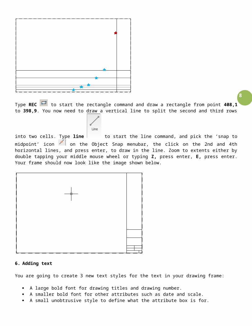
Type trim to start the trim command or select the trim icon . When prompted to select an object, select the vertical line highlighted with the red star in the figure below and hit enter. This is your cutting line. When prompted to select items to trim, pick the lines highlighted by blue stars (on the horizontal lines). Make sure your pick point is to the left of your cutting line. Press enter when trimming is finished.
6
Type REC to start the rectangle command and draw a rectangle from point 408,1 to 398,9. You now need to draw a
vertical line to split the second and third rows into two cells. Type line to start the line command, and pick the
‘snap to midpoint’ icon on the Object Snap menubar, the click on the 2nd and 4th horizontal lines, and press enter, to draw in the line. Zoom to extents either by double tapping your middle mouse wheel or typing Z, press enter, E, press enter. Your frame should now look like the image shown below.
6. Adding text
You are going to create 3 new text styles for the text in your drawing frame:
A large bold font for drawing titles and drawing number. A smaller bold font for other attributes such as date and scale. A small unobtrusive style to define what the attribute box is for.

7
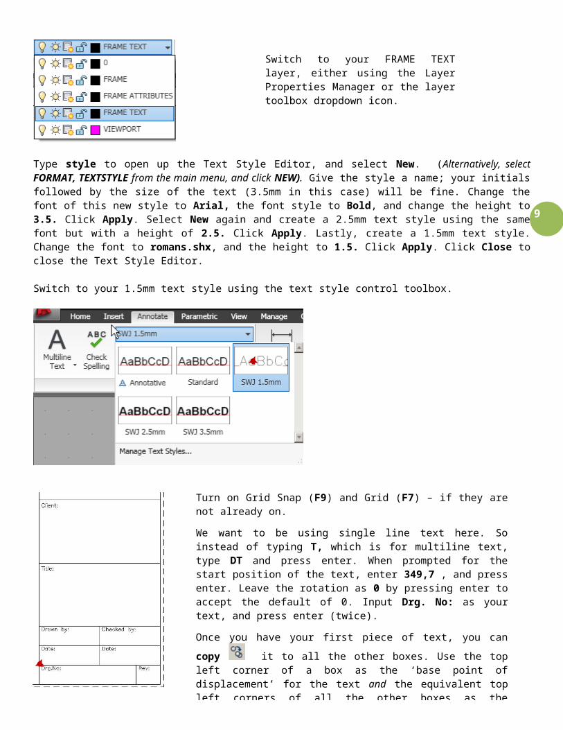
Type style to open up the Text Style Editor, and select New. (Alternatively, select FORMAT, TEXTSTYLE from the main menu, and click NEW). Give the style a name; your initials followed by the size of the text (3.5mm in this case) will be fine. Change the font of this new style to Arial, the font style to Bold, and change the height to 3.5. Click Apply. Select New again and create a 2.5mm text style using the same font but with a height of 2.5. Click Apply. Lastly, create a 1.5mm text style. Change the font to romans.shx, and the height to 1.5. Click Apply. Click Close to close the Text Style Editor.
Switch to your 1.5mm text style using the text style control toolbox.
Tip: By holding down shift and right clicking the mouse, you can access a dropdown menu for object snap. F3 turns snaps on or off.
Turn on Grid Snap (F9) and Grid (F7) – if they are not already on.
We want to be using single line text here. So instead of typing T, which is for multiline text, type DT and press enter. When prompted for the start position of the text, enter 349,7 , and press enter. Leave the rotation as 0 by pressing enter to accept the default of 0. Input Drg. No: as your text, and press enter (twice).
Once you have your first piece of text, you can copy it to all the other boxes. Use the top left corner of a box as the ‘base point of displacement’ for the text and the equivalent top left corners of all the other boxes as the destination point for all copies. Intersection and Endpoint should be turned on in your snap settings for this (OSNAP). This should be possible as a series of clicks in each required position.
Once you have text in all the upper left corners of your boxes you can modify the content of each text item by double clicking the text and writing something else. Change all the text to the values shown alongside.
Switch to your FRAME TEXT layer, either using the Layer Properties Manager or the layer toolbox dropdown icon.
8
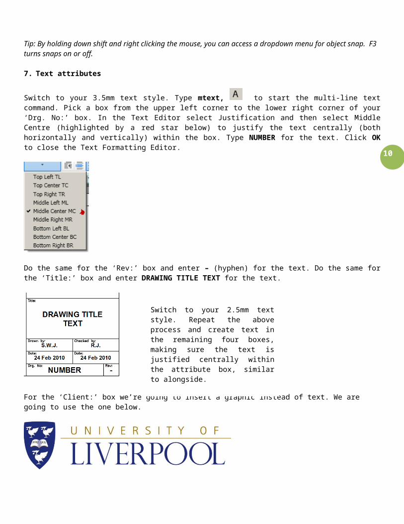
7. Text attributes
Switch to your 3.5mm text style. Type mtext, to start the multi-line text command. Pick a box from the upper left corner to the lower right corner of your ‘Drg. No:’ box. In the Text Editor select Justification and then select Middle Centre (highlighted by a red star below) to justify the text centrally (both horizontally and vertically) within the box. Type NUMBER for the text. Click OK to close the Text Formatting Editor.
Do the same for the ‘Rev:’ box and enter – (hyphen) for the text. Do the same for the ‘Title:’ box and enter DRAWING TITLE TEXT for the text.
For the ‘Client:’ box we’re going to insert a graphic instead of text. We are going to use the one below.
Download the University Logo graphic from the ENG106 module on VITAL (in the Assignment area), and save it to your
M: drive. Left click onto the image called ‘University Logo.JPG’ . To open the image file, right click onto the image and use ‘Save Target As….’.
Type imageattach. Browse to your M: drive and Open the University Logo.JPG file. The Attach Image dialogue box will then open. Uncheck the ‘Specify on-screen’ boxes for both ‘Insertion Point’ and ‘Scale’. Type an insertion point of 349,57 and a scale factor of 0.5, as on the below screen:
Switch to your 2.5mm text style. Repeat the above process and create text in the remaining four boxes, making sure the text is justified centrally within the attribute box, similar to alongside.
9
Remove the black border around the University Logo graphic by typing imageframe, then type 0 and press enter.
Select everything in the view by picking a crossing selection box or by pressing ctrl+a. Once everything is selected type block and press enter. Using the block definition box, give the block a name e.g. SWJ-A3 Title block. Press OK to continue. Selecting any part of your drawing frame now will result in the entire frame, including text, to be selected. It is effectively ‘grouped’. By double clicking the block, you can use the block editor to change its appearance and text entries. You can also right click the block and choose the option to edit it in place.
Your drawing frame is now complete, so save it with a suitable filename (your_initials-A3 Drawing Frame) for use in the future.
8. Viewports
Switch to your VIEWPORT layer.
A viewport is essentially a window that looks in through the paper space view into your model space. Model space is where you would draw the details for your designs at 1:1 scale. You then use a viewport to view certain parts of it at a convenient scale. You can have multiple viewports in a paper space layout with differing scales.
Press and hold the left Alt key. You should see small underscores on certain letters of all of the menu items at the top of your screen. While keeping it pressed, type vv1 slowly. This should navigate you through the menus and select the create ‘1 Viewport’ option for you. When prompted for the first corner of the viewport, enter 2,22 as the coordinate, and press enter. For the second corner enter 220,260, and press enter. Create another viewport in the same way but with the coordinates 235,124 and 344,243 for its corners. The second viewport is exactly half the size of the first.
Double left click inside the first and larger viewport to activate it – notice the magenta border becomes a thick line. Type insert to bring up the insert block menu and select your newly created title block from the dropdown menu. Click OK to insert the block at coordinate 0.0 and at scale 1:1. Double tap your middle mouse wheel or type Z enter, E enter to zoom the viewport to extents. Left click in the smaller viewport and zoom that to extents in the same way.
Double click outside of the viewport, in any area not covered by another viewport, to reactivate paper space.
10
Press ctrl+1 to open the properties menu. Select the large viewport by left clicking the magenta rectangle that represents its edge. The properties for the viewport will now be visible in the properties menu.
Under the Miscellaneous section of the viewports properties panel, change the Custom scale to 0.5 and change the Display locked option to yes.
Press ctrl+p to bring up the print screen. Select the preview option to see how your drawing will look once printed. If you’re happy, print the PDF and save it using a suitable filename.
S W Jones10 March 2011
NVFIRST AND SECOND LINE/POINT
Press escape to deselect the large viewport and left click the border of the smaller viewport. You should now use the properties menu to change the Custom scale for the small viewport to 0.25 and set the Display locked option to yes.
Double clicking in either of the viewports now, and trying to zoom or pan around using the middle mouse wheel or commands, will not move the view. It will be the paper space layout that moves around.
Return to your paper space.