Embed Size (px)
Citation preview

2018
Software RepublicSoftware Republic
TM
RAUTOCAD® EDITION

Copyright © 2018 Software Republic, L.L.P. All rights reserved. This documentation and the associated software are the property of Software Republic, L.L.P. and are on loan to the user under the terms of the License Agreement. Unauthorized copying or use of this documentation, the software, or any associated materials is contrary to the property rights of Software Republic and in violation of state and federal law. This document describes the use of RainCAD. Software Republic L.L.P. reserves the right to enhance, improve and revise its products without further notice. The information in this manual is subject to change without notice and does not represent a commitment on the part of Software Republic, L.L.P. Software Republic, L.L.P. assumes no liability for any errors or inaccuracies that may appear in this document. RainCAD is a trademark of Software Republic, L.L.P. AutoCAD is a registered trademark of Autodesk. Microsoft and Windows are registered trademarks of Microsoft Corporation. All other product names are trademarks of their respective owners in the United States and/or other countries. Software Republic, L.L.P. Internet: www.softwarerepublic.com Sales E-Mail: [email protected] Sales Number: (936) 372-9884 Support: http://www.softwarerepublic.com/support.aspx Printed in the United States of America

ii RainCAD
This page is intentionally left blank.
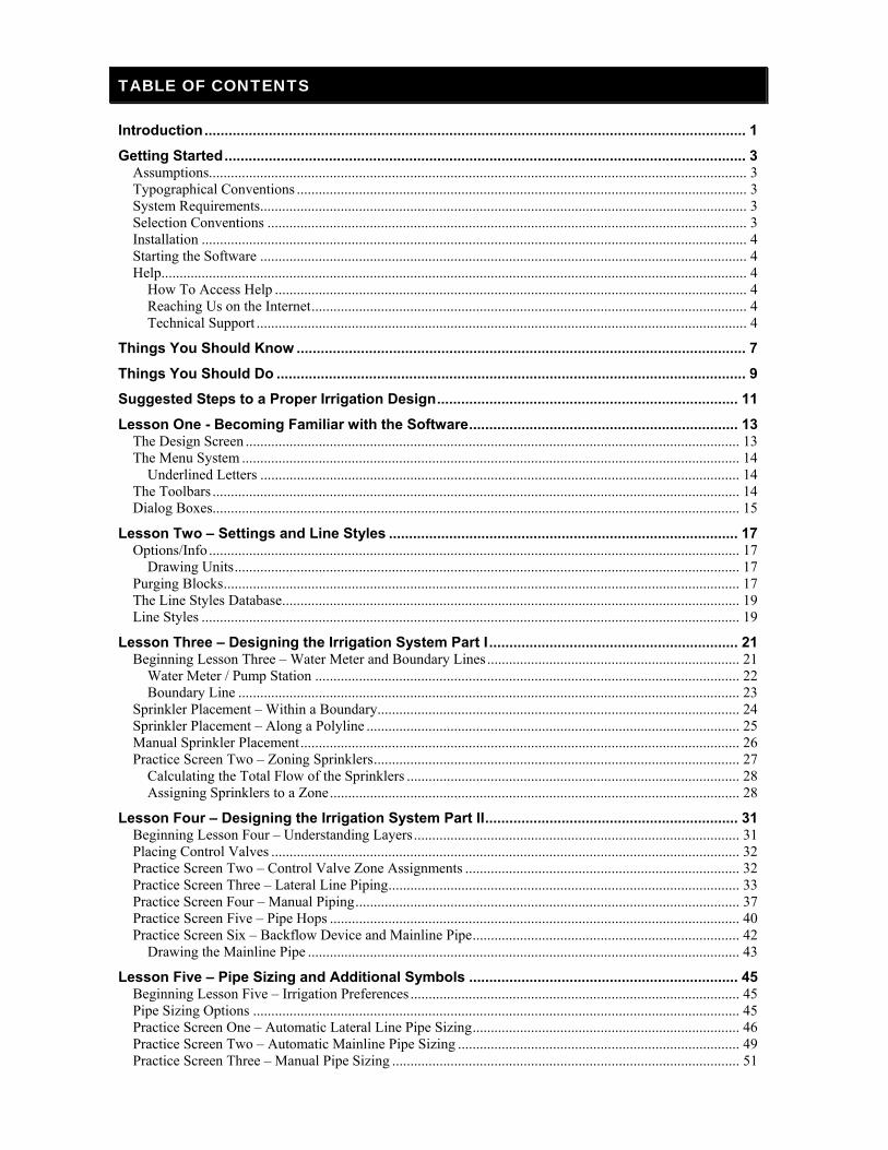
TABLE OF CONTENTS
Introduction ....................................................................................................................................... 1
Getting Started .................................................................................................................................. 3 Assumptions................................................................................................................................................... 3 Typographical Conventions ........................................................................................................................... 3 System Requirements..................................................................................................................................... 3 Selection Conventions ................................................................................................................................... 3 Installation ..................................................................................................................................................... 4 Starting the Software ..................................................................................................................................... 4 Help................................................................................................................................................................ 4
How To Access Help ................................................................................................................................. 4 Reaching Us on the Internet ....................................................................................................................... 4 Technical Support ...................................................................................................................................... 4
Things You Should Know ................................................................................................................ 7
Things You Should Do ..................................................................................................................... 9
Suggested Steps to a Proper Irrigation Design ........................................................................... 11
Lesson One - Becoming Familiar with the Software ................................................................... 13 The Design Screen ....................................................................................................................................... 13 The Menu System ........................................................................................................................................ 14
Underlined Letters ................................................................................................................................... 14 The Toolbars ................................................................................................................................................ 14 Dialog Boxes................................................................................................................................................ 15
Lesson Two – Settings and Line Styles ....................................................................................... 17 Options/Info ................................................................................................................................................. 17
Drawing Units .......................................................................................................................................... 17 Purging Blocks ............................................................................................................................................. 17 The Line Styles Database ............................................................................................................................. 19 Line Styles ................................................................................................................................................... 19
Lesson Three – Designing the Irrigation System Part I .............................................................. 21 Beginning Lesson Three – Water Meter and Boundary Lines ..................................................................... 21
Water Meter / Pump Station .................................................................................................................... 22 Boundary Line ......................................................................................................................................... 23
Sprinkler Placement – Within a Boundary ................................................................................................... 24 Sprinkler Placement – Along a Polyline ...................................................................................................... 25 Manual Sprinkler Placement ........................................................................................................................ 26 Practice Screen Two – Zoning Sprinklers .................................................................................................... 27
Calculating the Total Flow of the Sprinklers ........................................................................................... 28 Assigning Sprinklers to a Zone ................................................................................................................ 28
Lesson Four – Designing the Irrigation System Part II ............................................................... 31 Beginning Lesson Four – Understanding Layers ......................................................................................... 31 Placing Control Valves ................................................................................................................................ 32 Practice Screen Two – Control Valve Zone Assignments ........................................................................... 32 Practice Screen Three – Lateral Line Piping ................................................................................................ 33 Practice Screen Four – Manual Piping ......................................................................................................... 37 Practice Screen Five – Pipe Hops ................................................................................................................ 40 Practice Screen Six – Backflow Device and Mainline Pipe ......................................................................... 42
Drawing the Mainline Pipe ...................................................................................................................... 43
Lesson Five – Pipe Sizing and Additional Symbols ................................................................... 45 Beginning Lesson Five – Irrigation Preferences .......................................................................................... 45 Pipe Sizing Options ..................................................................................................................................... 45 Practice Screen One – Automatic Lateral Line Pipe Sizing ......................................................................... 46 Practice Screen Two – Automatic Mainline Pipe Sizing ............................................................................. 49 Practice Screen Three – Manual Pipe Sizing ............................................................................................... 51
iv RainCAD
Practice Screen Four – Controllers and Accessory Symbols ........................................................................ 52 Controller/Station Assignments .................................................................................................................... 54 Valve Notations ............................................................................................................................................ 54 Placing Sleeve Symbols ............................................................................................................................... 55 Irrigation Installation Details ........................................................................................................................ 55
Lesson Six – Landscape Design .................................................................................................... 57 Searching for Plant Material ......................................................................................................................... 57 Practice Screen One – Placing Plant Symbols .............................................................................................. 57 Plant Placement – Along a Polyline ............................................................................................................. 60 Practice Screen Two - Plant Placement Within a Boundary ......................................................................... 62 Deleting or Replacing Plants ........................................................................................................................ 64 Practice Screen Three – Combining Plant Symbols ..................................................................................... 64 Shadowing .................................................................................................................................................... 66 Practice Screen Four - Plant Notations ......................................................................................................... 67 Fill Materials ................................................................................................................................................ 69 Miscellaneous Symbols ................................................................................................................................ 70 Auto Symbol Layout .................................................................................................................................... 71 Landscape Installation Details ...................................................................................................................... 72
Lesson Seven – Calculations ......................................................................................................... 73 Beginning Lesson Seven – Hydraulic Calculations ...................................................................................... 73 Distribution ................................................................................................................................................... 74 Practice Screen Two – Material/Estimate ..................................................................................................... 76 Legends ........................................................................................................................................................ 79
Lesson Eight – Modifying the Databases ..................................................................................... 81 The Sprinklers Database ............................................................................................................................... 81
Adding a Sprinkler to the Database .......................................................................................................... 81 Performance Data ..................................................................................................................................... 82 Distribution Data ...................................................................................................................................... 82
Sprinkler Palette Assignments ...................................................................................................................... 84 Tied Assemblies and Supplies ...................................................................................................................... 84 The Plants Database ..................................................................................................................................... 85
Adding a Plant to the Database ................................................................................................................. 86 Plant Size Data ......................................................................................................................................... 86 Species Database ...................................................................................................................................... 88 Plant Palette Assignments ........................................................................................................................ 89
Conclusion ....................................................................................................................................... 91
Appendix A – Customizing Symbols ............................................................................................. 93 Customizing Existing Symbols .................................................................................................................... 94 Creating New Symbols ................................................................................................................................. 95
Index ................................................................................................................................................. 97

INTRODUCTION
Welcome to RainCAD! RainCAD is a powerful software tool created to fit your irrigation, landscape, accent lighting or drainage design needs. The software comes complete with predefined symbols, equipment and plant placement functions, pipe and accent lighting wire sizing capabilities, material takeoffs, and much more. RainCAD will allow you to create irrigation and/or landscape designs for both residential and commercial projects. With the software, you can quickly calculate a complete material takeoff, develop estimates and proposals, and generate complete symbol legends. Best of all, the software is easy to learn and use, offering on-line help screens for virtually every command. RainCAD is based on AutoCAD® 2018 (64-bit). The software requires a full-working version of AutoCAD® 2018 (64-bit) to be installed on the computer system for the program to operate. The software will not operate with any version of AutoCAD® LT. The software will only run with a 64-bit version of AutoCAD® 2018. Thank you for your purchase of RainCAD. We value your business and are proud you have chosen our software to assist you with your design needs.

2 RainCAD
This page is intentionally left blank.
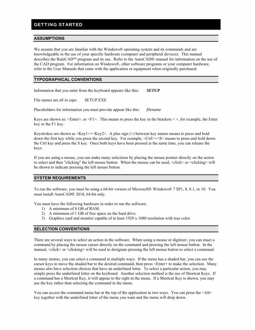
GETTING STARTED
ASSUMPTIONS
We assume that you are familiar with the Windows® operating system and its commands and are knowledgeable in the use of your specific hardware (computer and peripheral devices). This manual describes the RainCAD program and its use. Refer to the AutoCAD manual for information on the use of the CAD program. For information on Windows®, other software programs or your computer hardware, refer to the User Manuals that came with the application or equipment when originally purchased.
TYPOGRAPHICAL CONVENTIONS
Information that you enter from the keyboard appears like this: SETUP File names are all in caps: SETUP.EXE Placeholders for information you must provide appear like this: filename Keys are shown as: <Enter>, or <F1>. This means to press the key in the brackets < >, for example, the Enter key or the F1 key. Keystrokes are shown as <Key1>+<Key2>. A plus sign (+) between key names means to press and hold down the first key while you press the second key. For example, <Ctrl>+<S> means to press and hold down the Ctrl key and press the S key. Once both keys have been pressed at the same time, you can release the keys. If you are using a mouse, you can make many selections by placing the mouse pointer directly on the action to select and then "clicking" the left mouse button. When the mouse can be used, <click> or <clicking> will be shown to indicate pressing the left mouse button.
SYSTEM REQUIREMENTS
To run the software, you must be using a 64-bit version of Microsoft Windows® 7 SP1, 8, 8.1, or 10. You must install AutoCAD 2018, 64-bit only. You must have the following hardware in order to run the software:
1) A minimum of 8 GB of RAM. 2) A minimum of 1 GB of free space on the hard drive. 3) Graphics card and monitor capable of at least 1920 x 1080 resolution with true color.
SELECTION CONVENTIONS
There are several ways to select an action in the software. When using a mouse or digitizer, you can enact a command by placing the mouse cursor directly on the command and pressing the left mouse button. In the manual, <click> or <clicking> will be used to designate pressing the left mouse button to select a command. In many menus, you can select a command in multiple ways. If the menu has a shaded bar, you can use the cursor keys to move the shaded bar to the desired command, then press <Enter> to make the selection. Many menus also have selection choices that have an underlined letter. To select a particular action, you may simply press the underlined letter on the keyboard. Another selection method is the use of Shortcut Keys. If a command has a Shortcut Key, it will appear to the right in the menu. If a Shortcut Key is shown, you may use the key rather than selecting the command in the menu. You can access the command menu bar at the top of the application in two ways. You can press the <Alt> key together with the underlined letter of the menu you want and the menu will drop down.
4 RainCAD
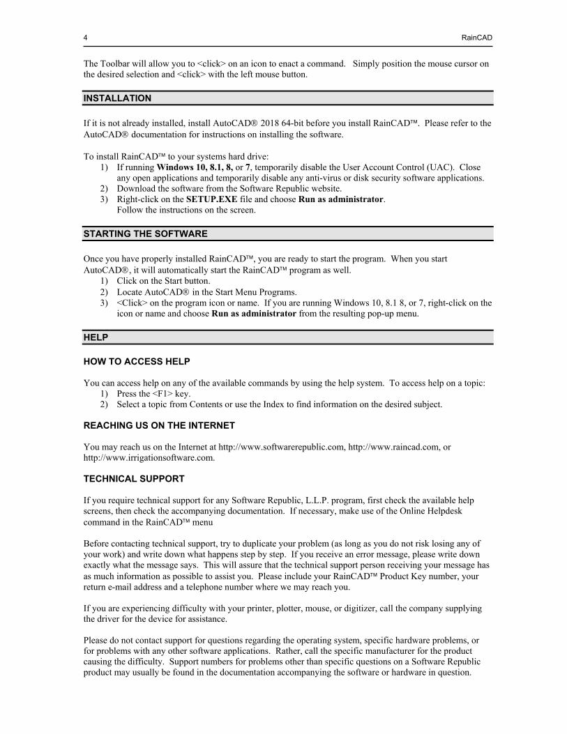
The Toolbar will allow you to <click> on an icon to enact a command. Simply position the mouse cursor on the desired selection and <click> with the left mouse button.
INSTALLATION
If it is not already installed, install AutoCAD 2018 64-bit before you install RainCAD. Please refer to the AutoCAD documentation for instructions on installing the software. To install RainCAD to your systems hard drive:
1) If running Windows 10, 8.1, 8, or 7, temporarily disable the User Account Control (UAC). Close any open applications and temporarily disable any anti-virus or disk security software applications.
2) Download the software from the Software Republic website. 3) Right-click on the SETUP.EXE file and choose Run as administrator.
Follow the instructions on the screen.
STARTING THE SOFTWARE
Once you have properly installed RainCAD, you are ready to start the program. When you start AutoCAD, it will automatically start the RainCAD program as well.
1) Click on the Start button. 2) Locate AutoCAD in the Start Menu Programs. 3) <Click> on the program icon or name. If you are running Windows 10, 8.1 8, or 7, right-click on the
icon or name and choose Run as administrator from the resulting pop-up menu.
HELP
HOW TO ACCESS HELP You can access help on any of the available commands by using the help system. To access help on a topic:
1) Press the <F1> key. 2) Select a topic from Contents or use the Index to find information on the desired subject.
REACHING US ON THE INTERNET You may reach us on the Internet at http://www.softwarerepublic.com, http://www.raincad.com, or http://www.irrigationsoftware.com. TECHNICAL SUPPORT If you require technical support for any Software Republic, L.L.P. program, first check the available help screens, then check the accompanying documentation. If necessary, make use of the Online Helpdesk command in the RainCAD menu Before contacting technical support, try to duplicate your problem (as long as you do not risk losing any of your work) and write down what happens step by step. If you receive an error message, please write down exactly what the message says. This will assure that the technical support person receiving your message has as much information as possible to assist you. Please include your RainCAD Product Key number, your return e-mail address and a telephone number where we may reach you. If you are experiencing difficulty with your printer, plotter, mouse, or digitizer, call the company supplying the driver for the device for assistance. Please do not contact support for questions regarding the operating system, specific hardware problems, or for problems with any other software applications. Rather, call the specific manufacturer for the product causing the difficulty. Support numbers for problems other than specific questions on a Software Republic product may usually be found in the documentation accompanying the software or hardware in question.

Getting Started 5
YOU MUST HAVE A VALID PRODUCT KEY NUMBER AND HAVE
REGISTERED YOUR SOFTWARE TO RECEIVE TECHNICAL SUPPORT.

6 RainCAD
This page is intentionally left blank.

THINGS YOU SHOULD KNOW
You should know a few things before you begin the design process: 1) RainCAD is based on AutoCAD® 2018 (64-bit only). The software requires AutoCAD 2018 to
be installed on the computer system for the program to operate. The software will not operate with any version of AutoCAD® LT.
2) We recommend at least a 20-inch monitor with a screen resolution setting of no less than 1920 x
1080. Refer to the help in Microsoft Windows® for more information on changing the display resolution of your monitor.
3) You can receive help on any command in the program by accessing the Contents and Index from the
Help menu or by pressing the <F1> key.
4) All of the commands used in drafting the property are found in AutoCAD® except for the Line Styles and Auto Symbol Layout commands found in the Symbols menu of RainCAD.
5) If the Drawing Units in AutoCAD® are set to Architectural or Engineering, in most cases the
Drawing Units in the RainCAD Options/Info menu should be set to Inches. If the AutoCAD® Drawing Units are set to Decimal, the RainCAD Drawing Units should usually be set to Feet. For a quick reference, the current units of measurement will be displayed in the Title Bar of each RainCAD dialog box as (ft), (in), (mm), (cm), or (m).
6) All equipment and materials are placed on the drawing screen by selecting the appropriate submenu
and command from the Symbols menu. 7) You may find additional miscellaneous symbols for title blocks, north arrows, vehicles, people and
more in the Symbols menu as well. You may place these symbols on the drawing screen at any time during the design process.
8) RainCAD inserts all symbols as AutoCAD® blocks. A block can be composed of multiple objects
drawn on several layers with various colors, line types, and line weight properties. To change the characteristics of the symbol, you must first purge all references to the block from the design screen. To purge means to remove, clear or otherwise get rid of something. You cannot purge a block if the block is in use on the design screen. You must first delete any references to the block on the screen, meaning you must erase the symbols from the drawing.
9) When the US Units/Metric setting is configured to Millimeters, Centimeters or Meters in the
Drafting Preferences dialog box, it is necessary to enter data with the period as the decimal indicator and not the comma. For example; 30,13 meters should be entered as 30.13.
10) When your drawing is printed or plotted to a 1” = 10’ or 1” = 20’ scale, the symbols are normally
legible. If the drawing is output to a smaller scale, such as a 1” = 40’ scale, the symbols may be too small to be visible. It is highly recommended that you consider the desired output scale of the drawing and adjust the Symbol Scale Factor before you begin a design.
11) RainCAD calculates the length and type of pipe on a drawing screen based on the layer on which
the pipe is drawn. If you change the layer assignment of any pipe on the drawing, the pipe will not be included in the material takeoff or estimate/proposal.
12) For RainCAD to know that a piece of pipe is connected to a sprinkler, control valve, backflow
device or point of connection, it must be connected properly to the symbol. To be more specific, the pipe must be drawn within 0.5 feet of the handle or insertion point of the symbol.
13) AutoCAD will allow you to open more than one drawing screen at a time. When you finish a
lesson in the tutorial and proceed to the next lesson, you will need to close the current tutorial practice screen. When closing the practice screen, you will have the opportunity to save any

8 RainCAD
changes to the drawing. If you or anyone else is going to work through the lesson at another time, DO NOT SAVE the drawing.
When proceeding from one lesson in the tutorial to another: 1) On the File menu in AutoCAD, <click> Close. 2) A message will appear on the screen asking if you want to "save changes to" the current drawing
file. Answer NO by <clicking> on the No button with the mouse. 3) On the Help menu in RainCAD, <click> on Tutorial. 4) On the Tutorial submenu, select the desired lesson. 5) On the Lesson submenu, select the desired Practice Screen.
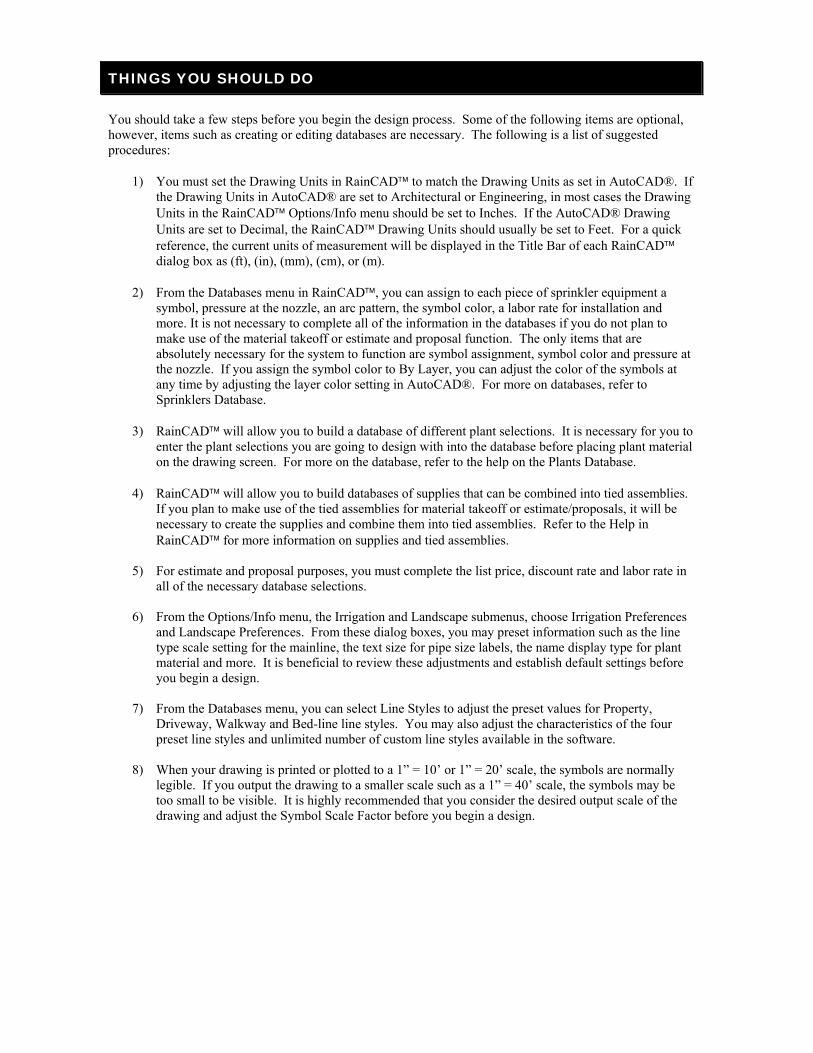
THINGS YOU SHOULD DO
You should take a few steps before you begin the design process. Some of the following items are optional, however, items such as creating or editing databases are necessary. The following is a list of suggested procedures:
1) You must set the Drawing Units in RainCAD to match the Drawing Units as set in AutoCAD®. If the Drawing Units in AutoCAD® are set to Architectural or Engineering, in most cases the Drawing Units in the RainCAD Options/Info menu should be set to Inches. If the AutoCAD® Drawing Units are set to Decimal, the RainCAD Drawing Units should usually be set to Feet. For a quick reference, the current units of measurement will be displayed in the Title Bar of each RainCAD dialog box as (ft), (in), (mm), (cm), or (m).
2) From the Databases menu in RainCAD, you can assign to each piece of sprinkler equipment a symbol, pressure at the nozzle, an arc pattern, the symbol color, a labor rate for installation and more. It is not necessary to complete all of the information in the databases if you do not plan to make use of the material takeoff or estimate and proposal function. The only items that are absolutely necessary for the system to function are symbol assignment, symbol color and pressure at the nozzle. If you assign the symbol color to By Layer, you can adjust the color of the symbols at any time by adjusting the layer color setting in AutoCAD®. For more on databases, refer to Sprinklers Database.
3) RainCAD will allow you to build a database of different plant selections. It is necessary for you to
enter the plant selections you are going to design with into the database before placing plant material on the drawing screen. For more on the database, refer to the help on the Plants Database.
4) RainCAD will allow you to build databases of supplies that can be combined into tied assemblies.
If you plan to make use of the tied assemblies for material takeoff or estimate/proposals, it will be necessary to create the supplies and combine them into tied assemblies. Refer to the Help in RainCAD for more information on supplies and tied assemblies.
5) For estimate and proposal purposes, you must complete the list price, discount rate and labor rate in
all of the necessary database selections. 6) From the Options/Info menu, the Irrigation and Landscape submenus, choose Irrigation Preferences
and Landscape Preferences. From these dialog boxes, you may preset information such as the line type scale setting for the mainline, the text size for pipe size labels, the name display type for plant material and more. It is beneficial to review these adjustments and establish default settings before you begin a design.
7) From the Databases menu, you can select Line Styles to adjust the preset values for Property,
Driveway, Walkway and Bed-line line styles. You may also adjust the characteristics of the four preset line styles and unlimited number of custom line styles available in the software.
8) When your drawing is printed or plotted to a 1” = 10’ or 1” = 20’ scale, the symbols are normally
legible. If you output the drawing to a smaller scale such as a 1” = 40’ scale, the symbols may be too small to be visible. It is highly recommended that you consider the desired output scale of the drawing and adjust the Symbol Scale Factor before you begin a design.

10 RainCAD
This page is intentionally left blank.
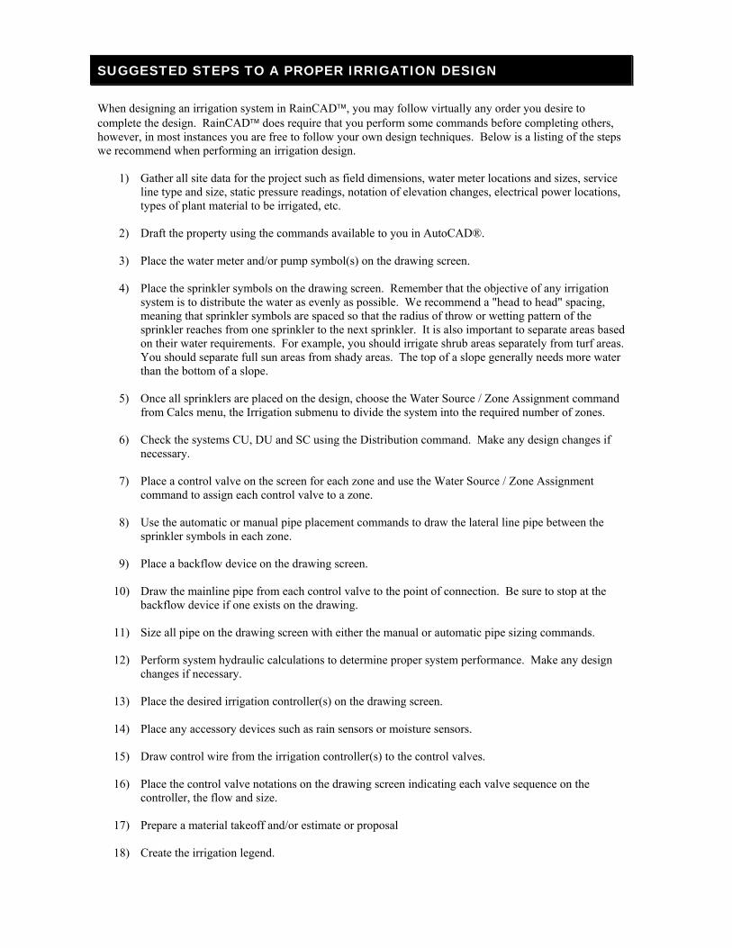
SUGGESTED STEPS TO A PROPER IRRIGATION DESIGN
When designing an irrigation system in RainCAD, you may follow virtually any order you desire to complete the design. RainCAD does require that you perform some commands before completing others, however, in most instances you are free to follow your own design techniques. Below is a listing of the steps we recommend when performing an irrigation design.
1) Gather all site data for the project such as field dimensions, water meter locations and sizes, service line type and size, static pressure readings, notation of elevation changes, electrical power locations, types of plant material to be irrigated, etc.
2) Draft the property using the commands available to you in AutoCAD®. 3) Place the water meter and/or pump symbol(s) on the drawing screen. 4) Place the sprinkler symbols on the drawing screen. Remember that the objective of any irrigation
system is to distribute the water as evenly as possible. We recommend a "head to head" spacing, meaning that sprinkler symbols are spaced so that the radius of throw or wetting pattern of the sprinkler reaches from one sprinkler to the next sprinkler. It is also important to separate areas based on their water requirements. For example, you should irrigate shrub areas separately from turf areas. You should separate full sun areas from shady areas. The top of a slope generally needs more water than the bottom of a slope.
5) Once all sprinklers are placed on the design, choose the Water Source / Zone Assignment command
from Calcs menu, the Irrigation submenu to divide the system into the required number of zones. 6) Check the systems CU, DU and SC using the Distribution command. Make any design changes if
necessary. 7) Place a control valve on the screen for each zone and use the Water Source / Zone Assignment
command to assign each control valve to a zone. 8) Use the automatic or manual pipe placement commands to draw the lateral line pipe between the
sprinkler symbols in each zone. 9) Place a backflow device on the drawing screen.
10) Draw the mainline pipe from each control valve to the point of connection. Be sure to stop at the backflow device if one exists on the drawing.
11) Size all pipe on the drawing screen with either the manual or automatic pipe sizing commands. 12) Perform system hydraulic calculations to determine proper system performance. Make any design
changes if necessary. 13) Place the desired irrigation controller(s) on the drawing screen. 14) Place any accessory devices such as rain sensors or moisture sensors. 15) Draw control wire from the irrigation controller(s) to the control valves. 16) Place the control valve notations on the drawing screen indicating each valve sequence on the
controller, the flow and size. 17) Prepare a material takeoff and/or estimate or proposal 18) Create the irrigation legend.

12 RainCAD
19) Place the legend on the drawing screen. It may be necessary to create a separate drawing for the details and legends to prevent cluttering the drawing.
20) Add any notations as needed to the drawing screen such as "This drawing is diagrammatic and
piping is shown in hardscape areas for clarity only", or "Place quick coupler valves every 100' O.C." 21) Using the tools available in AutoCAD, add any detail such as text or hatching patterns to give the
drawing a more professional appearance. 22) Print or plot the completed drawing and detail or legend page(s).
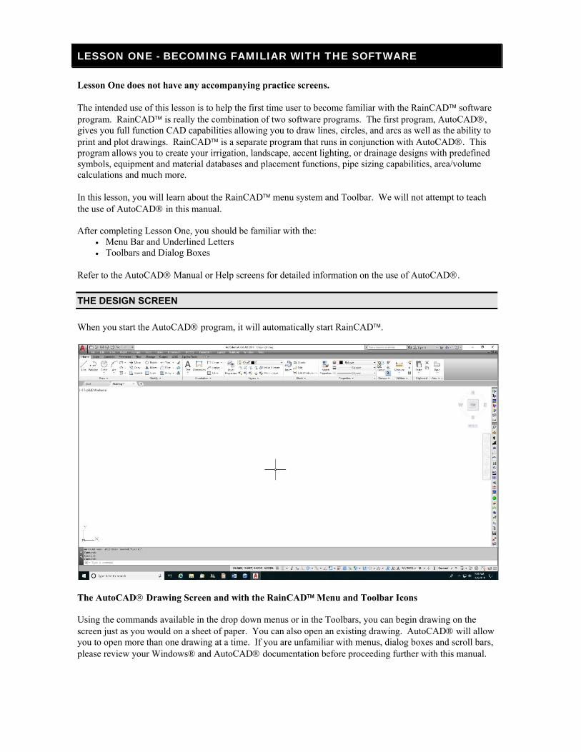
LESSON ONE - BECOMING FAMILIAR WITH THE SOFTWARE
Lesson One does not have any accompanying practice screens. The intended use of this lesson is to help the first time user to become familiar with the RainCAD software program. RainCAD is really the combination of two software programs. The first program, AutoCAD, gives you full function CAD capabilities allowing you to draw lines, circles, and arcs as well as the ability to print and plot drawings. RainCAD is a separate program that runs in conjunction with AutoCAD. This program allows you to create your irrigation, landscape, accent lighting, or drainage designs with predefined symbols, equipment and material databases and placement functions, pipe sizing capabilities, area/volume calculations and much more. In this lesson, you will learn about the RainCAD menu system and Toolbar. We will not attempt to teach the use of AutoCAD in this manual. After completing Lesson One, you should be familiar with the:
Menu Bar and Underlined Letters Toolbars and Dialog Boxes
Refer to the AutoCAD Manual or Help screens for detailed information on the use of AutoCAD.
THE DESIGN SCREEN
When you start the AutoCAD program, it will automatically start RainCAD.
The AutoCAD Drawing Screen and with the RainCAD Menu and Toolbar Icons Using the commands available in the drop down menus or in the Toolbars, you can begin drawing on the screen just as you would on a sheet of paper. You can also open an existing drawing. AutoCAD will allow you to open more than one drawing at a time. If you are unfamiliar with menus, dialog boxes and scroll bars, please review your Windows® and AutoCAD documentation before proceeding further with this manual.
14 RainCAD
COMMAND LINE
The Command Line at the bottom of the AutoCAD screen allows you to enact AutoCAD, RainCAD commands and also displays options or information about the selected command. You will refer to the Command Line often during the design process. Commands in RainCAD such as Boundary Line and Symbol Placement will use the Command Line to display additional information to assist you in completing the command.
THE RAINCAD MENU SYSTEM
The RainCAD Menu system is located the AutoCAD® Title Bar. The Menu system includes the entire drop down menu selections, which contain all of the commands available in the program. Commands followed by an arrow (►) indicate a secondary menu exists containing more command selections. UNDERLINED LETTERS You can access the Menu system by <clicking> on a selection with the mouse, or you may press the <Alt> key to access the Menu system and then press the underlined letter in the menu name. Once a menu is open, the command selections are available. You can select a command by <clicking> on the selection with the mouse, or you can press the underlined letter in the command name.
THE RAINCAD TOOLBARS
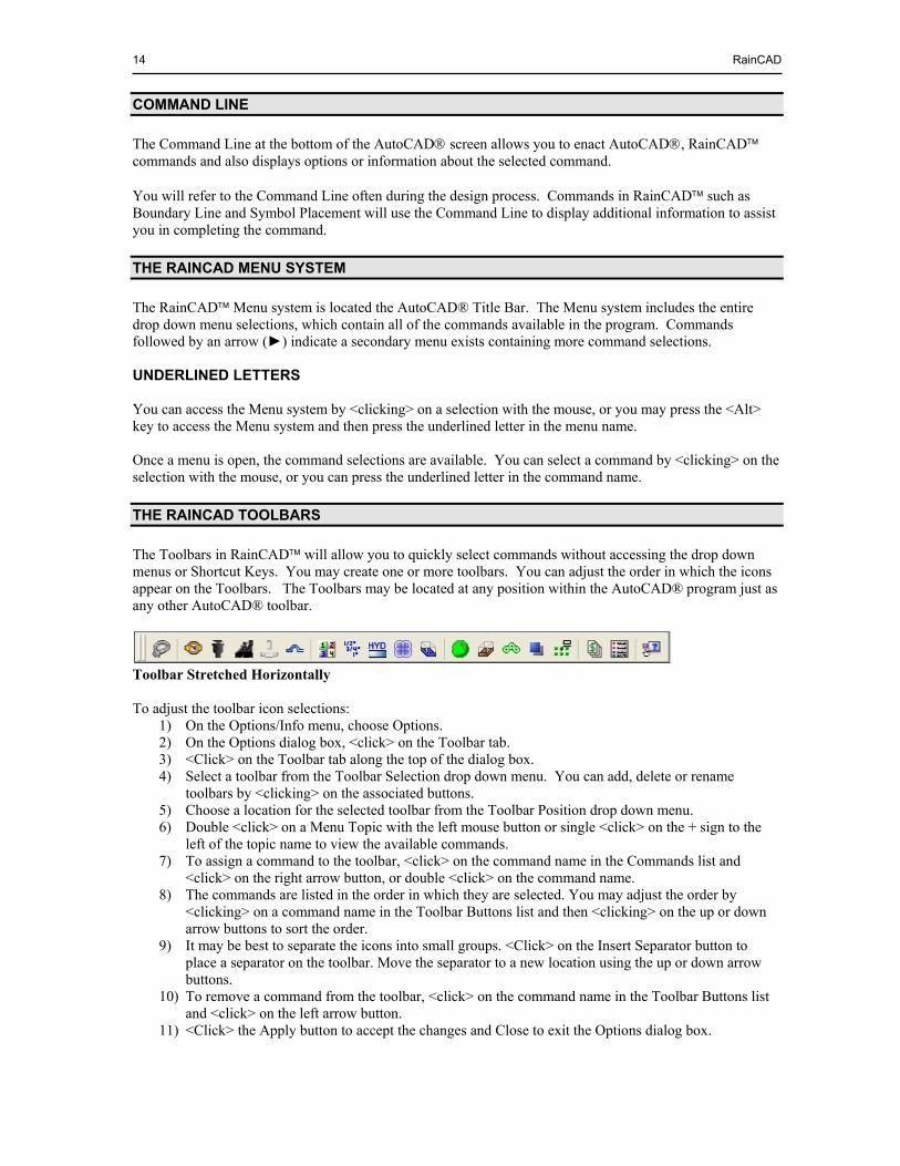
The Toolbars in RainCAD will allow you to quickly select commands without accessing the drop down menus or Shortcut Keys. You may create one or more toolbars. You can adjust the order in which the icons appear on the Toolbars. The Toolbars may be located at any position within the AutoCAD® program just as any other AutoCAD® toolbar.
Toolbar Stretched Horizontally To adjust the toolbar icon selections:
1) On the Options/Info menu, choose Options. 2) On the Options dialog box, <click> on the Toolbar tab. 3) <Click> on the Toolbar tab along the top of the dialog box. 4) Select a toolbar from the Toolbar Selection drop down menu. You can add, delete or rename
toolbars by <clicking> on the associated buttons. 5) Choose a location for the selected toolbar from the Toolbar Position drop down menu. 6) Double <click> on a Menu Topic with the left mouse button or single <click> on the + sign to the
left of the topic name to view the available commands. 7) To assign a command to the toolbar, <click> on the command name in the Commands list and
<click> on the right arrow button, or double <click> on the command name. 8) The commands are listed in the order in which they are selected. You may adjust the order by
<clicking> on a command name in the Toolbar Buttons list and then <clicking> on the up or down arrow buttons to sort the order.
9) It may be best to separate the icons into small groups. <Click> on the Insert Separator button to place a separator on the toolbar. Move the separator to a new location using the up or down arrow buttons.
10) To remove a command from the toolbar, <click> on the command name in the Toolbar Buttons list and <click> on the left arrow button.
11) <Click> the Apply button to accept the changes and Close to exit the Options dialog box.
Things You Should Know 15
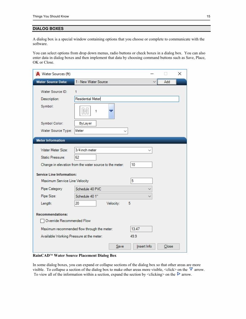
DIALOG BOXES
A dialog box is a special window containing options that you choose or complete to communicate with the software. You can select options from drop down menus, radio buttons or check boxes in a dialog box. You can also enter data in dialog boxes and then implement that data by choosing command buttons such as Save, Place, OK or Close.
RainCAD Water Source Placement Dialog Box In some dialog boxes, you can expand or collapse sections of the dialog box so that other areas are more visible. To collapse a section of the dialog box to make other areas more visible, <click> on the arrow. To view all of the information within a section, expand the section by <clicking> on the arrow.

16 RainCAD
This page is intentionally left blank.
LESSON TWO – SETTINGS AND LINE STYLES
Lesson Two does not have any accompanying practice screens. Estimated time to complete: 1/2 hour This manual assumes that you are familiar with drafting in AutoCAD. We will not attempt to teach the use of AutoCAD itself for drafting the property. However, we will cover several commands within RainCAD and AutoCAD that may be of use during the drafting process. Lesson Two explains the necessary Units of Measurement settings and will demonstrate the basic use of the Line Styles commands found in the Symbols menu. You will also learn about the Line Styles database.
After completing Lesson Two, you should be familiar with the:
Drawing Units AutoCAD Purge Command Line Styles Database Line Styles
OPTIONS/INFO – DRAWING UNITS
Before you begin drafting the property or designing an irrigation or landscape project, it is important for you to set the units of measurement for the drawing. All equipment and plant material symbols are scaled based on this setting. Prior to setting the units of measurement in RainCAD, check to see what the Units of measurement are set to in AutoCAD. If the Drawing Units in AutoCAD are set to Architectural or Engineering, in most cases the Drawing Units in RainCAD should be set to Inches. If the Drawing Units in AutoCAD are set to Decimal, the Drawing Units in RainCAD should usually be set to Feet. To set the units of measurement in RainCAD:
1) On the RainCAD Options/Info menu, choose the desired Drawing Units. 2) Select the units of measurement to use in the design process by <clicking> on the selection one time
with the left mouse button.
PURGING BLOCKS
Suppose you change a symbol number or color assignment in the database for a piece of equipment or plant material, but when you place the item on the drawing screen, the symbol or color assignment does not change. The symbol assignment and color setting are correct in the database, but the symbol appears incorrectly when placed on the drawing screen. RainCAD inserts all symbols as AutoCAD blocks. A block can be composed of multiple objects drawn on several layers with various colors, line types, and line weight properties. For example, sprinkler symbols include the actual symbol on one layer, the arc pattern on a second layer, and the zone assignment attribute number on a third layer. These objects are combined together as a block and inserted into the AutoCAD drawing. To change the characteristics of the symbol, you must first purge all references to the block from the design screen.
NOTE: If Inches or Feet are selected, the pressure will be shown in PSI for irrigation designs. If Millimeters, Centimeters or Meters are selected, pressure will be displayed in BARS. You can select the Flow Display Format in the Irrigation Preferences dialog box on the General tab. Flow can be displayed as Gallons per Minute (GPM), Liters per Second (l/sec), Liters per Minute (l/min), or Cubic Meters per Hour (m^3/h).
18 RainCAD
To purge means to remove, clear or otherwise get rid of something. You cannot purge a block if the block is in use on the design screen. You must first delete any references to the block on the screen, meaning you must erase the symbols from the drawing. To purge drawing symbols:
1) Select the unwanted symbols on the design screen. Refer to the help in AutoCAD for more information on selecting entities or objects.
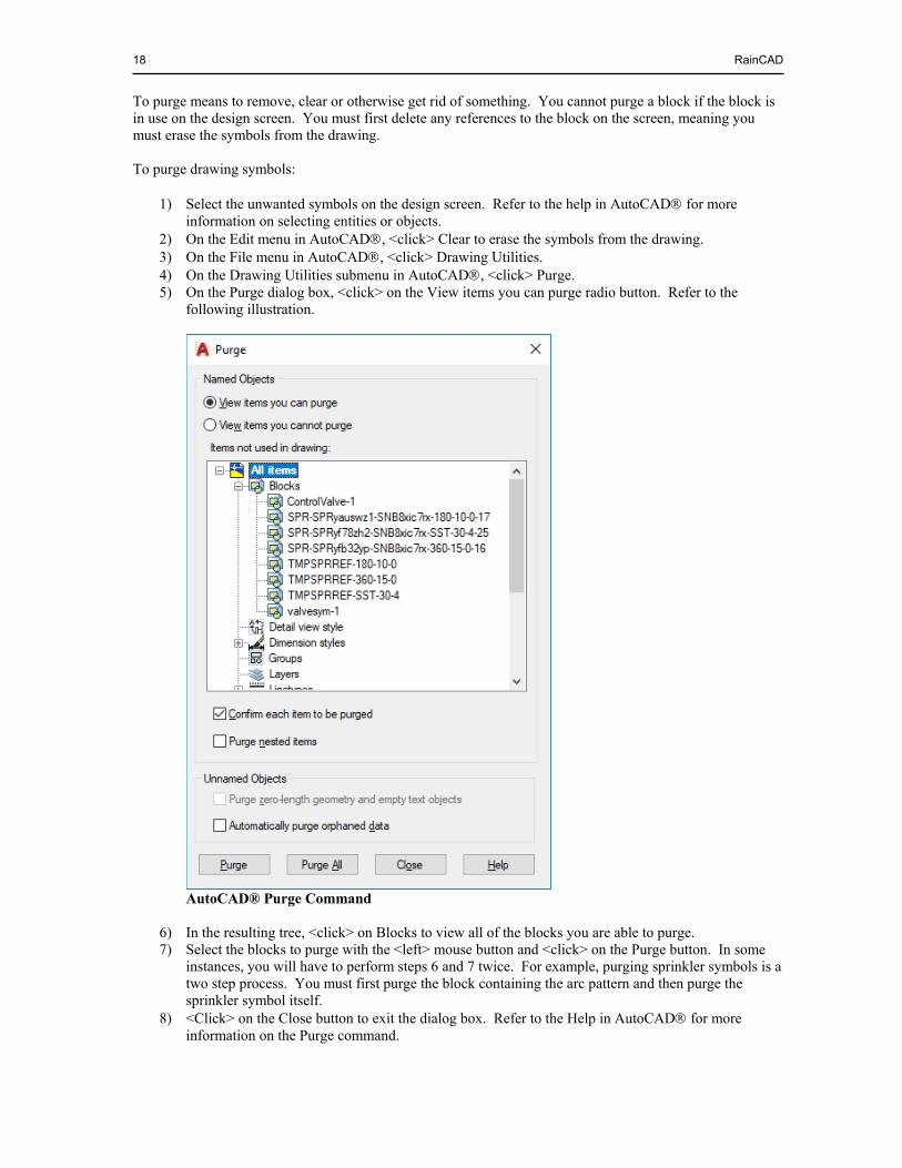
2) On the Edit menu in AutoCAD, <click> Clear to erase the symbols from the drawing. 3) On the File menu in AutoCAD, <click> Drawing Utilities. 4) On the Drawing Utilities submenu in AutoCAD, <click> Purge. 5) On the Purge dialog box, <click> on the View items you can purge radio button. Refer to the
following illustration.
AutoCAD® Purge Command
6) In the resulting tree, <click> on Blocks to view all of the blocks you are able to purge. 7) Select the blocks to purge with the <left> mouse button and <click> on the Purge button. In some
instances, you will have to perform steps 6 and 7 twice. For example, purging sprinkler symbols is a two step process. You must first purge the block containing the arc pattern and then purge the sprinkler symbol itself.
8) <Click> on the Close button to exit the dialog box. Refer to the Help in AutoCAD for more information on the Purge command.
Lesson Two – Settings and Line Styles 19
THE LINE STYLES DATABASE
RainCAD has four preset line styles to represent property lines, driveways, and more. In addition, you may choose from an unlimited number of Custom Line Styles. The characteristics give each line style a different look so that the drawing is more aesthetically appealing and easier to read. You may create a custom line style for landscape design purposes to represent metal edging, landscape timbers, concrete mow curb, cedar fencing, and more. When you draw using these custom line styles, the total length of each line style can be calculated and included in the material list and estimate or proposal. To create or modify the characteristics of a line style:
1) On the RainCAD Databases menu, choose Line Styles. 2) Place the mouse cursor in the tree on the left side of the dialog box and press the <right> mouse
button. 3) <Click> on Add Line Style in the resulting pop-up menu. 4) <Click> on the New Line Style now available at the bottom of the list. 5) Press the <right> mouse button and <click> on Rename. Enter Metal Edging as the new line style
name. 6) Assign the line style to a category from the Category drop down menu. The line style information
will appear in the Legend under this category assignment. For this exercise, select Landscape by <clicking> on the selection one time with the left mouse button.
7) Enter the layer name for the line style in the Layer Name text box. The existing line styles begin with an L-LNST- and then a four character description. For this exercise, enter L-LNST-MEDG in the Layer Name text box.
8) Select the type of line style from the Line Type drop down menu. For this exercise, select a DASHED line by <clicking> on the selection with the mouse. Line types allow you to differentiate between lines drawn on the design screen. You may assign a line to a continuous, dashed, dash dot or one of many other patterns.
9) Select the weight of line style from the Line Weight drop down menu. The line weight refers to the thickness of the line.
10) Select a color for the line style. <Click> on the colored rectangle to the right of the Color label one time with the <left> mouse button to open the Color dialog box. Select a color and <click> on the OK button.
11) To include the line style in the material list and estimate or on the legend, <click> on Show in Material/Estimate and Legend until a checkmark appears in the box.
12) Enter a List Price, Discount Rate, and Labor Rate per linear distance of measurement if you want the Material/Estimate command to calculate the cost of the material.
13) Enter a Part Number in the available text box. 14) <Click> on the Save button to save the line style information. 15) <Click> on the Close button exit the dialog box.
LINE STYLES
The Line Styles command sets the characteristics for all the entities created after the command is selected and a style is chosen. The line style refers to characteristics of a line such as the weight, color, layer assignment, and type (dashed, solid, etc.). You can change the default settings for the line styles in the Line Styles Database. RainCAD presets certain line styles to make it easy for you to create a drawing that will print or plot in presentation quality. The four preset line styles are Property, Driveway, Walkway and Bedlines. You can create additional custom line styles in the Line Styles Database.
NOTE: You may need to experiment with the different line types and widths to determine what settings you like the most.

20 RainCAD
To select a line style: 1) On the RainCAD Symbols menu, choose Line Styles. 2) <Click> one time with the left mouse button on a line style selection. 3) <Click> on the Apply button to change to the preset characteristics. The line style, characteristics,
and color setting will change according to the settings as defined in the Line Styles Database command. All new entities drawn on the design screen will have the characteristics of this line style until another line style is chosen, or the characteristics are changed.
LESSON THREE - DESIGNING THE IRRIGATION SYSTEM PART I
Estimated time to complete: 1 1/2 hours This lesson will cover irrigation commands available in RainCAD. After completing Lesson Three, you should be familiar with:
Boundary lines; how to create them and what they do Placing sprinklers within the drawing screen Adding a water meter or pump station to the drawing screen Grouping sprinklers into zones
RainCAD allows you to approach an irrigation system design in any manner in which you are accustomed. However, there are a few instances where you must follow a preset order. The design approach the tutorial will comply with is as follows:
1) Placing the water meter or pump station 2) Creating the boundary lines 3) Placing the sprinklers 4) Grouping sprinklers into zones 5) Adding the control valve symbols 6) Assigning the control valves to zones 7) Piping the sprinklers 8) Adding the backflow device 9) Drawing the mainline pipe 10) Sizing the pipe 11) Adding other miscellaneous symbols
BEGINNING LESSON THREE - WATER METER AND BOUNDARY LINES
To start Lesson Three -Practice Screen 1: 1) On the RainCAD menu, choose Tutorial. 2) On the Tutorial submenu, choose Lesson 3. 3) In the Lesson 3 category, <click> on Screen 1 and <click> on the Open Tutorial button. Your screen
should look like the following illustration.

22 RainCAD
Lesson Three, Practice Screen Number One You may want to make use of the Zoom command within AutoCAD in the next few steps. This will allow you to get a better view of the front yard while placing the water meter, and the backyard while creating the boundary line.
WATER METER / PUMP STATION
RainCAD refers to each water meter and pump station as a water source. You may have as many water sources on the design as required. When assigning sprinklers or valves to a zone number, you will also need to select the water source that supplies the zone. In this exercise, you will place a water meter on the drawing screen.
1) On the RainCAD Symbols menu, choose Irrigation. 2) On the Irrigation submenu, choose Water Sources. 3) On the Water Source dialog box, <click> on the Add button. A water meter symbol will appear on
your mouse cursor. Follow the Command Line at the bottom of the screen and set a point for the location of the water source symbol by <clicking> one time with the left mouse button.
4) Follow the Command Line again and set a second point to rotate the symbol at the desired angle. For this exercise, set the second point directly to the right of the first point.
5) In the Description text box, enter Residential Meter. You could also adjust the symbol assignment, the symbol color, or assign the water source to a pump station. For this exercise, leave these adjustments set to the default values.
6) In the Meter Information area, select the water meter size from the drop down menu. For this exercise, select a 3/4 inch meter.
NOTE: Do not be concerned if this is not the symbol you want to use to represent the water source. You can adjust the symbol assignment later in the command.
NOTE: RainCAD stores all of the water source information in the symbol. You must place a symbol on the design prior to setting the symbol assignment, water source type, pressure settings, and more. If you assign information to the water source and DO NOT save the drawing, you will lose the water source information. If you erase the symbol from the drawing you will lose the water source information.
Lesson Three - Designing the Irrigation System Part I 23
7) Enter the static pressure available at the water meter. Type in a pressure of 62 pounds per square inch.
8) Enter a difference in elevation from the source to the water meter location of 10.00 feet. Enter a drop in elevation as a negative number and a rise in elevation as a positive number.
9) Enter the Maximum Service Line Velocity in feet per second. Enter a velocity of 5 feet per second for this exercise.
10) Select a pipe category for the supply line from the drop down menu. For this exercise, select Schedule 40.
11) Select the pipe size of 1” from the drop down menu by <clicking> on the selection with the mouse. 12) Enter the service line length of 20.00.
13) <Click> on the Save button to save the water meter information. 14) <Click> on the Close button to close the Water Sources dialog box.
BOUNDARY LINE
A boundary line is a limit or border for automatic sprinkler layout, automatic plant layout, and partial material takeoff calculations. You may place restrictions on a boundary line to prevent sprinklers or spray from sprinklers from entering an area. Now that a water meter exists on the design, it is time to create a boundary line to use when placing sprinklers. Make use of the AutoCAD Zoom command to get a better view of the backyard. To create a boundary line:
1) On the RainCAD Symbols menu, choose Boundary Line. 2) For the purpose of the tutorial, do not place any restrictions on the boundary line. Choose OK to
close the dialog box. 3) Follow the Command Line and set points for the boundary line. Set the points beginning at location
number 1 around to location number 9. You may want to make use of the AutoCAD OSNAP commands for assistance.
NOTE: The program will display the maximum recommended flow of water through the water meter and the available working pressure at the water meter near the bottom of the dialog box. You may change the recommended flow through the water source. <Click> on the Override Recommended Flow box with the left mouse button until a checkmark appears in the box. Enter a new flow in the maximum recommended flow text box.
NOTE: You may have as many boundary lines on the drawing screen as necessary. Boundary lines may overlap other boundary lines or objects on the drawing screen. We do not recommend that you create one boundary line to irrigate an entire project. For example, use separate boundary lines to irrigate the back, front, or sides of a house or building.
NOTE: You can place the water meter information on the design screen by <clicking> on the Insert Info button. Follow the Command Line and set an insertion point for the top left corner of the text. You can edit the text using the AutoCAD Multiline Text Editor.
24 RainCAD
Setting Points for Drawing the Boundary
4) After setting point number 9, press <Enter> to end the line. RainCAD will automatically close the
boundary line by connecting the first point with the last point.
SPRINKLER PLACEMENT – WITHIN A BOUNDARY
You can place sprinkler symbols on the drawing screen either manually or with one of several different automatic placement features. Using the automatic features, you can place symbols along an existing or temporary polyline, or within a boundary line. In this exercise, you will place the sprinklers automatically using the boundary line you just created. To begin placing sprinkler symbols within the boundary line:
1) On the RainCAD Symbols menu, choose Irrigation. 2) On the Irrigation submenu, choose Sprinklers. 3) On the Sprinkler Placement dialog box, <click> on the Within a Boundary tab. 4) Double <click> on a Manufacturer with the left mouse button or single <click> on the + sign to the
left of the manufacturers name to view the available sprinkler nozzle categories. For this lesson, <click> on Rain Bird in the list of manufacturers.
5) Double <click> on a Category Name with the left mouse button or single <click> on the + sign to the left of the category name to view the available sprinkler palettes. Select Turf Sprays from the list of Category Names.
6) <Click> on a Palette Name one time with the left mouse button to view a list of the sprinklers assigned to the palette. For this lesson, <click> on 15’s.
NOTE: A palette is the assortment of sprinklers RainCAD will use to fill the boundary line. You must have a 180 degree and a 360 degree arc pattern assigned to each palette. Palettes are created in the Sprinklers Database on the Palette Assignment tab in RainCAD.
NOTE: Do not attempt to close the boundary line on your own. Set your last point short of the beginning point and press <Enter> on the keyboard to allow RainCAD to automatically close the boundary line.
Lesson Three - Designing the Irrigation System Part I 25
7) Leave the Sprinkler Body Assignment set to Use from Database. Select Square spacing from the Desired Sprinkler Layout drop down menu. Select % of Diameter from the Desired Sprinkler Spacing drop down menu and enter 50 in the % of Diameter text box. Enter 10 in the % of Overspray Allowed box and 0.50 in the Sprinkler Offset Along Boundary Line box. Leave the Automatic Radius Reduction checkbox disabled. Refer to the RainCAD help screens for more information on these options.
8) <Click> on the OK button and follow Command Line at the bottom of the screen. 9) <Click> one time on the boundary line with the left mouse button to select the object.
10) If the Automatically Calculate Full Circle Row Angle checkbox is disabled, continue to follow the
Command Line at the bottom of the screen and set two points on the screen for the row angle of all full circle sprinklers filling the center of the boundary area.
11) The sprinkler symbols will automatically be placed within the boundary line area.
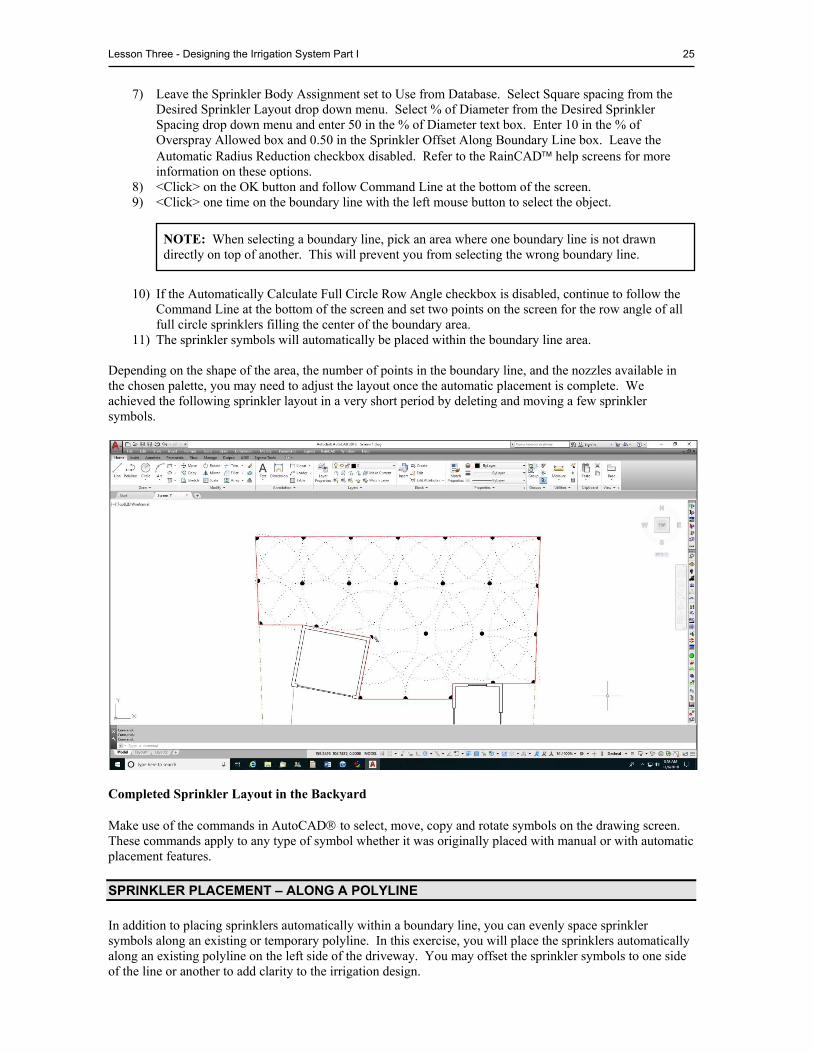
Depending on the shape of the area, the number of points in the boundary line, and the nozzles available in the chosen palette, you may need to adjust the layout once the automatic placement is complete. We achieved the following sprinkler layout in a very short period by deleting and moving a few sprinkler symbols.
Completed Sprinkler Layout in the Backyard Make use of the commands in AutoCAD to select, move, copy and rotate symbols on the drawing screen. These commands apply to any type of symbol whether it was originally placed with manual or with automatic placement features.
SPRINKLER PLACEMENT – ALONG A POLYLINE
In addition to placing sprinklers automatically within a boundary line, you can evenly space sprinkler symbols along an existing or temporary polyline. In this exercise, you will place the sprinklers automatically along an existing polyline on the left side of the driveway. You may offset the sprinkler symbols to one side of the line or another to add clarity to the irrigation design.
NOTE: When selecting a boundary line, pick an area where one boundary line is not drawn directly on top of another. This will prevent you from selecting the wrong boundary line.
26 RainCAD
Before placing the sprinklers, use the commands available in AutoCAD to zoom out so you can see the entire driveway. To begin placing sprinkler symbols along a polyline:
1) On the RainCAD Symbols menu, choose Irrigation. 2) On the Irrigation submenu, choose Sprinklers. 3) On the Sprinkler Placement dialog box, <click> on the Along a Polyline tab. 4) Double <click> on a Manufacturer with the left mouse button or single <click> on the + sign to the
left of the manufacturers name to view the available sprinkler nozzle categories. For this lesson, <click> on Rain Bird in the list of manufacturers.
5) Double <click> on a Category Name with the left mouse button or single <click> on the + sign to the left of the category name to view the available sprinkler nozzles. Select Turf Sprays from the list of Category Names.
6) <Click> one time with the left mouse button on the desired sprinkler nozzle. Select a 10H from the list of available sprinkler nozzles.
7) To place the selected sprinkler nozzle automatically along an existing polyline on the drawing screen, <click> on the Along an Existing Polyline radio button. Enter 0.50 in the Sprinkler Polyline Offset text box and click on the OK button.
8) Follow the Command Line at the bottom of the screen and select the polyline to use in sprinkler placement. <Click> one time on the left driveway line running from the street to the garage.
9) Continue to follow the Command Line at the bottom of the screen. Set a point on the side of the line on which the symbols will be placed. <Click> one time to the left of the line so that the sprinklers will face away from the driveway.
10) The actual length of the polyline as well as the calculated spacing of the symbols will be displayed in the resulting dialog box. Leave the desired spacing for the sprinkler symbols set to 10 feet in the Desired Spacing text box.
11) <Click> on the OK button to place the sprinklers automatically along the polyline.
MANUAL SPRINKLER PLACEMENT
Manually placing sprinklers is a simple process. Simply select a sprinkler nozzle, set a point for its location, and then set another point in the direction the nozzle will face. It may be necessary to zoom in on the area in which you will be working. Before you begin placing sprinklers manually, zoom in on the bottom left corner of the property so you can see the driveway and property lines. To begin manually placing sprinkler symbols:
1) On the RainCAD Symbols menu, choose Irrigation. 2) On the Irrigation submenu, choose Sprinklers. 3) On the Sprinkler Placement dialog box, <click> on the Manual Placement tab. 4) Double <click> on a Manufacturer with the left mouse button or single <click> on the + sign to the
left of the manufacturers name to view the available sprinkler nozzle categories. For this lesson, <click> on Rain Bird in the list of manufacturers.
5) Double <click> on a Category Name with the left mouse button or single <click> on the + sign to the left of the category name to view the available sprinkler nozzles. Select Turf Sprays from the list of Category Names.
NOTE: To space the sprinkler symbols evenly along the polyline, select Even Spacing from the Spacing Type drop down menu. To space the symbols at the exact spacing entered in the Desired Spacing text box, select Exact Spacing in the drop down menu.
NOTE: If the Sprinkler Polyline Offset is set to zero (0), the sprinklers will appear directly on top of the polyline.
Lesson Three - Designing the Irrigation System Part I 27
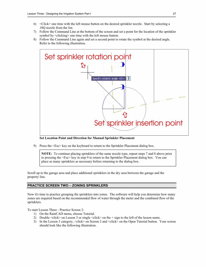
6) <Click> one time with the left mouse button on the desired sprinkler nozzle. Start by selecting a 10Q nozzle from the list.
7) Follow the Command Line at the bottom of the screen and set a point for the location of the sprinkler symbol by <clicking> one time with the left mouse button.
8) Follow the Command Line again and set a second point to rotate the symbol at the desired angle. Refer to the following illustration.
Set Location Point and Direction for Manual Sprinkler Placement
9) Press the <Esc> key on the keyboard to return to the Sprinkler Placement dialog box.
Scroll up to the garage area and place additional sprinklers in the dry area between the garage and the property line.
PRACTICE SCREEN TWO – ZONING SPRINKLERS
Now it's time to practice grouping the sprinklers into zones. The software will help you determine how many zones are required based on the recommended flow of water through the meter and the combined flow of the sprinklers. To start Lesson Three - Practice Screen 2:
1) On the RainCAD menu, choose Tutorial. 2) Double <click> on Lesson 3 or single <click> on the + sign to the left of the lesson name. 3) In the Lesson 3 category, <click> on Screen 2 and <click> on the Open Tutorial button. Your screen
should look like the following illustration.
NOTE: To continue placing sprinklers of the same nozzle type, repeat steps 7 and 8 above prior to pressing the <Esc> key in step 9 to return to the Sprinkler Placement dialog box. You can place as many sprinklers as necessary before returning to the dialog box.
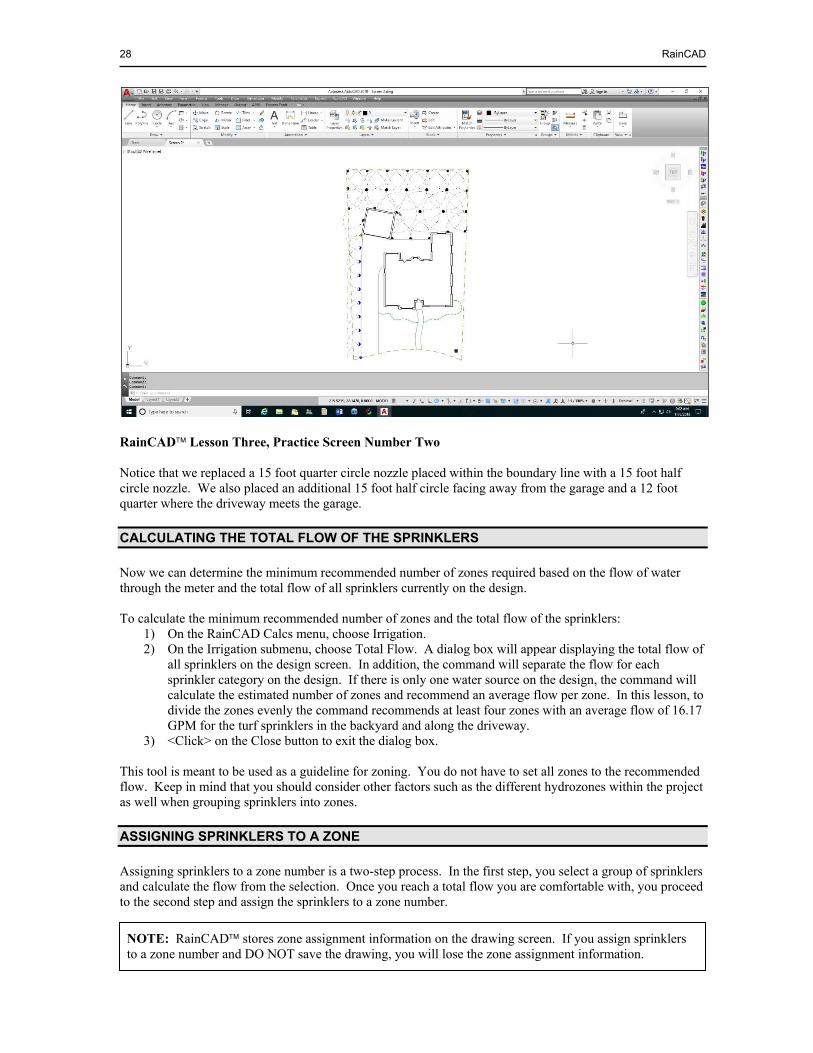
28 RainCAD
RainCAD Lesson Three, Practice Screen Number Two Notice that we replaced a 15 foot quarter circle nozzle placed within the boundary line with a 15 foot half circle nozzle. We also placed an additional 15 foot half circle facing away from the garage and a 12 foot quarter where the driveway meets the garage.
CALCULATING THE TOTAL FLOW OF THE SPRINKLERS
Now we can determine the minimum recommended number of zones required based on the flow of water through the meter and the total flow of all sprinklers currently on the design. To calculate the minimum recommended number of zones and the total flow of the sprinklers:
1) On the RainCAD Calcs menu, choose Irrigation. 2) On the Irrigation submenu, choose Total Flow. A dialog box will appear displaying the total flow of
all sprinklers on the design screen. In addition, the command will separate the flow for each sprinkler category on the design. If there is only one water source on the design, the command will calculate the estimated number of zones and recommend an average flow per zone. In this lesson, to divide the zones evenly the command recommends at least four zones with an average flow of 16.17 GPM for the turf sprinklers in the backyard and along the driveway.
3) <Click> on the Close button to exit the dialog box. This tool is meant to be used as a guideline for zoning. You do not have to set all zones to the recommended flow. Keep in mind that you should consider other factors such as the different hydrozones within the project as well when grouping sprinklers into zones.
ASSIGNING SPRINKLERS TO A ZONE
Assigning sprinklers to a zone number is a two-step process. In the first step, you select a group of sprinklers and calculate the flow from the selection. Once you reach a total flow you are comfortable with, you proceed to the second step and assign the sprinklers to a zone number.
NOTE: RainCAD stores zone assignment information on the drawing screen. If you assign sprinklers to a zone number and DO NOT save the drawing, you will lose the zone assignment information.
Lesson Three - Designing the Irrigation System Part I 29
To select a group of sprinklers and calculate their flow: 1) On the RainCAD Calcs menu, choose Irrigation. 2) On the Irrigation submenu, choose Water Source/Zone Assignment. 3) On the Water Source/Zone Assignment dialog box, <click> on the Assignment tab. 4) Each design may have more than one water source. Before you may assign sprinklers or control
valves to a zone number, you must first select the water source supplying the zone. In the Water Source Assignment location, <click> on the down arrow to view a list of the available water sources. In this lesson, you will only have one water source in the list. <Click> on the water source name one time with the mouse.
5) Select the row across the back of the property line with five half circle and two quarter circle sprinklers. Refer to the help in AutoCAD for assistance in selecting entities on the design screen.
6) <Click> on the Get Flow From Selection button to determine the flow of the selected sprinklers. You should have seven sprinklers selected with a flow of 11.09 GPM. This is below the recommended flow, so add a few more sprinklers to the zone.
7) <Click> on the half circle sprinkler against the property line on the left side of the backyard and the full circle sprinkler just to its right.
8) <Click> on the Get Flow From Selection button again to determine the flow of the selected
sprinklers. You should now have nine sprinklers selected with a flow of 16.64 GPM. The flow of the selected sprinklers is slightly higher than the recommended flow of each zone, but less than the capability of the water source. We will proceed to assign these sprinklers to zone number one. You can add or remove sprinklers to or from a zone at any time. To assign the sprinklers to a zone number:
1) In the Zone Number Assignment text box, type in the number <1> for the zone assignment, or <click> on the left or right arrow buttons to decrease or increase the zone assignment number. There is no limit to the number of zones you may have per water source.
2) In the Assignment Type location, <click> on Add Selection to Zone and then <click> on the Apply button. A 1-1 will appear next to the sprinkler symbols indicating that they are assigned to water source number one and zone number one.
3) <Click> on the AutoCAD screen to make it the current application. 4) Press the <Esc> key one time to “unselect” the sprinkler symbols on the design screen. 5) Following the steps above, select the next row of four full circle sprinklers and one half circle
sprinkler and assign them to zone number two. 6) Select the remaining ten sprinklers in the backyard area including the 15 foot half circle directly
behind the garage and assign them to zone number three. Be sure to press the <Esc> to unselect the sprinklers just assigned to zone number two before you begin selecting sprinklers for zone three.
7) Select the remaining twelve sprinklers to the left of the garage and driveway and assign them to zone
number four.
NOTE: When the flow exceeds the recommended flow through the water source, the associated labels turn red as an indicator in the Water Source/Zone Assignment dialog box. This is strictly an indicator; the program will not stop the designer from assigning more flow to a zone than the recommendation.
NOTE: It may be easier to select sprinklers by <clicking> on the arc pattern versus selecting the sprinkler symbol itself.
NOTE: To remove sprinklers or control valves from a zone assignment, select the symbols, <click> on Remove Selection from Zone in the Assignment Type location, and then <click> on the Apply button.
30 RainCAD
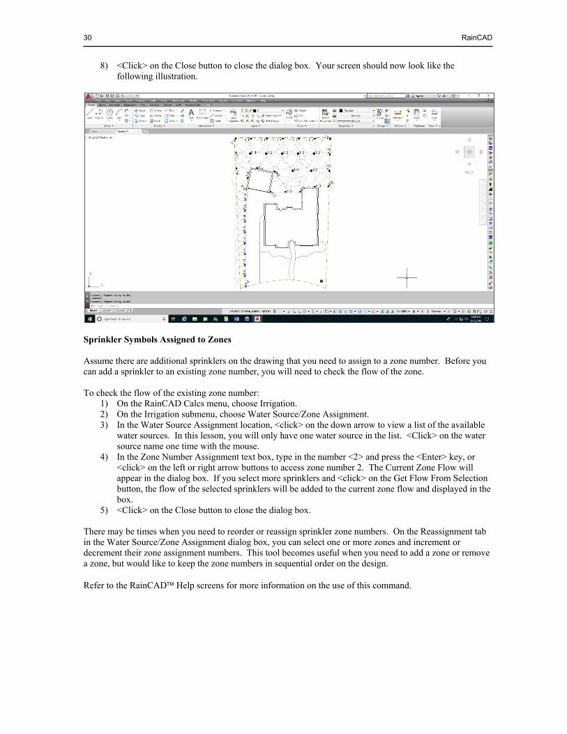
8) <Click> on the Close button to close the dialog box. Your screen should now look like the following illustration.
Sprinkler Symbols Assigned to Zones Assume there are additional sprinklers on the drawing that you need to assign to a zone number. Before you can add a sprinkler to an existing zone number, you will need to check the flow of the zone. To check the flow of the existing zone number:
1) On the RainCAD Calcs menu, choose Irrigation. 2) On the Irrigation submenu, choose Water Source/Zone Assignment. 3) In the Water Source Assignment location, <click> on the down arrow to view a list of the available
water sources. In this lesson, you will only have one water source in the list. <Click> on the water source name one time with the mouse.
4) In the Zone Number Assignment text box, type in the number <2> and press the <Enter> key, or <click> on the left or right arrow buttons to access zone number 2. The Current Zone Flow will appear in the dialog box. If you select more sprinklers and <click> on the Get Flow From Selection button, the flow of the selected sprinklers will be added to the current zone flow and displayed in the box.
5) <Click> on the Close button to close the dialog box. There may be times when you need to reorder or reassign sprinkler zone numbers. On the Reassignment tab in the Water Source/Zone Assignment dialog box, you can select one or more zones and increment or decrement their zone assignment numbers. This tool becomes useful when you need to add a zone or remove a zone, but would like to keep the zone numbers in sequential order on the design. Refer to the RainCAD Help screens for more information on the use of this command.
LESSON FOUR - DESIGNING THE IRRIGATION SYSTEM PART II
Estimated time to complete: 2 hours Having completed the first few lessons, you should have a better understanding of how to place sprinkler symbols and assign them to zones. Now you will learn how to add control valves, assign control valves to a zone number, pipe the lateral zones, draw the mainline pipe and more. After completing Lesson Four, you should be able to:
Place irrigation control valve symbols Assign control valves to a zone Draw lateral line pipe Create pipe “hops” Place backflow prevention devices Draw mainline pipe
BEGINNING LESSON FOUR – UNDERSTANDING LAYERS
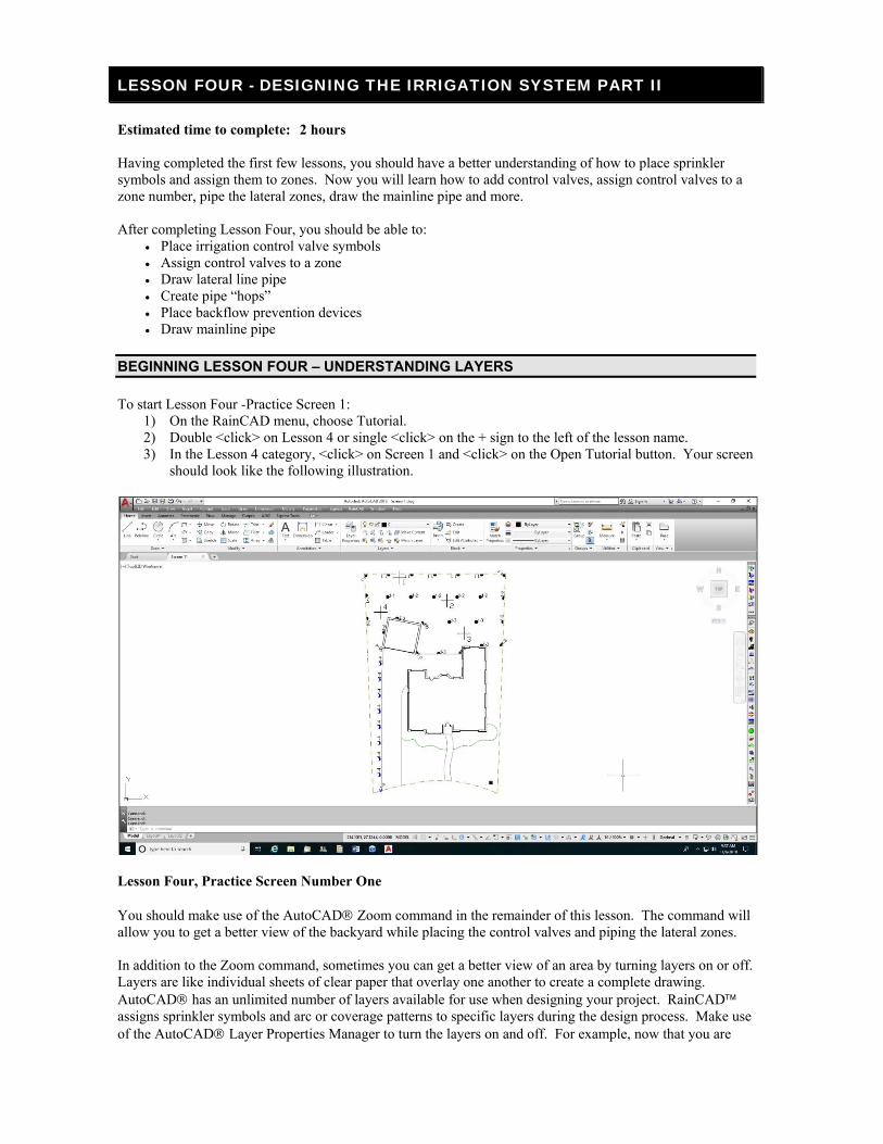
To start Lesson Four -Practice Screen 1: 1) On the RainCAD menu, choose Tutorial. 2) Double <click> on Lesson 4 or single <click> on the + sign to the left of the lesson name. 3) In the Lesson 4 category, <click> on Screen 1 and <click> on the Open Tutorial button. Your screen
should look like the following illustration.
Lesson Four, Practice Screen Number One You should make use of the AutoCAD Zoom command in the remainder of this lesson. The command will allow you to get a better view of the backyard while placing the control valves and piping the lateral zones. In addition to the Zoom command, sometimes you can get a better view of an area by turning layers on or off. Layers are like individual sheets of clear paper that overlay one another to create a complete drawing. AutoCAD has an unlimited number of layers available for use when designing your project. RainCAD assigns sprinkler symbols and arc or coverage patterns to specific layers during the design process. Make use of the AutoCAD Layer Properties Manager to turn the layers on and off. For example, now that you are
32 RainCAD
through placing sprinklers in the backyard, it may be beneficial to turn the sprinkler arc or coverage patterns off while placing the control valves and lateral line pipe. To turn the sprinkler arc patterns off:
1) Enact the AutoCAD Layer Properties Manager. 2) Scroll down until you see the layer named L-SPRI-TSPR-COVG.
3) <Click> one time on the light bulb icon to turn the sprinkler arc or coverage pattern layer for turf spray nozzles off.
4) <Click> on the OK button to close the dialog box. For additional information on layers, refer to the AutoCAD help screens or reference manual.
PLACING CONTROL VALVES
RainCAD will automatically pipe the sprinklers assigned to a lateral zone. For the software to pipe the lateral zones, you must place the irrigation control valves on the drawing screen and assign them to a zone number. You may place control valves anywhere on the drawing screen. If necessary, make use of the AutoCAD Zoom command before placing the control valve symbols. To place irrigation control valve symbols:
1) On the RainCAD Symbols menu, choose Irrigation. 2) On the Irrigation submenu, choose Control Valves. 3) Double <click> on a Manufacturer with the left mouse button or single <click> on the + sign to the
left of the manufacturers name to view the available control valves. For this lesson, <click> on Hunter in the list of manufacturers.
4) <Click> one time with the left mouse button on a PGV-101G and <click> on the OK button to place the symbol on the drawing screen.
5) Follow the Command Line at the bottom of the screen and set a point for the location of the symbol by <clicking> one time with the left mouse button. For this exercise, <click> on the point mark to the left of the 1 indicator in the backyard.
6) Follow the Command Line again and set a second point to rotate the symbol at the desired angle. 7) Repeat steps 5 and 6 above to continue placing control valves on the point marks next to indicators
2, 3, and 4. 8) Once the control valves are placed, press the <Esc> key on the keyboard to return to the dialog box. 9) <Click> on the Close button to close the dialog box.
PRACTICE SCREEN TWO – CONTROL VALVE ZONE ASSIGNMENTS
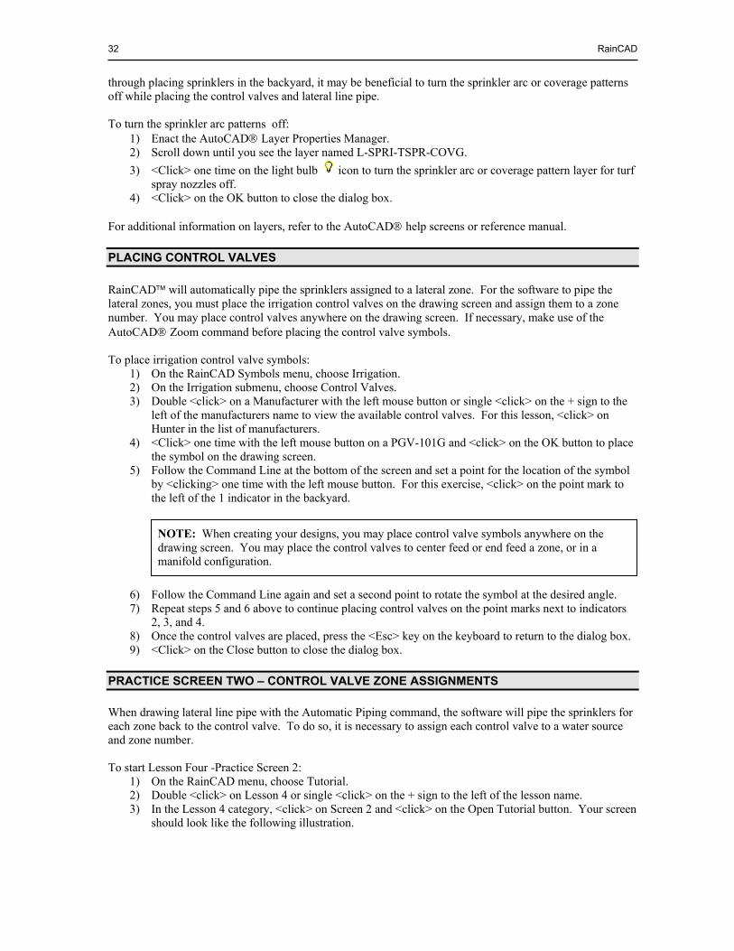
When drawing lateral line pipe with the Automatic Piping command, the software will pipe the sprinklers for each zone back to the control valve. To do so, it is necessary to assign each control valve to a water source and zone number. To start Lesson Four -Practice Screen 2:
1) On the RainCAD menu, choose Tutorial. 2) Double <click> on Lesson 4 or single <click> on the + sign to the left of the lesson name. 3) In the Lesson 4 category, <click> on Screen 2 and <click> on the Open Tutorial button. Your screen
should look like the following illustration.
NOTE: When creating your designs, you may place control valve symbols anywhere on the drawing screen. You may place the control valves to center feed or end feed a zone, or in a manifold configuration.
Lesson Four - Designing the Irrigation System Part II 33
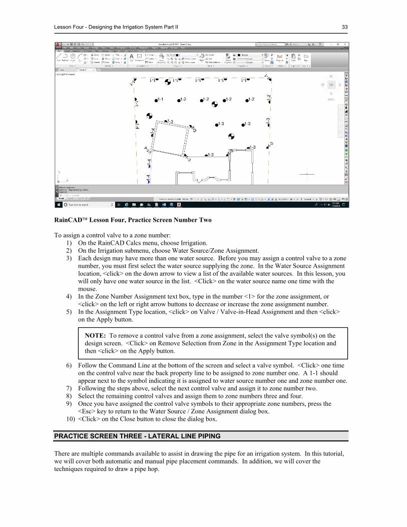
RainCAD Lesson Four, Practice Screen Number Two To assign a control valve to a zone number:
1) On the RainCAD Calcs menu, choose Irrigation. 2) On the Irrigation submenu, choose Water Source/Zone Assignment. 3) Each design may have more than one water source. Before you may assign a control valve to a zone
number, you must first select the water source supplying the zone. In the Water Source Assignment location, <click> on the down arrow to view a list of the available water sources. In this lesson, you will only have one water source in the list. <Click> on the water source name one time with the mouse.
4) In the Zone Number Assignment text box, type in the number <1> for the zone assignment, or <click> on the left or right arrow buttons to decrease or increase the zone assignment number.
5) In the Assignment Type location, <click> on Valve / Valve-in-Head Assignment and then <click> on the Apply button.
6) Follow the Command Line at the bottom of the screen and select a valve symbol. <Click> one time
on the control valve near the back property line to be assigned to zone number one. A 1-1 should appear next to the symbol indicating it is assigned to water source number one and zone number one.
7) Following the steps above, select the next control valve and assign it to zone number two. 8) Select the remaining control valves and assign them to zone numbers three and four. 9) Once you have assigned the control valve symbols to their appropriate zone numbers, press the
<Esc> key to return to the Water Source / Zone Assignment dialog box. 10) <Click> on the Close button to close the dialog box.
PRACTICE SCREEN THREE - LATERAL LINE PIPING
There are multiple commands available to assist in drawing the pipe for an irrigation system. In this tutorial, we will cover both automatic and manual pipe placement commands. In addition, we will cover the techniques required to draw a pipe hop.
NOTE: To remove a control valve from a zone assignment, select the valve symbol(s) on the design screen. <Click> on Remove Selection from Zone in the Assignment Type location and then <click> on the Apply button.

34 RainCAD
We will begin with the Automatic Piping command. For this command to function properly, you must assign the sprinkler symbols and control valves to a zone number. For more information on zone assignments, refer to Assigning Sprinklers to a Zone and Control Valve Zone Assignments previously covered in this manual. To begin automatic piping of the sprinkler zones:
1) On the RainCAD menu, choose Tutorial. 2) Double <click> on Lesson 4 or single <click> on the + sign to the left of the lesson name. 3) In the Lesson 4 category, <click> on Screen 3 and <click> on the Open Tutorial button. Your screen
should look like the following illustration.
Lesson Four, Practice Screen Number Three The sprinklers and control valves on the screen represent those placed on the drawing in previous exercises. You know which sprinklers to pipe together based on their water source and zone assignment numbers. Before placing the pipe, use the AutoCAD Layer Properties Manager to turn off the sprinkler arc patterns. Now it's time to begin drawing lateral line pipe. To use the Automatic Piping command:
1) On the RainCAD Symbols menu, choose Irrigation. 2) On the Irrigation submenu, choose Pipe Placement. 3) On the Pipe Placement dialog box, <click> on the Automatic Piping tab. 4) Select each sprinkler zone to pipe in the Check Zones for Automatic Lateral Line Piping box.
<Click> on each selection with the left mouse button until a checkmark appears in the box. Select zones 1, 2 and 3 since the sprinklers in each zone basically form horizontal rows.
NOTE: You do not have to pipe all zones at one time. You can pipe each zone individually and adjust the settings as required to achieve the desired piping results. To pipe all lateral line zones at one time, <click> on All Zones until a checkmark appears in the box.
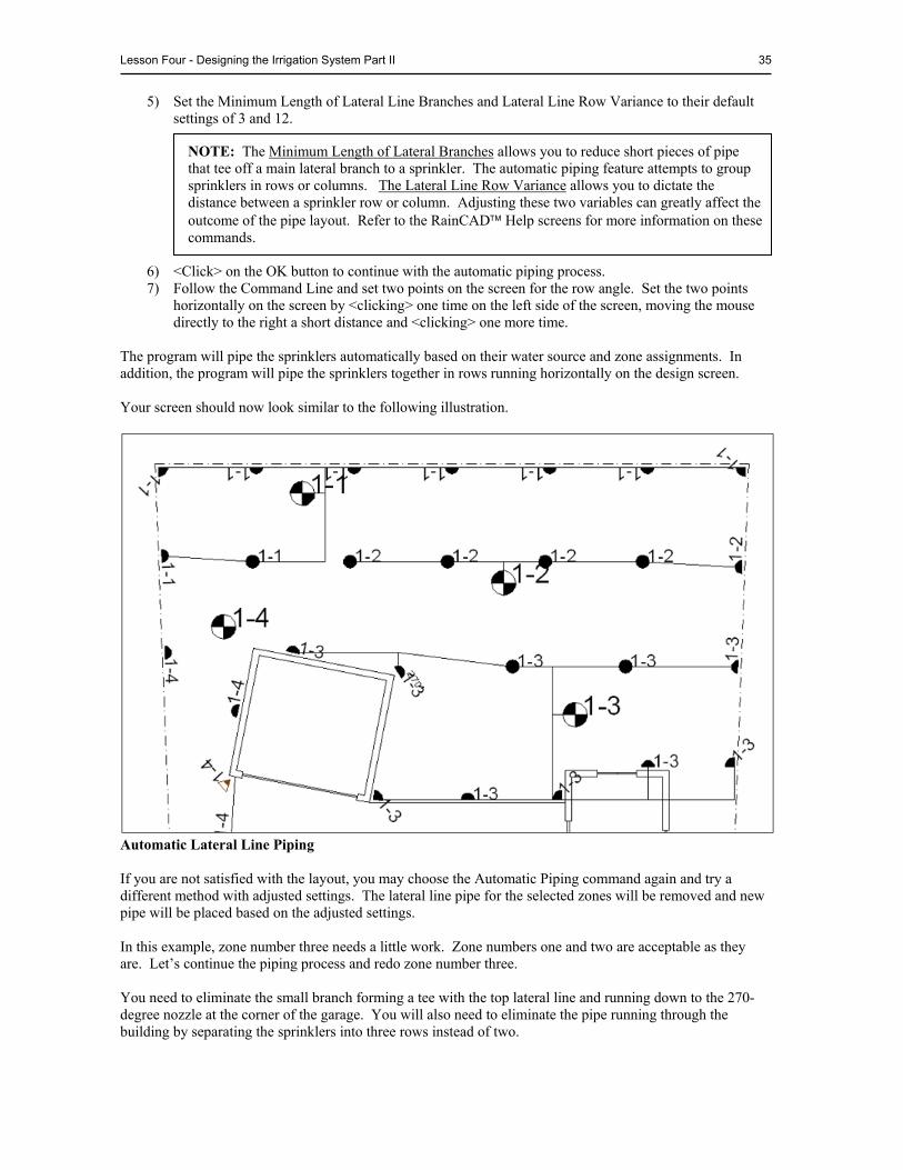
Lesson Four - Designing the Irrigation System Part II 35
5) Set the Minimum Length of Lateral Line Branches and Lateral Line Row Variance to their default settings of 3 and 12.
6) <Click> on the OK button to continue with the automatic piping process. 7) Follow the Command Line and set two points on the screen for the row angle. Set the two points
horizontally on the screen by <clicking> one time on the left side of the screen, moving the mouse directly to the right a short distance and <clicking> one more time.
The program will pipe the sprinklers automatically based on their water source and zone assignments. In addition, the program will pipe the sprinklers together in rows running horizontally on the design screen. Your screen should now look similar to the following illustration.
Automatic Lateral Line Piping If you are not satisfied with the layout, you may choose the Automatic Piping command again and try a different method with adjusted settings. The lateral line pipe for the selected zones will be removed and new pipe will be placed based on the adjusted settings. In this example, zone number three needs a little work. Zone numbers one and two are acceptable as they are. Let’s continue the piping process and redo zone number three. You need to eliminate the small branch forming a tee with the top lateral line and running down to the 270-degree nozzle at the corner of the garage. You will also need to eliminate the pipe running through the building by separating the sprinklers into three rows instead of two.
NOTE: The Minimum Length of Lateral Branches allows you to reduce short pieces of pipe that tee off a main lateral branch to a sprinkler. The automatic piping feature attempts to group sprinklers in rows or columns. The Lateral Line Row Variance allows you to dictate the distance between a sprinkler row or column. Adjusting these two variables can greatly affect the outcome of the pipe layout. Refer to the RainCAD Help screens for more information on these commands.
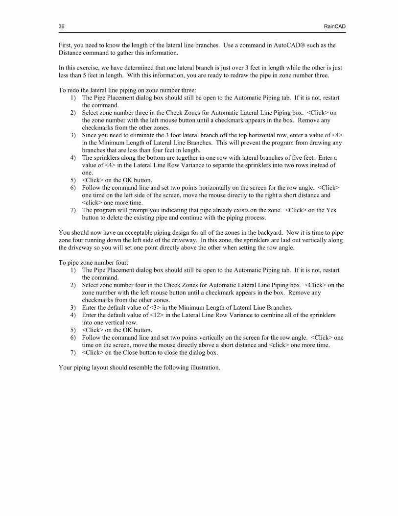
36 RainCAD
First, you need to know the length of the lateral line branches. Use a command in AutoCAD such as the Distance command to gather this information. In this exercise, we have determined that one lateral branch is just over 3 feet in length while the other is just less than 5 feet in length. With this information, you are ready to redraw the pipe in zone number three. To redo the lateral line piping on zone number three:
1) The Pipe Placement dialog box should still be open to the Automatic Piping tab. If it is not, restart the command.
2) Select zone number three in the Check Zones for Automatic Lateral Line Piping box. <Click> on the zone number with the left mouse button until a checkmark appears in the box. Remove any checkmarks from the other zones.
3) Since you need to eliminate the 3 foot lateral branch off the top horizontal row, enter a value of <4> in the Minimum Length of Lateral Line Branches. This will prevent the program from drawing any branches that are less than four feet in length.
4) The sprinklers along the bottom are together in one row with lateral branches of five feet. Enter a value of <4> in the Lateral Line Row Variance to separate the sprinklers into two rows instead of one.
5) <Click> on the OK button. 6) Follow the command line and set two points horizontally on the screen for the row angle. <Click>
one time on the left side of the screen, move the mouse directly to the right a short distance and <click> one more time.
7) The program will prompt you indicating that pipe already exists on the zone. <Click> on the Yes button to delete the existing pipe and continue with the piping process.
You should now have an acceptable piping design for all of the zones in the backyard. Now it is time to pipe zone four running down the left side of the driveway. In this zone, the sprinklers are laid out vertically along the driveway so you will set one point directly above the other when setting the row angle. To pipe zone number four:
1) The Pipe Placement dialog box should still be open to the Automatic Piping tab. If it is not, restart the command.
2) Select zone number four in the Check Zones for Automatic Lateral Line Piping box. <Click> on the zone number with the left mouse button until a checkmark appears in the box. Remove any checkmarks from the other zones.
3) Enter the default value of <3> in the Minimum Length of Lateral Line Branches. 4) Enter the default value of <12> in the Lateral Line Row Variance to combine all of the sprinklers
into one vertical row. 5) <Click> on the OK button. 6) Follow the command line and set two points vertically on the screen for the row angle. <Click> one
time on the screen, move the mouse directly above a short distance and <click> one more time. 7) <Click> on the Close button to close the dialog box.
Your piping layout should resemble the following illustration.
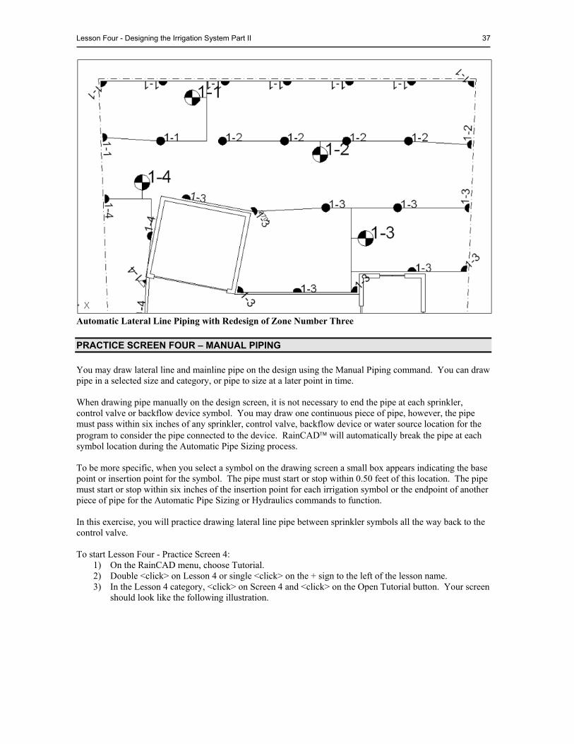
Lesson Four - Designing the Irrigation System Part II 37
Automatic Lateral Line Piping with Redesign of Zone Number Three
PRACTICE SCREEN FOUR – MANUAL PIPING
You may draw lateral line and mainline pipe on the design using the Manual Piping command. You can draw pipe in a selected size and category, or pipe to size at a later point in time. When drawing pipe manually on the design screen, it is not necessary to end the pipe at each sprinkler, control valve or backflow device symbol. You may draw one continuous piece of pipe, however, the pipe must pass within six inches of any sprinkler, control valve, backflow device or water source location for the program to consider the pipe connected to the device. RainCAD will automatically break the pipe at each symbol location during the Automatic Pipe Sizing process. To be more specific, when you select a symbol on the drawing screen a small box appears indicating the base point or insertion point for the symbol. The pipe must start or stop within 0.50 feet of this location. The pipe must start or stop within six inches of the insertion point for each irrigation symbol or the endpoint of another piece of pipe for the Automatic Pipe Sizing or Hydraulics commands to function. In this exercise, you will practice drawing lateral line pipe between sprinkler symbols all the way back to the control valve. To start Lesson Four - Practice Screen 4:
1) On the RainCAD menu, choose Tutorial. 2) Double <click> on Lesson 4 or single <click> on the + sign to the left of the lesson name. 3) In the Lesson 4 category, <click> on Screen 4 and <click> on the Open Tutorial button. Your screen
should look like the following illustration.
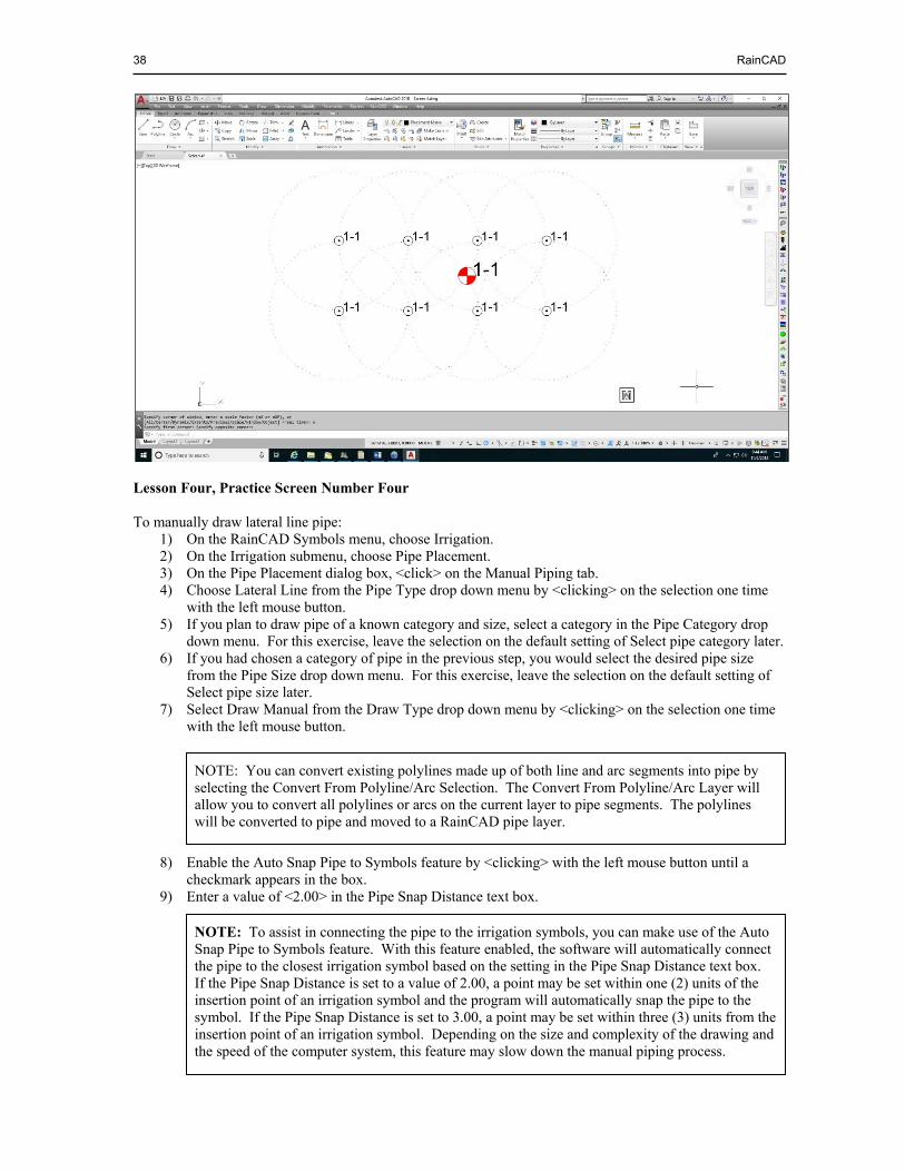
38 RainCAD
Lesson Four, Practice Screen Number Four To manually draw lateral line pipe:
1) On the RainCAD Symbols menu, choose Irrigation. 2) On the Irrigation submenu, choose Pipe Placement. 3) On the Pipe Placement dialog box, <click> on the Manual Piping tab. 4) Choose Lateral Line from the Pipe Type drop down menu by <clicking> on the selection one time
with the left mouse button. 5) If you plan to draw pipe of a known category and size, select a category in the Pipe Category drop
down menu. For this exercise, leave the selection on the default setting of Select pipe category later. 6) If you had chosen a category of pipe in the previous step, you would select the desired pipe size
from the Pipe Size drop down menu. For this exercise, leave the selection on the default setting of Select pipe size later.
7) Select Draw Manual from the Draw Type drop down menu by <clicking> on the selection one time with the left mouse button.
8) Enable the Auto Snap Pipe to Symbols feature by <clicking> with the left mouse button until a checkmark appears in the box.
9) Enter a value of <2.00> in the Pipe Snap Distance text box.
NOTE: To assist in connecting the pipe to the irrigation symbols, you can make use of the Auto Snap Pipe to Symbols feature. With this feature enabled, the software will automatically connect the pipe to the closest irrigation symbol based on the setting in the Pipe Snap Distance text box. If the Pipe Snap Distance is set to a value of 2.00, a point may be set within one (2) units of the insertion point of an irrigation symbol and the program will automatically snap the pipe to the symbol. If the Pipe Snap Distance is set to 3.00, a point may be set within three (3) units from the insertion point of an irrigation symbol. Depending on the size and complexity of the drawing and the speed of the computer system, this feature may slow down the manual piping process.
NOTE: You can convert existing polylines made up of both line and arc segments into pipe by selecting the Convert From Polyline/Arc Selection. The Convert From Polyline/Arc Layer will allow you to convert all polylines or arcs on the current layer to pipe segments. The polylines will be converted to pipe and moved to a RainCAD pipe layer.
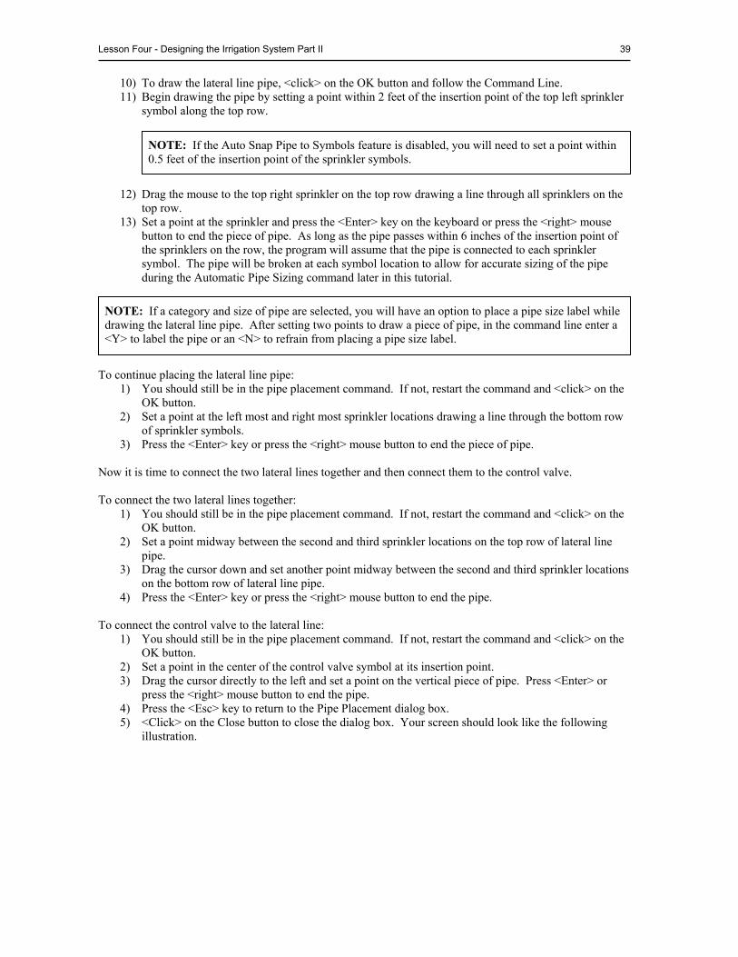
Lesson Four - Designing the Irrigation System Part II 39
10) To draw the lateral line pipe, <click> on the OK button and follow the Command Line. 11) Begin drawing the pipe by setting a point within 2 feet of the insertion point of the top left sprinkler
symbol along the top row.
12) Drag the mouse to the top right sprinkler on the top row drawing a line through all sprinklers on the top row.
13) Set a point at the sprinkler and press the <Enter> key on the keyboard or press the <right> mouse button to end the piece of pipe. As long as the pipe passes within 6 inches of the insertion point of the sprinklers on the row, the program will assume that the pipe is connected to each sprinkler symbol. The pipe will be broken at each symbol location to allow for accurate sizing of the pipe during the Automatic Pipe Sizing command later in this tutorial.
To continue placing the lateral line pipe:
1) You should still be in the pipe placement command. If not, restart the command and <click> on the OK button.
2) Set a point at the left most and right most sprinkler locations drawing a line through the bottom row of sprinkler symbols.
3) Press the <Enter> key or press the <right> mouse button to end the piece of pipe. Now it is time to connect the two lateral lines together and then connect them to the control valve. To connect the two lateral lines together:
1) You should still be in the pipe placement command. If not, restart the command and <click> on the OK button.
2) Set a point midway between the second and third sprinkler locations on the top row of lateral line pipe.
3) Drag the cursor down and set another point midway between the second and third sprinkler locations on the bottom row of lateral line pipe.
4) Press the <Enter> key or press the <right> mouse button to end the pipe. To connect the control valve to the lateral line:
1) You should still be in the pipe placement command. If not, restart the command and <click> on the OK button.
2) Set a point in the center of the control valve symbol at its insertion point. 3) Drag the cursor directly to the left and set a point on the vertical piece of pipe. Press <Enter> or
press the <right> mouse button to end the pipe. 4) Press the <Esc> key to return to the Pipe Placement dialog box. 5) <Click> on the Close button to close the dialog box. Your screen should look like the following
illustration.
NOTE: If the Auto Snap Pipe to Symbols feature is disabled, you will need to set a point within 0.5 feet of the insertion point of the sprinkler symbols.
NOTE: If a category and size of pipe are selected, you will have an option to place a pipe size label while drawing the lateral line pipe. After setting two points to draw a piece of pipe, in the command line enter a <Y> to label the pipe or an <N> to refrain from placing a pipe size label.
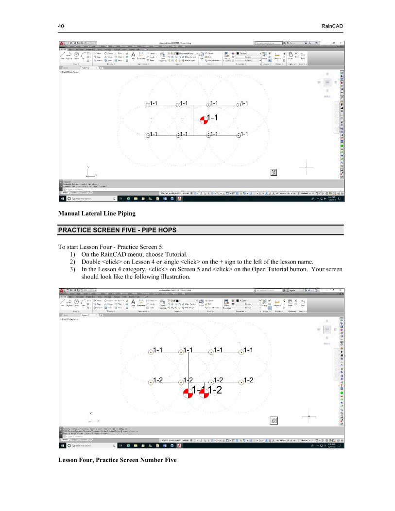
40 RainCAD
Manual Lateral Line Piping
PRACTICE SCREEN FIVE - PIPE HOPS
To start Lesson Four - Practice Screen 5: 1) On the RainCAD menu, choose Tutorial. 2) Double <click> on Lesson 4 or single <click> on the + sign to the left of the lesson name. 3) In the Lesson 4 category, <click> on Screen 5 and <click> on the Open Tutorial button. Your screen
should look like the following illustration.
Lesson Four, Practice Screen Number Five
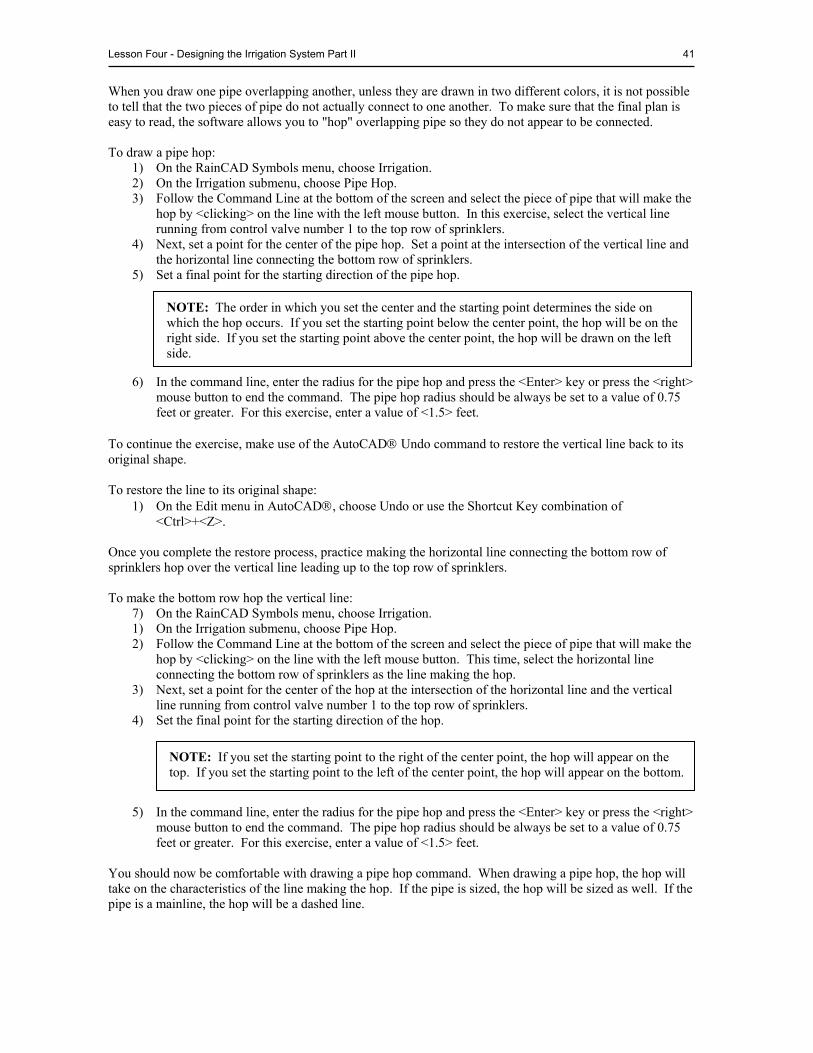
Lesson Four - Designing the Irrigation System Part II 41
When you draw one pipe overlapping another, unless they are drawn in two different colors, it is not possible to tell that the two pieces of pipe do not actually connect to one another. To make sure that the final plan is easy to read, the software allows you to "hop" overlapping pipe so they do not appear to be connected. To draw a pipe hop:
1) On the RainCAD Symbols menu, choose Irrigation. 2) On the Irrigation submenu, choose Pipe Hop. 3) Follow the Command Line at the bottom of the screen and select the piece of pipe that will make the
hop by <clicking> on the line with the left mouse button. In this exercise, select the vertical line running from control valve number 1 to the top row of sprinklers.
4) Next, set a point for the center of the pipe hop. Set a point at the intersection of the vertical line and the horizontal line connecting the bottom row of sprinklers.
5) Set a final point for the starting direction of the pipe hop.
6) In the command line, enter the radius for the pipe hop and press the <Enter> key or press the <right>
mouse button to end the command. The pipe hop radius should be always be set to a value of 0.75 feet or greater. For this exercise, enter a value of <1.5> feet.
To continue the exercise, make use of the AutoCAD Undo command to restore the vertical line back to its original shape. To restore the line to its original shape:
1) On the Edit menu in AutoCAD, choose Undo or use the Shortcut Key combination of <Ctrl>+<Z>.
Once you complete the restore process, practice making the horizontal line connecting the bottom row of sprinklers hop over the vertical line leading up to the top row of sprinklers. To make the bottom row hop the vertical line:
7) On the RainCAD Symbols menu, choose Irrigation. 1) On the Irrigation submenu, choose Pipe Hop. 2) Follow the Command Line at the bottom of the screen and select the piece of pipe that will make the
hop by <clicking> on the line with the left mouse button. This time, select the horizontal line connecting the bottom row of sprinklers as the line making the hop.
3) Next, set a point for the center of the hop at the intersection of the horizontal line and the vertical line running from control valve number 1 to the top row of sprinklers.
4) Set the final point for the starting direction of the hop. 5) In the command line, enter the radius for the pipe hop and press the <Enter> key or press the <right>
mouse button to end the command. The pipe hop radius should be always be set to a value of 0.75 feet or greater. For this exercise, enter a value of <1.5> feet.
You should now be comfortable with drawing a pipe hop command. When drawing a pipe hop, the hop will take on the characteristics of the line making the hop. If the pipe is sized, the hop will be sized as well. If the pipe is a mainline, the hop will be a dashed line.
NOTE: The order in which you set the center and the starting point determines the side on which the hop occurs. If you set the starting point below the center point, the hop will be on the right side. If you set the starting point above the center point, the hop will be drawn on the left side.
NOTE: If you set the starting point to the right of the center point, the hop will appear on the top. If you set the starting point to the left of the center point, the hop will appear on the bottom.
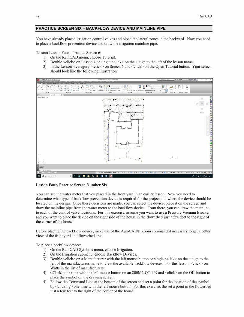
42 RainCAD
PRACTICE SCREEN SIX – BACKFLOW DEVICE AND MAINLINE PIPE
You have already placed irrigation control valves and piped the lateral zones in the backyard. Now you need to place a backflow prevention device and draw the irrigation mainline pipe. To start Lesson Four - Practice Screen 6:
1) On the RainCAD menu, choose Tutorial. 2) Double <click> on Lesson 4 or single <click> on the + sign to the left of the lesson name. 3) In the Lesson 4 category, <click> on Screen 6 and <click> on the Open Tutorial button. Your screen
should look like the following illustration.
Lesson Four, Practice Screen Number Six You can see the water meter that you placed in the front yard in an earlier lesson. Now you need to determine what type of backflow prevention device is required for the project and where the device should be located on the design. Once these decisions are made, you can select the device, place it on the screen and draw the mainline pipe from the water meter to the backflow device. From there, you can draw the mainline to each of the control valve locations. For this exercise, assume you want to use a Pressure Vacuum Breaker and you want to place the device on the right side of the house in the flowerbed just a few feet to the right of the corner of the house. Before placing the backflow device, make use of the AutoCAD Zoom command if necessary to get a better view of the front yard and flowerbed area. To place a backflow device:
1) On the RainCAD Symbols menu, choose Irrigation. 2) On the Irrigation submenu, choose Backflow Devices. 3) Double <click> on a Manufacturer with the left mouse button or single <click> on the + sign to the
left of the manufacturers name to view the available backflow devices. For this lesson, <click> on Watts in the list of manufacturers.
4) <Click> one time with the left mouse button on an 800M2-QT 1 ¼ and <click> on the OK button to place the symbol on the drawing screen.
5) Follow the Command Line at the bottom of the screen and set a point for the location of the symbol by <clicking> one time with the left mouse button. For this exercise, the set a point in the flowerbed just a few feet to the right of the corner of the house.
Lesson Four - Designing the Irrigation System Part II 43
6) Follow the Command Line again and set a second point to rotate the symbol at the desired angle. 7) Press the <Esc> key one time to end the command. 8) <Click> on the Close button to close the dialog box.
DRAWING THE MAINLINE PIPE
Now that a backflow device is on the design, it is time to draw the irrigation mainline pipe from the water source to each control valve in the system. To draw the mainline pipe:
1) On the RainCAD Symbols menu, choose Irrigation. 2) On the Irrigation submenu, choose Pipe Placement. 3) On the Pipe Placement dialog box, <click> on the Manual Piping tab. 4) Choose Mainline from the Pipe Type drop down menu by <clicking> on the selection one time with
the left mouse button. 5) For the purpose of the tutorial, do not select a pipe category or size from the drop down menus. 6) <Click> on the OK button and follow the Command Line. 7) Move the mouse cursor to the water meter and <click> one time to begin drawing a line from the
center of the symbol. 8) Move the cursor up toward the backflow device to draw the mainline pipe from the water meter to
the backflow device and <click> one time on the backflow symbol.
9) Continue to set points as required drawing the mainline pipe from the backflow device to the backyard and out to each control valve. Remember to consider the actual path you will follow when installing the pipe while trying to keep straight lines as they result in a much more professional drawing.
10) Once you reach the final control valve, press the <Enter> key to end the pipe. 11) Press the <Esc> key to return to the Pipe Placement dialog box. 12) <Click> on the Close button to close the dialog box.
Draw pipe hops as necessary to indicate that the mainline pipe is not connected to the lateral piping using the Pipe Hop command as described earlier in this lesson. The mainline pipe is now complete and your drawing should look similar to the following illustration.
NOTE: When creating your designs, if you know what size the pipe should be, you can select the category and pipe size from the drop down menus. As you draw the pipe on the screen, it is automatically sized according to your selections. If you do not know the size, wait and make use of the Automatic Pipe Sizing command in RainCAD.
NOTE: If you are zoomed in on the drawing, make use of the AutoCAD scroll bars or the Pan command to move about the screen while drawing the mainline pipe.
NOTE: If a category and size of pipe are selected, you will have an option to place a pipe size label while drawing the mainline pipe. After setting two points to draw a piece of pipe, in the command line enter a <Y> to label the pipe or an <N> to refrain from placing a pipe size label.
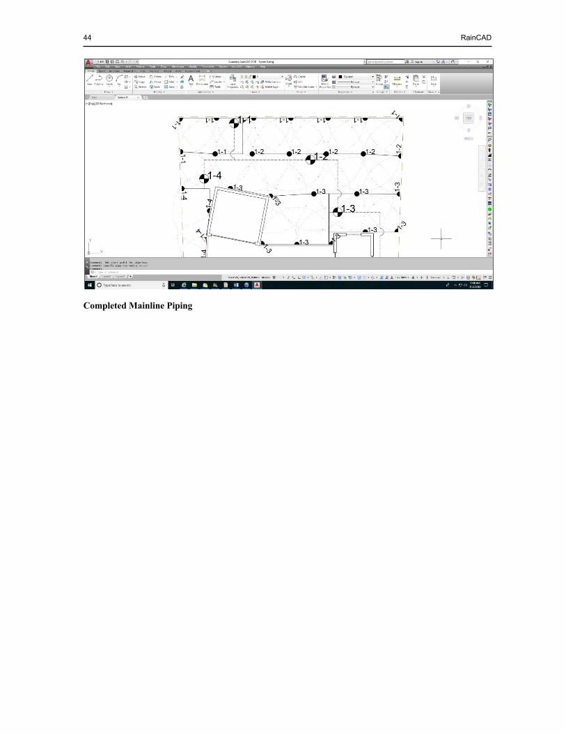
44 RainCAD
Completed Mainline Piping

LESSON FIVE - PIPE SIZING AND ADDITIONAL SYMBOLS
Estimated time to complete: 1 1/2 hours After completing Lesson Five, you should know how to:
Set preferences in the Irrigation Preferences dialog box Size pipe using the Automatic Pipe Sizing command Size pipe manually Place symbols for controllers, rain sensors and other accessories
To complete the system design phase you need to size the pipe correctly. In Lesson Five, you are going to practice the Automatic and Manual Pipe Sizing commands.
BEGINNING LESSON FIVE - IRRIGATION PREFERENCES
Before you begin the pipe sizing process, it may be beneficial to make some setting adjustments in the Irrigation Preferences dialog box. The Irrigation Preferences dialog box allows you to set certain properties to avoid the repetitive entry of information. Additional settings are available in the Automatic Pipe Sizing dialog box. Some of the properties associated with pipe are as follows:
Line Type Scale Setting for Mainline Pipe Size Label Type Pipe Size Label Offset Distance Pipe Size Label Leader Type Pipe Size Label Leader Colors Automatic Color Code Selections for Mainline and Zones Text Size for Pipe Size Labels Default Color for Pipe Size Labels
To set the irrigation preference settings for pipe sizing:
1) On the Options/Info menu in RainCAD, choose Irrigation. 2) On the Irrigation submenu, choose Preferences. 3) On the Irrigation Preferences dialog box, <click> on the Pipe tab or Text Style tab 4) Make adjustments to the settings as necessary. 5) Once all settings are made, <click> on the Close button to exit the dialog box and save the settings.
For more information on preference settings, refer to the Help screens in RainCAD under Irrigation Preferences, Pipe Preferences or Text Styles.
PIPE SIZING OPTIONS
Prior to sizing lateral line or mainline pipe, it may be necessary to adjust the available option settings. Any adjustments to the settings will be saved until further adjustments are required. To adjust the pipe sizing option settings:
1) On the RainCAD Calcs menu, choose Irrigation. 2) On the Irrigation submenu, choose Automatic Pipe Sizing. 3) On the Automatic Pipe Sizing dialog box, <click> on the Options tab.
NOTE: If the Automatically Color Code Pipe check box is enabled in the Automatic Pipe Sizing command, the color of the mainline pipe and the color of the lateral line zones will be based on the settings under the Auto Pipe Color settings. If the Automatically Color Code Pipe check box is disabled, the pipe will be colored based on the settings in the Pipe Database.
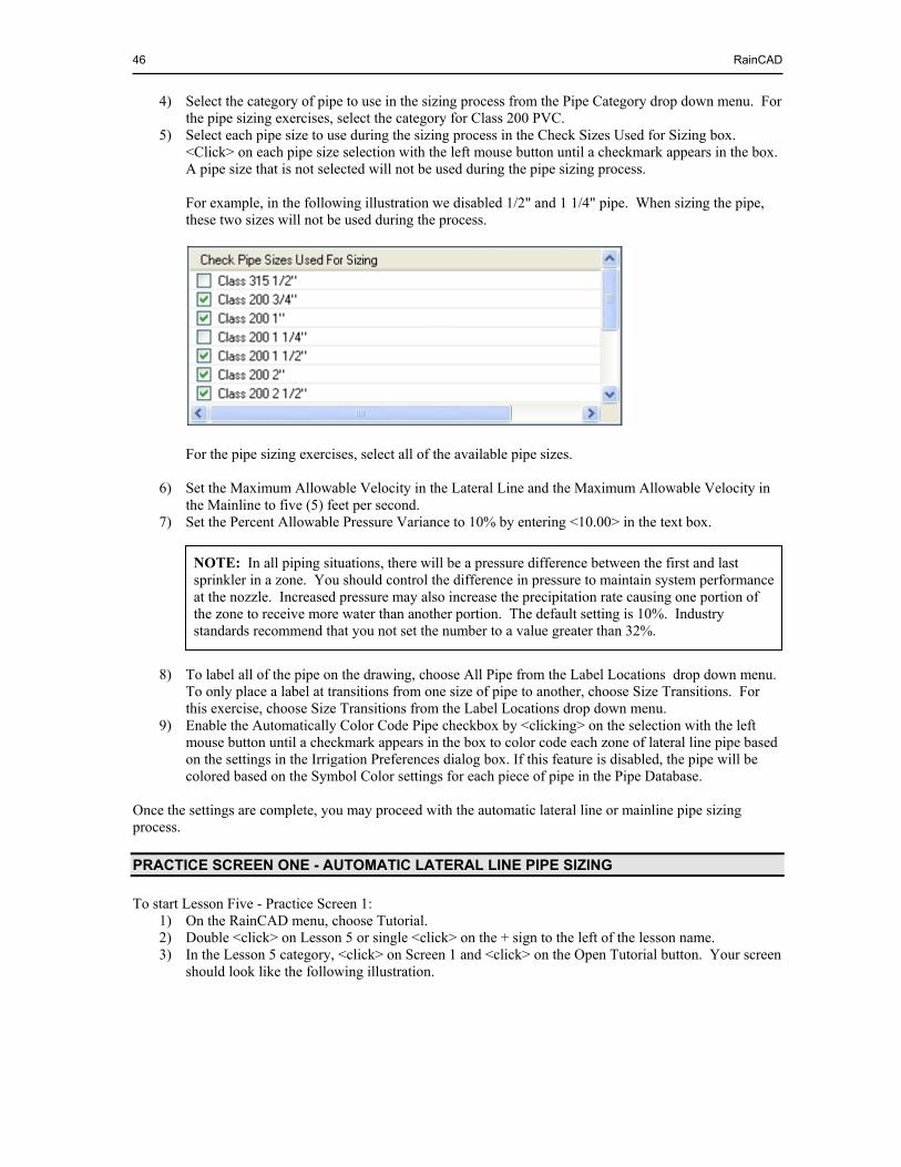
46 RainCAD
4) Select the category of pipe to use in the sizing process from the Pipe Category drop down menu. For the pipe sizing exercises, select the category for Class 200 PVC.
5) Select each pipe size to use during the sizing process in the Check Sizes Used for Sizing box. <Click> on each pipe size selection with the left mouse button until a checkmark appears in the box. A pipe size that is not selected will not be used during the pipe sizing process. For example, in the following illustration we disabled 1/2" and 1 1/4" pipe. When sizing the pipe, these two sizes will not be used during the process.
For the pipe sizing exercises, select all of the available pipe sizes.
6) Set the Maximum Allowable Velocity in the Lateral Line and the Maximum Allowable Velocity in the Mainline to five (5) feet per second.
7) Set the Percent Allowable Pressure Variance to 10% by entering <10.00> in the text box. 8) To label all of the pipe on the drawing, choose All Pipe from the Label Locations drop down menu.
To only place a label at transitions from one size of pipe to another, choose Size Transitions. For this exercise, choose Size Transitions from the Label Locations drop down menu.
9) Enable the Automatically Color Code Pipe checkbox by <clicking> on the selection with the left mouse button until a checkmark appears in the box to color code each zone of lateral line pipe based on the settings in the Irrigation Preferences dialog box. If this feature is disabled, the pipe will be colored based on the Symbol Color settings for each piece of pipe in the Pipe Database.
Once the settings are complete, you may proceed with the automatic lateral line or mainline pipe sizing process.
PRACTICE SCREEN ONE - AUTOMATIC LATERAL LINE PIPE SIZING
To start Lesson Five - Practice Screen 1: 1) On the RainCAD menu, choose Tutorial. 2) Double <click> on Lesson 5 or single <click> on the + sign to the left of the lesson name. 3) In the Lesson 5 category, <click> on Screen 1 and <click> on the Open Tutorial button. Your screen
should look like the following illustration.
NOTE: In all piping situations, there will be a pressure difference between the first and last sprinkler in a zone. You should control the difference in pressure to maintain system performance at the nozzle. Increased pressure may also increase the precipitation rate causing one portion of the zone to receive more water than another portion. The default setting is 10%. Industry standards recommend that you not set the number to a value greater than 32%.
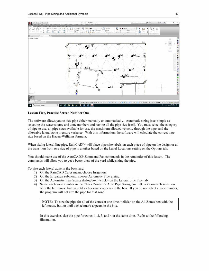
Lesson Five - Pipe Sizing and Additional Symbols 47
Lesson Five, Practice Screen Number One The software allows you to size pipe either manually or automatically. Automatic sizing is as simple as selecting the water source and zone numbers and having all the pipe size itself. You must select the category of pipe to use, all pipe sizes available for use, the maximum allowed velocity through the pipe, and the allowable lateral zone pressure variance. With this information, the software will calculate the correct pipe size based on the Hazen-Williams formula. When sizing lateral line pipe, RainCAD will place pipe size labels on each piece of pipe on the design or at the transition from one size of pipe to another based on the Label Locations setting on the Options tab. You should make use of the AutoCAD Zoom and Pan commands in the remainder of this lesson. The commands will allow you to get a better view of the yard while sizing the pipe. To size each lateral zone in the backyard:
1) On the RainCAD Calcs menu, choose Irrigation. 2) On the Irrigation submenu, choose Automatic Pipe Sizing. 3) On the Automatic Pipe Sizing dialog box, <click> on the Lateral Line Pipe tab. 4) Select each zone number in the Check Zones for Auto Pipe Sizing box. <Click> on each selection
with the left mouse button until a checkmark appears in the box. If you do not select a zone number, the program will not size the pipe for that zone. In this exercise, size the pipe for zones 1, 2, 3, and 4 at the same time. Refer to the following illustration.
NOTE: To size the pipe for all of the zones at one time, <click> on the All Zones box with the left mouse button until a checkmark appears in the box.
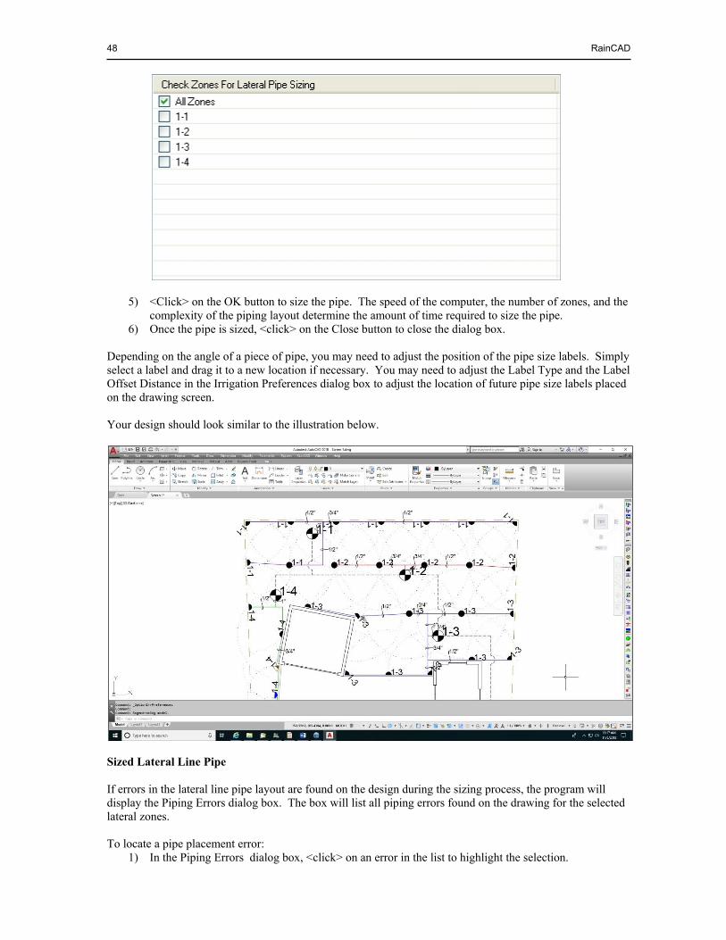
48 RainCAD
5) <Click> on the OK button to size the pipe. The speed of the computer, the number of zones, and the
complexity of the piping layout determine the amount of time required to size the pipe. 6) Once the pipe is sized, <click> on the Close button to close the dialog box.
Depending on the angle of a piece of pipe, you may need to adjust the position of the pipe size labels. Simply select a label and drag it to a new location if necessary. You may need to adjust the Label Type and the Label Offset Distance in the Irrigation Preferences dialog box to adjust the location of future pipe size labels placed on the drawing screen. Your design should look similar to the illustration below.
Sized Lateral Line Pipe If errors in the lateral line pipe layout are found on the design during the sizing process, the program will display the Piping Errors dialog box. The box will list all piping errors found on the drawing for the selected lateral zones. To locate a pipe placement error:
1) In the Piping Errors dialog box, <click> on an error in the list to highlight the selection.
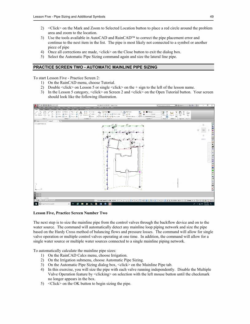
Lesson Five - Pipe Sizing and Additional Symbols 49
2) <Click> on the Mark and Zoom to Selected Location button to place a red circle around the problem area and zoom to the location.
3) Use the tools available in AutoCAD and RainCAD to correct the pipe placement error and continue to the next item in the list. The pipe is most likely not connected to a symbol or another piece of pipe
4) Once all corrections are made, <click> on the Close button to exit the dialog box. 5) Select the Automatic Pipe Sizing command again and size the lateral line pipe.
PRACTICE SCREEN TWO - AUTOMATIC MAINLINE PIPE SIZING
To start Lesson Five - Practice Screen 2: 1) On the RainCAD menu, choose Tutorial. 2) Double <click> on Lesson 5 or single <click> on the + sign to the left of the lesson name. 3) In the Lesson 5 category, <click> on Screen 2 and <click> on the Open Tutorial button. Your screen
should look like the following illustration.
Lesson Five, Practice Screen Number Two The next step is to size the mainline pipe from the control valves through the backflow device and on to the water source. The command will automatically detect any mainline loop piping network and size the pipe based on the Hardy Cross method of balancing flows and pressure losses. The command will allow for single valve operation or multiple control valves operating at one time. In addition, the command will allow for a single water source or multiple water sources connected to a single mainline piping network. To automatically calculate the mainline pipe sizes:
1) On the RainCAD Calcs menu, choose Irrigation. 2) On the Irrigation submenu, choose Automatic Pipe Sizing. 3) On the Automatic Pipe Sizing dialog box, <click> on the Mainline Pipe tab. 4) In this exercise, you will size the pipe with each valve running independently. Disable the Multiple
Valve Operation feature by <clicking> on selection with the left mouse button until the checkmark no longer appears in the box.
5) <Click> on the OK button to begin sizing the pipe.

50 RainCAD
Depending on the speed of the computer, the number of control valves, and the complexity of the piping layout, it will take a short period to size the pipe from the control valves back to each water source.
If more than one control valve will operate simultaneously, you will need to create Run Sets and assign each control valve to one or more Run Sets. To add, delete, or assign a control valve to a run set:
1) On the RainCAD Calcs menu, choose Irrigation. 2) On the Irrigation submenu, choose Automatic Pipe Sizing. 3) On the Automatic Pipe Sizing dialog box, <click> on the Mainline Pipe tab. 4) Enable the Multiple Valve Operation check box by <clicking> on the selection with the left mouse
button until a checkmark appears in the box. 5) To create a new Run Set, <click> on the Add Set button. You may create as many different Run
Sets as required. 6) To place control valves into a Run Set, <click> on the desired Run Set in the selection box on the
right side of the dialog box. <Click> on a control valve in the list on the left side of the dialog box and <click> on the right arrow button, or double <click> on the control valve number. The control valve number will be placed to the right of the Run Set number.
7) To remove a control valve from the selected Run Set, <click> on the control valve in the list on the left side of the dialog box and <click> on the left arrow button. The control valve number will be removed from the right of the Run Set number.
8) To delete a Run Set from the list, select the desired Run Set in the list on the right side of the dialog box and <click> on the Delete Set button.
9) To calculate the flow of a Run Set, <click> on the Get Set Flow button. 10) Once all possible Run Sets have been created, <click> on the OK button to begin the pipe sizing
process. The Run Set configuration along with the adjustment of the velocity in the mainline can greatly affect the sizing of pipe within the system. If the sizes are not satisfactory, you may adjust the settings and resize the system until you are satisfied with the results. Once the pipe is sized, the Mainline Pipe Details viewer will appear. The Mainline Pipe Details viewer will allow you to select a piece of pipe on the screen and view more detailed information such as the size, length, flow, velocity, and pressure loss. To view the hydraulic information on a specific piece of pipe:
1) In the Run Set location near the top of the dialog box, <click> on the down arrow to view a list of the available run sets. Select a run set from the resulting menu by <clicking> on the selection with the left mouse button. Refer to the following illustration.
NOTE: RainCAD will size mainline pipe in a loop network. There is no limit to the number of loops that may exist within the network. The loops may be totally independent of one another. The program will also size mainline with more than one water source connected to the piping network.
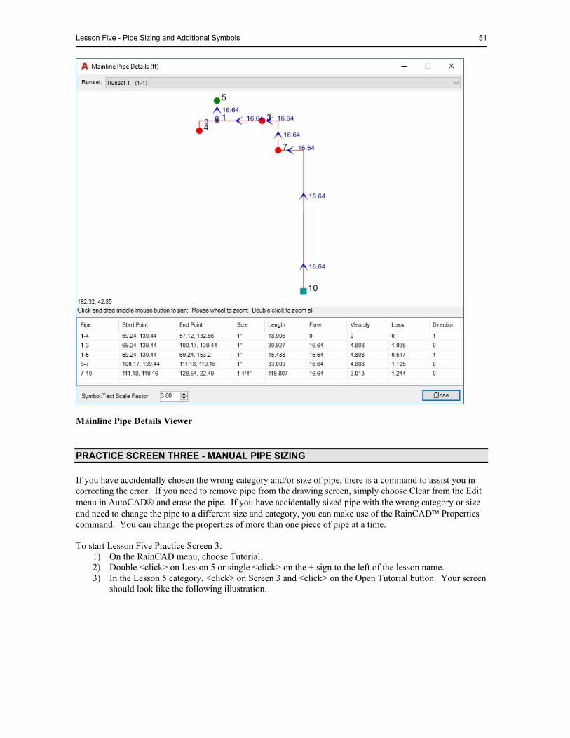
Lesson Five - Pipe Sizing and Additional Symbols 51
Mainline Pipe Details Viewer
PRACTICE SCREEN THREE - MANUAL PIPE SIZING
If you have accidentally chosen the wrong category and/or size of pipe, there is a command to assist you in correcting the error. If you need to remove pipe from the drawing screen, simply choose Clear from the Edit menu in AutoCAD and erase the pipe. If you have accidentally sized pipe with the wrong category or size and need to change the pipe to a different size and category, you can make use of the RainCAD Properties command. You can change the properties of more than one piece of pipe at a time. To start Lesson Five Practice Screen 3:
1) On the RainCAD menu, choose Tutorial. 2) Double <click> on Lesson 5 or single <click> on the + sign to the left of the lesson name. 3) In the Lesson 5 category, <click> on Screen 3 and <click> on the Open Tutorial button. Your screen
should look like the following illustration.

52 RainCAD
Lesson Five, Practice Screen Number Three We mistakenly sized the lateral line pipe as Class 315 PVC. In fact, for the 3/4" and 1" piping, Class 200 PVC pipe was the desired choice. You do not need to erase the pipe and redraw it; you just need to change it to the correct size and category. To change pipe to a different size and category:
1) On the RainCAD Options/Info, choose Properties. 2) Select each piece of 3/4" pipe by <clicking> on the pipe one time with the mouse. 3) <Click> on the Category drop down menu and <click> on a category of pipe from the list. For this
exercise, <click> on Class 200 PVC in the list of category names. 4) <Click> on the Pipe Size drop down menu and <click> on the desired size in the list. For this
exercise, <click> on Class 200 PVC 3/4”. 5) As soon as you click out of one box or drop down menu to another, the pipe on the drawing screen
change to the new category and size assignment. 6) Press the Escape key to unselect the pipe. 7) Follow the steps above to change the Class 315 PVC 1” pipe to Class 200 PVC 1” pipe.
All of the three-quarter and one inch Class 315 PVC pipe should now be Class 200 PVC.
PRACTICE SCREEN FOUR - CONTROLLERS AND ACCESSORY SYMBOLS
If the irrigation design is complete, you should now know how many zones or control valves exist in the system. You can now add other symbols such as the irrigation controller and rain sensor. If this were a commercial project, you may want to add isolation valves, quick coupler valves or a weather station. RainCAD will count all of the additional equipment in the material takeoff or estimate/proposal. To start Lesson Five Practice Screen 4:
1) On the RainCAD menu, choose Tutorial. 2) Double <click> on Lesson 5 or single <click> on the + sign to the left of the lesson name. 3) In the Lesson 5 category, <click> on Screen 4 and <click> on the Open Tutorial button. Your screen
should look like the following illustration.
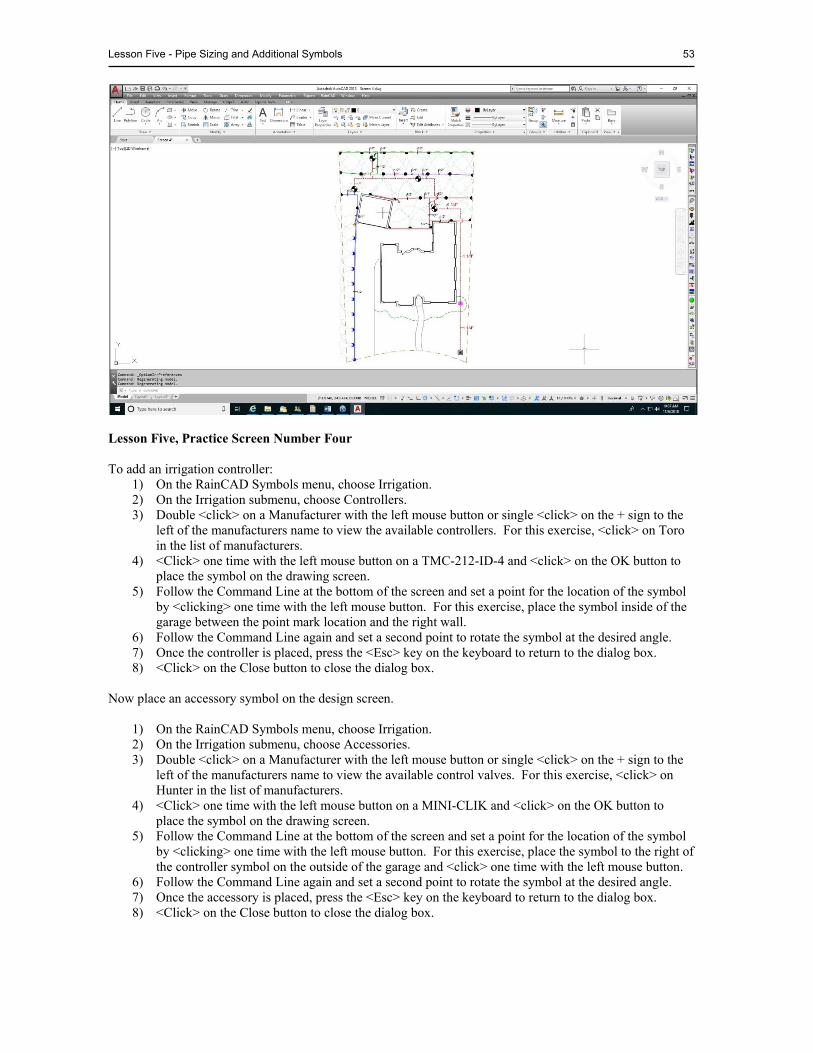
Lesson Five - Pipe Sizing and Additional Symbols 53
Lesson Five, Practice Screen Number Four To add an irrigation controller:
1) On the RainCAD Symbols menu, choose Irrigation. 2) On the Irrigation submenu, choose Controllers. 3) Double <click> on a Manufacturer with the left mouse button or single <click> on the + sign to the
left of the manufacturers name to view the available controllers. For this exercise, <click> on Toro in the list of manufacturers.
4) <Click> one time with the left mouse button on a TMC-212-ID-4 and <click> on the OK button to place the symbol on the drawing screen.
5) Follow the Command Line at the bottom of the screen and set a point for the location of the symbol by <clicking> one time with the left mouse button. For this exercise, place the symbol inside of the garage between the point mark location and the right wall.
6) Follow the Command Line again and set a second point to rotate the symbol at the desired angle. 7) Once the controller is placed, press the <Esc> key on the keyboard to return to the dialog box. 8) <Click> on the Close button to close the dialog box.
Now place an accessory symbol on the design screen.
1) On the RainCAD Symbols menu, choose Irrigation. 2) On the Irrigation submenu, choose Accessories. 3) Double <click> on a Manufacturer with the left mouse button or single <click> on the + sign to the
left of the manufacturers name to view the available control valves. For this exercise, <click> on Hunter in the list of manufacturers.
4) <Click> one time with the left mouse button on a MINI-CLIK and <click> on the OK button to place the symbol on the drawing screen.
5) Follow the Command Line at the bottom of the screen and set a point for the location of the symbol by <clicking> one time with the left mouse button. For this exercise, place the symbol to the right of the controller symbol on the outside of the garage and <click> one time with the left mouse button.
6) Follow the Command Line again and set a second point to rotate the symbol at the desired angle. 7) Once the accessory is placed, press the <Esc> key on the keyboard to return to the dialog box. 8) <Click> on the Close button to close the dialog box.

54 RainCAD
CONTROLLER/STATION ASSIGNMENTS
Controller symbols on an irrigation design are normally given an identification such as A, B, AA, etcetera. Control valves are then assigned to each station on the controller and given an identification such as A1, B3, or AA10. To assign the selected controller symbol on the drawing screen to an identification:
1) <Click> one time on the controller symbol you just placed inside of the garage. 2) On the RainCAD Calcs menu, choose Irrigation. 3) On the Irrigation submenu, chose Controller/Station Assignments. 4) On the Controller/Station Assignments dialog box, <click> on the Controller Assignment tab. 5) The list of controllers found on the drawing screen are displayed on the left side of the dialog box.
Each controller in the list is marked with a triangle symbol. Double <click> on a Controller Description with the left mouse button or single <click> on the + sign to the left of the controller to view the available stations.
6) To assign an identifier to a controller, <click> on the controller description, press the <right> mouse button and <click> on Set Controller Identifier. In the identifier dialog box, enter an identifier for the controller such as A, B, or C and click on the OK button.. Identification strings should not be any longer than three characters in length. For this lesson, enter the letter “A” in the box and press the <Enter> key. The controller description will now read as TMC-212-ID-4 (A).
Now that the controller has been assigned an identification, you can now assign zones to specific stations on the controller. To assign zones to stations on a controller:
1) Double <click> on the controller description in the Station/Zone Assignment list with the left mouse button, or single <click> on the + sign to the left of the controller identifier to view the list of stations.
2) Single <click> one time on Station 1 under the controller description on the left side of the dialog box.
3) On the right side of the dialog box in the list of Water Source and Zone numbers, double <click> on 1- 1. A green valve symbol and a 1-1 will now appear under Station 1 in the list to indicate that this zone is assigned to the station.
4) Single <click> one time on Station 2 under the controller description on the left side of the dialog box, and double <click> on 1-2 on the right side of the dialog box to assign zone 2 to station 2 on the controller.
5) Continue in this manner to assign zone 3 to station 3 and zone 4 to station 4 on the controller.
VALVE NOTATIONS
The Valve Notation command allows you to place specific valve and zone information on the drawing screen. There are multiple valve notations from which to choose. Each notation includes the controller identifier and station assignment number, the size of the control valve, and the flow of water through the valve. To place a valve notation symbol on the drawing screen:
7) On the RainCAD Symbols menu, choose Irrigation. 8) On the Irrigation submenu, chose Valve Notations. 9) Select a Water Source and Zone Number from the WS/Zone box by clicking on the selection one
time with the left mouse button. For this exercise, select 1-2. 10) Enter a value for the size of the notation in the Notation Size box. Enter a value of <8> for this
exercise.
NOTE: If more than one controller is found on the drawing screen, the controllers will be listed in the order in which they are found. You may adjust the order by <clicking> on a controller description and <clicking> on the up or down arrow buttons just below the listing.
Lesson Five - Pipe Sizing and Additional Symbols 55
11) Select a valve Notation Type by <clicking> on the drop down arrow to locate the symbol in the Symbol Browser dialog box. <Click> on the desired symbol to accept the assignment.
12) <Click> on the Place/Update Notation button to place the symbol on the drawing screen. 13) Follow the Command Line again and set a point on the screen for the center of the valve notation
symbol. To move the valve notation symbol, select the symbol and make use of the AutoCAD Move command. You may edit any of the text by selecting the text and using the AutoCAD Properties command.
PLACING SLEEVE SYMBOLS
A sleeve is a piece of pipe placed under a hardscape area such as a driveway, walkway, or parking lot. The sleeve is used to run lateral line, mainline, or control wire under the hardscape area. Even though you have not actually completed an entire irrigation design, place a sleeving symbol under the front sidewalk. Make use of the AutoCAD Zoom command to get a good view of the front yard and sidewalk. To place a sleeve symbol on the drawing:
1) On the RainCAD Symbols menu, choose Irrigation. 2) On the Irrigation submenu, choose Sleeving. 3) Double <click> on a Pipe Category with the left mouse button or single <click> on the + sign to the
left of the category name to view the available pipe selections. For this exercise, select Schedule 40 PVC.
4) <Click> one time with the left mouse button on a piece of pipe. Select Schedule 40 2” and <click> on the OK button.
5) <Click> on the Hatch Pattern button (...) to open the Hatch Pattern Palette dialog box. Select the desired hatch pattern in the dialog box and then <click> on the OK button to accept the pattern assignment.
6) Next, enter the Hatch Angle setting and the Hatch Scale in the appropriate text boxes. 7) In the Width text box, enter the desired width for the sleeving symbol. 8) <Click> on the Alignment drop down menu and select either Right, Center, or Left for the alignment
of the sleeving symbol. For this exercise, select a Center alignment. 9) <Click> on the OK button to place the sleeve symbol on the drawing screen. 10) Follow the Command Line at the bottom of the screen. Set a starting point for the sleeve symbol.
For this exercise, set the starting point halfway down the sidewalk, to the left and outside. 11) Set a second point for the end of the sleeve symbol directly to the right on the opposite side outside
of the sidewalk. 12) To continue placing sleeve symbols, <click> on the OK button and repeat the process. 13) <Click> on the Close button to close the Sleeving Placement dialog box.
IRRIGATION INSTALLATION DETAILS
Installation details make the design easier for the installer to understand by indicating the precise method of installation. With small designs, which include most residential drawings, you may be able to place the installation details right on the drawing page. If this is a large commercial project, simply create a new drawing. The new drawing may consist of a title block, a legend, and installation details. To place an irrigation installation detail on the drawing:
1) On the RainCAD Symbols menu, choose Installation Details. 2) On the Installation Details submenu, choose Irrigation. 3) Double <click> on a Manufacturer with the left mouse button or single <click> on the + sign to the
left of the manufacturers name to view the available category or installation details. For this lesson, <click> on Rain Bird in the list of manufacturers.
NOTE: If you change the controller and station assignment, the size of the control valve, or the flow of the zone, <click> on the WS/Zone selection and click on the Place/Update Notation button to update the information in the existing valve notation symbol.
56 RainCAD
4) Double <click> on a Category with the left mouse button or single <click> on the + sign to the left of the category name to view the available installation details. For this lesson, <click> on Sprays in the list of categories.
5) <Click> one time with the left mouse button on 1804 on a Swing Joint and <click> on the OK button.
6) Follow the Command Line at the bottom of the screen and set a point for the detail location. For this exercise, set a point on the right side of the house outside of the property line.
7) Follow the Command Line and set a second point for the rotation angle of the detail. Set the second point directly to the right of the original point.
8) <Click> on the Close button to close the dialog box. To move or scale the detail symbol, make use of the AutoCAD Move and Scale commands.
NOTE: The equipment manufacturers created most of the irrigation installation details in RainCAD. RainCAD does not have installation details for each piece of equipment in the program. You may create your own details or modify any of the existing detail drawings to meet your specifications.
NOTE: The list of categories and file names are read straight from the directory and file structure as created in Windows Explorer. This allows the use of sub-folders to create sub-
LESSON SIX - LANDSCAPE DESIGN
Estimated time to complete: 1 1/2 hours After completing Lesson Six, you should be familiar with:
Searching the plant database Placing plants on the drawing screen Placing symbol designators Performing area/volume calculations Placing miscellaneous symbols Automatic Symbol Layout
SEARCHING FOR PLANT MATERIAL
There may be times when you need a little help in finding the right plant for a particular setting. The Plant Search function will assist you in finding plant material within the database. You select or enter the criteria for the species data and the software will search the database for any matching plant material. A list of all matches will be displayed in the dialog box. To search the plant database:
1) On the RainCAD Symbols menu, choose Landscape. 2) On the Landscape submenu, choose Plant Material. 3) On the Plant Placement dialog box, <click> on the Plant Search tab. 4) Select the desired species data from the drop down menus or enter the necessary criteria in a text
box. 5) Once the desired selection criteria is chosen, <click> on the Search button. The program will
display the plant material meeting the criteria in the tree on the left side of the dialog box. 6) Double <click> on a category with the left mouse button or single <click> on the + sign to the left of
the category name to view the list of matching plant selections. If a plant category does not have a + sign to the left of the category name, there are no plants in this category that meet the selected criteria.
To clear the search criteria, <click> on the Reset Fields button to reset all of the search criteria fields back to their beginning values.
PRACTICE SCREEN ONE - PLACING PLANT SYMBOLS
You can place plant symbols on the drawing screen either manually or with one of several different automatic placement features. Using the automatic features, you can place symbols along an existing or temporary polyline, or within a boundary line. To start Lesson Six Practice Screen 1:
1) On the RainCAD menu, choose Tutorial. 2) Double <click> on Lesson 6 or single <click> on the + sign to the left of the lesson name.
NOTE: You assign symbols to each plant in the Plants Database. RainCAD comes with hundreds of individual plant symbols or symbol combinations. In addition, you can assign AutoCAD hatching patterns and gradient fills. You may edit any of the individual symbols or create your own symbols for assignment to the plant material.
NOTE: It is not necessary to make a selection or enter a value for each field. For example, assume you are looking for plant with a three-inch flower with a pink blossom. Simply <click> on the Flower Color drop down menu and select Pink by <clicking> on the selection one time with the left mouse button. Enter a <3> in the Flower Size text box. Refer to Lesson Eight for more information on entering the species data in the Plants Database.
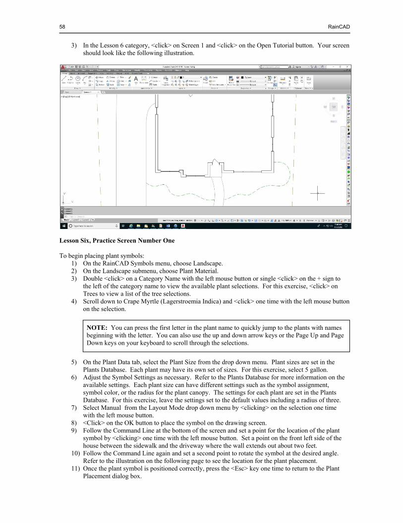
58 RainCAD
3) In the Lesson 6 category, <click> on Screen 1 and <click> on the Open Tutorial button. Your screen should look like the following illustration.
Lesson Six, Practice Screen Number One To begin placing plant symbols:
1) On the RainCAD Symbols menu, choose Landscape. 2) On the Landscape submenu, choose Plant Material. 3) Double <click> on a Category Name with the left mouse button or single <click> on the + sign to
the left of the category name to view the available plant selections. For this exercise, <click> on Trees to view a list of the tree selections.
4) Scroll down to Crape Myrtle (Lagerstroemia Indica) and <click> one time with the left mouse button on the selection.
5) On the Plant Data tab, select the Plant Size from the drop down menu. Plant sizes are set in the
Plants Database. Each plant may have its own set of sizes. For this exercise, select 5 gallon. 6) Adjust the Symbol Settings as necessary. Refer to the Plants Database for more information on the
available settings. Each plant size can have different settings such as the symbol assignment, symbol color, or the radius for the plant canopy. The settings for each plant are set in the Plants Database. For this exercise, leave the settings set to the default values including a radius of three.
7) Select Manual from the Layout Mode drop down menu by <clicking> on the selection one time with the left mouse button.
8) <Click> on the OK button to place the symbol on the drawing screen. 9) Follow the Command Line at the bottom of the screen and set a point for the location of the plant
symbol by <clicking> one time with the left mouse button. Set a point on the front left side of the house between the sidewalk and the driveway where the wall extends out about two feet.
10) Follow the Command Line again and set a second point to rotate the symbol at the desired angle. Refer to the illustration on the following page to see the location for the plant placement.
11) Once the plant symbol is positioned correctly, press the <Esc> key one time to return to the Plant Placement dialog box.
NOTE: You can press the first letter in the plant name to quickly jump to the plants with names beginning with the letter. You can also use the up and down arrow keys or the Page Up and Page Down keys on your keyboard to scroll through the selections.
Lesson Six - Landscape Design 59
Now place a few small shrubs in the flowerbed and then place ground cover along the front edge similar to the illustration on the following page.
1) In the Plant Placement dialog box, select Shrubs Under 4 Feet from the category listings on the left
side of the dialog box. 2) Select Azalea (Azalea Indica) from the list by <clicking> on the selection one time with the mouse. 3) On the Plant Data tab, select the Plant Size from the drop down menu. For this exercise, select 1
gallon. 4) Leave the plant canopy radius to the database setting of two. 5) Leave the Layout Mode set to Manual and <click> on the OK button to begin placing plant symbols
on the drawing screen. 6) Follow the Command Line at the bottom of the screen and set a point for the location of the plant
symbol by <clicking> one time with the left mouse button. 7) Follow the Command Line again and set a second point to rotate the symbol at the desired angle. 8) Continue setting points for additional symbols. Refer to the illustration on the following page for
plant locations. 9) Once the plant symbols are placed, press the <Esc> key one time to return to the Plant Placement
dialog box. In most instances, ground cover and annual flowers are assigned to hatch patterns or gradient fills versus individual plant symbols. To place ground cover along the front portion of the flower bed:
1) If the Plant Placement dialog box is not open, restart the command from the RainCAD Symbols menu, the Landscape submenu.
2) In the Plant Placement dialog box, select Ground Cover-Vines from the category listings on the left side of the dialog box.
3) Select Creeping Lily Turf (Liriope Spicata) from the list by <clicking> on the selection one time with the mouse.
4) On the Plant data tab, select the Plant Size from the drop down menu. For this exercise, select Each for the plant size.
5) The Symbol Type and the Fill Type should be set to Hatch. 6) For this exercise, leave the default setting of ANSI31 as the desired pattern for the plant material. 7) Leave the default Hatch Angle of 0, the Hatch Scale of 2.5, and the Hatch Color setting of blue.
8) <Click> on the OK button to begin outlining the area to fill with a hatch pattern. 9) Follow the Command Line at the bottom of the screen. Set multiple points to outline the front of the
flowerbed area with a polyline and press <Enter> to end the command. 10) <Click> on the Close button to close the dialog box.
Your design should now look similar to the following illustration.
NOTE: If Gradient is selected as the Fill Type, you can temporarily adjust the Gradient Type, the Gradient Angle, the Fill Color 1 and Fill Color 2 selections.
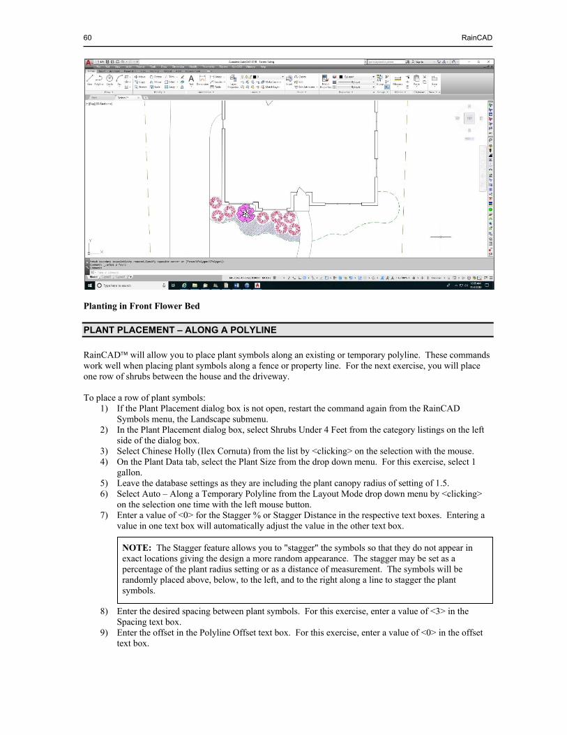
60 RainCAD
Planting in Front Flower Bed
PLANT PLACEMENT – ALONG A POLYLINE
RainCAD will allow you to place plant symbols along an existing or temporary polyline. These commands work well when placing plant symbols along a fence or property line. For the next exercise, you will place one row of shrubs between the house and the driveway. To place a row of plant symbols:
1) If the Plant Placement dialog box is not open, restart the command again from the RainCAD Symbols menu, the Landscape submenu.
2) In the Plant Placement dialog box, select Shrubs Under 4 Feet from the category listings on the left side of the dialog box.
3) Select Chinese Holly (Ilex Cornuta) from the list by <clicking> on the selection with the mouse. 4) On the Plant Data tab, select the Plant Size from the drop down menu. For this exercise, select 1
gallon. 5) Leave the database settings as they are including the plant canopy radius of setting of 1.5. 6) Select Auto – Along a Temporary Polyline from the Layout Mode drop down menu by <clicking>
on the selection one time with the left mouse button. 7) Enter a value of <0> for the Stagger % or Stagger Distance in the respective text boxes. Entering a
value in one text box will automatically adjust the value in the other text box.
8) Enter the desired spacing between plant symbols. For this exercise, enter a value of <3> in the Spacing text box.
9) Enter the offset in the Polyline Offset text box. For this exercise, enter a value of <0> in the offset text box.
NOTE: The Stagger feature allows you to "stagger" the symbols so that they do not appear in exact locations giving the design a more random appearance. The stagger may be set as a percentage of the plant radius setting or as a distance of measurement. The symbols will be randomly placed above, below, to the left, and to the right along a line to stagger the plant symbols.
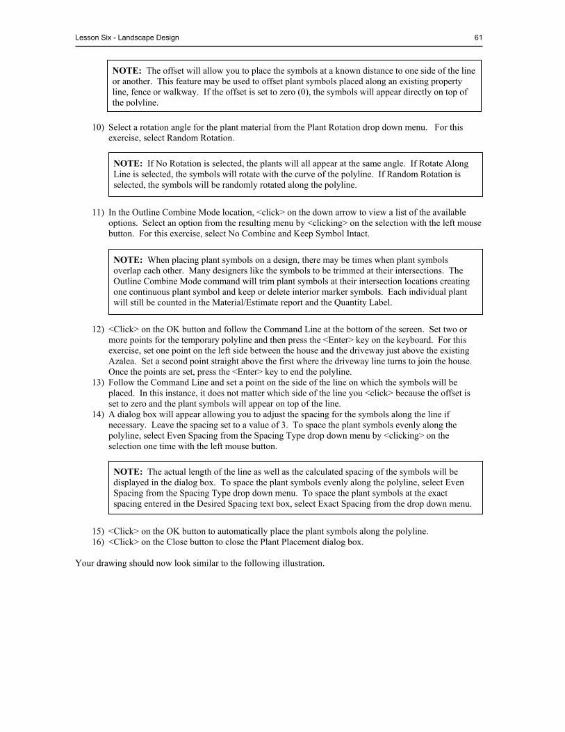
Lesson Six - Landscape Design 61
10) Select a rotation angle for the plant material from the Plant Rotation drop down menu. For this exercise, select Random Rotation.
11) In the Outline Combine Mode location, <click> on the down arrow to view a list of the available options. Select an option from the resulting menu by <clicking> on the selection with the left mouse button. For this exercise, select No Combine and Keep Symbol Intact.
12) <Click> on the OK button and follow the Command Line at the bottom of the screen. Set two or more points for the temporary polyline and then press the <Enter> key on the keyboard. For this exercise, set one point on the left side between the house and the driveway just above the existing Azalea. Set a second point straight above the first where the driveway line turns to join the house. Once the points are set, press the <Enter> key to end the polyline.
13) Follow the Command Line and set a point on the side of the line on which the symbols will be placed. In this instance, it does not matter which side of the line you <click> because the offset is set to zero and the plant symbols will appear on top of the line.
14) A dialog box will appear allowing you to adjust the spacing for the symbols along the line if necessary. Leave the spacing set to a value of 3. To space the plant symbols evenly along the polyline, select Even Spacing from the Spacing Type drop down menu by <clicking> on the selection one time with the left mouse button.
15) <Click> on the OK button to automatically place the plant symbols along the polyline. 16) <Click> on the Close button to close the Plant Placement dialog box.
Your drawing should now look similar to the following illustration.
NOTE: The actual length of the line as well as the calculated spacing of the symbols will be displayed in the dialog box. To space the plant symbols evenly along the polyline, select Even Spacing from the Spacing Type drop down menu. To space the plant symbols at the exact spacing entered in the Desired Spacing text box, select Exact Spacing from the drop down menu.
NOTE: If No Rotation is selected, the plants will all appear at the same angle. If Rotate Along Line is selected, the symbols will rotate with the curve of the polyline. If Random Rotation is selected, the symbols will be randomly rotated along the polyline.
NOTE: When placing plant symbols on a design, there may be times when plant symbols overlap each other. Many designers like the symbols to be trimmed at their intersections. The Outline Combine Mode command will trim plant symbols at their intersection locations creating one continuous plant symbol and keep or delete interior marker symbols. Each individual plant will still be counted in the Material/Estimate report and the Quantity Label.
NOTE: The offset will allow you to place the symbols at a known distance to one side of the line or another. This feature may be used to offset plant symbols placed along an existing property line, fence or walkway. If the offset is set to zero (0), the symbols will appear directly on top of the polyline.
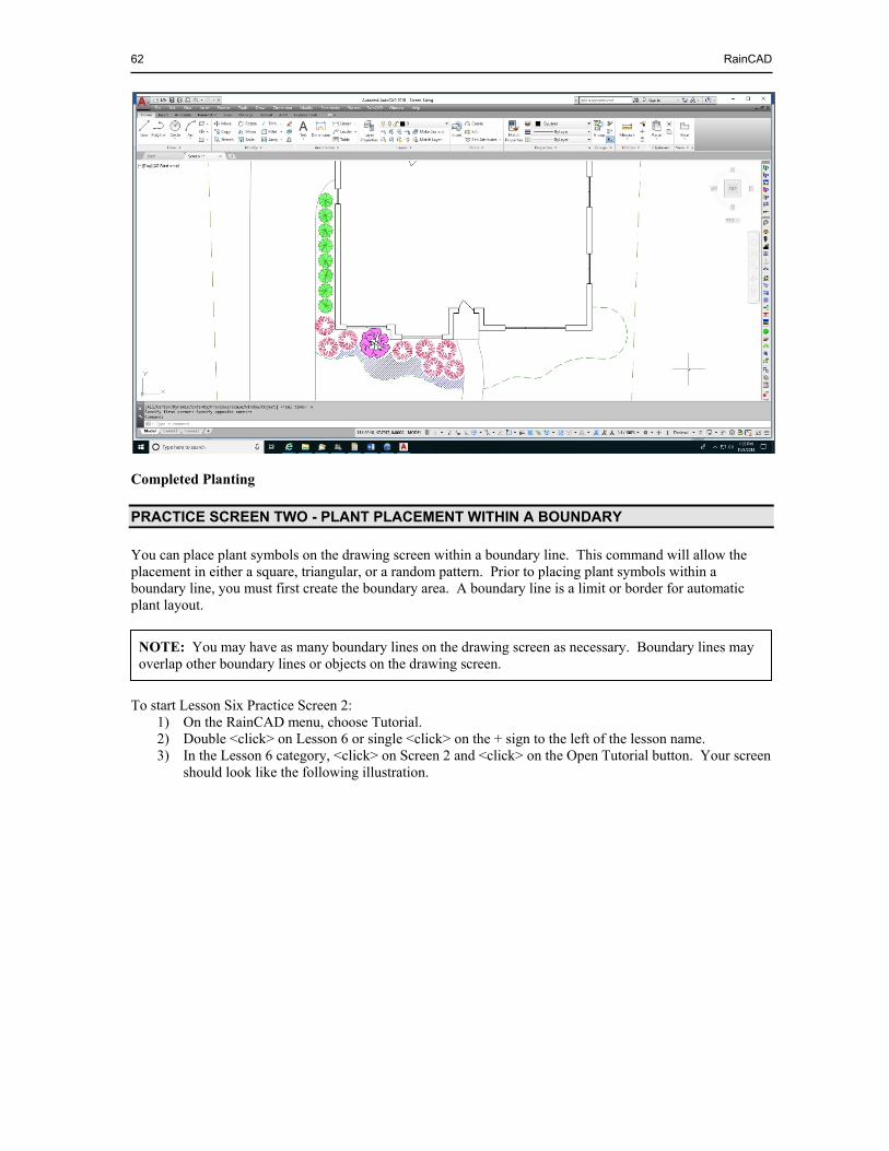
62 RainCAD
Completed Planting
PRACTICE SCREEN TWO - PLANT PLACEMENT WITHIN A BOUNDARY
You can place plant symbols on the drawing screen within a boundary line. This command will allow the placement in either a square, triangular, or a random pattern. Prior to placing plant symbols within a boundary line, you must first create the boundary area. A boundary line is a limit or border for automatic plant layout. To start Lesson Six Practice Screen 2:
1) On the RainCAD menu, choose Tutorial. 2) Double <click> on Lesson 6 or single <click> on the + sign to the left of the lesson name. 3) In the Lesson 6 category, <click> on Screen 2 and <click> on the Open Tutorial button. Your screen
should look like the following illustration.
NOTE: You may have as many boundary lines on the drawing screen as necessary. Boundary lines may overlap other boundary lines or objects on the drawing screen.
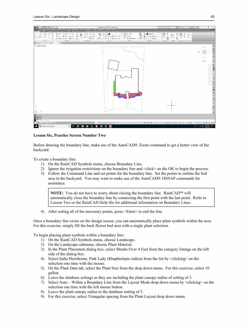
Lesson Six - Landscape Design 63
Lesson Six, Practice Screen Number Two Before drawing the boundary line, make use of the AutoCAD Zoom command to get a better view of the backyard. To create a boundary line:
1) On the RainCAD Symbols menu, choose Boundary Line. 2) Ignore the irrigation restrictions on the boundary line and <click> on the OK to begin the process. 3) Follow the Command Line and set points for the boundary line. Set the points to outline the bed
area in the backyard. You may want to make use of the AutoCAD OSNAP commands for assistance.
4) After setting all of the necessary points, press <Enter> to end the line. Once a boundary line exists on the design screen, you can automatically place plant symbols within the area. For this exercise, simply fill the back flower bed area with a single plant selection. To begin placing plant symbols within a boundary line:
1) On the RainCAD Symbols menu, choose Landscape. 2) On the Landscape submenu, choose Plant Material. 3) In the Plant Placement dialog box, select Shrubs Over 4 Feet from the category listings on the left
side of the dialog box. 4) Select India Hawthorne, Pink Lady (Rhaphiolepis indica) from the list by <clicking> on the
selection one time with the mouse. 5) On the Plant Data tab, select the Plant Size from the drop down menu. For this exercise, select 10
gallon. 6) Leave the database settings as they are including the plant canopy radius of setting of 3. 7) Select Auto – Within a Boundary Line from the Layout Mode drop down menu by <clicking> on the
selection one time with the left mouse button. 8) Leave the plant canopy radius to the database setting of 3. 9) For this exercise, select Triangular spacing from the Plant Layout drop down menu.
NOTE: You do not have to worry about closing the boundary line. RainCAD will automatically close the boundary line by connecting the first point with the last point. Refer to Lesson Two or the RainCAD Help file for additional information on Boundary Lines.

64 RainCAD
10) Enter a value of <0> for the Stagger % or Stagger Distance and Leave the Plant Offset set to 0. 11) Enter the desired distance between the plant materials in the Spacing text box. Enter a value of <6>
feet for this exercise. 12) Select a Plant Rotation angle from the drop down menu. When placing plants within a boundary
line, the rotation angle of along a line has the same affect as no rotation. 13) In the Boundary Control location, <click> on the down arrow to view a list of the available options.
Select 100% of plant radius can exceed boundary from the resulting menu by <clicking> on the selection with the left mouse button.
14) In the Outline Combine Mode location, <click> on the down arrow to view a list of options. Select an option from the resulting menu by <clicking> on the desired selection with the left mouse button.
15) <Click> on the OK button and follow Command Line at the bottom of the screen. 16) <Click> one time on the boundary line with the left mouse button to select the object.
17) The plant symbols will automatically be placed within the boundary line area. Delete the plant symbols from the drawing and try the command again using Square spacing for the layout. Using Random placement for the layout will create a grove of plant material. When Random is selected, you are required to enter a number of plants to appear in the boundary area in the Quantity box rather than a desired spacing between plant materials.
DELETING OR REPLACING PLANTS
Occasionally you may need to delete or replace plant material on a design. The Plant Properties command will allow you to select one or more plant symbols on the drawing screen and either replace the selected plants with another plant selection, replace all like plants, or delete all like plants from the design. For the purpose of the tutorial, replace the Chinese Holly along the side of the house with Japanese Boxwood. You should be on Lesson Six, Screen Two. Make use of the AutoCAD Zoom command to view the entire drawing. To delete or replace plant material on a design:
1) On the Options/Info menu in RainCAD, choose Properties. 2) Select one of the Chinese Holy plant symbols by <clicking> on the symbol one time with the mouse. 3) The Plant Properties dialog box will open with Chinese Holly as the selected plant material. 4) In the Select Matching Plants location, click on the Match Symbol checkbox until a check mark
appears and click on the Select button to select all matching plant symbols. 5) Leave the plant Category set to Shrubs Under 4 Feet. 6) <Click> on the Plant name drop down menu and scroll down to select Japanese Boxwood (Buxus
microphylla japonica) from the list by <clicking> on the selection one time with the mouse. 7) All Chinese Holly plant symbols on the design will be replaced with Japanese Boxwood.
PRACTICE SCREEN THREE - COMBINING PLANT SYMBOLS
When placing plant symbols on a design, there may be times when plant symbols overlap each other. Many designers like the symbols to be trimmed at their intersections. The Combine Plants command will trim plant symbols at their intersection locations creating one continuous plant symbol. Each individual plant will still be counted in the Material/Estimate report and the Quantity Label.
NOTE: When selecting a boundary line, pick an area where one boundary line is not drawn directly on top of another. This will prevent you from selecting the wrong boundary line.
NOTE: The Boundary Control provides different options to control the percentage of the plants canopy or radius that is allowed to appear outside of the boundary line.
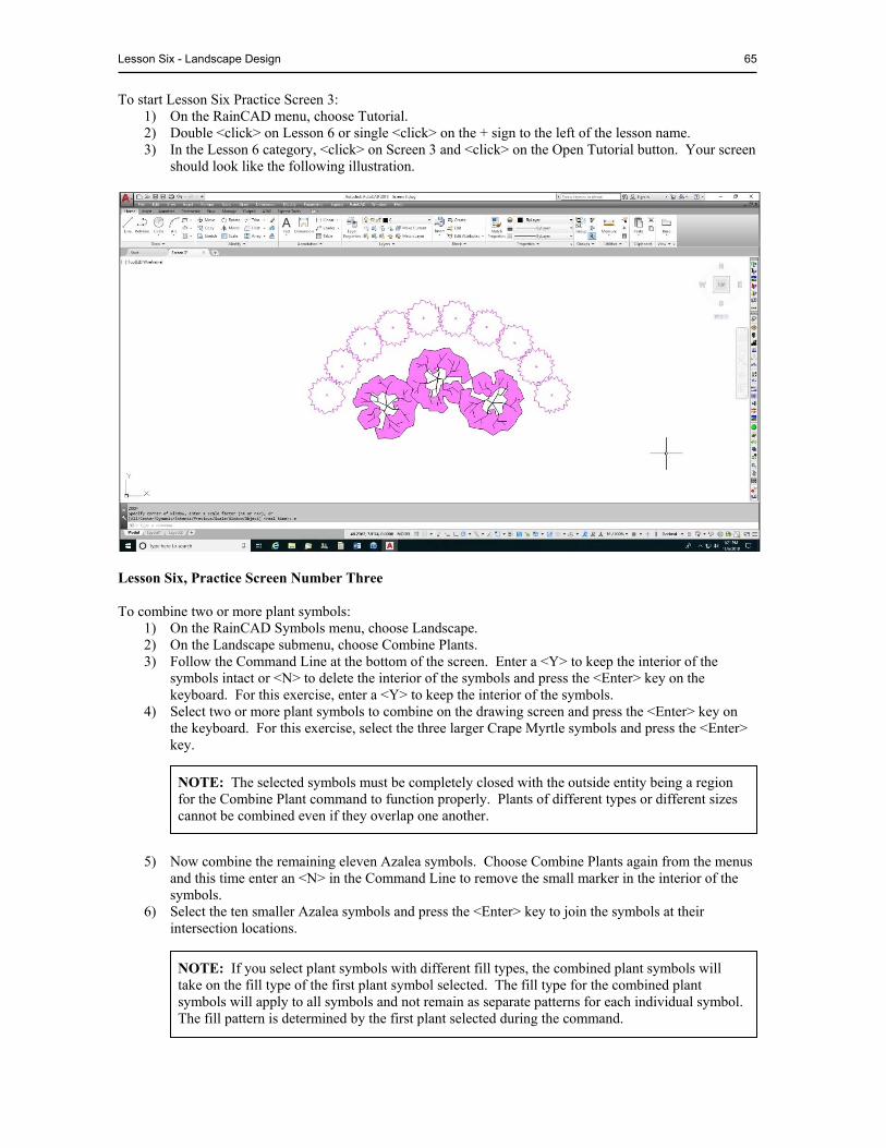
Lesson Six - Landscape Design 65
To start Lesson Six Practice Screen 3: 1) On the RainCAD menu, choose Tutorial. 2) Double <click> on Lesson 6 or single <click> on the + sign to the left of the lesson name. 3) In the Lesson 6 category, <click> on Screen 3 and <click> on the Open Tutorial button. Your screen
should look like the following illustration.
Lesson Six, Practice Screen Number Three To combine two or more plant symbols:
1) On the RainCAD Symbols menu, choose Landscape. 2) On the Landscape submenu, choose Combine Plants. 3) Follow the Command Line at the bottom of the screen. Enter a <Y> to keep the interior of the
symbols intact or <N> to delete the interior of the symbols and press the <Enter> key on the keyboard. For this exercise, enter a <Y> to keep the interior of the symbols.
4) Select two or more plant symbols to combine on the drawing screen and press the <Enter> key on the keyboard. For this exercise, select the three larger Crape Myrtle symbols and press the <Enter> key.
5) Now combine the remaining eleven Azalea symbols. Choose Combine Plants again from the menus and this time enter an <N> in the Command Line to remove the small marker in the interior of the symbols.
6) Select the ten smaller Azalea symbols and press the <Enter> key to join the symbols at their intersection locations.
NOTE: The selected symbols must be completely closed with the outside entity being a region for the Combine Plant command to function properly. Plants of different types or different sizes cannot be combined even if they overlap one another.
NOTE: If you select plant symbols with different fill types, the combined plant symbols will take on the fill type of the first plant symbol selected. The fill type for the combined plant symbols will apply to all symbols and not remain as separate patterns for each individual symbol. The fill pattern is determined by the first plant selected during the command.
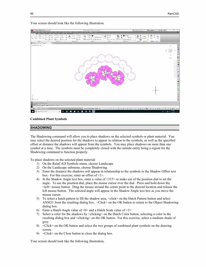
66 RainCAD
Your screen should look like the following illustration.
Combined Plant Symbols
SHADOWING
The Shadowing command will allow you to place shadows on the selected symbols or plant material. You may select the desired position for the shadows to appear in relation to the symbols, as well as the specified offset or distance the shadows will appear from the symbols. You may place shadows on more than one symbol at a time. The symbols must be completely closed with the outside entity being a region for the Shadowing command to function properly. To place shadows on the selected plant material:
1) On the RainCAD Symbols menu, choose Landscape. 2) On the Landscape submenu, choose Shadowing. 3) Enter the distance the shadows will appear in relationship to the symbols in the Shadow Offset text
box. For this exercise, enter an offset of <1>. 4) In the Shadow Angle text box, enter a value of <315> or make use of the position dial to set the
angle. To use the position dial, place the mouse cursor over the dial. Press and hold down the <left> mouse button. Drag the mouse around the center point to the desired location and release the left mouse button. The selected angle will appear in the Shadow Angle text box as you move the mouse cursor.
5) To select a hatch pattern to fill the shadow area, <click> on the Hatch Pattern button and select ANSI31 from the resulting dialog box. <Click> on the OK button to return to the Object Shadowing dialog box.
6) Enter a Hatch Angle value of <0> and a Hatch Scale value of <2>. 7) Select a color for the shadows by <clicking> on the Hatch Color button, selecting a color in the
resulting dialog box and <clicking> on the OK button. For this exercise, select a medium shade of grey.
8) <Click> on the OK button and select the two groups of combined plant symbols on the drawing screen.
9) <Click> on the Close button to close the dialog box. Your screen should look like the following illustration.
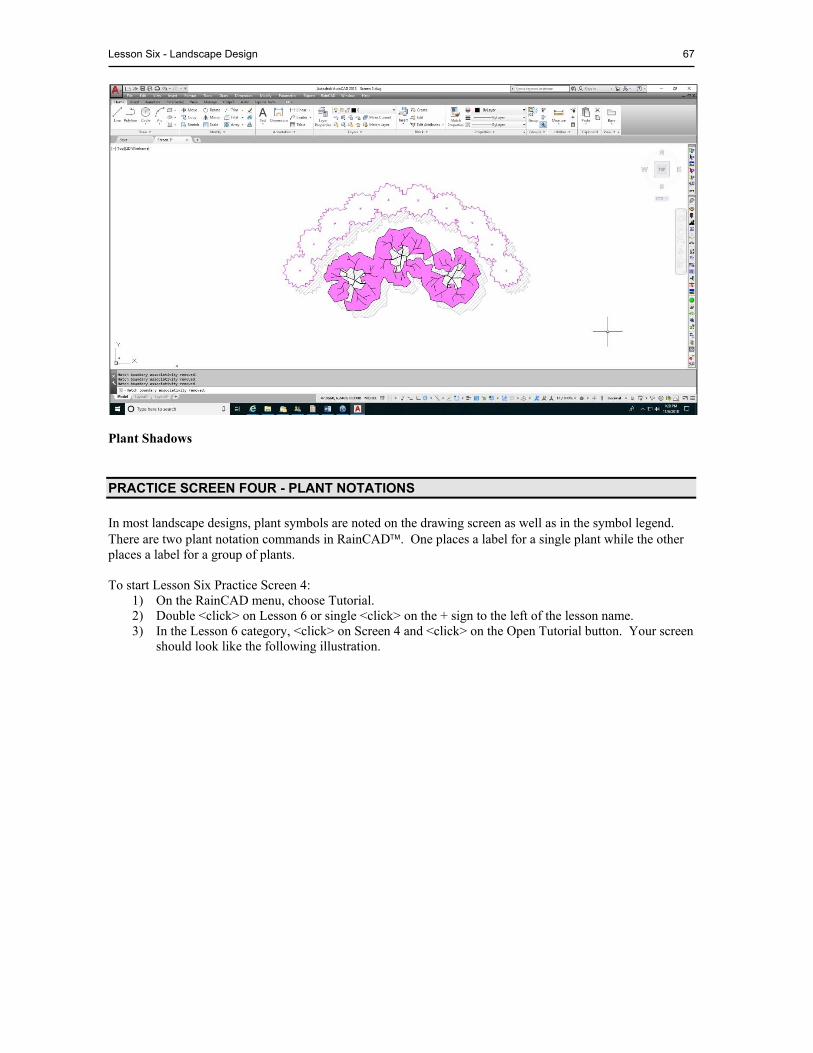
Lesson Six - Landscape Design 67
Plant Shadows
PRACTICE SCREEN FOUR - PLANT NOTATIONS
In most landscape designs, plant symbols are noted on the drawing screen as well as in the symbol legend. There are two plant notation commands in RainCAD. One places a label for a single plant while the other places a label for a group of plants. To start Lesson Six Practice Screen 4:
1) On the RainCAD menu, choose Tutorial. 2) Double <click> on Lesson 6 or single <click> on the + sign to the left of the lesson name. 3) In the Lesson 6 category, <click> on Screen 4 and <click> on the Open Tutorial button. Your screen
should look like the following illustration.
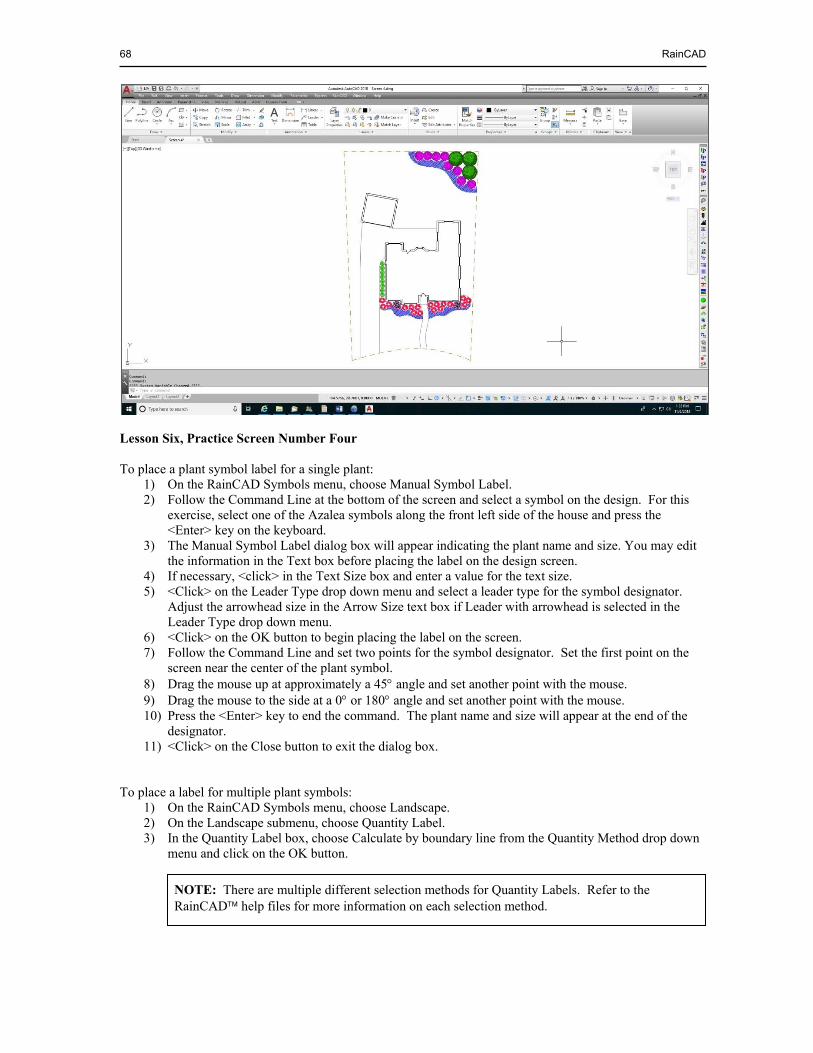
68 RainCAD
Lesson Six, Practice Screen Number Four To place a plant symbol label for a single plant:
1) On the RainCAD Symbols menu, choose Manual Symbol Label. 2) Follow the Command Line at the bottom of the screen and select a symbol on the design. For this
exercise, select one of the Azalea symbols along the front left side of the house and press the <Enter> key on the keyboard.
3) The Manual Symbol Label dialog box will appear indicating the plant name and size. You may edit the information in the Text box before placing the label on the design screen.
4) If necessary, <click> in the Text Size box and enter a value for the text size. 5) <Click> on the Leader Type drop down menu and select a leader type for the symbol designator.
Adjust the arrowhead size in the Arrow Size text box if Leader with arrowhead is selected in the Leader Type drop down menu.
6) <Click> on the OK button to begin placing the label on the screen. 7) Follow the Command Line and set two points for the symbol designator. Set the first point on the
screen near the center of the plant symbol. 8) Drag the mouse up at approximately a 45 angle and set another point with the mouse. 9) Drag the mouse to the side at a 0 or 180 angle and set another point with the mouse. 10) Press the <Enter> key to end the command. The plant name and size will appear at the end of the
designator. 11) <Click> on the Close button to exit the dialog box.
To place a label for multiple plant symbols:
1) On the RainCAD Symbols menu, choose Landscape. 2) On the Landscape submenu, choose Quantity Label. 3) In the Quantity Label box, choose Calculate by boundary line from the Quantity Method drop down
menu and click on the OK button.
NOTE: There are multiple different selection methods for Quantity Labels. Refer to the RainCAD help files for more information on each selection method.
Lesson Six - Landscape Design 69
4) Follow the Command Line at the bottom of the screen and select a plant symbol. For this exercise, select one of the Japanese Boxwood or Chinese Holly plant symbols on the left side of the house and press the <Enter> key on the keyboard.
5) Continue following the Command Line and outline the plants to include in the quantity label by drawing a polyline around the symbols. Set points with the left mouse button to outline the plant symbols on the left side of the house.
6) Once the area containing the plant material is outlined, press the <Enter> key on the keyboard. 7) The Quantity Label dialog box will appear indicating the quantity of plants, the plant name, and the
size. You may edit the information in the Text box before placing the label on the design screen. 8) If necessary, <click> in the Text Size box and enter a value for the text size. 9) <Click> on the Leader Type drop down menu and select a leader type for the symbol designator.
Adjust the arrowhead size in the Arrow Size text box if Leader with arrowhead is selected in the Leader Type drop down menu.
10) <Click> on the OK button to begin placing the label on the screen. 11) Follow the Command Line and set two points for the symbol designator. Set the first point on the
screen near the center of the plant symbol. 12) Drag the mouse up at approximately a 45° angle and set another point with the mouse. 13) Drag the mouse to the side at a 0° or 180° angle and set another point with the mouse. The quantity,
name, and size will appear at the end of the designator. To edit the text in a symbol label once it is on the design screen, you will need to make use of the AutoCAD Properties command. Refer to the AutoCAD help screens for more information on this command.
FILL MATERIALS
When creating a landscape design, you must be able to calculate area and volume. Before calculating volume, it is necessary to create a database of fill materials. To add a fill material to the database:
1) On the RainCAD Databases menu, choose Landscape. 2) On the Landscape submenu, choose Fill Material. 3) Double <click> on a Category Name with the left mouse button or single <click> on the + sign to
the left of the name to view the available fill materials. In addition, you can press the <right> mouse button to add, delete, or rename the fill material categories. For this exercise, open the Mulch category.
4) <Click> one time with the left mouse button on a fill material selection. Notice that the characteristics change based on the chosen material. In addition, you can press the <right> mouse button to add, delete, or rename the fill materials. For this exercise, add a new fill material to the list. A new item will be placed in the list with the title of New Fill Material.
5) <Click> on New Fill Material in the tree on the left side of the dialog box with the left mouse button. 6) Press the right mouse button and <click> on Rename. 7) Enter Bark Mulch as the new name in the box, and then press the <Enter> key. 8) You may assign a hatch pattern or gradient fill to represent the fill material on the design screen. In
addition, you can adjust color settings and more. If No Visible Fill is selected, no pattern will be used to represent the fill material
9) Enter a list price, discount rate, labor rate, and part number in the appropriate boxes as necessary. 10) For the software to correctly price the fill material, select the basis for pricing and installation from
the drop down menu. For this exercise, select Cubic Feet. 11) Once the information is entered into the database, <click> on the Save button to save the changes. 12) <Click> on the Close button to close the dialog box.
The software will allow you to calculate area/volume information and store the data for different locations within each drawing.
NOTE: The fill material selections are sorted based on the order in which they are entered.
70 RainCAD
To calculate area/volume information: 1) On the RainCAD Calcs menu, choose Landscape. 2) On the Landscape submenu, choose Area/Volume Calcs. 3) To add a new area to the list, place the mouse cursor in the tree on the left side of the dialog box.
Press the right mouse button and <click> on Manual Draw or Create from a Boundary Line. For this exercise, <click> on Manual Draw.
4) Follow the Command Line at the bottom of the screen and set three or more points to outline the area. Once the area is outlined, press the <Enter> key on the keyboard. A new item will be placed in the list with the title of New Fill Area. For this exercise, outline the flower bed on the front of the house to the right of the sidewalk.
5) <Click> on New Fill Area in the tree on the left side of the dialog box with the left mouse button. 6) Press the right mouse button and <click> on Rename. 7) Enter a description for the area such as Right Front Flowerbed and then press the <Enter> key. 8) Enter a value of <4> inches in the Depth of the fill material text box. 9) Select Bark Mulch from the Fill Material drop down menu. 10) <Click> on the Save button to save the calculations.
11) <Click> on the Close button to close the dialog box. When calculating a Material/Estimate, you may choose to list fill materials by each individual area or as a total sum per type of fill material.
MISCELLANEOUS SYMBOLS
The Miscellaneous symbols command allows you to create a list of symbols and place the miscellaneous symbols such as vehicles, stepping stones, and more on the drawing screen. Use these symbols to dress up a drawing and make it more meaningful or attractive to the end customer or prospect. Each symbol is an individual drawing file that must be stored in the \symbols\miscellaneous sub-directory on your computer. Refer to the RainCAD Help screens for information on adding symbols to the command. To place a miscellaneous symbol on the design screen:
1) On the RainCAD Symbols menu, choose Miscellaneous. 2) Double <click> on a Category with the left mouse button or single <click> on the + sign to the left
of the category name to view the available symbols. For this exercise, select the Furniture category.
3) <Click> one time with the left mouse button on a symbol. For this exercise, select Wooden Lawn Chairs.
4) <Click> on the OK button to place the symbol on the drawing screen. 5) Follow the Command Line at the bottom of the screen and set a point for the location of the symbol
by <clicking> one time with the left mouse button. Set a point in the backyard just outside of where the flowerbed curves inward.
6) Follow the Command Line again and set a second point to rotate the symbol at the desired angle. Set the second point at approximately a 45° angle up and to the left of the original point.
7) Press the <Close> to exit the dialog box.
NOTE: You can place the area/volume calculations on the design screen by <clicking> on the Insert Info button. Follow the Command Line and set an insertion point for the top left corner of the text. You can edit the text using the AutoCAD Multiline Text Editor.
NOTE: If Create from a Boundary Line is selected, follow the Command Line at the bottom of the screen. Select a single existing boundary line on the design screen and press the <Enter> key on the keyboard.
NOTE: The list of categories and file names are read straight from the directory and file structure as created in Windows Explorer. This allows the use of sub-folders to create sub-
Lesson Six - Landscape Design 71
AUTO SYMBOL LAYOUT
The Auto Symbol Layout command will allow you to automatically duplicate existing symbols at an even distance along an existing or temporary polyline. When using this command to duplicate symbols, you may select one or more symbols at a time. This command is helpful in duplicating stepping stones or other Miscellaneous Symbols. Create a stone pathway from the back patio to the wooden chairs in the backyard. Make use of the Miscellaneous Symbols command and place One Piece of Flagstone from the Stepping Stones category on the design screen anywhere in the backyard area. To place symbols automatically along a polyline:
1) On the RainCAD Symbols menu, choose Auto Symbol Layout. 2) To place the stepping stone symbol automatically along a temporary polyline on the drawing screen,
<click> on the Along a Temporary Polyline radio button. 3) Enter the offset in the Symbol Offset text box. For this exercise, enter a value of <0> in the offset
text box.
4) In the Symbol Rotation location, <click> on the down arrow to view a list of the rotation options. Select the Random rotation option from the resulting menu by <clicking> on the selection with the left mouse button.
5) <Click> on the OK button and follow the Command Line at the bottom of the screen. Select the One Piece of Flagstone symbol just placed with the Miscellaneous Symbols command and press <Enter>.
6) Set a point for the symbol handle. The handle is the rotation point for the symbol. <Click> one time on the center of the flagstone symbol with the left mouse button.
7) Continue to follow the Command Line and set two or more points for the temporary line and then press the <Enter> key on the keyboard. For this exercise, set multiple points to create a serpentine line from the back patio to the lawn chairs in the backyard. Once the points are set, press the <Enter> key to end the polyline.
8) Follow the Command Line and set a point on the side of the line on which the symbols will be placed. In this instance, the offset is set to zero so the stepping stone symbols will appear on top of the line.
9) A dialog box will appear allowing you to set the spacing for the symbols along the line. Enter the desired spacing for the symbols along the polyline in the Desired Spacing text box. For this exercise, enter a spacing of <3>.
10) To space the stepping stone symbols evenly along the polyline, select Even Spacing from the Spacing Type drop down menu by <clicking> on the selection one time with the left mouse button.
11) <Click> on the OK button to place the symbols automatically along the polyline
NOTE: The offset will allow you to place the symbols at a known distance to one side of the line or another. This feature may be used to offset symbols placed along an existing property line, fence or walkway. If the offset is set to zero (0), the symbols will appear directly on top of the polyline.
NOTE: The No rotation option will leave all copies of the symbol at the same rotation angle along the polyline. The Rotate along line option will rotate the copies of the symbol at the same angle as the polyline. The Random rotation option will randomly rotate the copies of the symbol along the polyline.
NOTE: The actual length of the line as well as the calculated spacing of the symbols will be displayed in the dialog box. To space the symbols evenly along the polyline, select Even Spacing from the Spacing Type drop down menu. To space the plant symbols at the exact spacing entered in the Desired Spacing text box, select Exact Spacing from the drop down menu.

72 RainCAD
12) <Click> on the Close button to close the Auto Symbol Layout dialog box. If the original stepping stone symbol is not used in the pathway, select the symbol and erase it from the design screen. Your drawing should now look similar to the following illustration.
Completed Auto Symbol Layout
LANDSCAPE INSTALLATION DETAILS
Installation details make the design easier for the installer to understand by indicating the precise method of installation. With small designs, which include most residential drawings, you may be able to place the installation details right on the drawing page. If this is a large commercial project, simply create a new drawing. The new drawing may consist of a title block, a legend, and installation details. To place a landscape installation detail on the drawing:
1) On the RainCAD Symbols menu, choose Installation Details. 2) On the Installation Details submenu, choose Landscape. 3) Double <click> on a Category with the left mouse button or single <click> on the + sign to the left
of the category name to view the available installation details. For this lesson, <click> on Trees in the list of category names.
4) <Click> one time with the left mouse button on Tree Guying and <click> on the OK button to place the installation detail on the drawing screen.
5) Follow the Command Line at the bottom of the screen and set a point for the detail location. For this exercise, set a point on the right side of the house outside of the property line.
6) Follow the Command Line and set a second point for the rotation angle of the detail. Set the second point directly to the right of the original point.
7) <Click> on the Close button to close the dialog box. To move or scale the detail symbol, make use of the AutoCAD Move and Scale commands.
NOTE: The list of categories and file names are read straight from the directory and file structure as created in Windows Explorer. This allows the use of sub-folders to create sub-
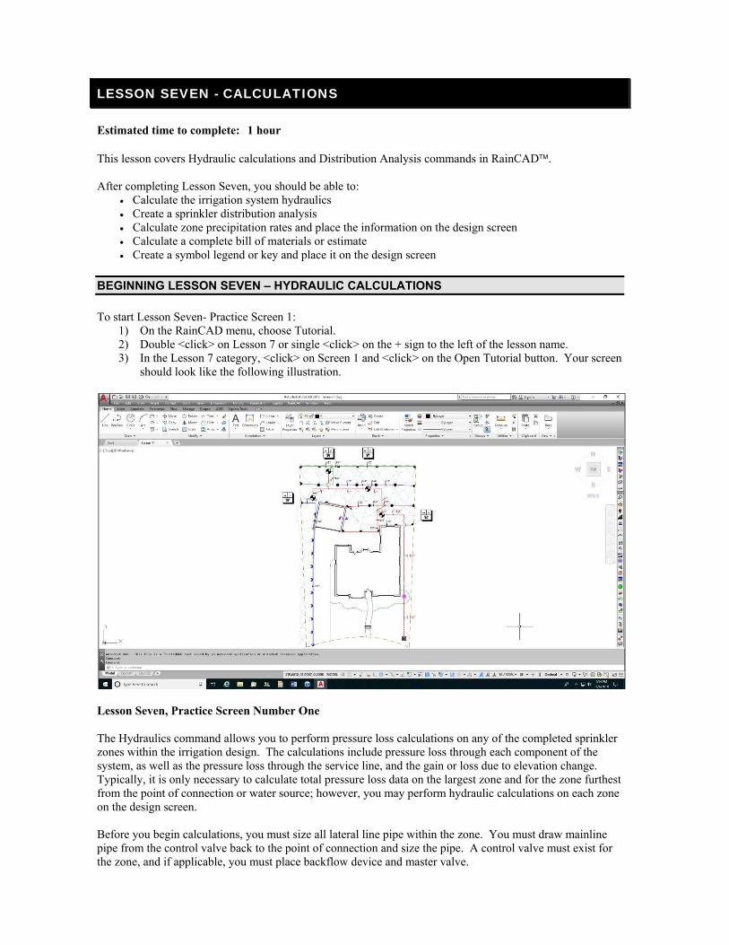
LESSON SEVEN - CALCULATIONS
Estimated time to complete: 1 hour This lesson covers Hydraulic calculations and Distribution Analysis commands in RainCAD. After completing Lesson Seven, you should be able to:
Calculate the irrigation system hydraulics Create a sprinkler distribution analysis Calculate zone precipitation rates and place the information on the design screen Calculate a complete bill of materials or estimate Create a symbol legend or key and place it on the design screen
BEGINNING LESSON SEVEN – HYDRAULIC CALCULATIONS
To start Lesson Seven- Practice Screen 1: 1) On the RainCAD menu, choose Tutorial. 2) Double <click> on Lesson 7 or single <click> on the + sign to the left of the lesson name. 3) In the Lesson 7 category, <click> on Screen 1 and <click> on the Open Tutorial button. Your screen
should look like the following illustration.
Lesson Seven, Practice Screen Number One The Hydraulics command allows you to perform pressure loss calculations on any of the completed sprinkler zones within the irrigation design. The calculations include pressure loss through each component of the system, as well as the pressure loss through the service line, and the gain or loss due to elevation change. Typically, it is only necessary to calculate total pressure loss data on the largest zone and for the zone furthest from the point of connection or water source; however, you may perform hydraulic calculations on each zone on the design screen. Before you begin calculations, you must size all lateral line pipe within the zone. You must draw mainline pipe from the control valve back to the point of connection and size the pipe. A control valve must exist for the zone, and if applicable, you must place backflow device and master valve.
74 RainCAD
You can calculate the hydraulics on each individual control valve. To run multiple valves at the same time, it is necessary for you to group the valves into individual Run Sets. Each Run Set is a group of control valves that will operate simultaneously. You may create as many different Run Sets as required. To add, delete, or assign a control valve to a run set, refer to the section on Automatic Mainline Pipe Sizing previously covered in this manual. To account for a change in elevation, make use of the AutoCAD® Properties command. Select one or more sprinkler, control valve, or water source symbols on the design screen. Once all necessary symbols are selected, enact the AutoCAD® Properties command and enter the elevation assignment in the Position Z box. On inline drip tubing zones, the hydraulic calculations include the loss through the control valve, the mainline, backflow, and water source. The hydraulic calculations on inline drip tubing zones does not include the loss in the tubing itself or the lateral line connecting the control valve to the tubing. To perform hydraulic calculations on a sprinkler zone:
1) On the RainCAD Calcs menu, choose Irrigation. 2) On the Irrigation submenu, choose Hydraulics. 3) In this exercise, you will calculate the hydraulics of a single control valve. Disable the Multiple
Valve Operation feature by <clicking> on selection with the left mouse button until the checkmark no longer appears in the box.
4) Select a control valve from the list on the left side of the dialog box. For this exercise, <click> on valve number 1-3 one time with the left mouse button.
5) To calculate the hydraulic information such as the pressure loss through the lateral line and mainline, the backflow device, water meter, and service line, <click> on the OK button.
Depending on the speed of the computer, the number of control valves, and the complexity of the piping layout, it will take a short period to calculate the system hydraulics for the selected control valve or Run Set. Once the system hydraulic calculations are complete, the Hydraulics Viewer will appear. The Hydraulics Viewer will allow you to select a piece of equipment on the screen and view more detailed information such as the size, length of pipe, flow, velocity, and pressure loss. To place the hydraulic information on the design screen:
1) On the Viewer tab, <click> on the Insert Summary On Drawing button to place a summary of the hydraulic calculations on the design screen.
2) Follow the Command Line and set an insertion point for the top left corner of the text.
To export the hydraulic information to an HTML file: 1) <Click> on the Detailed Report tab to view extensive information on all of the components within
the selected network. 2) <Click> on the Export Data to File button to save the information in an HTML format.
DISTRIBUTION
The Distribution command will create a densogram of the selected sprinkler zones displaying the coverage. You can drag the mouse around the entire display to see calculated application rate at any point in the sprinkler layout. The command will allow you to calculate the distribution of a single zone, multiple zones, or the entire project. The command reads the sprinkler layout from the design with no restrictions on sprinkler placement. The Distribution command will also calculate the Distribution Uniformity (DU), the Christiansen's Uniformity Coefficient (CU), and the Scheduling Coefficient (SC). The command will calculate the area of
NOTE: RainCAD will size mainline pipe in a loop network. There is no limit to the number of loops that may exist within the network. The loops may be totally independent of one another.
Lesson Seven – Calculations 75
each zone and the precipitation rate. You can place all of the information on the design screen in a table format. To calculate the distribution:
1) On the RainCAD Calcs menu, choose Irrigation. 2) On the Irrigation submenu, choose Distribution. 3) Select each water source or zone number to calculate by <clicking> on the checkbox to the left of
each Water Source / Zone ID number. <Click> on each selection with the left mouse button until a checkmark appears in the box. A zone that has not been selected will not be calculated. For this exercise, select all of the zones.
4) Enter a Watering Time Factor in the WTF% box next to each zone number. For this exercise, leave each of the zones at 100 percent.
5) Enable or disable the Blue Scale setting by <clicking> on the checkbox.
6) You may set the background color on the densogram to either white or black. <Click> on the Background Color drop down menu and <click> on the color selection one time with the left mouse button.
7) For the purpose of calculating the Distribution Uniformity (DU), in the DU From Lowest drop down menu, select either the lowest quarter (1/4) or lowest half (1/2). For this exercise, select 1/4.
8) For the purpose of calculating the Scheduling Coefficient (SC), in the SC Area %, enter a value between 1 and 10 in the text box or make use of the left and right arrow buttons. For this exercise, enter a value of <5>.
9) To determine the calculations from all of the selected sprinkler zones, in the Area Calculated From drop down menu, <click> on Checked Zones.
10) <Click> on the Calculate Distribution button to create a densogram of the selected sprinkler zones. The CU, DU, and SC will be displayed in the dialog box.
11) Drag your cursor over the densogram to display a reading of the application rate at any location throughout the selected zone(s).
NOTE: The Watering Time Factor Percentage is used to adjust the application rate for any of the selected zones. This factor is best used with sprinkler zones that do not make use of matched precipitation rate nozzles. For example, suppose all zones are based on the same nozzle having the same flow of 3.0 GPM. Zone 1 is made up of all 360° arc patterns. Zone 2 is all 180° patterns, while zone 3 is all 90° arc patterns. Zones 2 and 3 will appear to be over watered if you do not adjust the WTF. You can set zone 2 to 50 percent and zone 3 to 25 percent to match the application rate of the zones.
NOTE: If Blue Scale is disabled, the driest application areas appear in red, average application areas appear in blue, while the wettest areas appear in green. If Blue Scale is enabled, the driest areas will appear in white with the wettest areas appearing in the darkest shade of blue.
NOTE: You can select all of the zones at one time by pressing the <right> mouse button and <clicking> on Check All Zones in the resulting pop-up menu. If there are multiple water sources on a design and you would like to select just the zones assigned to one of the water sources, place the mouse cursor on a zone assigned to the desired water source and press the <right> mouse button. <Click> on Check All Zones for Water Source: X to select all of the zones assigned to that particular water source.
NOTE: To calculate from a more specific area, choose Temporary Polyline or Existing Polyline. If Temporary Polyline is selected, follow the Command Line and set three or more points to outline the area. If Existing Polyline is selected, follow the command line and select a polyline on the drawing screen.

76 RainCAD
12) <Click> on the Save button to save the image as a JPEG (*.jpg), Windows Bitmap (*.bmp), PNG (*.png), or TIFF (*.tiff) file. You may then open or import the bitmap image in another program such as Microsoft® Paint or Word for output to a printing device.
13) <Click> on the Insert Data On Drawing button to place the calculations on the drawing screen in a table format. Adjust the Text Style information as necessary and <click> on the OK button. Follow the Command Line at the bottom of the screen and set an insertion point on the screen. The insertion point will be the top left corner of the distribution table.
14) <Click> on the Close button to exit the dialog box.
PRACTICE SCREEN TWO - MATERIAL/ESTIMATE
The Material/Estimate command will allow you to calculate a complete bill of materials or create an estimate/proposal of installation costs for the current design. You may choose to calculate the material on the entire drawing, or in a selected area outlined with a Boundary Line. Pricing information and labor for installation may be entered in each of the databases available for equipment and materials. You may select each field to appear in the report and adjust the order in which they appear. Once the calculations are complete, you may view the information on the screen, send it to the printer, or export the information to one of many different file formats. File formats include Microsoft® Excel, Lotus 1-2-3, Word for Windows™, Adobe Acrobat, HTML, XML, ASCII Text and more. On the Report Style tab on the Material/Estimate Configuration dialog box you can adjust the paper orientation and size, the report font style, insert a company logo, and adjust header and text colors. Before you create a report, you may change the labels that appear on the report from the Options command in the Options/Info menu in RainCAD. This feature is especially useful if the report is to be output to a foreign language. You may include your company information such as the name, address, and phone numbers at the top of a report. To include this information, you must enter your company information in the Company Information database from the Databases menu in RainCAD. To start Lesson Seven Practice Screen 2:
1) On the RainCAD menu, choose Tutorial. 2) Double <click> on Lesson 7 or single <click> on the + sign to the left of the lesson name. 3) In the Lesson 7 category, <click> on Screen 2 and <click> on the Open Tutorial button. Your screen
should look like the following illustration.
NOTE: The command reads the Distribution Data for each sprinkler from the Distribution Data tab in the Sprinklers Database. If data does not exist for the sprinkler, the distribution pattern of each sprinkler is assumed to be even over the entire radius of the sprinkler. In instances where actual distribution data does not exist for each nozzle, the distribution will not be totally accurate, but will serve as a good guideline for potential wet and dry areas within the design.
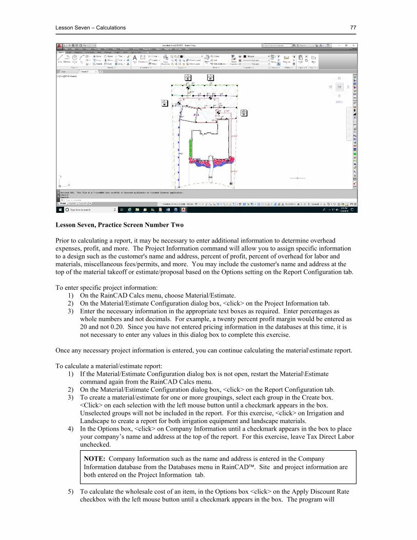
Lesson Seven – Calculations 77
Lesson Seven, Practice Screen Number Two Prior to calculating a report, it may be necessary to enter additional information to determine overhead expenses, profit, and more. The Project Information command will allow you to assign specific information to a design such as the customer's name and address, percent of profit, percent of overhead for labor and materials, miscellaneous fees/permits, and more. You may include the customer's name and address at the top of the material takeoff or estimate/proposal based on the Options setting on the Report Configuration tab. To enter specific project information:
1) On the RainCAD Calcs menu, choose Material/Estimate. 2) On the Material/Estimate Configuration dialog box, <click> on the Project Information tab. 3) Enter the necessary information in the appropriate text boxes as required. Enter percentages as
whole numbers and not decimals. For example, a twenty percent profit margin would be entered as 20 and not 0.20. Since you have not entered pricing information in the databases at this time, it is not necessary to enter any values in this dialog box to complete this exercise.
Once any necessary project information is entered, you can continue calculating the material\estimate report. To calculate a material/estimate report:
1) If the Material/Estimate Configuration dialog box is not open, restart the Material\Estimate command again from the RainCAD Calcs menu.
2) On the Material/Estimate Configuration dialog box, <click> on the Report Configuration tab. 3) To create a material/estimate for one or more groupings, select each group in the Create box.
<Click> on each selection with the left mouse button until a checkmark appears in the box. Unselected groups will not be included in the report. For this exercise, <click> on Irrigation and Landscape to create a report for both irrigation equipment and landscape materials.
4) In the Options box, <click> on Company Information until a checkmark appears in the box to place your company’s name and address at the top of the report. For this exercise, leave Tax Direct Labor unchecked.
5) To calculate the wholesale cost of an item, in the Options box <click> on the Apply Discount Rate checkbox with the left mouse button until a checkmark appears in the box. The program will
NOTE: Company Information such as the name and address is entered in the Company Information database from the Databases menu in RainCAD. Site and project information are both entered on the Project Information tab.
78 RainCAD
calculate the wholesale cost based on the List Price and Discount Rate set for each item in the databases. If a checkmark does not appear in the box, the program will not apply the discount rate to the list price of each item. For this exercise, leave Apply Discount Rate unchecked.
6) For landscape calculations, you can list fill materials by area or as one total sum per each type of material. To list fill material items by each individual area, <click> on the Fill Material by Area checkbox with the left mouse button until a checkmark appears in the box. To display fill materials as a total sum per each type, <click> on the checkbox until the checkmark is removed. For this exercise, leave List Fill Materials by Area unchecked.
7) You may calculate the material list for the entire drawing or from a selected area of the drawing outlined by a Boundary Line. In the Report Type location, <click> on the down arrow to view a list of the available selections. Select an option from the resulting menu by <clicking> on the selection with the left mouse button. This selection does not apply to fill materials. The fill material for the entire drawing will be displayed no matter what selection is chosen. For this lesson, leave the Report Type set to Calculate from Entire Drawing.
8) In the Fittings Calculation location, <click> on the down arrow to view a list of the available selections. Select a method of calculating irrigation fittings from the resulting menu by <clicking> on the selection with the left mouse button. If Calculate as a Percent of Pipe is chosen, enter a percent of pipe cost in the % of Pipe text box. For example, enter a percent of pipe cost of 15 percent as 15.00 and not 0.15. The percentage is based on a percent of the List Price for the pipe. For this exercise, set the fitting type to Calculate from Drawing.
9) The fields available to appear in the Material/Estimate Report are shown in the Report Field Configuration listing. The fields are displayed in the order in which they will appear on the report. You may adjust the order by <clicking> on a field name and <clicking> on the up or down arrow buttons. To remove a field from the report, <click> on the checkbox to the left of the field name until the checkmark no longer appears in the box.
10) <Click> on the Calculate Report button to create the report, or <click> on the Recalculate Report if adjustments have been made to the design.
11) <Click> on the View Material Estimate button to preview the quantity and description of all items in the report, or <click> on the View Estimate/Proposal button to the view the pricing information.
Once you calculate a material takeoff or estimate/proposal, you may adjust the settings and click on one of the View buttons to preview the report. You will not need to calculate the report again unless you make changes to the design itself. The material list is saved in a Microsoft® Access database file. The file has the same name as the drawing except for an mdb extension. From within the Material/Estimate Preview command, you may send a report to the printer or export the information to one of many different file formats. File formats include Microsoft® Excel, Lotus 1-2-3, Word for Windows™, Adobe Acrobat, HTML, XML, ASCII Text, and more. In addition, you may zoom in or out, change from one page within the report to another, and search for items in the report. To view the estimate/proposal report:
1) If the Material/Estimate Configuration dialog box is not open, restart the Material\Estimate command again from the RainCAD Calcs menu.
2) On the Material/Estimate Configuration dialog box, <click> on the Report Configuration tab. 3) After calculating the report, <click> on the View Estimate/Proposal button to preview the report. 4) <Click> on the X in the top right corner of the dialog box to close the viewer. 5) <Click> on the Close button to close the Material/Estimate Configuration dialog box.
NOTE: <Clicking> on the Material Takeoff Report button will only display the Quantity and Description for each item no matter what fields are selected in the Report Field Configuration. The selected fields will only be displayed when <clicking> on the View Estimate/Proposal button.
Lesson Seven – Calculations 79
LEGENDS
The Legend command will create a legend of all equipment and materials that appear on the design. The legend may include irrigation, landscape, lighting, and drainage equipment depending on the version of the software you are running. To create a legend and place it on the design screen:
1) If Lesson Seven, Screen 2 is not open, reopen the drawing. 2) On the RainCAD Symbols menu, choose Create Legend. 3) Select each category to include in the legend in the Create box. <Click> on each selection with the
left mouse button until a checkmark appears in the box. For this exercise, select Irrigation and Landscape.
4) In the Legend Text Style location, select the font or text style for the legend by <clicking> on the drop down menu and <clicking> on the desired selection one time with the left mouse button. Set the desired text size in the Text Size box. Select a Default Color for Legend by <clicking> on the colored rectangle one time with the left mouse button to open the Color dialog box. Select a color and <click> on the OK button. For this exercise, set the text style to Arial, the text size to <1.5>, and leave the color set to ByLayer.
5) Leave the desired column factor set to 1 in the Column Factor text box. A number less than one will bring the columns closer together while a number greater than one will spread the columns further apart.
6) To place a grid around the legend, click on Show Grid with the left mouse button until a checkmark appears in the box.
7) If you include landscape materials in the legend, you may adjust the Plant Symbol Size. radius setting. Select Relative to drawing from the drop down menu to set the symbols relative to the symbol sizes on the design screen. Select Custom to enter a value for the radius of all plant symbols placed on the legend in the Custom text box. For this exercise, select Relative from the drop down menu.
8) To include the Plant Abbreviation for landscape materials in the legend, <click> on the Show Plant Abbreviations check box with the left mouse button until a checkmark appears in the box. If the checkbox is disabled, the plant abbreviations will not appear in the legend.
9) <Click> on the Calculate button to evaluate the design and determine all of the items required to appear in the legend.
10) <Click> on the Place button to insert the legend onto the drawing. Follow the Command Line at the bottom of the screen and set a starting point for the legend. The starting point will be the top left position of the legend.
11) Once the legend appears on the screen, <click> on the Close button to exit the dialog box.
NOTE: When creating a symbol Legend, you can have the plant material name appear as the Common Name, Botanical Name, or the Common Name and Botanical Name based on the Name Display Type setting in the Landscape Preferences dialog box.

80 RainCAD
This page is intentionally left blank.
LESSON EIGHT - MODIFYING THE DATABASES
Lesson Eight does not have any accompanying practice screens. This lesson will instruct you on modifying the existing databases of equipment or landscape materials. All of the databases are similar in the way they function. Some databases have options that do not exist in other databases. However, once you become familiar with one database, you should be able to work in any of the database selections. When you place equipment or plant material on a drawing, the information in the database is used to identify each piece of equipment or plant material and price it correctly. Database characteristics that are common to virtually all of the database selections are list price, discount rate, labor rate, equipment code, part number, and supplier code. Most databases also include the description, symbol assignment, symbol color, and tied assembly.
THE SPRINKLERS DATABASE
The Sprinklers Database will allow you to edit a database of sprinkler nozzle selections based on the chosen manufacturer and the selected category. The sprinklers are shown in eight different categories - Turf Sprays, Shrub Sprays, Shrub Risers, Turf Rotors, Shrub Rotors, Bubblers, Low-Volume, and Golf. To edit the sprinkler databases:
1) On the RainCAD Databases menu, choose Irrigation. 2) On the Irrigation submenu, choose Sprinklers. 3) Double <click> on a Manufacturer with the left mouse button or single <click> on the + sign to the
left of the manufacturers name to view the available sprinkler nozzle categories. 4) Double <click> on a Category Name with the left mouse button or single <click> on the + sign to
the left of the category name to view the available sprinkler nozzles. 5) Choose a sprinkler nozzle from the list by <clicking> on the selection with the mouse. Notice that
the characteristics change based on the chosen sprinkler nozzle. Once you select the desired nozzle, you may modify any of the characteristics as necessary. Characteristics specific to the Sprinklers Database include the arc pattern assignment, the performance characteristics, the default pressure setting, and the sprinkler body assignment.
ADDING A SPRINKLER TO THE DATABASE
When adding equipment to a database, it is important that you enter the equipment in the order you would like it displayed in the dialog box. For example, it would be best to group all fifteen-foot spray nozzles together and all twelve-foot spray nozzles together. This will make it easier to find the correct equipment for placement on the drawing screen. To add a sprinkler to the sprinklers database:
1) On the RainCAD Databases menu, choose Irrigation. 2) On the Irrigation submenu, choose Sprinklers. 3) Double <click> on a Manufacturer with the left mouse button or single <click> on the + sign to the
left of the manufacturers name to view the available sprinkler nozzle categories. 4) Double <click> on a Category Name with the left mouse button or single <click> on the + sign to
the left of the category name to view the available sprinkler nozzles. 5) Press the right mouse button and <click> on Add Sprinkler to add a new sprinkler to the list. The
new sprinkler will appear at the bottom of the list. 6) <Click> on New Sprinkler in the list and press the right mouse button. 7) <Click> on Rename and enter a description for the sprinkler. 8) Edit each characteristic as necessary and click on the <Save> button to save the information.
NOTE: You cannot change the order of the equipment once you enter it into the database.

82 RainCAD
PERFORMANCE DATA
To make use of a sprinkler in the design process, it is necessary to enter the performance characteristics of the nozzle. With each operating pressure, you must enter the flow of water through the nozzle and the radius of the throw. To edit the performance characteristics of the selected sprinkler:
1) On the RainCAD Databases menu, choose Irrigation. 2) On the Irrigation submenu, choose Sprinklers. 3) Double <click> on a Manufacturer with the left mouse button or single <click> on the + sign to the
left of the manufacturers name to view the available sprinkler nozzle categories. 4) Double <click> on a Category Name with the left mouse button or single <click> on the + sign to
the left of the category name to view the available sprinkler nozzles. 5) Choose a sprinkler nozzle from the list by <clicking> on the selection with the left mouse button. 6) In the Performance area on the Equipment Data tab, <click> into a data box one time with the left
mouse button to modify the performance information. You can add data to the table by <clicking> on the Add button to right of the Performance label. You can delete the selected Default Pressure data by selecting a pressure setting from the drop down menu and <clicking> on the Delete button.
7) In the Performance data location, enter the operating pressure, flow, and radius of throw in the available text boxes. If the nozzle is assigned to a side strip, end strip, center strip, or square arc pattern, you must enter the width of the throw as well.
8) You must also assign a Default Pressure setting for each nozzle in the Performance data location.
<Click> on the drop down menu to the right of the Default Pressure label and <click> one time on the desired selection. This is the performance information that will be associated with the nozzle when it is placed on the design screen and when pipe sizing and system hydraulic calculations are performed.
9) Once all entries are made, <click> on the Save button to save the additions or changes to the Performance data.
DISTRIBUTION DATA
If distribution information is available for the nozzle, you may enter precipitation rate information at known intervals to create a distribution chart. If no data is entered for the sprinkler, the software assumes a perfect distribution pattern. This information is used when creating a densogram of potential wet and dry areas in the design with the Distribution command. To edit the distribution data of the selected sprinkler:
1) On the RainCAD Databases menu, choose Irrigation. 2) On the Irrigation submenu, choose Sprinklers. 3) <Click> on the Distribution Data tab. 4) Double <click> on a Manufacturer with the left mouse button or single <click> on the + sign to the
left of the manufacturers name to view the available sprinkler nozzle categories. 5) Double <click> on a Category Name with the left mouse button or single <click> on the + sign to
the left of the category name to view the available sprinkler nozzles. 6) Choose a sprinkler nozzle from the list by <clicking> on the selection with the left mouse button. 7) To enter information in the Distribution Data table, you must first select a pressure setting. <Click>
on the drop down menu to the right of the Pressure label and <click> one time on the desired selection. You may then enter precipitation rate information at known intervals in the Distribution data table.
NOTE: When entering performance characteristics, begin with the lowest pressure. For example, the first pressure you enter may be 15 PSI. The next pressure may be 20 followed by 25, 30, 35, and 40. We recommend that you follow this same rule when entering performance data for control valves and backflow devices as well.
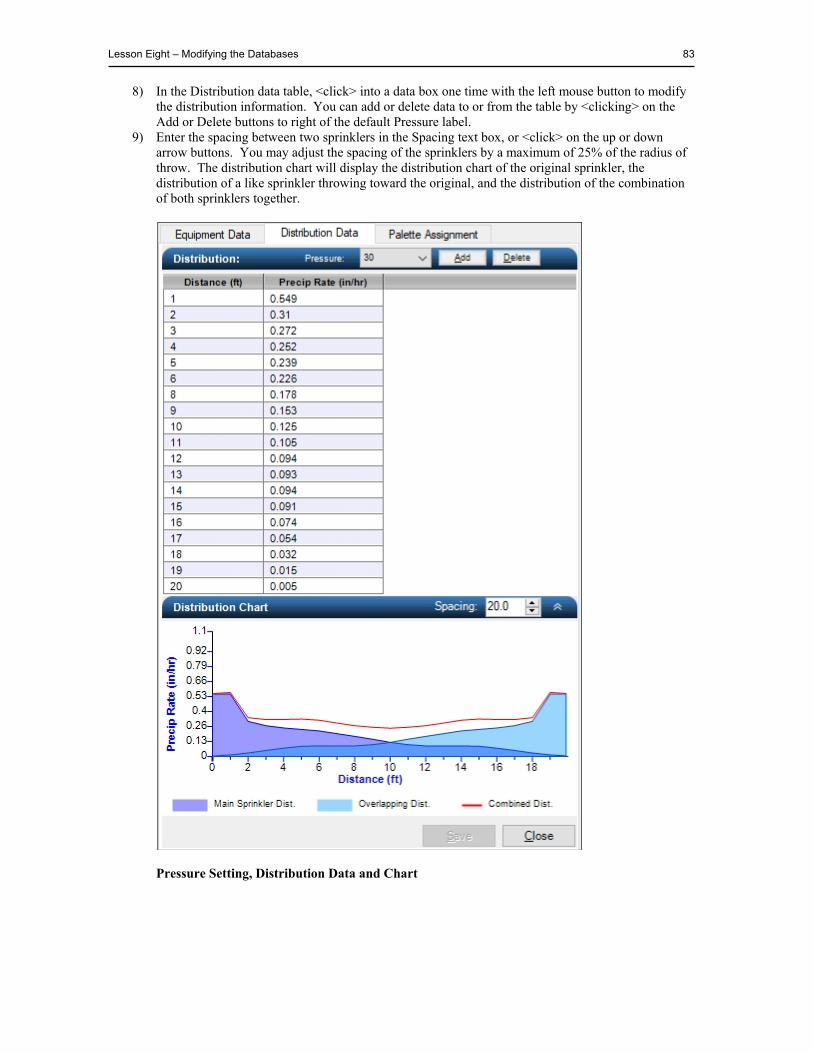
Lesson Eight – Modifying the Databases 83
8) In the Distribution data table, <click> into a data box one time with the left mouse button to modify the distribution information. You can add or delete data to or from the table by <clicking> on the Add or Delete buttons to right of the default Pressure label.
9) Enter the spacing between two sprinklers in the Spacing text box, or <click> on the up or down arrow buttons. You may adjust the spacing of the sprinklers by a maximum of 25% of the radius of throw. The distribution chart will display the distribution chart of the original sprinkler, the distribution of a like sprinkler throwing toward the original, and the distribution of the combination of both sprinklers together.
Pressure Setting, Distribution Data and Chart
84 RainCAD
SPRINKLER PALETTE ASSIGNMENTS
Each manufacturer has possibly hundreds of different sprinkler nozzle selections. When placing sprinklers automatically within a boundary line, you will only need to make use of a few nozzle selections. Just as an artist has millions of colors to choose from when he begins a painting, he only makes use of a few colors that he places on his palette. A sprinkler palette is similar to an artist’s color palette. A Sprinkler Palette is a group of sprinklers to use in a particular situation. For example, you may create a palette of nozzles consisting of only 15 foot sprays. In addition, you may have another palette consisting of 8 foot or 10 foot nozzles. You may create separate palettes for turf sprays, shrub sprays, turf rotors and shrub rotors. You may create as many sprinkler palettes as required for each manufacturer and each sprinkler category. In addition, you may assign each sprinkler to one or more sprinkler palettes. To assign a sprinkler to a sprinkler palette:
1) On the RainCAD Databases menu, choose Irrigation. 2) On the Irrigation submenu, choose Sprinklers. 3) On the Sprinklers dialog box, <click> on the Palette Assignments tab. 4) Double <click> on a Manufacturer with the left mouse button or single <click> on the + sign to the
left of the manufacturers name to view the available sprinkler nozzle categories. 5) Double <click> on a Category Name with the left mouse button or single <click> on the + sign to
the left of the category name to view the available sprinkler palettes associated with the selected category on the right side of the dialog box.
6) <Click> on the Add button to the right of the Palettes label to add a new sprinkler palette. <Click> on the palette name two times with the left mouse button to rename the palette. <Click> on the Delete button to remove the palette from the list.
7) Double <click> on a sprinkler palette name with the left mouse button or single <click> on the + sign to the left of the palette name. All of the sprinklers currently assigned to the selected sprinkler palette are shown below the palette name. All of the sprinklers available for assignment are shown under the sprinkler category name on the left side of the dialog box.
8) To assign a sprinkler nozzle to the selected palette, <click> on the nozzle in the Sprinklers list and <click> on the right arrow button, or double <click> on the sprinkler nozzle. The nozzle will be placed under the Sprinkler Palette Assignments.
9) To remove a nozzle from a palette, <click> on the nozzle in the Sprinkler Palette Assignments list and <click> on the left arrow button, or double <click> on the sprinkler nozzle.
10) <Click> on the Close button to exit the command and save the changes.
The remaining irrigation databases all function very similar to the Sprinklers Database. For additional help on databases, refer to the Help screens in RainCAD.
TIED ASSEMBLIES AND SUPPLIES
A Tied Assembly is the combination of supplies that are associated with the installation of a single piece of equipment or plant material. Tied assemblies can be built for sprinkler bodies, controllers, backflow devices, control valves, trees, shrubs, and more.
NOTE: All sprinkler palettes must include at least one nozzle with an arc assignment of 180º. If a palette does not have a 180º nozzle assignment, you will not be able to make use of that palette in the automatic sprinkler placement within a boundary line. Sprinkler palettes cannot include specialty nozzles such as side strips or end strips.
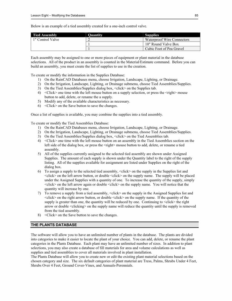
Lesson Eight – Modifying the Databases 85
Below is an example of a tied assembly created for a one-inch control valve.
Tied Assembly Quantity Supplies 1" Control Valve 2 Waterproof Wire Connectors
1 10" Round Valve Box 1 Cubic Foot of Pea Gravel
Each assembly may be assigned to one or more pieces of equipment or plant material in the database selections. All of the product in an assembly is counted in the Material/Estimate command. Before you can build an assembly, you must create the list of supplies to use in the creation. To create or modify the information in the Supplies Database:
1) On the RainCAD Databases menu, choose Irrigation, Landscape, Lighting, or Drainage. 2) On the Irrigation, Landscape, Lighting, or Drainage submenu, choose Tied Assemblies/Supplies. 3) On the Tied Assemblies/Supplies dialog box, <click> on the Supplies tab. 4) <Click> one time with the left mouse button on a supply selection, or press the <right> mouse
button to add, delete, or rename the a supply. 5) Modify any of the available characteristics as necessary. 6) <Click> on the Save button to save the changes.
Once a list of supplies is available, you may combine the supplies into a tied assembly. To create or modify the Tied Assemblies Database:
1) On the RainCAD Databases menu, choose Irrigation, Landscape, Lighting, or Drainage. 2) On the Irrigation, Landscape, Lighting, or Drainage submenu, choose Tied Assemblies/Supplies. 3) On the Tied Assemblies/Supplies dialog box, <click> on the Tied Assemblies tab. 4) <Click> one time with the left mouse button on an assembly in the Tied Assemblies section on the
left side of the dialog box, or press the <right> mouse button to add, delete, or rename a tied assembly.
5) All of the supplies currently assigned to the selected tied assembly are shown under Assigned Supplies. The amount of each supply is shown under the Quantity label to the right of the supply listing. All of the supplies available for assignment are listed under Supplies on the right of the dialog box.
6) To assign a supply to the selected tied assembly, <click> on the supply in the Supplies list and <click> on the left arrow button, or double <click> on the supply name. The supply will be placed under the Assigned Supplies with a quantity of one. To increase the quantity of the supply, simply <click> on the left arrow again or double <click> on the supply name. You will notice that the quantity will increase by one.
7) To remove a supply from a tied assembly, <click> on the supply in the Assigned Supplies list and <click> on the right arrow button, or double <click> on the supply name. If the quantity of the supply is greater than one, the quantity will be reduced by one. Continuing to <click> the right arrow or double <clicking> on the supply name will reduce the quantity until the supply is removed from the tied assembly.
8) <Click> on the Save button to save the changes.
THE PLANTS DATABASE
The software will allow you to have an unlimited number of plants in the database. The plants are divided into categories to make it easier to locate the plant of your choice. You can add, delete, or rename the plant categories in the Plants Database. Each plant may have an unlimited number of sizes. In addition to plant selections, you may also create a database of fill materials for area and volume calculations as well as supplies and tied assemblies to cover all materials involved in plant installation. The Plants Database will allow you to create new or edit the existing plant material selections based on the chosen category and size. The six default categories of plant material are Tress, Palms, Shrubs Under 4 Feet, Shrubs Over 4 Feet, Ground Cover-Vines, and Annuals-Perennials.
86 RainCAD
ADDING A PLANT TO THE DATABASE
When adding plant material to the database, you may enter the information in any order. The plant selections are sorted alphabetically based on the common or botanical name as set in the Landscape Preferences dialog box. To add a plant to the database:
1) On the RainCAD Databases menu, choose Landscape. 2) On the Landscape submenu, choose Plants. 3) On the Plant Database dialog box, <click> on the General Plant Data tab. 4) Double <click> on a Category Name with the left mouse button or single <click> on the + sign to
the left of the name to view the available plant selections. In addition, you can press the <right> mouse button to add, delete, or rename the plant category names.
5) Press the <right> mouse button and <click> on Add Plant to place a new plant selection in the list. The New Plant listing will appear at the bottom of the list of plant names.
6) Scroll down to the New Plant selection at the bottom of the list of plant names. 7) <Click> on New Plant in the list and press the <right> mouse button. 8) <Click> on Rename and enter a description for the Common Name. 9) <Click> in the Botanical Name text box and enter a description. 10) You may assign an image to the selected plant material. In the Plant Image area, enter the complete
path to the image file in the Image Path text box, or <click> on the Open icon to locate the image file on your computer.
11) Modify the general notes in the General Description text box as necessary. The general notes for the plant may be unlimited in length.
12) <Click> on the Save button to save the changes.
PLANT SIZE DATA
The Plant Size Data feature will allow you to enter or edit information on the plant material such as the available sizes, the symbol assignment, and the symbol color. When plants are placed on a design and counted in a material takeoff, it is this information that is used to identify them and price them correctly. To enter or edit the plant size data:
1) On the RainCAD Databases menu, choose Landscape. 2) On the Landscape submenu, choose Plants. 3) On the Plant Database dialog box, <click> on the Plant Size Data tab. 4) Double <click> on a Category Name with the left mouse button or single <click> on the + sign to
the left of the name to view the available plant selections. In addition, you can press the <right> mouse button to add, delete, or rename the plant category names.
5) <Click> one time with the left mouse button on a plant selection. Notice that the characteristics change based on the chosen plant. In addition, you can press the <right> mouse button to add, delete, or rename the plants. The plant selections are sorted alphabetically based on the common or botanical name as set in the Landscape Preferences dialog box.
Once you select a plant, you may modify any of the characteristics as necessary. Plant characteristics include the symbol assignment, the symbol color, the radius of the plant’s canopy, the list price, a discount received from the supplier, the labor rate for installation, and more. To modify the plant characteristics:
1) Select a plant size from the Plant Size drop down menu by <clicking> on the selection one time with the left mouse button. If necessary, <click> on the Add button to add a new plant size to the list. In the resulting dialog box, enter a new plant size name such as 1 gallon or 24 inch box and <click> on the OK button.
Lesson Eight – Modifying the Databases 87
2) Before a plant may be placed on a design, you must assign a symbol or hatch pattern to represent the plant material. In addition, you can set a fill type, color settings and more. You may assign separate symbol settings for each different size associated with the plant material, or you can have the same symbol settings for each different size.
3) Once a plant size is selected, choose the type of symbol you will use to represent the plant material on the design screen from the Symbol Type drop down menu. Choose Symbol if you plan to assign an individual symbol number to represent the plant material. Choose Hatch if you plan to assign an AutoCAD® hatching pattern or gradient fill to represent the plant material.
4) If Symbol is chosen as the Symbol Type, enter the symbol assignment in the Symbol text box, or <click> on the drop down arrow to locate the symbol in the Symbol Browser dialog box. <Click> on the desired symbol to accept the assignment.
5) Enter the marker type number in the Marker/Interior box, or <click> on the drop down arrow to locate the marker in the Browser dialog box. <Click> on the desired marker to accept the assignment. If you do not want to add a marker to the selected symbol, choose the marker labeled None.
6) If Symbol is chosen as the Symbol Type, select a symbol color assignment. <Click> on the colored rectangle to the right of the Symbol Color label one time with the <left> mouse button. In the Color dialog box, select a color and <click> on the OK button.
7) If Symbol is chosen as the Symbol Type, enter the radius of the plant canopy in the Radius text box.
8) Adding a Sketch Factor to a symbol may give it a more hand drawn appearance. The sketch factor randomly adds lines to the symbol at slightly different angles. To use the symbol as originally drawn without a sketch factor, select None from the drop down menu. To add a sketch factor to a symbol, <click> on Low, Medium or High from the drop down menu.
NOTE: Hatching patterns best represent small plant material planted in large quantities such as ground cover or annual color.
NOTE: To place a plant on the drawing screen, the radius of the plant’s canopy must be set to a value greater than zero. You may assign each plant size a different radius setting. It is important that you enter a value for each plant size you plan to include on the design.
NOTE: Each characteristic on the Plant Size Data tab is specific to the size of the selected plant where species data and general information is generic to all sizes. For example, the radius of the plant canopy, the list price, and the labor rate for installation are all plant characteristics. These factors may change based on the size of the plant. If a plant is a 1 gallon versus a 15 gallon, the radius may be smaller and the labor rate for installation may be less. The color of the plant, the mature height and the exposure are all species data. This data will remain the same no matter what size the plant is at installation. To assign the same symbol settings to each of the plant sizes, <click> on the Apply To All Plant Sizes check box to the right of the Symbol Settings label until a checkmark appears in the box.
NOTE: If a checkmark appears in the Show All Symbols box, you will see all of the available plant symbols. If the check box is disabled, you will only see the symbols marked as exteriors with an ext prefix. Combining exterior symbols with Marker/Interiors allows for a large number of symbol combinations.
NOTE: Adding a sketch factor to a plant symbol can affect the ability to trim symbols at their intersections with the Combine Plants command.
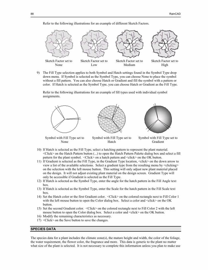
88 RainCAD
Refer to the following illustrations for an example of different Sketch Factors.
Sketch Factor set to
NoneSketch Factor set to
LowSketch Factor set to
MediumSketch Factor set to
High 9) The Fill Type selection applies to both Symbol and Hatch settings found in the Symbol Type drop
down menu. If Symbol is selected as the Symbol Type, you can choose None to place the symbol without a fill pattern. You can also choose Hatch or Gradient and fill the symbol with a pattern or color. If Hatch is selected as the Symbol Type, you can choose Hatch or Gradient as the Fill Type.
Refer to the following illustrations for an example of fill types used with individual symbol assignments.
Symbol with Fill Type set to
None Symbol with Fill Type set to
HatchSymbol with Fill Type set to
Gradient
10) If Hatch is selected as the Fill Type, select a hatching pattern to represent the plant material. <Click> on the Hatch Pattern button (...) to open the Hatch Pattern Palette dialog box and select a fill pattern for the plant symbol. <Click> on a hatch pattern and <click> on the OK button.
11) If Gradient is selected as the Fill Type, in the Gradient Type location, <click> on the down arrow to view a list of the available selections. Select a gradient type from the resulting menu by <clicking> on the selection with the left mouse button. This setting will only adjust new plant material placed on the design. It will not adjust existing plant material on the design screen. Gradient Type will only be accessible if Gradient is selected as the Fill Type.
12) If Hatch is selected as the Symbol Type, enter the angle for the hatch pattern in the Fill Angle text box.
13) If Hatch is selected as the Symbol Type, enter the Scale for the hatch pattern in the Fill Scale text box.
14) Set the Hatch color or the first Gradient color. <Click> on the colored rectangle next to Fill Color 1 with the left mouse button to open the Color dialog box. Select a color and <click> on the OK button.
15) Set the second Gradient color. <Click> on the colored rectangle next to Fill Color 2 with the left mouse button to open the Color dialog box. Select a color and <click> on the OK button.
16) Modify the remaining characteristics as necessary. 17) <Click> on the Save button to save the changes.
SPECIES DATA
The species data for a plant includes the climate zone(s), the mature height and width, the color of the foliage, the water requirement, the flower color, the fragrance and more. This data is generic to the plant no matter what size of the plant is selected. It is not necessary to complete this information unless you plan to make use
Lesson Eight – Modifying the Databases 89
of the Plant Search feature in the Plant Placement dialog box. For more information on the Plant Search feature, refer to Lesson Six in this manual. To enter or edit the species data:
1) On the RainCAD Databases menu, choose Landscape. 2) On the Landscape submenu, choose Plants. 3) On the Plant Database dialog box, <click> on the Species Data tab. 4) Double <click> on a Category Name with the left mouse button or single <click> on the + sign to
the left of the name to view the available plant selections. 5) <Click> one time with the left mouse button on a plant selection. 6) In each of the available fields, select the desired criteria by <clicking> on a box until a checkmark
appears, <clicking> on the selection and entering a value in the text box, or <clicking> on a drop down menu and <clicking> on the desired selection.
PLANT PALETTE ASSIGNMENTS
A plant palette is a combination of plant material that would be grouped together in a particular landscape design situation. An artist has millions of colors to choose from when he begins a painting, but he only makes use of a few colors that he places on his palette. A plant palette is similar to an artists color palette. With thousands of plants to choose from the in the database, it may be beneficial to combine the plant material into smaller more manageable groups. For example, you may create a palette of plant material to be used in commercial designs. You may also create separate palettes for residential, tropical, desert settings and more. There is no limit to the number of plant palettes you may create. Plant palettes are optional and may be ignored by the user. To create a plant palette:
1) On the RainCAD Databases menu, choose Landscape. 2) On the Landscape submenu, choose Plants. 3) On the Plant Database dialog box, <click> on the Palette Assignment tab. 4) Place the mouse cursor in the Plant Palettes area and press the <right> mouse button. <Click> on
Add Palette in the resulting menu. A New Plant Palette will be added to the list. 5) To rename the palette, select New Plant Palette and press the <right> mouse button. <Click> on
Rename in the resulting menu and enter a new name for the palette description. 6) To assign a plant to the palette, double <click> on a Category Name with the left mouse button or
single <click> on the + sign to the left of the name to view the available plant selections. 7) <Click> on a plant in the list on the left side of the dialog box and <click> on the right arrow button,
or double <click> on the plant selection. The plant will be placed in the Palette Assignment list. 8) To remove a plant from a palette, <click> on the plant name in the Palette Assignment list and
<click> on the left arrow button, or double <click> on the plant selection. The plant will be removed from the palette list.
9) You do not have to <click> on the Save button to save the changes. The changes are automatically saved as you update the palette assignments.
The remaining landscape databases all function very similar to the Plants Database. For additional help on databases, refer to the Help screens in RainCAD.
NOTE: The climate zone, flower color, fall color, foliage color, plant type, soil preference, and flowering season will allow more than one selection. <Click> on each selection until a checkmark appears in the box.

90 RainCAD
This page is intentionally left blank.

CONCLUSION
We have created this tutorial to help you learn the proper use of the RainCAD Design Software as quickly as possible. Now that you have completed the lessons, there is still a great deal more you can learn by using the software and reviewing the RainCAD Help screens. Because of its power, you will continue learning from the program with each use. You will no doubt realize an increase in speed with each new design. Like any software product on the market, the more you use the program, the more proficient you will become. With the lessons now behind you, you should be prepared to conquer almost any design project with little difficulty. Should you encounter any problems, look through the RainCAD Help screens first to find the answers. If your problem is not covered or you need additional assistance, visit the Support section of our Internet web site at http://www.softwarerepublic.com.

92 RainCAD
This page is intentionally left blank.
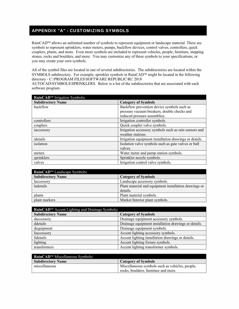
APPENDIX "A" - CUSTOMIZING SYMBOLS
RainCAD allows an unlimited number of symbols to represent equipment or landscape material. There are symbols to represent sprinklers, water meters, pumps, backflow devices, control valves, controllers, quick couplers, plants, and more. Even more symbols are included to represent vehicles, people, furniture, stepping stones, rocks and boulders, and more. You may customize any of these symbols to your specifications, or you may create your own symbols. All of the symbol files are located in one of several subdirectories. The subdirectories are located within the SYMBOLS subdirectory. For example, sprinkler symbols in RainCAD might be located in the following directory - C:\PROGRAM FILES\SOFTWARE REPUBLIC\RC 2018 AUTOCAD\SYMBOLS\SPRINKLERS. Below is a list of the subdirectories that are associated with each software program.
RainCAD Irrigation Symbols: Subdirectory Name Category of Symbols backflow Backflow prevention device symbols such as
pressure vacuum breakers, double checks and reduced pressure assemblies.
controllers Irrigation controller symbols.couplers Quick coupler valve symbols.iaccessory Irrigation accessory symbols such as rain sensors and
weather stations.idetails Irrigation equipment installation drawings or details.isolation Isolation valve symbols such as gate valves or ball
valves.meters Water meter and pump station symbols. sprinklers Sprinkler nozzle symbols.valves Irrigation control valve symbols.
RainCAD Landscape Symbols: Subdirectory Name Category of Symbols laccessory Landscape accessory symbols. ladetails Plant material and equipment installation drawings or
details.plants Plant material symbols.plant markers Marker/Interior plant symbols.
RainCAD Accent Lighting and Drainage Symbols: Subdirectory Name Category of Symbols daccessory Drainage equipment accessory symbols. ddetails Drainage equipment installation drawings or details.dequipment Drainage equipment symbols.liaccessory Accent lighting accessory symbols. lidetails Accent lighting installation drawings or details.lighting Accent lighting fixture symbols. transformers Accent lighting transformer symbols.
RainCAD Miscellaneous Symbols: Subdirectory Name Category of Symbols miscellaneous Miscellaneous symbols such as vehicles, people,
rocks, boulders, furniture and more.
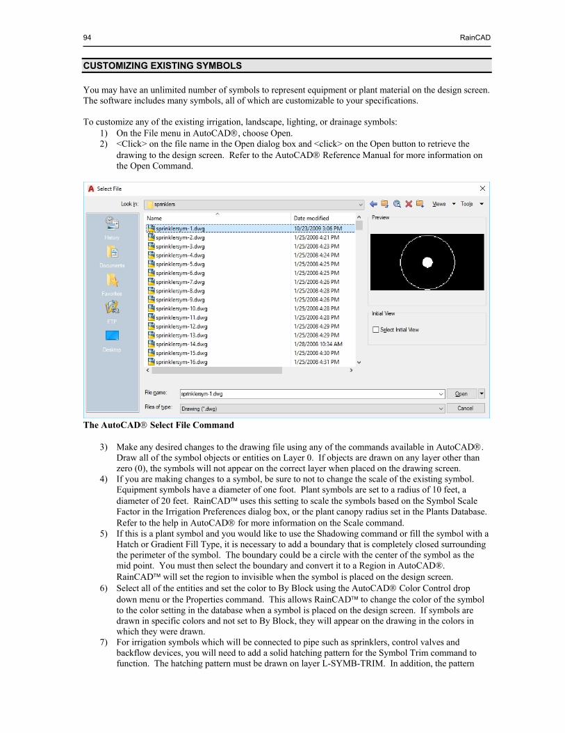
94 RainCAD
CUSTOMIZING EXISTING SYMBOLS
You may have an unlimited number of symbols to represent equipment or plant material on the design screen. The software includes many symbols, all of which are customizable to your specifications. To customize any of the existing irrigation, landscape, lighting, or drainage symbols:
1) On the File menu in AutoCAD, choose Open. 2) <Click> on the file name in the Open dialog box and <click> on the Open button to retrieve the
drawing to the design screen. Refer to the AutoCAD Reference Manual for more information on the Open Command.
The AutoCAD Select File Command
3) Make any desired changes to the drawing file using any of the commands available in AutoCAD.
Draw all of the symbol objects or entities on Layer 0. If objects are drawn on any layer other than zero (0), the symbols will not appear on the correct layer when placed on the drawing screen.
4) If you are making changes to a symbol, be sure to not to change the scale of the existing symbol. Equipment symbols have a diameter of one foot. Plant symbols are set to a radius of 10 feet, a diameter of 20 feet. RainCAD uses this setting to scale the symbols based on the Symbol Scale Factor in the Irrigation Preferences dialog box, or the plant canopy radius set in the Plants Database. Refer to the help in AutoCAD for more information on the Scale command.
5) If this is a plant symbol and you would like to use the Shadowing command or fill the symbol with a Hatch or Gradient Fill Type, it is necessary to add a boundary that is completely closed surrounding the perimeter of the symbol. The boundary could be a circle with the center of the symbol as the mid point. You must then select the boundary and convert it to a Region in AutoCAD®. RainCAD will set the region to invisible when the symbol is placed on the design screen.
6) Select all of the entities and set the color to By Block using the AutoCAD Color Control drop down menu or the Properties command. This allows RainCAD to change the color of the symbol to the color setting in the database when a symbol is placed on the design screen. If symbols are drawn in specific colors and not set to By Block, they will appear on the drawing in the colors in which they were drawn.
7) For irrigation symbols which will be connected to pipe such as sprinklers, control valves and backflow devices, you will need to add a solid hatching pattern for the Symbol Trim command to function. The hatching pattern must be drawn on layer L-SYMB-TRIM. In addition, the pattern
Appendix “A” – Symbols 95
must be set to By Layer for the color and the Draw Order in AutoCAD must be set to Send to Back.
8) Once you have completed the symbol and scaled the drawing, set the center of the symbol at the X and Y coordinates of 0,0. Set sprinkler symbols so that the desired insertion point of the symbol is located on the 0,0 coordinate. Select all of the symbol and enact the AutoCAD Move command. Set a point at the center of the symbol, or the desired insertion point. Type 0,0 in the Command Line as the second point of displacement and press <Enter>.
9) On the AutoCAD File menu, choose Save. Refer to the help in AutoCAD for more information on the Save As Command.
CREATING NEW SYMBOLS
You may have an unlimited number of symbols to represent equipment or plant material on the design screen. The software includes many symbols, however, you may create your own symbols as well. To create a new irrigation, landscape, lighting or drainage symbol:
1) On the AutoCAD File menu, choose New. 2) Use any of the tools available in AutoCAD to create a new symbol or detail drawing. Draw all of
the symbol objects or entities on Layer 0. If objects are drawn on any layer other than zero (0), the symbols will not appear on the correct layer when placed on the drawing screen.
3) Once you have created a new symbol, set the scale of the symbol equivalent to that of similar existing symbols. Equipment symbols have a diameter of one foot. Plant symbols are set to a radius of 10 feet, a diameter of 20 feet. RainCAD uses this setting to scale the symbols based on the Symbol Scale Factor in the Irrigation Preferences dialog box, or the plant canopy radius set in the Plants database. Refer to the help in AutoCAD for more information on the Scale command.
4) If this is a plant symbol and you would like to use the Shadowing command or fill the symbol with a Hatch or Gradient Fill Type, it is necessary to add a boundary that is completely closed surrounding the perimeter of the symbol. The boundary could be a circle with the center of the symbol as the mid point. You must then select the boundary and convert it to a Region in AutoCAD®. RainCAD will set the region to invisible when the symbol is placed on the design screen.
5) Select all of the entities and set the color to By Block using the AutoCAD Color Control drop down menu or the Properties command. This allows RainCAD to change the color of the symbol to the color setting in the database when a symbol is placed on the design screen. If symbols are drawn in specific colors and not set to By Block, they will appear on the drawing in the colors in which they were drawn.
6) For irrigation symbols which will be connected to pipe such as sprinklers, control valves and backflow devices, you will need to add a solid hatching pattern for the Symbol Trim command to function. The hatching pattern must be drawn on layer L-SYMB-TRIM. In addition, the pattern must be set to By Layer for the color and the Draw Order in AutoCAD must be set to Send to Back.
7) Once you have completed the symbol and scaled the drawing, set the center of the symbol at the X and Y coordinates of 0,0. Set sprinkler symbols so that the desired insertion point of the symbol is located on the 0,0 coordinate. Select all of the symbol and enact the AutoCAD Move command. Set a point at the center of the symbol, or the desired insertion point. Type 0,0 in the Command Line as the second point of displacement and press <Enter>.
8) On the AutoCAD File menu, choose Save. Enter the output drawing file name and be sure to save the symbol drawing in the proper directory. All of the symbols are saved in numerical order beginning with the number one (1) along with a prefix. You should name the drawing as the next number in numerical order. Keep the same naming convention as other symbols in the category. For example, plant symbols begin with the prefix plantsym- or plantsym-ext, while sprinkler symbols begin with the prefix sprinklersym-. Refer to the help in AutoCAD for more information on the Save command.

96 RainCAD
This page is intentionally left blank.
INDEX
A
Accessories - Irrigation ꞏ 53 Add Run Set ꞏ 50 Add Selection to Zone ꞏ 29 Adding a Plant to the Database ꞏ 86 Adding a Sprinkler to the Database ꞏ 81 Along a Polyline – Miscellaneous Symbols ꞏ 71 Along a Polyline - Plants ꞏ 60 Along a Polyline - Sprinklers ꞏ 26 Application Rate ꞏ 75 Apply Discount Rate ꞏ 77 Apply To All Plant Sizes ꞏ 87 Arc Patterns ꞏ 32 Area Volume Calcs ꞏ 70 Assumptions ꞏ 3 Auto Snap Pipe to Symbols ꞏ 38, 39 Auto Symbol Layout ꞏ 71 Automatic Lateral Line Pipe Sizing ꞏ 46 Automatic Mainline Pipe Sizing ꞏ 49, 74 Automatic Pipe Sizing ꞏ 47, 49, 50 Automatic Piping ꞏ 34, 35, 36 Automatic Radius Reduction ꞏ 25 Automatically Calculate Full Circle Row Angle ꞏ
25 Automatically Color Code Pipe ꞏ 45, 46
B
Backflow Devices ꞏ 42 Bill of Materials ꞏ 76 Blocks, Purging ꞏ 17 Blue Scale ꞏ 75 Botanical and Common Names ꞏ 79 Botanical Name ꞏ 86 Boundary Control ꞏ 64 Boundary Line ꞏ 23, 63, 64, 78
C
Calcs Menu ꞏ 28, 33, 47, 49 Calculate as a Percent of Pipe ꞏ 78 Calculate Distribution ꞏ 75 Calculate from Drawing ꞏ 78 Calculate from Entire Drawing ꞏ 78 Check Sizes Used in Sizing ꞏ 46 Check Zones for Auto Pipe Sizing ꞏ 47 Check Zones for Automatic Lateral Line Piping ꞏ
34 Christiansen's Uniformity Coefficient (CU) ꞏ 74
Column Factor, Legend ꞏ 79 Combining Plant Symbols ꞏ 64 Common and Botanical Names ꞏ 79 Common Name ꞏ 86 Company Information ꞏ 76, 77 Conclusion ꞏ 91 Connect Plant Symbols ꞏ 64 Control Valve Notations ꞏ 54 Control Valves ꞏ 32 Controller Assignment ꞏ 54 Controller Identifier ꞏ 54 Controllers ꞏ 53 Coverage Patterns ꞏ 32 Create Legend ꞏ 79 Creating New Symbols ꞏ 95 Custom Line Styles ꞏ 19 Customizing Existing Symbols ꞏ 94 Customizing Symbols ꞏ 93
D
Database Menu ꞏ 19 Default Pressure, Sprinkler ꞏ 82 Delete Run Set ꞏ 50 Deleting or Replacing Plants ꞏ 64 Densogram - Distribution ꞏ 75 Desired Sprinkler Layout ꞏ 25 Desired Sprinkler Spacing ꞏ 25 Dialog Boxes ꞏ 13, 15 Digitizer ꞏ 3, 4 Discount Rate ꞏ 78 Distribution ꞏ 74, 82 Distribution Data ꞏ 76, 82 Distribution Uniformity (DU) ꞏ 74 Drawing Units ꞏ 17 Drawing Utilities ꞏ 18
E
Elevation, Hydraulics ꞏ 74 Equipment Data, Sprinkler ꞏ 82 Estimate ꞏ 76 Even Spacing - Plants ꞏ 61 Even Spacing - Symbols ꞏ 71 Exact Spacing - Plants ꞏ 61 Exact Spacing - Symbols ꞏ 71
F
Fill Angle ꞏ 88 Fill Color ꞏ 59, 88
98 RainCAD
Fill Material ꞏ 70 Fill Material Database ꞏ 69 Fill Materials ꞏ 69 Fill Materials, List by Area ꞏ 78 Fill Scale ꞏ 88 Fill Type ꞏ 59, 88 Fittings Calculation ꞏ 78 Flow ꞏ 82
G
General Plant Data ꞏ 86 Get Flow From Selection ꞏ 29, 30 Get Set Flow ꞏ 50 Getting Started ꞏ 3 Gradient Angle ꞏ 59 Gradient Fill ꞏ 59 Gradient Fill Type ꞏ 88 Gradient Type ꞏ 59, 88 Grove ꞏ 64
H
Hatch Angle ꞏ 59 Hatch Color ꞏ 59, 66 Hatch Fill Type ꞏ 88 Hatch Pattern ꞏ 59, 66 Hatch Pattern Palette ꞏ 88 Hatch Scale ꞏ 59 Help ꞏ 4, 7 Hydraulic Calculations ꞏ 73, 74 Hydraulics Viewer ꞏ 74
I
Insertion Point ꞏ 37 Installation ꞏ 4 Installation Details - Irrigation ꞏ 55 Installation Details - Landscape ꞏ 72 Internet – Software Republic ꞏ 4 Introduction ꞏ 1 Irrigation Installation Details ꞏ 55 Irrigation Preferences ꞏ 45, 48, 94, 95
L
Label Locations ꞏ 46, 47 Landscape Installation Details ꞏ 72 Landscape Preferences ꞏ 79, 86 Lateral Line ꞏ 38 Lateral Line Pipe ꞏ 47 Lateral Line Piping Errors ꞏ 48 Lateral Line Row Variance ꞏ 35 Layer Name ꞏ 19 Layers ꞏ 31, 32, 34
Layout Mode - Plants ꞏ 58, 59, 60, 63 Leader Type, Symbol Label ꞏ 68, 69 Legend ꞏ 19 Legend Text Style ꞏ 79 Legends ꞏ 79 Line Styles ꞏ 19 Line Styles Database ꞏ 19 List Fill Materials by Area ꞏ 78 List Price ꞏ 78 Location of Pipe Size Labels ꞏ 46 Looped Network ꞏ 50, 74
M
Mainline ꞏ 43 Mainline Line Type Scale ꞏ 45 Mainline Pipe ꞏ 49, 50 Mainline Pipe Details Viewer ꞏ 50 Mainline Piping ꞏ 42, 43 Manual Length of Lateral Line Branches ꞏ 35 Manual Pipe Sizing ꞏ 51 Manual Piping ꞏ 37, 38, 43, 45 Manual Plant Layout Mode ꞏ 58 Manual Sprinkler Placement ꞏ 26 Manual Symbol Label ꞏ 68 Marker/Interiors ꞏ 87 Material/Estimate ꞏ 19, 70, 76 Material/Estimate Labels ꞏ 76 Material\Estimate ꞏ 23, 77, 78 Material\Estimate Preview ꞏ 78 Menu Bar ꞏ 13 Menu System ꞏ 14 Miscellaneous Symbols ꞏ 70, 71 Monitor ꞏ 7 Mouse ꞏ 3, 4 Multiple Valve Operation ꞏ 49, 50, 74
N
Name Display Type ꞏ 79 Notation Type - Valve ꞏ 55
O
Open Command, AutoCAD ꞏ 94 Options ꞏ 76 Options/Info ꞏ 17 Options/Info Menu ꞏ 45, 52, 64 Outline Combine Mode ꞏ 61, 64 Overhead ꞏ 77
P
Palette Assignments, Plants ꞏ 89 Palette Assignments, Sprinklers ꞏ 84
Index 99
Palette Name ꞏ 24 Percent of Diameter ꞏ 25 Percent of Overspray Allowed ꞏ 25 Percent of Pipe ꞏ 78 Performance Data ꞏ 82 Pipe Category ꞏ 38 Pipe Database ꞏ 46 Pipe Hop ꞏ 40, 41, 43 Pipe Hop Radius ꞏ 41 Pipe Placement ꞏ 34, 36, 38, 43 Pipe Size ꞏ 38 Pipe Size Label Color Setting ꞏ 45 Pipe Size Label Leader Type ꞏ 45 Pipe Size Label Locations ꞏ 46 Pipe Size Label Offset ꞏ 45, 48 Pipe Size Label Text Size ꞏ 45 Pipe Size Label Type ꞏ 48 Pipe Size Labels ꞏ 39, 43 Pipe Sizing Options ꞏ 45 Pipe Snap Distance ꞏ 38 Pipe Symbol Color ꞏ 46 Pipe Type ꞏ 38, 43 Piping Errors ꞏ 48 Plant Abbreviation ꞏ 79 Plant Data ꞏ 58 Plant Database ꞏ 58 Plant Layout ꞏ 63 Plant Material ꞏ 57, 58 Plant Notations ꞏ 67 Plant Offset ꞏ 64 Plant Palette Assignments ꞏ 89 Plant Placement ꞏ 57, 59, 60, 62, 89 Plant Placement – Along a Polyline ꞏ 60 Plant Placement – Within a Boundary ꞏ 62 Plant Radius ꞏ 60, 63, 87 Plant Rotation ꞏ 61, 64 Plant Search ꞏ 57, 89 Plant Shadows ꞏ 66 Plant Size ꞏ 58, 59, 60, 63 Plant Size Data ꞏ 86 Plant Sizes ꞏ 87 Plant Symbol Size, Legend ꞏ 79 Plants – Combining Symbols ꞏ 64 Plants Database ꞏ 85 Polyline Offset - Plants ꞏ 60 Precipitation Rate ꞏ 75 Pressure ꞏ 82 Pressure Variance ꞏ 46 Profit ꞏ 77 Project Infomration ꞏ 77 Project Information ꞏ 77 Properties ꞏ 51, 52, 64 Properties, AutoCAD® ꞏ 74 Proposal ꞏ 76 Pump ꞏ 22 Purge ꞏ 18 Purging Blocks ꞏ 17
Q
Quantity Label ꞏ 61, 68 Quantity of Plants ꞏ 64
R
Radius of Throw ꞏ 82 RAM ꞏ 3 Random Plant Layout ꞏ 64 Random Rotation ꞏ 71 Remove Selection from Zone ꞏ 29, 33 Report Configuration ꞏ 77 Report Field Configuration ꞏ 78 Report Style ꞏ 76 Report Type ꞏ 78 Resolution ꞏ 3, 7 Run Sets ꞏ 50, 74
S
Save Command, AutoCAD ꞏ 95 Scale Command, AutoCAD ꞏ 94, 95 Scheduling Coefficient (SC) ꞏ 74 Selection Conventions ꞏ 3 Shadow Angle ꞏ 66 Shadow Offset ꞏ 66 Shortcut Key ꞏ 3, 14, 41 Show All Symbols ꞏ 87 Show Grid, Legend ꞏ 79 Site Information ꞏ 77 Sketch Factor ꞏ 87 Sleeving ꞏ 55 Spacing - Plants ꞏ 60, 64 Spacing Type ꞏ 61, 71 Species Data ꞏ 89 Sprinkler Distribution ꞏ 74 Sprinkler Layout ꞏ 25 Sprinkler Offset ꞏ 25, 26 Sprinkler Palette Assignments ꞏ 24, 84 Sprinkler Placement ꞏ 24, 25, 26 Sprinkler Placement – Along a Polyline ꞏ 25 Sprinkler Placement – Within a Boundary ꞏ 24 Sprinkler Spacing ꞏ 25 Sprinklers Database ꞏ 9, 81 Squiggly Leader ꞏ 45 Stagger % ꞏ 60, 64 Stagger Distance ꞏ 60, 64 Starting the Software ꞏ 4 Station Assignment ꞏ 54 Steps to a Proper Irrigation Design ꞏ 11 Suggested Steps ꞏ 11 Supplies ꞏ 9, 84 Supplies Database ꞏ 85 Support ꞏ 4 Symbol Browser, Plants ꞏ 87 Symbol Color ꞏ 87
100 RainCAD
Symbol Label ꞏ 68 Symbol Offset ꞏ 71 Symbol Scale Factor ꞏ 94, 95 Symbol Type ꞏ 59, 87 Symbols - Combining Plants ꞏ 64 Symbols - Miscellaneous ꞏ 70 System Requirements ꞏ 3
T
Tax Direct Labor ꞏ 77 Technical Support ꞏ 4 Text Size, Symbol Label ꞏ 68, 69 Things You Should Do ꞏ 9 Things You Should Know ꞏ 7 Tied Assemblies ꞏ 9, 84 Tied Assemblies Database ꞏ 85 Toolbar ꞏ 4, 13 Toolbars ꞏ 14 Total Flow ꞏ 28 Trim Plant Symbols ꞏ 64 Typographical Conventions ꞏ 3
U
Underlined Letters ꞏ 13, 14 Undo ꞏ 41 Units of Measurement ꞏ 17
V
Valve Notations ꞏ 54 Valve Zone Assignment ꞏ 33 Valve-in-Head Zone Assignment ꞏ 33 Velocity ꞏ 46 View Material Estimate ꞏ 78
W
Water Meter ꞏ 22 Water Source/Zone Assignment ꞏ 29, 30, 33 Water Sources ꞏ 22 Watering Time Factor (WTF%) ꞏ 75 Web Site – Software Republic ꞏ 4 Within a Boundary Line ꞏ 84 Within a Boundary Line - Plants ꞏ 63 Within a Boundary Line - Sprinklers ꞏ 24
Z
Zone Assignment – Remove Sprinkler ꞏ 29 Zone Assignment – Remove Valve ꞏ 33 Zone Assignments ꞏ 27, 28, 34 Zone Number Assignment ꞏ 29, 30, 33 Zone Reassignment ꞏ 30 Zoom Commands ꞏ 31