Embed Size (px)
Citation preview

AutoCAD Civil 3D 2009
ESSENTIALS
SDC
Schroff Development Corporation www.schroff.com
Better Textbooks. Lower Prices.
PUBLICATIONS

Copyrighted Material
Copyrighted
Material
Copyrighted Material
Copyrighted
Material
Alignments and Profiles
© 2008. Do not duplicate. 4 - 29
Section 2: Profiles
In this section you learn how to:
Create and manage Profile Views
Create a Profile from a surface and by layout
Work with Profile Transparent Commands
Display existing and proposed Elevations correctly in Profile Bands

Copyrighted Material
Copyrighted
Material
Copyrighted Material
Copyrighted
Material
AutoCAD Civil 3D 2009 Essentials
4 - 30 © 2008. Do not duplicate.
Profiles Overview
A profile is the second plane of a roadway design. It is a view of the alignment from one side of the centerline showing elevations along the alignment. An AutoCAD Civil 3D profile is a combination of a profile view and any number of profiles displayed in the view.
A profile view consists of a profile grid and its annotation. The view’s vertical lines represent alignment stationing and the horizontal lines represent elevations.
A profile represents a surface or roadway vertical design. A typical road design profile view contains two profiles: the existing ground and a proposed vertical design. The existing ground profile represents elevations along the path of the alignment, usually from a sampled surface. The proposed vertical defines elevations along the path of the proposed roadway. You can have any number of existing and proposed vertical alignments displayed in the same profile view at the same time.
AutoCAD Civil 3D Profiles are managed by:
Profile View Properties: Settings specific to individual profiles, such as datum elevation and maximum height.
Profile View Styles: Affect how the grid and its annotation are displayed.
Profile Styles: Control how the profile linework is displayed.
Copyrighted Material
Copyrighted
Material
Copyrighted Material
Copyrighted
Material
Alignments and Profiles
© 2008. Do not duplicate. 4 - 31
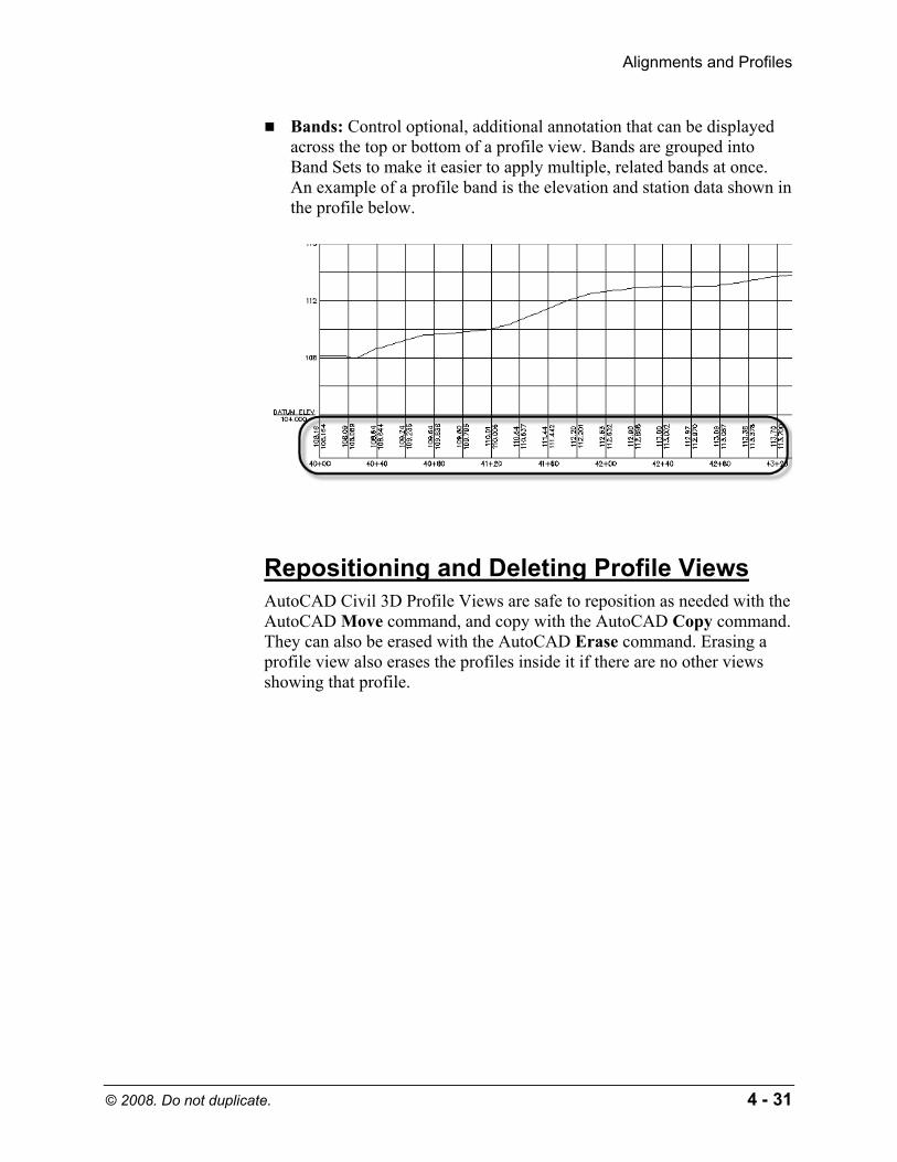
Bands: Control optional, additional annotation that can be displayed across the top or bottom of a profile view. Bands are grouped into Band Sets to make it easier to apply multiple, related bands at once. An example of a profile band is the elevation and station data shown in the profile below.
Repositioning and Deleting Profile Views AutoCAD Civil 3D Profile Views are safe to reposition as needed with the AutoCAD Move command, and copy with the AutoCAD Copy command. They can also be erased with the AutoCAD Erase command. Erasing a profile view also erases the profiles inside it if there are no other views showing that profile.
Copyrighted Material
Copyrighted
Material
Copyrighted Material
Copyrighted
Material
AutoCAD Civil 3D 2009 Essentials
4 - 32 © 2008. Do not duplicate.
Create Profiles from Surface
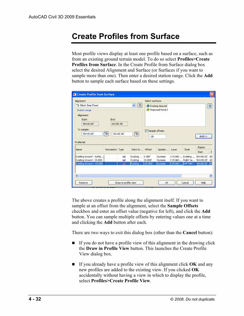
Most profile views display at least one profile based on a surface, such as from an existing ground terrain model. To do so select Profiles>Create Profiles from Surface. In the Create Profile from Surface dialog box select the desired Alignment and Surface (or Surfaces if you want to sample more than one). Then enter a desired station range. Click the Add button to sample each surface based on these settings.
The above creates a profile along the alignment itself. If you want to sample at an offset from the alignment, select the Sample Offsets checkbox and enter an offset value (negative for left), and click the Add button. You can sample multiple offsets by entering values one at a time and clicking the Add button after each.
There are two ways to exit this dialog box (other than the Cancel button):
If you do not have a profile view of this alignment in the drawing click the Draw in Profile View button. This launches the Create Profile View dialog box.
If you already have a profile view of this alignment click OK and any new profiles are added to the existing view. If you clicked OK accidentally without having a view in which to display the profile, select Profiles>Create Profile View.
Copyrighted Material
Copyrighted
Material
Copyrighted Material
Copyrighted
Material
Alignments and Profiles
© 2008. Do not duplicate. 4 - 33
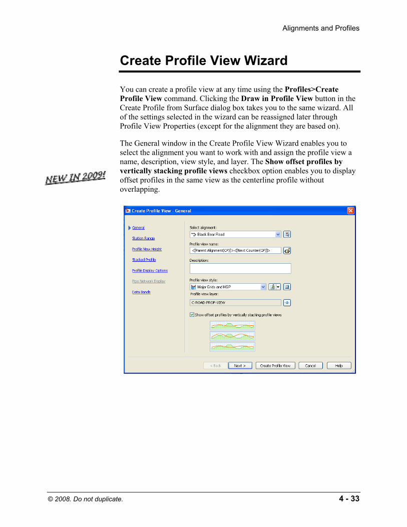
Create Profile View Wizard
You can create a profile view at any time using the Profiles>Create Profile View command. Clicking the Draw in Profile View button in the Create Profile from Surface dialog box takes you to the same wizard. All of the settings selected in the wizard can be reassigned later through Profile View Properties (except for the alignment they are based on).
The General window in the Create Profile View Wizard enables you to select the alignment you want to work with and assign the profile view a name, description, view style, and layer. The Show offset profiles by vertically stacking profile views checkbox option enables you to display offset profiles in the same view as the centerline profile without overlapping.

Copyrighted Material
Copyrighted
Material
Copyrighted Material
Copyrighted
Material
AutoCAD Civil 3D 2009 Essentials
4 - 34 © 2008. Do not duplicate.
The Station Range second window enables you to select the station range you want to work with. Automatic includes the entire alignment’s length.
The Profile View Height window enables you to select the desired height of the profile grid.
The Automatic option creates a profile view that is sized to avoid having to be split.
Copyrighted Material
Copyrighted
Material
Copyrighted Material
Copyrighted
Material
Alignments and Profiles
© 2008. Do not duplicate. 4 - 35
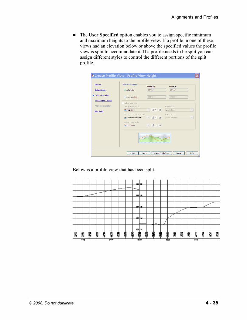
The User Specified option enables you to assign specific minimum and maximum heights to the profile view. If a profile in one of these views had an elevation below or above the specified values the profile view is split to accommodate it. If a profile needs to be split you can assign different styles to control the different portions of the split profile.
Below is a profile view that has been split.
Copyrighted Material
Copyrighted
Material
Copyrighted Material
Copyrighted
Material
AutoCAD Civil 3D 2009 Essentials
4 - 36 © 2008. Do not duplicate.
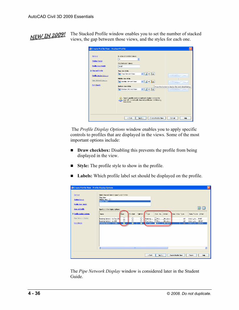
The Stacked Profile window enables you to set the number of stacked views, the gap between those views, and the styles for each one.
The Profile Display Options window enables you to apply specific controls to profiles that are displayed in the views. Some of the most important options include:
Draw checkbox: Disabling this prevents the profile from being displayed in the view.
Style: The profile style to show in the profile.
Labels: Which profile label set should be displayed on the profile.
The Pipe Network Display window is considered later in the Student Guide.
Copyrighted Material
Copyrighted
Material
Copyrighted Material
Copyrighted
Material
Alignments and Profiles
© 2008. Do not duplicate. 4 - 37
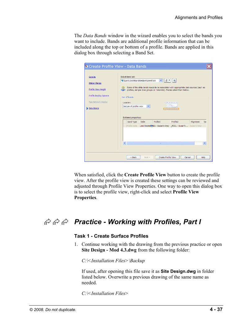
The Data Bands window in the wizard enables you to select the bands you want to include. Bands are additional profile information that can be included along the top or bottom of a profile. Bands are applied in this dialog box through selecting a Band Set.
When satisfied, click the Create Profile View button to create the profile view. After the profile view is created these settings can be reviewed and adjusted through Profile View Properties. One way to open this dialog box is to select the profile view, right-click and select Profile View Properties.
Practice - Working with Profiles, Part I
Task 1 - Create Surface Profiles 1. Continue working with the drawing from the previous practice or open
Site Design - Mod 4.3.dwg from the following folder:
C:\<Installation Files>\Backup
If used, after opening this file save it as Site Design.dwg in folder listed below. Overwrite a previous drawing of the same name as needed.
C:\<Installation Files>

Copyrighted Material
Copyrighted
Material
Copyrighted Material
Copyrighted
Material
AutoCAD Civil 3D 2009 Essentials
4 - 38 © 2008. Do not duplicate.
2. Zoom Extents and Pan the drawing so that you have some open drawing area in which to create profiles.
3. Select Profiles>Create Profile from Surface. In the dialog box select the Susan’s Way alignment, highlight the Existing Ground surface and press the Add button. This samples an existing ground profile along the centerline, the entire length of Susan’s Way. Select the Sample offsets checkbox and type 14 in the Sample offsets box. Click the Add>> button, and set the style below to Right Sample Profile for the right TBC. In the Sample offsets box, type -14, click the Add>> button, and set the style below to Left Sample Profile for the left TBC.
4. Click the Draw in Profile View button. (If you clicked OK instead, select Profiles>Create Profile View).
Copyrighted Material
Copyrighted
Material
Copyrighted Material
Copyrighted
Material
Alignments and Profiles
© 2008. Do not duplicate. 4 - 39
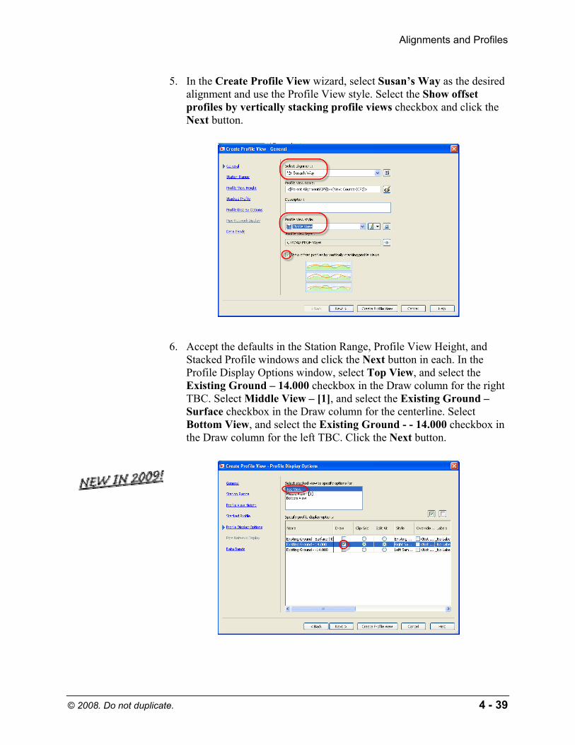
5. In the Create Profile View wizard, select Susan’s Way as the desired alignment and use the Profile View style. Select the Show offset profiles by vertically stacking profile views checkbox and click the Next button.
6. Accept the defaults in the Station Range, Profile View Height, and Stacked Profile windows and click the Next button in each. In the Profile Display Options window, select Top View, and select the Existing Ground – 14.000 checkbox in the Draw column for the right TBC. Select Middle View – [1], and select the Existing Ground – Surface checkbox in the Draw column for the centerline. Select Bottom View, and select the Existing Ground - - 14.000 checkbox in the Draw column for the left TBC. Click the Next button.

Copyrighted Material
Copyrighted
Material
Copyrighted Material
Copyrighted
Material
AutoCAD Civil 3D 2009 Essentials
4 - 40 © 2008. Do not duplicate.
7. In the Data Bands window accept the default EG-FG Elevations and Stations and click the Create Profile View button.
Copyrighted Material
Copyrighted
Material
Copyrighted Material
Copyrighted
Material
Alignments and Profiles
© 2008. Do not duplicate. 4 - 41
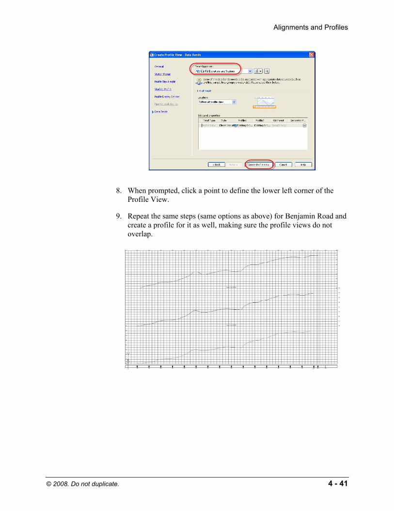
8. When prompted, click a point to define the lower left corner of the Profile View.
9. Repeat the same steps (same options as above) for Benjamin Road and create a profile for it as well, making sure the profile views do not overlap.
Copyrighted Material
Copyrighted
Material
Copyrighted Material
Copyrighted
Material
AutoCAD Civil 3D 2009 Essentials
4 - 42 © 2008. Do not duplicate.
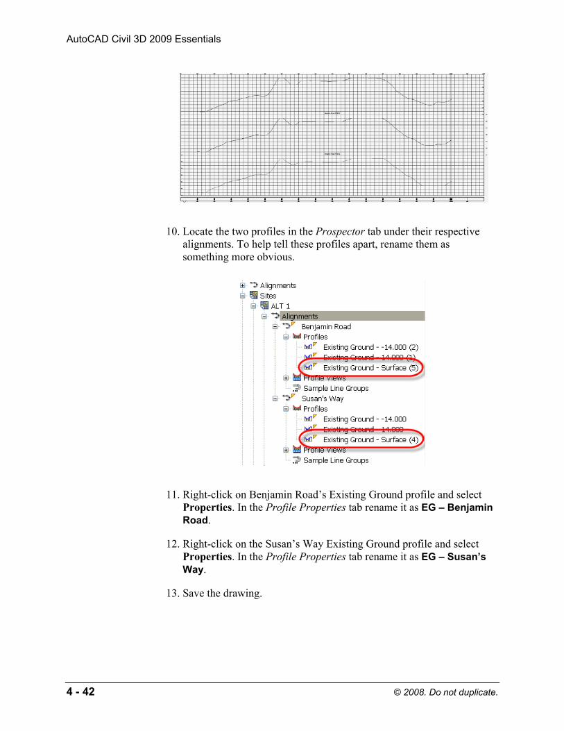
10. Locate the two profiles in the Prospector tab under their respective alignments. To help tell these profiles apart, rename them as something more obvious.
11. Right-click on Benjamin Road’s Existing Ground profile and select Properties. In the Profile Properties tab rename it as EG – Benjamin Road.
12. Right-click on the Susan’s Way Existing Ground profile and select Properties. In the Profile Properties tab rename it as EG – Susan’s Way.
13. Save the drawing.
Copyrighted Material
Copyrighted
Material
Copyrighted Material
Copyrighted
Material
Alignments and Profiles
© 2008. Do not duplicate. 4 - 43
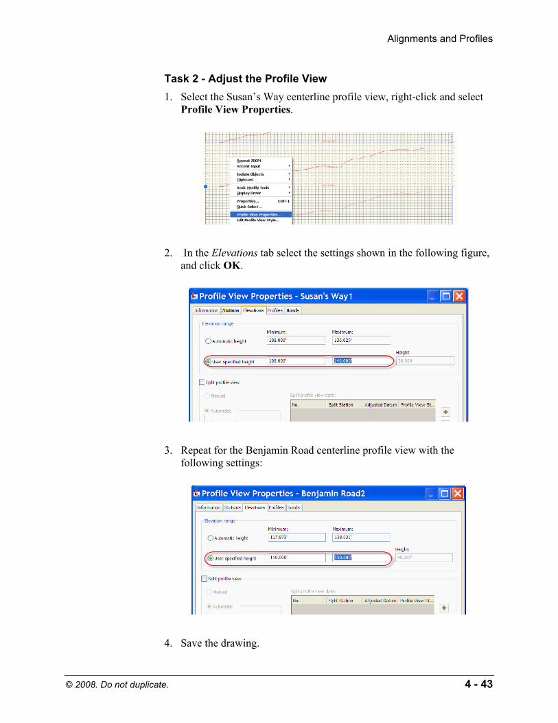
Task 2 - Adjust the Profile View 1. Select the Susan’s Way centerline profile view, right-click and select
Profile View Properties.
2. In the Elevations tab select the settings shown in the following figure, and click OK.
3. Repeat for the Benjamin Road centerline profile view with the following settings:
4. Save the drawing.

Copyrighted Material
Copyrighted
Material
Copyrighted Material
Copyrighted
Material
AutoCAD Civil 3D 2009 Essentials
4 - 44 © 2008. Do not duplicate.
Finished Ground Profiles
Finished ground profiles (also referred to as proposed profiles or proposed vertical alignments) often are created interactively through the Profile Layout toolbar, similar to how alignments are created by layout. The toolbar can be opened using Profiles>Create by Layout and Profiles>Edit Profile Geometry.
Vertical curves transition a vehicle from one tangent grade to another and occur in two situations: Crest (top of a hill) and Sag (valley).
There are four types of vertical curves to transition between changing the tangent grades of a crest or sag: Circular, Parabolic, Asymmetric Parabolic, and Best Fit. Roadways almost always use parabolic (equal length) curves. Asymmetric parabolic curves are usually only used if layout constraints do not permit an equal-length curve. True circular curves are used in some parts of the world for low-speed rail design and generally should never be used for roadways (which otherwise could lead to vehicle vaulting or bottoming out). Best fit curves follow the most likely path through a series of points.
In the Settings tab, in the Profile heading, the Edit Features Settings sets the default curve type, styles, and command settings.
Most vertical designs have regulations affecting the minimum and maximum values for tangent slopes, distances along tangents between vertical curves, and safety design parameters for passing sight and stopping sight distances. Refer to local design manuals for more information on these design constraints.
The points connecting tangents in a finished ground profile are referred to as a Point of Vertical Intersection (PVI).

Copyrighted Material
Copyrighted
Material
Copyrighted Material
Copyrighted
Material
Alignments and Profiles
© 2008. Do not duplicate. 4 - 45
Creating and Editing Profiles
Similar to the Alignments Layout toolbar, the Profile Layout toolbar contains an overall vista (Profile Grid View) and Profile Layout Parameters (segment data viewer). These vistas enable you to review and edit the vertical design. The settings used when creating a finished ground profile can be selected through the Draw Tangents flyout menu in the toolbar. This toolbar is used to edit any kind of profile, including profiles created from surfaces.
Other toolbar commands Add, Delete, or Move individual tangent, PVIs, or vertical curve segments.
When editing a profile in the layout parameters or grid view, editable parameters appear in black.
You can graphically edit a design profile using grips.
When graphically editing a vertical alignment, the tangents, PVIs, and vertical curves display grips that represent specific editing functions.
The red triangular grip moves the PVI to a new station and/or elevation.
The cyan triangles extend the selected tangent, hold its grade, and modify the grade of the opposite tangent to relocate the PVI.
The middle or end circular grips lengthen or shorten the vertical curve without affecting the location of the PVI.
Copyrighted Material
Copyrighted
Material
Copyrighted Material
Copyrighted
Material
AutoCAD Civil 3D 2009 Essentials
4 - 46 © 2008. Do not duplicate.
When you move the cursor to the original location of the grip, the cursor snaps to that location.
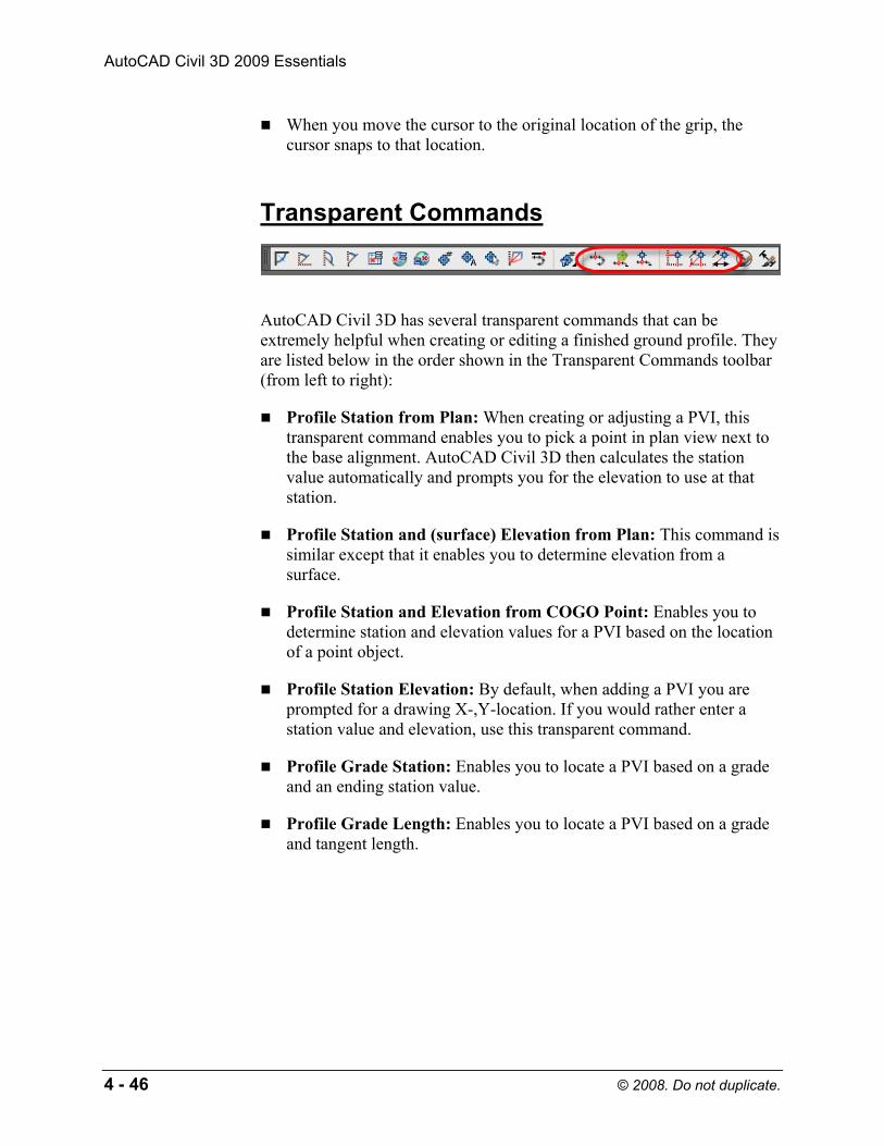
Transparent Commands
AutoCAD Civil 3D has several transparent commands that can be extremely helpful when creating or editing a finished ground profile. They are listed below in the order shown in the Transparent Commands toolbar (from left to right):
Profile Station from Plan: When creating or adjusting a PVI, this transparent command enables you to pick a point in plan view next to the base alignment. AutoCAD Civil 3D then calculates the station value automatically and prompts you for the elevation to use at that station.
Profile Station and (surface) Elevation from Plan: This command is similar except that it enables you to determine elevation from a surface.
Profile Station and Elevation from COGO Point: Enables you to determine station and elevation values for a PVI based on the location of a point object.
Profile Station Elevation: By default, when adding a PVI you are prompted for a drawing X-,Y-location. If you would rather enter a station value and elevation, use this transparent command.
Profile Grade Station: Enables you to locate a PVI based on a grade and an ending station value.
Profile Grade Length: Enables you to locate a PVI based on a grade and tangent length.
Copyrighted Material
Copyrighted
Material
Copyrighted Material
Copyrighted
Material
Alignments and Profiles
© 2008. Do not duplicate. 4 - 47
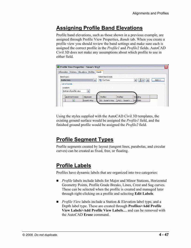
Assigning Profile Band Elevations Profile band elevations, such as those shown in a previous example, are assigned through Profile View Properties, Bands tab. When you create a profile view you should review the band settings and make sure each is assigned the correct profile in the Profile1 and Profile2 fields. AutoCAD Civil 3D does not make any assumptions about which profile to use in either field.
Using the styles supplied with the AutoCAD Civil 3D templates, the existing ground surface would be assigned the Profile1 field, and the finished ground profile would be assigned the Profile2 field.
Profile Segment Types Profile segments created by layout (tangent lines, parabolas, and circular curves) can be created as fixed, free, or floating.
Profile Labels Profiles have dynamic labels that are organized into two categories:
Profile labels include labels for Major and Minor Stations, Horizontal Geometry Points, Profile Grade Breaks, Lines, Crest and Sag curves. These can be selected when the profile is created and managed later through right-clicking on a profile and selecting Edit Labels.
Profile View labels include a Station & Elevation label type, and a Depth label type. These are created through Profiles>Add Profile View Labels>Add Profile View Labels… and can be removed with the AutoCAD Erase command.
Copyrighted Material
Copyrighted
Material
Copyrighted Material
Copyrighted
Material
AutoCAD Civil 3D 2009 Essentials
4 - 48 © 2008. Do not duplicate.
Practice - Working with Profiles, Part II
Task 1 - Create FG Profile 1. Continue working with the drawing from the previous practice or open
Site Design - Mod 3.4.dwg from the following folder:
C:\<Installation Files>\Backup
If used, after opening this file save it as Site Design.dwg in the folder listed below. Overwrite a previous drawing of the same name as needed.
C:\<Installation Files>
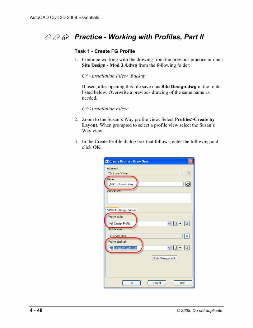
2. Zoom to the Susan’s Way profile view. Select Profiles>Create by Layout. When prompted to select a profile view select the Susan’s Way view.
3. In the Create Profile dialog box that follows, enter the following and click OK.
Copyrighted Material
Copyrighted
Material
Copyrighted Material
Copyrighted
Material
Alignments and Profiles
© 2008. Do not duplicate. 4 - 49
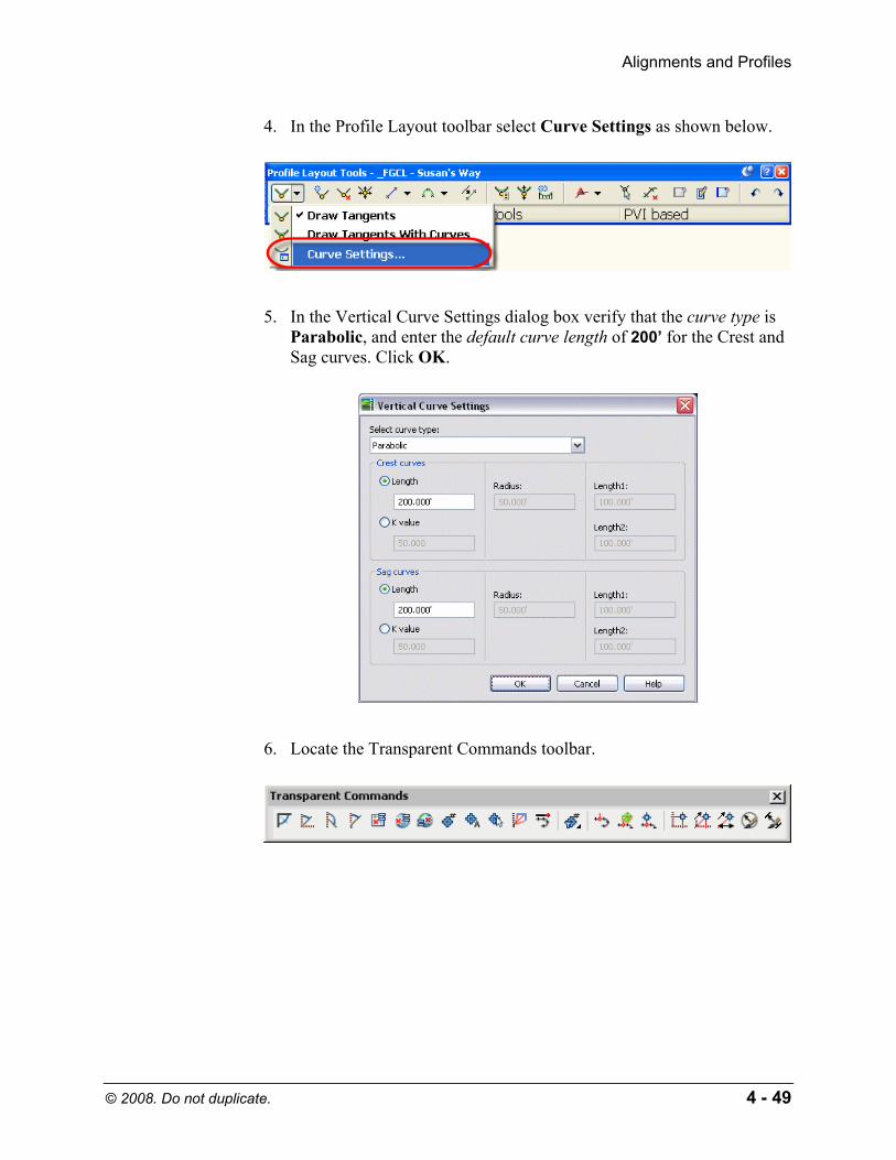
4. In the Profile Layout toolbar select Curve Settings as shown below.
5. In the Vertical Curve Settings dialog box verify that the curve type is Parabolic, and enter the default curve length of 200’ for the Crest and Sag curves. Click OK.
6. Locate the Transparent Commands toolbar.
Copyrighted Material
Copyrighted
Material
Copyrighted Material
Copyrighted
Material
AutoCAD Civil 3D 2009 Essentials
4 - 50 © 2008. Do not duplicate.
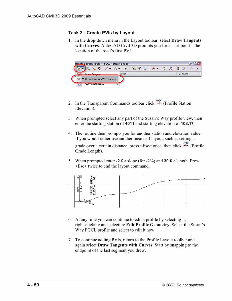
Task 2 - Create PVIs by Layout 1. In the drop-down menu in the Layout toolbar, select Draw Tangents
with Curves. AutoCAD Civil 3D prompts you for a start point – the location of the road’s first PVI.
2. In the Transparent Commands toolbar click (Profile Station Elevation).
3. When prompted select any part of the Susan’s Way profile view, then enter the starting station of 4011 and starting elevation of 108.17.
4. The routine then prompts you for another station and elevation value. If you would rather use another means of layout, such as setting a grade over a certain distance, press <Esc> once, then click (Profile Grade Length).
5. When prompted enter -2 for slope (for -2%) and 30 for length. Press <Esc> twice to end the layout command.
6. At any time you can continue to edit a profile by selecting it, right-clicking and selecting Edit Profile Geometry. Select the Susan’s Way FGCL profile and select to edit it now.
7. To continue adding PVIs, return to the Profile Layout toolbar and again select Draw Tangents with Curves. Start by snapping to the endpoint of the last segment you drew.
Copyrighted Material
Copyrighted
Material
Copyrighted Material
Copyrighted
Material
Alignments and Profiles
© 2008. Do not duplicate. 4 - 51
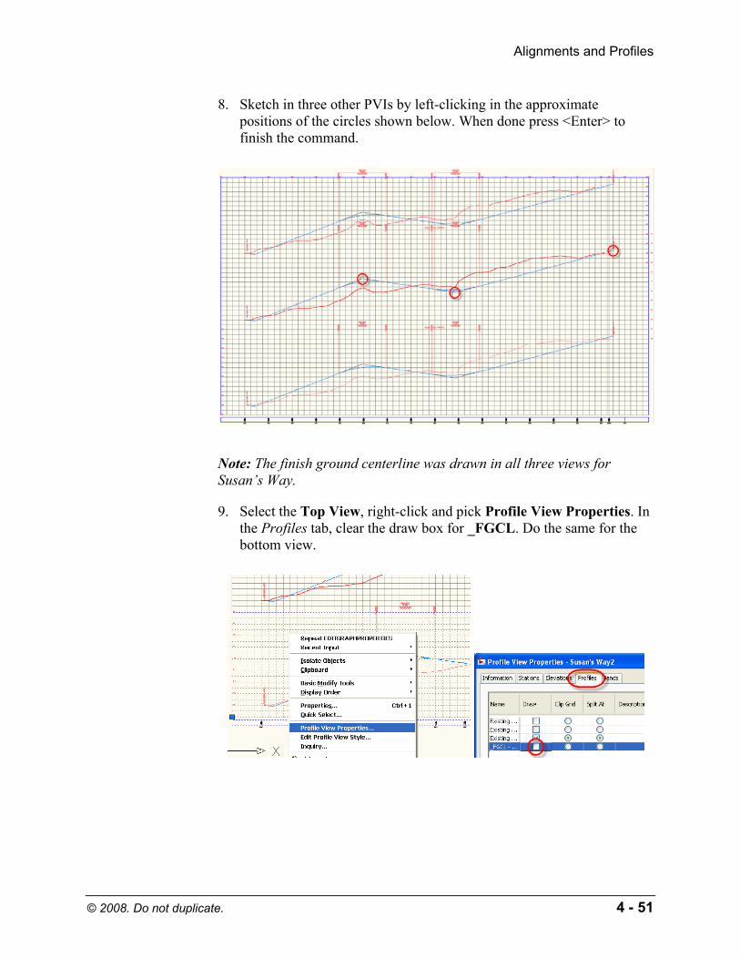
8. Sketch in three other PVIs by left-clicking in the approximate positions of the circles shown below. When done press <Enter> to finish the command.
Note: The finish ground centerline was drawn in all three views for Susan’s Way.
9. Select the Top View, right-click and pick Profile View Properties. In the Profiles tab, clear the draw box for _FGCL. Do the same for the bottom view.
Copyrighted Material
Copyrighted
Material
Copyrighted Material
Copyrighted
Material
AutoCAD Civil 3D 2009 Essentials
4 - 52 © 2008. Do not duplicate.
Task 3 - Adjust the Vertical Alignment 1. Select the profile you just drew and notice the grips that appear.
Experiment with repositioning the PVI and changing the curve length though the grips.
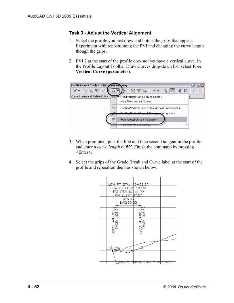
2. PVI 2 at the start of the profile does not yet have a vertical curve. In the Profile Layout Toolbar Draw Curves drop-down list, select Free Vertical Curve (parameter).
3. When prompted, pick the first and then second tangent in the profile, and enter a curve length of 50’. Finish the command by pressing <Enter>.
4. Select the grips of the Grade Break and Curve label at the start of the profile and reposition them as shown below.

Copyrighted Material
Copyrighted
Material
Copyrighted Material
Copyrighted
Material
Alignments and Profiles
© 2008. Do not duplicate. 4 - 53
5. In the Profile Layout toolbar click (Grid View) and the Profile Entities Vista should appear in the Panorama.
6. In Profile Entities Vista, edit the PVI stations, elevations, and curve lengths to match those shown below. (Tip: Fix PVI stations first, set Grades Out to match, and set final PVI elevations and curve lengths.)
7. Pan to the curve at station 45+00. Work with Entity Based data in the Profile Layout toolbar by selecting the following:
8. Click (Select Entity) and select the curve at station 45+00. The Profile Layout Parameters window should be open and the curve’s current length should be 200.
Copyrighted Material
Copyrighted
Material
Copyrighted Material
Copyrighted
Material
AutoCAD Civil 3D 2009 Essentials
4 - 54 © 2008. Do not duplicate.
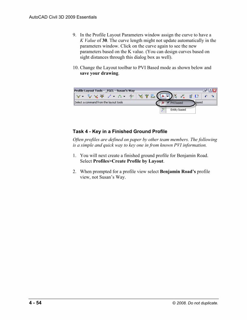
9. In the Profile Layout Parameters window assign the curve to have a K Value of 30. The curve length might not update automatically in the parameters window. Click on the curve again to see the new parameters based on the K value. (You can design curves based on sight distances through this dialog box as well).
10. Change the Layout toolbar to PVI Based mode as shown below and save your drawing.
Task 4 - Key in a Finished Ground Profile Often profiles are defined on paper by other team members. The following is a simple and quick way to key one in from known PVI information.
1. You will next create a finished ground profile for Benjamin Road. Select Profiles>Create Profile by Layout.
2. When prompted for a profile view select Benjamin Road’s profile view, not Susan’s Way.

Copyrighted Material
Copyrighted
Material
Copyrighted Material
Copyrighted
Material
Alignments and Profiles
© 2008. Do not duplicate. 4 - 55
3. In the Create Profile dialog box enter the following and click OK.
4. In the Profile Layout toolbar click (Insert PVIs Tabular). For this
command to be active you must be in PVI-based data mode ( ).
5. In the Insert PVIs dialog box select the Parabolic curve type and enter the following values starting at station 10+11.

Copyrighted Material
Copyrighted
Material
Copyrighted Material
Copyrighted
Material
AutoCAD Civil 3D 2009 Essentials
4 - 56 © 2008. Do not duplicate.
6. When done, click OK and the profile should resemble the following:
Note: The finish ground centerline was drawn in all three views for Benjamin Road.
7. Select the Top View, right-click and select Profile View Properties. In the Profiles tab, clear the FGCL checkbox in the Draw column. Do the same for the bottom view.
8. Save your drawing.
Task 5 - Update Profile Bands 1. The profile views are showing existing ground elevations in both the
existing and proposed slots in the profile bands.

Copyrighted Material
Copyrighted
Material
Copyrighted Material
Copyrighted
Material
Alignments and Profiles
© 2008. Do not duplicate. 4 - 57
2. To update, select the Susan’s Way profile view, right-click and select Profile View Properties. In the Bands tab, assign Profile2 to reference _FGCL – Susan’s Way. Click OK to close.
3. Repeat for the Benjamin Road profile view.
4. Save your drawing.

Copyrighted Material
Copyrighted
Material
Copyrighted Material
Copyrighted
Material
AutoCAD Civil 3D 2009 Essentials
4 - 58 © 2008. Do not duplicate.
Self Check: Profiles
1. Can you safely relocate profile views in AutoCAD Civil 3D using the AutoCAD Move command?
2. Name the three types of vertical curves.
3. Which grip do you use to move the PVI to a new station and/or elevation?
4. What do Profiles 1 and 2 annotate in profile bands?