Embed Size (px)
Citation preview
AutoCAD 2D I
Module 16
Isometric and Dimensioning
PREPARED BY
IAT Curriculum Unit
January 2011
© Institute of Applied Technology, 2011
AutoCAD 2D-I
Module 16: Isometric and Dimensioning 2
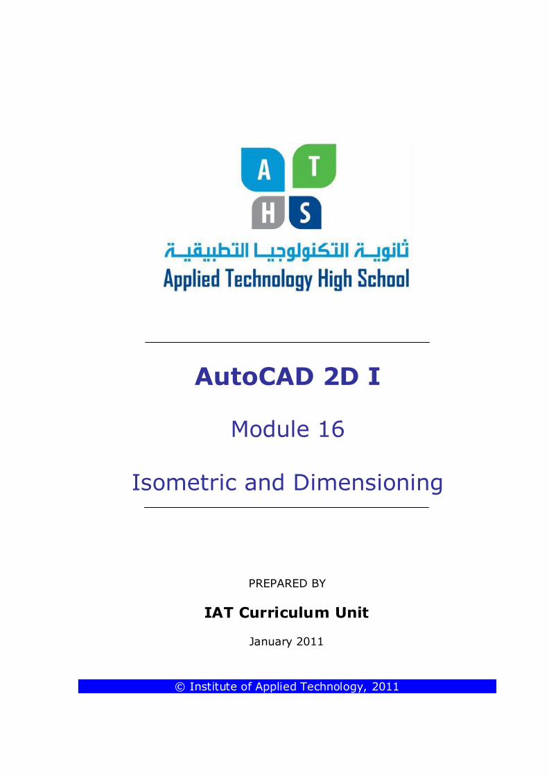
Isometric Projection Isometric drawings consist of two-dimensional drawings that are tilted at some angle to expose other views and give the viewer the illusion that what he or she is viewing
is a three-dimensional drawing. The ti lting occurs with two 30° angles that are struck from the intersection of a horizontal baseline and a vertical line (see Figure 16–1).The directions formed by the 30° angles represent actual dimensions of the
object; this may be either the width or depth. The vertical line in most cases represents the
height dimension.
An Isometric Drawing
Figure 16-1
Auto CAD Self-paced Learning Modules
AutoCAD 2D
Isometric and Dimensioning
Module 16
Learning Outcomes:
When you have completed the module, you will be able to:
1. recognize isometric and oblique drawings.
2. sketch isometric and oblique drawings of simple components.
3. Describe the basic dimensions terms.
4. Describe how to control and modify the appearance of dimensions.
AutoCAD 2D-I
Module 16: Isometric and Dimensioning 3
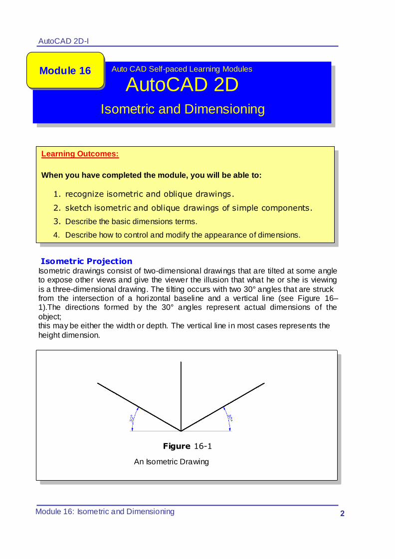
Figure 16–2 is a very simple example of how an object is aligned to the isometric axis.
Figure 16-2
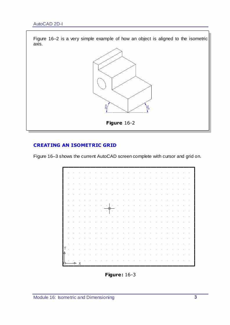
CREATING AN ISOMETRIC GRID
Figure 16–3 shows the current AutoCAD screen complete with cursor and grid on.
Figure: 16-3
AutoCAD 2D-I
Module 16: Isometric and Dimensioning 4
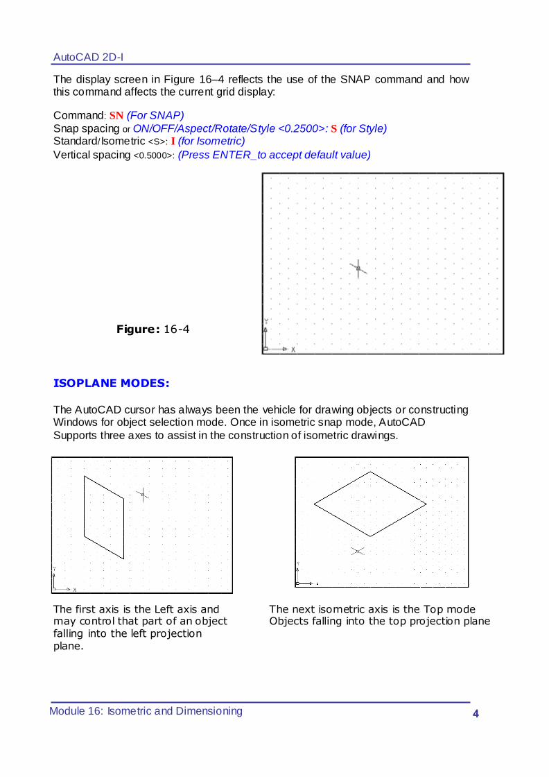
The display screen in Figure 16–4 reflects the use of the SNAP command and how this command affects the current grid display:
Command: SN (For SNAP)
Snap spacing or ON/OFF/Aspect/Rotate/Style <0.2500>: S (for Style)
Standard/ Isometric <S>: I (for Isometric)
Vertical spacing <0.5000>: (Press ENTER_to accept default value)
Figure: 16-4
ISOPLANE MODES:
The AutoCAD cursor has always been the vehicle for drawing objects or constructing Windows for object selection mode. Once in isometric snap mode, AutoCAD
Supports three axes to assist in the construction of isometric drawings.
The first axis is the Left axis and The next isometric axis is the Top mode may control that part of an object Objects falling into the top projection plane falling into the left projection plane.
AutoCAD 2D-I
Module 16: Isometric and Dimensioning 5
Figure A–16A Figure A–16B
Figure A–13A Figure A–13B
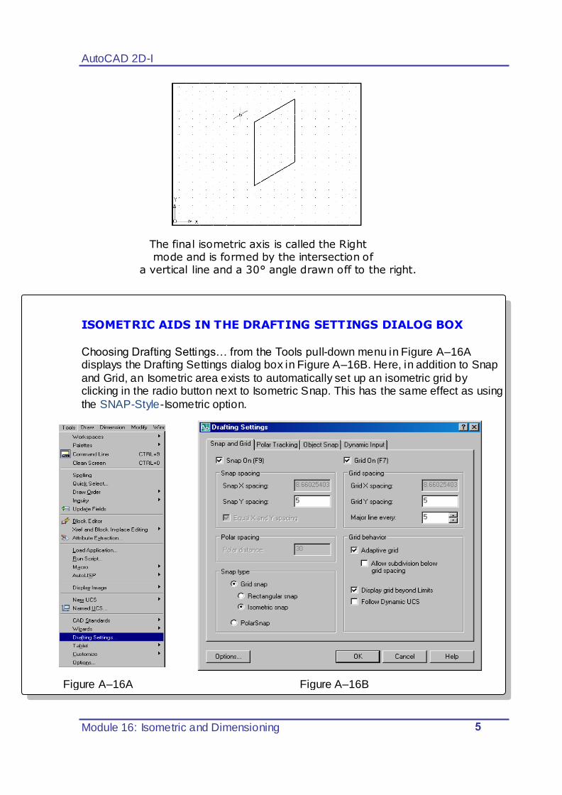
The final isometric axis is called the Right
mode and is formed by the intersection of a vertical line and a 30° angle drawn off to the right.
ISOMETRIC AIDS IN THE DRAFTING SETTINGS DIALOG BOX
Choosing Drafting Settings… from the Tools pull-down menu in Figure A–16A displays the Drafting Settings dialog box in Figure A–16B. Here, in addition to Snap
and Grid, an Isometric area exists to automatically set up an isometric grid by clicking in the radio button next to Isometric Snap. This has the same effect as using
the SNAP-Style-Isometric option.
AutoCAD 2D-I
Module 16: Isometric and Dimensioning 6
Various methods exist to switch from one isometric axis mode to another. By default, after you set up an isometric grid, the Left isometric axis mode is active. When you press CTRL+E, the Left axis mode changes to the Top axis mode. Pressing CTRL+E again changes from the Top axis mode to the Right axis mode. Pressing CTRL+E a third time changes from the Right axis mode back to the Left
axis mode, and the pattern repeats from here. Using this keyboard entry, it is possible to
switch or toggle from one mode to another. The F5 function key also allows you to scroll through the different Isoplane modes.
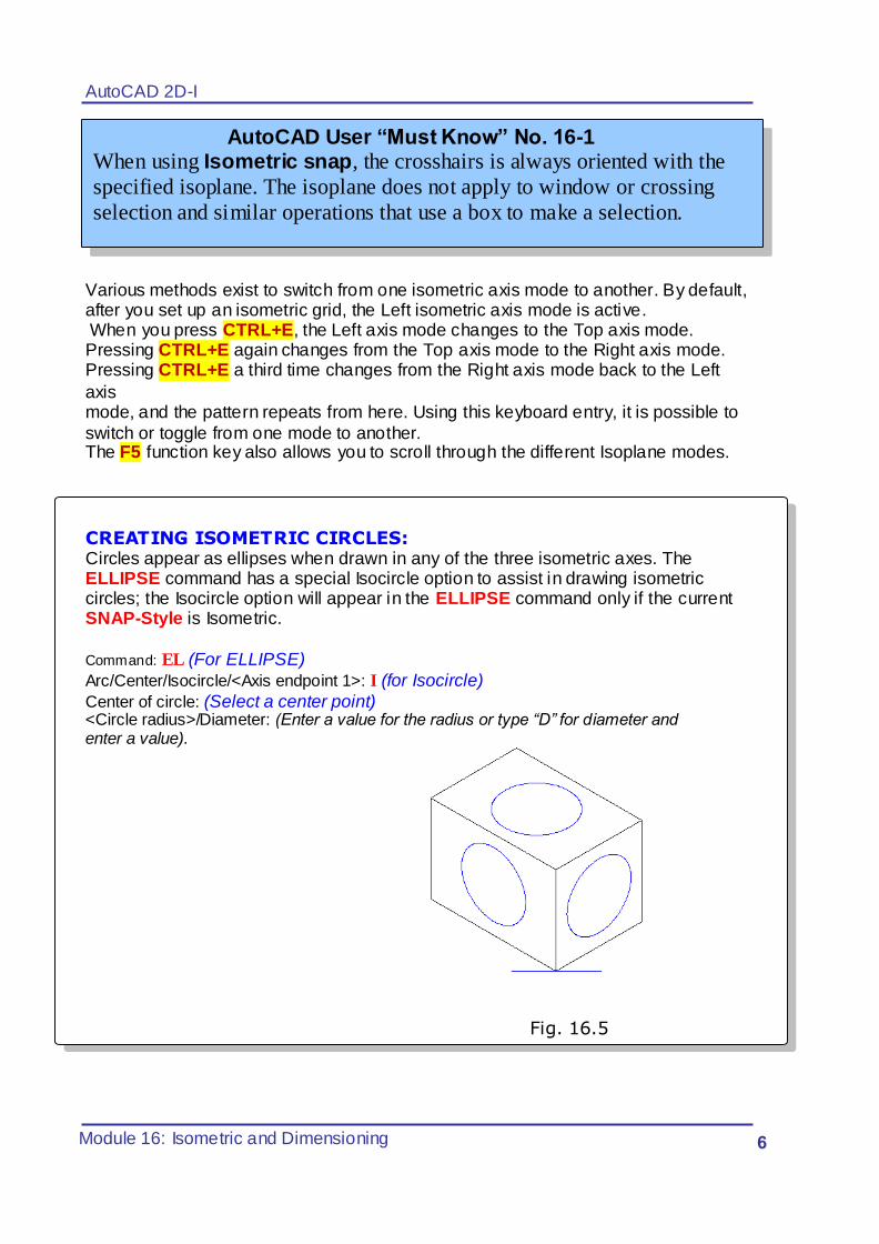
CREATING ISOMETRIC CIRCLES: Circles appear as ellipses when drawn in any of the three isometric axes. The ELLIPSE command has a special Isocircle option to assist in drawing isometric circles; the Isocircle option will appear in the ELLIPSE command only if the current SNAP-Style is Isometric.
Command: EL (For ELLIPSE)
Arc/Center/Isocircle/<Axis endpoint 1>: I (for Isocircle)
Center of circle: (Select a center point)
<Circle radius>/Diameter: (Enter a value for the radius or type “D” for diameter and enter a value).
Fig. 16.5
AutoCAD User “Must Know” No. 16-1 When using Isometric snap, the crosshairs is always oriented with the
specified isoplane. The isoplane does not apply to window or crossing
selection and similar operations that use a box to make a selection.
AutoCAD 2D-I
Module 16: Isometric and Dimensioning 7
1.5
1.8
0.5
1.5
0.5
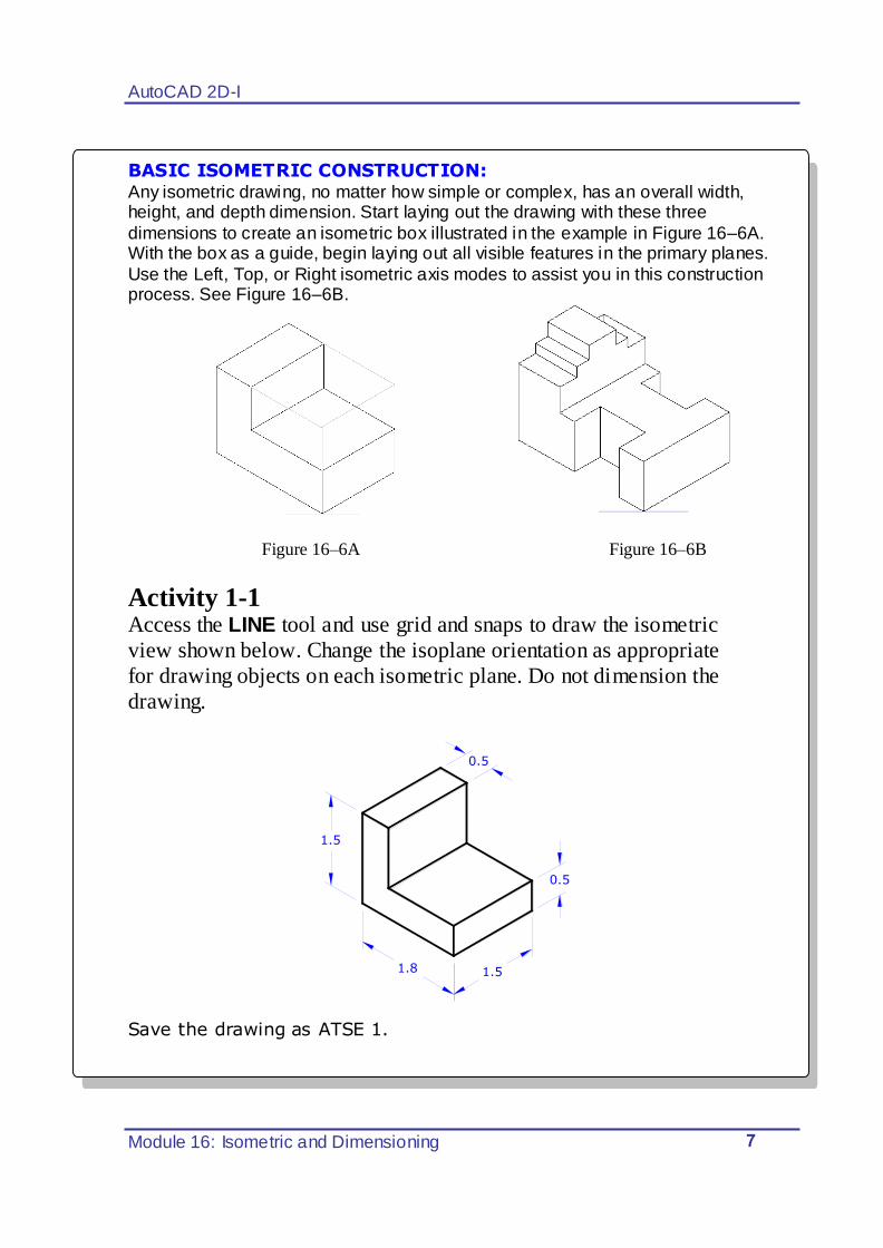
BASIC ISOMETRIC CONSTRUCTION: Any isometric drawing, no matter how simple or complex, has an overall width, height, and depth dimension. Start laying out the drawing with these three
dimensions to create an isometric box illustrated in the example in Figure 16–6A. With the box as a guide, begin laying out all visible features in the primary planes.
Use the Left, Top, or Right isometric axis modes to assist you in this construction process. See Figure 16–6B.
Figure 16–6A Figure 16–6B
Activity 1-1
Access the LINE tool and use grid and snaps to draw the isometric
view shown below. Change the isoplane orientation as appropriate
for drawing objects on each isometric plane. Do not dimension the
drawing.
Save the drawing as ATSE 1.
AutoCAD 2D-I
Module 16: Isometric and Dimensioning 8
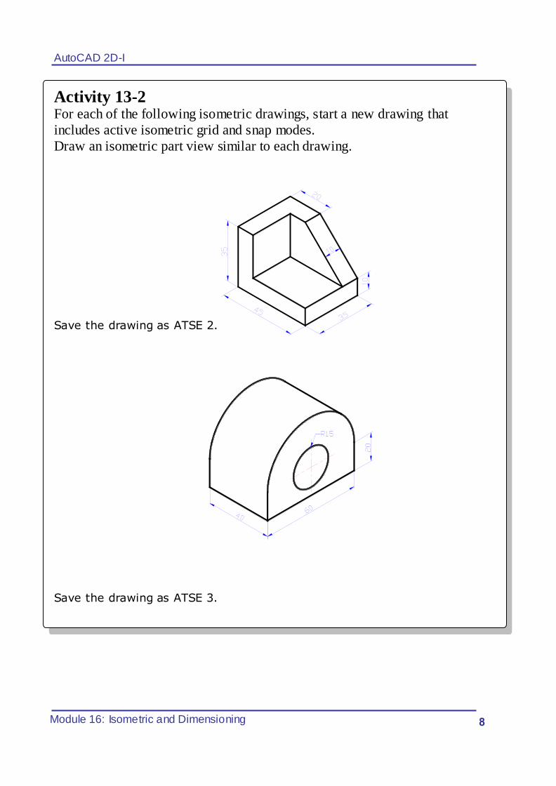
Activity 13-2
For each of the following isometric drawings, start a new drawing that
includes active isometric grid and snap modes.
Draw an isometric part view similar to each drawing.
Save the drawing as ATSE 2.
Save the drawing as ATSE 3.
AutoCAD 2D-I
Module 16: Isometric and Dimensioning 9
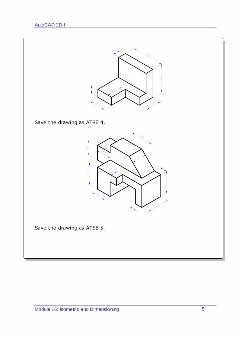
Save the drawing as ATSE 4.
Save the drawing as ATSE 5.
AutoCAD 2D-I
Module 16: Isometric and Dimensioning 01
Dimensioning AutoCAD does semi-automatic dimensioning You select the features which should be dimensioned and the location for each
dimension AutoCAD measures the distance in question and applies the appropriate
dimension complete with arrowheads, extension lines, and dimension lines The Dimensioning Toolbar:
The dimensioning commands can be easily accessed by:
Right Click on an existing toolbar and activate the dimensioning toolbar; Or, From the “pull down” menu
View Toolbars.
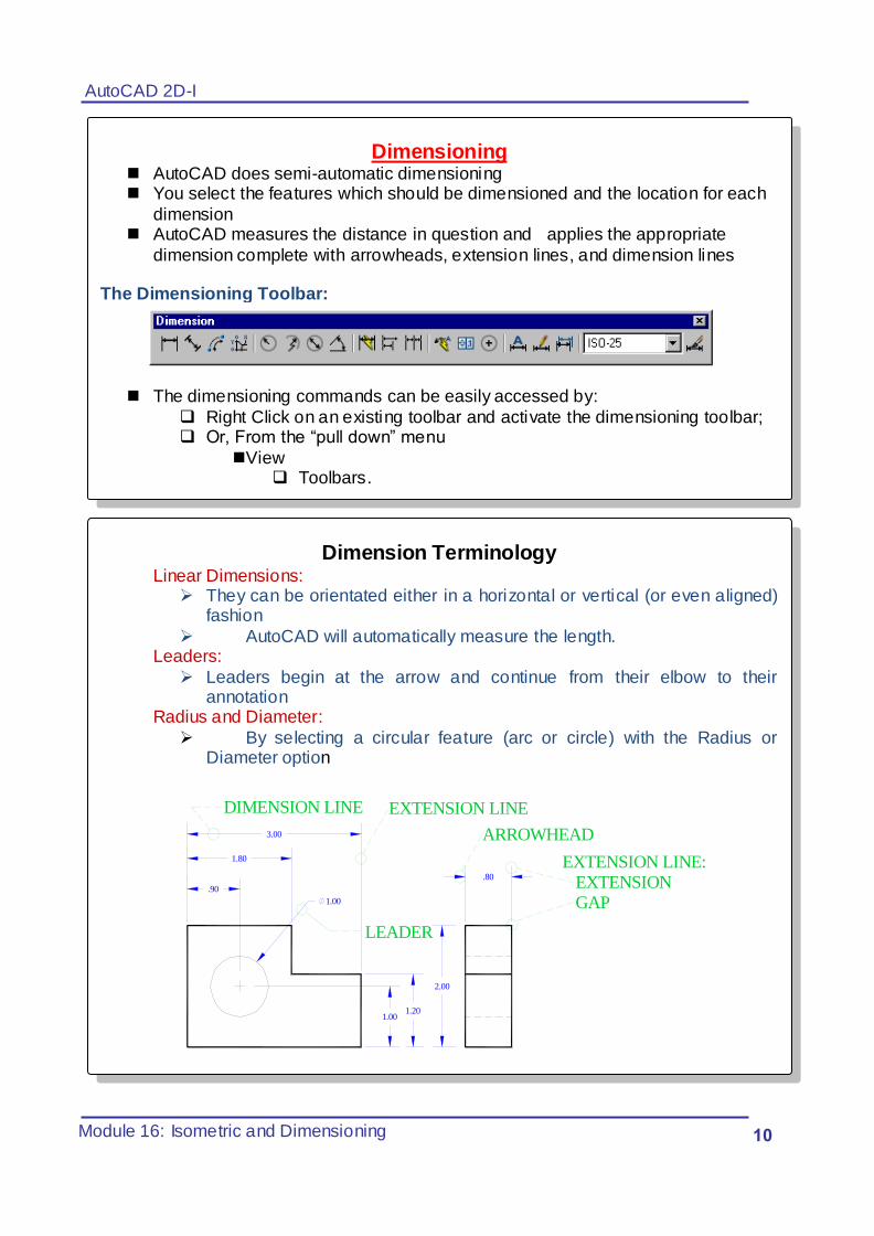
Dimension Terminology
Linear Dimensions: They can be orientated either in a horizontal or vertical (or even aligned)
fashion
AutoCAD will automatically measure the length. Leaders:
Leaders begin at the arrow and continue from their elbow to their annotation
Radius and Diameter:
By selecting a circular feature (arc or circle) with the Radius or Diameter option
1.201.00
LEADER
EXTENSION LINE
1.80
1.00
.90
DIMENSION LINE
EXTENSION LINE: EXTENSION GAP
2.00
.80
ARROWHEAD3.00
AutoCAD 2D-I
Module 16: Isometric and Dimensioning 00
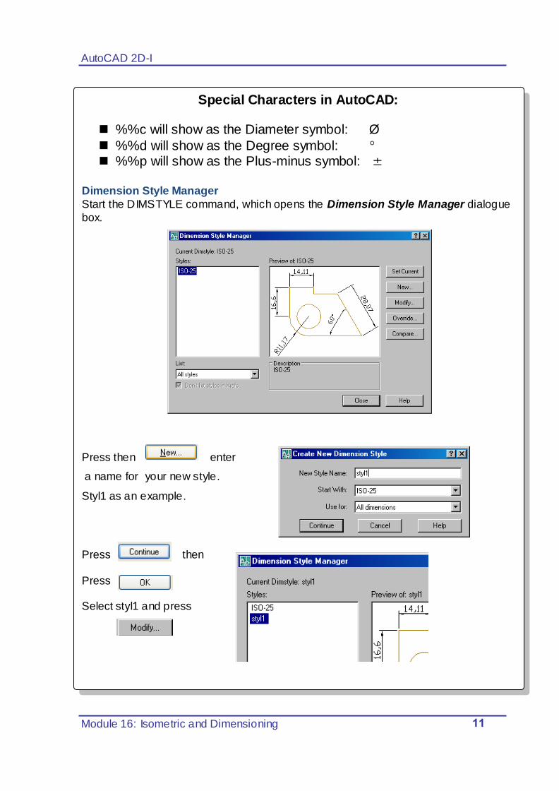
Special Characters in AutoCAD: %%c will show as the Diameter symbol: Ø
%%d will show as the Degree symbol: %%p will show as the Plus-minus symbol:
Dimension Style Manager
Start the DIMSTYLE command, which opens the Dimension Style Manager dialogue
box.
Press then enter
a name for your new style.
Styl1 as an example.
Press then
Press Select styl1 and press
AutoCAD 2D-I
Module 16: Isometric and Dimensioning 02
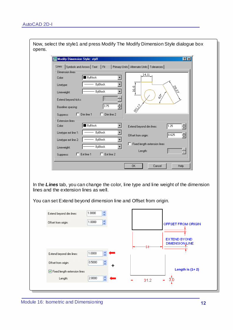
Now, select the style1 and press Modify The Modify Dimension Style dialogue box opens.
In the Lines tab, you can change the color, line type and line weight of the dimension lines and the extension lines as well.
You can set Extend beyond dimension line and Offset from origin.
+ The Length is (1+ 2)
AutoCAD 2D-I
Module 16: Isometric and Dimensioning 03
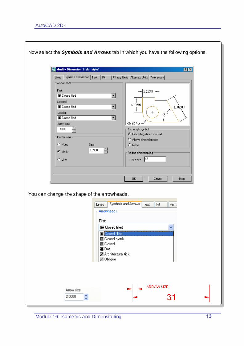
Now select the Symbols and Arrows tab in which you have the following options.
You can change the shape of the arrowheads.
AutoCAD 2D-I
Module 16: Isometric and Dimensioning 04
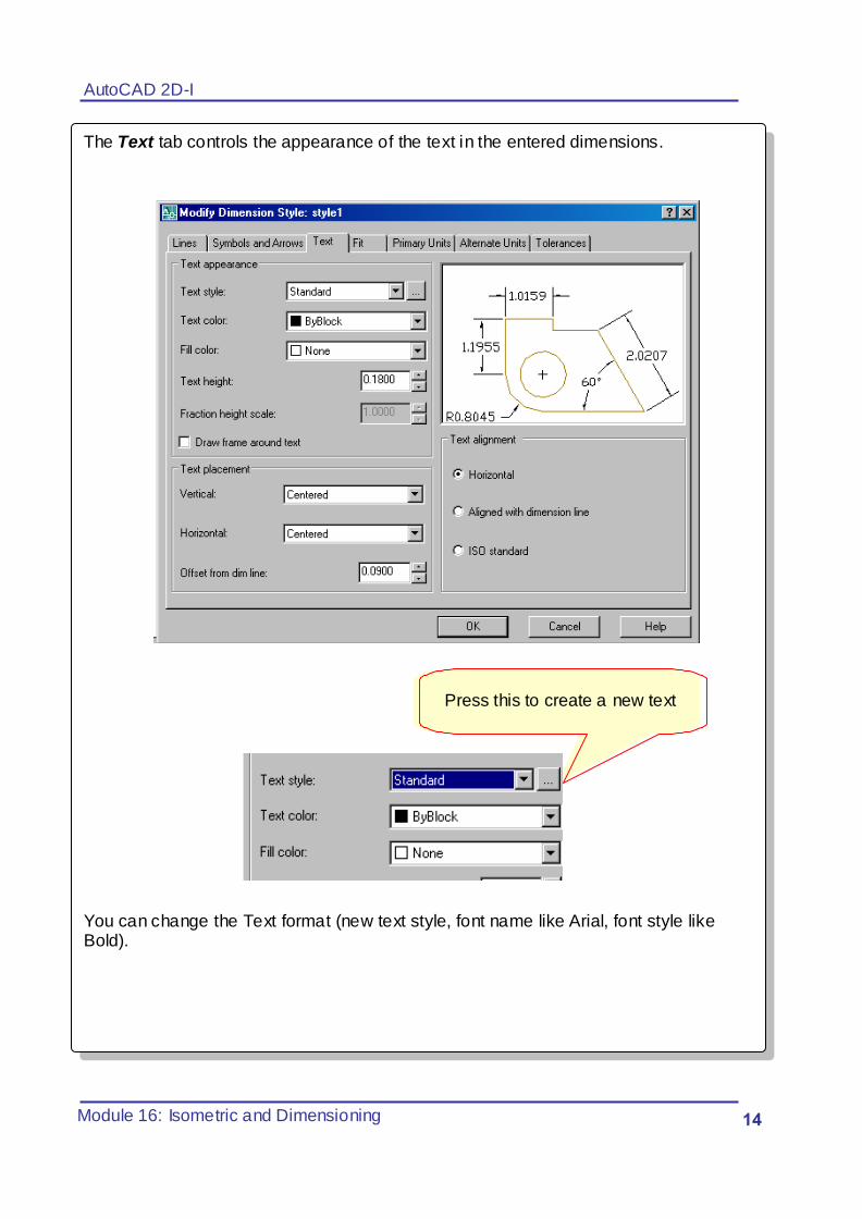
The Text tab controls the appearance of the text in the entered dimensions.
You can change the Text format (new text style, font name like Arial, font style like Bold).
Press this to create a new text
AutoCAD 2D-I
Module 16: Isometric and Dimensioning 05
3. Summary Module 7
1. An isometric drawing is a 2-dimensional drawing that has the XYZ axis drawn 120 degrees apart.
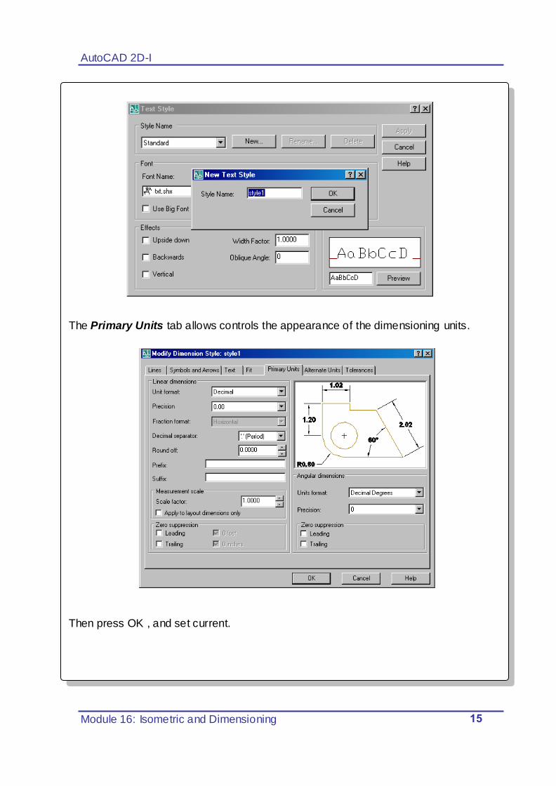
The Primary Units tab allows controls the appearance of the dimensioning units.
Then press OK , and set current.
AutoCAD 2D-I
Module 16: Isometric and Dimensioning 06
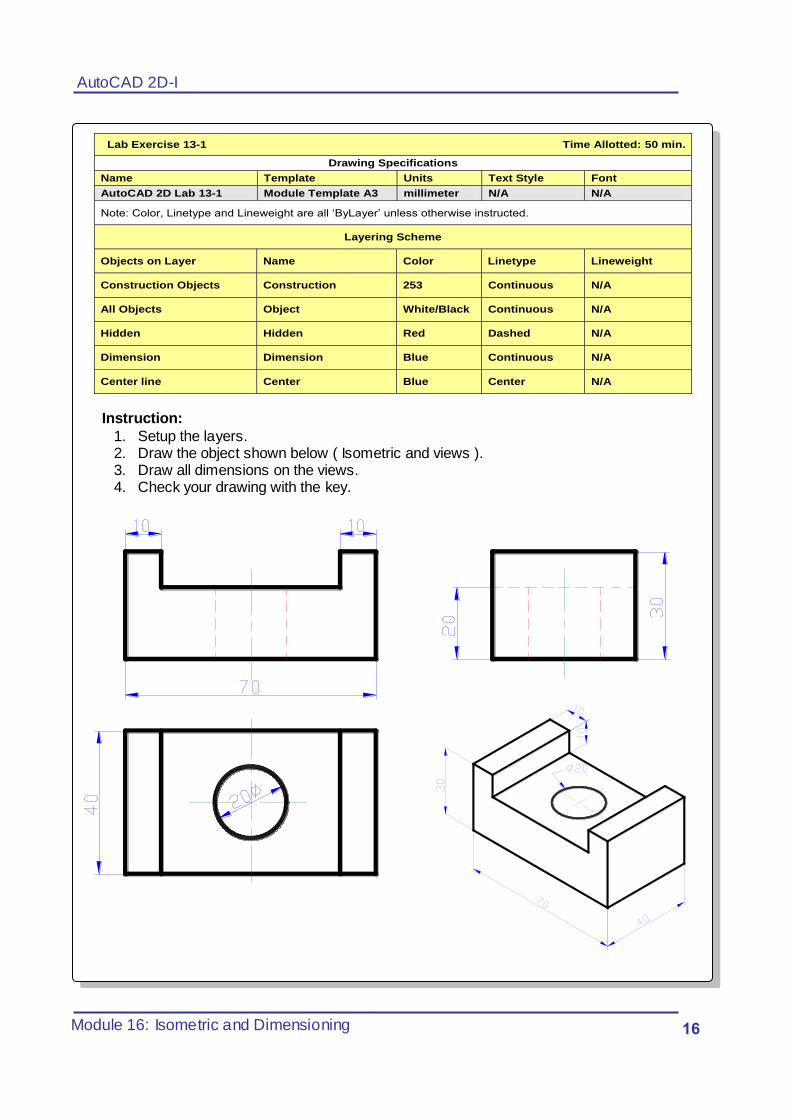
Lab Exercise 13-1 Time Allotted: 50 min.
Drawing Specifications
Name Template Units Text Style Font
AutoCAD 2D Lab 13-1 Module Template A3 millimeter N/A N/A
Note: Color, Linetype and Lineweight are all „ByLayer‟ unless otherwise instructed.
Layering Scheme
Objects on Layer Name Color Linetype Lineweight
Construction Objects Construction 253 Continuous N/A
All Objects Object White/Black Continuous N/A
Hidden Hidden Red Dashed N/A
Dimension Dimension Blue Continuous N/A
Center line Center Blue Center N/A
Instruction:
1. Setup the layers. 2. Draw the object shown below ( Isometric and views ). 3. Draw all dimensions on the views. 4. Check your drawing with the key.

AutoCAD 2D-I
Module 16: Isometric and Dimensioning 07
R5
65
40
60
20
20
10
5
10
15 20
15
30
35
30
40
20
Lab Exercise 13-1 Time Allotted: 50 min.
Drawing Specifications
Name Template Units Text Style Font
AutoCAD 2D Lab 13-1 Module Template A3 millimeter N/A N/A
Note: Color, Linetype and Lineweight are all „ByLayer‟ unless otherwise instructed.
Layering Scheme
Objects on Layer Name Color Linetype Lineweight
Construction Objects Construction 253 Continuous N/A
All Objects Object White/Black Continuous N/A
Hidden Hidden Red Dashed N/A
Dimension Dimension Blue Continuous N/A
Center line Center Blue Center N/A
Instruction:
5. Setup the layers. 6. Draw the object shown below. 7. Draw all dimensions on the views. 8. Check your drawing with the key.
40
60
15
65
40
10
20
10
15
20
30
30
10
? 10
AutoCAD 2D-I
Module 16: Isometric and Dimensioning 08
4. Suggestions for practice
1. What is the correct angle for the drawing of isometric axis?
A. 40°
B. 60° C. 30°
D. 15°
2. A dimension _______ controls the way the dimensions appear in
your drawing.
A. menu
B. style
C. line
D. tool