Embed Size (px)
Citation preview

User's Manual
Release 3.0
Copyright 1993-1994 Autoship Systems CorporationWindows is a trademark of Microsoft Corporation
a u t o s h i pSystems Corporation
Suite 403 Tel • (604) 254-4171
611 Alexander Street Fax • (604) 254-5171
Vancouver • B C
V6A 1E1 • Canada

Table of Contents •• i
TABLE OF CONTENTS
Chapter 1 Getting Started ...............................1
Introducing Autopower...................................................1
Two Versions................................................................2
Package Contents..........................................................2
Autoship Program Suite..................................................3
About this Manual .........................................................5
System Requirements ....................................................6
Installing Autopower ......................................................7
Upgrading from Demo to Full Version ............................. 11
Chapter 2 About Autopower.......................... 13
Entering and Exiting ..................................................... 14
Mouse and Keyboard.................................................... 15
Main Screen ............................................................... 16
Menu System ............................................................. 17
Default Settings .......................................................... 18
Resistance Methods..................................................... 19
Chapter 3 Menu System ............................... 21
File Menu.................................................................... 22
File - Open.......................................................... 22
File - Save .......................................................... 23
File - Save As...................................................... 24
File - Page Setup ................................................. 25
File - Print........................................................... 26
File - Exit ............................................................ 27
Edit Menu ................................................................... 28
Edit - Copy / Paste Cell......................................... 28
Edit - Copy / Paste Column ................................... 29
Edit - Clear Grid................................................... 30
Solve Menu................................................................. 31

ii •• Table of Contents
Solve - Resistance................................................31
Solve - Propulsion ................................................32
Solve - Calculate Now ..........................................33
Solve - Reports ....................................................34
Settings Menu .............................................................35
Settings - Sea / Fresh Water..................................35
Settings - Metric / Imperial ....................................36
Help Menu ..................................................................37
Help - Contents ...................................................38
Help - Using Help .................................................39
Help - About Autopower .......................................40
Chapter 4 Hull Parameters .............................41
Parameters for Displacement & Catamaran Hulls .............42
Parameters for Planing & Semi-Displacement Hulls...........44
Hull Parameter Notes....................................................46
Importing Hull Parameters from Autoship ........................48
Chapter 5 Calculating Resistance....................49
Notes on Calculating Resistance ....................................57
Chapter 6 Propeller Design and Propulsion .......59
Notes on Propeller Design and Propulsion........................66
Chapter 7 Algorithms....................................69
Applicable Limits for Methods........................................71
Algorithms ..................................................................75
Andersen/Guldhammer .........................................75
Fung...................................................................77
Holtrop ...............................................................79
van Oortmerssen .................................................81
Digernes/Cheng ...................................................83
Jin/Su/Tan ..........................................................85

Table of Contents •• iii
Calisal ................................................................ 87
FAO................................................................... 89
Marintek Fastcat ................................................. 91
Compton ............................................................ 93
Savitsky ............................................................. 95
Radojcic ............................................................. 97
B-Series Propellers (MARIN) .......................................... 99
Gawn-Burrill KCA Series ............................................. 101
Ducted Propellers (MARIN) .....................................................103
Index......................................................... 105

Chapter 1 −− Getting Started •• 1
Chapter 1Getting Started
Introducing AutopowerWelcome to Autopower, an intuitive, yet sophisticated resistance andpower prediction program that provides naval architects and designers withindustry standard resistance and power prediction methods fordisplacement, planing, semi-displacement and catamaran vessels. The limitsof each prediction method are clearly displayed, providing guidance on theselection of the most suitable methods. Up to five different hull alternativescan be considered simultaneously, facilitating comparative design studiesand optimization. Parameters can be easily changed for quickrecalculations.
Autopower has a fast link that enables input parameters to be importedfrom our Autoship hull design / surface modeling program. High qualitygraphs and tables can be displayed on-screen or printed, either directly orvia MS Word for customized reports.

Package Contents
2 •• Chapter 1 −− Getting Started
Two VersionsAutopower comes in two versions: Demo version and Full version.
The Demo version is identical to the Full version except that the Demoversion has a 30 day time limit. The Demo version may be upgraded to theFull version by sending in the Upgrade Order Form found at the front ofthis user’s manual.
Package ContentsThe contents of your Autopower package, which are the same for theDemo version and Full version, consist of:
• this user's manual
• a program disk
Contact Autoship Systems Corporation by phone, fax or mail if any itemsare missing from your package.

Autoship Program Suite
Chapter 1 −− Getting Started •• 3
Autoship Program SuiteAutopower is part of our integrated suite of Windows programs.

Autoship Program Suite
4 •• Chapter 1 −− Getting Started
Autoship
Use Autoship to model the hull and superstructure. If installed, you canaccess Autopower from Autoship by selecting Calcs-Autopower.
Autohydro
Use Autohydro to perform complete hydrostatic calculations and analyses.
Autobuild
Use Autobuild to design and model all internal structures.
Autoload
Once your vessel is built, use Autoload as an onboard load and stabilitymonitor.
Contact us or any of our international dealers for more information on anyof our programs.

About This Manual
Chapter 1 −− Getting Started •• 5
About This ManualWe assume you are familiar with the Windows environment. If you havenot worked with Windows before, please consult your Windowsdocumentation. Here is what you will find in this user's manual:
Chapter 1
Getting Started introduces you to Autopower and helps you install it.
Chapter 2
About Autopower tells you how to run Autopower and familiarizes youwith the display, keyboard and Autopower's main functions.
Chapter 3
Menu System provides information on each of Autopower’s menus.
Chapter 4
Hull Parameters describes how to enter hull parameters required toperform resistance calculations.
Chapter 5
Calculating Resistance describes how to calculate resistance.
Chapter 6
Propeller Design and Propulsion describes how to use Autopower’spropeller design options and to calculate propulsion.
Chapter 7
Algorithms describes Autopower’s resistance and propulsion methods.
Index

System Requirements
6 •• Chapter 1 −− Getting Started
System RequirementsMinimum Recommended
CPU 386 DX 25 MHz
with math co-
processor
486 DX2 66 MHz or
Pentium
Memory 8 Mb RAM 16 Mb RAM
Graphics Capability 640x480 resolution,
16-color VGA
monitor with
compatible video
card
1024x768
resolution, 256-
color VGA monitor
with compatible
video card
Free Hard Disk Space 5 Mb
Operating System Windows 3.1 or later version, or Windows
NT
Mouse √
Laser Printer √

Installing Autopower
Chapter 1 −− Getting Started •• 7
Installing Autopower
Before Installation
1. Check the Autopower program disk for the readme.wri andhistory.wri files and read them, if present, with Windows Write.Readme.wri contains the latest comments on the installation procedureand program use. History.wri contains a summary of the programrevisions.
2. Disable floppy disk caching in Smartdrive before starting theinstallation. Otherwise, problems may arise with the Setup program dueto disk buffering. To disable floppy disk caching, type the commandsmartdrv a- b- at the DOS prompt.
3. Ensure that you have enough hard disk space - approximately 5 Mb isrequired.
4. Ensure that your autoexec.bat file has the Windows directory in thepath statement.
5. If you have MS Word, ensure that your autoexec.bat file has the MSWord directory in the path statement. This will enable you to transferAutopower output to MS Word.

Installing Autopower
8 •• Chapter 1 −− Getting Started
Installing Autopower
The installation procedure is the same for the Demo version and Fullversion.
1. Start Windows and open the File Manager.
2. Insert the Autopower program disk into your disk drive.
3. Enter File-Run. The Run dialog box appears. Enter a:\setup.exe orb:\setup.exe, depending on the disk drive you are using. Click OK.Disregard Run Minimized as this is a standard Windows optioninappropriate for Autopower.
4. A Setup box appears while the setup files are being initialized.

Installing Autopower
Chapter 1 −− Getting Started •• 9
5. Then the Autoship Directory Path dialog box appears.
6. Enter the drive and directory where you want to install Autopowerand click OK . To use the default directory setting ofC:\AUTOSHIP\APWR, click OK without entering anything in theinput box.

Installing Autopower
10 •• Chapter 1 −− Getting Started
7. The Product Registration dialog box appears.
8. Enter your first name, last name, and company name as you areprompted. Use the tab key after entering each line. Click OK.
9. The "Application Installation is Complete" message box appears.Click OK .

Installing Autopower
Chapter 1 −− Getting Started •• 11
Note: The first time you run Autopower, the Font dialog box will appearso that you can set the font type and size to be used for printing reports.We recommend using a regular 10-point Arial font. These settings willremain until changed. To change these settings, select File - Page Setupand click on the Fonts button, which will open the Fonts dialog box.
Upgrading from Demo to Full Version
If you have a Demo version, each time you run Autopower, the startupscreen will tell you how many days you have left in your 30 day demoperiod. At the end of the demo period, you will not be able to operateAutopower.
1. Complete the Upgrade Order Form found at the front of this user’smanual and fax or mail it to us. Or, contact us by telephone andprovide us with the full information on the Upgrade Order Form.

Installing Autopower
12 •• Chapter 1 −− Getting Started
2. We will provide you with a 22 character Access Code which willremove the time limitation on your Demo version and make it a Fullversion.
3. Re-install Autopower following the steps under InstallingAutopower. The “Previous Installation Found...Overwrite?”message box appears. Click Yes.
4. The "Please Wait" message box appears followed by the DemoVersion Options dialog box. Select Upgrade to Full Version. Enterthe Access Code. Click OK . If you enter more or less than the 22character Access Code, you will be prompted to re-enter the string.If you enter 22 characters but not the correct Access Code, thesetup program will terminate.
5. The "Installation is Complete" message box appears. Click OK .

Chapter 2 - About Autopower •• 13
Chapter 2About Autopower
This chapter gives you an overview of Autopower and covers the followingpoints:
• Entering and Exiting
• Mouse and Keyboard
• Main Screen
• Menu System
• Default Settings
• Resistance and Propulsion Methods

Entering and Exiting
14 •• Chapter 2 −− About Autopower
Entering and Exiting
Entering Double-click on the Autopower icon.
Alternatively, you can open the File Manager and selectc:\autoship\apwr\apwr.exe.
Exiting Select File - Exit.

Mouse and Keyboard
Chapter 2 - About Autopower •• 15
Mouse and KeyboardIn Autopower, the mouse works the same way as it does in any Windowsprogram. Use the left mouse button for all selecting. The right mousebutton is not used.
Key Use It To
Character Keys Type in names and specify values.
Arrow keys Move through grids.
Enter Accept the entry you have just made.
F1 or Alt + H Open Help menu.
F2 Edit active cell.
F5 Open Resistance dialog box.
F6 Open Propulsion dialog box.
F9 Run resistance calculations.
F12 Open Save-As dialog box.
Control + F12 Open �Save existing data?� dialog box. If you enter Yes,
the Open File dialog box opens.
Shift + F12 Open Save dialog box. If file has not been named yet,
the Save As dialog box opens.
Control + Shift +
F12
Open Print dialog box. If a font has not been selected
yet, the Font dialog box opens.
Alt + F Open File menu.
Alt + E Open Edit menu.
Alt + V Open Solve menu.
Alt + S Open Settings menu.

Main Screen
16 •• Chapter 2 −− About Autopower
Main Screen
Menu System
Chapter 2 - About Autopower •• 17
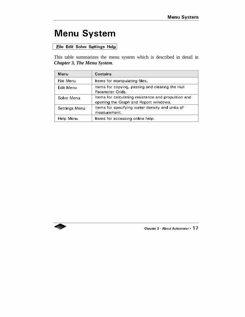
Menu System
This table summarizes the menu system which is described in detail inChapter 3, The Menu System.
Menu Contains
File Menu Items for manipulating files.
Edit Menu Items for copying, pasting and clearing the Hull
Parameter Grids.
Solve Menu Items for calculating resistance and propulsion and
opening the Graph and Report windows.
Settings Menu Items for specifying water density and units of
measurement.
Help Menu Items for accessing online help.
File Edit Solve Settings Help

Default Settings
18 •• Chapter 2 −− About Autopower
Default SettingsAutopower's default settings are as follows:
• Displacement hull type • Metric units • Sea water density • Printing is sent to the default system printer • Pages are 8.5 x 11 inches with page margins 1 inch from all
four sides

Resistance Methods
Chapter 2 - About Autopower •• 19
Resistance MethodsAutopower provides the following resistance methods which are describedin detail in Chapter 5, Calculating Resistance and Chapter 7, Algorithms.
Displacement• Andersen/Guldhammer• Fung• Holtrop• van Oortmerssen• Digernes/Cheng• Jin/Su/Tan• Calisal• FAO
Semi-Displacement• Compton
Planing• Savitsky• Radojcic
Catamaran• Marintek Fastcat

20 •• Chapter 2 −− About Autopower

Chapter 3 −− Menu System •• 21
Chapter 3Menu System
Autopower's menu system consists of File, Edit, Solve, Settings, and Helpmenus.
File Edit Solve Settings Help

Chapter 5 −− Calculating Resistance •• 49
Chapter 5Calculating Resistance
To calculate resistance, take the following steps:
1. Select the hull type.
2. Enter the hull parameters into the Hull Parameter Grid or import thehull parameters from Autoship (see Chapter 4, Hull Parameters).
3. Click on the Resistance icon.
4. The Resistance dialog box opens. This dialog box contains theresistance method(s) appropriate to the hull type you have selected.

Calculating Resistance
50 •• Chapter 5 −− Calculating Resistance
Resistance Dialog Box (Displacement)
5. Select the resistance method(s). You can use the Browse Methods boxto compare the limits of the selected method(s) against the hullparameters of the active file.
6. Click on the Speeds button.

Calculating Resistance
Chapter 5 −− Calculating Resistance •• 51
7. The Speeds dialog box opens. Enter the lower, upper, interval andservice speeds. Click OK .
8. Click on the Options button.
9. The Resistance Options dialog box appears. There are four Optionsdialog boxes, depending on the hull type you have selected.
Resistance Options (Displacement)

Calculating Resistance
52 •• Chapter 5 −− Calculating Resistance
Resistance Options (Semi-Displacement)
Resistance Options (Planing)

Calculating Resistance
Chapter 5 −− Calculating Resistance •• 53
Resistance Options (Catamaran)
10. Enter the following resistance options and click OK .
Option Entry
Hull Wetted
Area
This option is available for all vessel types. You must
enter the hull wetted area either by entering a user-
defined value into the Hull Parameters grid, or by
selecting one of the following methods:
• User Defined (this is the default)
• Haslar
• Denny Mumford
• Holtrop/Mennen (displacement only)
• Averaged
Form Factor
(1+k)
This option is available only for displacement vessels.
You must enter the Form Factor in the Hull Parameters
grid. Once entered, select among:
• User Defined (this is the default)
• Holtrop
• Tagano
Calculating Resistance
54 •• Chapter 5 −− Calculating Resistance
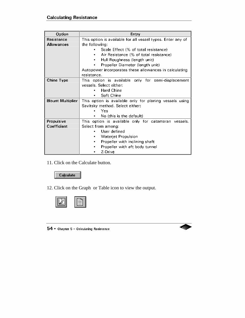
Option Entry
Resistance
Allowances
This option is available for all vessel types. Enter any of
the following:
• Scale Effect (% of total resistance)
• Air Resistance (% of total resistance)
• Hull Roughness (length unit)
• Propeller Diameter (length unit)
Autopower incorporates these allowances in calculating
resistance.
Chine Type This option is available only for semi-displacement
vessels. Select either:
• Hard Chine
• Soft Chine
Blount Multiplier This option is available only for planing vessels using
Savitsky method. Select either:
• Yes
• No (this is the default)
Propulsive
Coefficient
This option is available only for catamaran vessels.
Select from among:
• User defined
• Waterjet Propulsion
• Propeller with inclining shaft
• Propeller with aft body tunnel
• Z-Drive
11. Click on the Calculate button.
12. Click on the Graph or Table icon to view the output.
Calculating Resistance
Chapter 5 −− Calculating Resistance •• 55
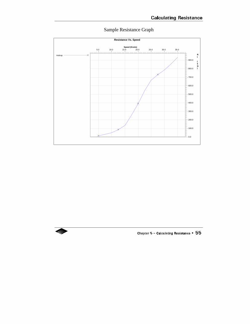
Sample Resistance Graph
Resistance Vs. Speed
Speed (Knots)
Rt (kN)
5.0 10.0 15.0 20.0 25.0 30.0 35.0
0.0
100.0
200.0
300.0
400.0
500.0
600.0
700.0
800.0
900.0
Holtrop

Calculating Resistance
56 •• Chapter 5 −− Calculating Resistance
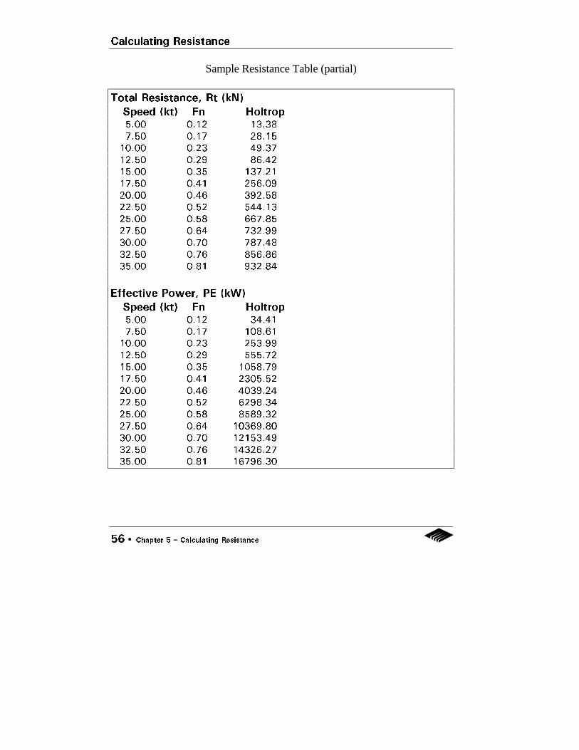
Sample Resistance Table (partial)
Total Resistance, Rt (kN)
Speed (kt) Fn Holtrop5.00 0.12 13.38
7.50 0.17 28.15
10.00 0.23 49.37
12.50 0.29 86.42
15.00 0.35 137.21
17.50 0.41 256.09
20.00 0.46 392.58
22.50 0.52 544.13
25.00 0.58 667.85
27.50 0.64 732.99
30.00 0.70 787.48
32.50 0.76 856.86
35.00 0.81 932.84
Effective Power, PE (kW)
Speed (kt) Fn Holtrop5.00 0.12 34.41
7.50 0.17 108.61
10.00 0.23 253.99
12.50 0.29 555.72
15.00 0.35 1058.79
17.50 0.41 2305.52
20.00 0.46 4039.24
22.50 0.52 6298.34
25.00 0.58 8589.32
27.50 0.64 10369.80
30.00 0.70 12153.49
32.50 0.76 14326.27
35.00 0.81 16796.30
Calculating Resistance
Chapter 5 −− Calculating Resistance •• 57
Notes on Calculating Resistance
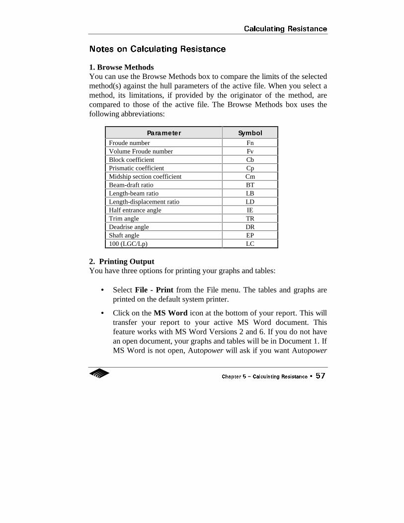
1. Browse MethodsYou can use the Browse Methods box to compare the limits of the selectedmethod(s) against the hull parameters of the active file. When you select amethod, its limitations, if provided by the originator of the method, arecompared to those of the active file. The Browse Methods box uses thefollowing abbreviations:
Parameter SymbolFroude number FnVolume Froude number FvBlock coefficient CbPrismatic coefficient CpMidship section coefficient CmBeam-draft ratio BTLength-beam ratio LBLength-displacement ratio LDHalf entrance angle IETrim angle TRDeadrise angle DRShaft angle EP100 (LGC/Lp) LC
2. Printing OutputYou have three options for printing your graphs and tables:
• Select File - Print from the File menu. The tables and graphs areprinted on the default system printer.
• Click on the MS Word icon at the bottom of your report. This willtransfer your report to your active MS Word document. Thisfeature works with MS Word Versions 2 and 6. If you do not havean open document, your graphs and tables will be in Document 1. IfMS Word is not open, Autopower will ask if you want Autopower

Calculating Resistance
58 •• Chapter 5 −− Calculating Resistance
to open MS Word. If Autopower cannot locate MS Word, it willprompt you enter the proper path.
• Click on the Copy icon at the bottom of your report. Thistransfers your report to the Clipboard. Use the Paste function inyour word processing or spreadsheet program to paste yourreport. To see a copy of your report in the Clipboard, click on theClipboard Viewer icon in the Windows Program Manager screen(usually in the Main directory box).

File - Open
22 •• Chapter 3 −− Menu System
File - Open
Use It To Load an Autopowerfile (denoted with.pwr extension) intothe Hull ParameterGrid.
Quick Keys Control + F12 or Alt + FO
How It Works Select File-Open. The Open dialog box appears.Select the desired file. Click OK .

File - Save
Chapter 3 −− Menu System •• 23
File - Save
Use It To Save all the changesyou have made tothe active file.
Quick Keys Shift + F12 or Alt + FS
How It Works Select File - Save to save all the changes you havemade to the active file. If the file has not been namedyet, the Save As dialog box opens.
Note: Since Autopower saves only the active file, we recommend that yousave your work before you switch vessel types (eg. from a displacement toplaning vessel).

File - Save As
24 •• Chapter 3 −− Menu System
File - Save As
Use It To Save a copy of theactive file with anew name.
Quick Keys F12 or Alt + FA
How It Works Select File - Save As. The Save As dialog boxappears. Select the file name and directory. ClickOK .

File - Page Setup
Chapter 3 −− Menu System •• 25
File - Page Setup
Use It To Set up pagemargins, size, fontand printer.
Quick Key Alt + FG
How It Works Select Settings - Page Setup. The Page Setupdialog box appears. Select the desired page size,font and printer. Click OK .
File - Print
26 •• Chapter 3 −− Menu System
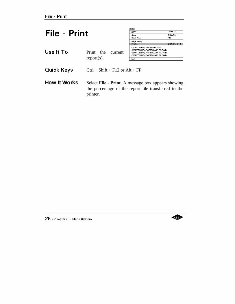
File - Print
Use It To Print the currentreport(s).
Quick Keys Ctrl + Shift + F12 or Alt + FP
How It Works Select File - Print. A message box appears showingthe percentage of the report file transferred to theprinter.

File - Exit
Chapter 3 −− Menu System •• 27
File - Exit
Use It To Exit Autopower.
Quick Key Alt + FX
How It Works Select File - Exit. If you have an open file, the SaveProject message box appears. Click Yes or No, asappropriate.

Edit - Copy / Paste Cell
28 •• Chapter 3 −− Menu System
Edit - Copy Cell
- Paste Cell
Use Them To Copy data from one cell to another.
Quick Keys Alt + EC and Alt + EP
How They Work Click on the cell you want to copy. Select Edit -Copy Cell. Then click on the cell you want topaste it to. Select Edit - Paste Cell. The data inthe original cell is now copied to the new cell.

Edit - Copy / Paste Column
Chapter 3 −− Menu System •• 29
Edit - Copy Column
- Paste Column
Use Them To Copy data from one column toanother.
Quick Keys Alt + EO and Alt ES
How They Work Click on the column you want to copy. Select Edit- Copy Column. Then click on the column youwant to paste it to. Select Edit - Paste Column.The data in the original column is now copied tothe new column.

Edit - Clear Grid
30 •• Chapter 3 −− Menu System
Edit - Clear Grid
Use It To Clear the Hull Parameter Grid.
Quick Key Alt + EG
How It Works Select Edit - Clear Grid . A message box appearsasking you to affirm that you want to clear the grid.Click Yes or No, as appropriate.

Solve - Resistance
Chapter 3 −− Menu System •• 31
Solve - Resistance
Use It To Open the Resistance dialogbox. This is equivalent toclicking on the Resistance icon.
Quick Keys Control + F5 or Alt + VR
How It Works Select Solve - Resistance. The Resistance dialogbox appears. Enter all required information. (SeeChapter 5, Calculating Resistance.)

Solve - Propulsion
32 •• Chapter 3 −− Menu System
Solve - Propulsion
Use It To Open the Propulsion dialogbox. This is equivalent toclicking on the Propulsion icon.
Quick Keys Control + F6 or Alt + VP
How It Works Select Solve - Propulsion. The Propulsion dialogbox appears. Enter all required information. (SeeChapter 6, Propeller Design and Propulsion.)
Solve - Calculate Now
Chapter 3 −− Menu System •• 33
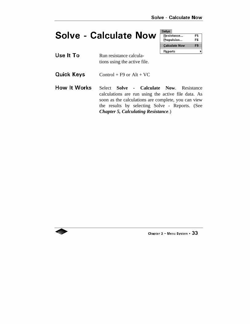
Solve - Calculate Now
Use It To Run resistance calcula-tions using the active file.
Quick Keys Control + F9 or Alt + VC
How It Works Select Solve - Calculate Now. Resistancecalculations are run using the active file data. Assoon as the calculations are complete, you can viewthe results by selecting Solve - Reports. (SeeChapter 5, Calculating Resistance.)

Solve - Reports
34 •• Chapter 3 −− Menu System
Solve - Reports
Use It To Display and clearreports (graphsand, tables). Selecting Graph or Table from thismenu is the equivalent of clicking on the Graph iconor Table icon.
Quick Key Alt + VE
How It Works Select Solve - Reports - Graph or Table.. TheGraph ot Table window appears. To print yourreports, see the note on printing output at the end ofChapters 5 or 6.
Select Clear All to clear your reports. Otherwise,successive graphs and tables will be added to allthose generated since the last Clear All command.

Settings - Sea / Fresh Water
Chapter 3 −− Menu System •• 35
Settings - Sea Water
- Fresh Water
Use It To Toggle between Sea water and Fresh Water.
Quick Keys Alt + SS and Alt SF
How It Works Select Settings - Sea Water or Fresh Water. Thedefault setting is Sea Water. The specific gravity ofSea water is 1.026. The specific gravity of Freshwater is 1.0.
Note: All Autopower calculations are based upon a water temperature of15° C.

Settings - Metric / Imperial
36 •• Chapter 3 −− Menu System
Settings - Metric
- Imperial
Use It To Toggle between metric or imperial units.
Quick Keys Alt + SM and Alt + SI
How It Works Select Settings - Metric or Imperial . The defaultsetting is metric. The selected units appear at theright side of the Hull Parameters Grid.
Standard Units
Measurement Metric Units Imperial Units
Length m ft
Area m2 ft2
Volume m3 ft3
Displacement tonnes LT
Force kN lbs
Power kW hp
Density t/m3 lb/ft3
Velocity m/sec ft/sec
Angles degrees degrees
Ship speed knots knots
Gravitational constant 9.81 m/sec2 32.20 ft/sec2

Help Menu
Chapter 3 −− Menu System •• 37
Help Menu
Quick Key Alt + H
The Help menu contains information about Autopower and lets you accessAutopower's on-line help.

Help - Contents
38 •• Chapter 3 −− Menu System
Help - Contents
Use It To Display the on-line help table ofcontents.
Quick Key Alt + HC
How It Works Select Help - Contents. The on-line help Table ofContents appears. Click on any topic you want toview. To return to Autopower, select File - Exit orclose the Help window.

Help - Using Help
Chapter 3 −− Menu System •• 39
Help - Using Help
Use It To Learn how to use Windows help.
Quick Key Alt + HU
How It Works Select Help - Using Help. A help topic on UsingHelp appears. To return to Autopower, select File -Exit .

Help - About Autopower
40 •• Chapter 3 −− Menu System
Help - About
Autopower
Use It To Display the opening screen.
Quick Key Alt + HA
How It Works Select Help - About Autopower. The openingscreen appears. This screen shows the releasenumber, registered user and serial number. You willneed this information to upgrade from a Demo to aFull version. Click anywhere on the screen to returnto Autopower.

Chapter 4 −− Hull Parameters •• 41
Chapter 4Hull Parameters
Autopower has two Hull Parameter Grids for:
• displacement and catamaran hulls• planing and semi-displacement hulls
The Hull Parameter Grid plays an important role in all Autopower worksessions. All hull parameters must be entered unless otherwise noted in thefollowing tables. When you click on any hull parameter, a brief descriptionof that parameter appears in an information box at the bottom of the MainScreen.

Displacement & Catamaran Hull Parameters
42 •• Chapter 4 −− Hull Parameters
Parameters for Displacement & Catamaran Hulls
Parameter Description Range
Project Name Project name.
LWL Length on waterline.
Breadth Breadth measured midship at design
waterline.
Draft (F) Draft forward measured at the forward
perpendicular.
Draft (A) Draft aft measured at the aft
perpendicular.Displacement Displacement weight.LCB Longitudinal center of buoyancy
measured as a percentage of LBP from
midship. Positive = forward, negative =
aft.
-50 - 50%
CWP Waterplane area coefficient. 0 - 1
CM Midship section coefficient. 0 - 1
Form Factor Form factor [1+k]. Default=1.
(Optional - this parameter can also be
entered in Resistance Options.)
1 - 2
Wetted Hull Area Wetted hull surface area, excluding
appendages.
(Optional - this parameter can also be
estimated in Resistance Options.)
Wetted
Appendage Area
Total surface area of all wetted
appendages.(Enter if there are wetted appendages.)
Wetted Transom
Area
Wetted transom surface area.
(Enter if there is a wetted transom.)
Transom Width Transom width at waterline.
(Required only for Fung method.)
Half Angle of
Entrance
Half angle of entrance in degrees.
(Optional - will be estimated if not
specified.)
0 - 60°
(continued...)

Displacement & Catamaran Hull Parameters
Chapter 4 −− Hull Parameters •• 43
(...continued)Parameters for Displacement & Catamaran Hulls
Parameter Description Range
Half Angle of Run Half angle of run in degrees.
(Required only for FAO method.)
0 - 60°
Angle at 1/4
Buttock
Angle at 1/4 buttock in degrees.
(Required only for FAO method.)
0 - 60°
Bulbous Bow? Bulbous bow? Yes / No Default is No.
Transverse
Bulb Area
Transverse sectional area of bulb at
forward perpendicular.
(Enter if there is a bulbous bow.)
Bulb Centroid
Location
Centroid location of bulb above keel.
(Enter if there is a bulbous bow.)
Body Type - (F) Hull form type forward of midship.
U-shaped, N (Normal), or V-shaped.
Body Type - (A) Hull form type aft of midship.
U, N, or V.
Service Margin User-specified resistance margin.
(Optional.)
0% - 50%
Appendage
Margin
User-specified resistance margin for
appendages.
(Optional.)
0% - 30%
Appendage Form
Factor
Effective form factor [1 + K2] for
appendages. See note below.
(Required only for Holtrop method.)
1 - 4
CB Block coefficient.
(Read only - calculated by Autopower.)
CP Longitudinal prismatic coefficient.(Read only - calculated by Autopower.)

Planing & Semi-Displacement Hull Parameters
44 •• Chapter 4 −− Hull Parameters
Parameters for Planing & Semi-Displacement Hulls
Parameter Description Range
Project Name Project name.
LWL Length on waterline.
Breadth Breadth measured midship at design
waterline.
Draft Draft measured at loadline.
Chine Beam Maximum chine beam.
(Enter if there is a chine.)
Chine Length Maximum chine length.
(Enter if there is a chine.)
CX Maximum section coefficient.
(Required only for Savitsky method.)
0 - 1
Displacement Displacement weight.
LCG Longitudinal center of gravity measured
from midship to the aft perpendicular.
Half Angle of
Entrance
Half angle of entrance in degrees.
(Optional - will be estimated if not
specified.)
0 - 60°
Deadrise Angle Deadrise angle at mid-chine length.
(Enter if there is a chine.)
Wetted Hull Area Wetted hull surface area.
Wetted Transom
Area
Wetted transom surface area.
Strut Type Propeller strut configuration.
0 for single, 1 for V.
0 or 1
Shaft Angle Shaft inclination relative to buttock in
degrees.
Shaft Length Length of wetted shaft or strut barrel.
(Enter if there is a wetted shaft or a
strut barrel.)
Shaft Diameter Diameter of wetted shaft or strut barrel.
(Enter if there is a wetted shaft or a
strut barrel.)
(continued...)

Planing & Semi-Displacement Hull Parameters
Chapter 4 −− Hull Parameters •• 45
(continued...)Parameters for Planing & Semi-Displacement Hulls
Parameter Description Range
Projected Area
of Skeg
Transverse projected area of skeg.
(Enter if there is a skeg.)
Number of Sea
Inlets
Number of non-flush sea water inlets.
(Enter if there are sea inlets.)
Projected Area of
Inlets
Frontal projected area of non-flush sea
water inlets. Enter average of frontal
areas if there is more than one inlet and
of different sizes.(Enter if there are sea inlets.)
Rudder Type Type of rudder. See note below.
Rudder Surface
Area
Total rudder surface area.
Flap Chord Length Flap chord length.(Enter if there is a flap.)
Flap Span to
Beam Ratio
Flap span to beam ratio.(Enter if there is a flap.)
0 - 1
Flap Deflection
Angle
Flap deflection angle in degrees.
(Enter if there is a flap.)
0 - 15°
Service Margin User-specified resistance margin.(Optional.)
0 - 50%
Appendage
Margin
User-specified resistance margin for
appendages.
(Optional.)
0 - 30%

Hull Parameter Notes
46 •• Chapter 4 −− Hull Parameters
Hull Parameter Notes
1. Appendage Form FactorAppendage Form Factor [1 + k2] is used by the Holtrop method. This
factor is derived using the wetted area of appendage components andranges from 1 to 4. Default values for all allowances are zero. Thefollowing table shows the approximate [1 + k2] values.
Rudder behind skeg 1.5 - 2.0Rudder behind stern 1.3 - 1.5Twin-screw balance rudders 2.8Shaft brackets 3.0Skeg 1.5 - 2.0Strut bossings 3.0Hull bossings 2.0Shafts 2.0 - 4.0Stabilizer fins 2.8Dome 2.7Bilge keels 1.4
Autopower accepts an equivalent [1 + k2] factor for all appendages
combined, calculated as follows:
(1 + k2)eq = ∑ (1 + k2)i SAPPDi / ∑ SAPPDi
where SAPPDi is the surface area of the ith appendage in question.

Hull Parameter Notes
Chapter 4 −− Hull Parameters •• 47
2. Rudder TypeYou can select one of four rudder types by entering 0, 1, 2, or 3 as shownin the table below. You must also enter a rudder surface area in the HullParameter grid. Otherwise, resistance due to rudders will be zero.
Rudder
Section
Drag
Coefficient
Thickness to
Chord Ratio
Enter
NACA 0015 0.0013 0 - 15 0
Parabolic 0.0426 0 - 11 1
Flat Plate 0.0352 0 - 04 2
Wedge 0.0493 0 - 11 3
3. Autopower FilesEach file contains one hull type. This means that all of the projects withinone file must be of the same hull type, although individual projects may bein either metric or imperial units.
4. Saving Autopower FilesAutopower saves only the data in the currently displayed grid. For example,if you have been working on the displacement grid and then switch to theplaning grid, the File - Save operation will result in a file containing dataconcerning the planing grid only (which may or may not contain any data).Each hull type grid should be saved to a different file.

Hull Parameter Notes
48 •• Chapter 4 −− Hull Parameters
5. Importing Hull Parameters from AutoshipYou can import certain hull parameters from Autoship to Autopower. Youmay be required to enter further hull parameters in Autopower beforeundertaking calculations.
1. In Autoship, select Calcs - Autopower. The Autopower Setupdialog box appears. Enter file name, hull type and draft value beingused in Autoship. Click OK .
Note: The draft value you must use is the distance from V=0 tothe waterline. For instance, if you define the waterline to be atV=0, then draft is zero.
2. An Open File window then appears. Enter the file name. Click OK .
Note: Autoship uses a demi-hull for catamarans. This should be taken intoaccount in undertaking calculations.

Chapter 5 −− Calculating Resistance •• 49
Chapter 5Calculating Resistance
To calculate resistance, take the following steps:
1. Select the hull type.
2. Enter the hull parameters into the Hull Parameter Grid or import thehull parameters from Autoship (see Chapter 4, Hull Parameters).
3. Click on the Resistance icon.
4. The Resistance dialog box opens. This dialog box contains theresistance method(s) appropriate to the hull type you have selected.

Calculating Resistance
50 •• Chapter 5 −− Calculating Resistance
Resistance Dialog Box (Displacement)
5. Select the resistance method(s). You can use the Browse Methods boxto compare the limits of the selected method(s) against the hullparameters of the active file.
6. Click on the Speeds button.

Calculating Resistance
Chapter 5 −− Calculating Resistance •• 51
7. The Speeds dialog box opens. Enter the lower, upper, interval andservice speeds. Click OK .
8. Click on the Options button.
9. The Resistance Options dialog box appears. There are four Optionsdialog boxes, depending on the hull type you have selected.
Resistance Options (Displacement)

Calculating Resistance
52 •• Chapter 5 −− Calculating Resistance
Resistance Options (Semi-Displacement)
Resistance Options (Planing)

Calculating Resistance
Chapter 5 −− Calculating Resistance •• 53
Resistance Options (Catamaran)
10. Enter the following resistance options and click OK .
Option Entry
Hull Wetted
Area
This option is available for all vessel types. You must
enter the hull wetted area either by entering a user-
defined value into the Hull Parameters grid, or by
selecting one of the following methods:
• User Defined (this is the default)
• Haslar
• Denny Mumford
• Holtrop/Mennen (displacement only)
• Averaged
Form Factor
(1+k)
This option is available only for displacement vessels.
You must enter the Form Factor in the Hull Parameters
grid. Once entered, select among:
• User Defined (this is the default)
• Holtrop
• Tagano

Calculating Resistance
54 •• Chapter 5 −− Calculating Resistance
Option Entry
Resistance
Allowances
This option is available for all vessel types. Enter any of
the following:
• Scale Effect (% of total resistance)
• Air Resistance (% of total resistance)
• Hull Roughness (length unit)
• Propeller Diameter (length unit)
Autopower incorporates these allowances in calculating
resistance.
Chine Type This option is available only for semi-displacement
vessels. Select either:
• Hard Chine
• Soft Chine
Blount Multiplier This option is available only for planing vessels using
Savitsky method. Select either:
• Yes
• No (this is the default)
Propulsive
Coefficient
This option is available only for catamaran vessels.
Select from among:
• User defined
• Waterjet Propulsion
• Propeller with inclining shaft
• Propeller with aft body tunnel
• Z-Drive
11. Click on the Calculate button.
12. Click on the Graph or Table icon to view the output.

Calculating Resistance
Chapter 5 −− Calculating Resistance •• 55
Sample Resistance Graph
Resistance Vs. Speed
Speed (Knots)
Rt (kN)
5.0 10.0 15.0 20.0 25.0 30.0 35.0
0.0
100.0
200.0
300.0
400.0
500.0
600.0
700.0
800.0
900.0
Holtrop
Calculating Resistance
56 •• Chapter 5 −− Calculating Resistance
Sample Resistance Table (partial)
Total Resistance, Rt (kN)
Speed (kt) Fn Holtrop5.00 0.12 13.38
7.50 0.17 28.15
10.00 0.23 49.37
12.50 0.29 86.42
15.00 0.35 137.21
17.50 0.41 256.09
20.00 0.46 392.58
22.50 0.52 544.13
25.00 0.58 667.85
27.50 0.64 732.99
30.00 0.70 787.48
32.50 0.76 856.86
35.00 0.81 932.84
Effective Power, PE (kW)
Speed (kt) Fn Holtrop5.00 0.12 34.41
7.50 0.17 108.61
10.00 0.23 253.99
12.50 0.29 555.72
15.00 0.35 1058.79
17.50 0.41 2305.52
20.00 0.46 4039.24
22.50 0.52 6298.34
25.00 0.58 8589.32
27.50 0.64 10369.80
30.00 0.70 12153.49
32.50 0.76 14326.27
35.00 0.81 16796.30

Calculating Resistance
Chapter 5 −− Calculating Resistance •• 57
Notes on Calculating Resistance
1. Browse MethodsYou can use the Browse Methods box to compare the limits of the selectedmethod(s) against the hull parameters of the active file. When you select amethod, its limitations, if provided by the originator of the method, arecompared to those of the active file. The Browse Methods box uses thefollowing abbreviations:
Parameter SymbolFroude number FnVolume Froude number FvBlock coefficient CbPrismatic coefficient CpMidship section coefficient CmBeam-draft ratio BTLength-beam ratio LBLength-displacement ratio LDHalf entrance angle IETrim angle TRDeadrise angle DRShaft angle EP100 (LGC/Lp) LC
2. Printing OutputYou have three options for printing your graphs and tables:
• Select File - Print from the File menu. The tables and graphs areprinted on the default system printer.
• Click on the MS Word icon at the bottom of your report. This willtransfer your report to your active MS Word document. Thisfeature works with MS Word Versions 2 and 6. If you do not havean open document, your graphs and tables will be in Document 1. IfMS Word is not open, Autopower will ask if you want Autopower

Calculating Resistance
58 •• Chapter 5 −− Calculating Resistance
to open MS Word. If Autopower cannot locate MS Word, it willprompt you enter the proper path.
• Click on the Copy icon at the bottom of your report. Thistransfers your report to the Clipboard. Use the Paste function inyour word processing or spreadsheet program to paste yourreport. To see a copy of your report in the Clipboard, click on theClipboard Viewer icon in the Windows Program Manager screen(usually in the Main directory box).

Chapter 6 −− Propeller Design and Propulsion •• 59
Chapter 6Propeller Design and Propulsion
Before You Begin
Before calculating propulsion, you must have first calculated resistance(see Chapter 5, Calculating Resistance). If you want to enter a knownresistance value for a propulsion calculation, you can undertake a nominalresistance calculation and then edit the resistance value.
Important: Autopower does not support propulsion calculations forcatamarans. Rather, effective power for the catamaran demi-hull iscalculated as part the resistance calculation and is shown on the resultingresistance table. Double the effective power to account for both catamaranhulls.
To Calculate Propulsion
To calculate propulsion, you take the following steps:
1. After calculating resistance, click on the Propulsion icon.

Propeller Design and Propulsion
60 •• Chapter 6 −− Propeller Design and Propulsion
2. If you have selected more than one method in your resistancecalculation, the Power Method for Propulsion dialog box will appear.Select the desired propulsion method. The default is an average of themethods you selected for resistance. Click OK .

Propeller Design and Propulsion
Chapter 6 −− Propeller Design and Propulsion •• 61
3. The Propulsion dialog box appears. This dialog box contains a numberof options required to undertake propeller optimization and calculatepropulsion.

Propeller Design and Propulsion
62 •• Chapter 6 −− Propeller Design and Propulsion
4. The Design Point frame in the Propulsion dialog box displays speed,resistance and effective power values. These values are calculated fromthe resistance calculation results at the specified service speed. Youmay enter other speed and resistance values.
5. Enter the following options to undertake propeller optimization:
Option Entry
Type Select the propeller type:
• Wageningen B
• Ka 4-70 In 19A Nozzle
• Ka 4-70 In 37 Nozzle
• Kd 5-100 In 33 Nozzle
• Gawn-Burrill KCA
Num. Propellers Select the number of propellers:
• 1
• 2
Blades Select the number of propeller blades (Wageningen B
only):
• 3
• 4
• 5
• 6
• 7
Pitch Select propeller pitch:
• fixed
• controllable
AE/AΟΟ Select propeller expanded area ratio (Wageningen B and
Gawn-Burrill KCA only):
• 2.5% Cavitation
• 5% Cavitation
• User Defined (enter value)
Limit Diameter Select propeller limit diameter:
• From Draft
• User Defined (enter value)
Propeller Design and Propulsion
Chapter 6 −− Propeller Design and Propulsion •• 63
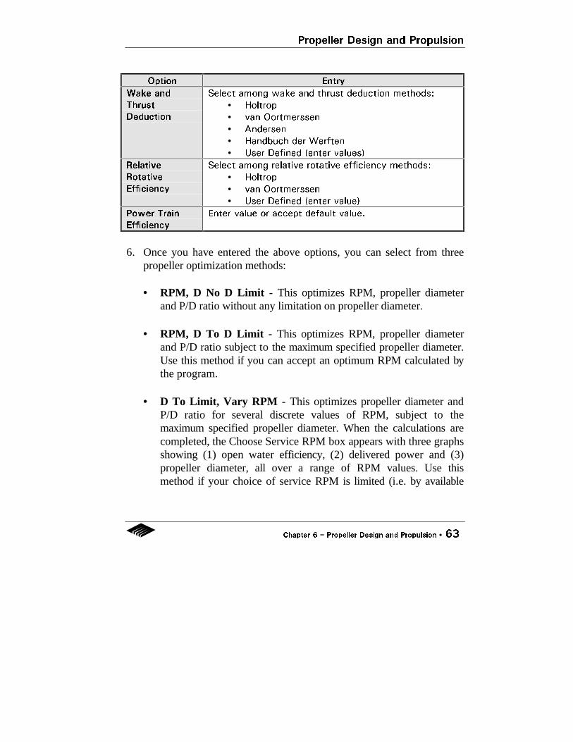
Option Entry
Wake and
Thrust
Deduction
Select among wake and thrust deduction methods:
• Holtrop
• van Oortmerssen
• Andersen
• Handbuch der Werften
• User Defined (enter values)
Relative
Rotative
Efficiency
Select among relative rotative efficiency methods:
• Holtrop
• van Oortmerssen
• User Defined (enter value)
Power Train
Efficiency
Enter value or accept default value.
6. Once you have entered the above options, you can select from threepropeller optimization methods:
• RPM, D No D Limit - This optimizes RPM, propeller diameterand P/D ratio without any limitation on propeller diameter.
• RPM, D To D Limit - This optimizes RPM, propeller diameter
and P/D ratio subject to the maximum specified propeller diameter.Use this method if you can accept an optimum RPM calculated bythe program.
• D To Limit, Vary RPM - This optimizes propeller diameter and
P/D ratio for several discrete values of RPM, subject to themaximum specified propeller diameter. When the calculations arecompleted, the Choose Service RPM box appears with three graphsshowing (1) open water efficiency, (2) delivered power and (3)propeller diameter, all over a range of RPM values. Use thismethod if your choice of service RPM is limited (i.e. by available

Propeller Design and Propulsion
64 •• Chapter 6 −− Propeller Design and Propulsion
gearbox models), then choose the service RPM closest to theoptimum.
Click Close to return to the Propulsion box. 7. The following per propeller optimization results are displayed in the
Results (Per Shaft) frame in the Propulsion box:
• Delivered Power• Shaft Power• RPM• Diameter• P/D (pitch/diameter ratio)• AE/AΟ (expanded area ratio)• Open Water Efficiency

Propeller Design and Propulsion
Chapter 6 −− Propeller Design and Propulsion •• 65
8. Click on the Power Plant button. The Power Plant box appearsdisplaying the following values:
• Shaft Power (power required for the service speed.)• RPM• % MCR (% maximum power)
You can edit these values to represent an available power plant andgear box before making your propulsion calculation.
9. Click OK in the Power Plant box. The Graph display window appearswith three graphs showing (1) resistance versus speed, (2) effectivepower versus speed and (3) thrust and resistance versus speed. ClickOK to close the Graph display window.
10. Click OK to close the Propulsion box. To see the results of yourcalculation, click on the Graph or Table icon.

Propeller Design and Propulsion
66 •• Chapter 6 −− Propeller Design and Propulsion
Notes On Propeller Design and Propulsion
1. Propeller TypeAutopower allows you to choose from among several propeller seriescurrently in use. For further information on the propeller types used inAutopower, we refer you to the following:
• Wageningen B-Series propellers are described briefly in Chapter 7,Algorithms and in detail in The Wageningen Propeller Series,Kuiper, G., MARIN Publication 92-001, 1992 and in Principles ofNaval Architecture Vol. II, Resistance, Propulsion and Vibration,Editor Lewis E.V., Published by SNAME, 1988 (pp. 186-204).
• Ducted Ka propellers with accelerating nozzles and the Kddecelerating nozzle are described in Principles of NavalArchitecture Vol. II, Resistance, Propulsion and Vibration, EditorLewis E.V., Published by SNAME, 1988 (pp. 213-225).
• Gawn-Burrill KCA propeller series is described briefly in Chapter7, Algorithms.
2. AE/AΟΟ (propeller expanded area ratio)For ducted propellers, only the Ka 4-70 (4 blades and .7 area ratio) isprovided. For the Wageningen B and Gawn-Burrill KCA propeller series,you may choose to have Autopower calculate the minimum AE/AΟallowed to limit cavitation, or enter a value of your choice.

Propeller Design and Propulsion
Chapter 6 −− Propeller Design and Propulsion •• 67
3. P/D (pitch / diameter ratio)Autopower optimizes P/D in all calculations subject to the following limits:
Propeller Series Minimum
P/D
Maximum
Fixed P/D
Maximum
Controllable P/D
Wageningen B 0.5 1.4 1.25
Ka Nozzle 0.6 1.8 1.25
Kd Nozzle 1.0 1.8 1.25
Gawn-Burrill KCA 0.8 1.8 1.40
4. Wake and Thrust DeductionYou may enter your estimate of wake factor and thrust deduction factor byselecting the User Defined method. Otherwise, they are calculated by theselected algorithm.
5. RPM, D, No D LimitThis propeller method enables you to calculate the “ideal” propeller for thedesign point speed and thrust (resistance). The resulting propeller isunrestricted in diameter, is subject to P/D ratio limits and is designed toachieve maximum theoretical open water efficiency.
This method may not represent a practical propeller design (i.e. thediameter is often too large). However, it is intended to give the designer atheoretical yardstick against which developed data can be measured. Thismethod enables you to compare calculated optimum efficiency against theefficiency of the propeller optimized to the actual diameter limit.
When the efficiency of the diameter-limited propeller is significantly lowerthan that of the “ideal” propeller, the designer can consider design changesto the hull such as increasing draft. In some instances where calculateddiameter is less than the limit, (e.g. slow, low-power vessels) this methodoffers an instant optimum propeller.
Propeller Design and Propulsion
68 •• Chapter 6 −− Propeller Design and Propulsion
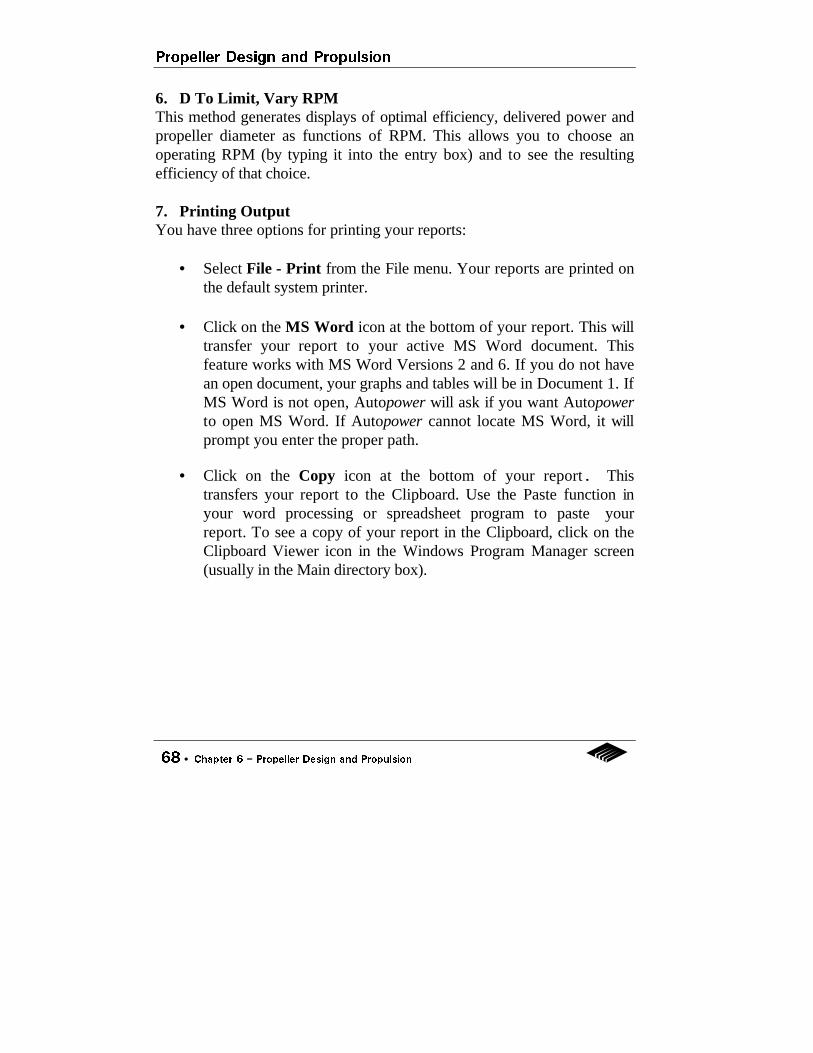
6. D To Limit, Vary RPMThis method generates displays of optimal efficiency, delivered power andpropeller diameter as functions of RPM. This allows you to choose anoperating RPM (by typing it into the entry box) and to see the resultingefficiency of that choice.
7. Printing OutputYou have three options for printing your reports:
• Select File - Print from the File menu. Your reports are printed onthe default system printer.
• Click on the MS Word icon at the bottom of your report. This will
transfer your report to your active MS Word document. Thisfeature works with MS Word Versions 2 and 6. If you do not havean open document, your graphs and tables will be in Document 1. IfMS Word is not open, Autopower will ask if you want Autopowerto open MS Word. If Autopower cannot locate MS Word, it willprompt you enter the proper path.
• Click on the Copy icon at the bottom of your report. Thistransfers your report to the Clipboard. Use the Paste function inyour word processing or spreadsheet program to paste yourreport. To see a copy of your report in the Clipboard, click on theClipboard Viewer icon in the Windows Program Manager screen(usually in the Main directory box).

_________________________________________________________________
Chapter 7 −− Algorithms •• 69
Chapter 7Algorithms
Technical Information on Autopower�s Algorithms
This chapter contains:
• Tables comparing the applicable limits as given by theoriginator of each method.
• Brief descriptions for each method, including background
information and form of regression equations. • Brief descriptions of the propeller series used in Autopower.

Algorithms
70 •• Chapter 7 −− Algorithms
Parameter Symbols
The following symbols are used throughout this chapter:
Parameter SymbolFroude number FnBlock coefficient CbPrismatic coefficient CpMidship section coefficient CmBeam-Draft ratio BTLength-Beam ratio LBLength-Displ ratio LDHalf entrance angle IEVolume Froude number FvTrim angle TRDeadrise angle DRShaft angle EPLength-Beam ratio LB100 (LCG/LBP) LC100 (LCG / Lp) -

Algorithms
_________________________________________________________________
Chapter 7 −− Algorithms •• 71
Applicable Limits -
Displacement
Parameter MethodAndersonMin/Max
FungMin/Max
HoltropMin/Max
OortmersMin/Max
Fn - /0.33 0.18/0.51 - / 1.00 - / 0.50Cb 0.55/0.85 - / - - / - - / -Cp - / - 0.52/0.70 0.55/0.85 0.52/0.70Cm - / - 0.62/0.90 - / - 0.73/0.98BT - / - 2.20/5.20 2.10 / 4.0 1.90/3.40LB 5.00/8.00 - / - 3.90/14.9 3.40/6.20LD 4.00/6.00 5.75/11.3 - / - - / -IE - / - 4.00/16.0 - / - 10.0/38.0
Parameter MethodDigernesMin/Max
Jin/Su/TanMin/Max
CalisalMin/Max
FAOMin/Max
Fn - / 0.50 0.40 / 1.00 - / 0.43 - / 0.36Cb - / - - / - 0.53 / 0.62 - / -Cp - / - 0.57 / 0.76 - / - 0.55 / 0.70Cm - / - - / - - / - 0.53 / 0.93BT - / - - / - 2.00 / 3.00 2.00 / 4.50LB - / - - / - 2.60 / 4.00 3.10 / 5.60LD - / - 4.50 / 8.70 3.00 / 4.50 - / -IE - / - 7.60 / 26.6 - / - 15.0 / 37.0

Algorithms
72 •• Chapter 7 −− Algorithms
Applicable Limits -
Semi-Displacement
Parameter MethodComptonMin/Max
Fn 0.10 / 0.60Fv 0.30 / 1.50TR - / -DR - / -EP - / -LB 4.00 / 5.20
100 (LCG/LBP) 37.0 / 48.0

Algorithms
_________________________________________________________________
Chapter 7 −− Algorithms •• 73
Applicable Limits -
Planing
Parameter MethodSavitskyMin/Max
RadojcicMin/Max
Fn - / - - / -Fv >1.00 1.00 / 3.50TR 3.00 / 7.00 0.00 / 10.00DR 10.0 / 30.00 13.00/ 37.40EP - / - 7.00 /15.00LB 3.00 / 5.00 2.36 / 6.72
100 (LCG / Lp) - / - 30.00/ 44.80

Algorithms
74 •• Chapter 7 −− Algorithms
Applicable Limits -
Catamaran
Parameter MethodFastcat
Min/MaxFn 0.80 / 1.60Cb - / -Cp - / -Cm - / -BT - / -LB - / -LD 5.75 / 7.50IE - / -

Algorithms
_________________________________________________________________
Chapter 7 −− Algorithms •• 75
Andersen and Guldhammer
Limits of Application
Parameter Minimum MaximumFn - 0.33Cb 0.55 0.85Cp - -Cm - -BT - -LB 5.00 8.00LD 4.00 6.00IE - -
Comments
Used for slower displacement hulls.
Background
• Based on The Technical University of Denmark preliminary designprocedure.
• No form factor is used in the formulation.• Contains guidelines for propeller diameter reduction when behind
the hull as functions of the expanded area ratio. This isimplemented in Autopower's third (D To Limit, Vary RPM)propeller optimization option.

Algorithms
76 •• Chapter 7 −− Algorithms
Form of Equation
CT = CR + CF + CA + ∆C
whereCT : residuary resistance coefficientCR : residuary resistance coefficientCF : frictional resistance coefficientCA : incremental resistance coefficient∆C : air and steering resistance coefficient
Selected Reference
• A Computer-Oriented Power Prediction Procedure, Andersen P. andGuldhammer H.E., Proceedings CADMO 86, 1986.

Algorithms
_________________________________________________________________
Chapter 7 −− Algorithms •• 77
Fung
Limits of Application
Parameter Minimum MaximumFn 0.18 0.51Cb - -Cp 0.52 0.70Cm 0.62 0.90BT 2.20 5.20LB - -LD 5.75 11.26IE 4.00 16.00
Comments
Used for transom stern hulls.
Background
• Claimed to cover a broad range of hull forms and Froude numbers.• Data used in the regression analysis include 426 transom stern
ships.• The difference in resistance characteristics between transom and
cruiser stern ships is highlighted in the paper.

Algorithms
78 •• Chapter 7 −− Algorithms
Form of Equation
CR = CR1 + CR2 + CR3 + . . . + CR10
whereCR is the residuary resistance coefficient andCR1 . . . CR10 are tabulated for different hull parameters
over a range of Froude numbers corresponding to 0.18 to 0.51.
Selected Reference
• Resistance and Powering Prediction for Transom Stern Hull FormsDuring Early Stage Ship Design, Fung S.C., SNAME Transactions,Vol. 99, 1991.

Algorithms
_________________________________________________________________
Chapter 7 −− Algorithms •• 79
Holtrop
Limits of Application
Parameter Minimum MaximumFn - 1.00Cb - -Cp 0.55 0.85Cm - -BT 2.10 4.00LB 3.90 14.90LD - -IE - -
Comments
Used for any monohull displacement vessels. Although the maximumFn allowed by the algorithm is 1.00, it is not recommended that Froudenumbers greater than .4 be used.
Background
• Based on regression analysis of full-scale and model test data on334 models at NSMB.
• The 1984 publication also used published Series 64 results.

Algorithms
80 •• Chapter 7 −− Algorithms
Form of Equation
RT = RF (1 + k ) + Rw + RAPP + RA
whereRw : wave resistanceRAPP : appendage resistance (including bulb and transom)RA : correlation allowance
Selected References
• A Statistical Power Prediction Method, Int. Shipbuilding Progress,Holtrop J. and Mennen G.G.J., Vol 25, 1978.
• An Approximate Power Prediction Method, Holtrop J. and MennenG.G.J., Int. Shipbuilding Progress, Vol 29, 1982.
• A Statistical Re-analysis of Resistance and Propulsion Data, HoltropJ., Int. Shipbuilding Progress, Vol 31, 1984.

Algorithms
_________________________________________________________________
Chapter 7 −− Algorithms •• 81
van Oortmerssen
Limits of Application
Parameter Minimum MaximumFn - 0.50Cb - -Cp 0.52 0.70Cm 0.73 0.98BT 1.90 3.40LB 3.40 6.20LD - -IE - -
Comments
Used for small vessels.
Background
• The formulae were obtained using small vessel data (trawlers andtugs) from NSMB.
• Equations were also given for the wake factor, thrust deductionfactor and the relative rotative efficiency.
• Frictional resistance was found using the ITTC 1957 line.

Algorithms
82 •• Chapter 7 −− Algorithms
Form of Equation
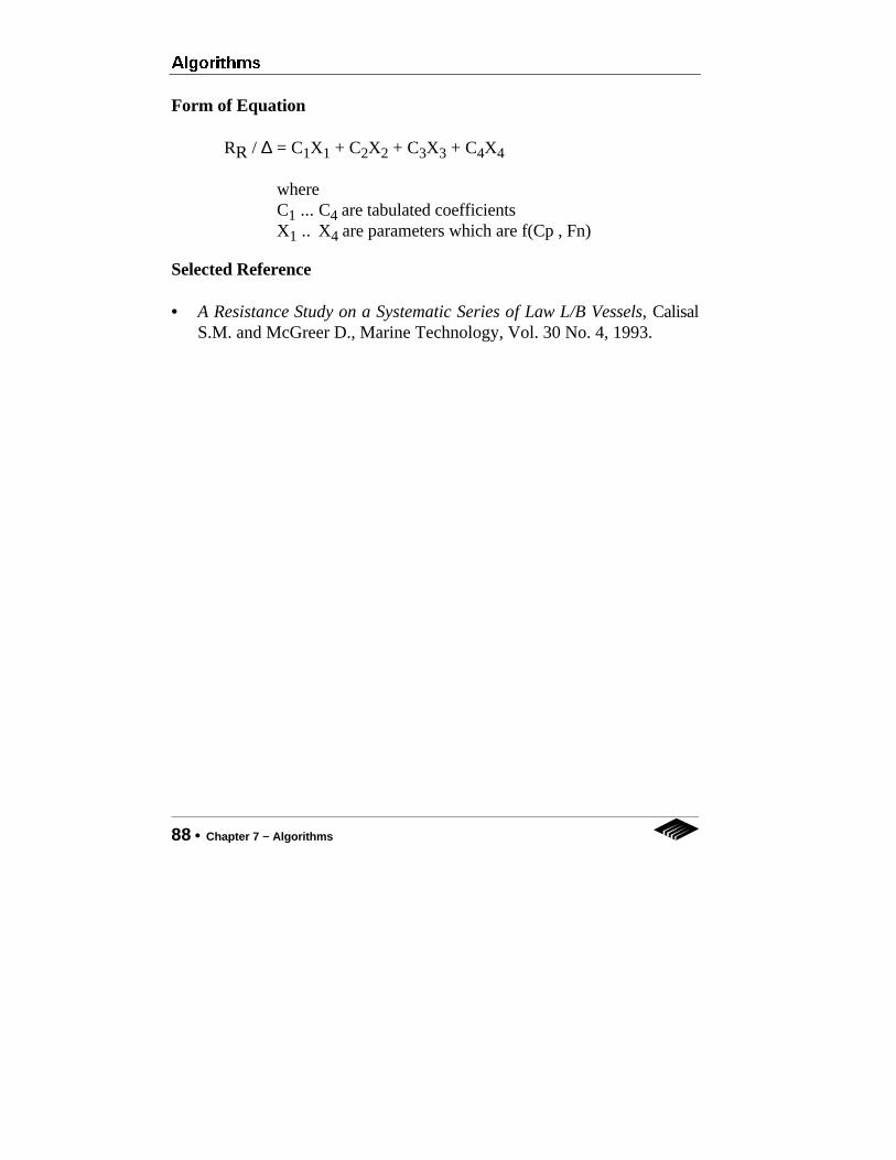
RR / ∆ = C1X1 + C2X2 + C3X3 + C4X4
whereC1 ... C4 are tabulated coefficientsX1 .. X4 are parameters which are f(Cp , Fn)
Selected Reference
• A Power Prediction Method and its Application to Small Ships, Int.Shipbuilding Progress, Vol 18, No.207, 1971.

Algorithms
_________________________________________________________________
Chapter 7 −− Algorithms •• 83
Digernes and Cheng
Limits of Application
Parameter Minimum MaximumFn - 0.50Cb - -Cp - -Cm - -BT - -LB - -LD - -IE - -
Comments
Regression analysis was based on a limited number of fishing vessels.
Background
• Based on regression analysis of 34 Norwegian and 20 Danish ships.• This simple method was compared to several other methods and
found to give good results for fishing vessels.

Algorithms
84 •• Chapter 7 −− Algorithms
Form of Equation
Rt = a (LB)b(BT)c V∂ exp(βFn)
wherea , b, c, ∂, β are constantsV : displacement
Selected Reference
• Utproving av utvalgte formler for beregning av motstand i stille vann,Kjetil Liene, The Norwegian Institute of Fishery Technology ResearchReport (FTFI).

Algorithms
_________________________________________________________________
Chapter 7 −− Algorithms •• 85
Jin, Su and Tan
Limits of Application
Parameter Minimum MaximumFn 0.40 1.00Cb - -Cp 0.57 0.76Cm - -BT - -LB - -LD 4.50 8.70IE 7.60 26.60
Comments
Used for small, round bilge vessels.
Background
• This method is for fast round bilge displacement crafts such asmotor boats and workboats.
• The paper indicated that resistance is affected by the displacementvolume to length ratio, the prismatic coefficient, the transom areato maximum sectional area ratio, the longitudinal center ofbuoyancy, the half entrance angle and the Froude number.

Algorithms
86 •• Chapter 7 −− Algorithms
Form of Equation
CR= B0X0 + B1X1 + ... + B53X53
whereB0 ... B53 are tabulated coefficientsX0 ... X53 are parameters which are functions of geometry
and Fn.
Selected Reference
• A Parametric Study on High-Speed Round Bilge Displacement Hulls,Jin P., Su B. and Tan Z., High-Speed Surface Craft, 1980.

Algorithms
_________________________________________________________________
Chapter 7 −− Algorithms •• 87
Calisal
Limits of Application
Parameter Minimum MaximumFn - 0.42Cb 0.53 0.62Cp - -Cm - -BT 2.00 3.00LB 2.60 4.00LD 3.00 4.50IE - -
Comments
Regression analysis for the University of British Columbia model serieswhich are based on a typical purse seiner.
Background
• Formulae are derived in forms similar to those of Oortmerssen.• Not accurate for Froude number > 0.42.
Algorithms
88 •• Chapter 7 −− Algorithms
Form of Equation
RR / ∆ = C1X1 + C2X2 + C3X3 + C4X4
whereC1 ... C4 are tabulated coefficientsX1 .. X4 are parameters which are f(Cp , Fn)
Selected Reference
• A Resistance Study on a Systematic Series of Law L/B Vessels, CalisalS.M. and McGreer D., Marine Technology, Vol. 30 No. 4, 1993.

Algorithms
_________________________________________________________________
Chapter 7 −− Algorithms •• 89
FAO
Limits of Application
Parameter Minimum MaximumFn - 0.36Cb - -Cp 0.55 0.70Cm 0.53 0.93BT 2.00 4.50LB 3.10 5.60LD - -IE 15.00 37.00
Comments
Used for small fishing vessels.
Background
• Based on Japanese, European and other sources of data, theregression formula was obtained using 570 model test results.

Algorithms
90 •• Chapter 7 −− Algorithms
Form of Equation
CR = CR16 - A (SL/∆) { [ log (B V/(L) .5 ] -2 - [ log (C V(L).5 ] -2}
whereA, B, C are constantsCR16 is the residuary resistance coefficient for a standard 16 ft model
Selected Reference
• Computer-Aided Studies of Fishing Boat Hull Resistance, Hayes J.G.and Engvall L.O., Food and Agriculture Organization of the UnitedNations, FAO Fisheries Technical Paper No. 87 1969.

Algorithms
_________________________________________________________________
Chapter 7 −− Algorithms •• 91
Marintek Fastcat
Limits of Application
Parameter Minimum MaximumFn 0.80 1.60Cb - -Cp - -Cm - -BT - -LB - -LD 5.75 7.50IE - -
Comments
Used for fast catamarans.
Background
• Based on Marintek (Norway) tests on high speed slendercatamarans.
• Model to full scale correlation for high speed catamarans has beendeveloped based on extensive full scale experiments.
• Propulsion efficiencies are given as options in the program.• The frictional coefficient is found using the ITTC 1957 line.

Algorithms
92 •• Chapter 7 −− Algorithms
Form of Equation
RT = A ( CF + CR + ∆CF ) V2 S + RAA
whereA : constant∆CF : roughness allowance (0.0005 corresponds to hull
roughness of approximately 150 µm)RAA : air resistance allowanceS : total wetted hull surface areaV : velocity
Selected Reference
• Design Tool for High Speed Slender Catamarans, Werenskold,Published letter from Marintek, Ocean Laboratories in Trondheim,Norway.

Algorithms
_________________________________________________________________
Chapter 7 −− Algorithms •• 93
Compton
Limits of Application
Parameter Minimum MaximumFn 0.10 0.60Fv 0.30 1.50TR - -DR - -EP - -LB 4.00 5.20
100 (LCG/LBP) 37.00 48.00
Comments
US Naval Academy YP Series.
Background
• Based on experimental investigations of a systematic series of smallsemi-displacement models.
• Both soft and hard chine crafts are accommodated.

Algorithms
94 •• Chapter 7 −− Algorithms
Form of Equation
CR * 103 = A + B (LB) + C (∆) + D (100 [LCG/LBP] )whereA, B, C, D : tabulated coefficients∆ : displacement based on LBP
Selected Reference
• Resistance of a Systematic Series of Semi-Planing Transom-SternHulls, Compton R.H., Marine Technology, Vol 23 No. 4, 1986.

Algorithms
_________________________________________________________________
Chapter 7 −− Algorithms •• 95
Savitsky
Limits of Application
Parameter Minimum MaximumFn 0.60 1.79Fv >1.00 -TR 3.00 7.00DR 10.00 30.00EP - -LB 3.00 5.00
100 (LCG/Lp) - -
Comments
Constant deadrise.
Background
• Resistance and trim are calculated in the preplaning (where 1.00 <Fv < 2.00 ) and planing (Fv ≥ 2.00) regimes for prismatic planinghulls.
• The user can also use the Blount multiplier, a correction ratio tocompensate for hump-speed resistance under-prediction using thepure Savitsky method.
• Wave added resistance is not considered in this program.

Algorithms
96 •• Chapter 7 −− Algorithms
Form of Equation
Preplaning Regime : RT/∆ = A1F1 + ... A27F27
whereA1 ... A27 : tabulated coefficientsF1 ... F27 : f(entrance angle, max chine beam, ∇)
Planing Regime : RT = ∆ tan(TR) + F(hull parameters,TR,Speed)
Selected References
• Hydrodynamic Design of Planing Hulls, Savitsky D., MarineTechnology, Vol. 1 No. 1, 1964.
• Small-craft Power Prediction, Blount D.L. and Fox D.L., MarineTechnology, Vol. 13 No. 1, 1976.
• Procedures for Hydrodynamic Evaluation of Planing Hulls in Smoothand Rough Water, Savitsky D. and Brown W., Marine Technology,Vol. 13 No. 4, 1976.

Algorithms
_________________________________________________________________
Chapter 7 −− Algorithms •• 97
Radojcic
Limits of Application
Parameter Minimum MaximumFn - -Fv 1.00 3.50TR 0.00 10.00DR 13.00 37.40EP 7.00 15.00LB 2.36 6.72
100 (LCG/Lp) 30.00 44.80
Comments
Used for hard-chined planing hulls.
Background
• Based on Series 65-B, TMB-62 and DL-62-A hulls.• Transom flap effects are based on Savitsky and Brown (see
Savitsky algorithm).

Algorithms
98 •• Chapter 7 −− Algorithms
Form of Equation
R/∆ = A0X0 + ... A26X26
TR = B0X0 + ... B26X26
whereA0 ... A26 : tabulated coefficientsB0 ... B26 : tabulated coefficientsX0 ... X26 : f(hull parameters)
Selected Reference
• An Engineering Approach to Predicting the HydrodynamicPerformance of Planing Craft Using Computer Techniques, RadojcicD., Trans RINA, 1991.

Algorithms
_________________________________________________________________
Chapter 7 −− Algorithms •• 99
B-Series Propellers (MARIN)
The B-series of propellers are among the most popular to date. Thrust andtorque coefficients are represented by polynomials (see reference) in termsof the following propeller parameters: advance ratio J, pitch ratio P/D,expanded area ratio AE/A0 and number of blades Z.
KT = f ( J , P/D , AE/A0 , Z )KQ = f ( J , P/D , AE/A0 , Z )
The following parameter ranges are applicable:
• P/D : 0.50 - 1.40• AE/A0 : 0.30 - 1.05• Z : 3 - 7
A Reynolds number correction is required for Rn > 2 x 10⁶.
The propeller open water efficiency is given by:
η0 = J/2π KT / KQ
Except where the user chooses a value, the optimization algorithm sets theexpanded area ratio to the smallest value consistent with the chosen backcavitation limit. An initial estimate is obtained from Keller’s formula andthis is refined in each solution iteration by applying Burrill’s formula. Thenumber of blades is normally dictated by vibration considerations. Propellerdiameter is limited by considerations of hull clearance and adequateimmersion in the ballast condition. Propeller RPM should be chosen withregard to engine and transmission gear limitations. Depending on theoptimization mode chosen, a range of pitch ratios and RPMs/propellerdiameters are used to determine the optimum open water efficiency.

Algorithms
100 •• Chapter 7 −− Algorithms
Selected Reference
• Principles of Naval Architecture Vol II, Resistance, Propulsion andVibration, Editor Lewis E.V., Published by SNAME, 1988.

Algorithms
_________________________________________________________________
Chapter 7 −− Algorithms •• 101
Gawn-Burrill KCA Series
Thrust and torque coefficients are represented by polynomials (seereference below) in terms of the following propeller parameters: advanceratio J, pitch ratio P/D, expanded area ratio AD/A0. The polynomials aregiven for 3-bladed propellers only.
KT = f ( J , P/D , AD/A0 )KQ = f ( J , P/D , AD/A0 )
The following parameter ranges are applicable:
• P/D : 0.80 - 1.80• AD/A0 : 0.50 - 1.10• Z : 3• J : ≥ 0.3
The minimum back cavitation design criterion results in the requireddeveloped area ratio to be:
AD/A0 = A KT f ( w , σ0 , J , P/D )
where A : constant depending on the degree of allowed back cavitation.
w : wake factor σ0 : cavitation number based on advance velocity
Propeller diameter is limited by considerations of hull clearance. PropellerRPM should be chosen with regard to engine and transmission gearlimitations. Depending on the optimization mode chosen, a range of pitchratios and RPMs/propeller diameters are used to determine the optimumopen water efficiency.

Algorithms
102 •• Chapter 7 −− Algorithms
Selected Reference
• An Engineering Approach to Predicting the HydrodynamicPerformance of Planing Craft Using Computer Techniques, RadojcicD., Trans RINA, 1991.
Algorithms
_________________________________________________________________
Chapter 7 −− Algorithms •• 103
Ducted Propellers (MARIN)
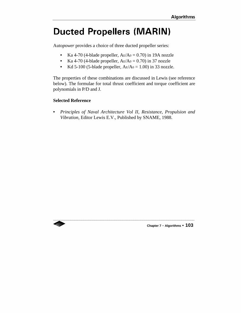
Autopower provides a choice of three ducted propeller series:
• Ka 4-70 (4-blade propeller, AE/A0 = 0.70) in 19A nozzle• Ka 4-70 (4-blade propeller, AE/A0 = 0.70) in 37 nozzle• Kd 5-100 (5-blade propeller, AE/A0 = 1.00) in 33 nozzle.
The properties of these combinations are discussed in Lewis (see referencebelow). The formulae for total thrust coefficient and torque coefficient arepolynomials in P/D and J.
Selected Reference
• Principles of Naval Architecture Vol II, Resistance, Propulsion andVibration, Editor Lewis E.V., Published by SNAME, 1988.

Algorithms
104 •• Chapter 7 −− Algorithms

Index
Index •• 105
INDEX
—A—AE/AO, 62, 66Algorithms, 69-103Andersen, 75-76Angle at 1/4 buttock, 43Appendage form factor, 43, 46Appendage margin, 43, 45applicable limits, 71-74Autobuild, 4autoexec.bat file, 7Autohydro, 4Autoload, 4Autopower, 1Autoship, 4
—B—Blades, 62Block coefficient, 43Blount Multiplier, 54Body Type - (A), 43Body Type - (F), 43Breadth, 42, 44Browse Methods, 50, 57B-Series propellers, 66, 99-100Bulb Centroid Location, 43Bulbous Bow, 43
—C—Calculate button, 54Calculating Resistance, 49-58Calisal, 87-88catamaran propulsion, 59
CB, 43Chine Beam, 44Chine length, 44Chine Type, 54Choose Service RPM box, 64Clear Grid, 30CM, 42Compton, 93-94Copy Cell, 28Copy Column, 29Copy icon, 58CP, 43CPU, 6CWP, 42CX, 44
—D—Deadrise angle, 44default settings, 18Demo version, 2, 8, 11-12Design Point, 62Digernes, 83-84disk space, 6Displacement, 42, 44Draft, 44Draft (A), 42Draft (F), 42Draft aft, 42Draft forward, 42draft value, 48ducted propellers, 66, 103

Index
106 •• Index
—E—Edit-Clear Grid, 30Edit-Copy Cell, 28Edit-Copy Column, 29Edit-Paste Cell, 28Edit-Paste Column, 29entering, 14exiting, 14expanded area ratio, 62, 66
—F—FAO, 43, 89-90Fastcat, 91-92File-Exit, 27File-Open, 22File-Page Setup, 25File-Print, 26File-Save, 23, 47File-Save As, 24Flap chord length, 45Flap deflection angle, 45Flap span to beam ratio, 45Fonts, 11, 25Form factor, 42, 53fresh water, 35Full version, 2Fung, 77-78
—G—Gawn-Burrill KCA Series, 101-102Graph icon, 54graphics, 6
—H—Half angle of entrance, 42, 44
Half angle of run, 43Help menu, 37-40Help-About Autopower, 40Help-Contents, 38Help-Using Help, 39Holtrop, 46, 79-80hull parameters, 41-48Hull Parameter Grids, 41-45Hull-Wetted Area, 53
—I—importing parameters, 48information box, 41installation, 7-12
—J—Jin, 85-86
—K—keyboard, 15
—L—LCB, 42LCG, 44Length on design waterline, 42limit diameter, 62limits for methods, 71-98Longitudinal center of bouyancy, 42Longitudinal center of gravity, 44LWL, 42, 44
—M—main screen, 16Marintek Fastcat, 91-92Maximum section coefficient, 44MCR, 65

Index
Index •• 107
memory, 6menu system, 17, 21-40Midship section area coefficient, 42mouse, 15MS Word icon, 57
—O—Oortmerssen, 81-82operating system, 6
—P—package contents, 2Page Setup, 25parameter grids, hull, 42-45parameter symbols, 57, 70Paste Column, 29Paste-Cell, 28pitch/diameter ratio, 67power method, 60Power Plant DB, 65Power train efficiency, 63Print, 26Printing output, 57, 58, 68Prismatic coefficient, 43Project Name, 42, 44projected area of inlets, 45Projected area of skeg, 45propeller design, 59-68propeller optimization, 60, 63, 67, 68propeller optimization methods, 63-64propeller pitch, 62propeller type, 62, 66propulsion, 59-68Propulsion DB, 61propulsion icon, 59Propulsive Coefficient, 54
—R—Radojcic, 97-98relative rotative efficiency, 63Reports, 34, 55-58Resistance Allowances, 54resistance methods, 19, 69-98Resistance Options, 51-54RPM, 63, 65, 67, 68Rudder Surface Area, 45Rudder Type, 45, 47
—S—Save As, 24Savitsky, 44, 95-96Sea Inlets, 45sea water, 35sea water inlets, 45Service margin, 43, 45Settings-Fresh Water, 35Settings-Imperial, 36Settings-Metric, 36Settings-Sea Water, 35Shaft Angle, 44Shaft Diameter, 44Shaft Length, 44Solve-Calculate Now, 33Solve-Propulsion, 32Solve-Reports, 34Solve-Resistance, 31Speeds button, 50-51Strut Type, 44system requirements, 6
—T—Table icon, 54thrust and resistance graph, 65Transom width, 42
Index
108 •• Index
Transverse bulb area, 43Type, propeller, 62
—U—units, 36upgrading, 11-12Using Help, 39
—V—van Oortmerssen, 81-82Vary RPM, 63, 68, 75versions, 2
—W—Wageningen, 66, 99-100Wake and thrust deduction, 63, 67Waterplane area coefficient, 42Wetted appendage area, 42Wetted hull area, 42, 44Wetted transom area, 42, 44


AUTOPOWER UPGRADE ORDER FORM
Autoship Systems Corporation Tel (604) 254-4171 Fax (604) 254-5171
Please process my upgrade from Demo to Full Version
PRODUCT REGISTRATION INFORMATION
Date
Serial #
Name
Company
Address
Tel Fax
PRICE ($ US) PAYMENT
$ Regular Price qq Cheque qq Wire Transfer
$ Less Demo Price qq Visa qq MC qq AMEX
$ Delivery Charges Card #
$ Taxes Expiry Date
$ TOTAL Signature
• • Delivery Charges: $20 Airmail, $50 Courier
• • Taxes: Canadian Residents add GST & PST where applicable
• • Wire Transfer: to $US account # 7600 - 001 - 4605 - 597 with Bank
• • of Montreal, 2601 Granville Street, Vancouver, BC V6J 4M7 Canada
(ASC Use Only) UPGRADE CONFIRMATION Access Code