Embed Size (px)
Citation preview
QUICK START INSTRUCTIONS WAPC250
For parts, product & service informationvisit www.waynepumps.com
Auto On-Off Water Removal Pool Cover PumpOPERATING INSTRUCTIONS & PARTS MANUAL
READ, UNDERSTAND AND FOLLOW ALL INSTRUCTIONS IN THIS MANUAL - DO NOT DISCARD. Failure to follow these instructions could result in property damage, serious injury or death.
© 2012, WAYNE/Scott Fetzer Company.
323900-001 4/12
(1) POOL COVER PUMP
(1) PUMP STRAINER
STEP 1 - VERIFY PACKAGE CONTENTS
STEP 2 - INSTALL CHECK VALVE
STEP 3 - ATTACH STRAINER
STEP 4 - CONNECT GARDEN HOSE
STEP 5 - SECURE ROPE TO STRAINER
STEP 6 - POSITION ON POOL COVER
STEP 7 - PLUG INTO GFCI OUTLET
FOR FURTHER PLACEMENT TECHNIQUES AND DETAILED INSTALLATION FOR INGROUND AND ABOVE GROUND POOL APPLICATIONS, REFER TO PAGE 3 - FIGURES (A-E).
(1) CHECK VALVE/HOSE ADAPTER
(1) 25' ROPE
ROTATE PUMP DOWN TO LOCK
LISTEN FOR PUMP TO "CLICK" IN PLACE
FEED ROPE THROUGH LOOP ON STRAINER AND SECURE WITH KNOT
CLICK
TOP
INSTALL CHECK VALVE SO ARROWS ARE POINTING UPWARD
WAPC250
For parts, product & service information visit www.waynepumps.com
REMINDER: Keep your dated proof of purchase for warranty purposes! Attach it to this manual or file it for safekeeping.
Auto On-Off Water Removal Pool Cover PumpOPERATING INSTRUCTIONS & PARTS MANUAL
READ, UNDERSTAND AND FOLLOW ALL INSTRUCTIONS IN THIS MANUAL - DO NOT DISCARD. Failure to follow these instructions could result in property damage, serious injury or death.
Risk of electric shock. This pump has NOT been tested for use in marine
areas. NEVER place pump in pools while people are in the water. Do NOT handle pump with wet hands or when standing in water or on a damp surface. Pump is designed to be used in closed and covered pools only. Water accumulated on pool cover can cause injury or death. Proper installation of pool cover pump and periodic maintenance is recommended. Failure to follow COULD result in death or serious injury.
1. Wear safety glasses at all times when working
with pumps.
2. The unit MUST be plugged into a properly grounded GFCI outlet. Consult with a qualified electrician for proper installation of a GFCI OUTLET.
3. DO NOT MOVE, POSITION, RETRIEVE, OR CARRY PUMP USING THE POWER CORD OR THE DISHCHARGE HOSE, damage to the pump or power cord may occur. Use the handle supplied on the pump or attach a string to the strainer to position as instructed.
APPLICATION AND OPERATION Do NOT use pump if any part of the housing
switch or probe is cracked, broken, or missing.
Always disconnect electric supply
before attempting to install, service, relocate, or perform any maintenance. If the power source is out of sight, lock and tag in open (off) position to prevent unexpected power application. Failure to do so WILL result in fatal electrical shock!
Electric shock hazard. Use only Underwriters Laboratories
(UL)- listed extension cord with #16 gauge or larger wire that is labeled for outdoor use. Use polarized grounding type plugs only. Polarized plugs have one blade slightly wider than the other and can only be inserted one way into the outlet. If using an extension cord, do NOT allow pump cord/extension cord connection to fall into swimming pool or come in contact with water. Pump/extension cord connection must be kept dry and away from moisture. Do NOT handle plug connector near water. Failure to follow these instructions WILL result in death or serious injury.
This unit is NOT designed for use as a sump pump or in sump
applications. This unit is NOT designed for use in septic tanks or underground vaults to pump raw sewage or effluents. NEVER use in hazardous or explosive locations.
DESCRIPTIONThis portable, Auto On-Off Pool Cover pump is designed for automatic removal of water, from a pool or spa cover. The units are equipped with a 25 ft. 3-prong grounding type power cord. The provided discharge check valve prevents short cycling and it's 3/4 in adapter can be used for convenient attachment to a standard garden hose.
UNPACKINGInspect this unit before it is used. Occasionally, products are damaged during shipment. If the pump or components are damaged, contact customer service at 1-800-237-0987.
SAFETY GUIDELINESTo help recognize this information, observe the following signal words/hazard classifications. This is the safety alert symbol. It is used to alert you to potential bodily injury hazards. Obey all safety messages that follow this symbol to avoid possible harm.
Danger indicates an imminently hazardous situation which, if NOT avoided, WILL result
in death or serious injury.
Warning indicates a potentially hazardous situation which, if NOT avoided, COULD
result in death or serious injury.
Caution indicates a potentially hazardous situation which, if NOT avoided, MAY result
in minor or moderate injury.
Notice indicates important information, that if NOT followed, MAY cause damage to equipment.
NOTE: Note indicates information that requires special attention.
GENERAL SAFETY INFORMATIONGENERAL SAFETY• Readthemanual(s)includedwiththisproduct
carefully. Be thoroughly familiar with the controls and the proper use of the equipment. Follow all instructions.
• Onlypersonswellacquaintedwiththeserulesofsafeoperation should be allowed to use the unit. Keep away
from children!
This pump is NOT rated for use with flammable/combustible liquids vapors or dusts. Do NOT use to pump flammable/combustible liquids vapors or dusts. Do NOT use in a flammable and/or explosive atmosphere. Pump SHOULD be used to pump clear water ONLY. Failure to follow these instructions WILL result in bodily injury or death.
Electric shock hazard! GFCI receptacles will provide protection
against line to ground faults only. The ground fault receptacle does NOT limit the magnitude of fault current and will NOT prevent an electrical shock. Replace damaged cord immediately.
© 2012, WAYNE/Scott Fetzer Company.
Do NOT disassemble or alter this product in any way. Failure to
follow these instructions WILL result in serious injury or death.
2
3
www.waynepumps.com
POOL COVER
APPLICATION AND OPERATION (CON'T)
1. This pump has been designed with 1-1/4 in. NPT discharge connection size. Attach pipe or fitting to the discharge or use the supplied garden hose adapter/check valve. Thread the female end of the garden hose to the male end of the garden hose adapter/check valve.
2. Use a hose washer (not included) on the garden hose for correct pump operation.
3. For best pump performance, unwind the hose before starting the pump. This will help remove any kinks or binds in the hose and allow the unit to pump with less restriction.
a. DO NOT place the pump on a weak, damaged, or leaking pool cover. Placing the pump on a damaged pool cover could cause the cover to give way, or could allow the pump to remove treated swimming water from the pool in addition to rainwater.
b. Install the “snap-on” debris strainer. Begin by lining up the pump base profile with the profile of the strainer base using the switch housing as a guide. Tilt the pump back and guide the rear of the pump (opposite the discharge) into the strainer base. Once the rear of the pump is in place, gently rotate the pump down until the latch engages.
c. To remove debris strainer release latch and guide pump out of strainer in the reverse motion of installation.
4. With pump unplugged set the pump on the pool cover, where water will collect. Do NOT set the pump directly on mud, sand surfaces or in leaves. For best results make sure the pump strainer is making full contact with a clean area of the pool cover. This will allow the strainer to properly filter debris and help prevent clogging of the pump. If necessary clear an area of the pool cover before placing the pump. For further placement techniques see (Figures A-E).
PULL ACROSS PUMP INSTALLATION To aid in pump placement on pool cover, secure provided 25
ft. rope to the pull to shore loop (Figure B).
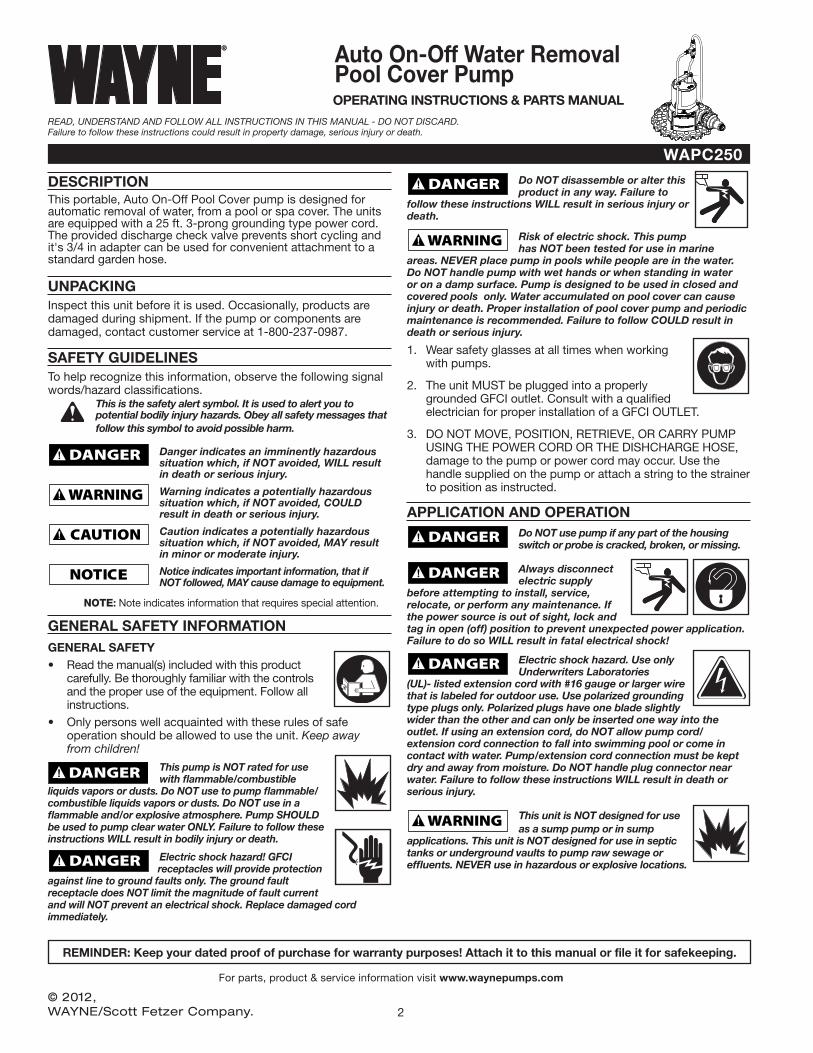
Figure A - In-ground pool installation (cut-away view)
A2A3
15' MAXIMUM PUMPING HEIGHT
DISCHARGE HOSE
AVOID PINCHING OR DAMAGING POWER CORD AND HOSE ON POOL EDGE
A1
A1. Connect discharge hose to pump check valve and place hose end away from pool, where water will be displaced.
A2. Attach provided 25 ft. rope to handle of pump, and lower pump onto pool cover where water will collect.
A3. Do NOT exceed the 15 ft. maximum pumping height for this pump or switch may not function properly. Plug in pump to allow for automatic operation.
For REMOVAL unplug pump and retrieve using rope.
Figure B - Pull to shore loop
FEED ROPE THROUGH LOOP AND SECURE WITH KNOT
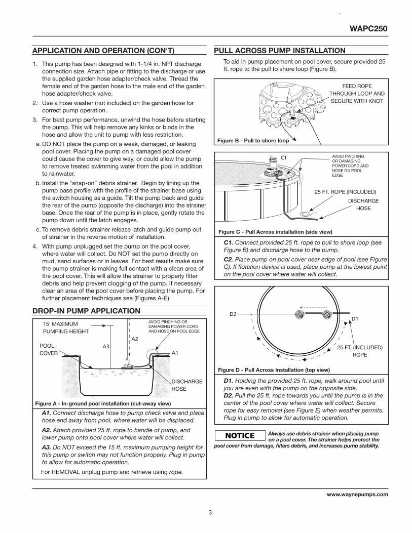
D1. Holding the provided 25 ft. rope, walk around pool until you are even with the pump on the opposite side. D2. Pull the 25 ft. rope towards you until the pump is in the center of the pool cover where water will collect. Secure rope for easy removal (see Figure E) when weather permits. Plug in pump to allow for automatic operation.
Figure C - Pull Across installation (side view)
C1
25 FT. ROPE (INCLUDED)
DISCHARGE HOSE
AVOID PINCHING OR DAMAGING POWER CORD AND HOSE ON POOL EDGE
C1. Connect provided 25 ft. rope to pull to shore loop (see Figure B) and discharge hose to the pump.
C2. Place pump on pool cover near edge of pool (see Figure C). If flotation device is used, place pump at the lowest point on the pool cover where water will collect.
Figure D - Pull Across Installation (top view)
D2D1
25 FT. (INCLUDED) ROPE
DROP-IN PUMP APPLICATION
Always use debris strainer when placing pump on a pool cover. The strainer helps protect the
pool cover from damage, filters debris, and increases pump stability.
WAPC250
4
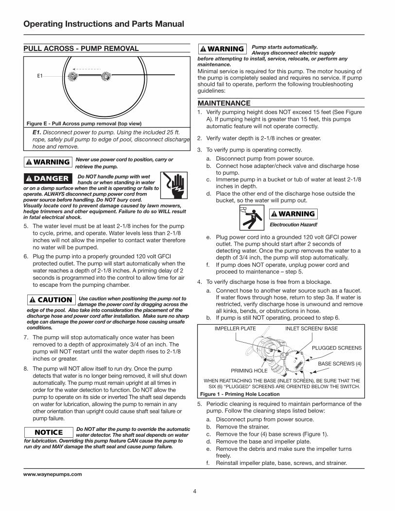
PULL ACROSS - PUMP REMOVAL
Figure E - Pull Across pump removal (top view)
E1
E1. Disconnect power to pump. Using the included 25 ft. rope, safely pull pump to edge of pool, disconnect discharge hose and remove.
Never use power cord to position, carry or
retrieve the pump.
will be pumped. Do NOT handle pump with wet hands or when standing in water
or on a damp surface when the unit is operating or fails to operate. ALWAYS disconnect pump power cord from power source before handling. Do NOT bury cord. Visually locate cord to prevent damage caused by lawn mowers, hedge trimmers and other equipment. Failure to do so WILL result in fatal electrical shock.
Do NOT alter the pump to override the automatic water detector. The shaft seal depends on water
for lubrication. Overriding this pump feature CAN cause the pump to run dry and MAY damage the shaft seal and cause pump failure.
5. The water level must be at least 2-1/8 inches for the pump to cycle, prime, and operate. Water levels less than 2-1/8 inches will not allow the impeller to contact water therefore no water will be pumped.
6. Plug the pump into a properly grounded 120 volt GFCI protected outlet. The pump will start automatically when the water reaches a depth of 2-1/8 inches. A priming delay of 2 seconds is programmed into the control to allow time for air to escape from the pumping chamber.
Use caution when positioning the pump not to damage the power cord by dragging across the
edge of the pool. Also take into consideration the placement of the discharge hose and power cord after installation. Make sure no sharp edge can damage the power cord or discharge hose causing unsafe conditions.
7. The pump will stop automatically once water has been removed to a depth of approximately 3/4 of an inch. The pump will NOT restart until the water depth rises to 2-1/8 inches or greater.
8. The pump will NOT allow itself to run dry. Once the pump detects that water is no longer being removed, it will shut down automatically. The pump must remain upright at all times in order for the water detection to function. Do NOT allow the pump to operate on its side or inverted The shaft seal depends on water for lubrication, allowing the pump to remain in any other orientation than upright could cause shaft seal failure or pump failure.
Pump starts automatically. Always disconnect electric supply
before attempting to install, service, relocate, or perform any maintenance.Minimal service is required for this pump. The motor housing of the pump is completely sealed and requires no service. If pump should fail to operate, perform the following troubleshooting guidelines:
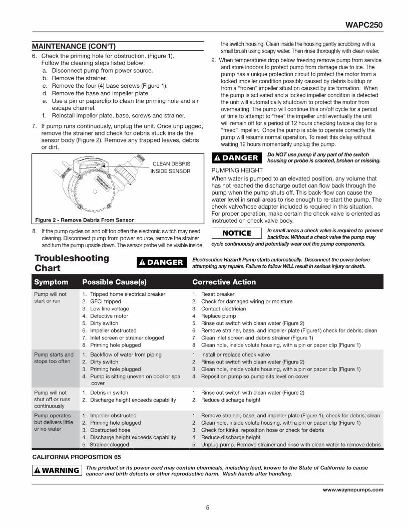
PRIMING HOLE BASE SCREWS (4)
INLET SCREEN/ BASEIMPELLER PLATE
Figure 1 - Priming Hole Location
WHEN REATTACHING THE BASE (INLET SCREEN), BE SURE THAT THE SIX (6) "PLUGGED" SCREENS ARE ORIENTED BELOW THE SWITCH.
5. Periodic cleaning is required to maintain performance of the pump. Follow the cleaning steps listed below:
a. Disconnect pump from power source.b. Remove the strainer.c. Remove the four (4) base screws (Figure 1).d. Remove the base and impeller plate.e. Remove the debris and make sure the impeller turns
freely.f. Reinstall impeller plate, base, screws, and strainer.
1. Verify pumping height does NOT exceed 15 feet (See Figure A). If pumping height is greater than 15 feet, this pumps automatic feature will not operate correctly.
2. Verify water depth is 2-1/8 inches or greater.
3. To verify pump is operating correctly.
a. Disconnect pump from power source.b. Connect hose adapter/check valve and discharge hose
to pump.c. Immerse pump in a bucket or tub of water at least 2-1/8
inches in depth.d. Place the other end of the discharge hose outside the
bucket, so the water will pump out.
e. Plug power cord into a grounded 120 volt GFCI power outlet. The pump should start after 2 seconds of detecting water. Once the pump removes the water to a depth of 3/4 inch, the pump will stop automatically.
f. If pump does NOT operate, unplug power cord and proceed to maintenance – step 5.
4. To verify discharge hose is free from a blockage.
a. Connect hose to another water source such as a faucet. If water flows through hose, return to step 3a. If water is restricted, verify discharge hose is unwound and remove all kinks, bends, or obstructions in hose.
b. If pump is still NOT operating, proceed to step 6.
MAINTENANCE
Electrocution Hazard!
PLUGGED SCREENS
Operating Instructions and Parts Manual
www.waynepumps.com
5
6. Check the priming hole for obstruction. (Figure 1). Follow the cleaning steps listed below:a. Disconnect pump from power source.b. Remove the strainer.c. Remove the four (4) base screws (Figure 1).d. Remove the base and impeller plate.e. Use a pin or paperclip to clean the priming hole and air
escape channel.f. Reinstall impeller plate, base, screws and strainer.
7. If pump runs continuously, unplug the unit. Once unplugged, remove the strainer and check for debris stuck inside the sensor body (Figure 2). Remove any trapped leaves, debris or dirt.
Figure 2 - Remove Debris From Sensor
CLEAN DEBRIS INSIDE SENSOR
8. If the pump cycles on and off too often the electronic switch may need cleaning. Disconnect pump from power source, remove the strainer and turn the pump upside down. The sensor probe will be visible inside
Do NOT use pump if any part of the switch housing or probe is cracked, broken or missing.
PUMPING HEIGHTWhen water is pumped to an elevated position, any volume that has not reached the discharge outlet can flow back through the pump when the pump shuts off. This back-flow can cause the water level in small areas to rise enough to re-start the pump. The check valve/hose adapter included is required in this situation. For proper operation, make certain the check valve is oriented as instructed on check valve body.
In small areas a check valve is required to prevent backflow. Without a check valve the pump may
cycle continuously and potentially wear out the pump components.
the switch housing. Clean inside the housing gently scrubbing with a small brush using soapy water. Then rinse thoroughly with clean water.
9. When temperatures drop below freezing remove pump from service and store indoors to protect pump from damage due to ice. The pump has a unique protection circuit to protect the motor from a locked impeller condition possibly caused by debris buildup or from a “frozen” impeller situation caused by ice formation. When the pump is activated and a locked impeller condition is detected the unit will automatically shutdown to protect the motor from overheating. The pump will continue this on/off cycle for a period of time to attempt to “free” the impeller until eventually the unit will remain off for a period of 12 hours checking twice a day for a “freed” impeller. Once the pump is able to operate correctly the pump will resume normal operation. To reset this delay without waiting 12 hours momentarily unplug the pump.
Troubleshooting Chart
Electrocution Hazard! Pump starts automatically. Disconnect the power before attempting any repairs. Failure to follow WILL result in serious injury or death.
Symptom Possible Cause(s) Corrective Action
Pump will not start or run
1. Tripped home electrical breaker2. GFCI tripped3. Low line voltage4. Defective motor5. Dirty switch6. Impeller obstructed7. Inlet screen or strainer clogged8. Priming hole plugged
1. Reset breaker2. Check for damaged wiring or moisture3. Contact electrician4. Replace pump5. Rinse out switch with clean water (Figure 2)6. Remove strainer, base, and impeller plate (Figure1) check for debris; clean7. Clean inlet screen and debris strainer (Figure 1) 8. Clean hole, inside volute housing, with a pin or paper clip (Figure 1)
Pump starts and stops too often
1. Backflow of water from piping2. Dirty switch3. Priming hole plugged4. Pump is sitting uneven on pool or spa
cover
1. Install or replace check valve 2. Rinse out switch with clean water (Figure 2)3. Clean hole, inside volute housing, with a pin or paper clip (Figure 1)4. Reposition pump so pump sits level on cover
Pump will not shut off or runs continuously
1. Debris in switch2. Discharge height exceeds capability
1. Rinse out switch with clean water (Figure 2)2. Reduce discharge height
Pump operates but delivers little or no water
1. Impeller obstructed2. Priming hole plugged3. Obstructed hose4. Discharge height exceeds capability5. Strainer clogged
1. Remove strainer, base, and impeller plate (Figure 1), check for debris; clean2. Clean hole, inside volute housing, with a pin or paper clip (Figure 1)3. Check for kinks, reposition hose or check for debris4. Reduce discharge height5. Unplug pump. Remove strainer and rinse with clean water to remove debris
MAINTENANCE (CON'T)
This product or its power cord may contain chemicals, including lead, known to the State of California to cause cancer and birth defects or other reproductive harm. Wash hands after handling.
CALIFORNIA PROPOSITION 65
WAPC250
www.waynepumps.com
Limited WarrantyFor three years from the date of purchase, WAYNE Water Systems Division ("WAYNE Pumps") will repair or re place, at its option, for the original purchaser any part or parts of its Water Pumps (“Product”) found upon examination by WAYNE to be defective in materials or work man ship. Please call WAYNE Pumps (1-800-237-0987) for instructions. Be pre pared to provide the model number and the serial number when exercising this warranty. All transportation charges on Products or parts submitted for repair or replacement must be paid by purchaser.
This Limited Warranty does not cover Products which have been damaged as a result of accident, abuse, misuse, neglect, improper application, improper maintenance, or failure to operate in accordance with WAYNE Pumps' written instructions.
THERE IS NO OTHER EXPRESS WARRANTY. IMPLIED WARRANTIES, IN CLUD ING THOSE OF MER CHANTABIL I TY AND FITNESS FOR A PARTICULAR PUR POSE, ARE LIMITED TO ONE YEAR FROM THE DATE OF PURCHASE. THIS IS THE EXCLUSIVE REM E DY AND ANY LIABILITY FOR ANY AND ALL INDIRECT OR CONSEQUENTIAL DAM AG ES OR EXPENSES WHATSOEVER IS EXCLUDED.
Some states do not allow limitations on how long an implied warranty lasts, or do not allow the exclusions or limitations of incidental or consequential damages, so the above lim i ta tions might not apply to you. This limited war ran ty gives you specific legal rights, and you may also have other legal rights which vary from state to state.
In no event, whether as a result of breach of contract warranty, tort (in clud ing negligence) or otherwise, shall WAYNE Pumps or its suppliers be liable for any special, consequential, incidental or penal damages including, but not limited to loss of profit or revenues, loss of use of the products or any associated equipment, damage to associated equip ment, cost of capital, cost of substitute products, facilities, services or replacement power, downtime costs, or claims of buyer’s cus tom ers for such damages.
You MUST retain your purchase receipt along with this form. In the event you need to exercise a warranty claim, you MUST send a copy of the purchase receipt along with the material or correspondence. Please call WAYNE Pumps (800-237-0987) for return authorization and instructions.
DO NOT MAIL THIS FORM TO WAYNE PUMPS. Use this form only to maintain your records.
MODEL NO._______________ SERIAL NO.__________________________ DATE_____________
ATTACH YOUR RECEIPT HERE
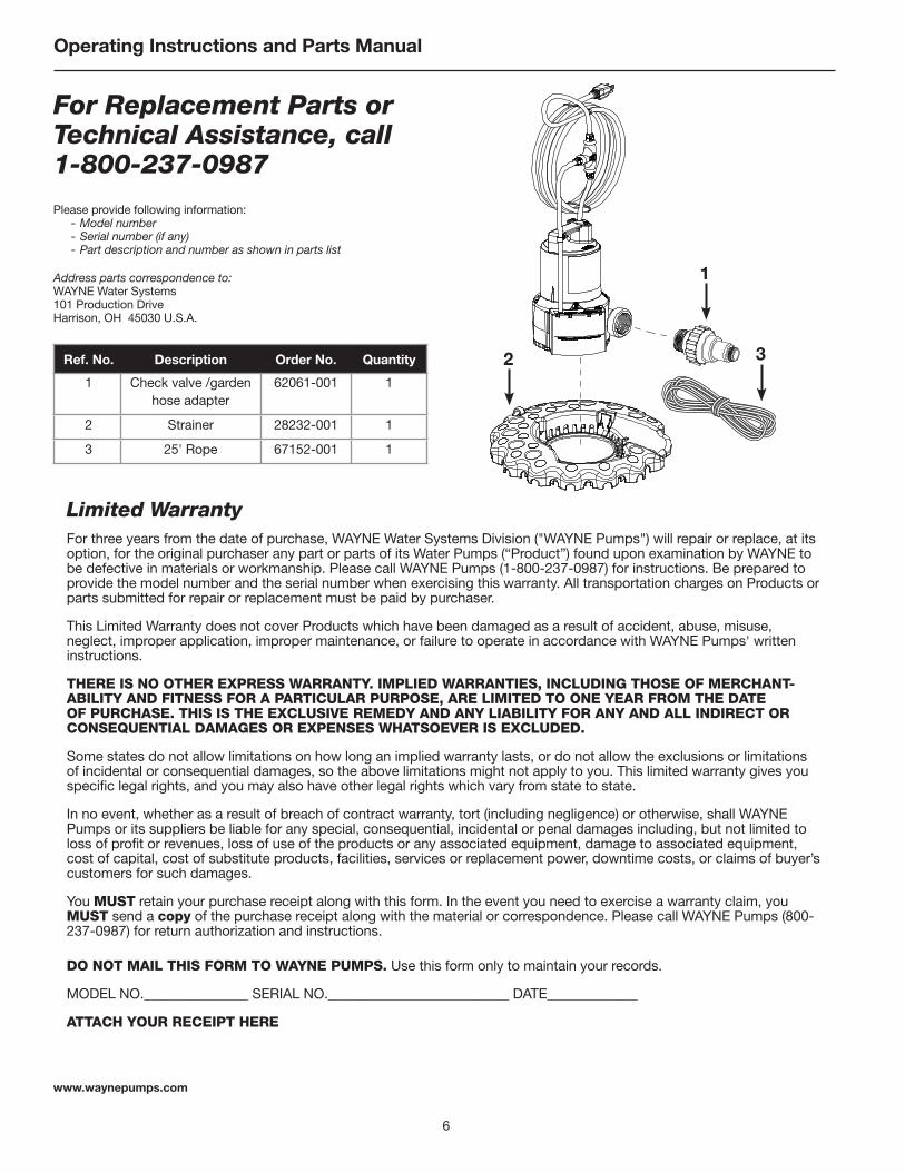
For Replacement Parts or Technical Assistance, call 1-800-237-0987
Please provide following information: - Model number - Serial number (if any) - Part description and number as shown in parts list
Address parts correspondence to:WAYNE Water Systems101 Production DriveHarrison, OH 45030 U.S.A.
Ref. No. Description Order No. Quantity
1 Check valve /garden hose adapter
62061-001 1
2 Strainer 28232-001 1
3 25' Rope 67152-001 1
1
2 3
6
www.waynepumps.com
Operating Instructions and Parts Manual

Notes
7
WAPC250
www.waynepumps.com
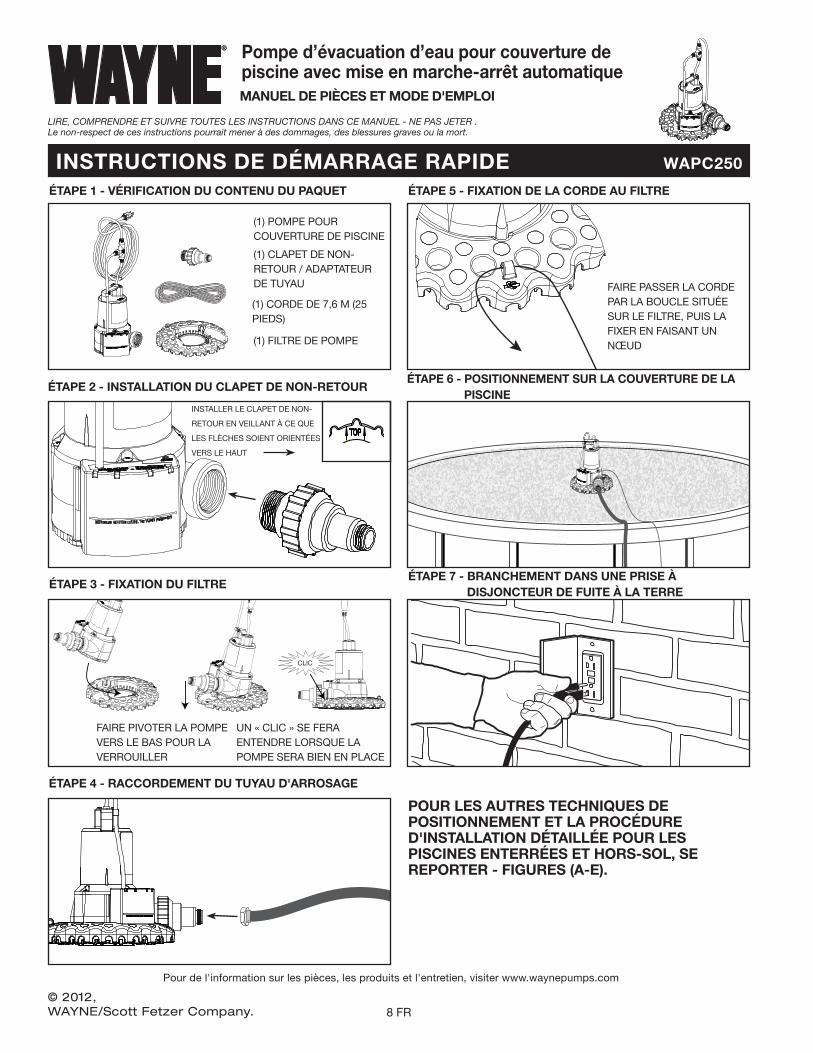
INSTRUCTIONS DE DÉMARRAGE RAPIDE WAPC250
Pour de l'information sur les pièces, les produits et l'entretien, visiter www.waynepumps.com
Pompe d’évacuation d’eau pour couverture de piscine avec mise en marche-arrêt automatiqueMANUEL DE PIÈCES ET MODE D'EMPLOI
LIRE, COMPRENDRE ET SUIVRE TOUTES LES INSTRUCTIONS DANS CE MANUEL - NE PAS JETER . Le non-respect de ces instructions pourrait mener à des dommages, des blessures graves ou la mort.
© 2012, WAYNE/Scott Fetzer Company.
(1) POMPE POUR COUVERTURE DE PISCINE
(1) FILTRE DE POMPE
ÉTAPE 1 - VÉRIFICATION DU CONTENU DU PAQUET
ÉTAPE 2 - INSTALLATION DU CLAPET DE NON-RETOUR
ÉTAPE 3 - FIXATION DU FILTRE
ÉTAPE 4 - RACCORDEMENT DU TUYAU D'ARROSAGE
ÉTAPE 5 - FIXATION DE LA CORDE AU FILTRE
ÉTAPE 6 - POSITIONNEMENT SUR LA COUVERTURE DE LA PISCINE
ÉTAPE 7 - BRANCHEMENT DANS UNE PRISE À DISJONCTEUR DE FUITE À LA TERRE
POUR LES AUTRES TECHNIQUES DE POSITIONNEMENT ET LA PROCÉDURE D'INSTALLATION DÉTAILLÉE POUR LES PISCINES ENTERRÉES ET HORS-SOL, SE REPORTER - FIGURES (A-E).
(1) CLAPET DE NON-RETOUR / ADAPTATEUR DE TUYAU
(1) CORDE DE 7,6 M (25 PIEDS)
FAIRE PIVOTER LA POMPE VERS LE BAS POUR LA VERROUILLER
UN « CLIC » SE FERA ENTENDRE LORSQUE LA POMPE SERA BIEN EN PLACE
FAIRE PASSER LA CORDE PAR LA BOUCLE SITUÉE SUR LE FILTRE, PUIS LA FIXER EN FAISANT UN NŒUD
CLIC
TOP
INSTALLER LE CLAPET DE NON-
RETOUR EN VEILLANT À CE QUE
LES FLÈCHES SOIENT ORIENTÉES
VERS LE HAUT
8 FR