Embed Size (px)
Citation preview
Customer SeviceTechnical Info.Parts & AccessoriesPromotionswww.facebook.com /AntraHelmets
Made in china
AntFi X60 SeriesAuto-Darkening Welding Helmet
User Manual
-1- -2-
Antra X60 SeriesAuto-Darkening Welding Helmet User Manual(2017)
Read and understand this entire instruction manual before attempting to assemble,install, operate or maintain this tool. Failure to comply with the instructions may result in serious personal injury and/or property damage!
The following signal words are used to emphasize safety warnings that must be followed when using this tool:
Indicates an imminently hazardous situation that, if not avoided, WILL result in death or serious injury.
Indicates a potentially hazardous situation that, if not avoided, COULD result in death or serious injury.
Indicates a potentially hazardous situation that, if not avoided, MAY result inminor or moderate injury.
Indicates important information, which if not followed, MAY cause damage to equipment.
IMPORTANT SAFETY INSTRUCTIONSFUMES AND GASES can be hazardous !Welding produces fumes and gases that are hazardous to your health.
• Keep your head out of the fumes. Do not breathe the fumes.• If inside, ventilate the area and/or use exhaust at the arc to remove welding fumes and gases. • If ventilation is poor, use an approved air-supplied respirator.
• Read the manufacturer’s instructions for metals, consumables, coatings, cleaners, and degreasers.
• Do not weld in locations near degreasing cleaning, or spraying operations. The heat and rays of the arc can react with vapors to form highly toxic and irritating gases. • Do not weld on coated metals, such as galvanized, lead, or cadmium plated steel, unless the coating is removed from the weld area, the area is well ventilated, and if necessary, while wearing an air-supplied respirator.The coatings and any metals containing these elements can give off toxic fumes if welded.
California Proposition 65 Warnings !• Welding or cutting equipment produces fumes or gases which contain chemicals known to the State of California to cause birth defects and, in some cases, cancer. (California Health & Safety Code Section 25249.5 et seq.)• This product contains chemicals, including lead, known to the State of California to cause cancer, birth defects, and reproductive harm. Wash hands after handling.
• Work in a confined space only if it is well ventilated, or while wearing an air-supplied respirator. Always have a trained watchperson nearby. Welding fumes and gases can displace air and lower the oxygen level causing injury or death. Be sure the breathing air is safe.
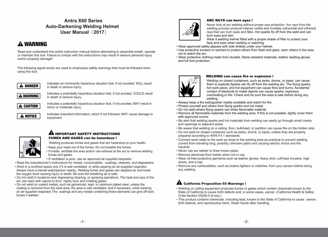
ARC RAYS can burn eyes !Never look at arc welding without proper eye protection. Arc rays from the welding process produce intense visible and invisible (ultraviolet and infrared) rays that can burn eyes and Skin, Hot sparks fly off from the weld and can burn eyes and skin. Wear a welding helmet fitted with a proper shade of filter to protect your face and eyes when welding or watching.
• Wear approved safety glasses with side shields under your helmet.• Use protective screens or barriers to protect others from flash and glare, warn others in the area not to watch the arc.• Wear protective clothing made from durable, flame resistant materials, leather welding gloves and full foot protection.
WELDING can cause fire or explosion !Welding on closed containers, such as tanks, drums, or pipes, can causethem to explode.Sparks can fly off from the welding arc. The flying sparks,hot work piece, and hot equipment can cause fires and burns, Accidentalcontact of electrode to metal objects can cause sparks, explosion, overheating,or fire. Check and be sure the area is sale before doing anywelding.
• Be alert that welding sparks and hot materials from welding can easily go through small cracks and openings to adjacent areas.
• Do not weld on closed containers such as tanks, drums, or pipes; unless they are properly prepared according to AWS F4.1 standards. • Connect work cable to the work as close to the welding area as practical to prevent welding current from traveling long, possibly unknown paths and causing electric shock and fire hazards. • Never use arc welder to thaw frozen pipes.• Remove electrode from holder when not in use.• Wear oil-free protective garments such as leather gloves, heavy shirt, cuff-less trousers, high shoes, and a cap.• Remove any combustibles, such as butane lighters or matches, from your person before doing any welding.
• Always keep a fire extinguisher readily available and watch for fire.• Protect yourself and others from flying sparks and hot metal.• Do not weld where flying sparks can strike flammable material.• Remove all flammable materials from the welding area. If this is not possible, tightly cover them with approved covers
• Be aware that welding on a ceiling ,floor, bulkhead, or partition can cause fire on the hidden side.
-3- -4-
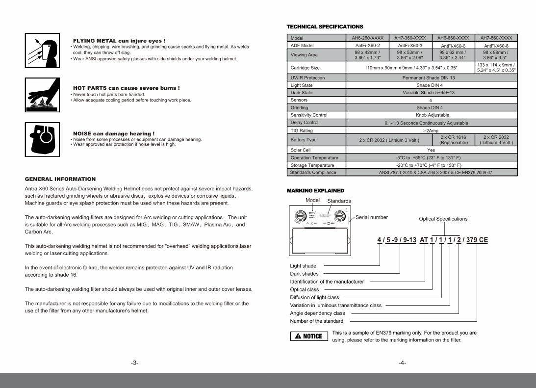
TECHNICAL SPECIFICATIONS
MARKING EXPLAINED
4 / 5 -9 / 9-13 AT 1 / 1 / 1 / 2 / 379 CE
Light shadeDark shadesIdentification of the manufacturerOptical classDiffusion of light classVariation in luminous transmittance classAngle dependency class Number of the standard
Optical Specifications
This is a sample of EN379 marking only. For the product you are using, please refer to the marking information on the filter.
HOT PARTS can cause severe burns !• Never touch hot parts bare handed.• Allow adequate cooling period before touching work piece.
NOISE can damage hearing !• Noise from some processes or equipment can damage hearing.• Wear approved ear protection if noise level is high.
GENERAL INFORMATION
Antra X60 Series Auto-Darkening Welding Helmet does not protect against severe impact hazards,such as fractured grinding wheels or abrasive discs,explosive devices or corrosive liquids.Machine guards or eye splash protection must be used when these hazards are present.
The auto-darkening welding filters are designed for Arc welding or cutting applications.The unit is suitable for all Arc welding processes such as MIG,MAG,TIG,SMAW,Plasma Arc,and Carbon Arc.
This auto-darkening welding helmet is not recommended for "overhead" welding applications,laser welding or Iaser cutting applications.
In the event of electronic failure, the welder remains protected against UV and IR radiation according to shade 16.
The auto-darkening welding filter should always be used with original inner and outer cover lenses.
The manufacturer is not responsible for any failure due to modifications to the welding filter or the use of the filter from any other manufacturer's helmet.
FLYING METAL can injure eyes !
• Wear ANSI approved safety glasses with side shields under your welding helmet.
• Welding, chipping, wire brushing, and grinding cause sparks and flying metal. As welds cool, they can throw off slag.
Standards Model
S/N:XXXXXXXXXXXXXAXXX
Serial number
ModelADF Model
Viewing Area
Cartridge Size
Light StateDark State
UV/IR Protection
Sensors
Grinding
Battery Type
Sensitivity Control
Solar Cell
Delay Control
TIG Rating
Operation Temperature
Storage TemperatureStandards Compliance
AH6-260-XXXX AH7-360-XXXX AH6-660-XXXX AH7-860-XXXXAntFi-X60-2 AntFi-X60-3 AntFi-X60-6 AntFi-X60-898 x 42mm /3.86" x 1.73"
98 x 53mm / 3.86" x 2.09"
98 x 62 mm / 3.86" x 2.44"
98 x 89mm / 3.86" x 3.5"
110mm x 90mm x 9mm / 4.33" x 3.54" x 0.35" 133 x 114 x 9mm /5.24" x 4.5" x 0.35"
Shade DIN 4Variable Shade 5~9/9~13
Permanent Shade DIN 13
Shade DIN 4
2 x CR 2032 ( Lithium 3 Volt ) 2 x CR 2032 ( Lithium 3 Volt )
2 x CR 1616 (Replaceable)
Knob Adjustable
Yes
0.1-1.0 Seconds Continuously Adjustable
-5°C to +55°C (23° F to 131° F)
-20°C to +70°C (-4° F to 158° F)
4
>2Amp
ANSI Z87.1-2010 & CSA Z94.3-2007 & CE EN379:2009-07
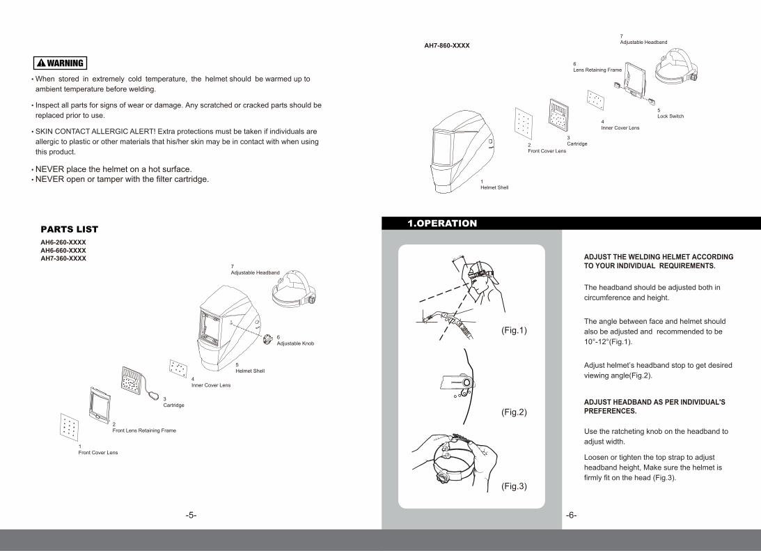
ADJUST THE WELDING HELMET ACCORDING TO YOUR INDIVIDUAL REQUIREMENTS.
The headband should be adjusted both in circumference and height.
The angle between face and helmet should also be adjusted and recommended to be 10°-12°(Fig.1).
1.OPERATION
Adjust helmet’s headband stop to get desiredviewing angle(Fig.2).
(Fig.1)
(Fig.2)
(Fig.3)
Use the ratcheting knob on the headband toadjust width.
ADJUST HEADBAND AS PER INDIVIDUAL'SPREFERENCES.
Loosen or tighten the top strap to adjustheadband height, Make sure the helmet isfirmly fit on the head (Fig.3).
-5- -6-
PARTS LIST
• NEVER place the helmet on a hot surface.• NEVER open or tamper with the filter cartridge.
• Inspect all parts for signs of wear or damage. Any scratched or cracked parts should be replaced prior to use.
• When stored in extremely cold temperature, the helmet should be warmed up to ambient temperature before welding.
• SKIN CONTACT ALLERGIC ALERT! Extra protections must be taken if individuals are allergic to plastic or other materials that his/her skin may be in contact with when using this product.
AH6-260-XXXX
5Helmet Shell
6Adjustable Knob
1Front Cover Lens
3Cartridge
4Inner Cover Lens
2Front Lens Retaining Frame
7Adjustable Headband
1Helmet Shell
2Front Cover Lens
3Cartridge
4Inner Cover Lens
6Lens Retaining Frame
7Adjustable Headband
5Lock Switch
AH7-860-XXXX
AH6-660-XXXXAH7-360-XXXX
-7-
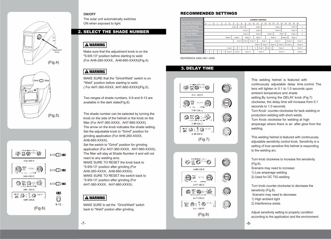
2. SELECT THE SHADE NUMBER
RECOMMENDED SETTINGS
REFERENCE ANSI Z49.1-2005
9876 10
Shade 8
Shade 5
Shade 9 Shade 10
Shade 11 Shade 12 Shade 13 Shade 14 Shade 15
Shade 11 Shade 12 Shade 13 Shade 14
Shade 12 Shade 14
Shade 15
Shade 11
Shade 13Shade 12Shade 11Shade 10 Shade 14
The shade number can be selected by turning the knob on the side of the helmet or the knob on the filter (For AH7-360-XXXX, AH7-860-XXXX) The arrow on the knob indicates the shade setting.Set the adjustable knob to "Grind" position for grinding application (For AH6-260-XXXX, AH6-660-XXXX).Set the switch to "Grind" position for grinding application (For AH7-360-XXXX, AH7-860-XXXX).The filter will stay at Shade Number 4 and will not react to any welding arcs.MAKE SURE TO RESET the knob back to “5-9/9-13” position after grinding (For AH6-260-XXXX, AH6-660-XXXX).MAKE SURE TO RESET the switch back to “5-9/9-13” position after grinding (For AH7-360-XXXX, AH7-860-XXXX).
The solar unit automatically switches ON when exposed to light.
Two ranges of shade numbers, 5-9 and 9-13 areavailable in the dark state(Fig.6).
ON/OFF
This welding helmet is featured with continuously adjustable delay time control. The lens will lighten in 0.1 to 1.0 seconds upon ambient temperature and shadesetting.By turning the DELAY knob (Fig.7) clockwise, the delay time will increase from 0.1 seconds to 1.0 seconds.Turn Knob counter-clockwise for tack welding or production welding with short welds. Turn Knob clockwise for welding at high amperage where there is an after glow from the welding.
-8-
MAKE SURE that the “Grind/Weld” switch is on“Weld” position before starting to weld( For AH7-360-XXXX, AH7-860-XXXX)(Fig.5).
Make sure that the adjustment knob is on the "5-9/9-13" position before starting to weld(For AH6-260-XXXX, AH6-660-XXXX)(Fig.4).
MAKE SURE to set the "Grind/Weld" switch back to "Weld" postion after grinding.
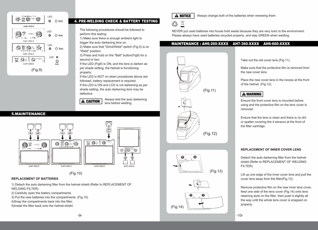
This welding helmet is featured with continuously adjustable sensitivity control knob. Sensitivity is a setting of how sensitive this helmet is responding to the welding arc.
Turn knob clockwise to increase the sensitivity (Fig.8).Scenario may need to increase: 1) Low amperage welding2) Used for DC TIG welding
Turn knob counter-clockwise to decrease the sensitivity (Fig.8). Scenario may need to decrease:1) High ambient light2) Interference exists
Adjust sensitivity setting to properly condition according to the application and the environment.
(Fig.4)
AdjustmentKnob
(Fig.5)
Grind Weld5-99-13Batt.
3. DELAY TIME
AntFi-X60-3
AntFi-X60-2
AntFi-X60-8
AntFi-X60-6
AntFi-X60-3
AntFi-X60-2
AntFi-X60-8
AntFi-X60-6
(Fig.7)
AntFi-X60-3
AntFi-X60-2
AntFi-X60-8
AntFi-X60-6(Fig.6)(Fig.8)
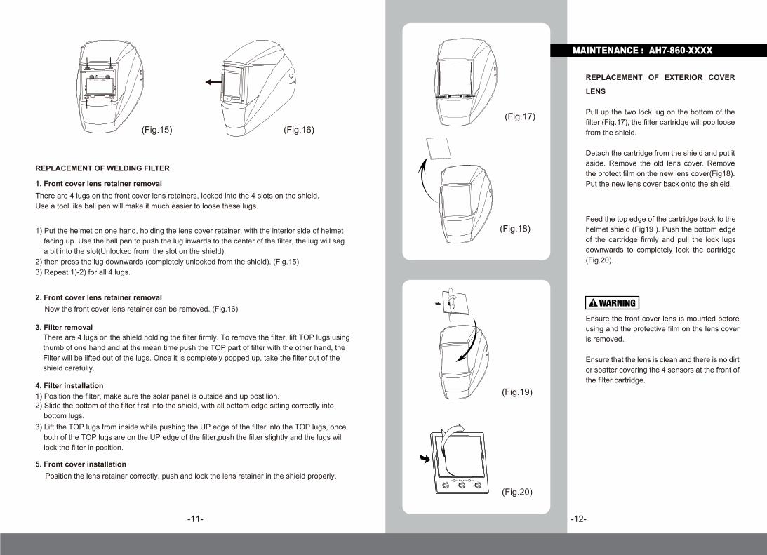
REPLACEMENT OF BATTERIES
1) Detach the auto darkening filter from the helmet shield (Refer to REPLACEMENT OF WELDING FILTER)2) Carefully open the battery compartments. 3) Put the new batteries into the compartments. (Fig.10)4)Snap the compartments back into the filter.5)Install the filter back onto the helmet shield.
5.MAINTENANCE
-9- -10-
4. PRE-WELDING CHECK & BATTERY TESTING
The following procedures should be followed to perform this testing:1) Make sure there is enough ambient light to trigger the auto darkening lens on. 2) Make sure that "Grind/Weld" switch (Fig.5) is on "Weld" position.3) Press and hold on the "Batt" button(Fig9) for a second or two:If the LED (Fig9) is ON, and the lens is darken as per shade setting, the helmet is functioning properly. If the LED is NOT on when procedures above are followed, battery replacement is required. If the LED is ON and LCD is not darkening as per shade setting, the auto darkening lens may be defective.
Always test the auto darkeninglens before welding.
NEVER put used batteries into house hold waste because they are very toxic to the environment. Please always have used batteries recycled properly, and stay GREEN when welding.
Always change both of the batteries when renewing them.
AntFi-X60-3
AntFi-X60-2
AntFi-X60-8
AntFi-X60-6
++
AntFi-X60-3
++
AntFi-X60-6
++
AntFi-X60-2 AntFi-X60-8
(Fig.9)
(Fig.10)
Take out the old cover lens (Fig.11).
Make sure that the protective film is removed from the new cover lens.
Place the new cover lens in the recess at the frontof the helmet (Fig.12).
Ensure the front cover lens is mounted before using and the protective film on the lens cover is removed.
Ensure that the lens is clean and there is no dirt or spatter covering the 4 sensors at the front of the filter cartridge.
REPLACEMENT OF INNER COVER LENS
Detach the auto darkening filter from the helmet shield (Refer to REPLACEMENT OF WELDING FILTER).
Lift up one edge of the inner cover lens and pull the cover lens away from the filter(Fig.13).
Remove protective film on the new inner lens cover, feed one side of the lens cover (Fig.14) onto lens retaining slots on the filter, then push it slightly all the way until the whole lens cover is snapped on properly.
(Fig.11)
(Fig.12)
MAINTENANCE : AH6-260-XXXX AH7-360-XXXX AH6-660-XXXX
LED
LED
LED
LED
(Fig.13)
(Fig.14)
-11- -12-
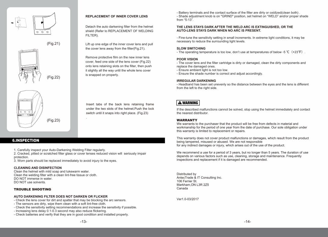
(Fig.15) (Fig.16)
REPLACEMENT OF WELDING FILTER
1. Front cover lens retainer removalThere are 4 lugs on the front cover lens retainers, locked into the 4 slots on the shield. Use a tool like ball pen will make it much easier to loose these lugs.
1) Put the helmet on one hand, holding the lens cover retainer, with the interior side of helmet facing up. Use the ball pen to push the lug inwards to the center of the filter, the lug will sag a bit into the slot(Unlocked from the slot on the shield),2) then press the lug downwards (completely unlocked from the shield). (Fig.15)3) Repeat 1)-2) for all 4 lugs.
2. Front cover lens retainer removal Now the front cover lens retainer can be removed. (Fig.16)
3. Filter removalThere are 4 lugs on the shield holding the filter firmly. To remove the filter, lift TOP lugs using thumb of one hand and at the mean time push the TOP part of filter with the other hand, theFilter will be lifted out of the lugs. Once it is completely popped up, take the filter out of the shield carefully.
4. Filter installation1) Position the filter, make sure the solar panel is outside and up postilion. 2) Slide the bottom of the filter first into the shield, with all bottom edge sitting correctly into bottom lugs. 3) Lift the TOP lugs from inside while pushing the UP edge of the filter into the TOP lugs, once both of the TOP lugs are on the UP edge of the filter,push the filter slightly and the lugs will lock the filter in position.
5. Front cover installationPosition the lens retainer correctly, push and lock the lens retainer in the shield properly.
REPLACEMENT OF EXTERIOR COVER
LENS
Pull up the two lock lug on the bottom of the filter (Fig.17), the filter cartridge will pop loose from the shield.
Detach the cartridge from the shield and put it aside. Remove the old lens cover. Remove the protect film on the new lens cover(Fig18). Put the new lens cover back onto the shield.
(Fig.19)
(Fig.20)
(Fig.17)
(Fig.18)
MAINTENANCE : AH7-860-XXXX
Feed the top edge of the cartridge back to the helmet shield (Fig19 ). Push the bottom edge of the cartridge firmly and pull the lock lugs downwards to completely lock the cartridge (Fig.20).
Ensure the front cover lens is mounted before using and the protective film on the lens cover is removed.
Ensure that the lens is clean and there is no dirt or spatter covering the 4 sensors at the front of the filter cartridge.
-13-
1. Carefully inspect your Auto-Darkening Welding Filter regularly.2. Cracked, pitted or scratched filter glass or cover lenses reduced vision will seriously impair protection. 3. Worn parts should be replaced immediately to avoid injury to the eyes.
CLEANING AND DISINFECTION Clean the helmet with mild soap and lukewarm water. Clean the welding filter with a clean lint-free tissue or cloth. DO NOT immerse in water. DO NOT use solvents.
TROUBLE SHOOTING
AUTO DARKENING FILTER DOES NOT DARKEN OR FLICKER- Check the lens cover for dirt and spatter that may be blocking the arc sensors.- The sensors are dirty, wipe them clean with a soft lint-free cloth. - Check the sensitivity setting recommendations and increase the sensitivity if possible. - Increasing lens delay 0.1-0.3 second may also reduce flickering.- Check batteries and verify that they are in good condition and installed properly.
- Battery terminals and the contact surface of the filter are dirty or oxidized(clean both) .- Shade adjustment knob is on "GRIND" position, set helmet on “WELD” and/or proper shade from “5-13”.
THE LENS STAYS DARK AFTER THE WELD ARC IS EXTINGUISHED, OR THEAUTO-LENS STAYS DARK WHEN NO ARC IS PRESENT.
- Fine-tune the sensitivity setting in small increments. In extreme light conditions, it may be necessary to reduce the surrounding light levels.
SLOW SWITCHING- The operating temperature is too low, don’t use at temperatures of below -5 ℃(+23℉).
POOR VISION- The cover lens and the filter cartridge is dirty or damaged, clean the dirty components and replace the damaged ones.- Ensure ambient light is not too low.- Ensure the shade number is correct and adjust accordingly.
IRREGULAR DARKENING- Headband has been set unevenly so the distance between the eyes and the lens is different from the left to the right side.
If the described malfunctions cannot be solved, stop using the helmet immediately and contact the nearest distributor.
WARRANTYWe warrants to the purchaser that the product will be free from defects in material and workmanship for the period of one year from the date of purchase. Our sole obligation under this warranty is limited to replacement or repairs.
This warranty does not cover product malfunctions or damages, which result from the product being tampered, misused or abused. We are not responsible for any indirect damages or injury, which arises out of the use of the product.
We recommend a use for a period of 3 years, but no longer than 5 years. The duration of use depends on various factors such as use, cleaning, storage and maintenance. Frequently inspections and replacement if it is damaged are recommended.
Distributed by AntecTrade & IT Consulting Inc.106 Ferrier St.Markham,ON L3R 2Z5Canada
Ver1.0-03/2017
Insert tabs of the back lens retaining frame under the two slots of the helmet.Push the lock switch until it snaps into right place. (Fig.23).
-14-
(Fig.21)
(Fig.22)
REPLACEMENT OF INNER COVER LENS
Detach the auto darkening filter from the helmet shield (Refer to REPLACEMENT OF WELDING FILTER).
Lift up one edge of the inner cover lens and pull the cover lens away from the filter(Fig.21).
Remove protective film on the new inner lens cover, feed one side of the lens cover (Fig.22) onto lens retaining slots on the filter, then push it slightly all the way until the whole lens cover is snapped on properly.
6.INSPECTION
(Fig.23)