Embed Size (px)
Citation preview

This article appeared in a journal published by Elsevier. The attachedcopy is furnished to the author for internal non-commercial researchand education use, including for instruction at the authors institution
and sharing with colleagues.
Other uses, including reproduction and distribution, or selling orlicensing copies, or posting to personal, institutional or third party
websites are prohibited.
In most cases authors are permitted to post their version of thearticle (e.g. in Word or Tex form) to their personal website orinstitutional repository. Authors requiring further information
regarding Elsevier’s archiving and manuscript policies areencouraged to visit:
http://www.elsevier.com/copyright
Author's personal copy
Behavior of a rhombus frame of nonlinear elastic material underlarge deflection
Nasim Shatarat a,�, Samir Al-Sadder a, Hasan Katkhuda a, Husam Qablan a, Anis Shatnawi b
a Department of Civil Engineering, Faculty of Engineering, Hashemite University, Zarka 13115, Jordanb Department of Civil Engineering, Faculty of Engineering, The University of Jordan, Amman 11942, Jordan
a r t i c l e i n f o
Article history:
Received 11 October 2008
Received in revised form
23 November 2008
Accepted 4 December 2008Available online 10 December 2008
Keywords:
ADINA
Analytical solution
Large deflection
Nonlinear elastic material
Rhombus frame
a b s t r a c t
The large-deflection spring behavior of an inextensible thin rhombus frame is studied in this work. The
frame has a rectangular cross-section and supports two equal and opposite diagonal forces that act on
its two opposite corners with a given apex angle g. Both geometrical and material nonlinearities have
been considered in the study. The beam was assumed to be made of a material having a nonlinear
stress–strain relationship of the Ludwick type.
A semi-analytical solution has been formulated for the relation between the large displacement at
the corners of the frame and the applied forces. The deformed shapes and the nonlinear secant
stiffnesses of the rhombus frame were plotted against applied loads. The frame behavior was fully
investigated for different apex angles and nonlinear elastic material constants, n.
In order to check the accuracy and efficiency of the proposed analytical solution, a large-
displacement finite-element analysis utilizing the multi-purpose computer program ADINA was
performed. Each side of the rhombus frame was divided into 10 moment–curvature beam elements.
Results obtained using the analytical solution were identical to the results obtained using the software
ADINA.
& 2008 Elsevier Ltd. All rights reserved.
1. Introduction
Highly flexible elements are widely used in precisionmechanics, especially in aerospace products and biomedicalinstrumentations, where high strain and fatigue capabilities arerequired. Examples of such elements include flexural pivots,parallel spring translators, flexible linking devices, nonlinearmechanical springs, compliant gripper elements and microelec-tromechanical (MEMS) devices. The increasing use of suchelements requires a better understanding of their behavior underlarge deflection.
Most of the applications of nonlinear bending theory to thinbeams have been confined to beams of linear elastic materials[1–16]. Fewer studies are available for large deflections of beamsmade of a nonlinear elastic material. Oden and Childs [17] studiedthe nonlinear post-buckling behavior of a thin prismatic canti-lever beam. The nonlinear elastic material was modeled using amoment–curvature relationship in the form of hyperbolic tangentlaw. Parathep and Varadan [18] investigated the inelastic largedeflection of a prismatic cantilever beam with a rectangular cross-section subjected to a vertical point load applied at the free end.
The material of the beam was considered to have a stress–strainlaw of the Ramberg–Osgood type. Monasa [19] studied the effectof material nonlinearity on the stability behavior of a thinprismatic cantilever column. The material of the column wasrepresented by a logarithmic stress–strain function. Lewis andMonasa [20] solved the large-deflection problem of a slenderprismatic cantilever beam subjected to a tip vertical load using anumerical integration technique. The stress–strain relationship ofthe nonlinear material used was of a Ludwick type.
Furthermore, Yu and Johnson [21] investigated the post-buckling elastic–plastic deformation of a strut. The researchersextended the theory of elastica [22] to determine the shapeof a strut undergoing large plastic deflection. The equationsgoverning such a behavior, known as the plastica [21] equations,were set up and solved by a perturbation method and bynumerical integration. Lewis et al. [23] investigated the large-deflection and stability behavior of a vertical slender columnof elastic–plastic material subjected to uniformly distributedloads, including its own weight, using the variational approach.Luan and Yu [24] studied the elastic–plastic large-deflectionanalysis of cantilever beams subjected to an inclined tipconcentrated load. Fertis and Lee [25] and Fertis [26] studiedthe complicated nonlinear elastic problem of prismatic andnonprismatic inextensible beams using the method of equivalentsystems.
ARTICLE IN PRESS
Contents lists available at ScienceDirect
journal homepage: www.elsevier.com/locate/ijmecsci
International Journal of Mechanical Sciences
0020-7403/$ - see front matter & 2008 Elsevier Ltd. All rights reserved.
doi:10.1016/j.ijmecsci.2008.12.001
� Corresponding author. Tel.: +962 795427700.
E-mail address: [email protected] (N. Shatarat).
International Journal of Mechanical Sciences 51 (2009) 166–177
Author's personal copy
Recently, Lee [27] solved the large-deflection problem of aslender prismatic cantilever of a Ludwick-type material subjectedto a uniformly distributed load and a tip vertical load using anumerical integration technique. Huang et al. [28] considered thelarge-deflection behavior of elastic–plastic, nonlinear strain-hardening cantilevers of rectangular cross-sections, for whichthe stress–strain relationship after yielding is described by aLudwick relation. Al-Sadder and Shatarat [29] investigated thelarge-deflection behavior of a prismatic composite cantileverbeam made of two different nonlinear elastic materials andsubjected to an inclined tip concentrated force.
The literature survey presented above shows that the large-deflection problem of linear elastic and nonlinear elastic beamshas been extensively studied. However, published literatureshows that the large-deflection problem of highly flexible frameshas received little attention. Jenkins et al. [30] analyzed the large-deflection behavior of a diamond-shaped prismatic frame loadeddiagonally at two corners. Theocaris and Panayotounakos [31]studied the large-deflection analysis of flexible portal type frames.Thacker et al. [32] investigated the behavior of a rectangular framewith rigid top and base, but with highly flexible prismatic sidecolumns. The governing differential equations were integrated byhomotopy and quasi-Newton methods. Wang [33] studied thenonlinear deformation of a loaded pinned–pinned triangularprismatic frame with an internal hinge at its apex. Ohtsukia andEllyin [34] analyzed a square prismatic frame with rigid jointsloaded diagonally. The analytical solution of the large-deflectionproblem was obtained using elliptic integrals. Dado and Al-Sadder[35] dealt with the elastic spring behavior of a rhombus frameconsisting of nonprismatic members. The relations between thelarge displacement at the corners and the applied forces wereobtained using a new robust numerical technique.
The rhombus frame has sometimes been referred to as a ‘‘halfpantograph’’ in MEMS systems. Nielson and Howell [36] investi-gated the use of the pseudorigid body model (PRBM) to designfully compliant micro-half-pantographs. The PRBM was used todevelop equations for input–output displacement, force–deflec-tion and maximum nominal stress–deflection predictions.
To the authors’ knowledge, the large-deflection behavior ofhighly flexible frames having nonlinear elastic material has notbeen yet studied. This study deals with the large-deflectionbehavior of a rhombus frame having a solid rectangular cross-section with rigid joints. The rhombus frame is built up from anonlinear Ludwick-type elastic material and is subjected to twoopposite diagonal forces depicting a spring action. The differentialequations governing the large-deflection behavior of the frame areformulated and solved. The solution is compared with the resultsobtained by the software ADINA [37]. The load–deflection curves,the deformed configurations and the nonlinear stiffness of thespring behavior are obtained for different nonlinear elasticmaterial constants, n, and apex angles, g.
2. Problem description
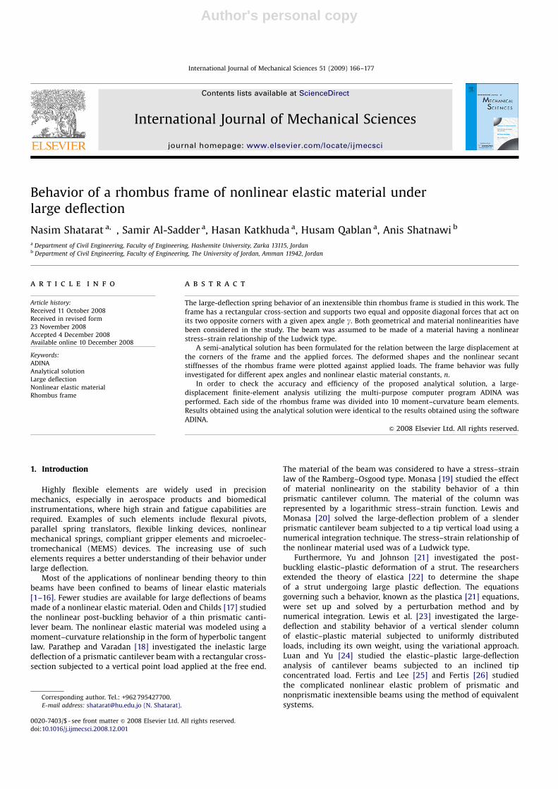
A slender inextensible rhombus frame with rigid joints havingside lengths equal to 2L is subjected to a diagonal tension orcompression force equal to 2P acting at point C, as shown in Fig. 1.Point A of the frame is held in position by a pin support. The sidelength of the rhombus makes an angle b with the x-axis, as shownin Fig. 1. The sides of the rhombus are rigidly jointed together sothat the interior angle g remains fixed regardless of the appliedload or the deformation. Each side length of the rhombus framehas a solid rectangular cross-section and is made of a nonlinearLudwick-type elastic material. The stress–strain relationship ofsuch a material is of a power-law form [20] and can be expressed
by a nonlinear function as follows:
s ¼ B�n (1)
where s and e represent the stress and strain, respectively; B andn are constants that depend on the mechanical properties of thematerial.
3. Theoretical formulation
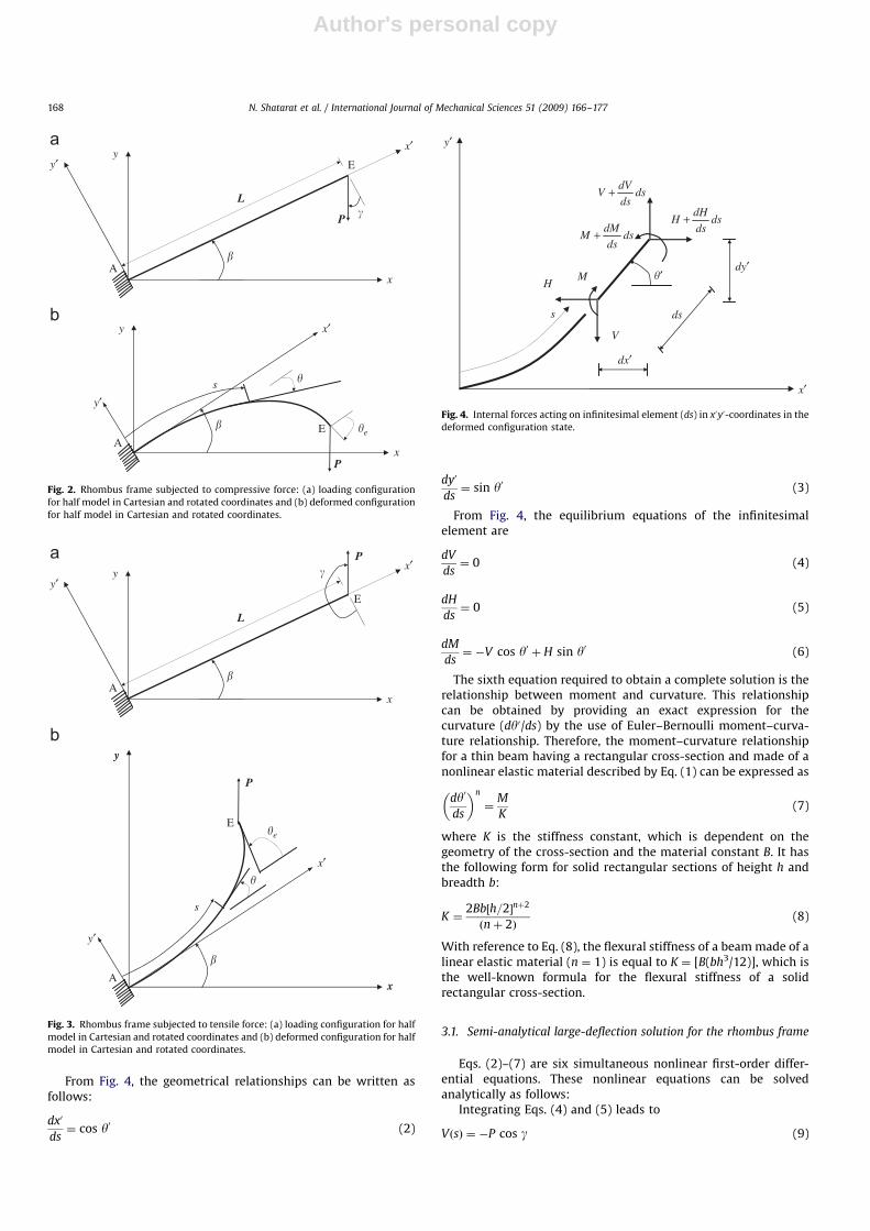
It is sufficient to investigate the behavior of a half-side memberof the frame since the frame shown in Fig. 1 is doubly symmetricand the members of the frame are rigidly connected to eachother. These two factors support the existence of an inflectionpoint at the center of each side member. Therefore, a half-sidemember of the frame will be analyzed and the complete framebehavior will be constructed from the double symmetry. Figs. 2and 3 show the half-side model of member AE for the rhombusframe under compression and tension in the Cartesian androtated axes, respectively. The formulations of the governingdifferential equations are performed for the compression case inthe rotated axes for simplicity and then generalized for thetension case.
An infinitesimal element of the beam having a length, ds, isshown in Fig. 4. The element is under the action of three internalforces: a horizontal force, H, a vertical force, V, and an internalbending moment, M. The coordinates of a point on this beam aredenoted by x0 and y0. Angle y0 is the slope of the beam measuredfrom the positive x0-axis to the tangent of the correspondingpoint. The convective coordinate, s, is the curved coordinatealong the deformed length of the beam. Hence, six unknowns canbe identified: H, V, M, x0, y0 and y0. All these unknowns arefunctions of s.
ARTICLE IN PRESS
y
2P
2L
�
x
C
BD
A
Rigid Joint
L
Inflection Point
E
Fig. 1. Rhombus frame subjected to a tension or a compressive force.
N. Shatarat et al. / International Journal of Mechanical Sciences 51 (2009) 166–177 167
Author's personal copy
From Fig. 4, the geometrical relationships can be written asfollows:
dx0
ds¼ cos y0 (2)
dy0
ds¼ sin y0 (3)
From Fig. 4, the equilibrium equations of the infinitesimalelement are
dV
ds¼ 0 (4)
dH
ds¼ 0 (5)
dM
ds¼ �V cos y0 þ H sin y0 (6)
The sixth equation required to obtain a complete solution is therelationship between moment and curvature. This relationshipcan be obtained by providing an exact expression for thecurvature (dy0/ds) by the use of Euler–Bernoulli moment–curva-ture relationship. Therefore, the moment–curvature relationshipfor a thin beam having a rectangular cross-section and made of anonlinear elastic material described by Eq. (1) can be expressed as
dy0
ds
� �n
¼M
K(7)
where K is the stiffness constant, which is dependent on thegeometry of the cross-section and the material constant B. It hasthe following form for solid rectangular sections of height h andbreadth b:
K ¼2Bb½h=2�nþ2
ðnþ 2Þ(8)
With reference to Eq. (8), the flexural stiffness of a beam made of alinear elastic material (n ¼ 1) is equal to K ¼ [B(bh3/12)], which isthe well-known formula for the flexural stiffness of a solidrectangular cross-section.
3.1. Semi-analytical large-deflection solution for the rhombus frame
Eqs. (2)–(7) are six simultaneous nonlinear first-order differ-ential equations. These nonlinear equations can be solvedanalytically as follows:
Integrating Eqs. (4) and (5) leads to
VðsÞ ¼ �P cos g (9)
ARTICLE IN PRESS
x
y
�
x′y′
P
L
E
A
EA
s
�e
x′
y′
P
�
�
x
y
�
Fig. 2. Rhombus frame subjected to compressive force: (a) loading configuration
for half model in Cartesian and rotated coordinates and (b) deformed configuration
for half model in Cartesian and rotated coordinates.
x
y
�
x′y′
P
L
E
A
E
A
s
�e
x′
y′
P
�
�
x
y
�
Fig. 3. Rhombus frame subjected to tensile force: (a) loading configuration for half
model in Cartesian and rotated coordinates and (b) deformed configuration for half
model in Cartesian and rotated coordinates.
dy′
dsds
dHH +
y′
x′
dx′
V
HM
dsds
dVV +
dsds
dMM +
s ds
�′
Fig. 4. Internal forces acting on infinitesimal element (ds) in x0y0-coordinates in the
deformed configuration state.
N. Shatarat et al. / International Journal of Mechanical Sciences 51 (2009) 166–177168
Author's personal copy
HðsÞ ¼ �P sin g (10)
where g ¼ b, as shown in Fig. 2. Substituting Eqs. (9) and (10) intoEq. (6) gives
dM
ds¼ P cosðgþ y0Þ (11)
Differentiating Eq. (7) once with respect to s gives
ndy0
ds
� �n�1
¼1
K
dM
ds(12)
Substituting Eq. (11) into Eq. (12) gives
ndyds
� �n�1
¼P
Kcosðgþ y0Þ (13)
Multiplying both sides of Eq. (13) by dy0/ds it yields
ndy0
ds
� �n�1dy0
ds¼
P
Kcosðgþ y0Þ
dy0
ds(14)
or
ndy0
ds
� �n
¼P
Kcosðgþ y0Þ
dy0
ds(15)
Integrating Eq. (15) once with respect to s gives
n
nþ 1
dy0
ds
� �nþ1
¼P
Ksinðgþ y0Þ þ C1 (16)
The constant of integration, C1, can be obtained by applying theend condition at s ¼ L, where the bending moment is equal tozero, such that dy0/ds ¼ 0, resulting in
C1 ¼ �P
Ksinðgþ yeÞ (17)
where ye is the angle of rotation at the tip of the member AE asshown in Fig. 2. Substituting Eq. (17) into Eq. (16) gives
n
nþ 1
dy0
ds
� �nþ1
¼P
K½sinðgþ y0Þ � sinðgþ yeÞ� (18)
or
dy0
ds¼ P1=nþ1 nþ 1
nK
� �1=ðnþ1Þ
(19)
In order to find the required force P for a given tip angle ofrotation ye, Eq. (19) has to be applied at the free end of thecantilever (point E in Fig. 2) and the following expression isobtained:
P ¼1
L
Z ye
0
nþ 1
nK½sinðgþ y0Þ � sinðgþ yeÞ�
� ��1=ðnþ1Þ
dy0" #nþ1
(20)
Now, after calculating the required force P for a givenye, the curved coordinate s must be obtained as a functionof intermediate angle of rotation yi as follows. RecallEq. (19):
dy0
ds¼ P1=ðnþ1Þ nþ 1
nK½sinðgþ y0Þ � sinðgþ yeÞ�
� �1=ðnþ1Þ
(21)
or
ds ¼ P�1=ðnþ1Þ nþ 1
nK½sinðgþ y0Þ � sinðgþ yeÞ�
� ��1=ðnþ1Þ
dy0 (22)
Integrating Eq. (22) once with respect to s gives
sðyiÞ ¼
Z yi
0P�1=ðnþ1Þ nþ 1
nK½sinðgþ y0Þ � sinðgþ yeÞ�
� ��1=ðnþ1Þ
dy0
(23)
Using Eqs. (2) and (19), an expression for the coordinate isobtained as follows:
x0ðyiÞ ¼
Z yi
0
cos y0 dy0
P1=ðnþ1Þfðnþ 1Þ=nK½sinðgþ y0Þ � sinðgþ yeÞ�g
1=ðnþ1Þ
(24)
Similarly an expression for the coordinate y0 is obtained:
y0ðyiÞ ¼
Z yi
0
siny0 dy0
P1=ðnþ1Þfðnþ 1Þ=nK½sinðgþ y0Þ � sinðgþ yeÞ�g
1=ðnþ1Þ
(25)
The Cartesian coordinates x and y are obtained using simpletransformation relations as follows:
xðyiÞ ¼ x0ðyiÞ cos b� y0ðyiÞ sin b (26)
yðyiÞ ¼ x0ðyiÞ sin bþ y0ðyiÞ cos b (27)
The tip displacement at point E in Cartesian coordinates are given by
xE ¼ xðyeÞ (28)
yE ¼ yðyeÞ (29)
The bending moment M is obtained by substituting Eq. (19) intoEq. (7) so that
MðyiÞ ¼ KPn=ðnþ1Þ nþ 1
nK½sinðgþ yiÞ � sinðgþ yeÞ�
� �n=ðnþ1Þ
(30)
Eqs. (20), (23)–(25) and (30) apply for the case of applied compressiveforce. Similarly, one may obtain the relations for the case of appliedtension force by letting the angle g ¼ b+p as shown in Fig. 3.
Further analysis was performed by applying numericalintegration. Sixth-order Runge–Kutta algorithm was applied inorder to integrate Eqs. (4), (5) and (9) using the followingboundary conditions: x, y and y are equal to zero at s ¼ 0.
4. Non-dimensional parameters
One good engineering application of this rhombus frame is toobtain a nonlinear stiffness behavior with favorable character-istics. Therefore, the following non-dimensional parameters aredefined:
(1) The non-dimensional horizontal and vertical coordinates are
xn ¼x
2L; yn ¼
y
2L; (31)
(2) The non-dimensional load (2P) is
an ¼ð2PÞð2LÞ2
Ke(32)
where
Ke ¼ Kjn¼1 ¼ Bbh3
12(33)
and Ke is the elastic secant stiffness in the direction of theload.
(3) The non-dimensional total deflection parameter in thedirection of the load is
dC ¼4ðyE � L sin bÞ
2L(34a)
and the non-dimensional relative displacement of point Bwith respect to point D is
dBD ¼2xE
2L(34b)
ARTICLE IN PRESS
N. Shatarat et al. / International Journal of Mechanical Sciences 51 (2009) 166–177 169
Author's personal copyARTICLE IN PRESS
-2
-50
-40
-30
-20
-10
0
-2
-150
-125
-100
-75
-50
-25
0
-2
-360
-300
-240
-180
-120
-60
0-2
-1200
-1000
-800
-600
-400
-200
0
β = 75°
60°
45°
30°
15°
60°
45°
30°
15°
75°60°
45°
30°
15°
60°45°
30°15°
75°
75°
α n
δC
-1.6 -1.2 -0.8 -0.4 0 -1.6 -1.2 -0.8 -0.4 0
-1.6 -1.2 -0.8 -0.4 0 -1.6 -1.2 -0.8 -0.4 0
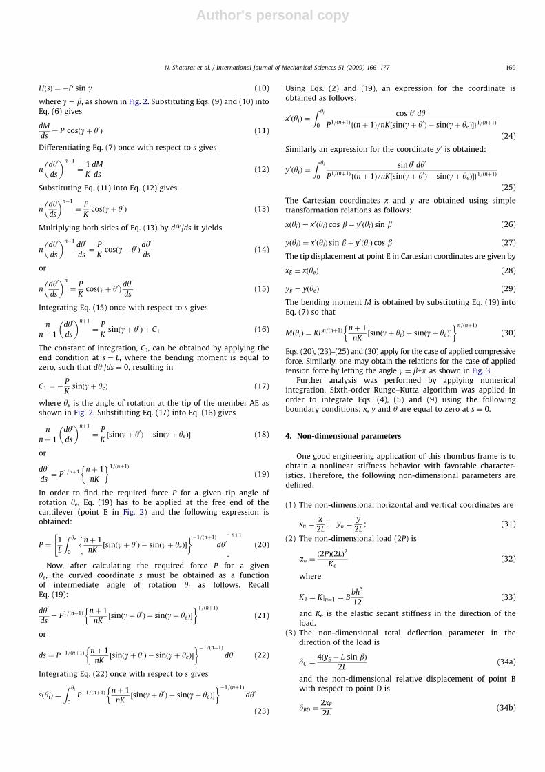
Fig. 5. Load versus vertical deflection curves for different apex angles and n-values: (a) n ¼ 1.0, (b) n ¼ 0.7, (c) n ¼ 0.5 and (d) n ¼ 0.3 (compression case).
0
0
40
80
120
160
200
240
0
0
500
1000
1500
2000
2500
0
0
3000
6000
9000
12000
15000
00
10000
20000
30000
40000
50000
60000
70000
β = 75°60° 45° 30° 15° 75°
60°
30° 15°
45°
75°
60°
30°15°
60°
45°30°
15°
75°
45°
α n
δC
0.4 0.8 1.2 1.6 0.4 0.8 1.2 1.6
0.4 0.8 1.2 1.6 0.4 0.8 1.2 1.6
Fig. 6. Load versus vertical deflection curves for different apex angles and n-values: (a) n ¼ 1.0, (b) n ¼ 0.7, (c) n ¼ 0.5 and (d) n ¼ 0.3 (tension case).
N. Shatarat et al. / International Journal of Mechanical Sciences 51 (2009) 166–177170
Author's personal copyARTICLE IN PRESS
0
-50
-40
-30
-20
-10
0
0
-150
-125
-100
-75
-50
-25
0
0
-360
-300
-240
-180
-120
-60
0
0
-1200
-1000
-800
-600
-400
-200
0
β = 75°
60°
45°
30°
15°
60°
45°
30°
15°
75°
60°
45°30°
15°
60°45°30°
15°
75°
75°
α n
δBD
0.4 0.8 1.2 1.6 0.4 0.8 1.2 1.6
0.4 0.8 1.2 1.6 0.4 0.8 1.2 1.6
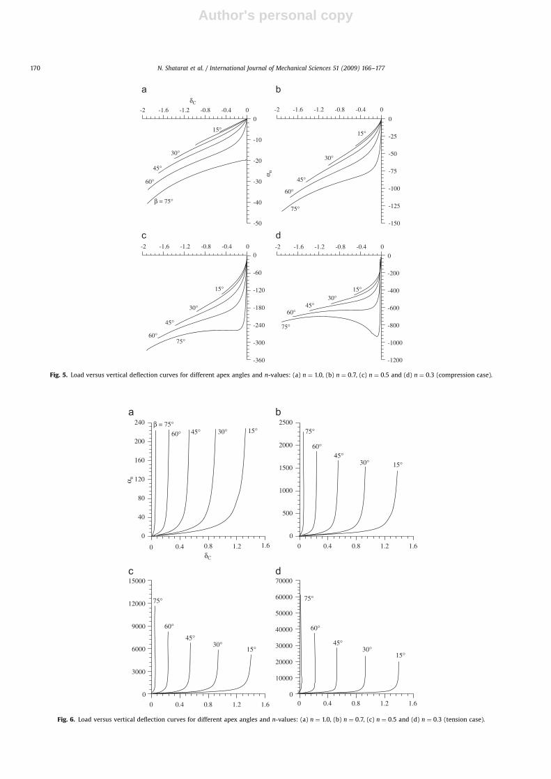
Fig. 7. Load versus relative horizontal displacement, dBD curves, for different apex angles and n-values: (a) n ¼ 1.0, (b) n ¼ 0.7, (c) n ¼ 0.5 and (d) n ¼ 0.3 (compression
case).
-1.60
40
80
120
160
200
240
-1.60
500
1000
1500
2000
2500
-2
0
3000
6000
9000
12000
15000
-2
0
10000
20000
30000
40000
50000
60000
70000
β = 75°60°45°30°15°
60°
45°30°15°
75°
60°
45°30°15°
60°
45°30°
15°
75°
75°
α n
δBD
-1.2 -0.8 -0.4 0 -1.2 -0.8 -0.4 0
-1.6 -1.2 -0.8 -0.4 0 -1.6 -1.2 -0.8 -0.4 0
Fig. 8. Load versus relative horizontal displacement, dBD curves, for different apex angles and n-values: (a) n ¼ 1.0, (b) n ¼ 0.7, (c) n ¼ 0.5 and (d) n ¼ 0.3 (tension case).
N. Shatarat et al. / International Journal of Mechanical Sciences 51 (2009) 166–177 171

Author's personal copyARTICLE IN PRESS
-400
30
60
90
120
150
-140
0
400
800
1200
1600
2000
-3600
2000
4000
6000
8000
-10000
6000
12000
18000
24000
β = 75° = 60° = 45° = 30° = 15° 75°
15° 15°
75°
15°
15°
75°
75°
αn
ΚN
L
-30 -20 -10 0 -105 -70 -35 0
-270 -180 -90 0 -750 -500 -250 0
Fig. 9. Nonlinear secant stiffness versus load parameter for different apex angles and n-values: (a) n ¼ 1.0, (b) n ¼ 0.7, (c) n ¼ 0.5 and (d) n ¼ 0.3 (compression case).
50
10
100
1000
10000
Log
(Κ
NL)
0
10
100
1000
10000
100000
1000000
0
100
1000
10000
100000
1000000
0
100
1000
10000
100000
1000000
10000000
β = 75°
60°
45°30°15°
60°45°
30°15°
75°
60°
45°30°
15°
60°45°
30°15°
75°
75°
αn
100 150 200 250 400 800 1200 1600 2000 2400
2000 4000 6000 8000 1000012000 20000 40000 60000 80000
Fig. 10. Nonlinear secant stiffness versus load parameter for different apex angles and n-values: (a) n ¼ 1.0, (b) n ¼ 0.7, (c) n ¼ 0.5 and (d) n ¼ 0.3 (tension case).
N. Shatarat et al. / International Journal of Mechanical Sciences 51 (2009) 166–177172
Author's personal copyARTICLE IN PRESS
x n
-1
-0.5
0
0.5
1
y n
α = −1.49α = −4.4α = −17.027
-1
-0.5
0
0.5
1α = −15.4α = −32.718α = −62.086
-1
-0.5
0
0.5
1α = −71.35α = −121.709α = −195.62
-1
-0.5
0
0.5
1 α = −310.72α = −425.525α = −580.205
Undeformed Shape
Fig. 11. Deformed shapes of the rhombus under compression and for an apex angle of 151 with different n-values: (a) n ¼ 1.0, (b) n ¼ 0.7, (c) n ¼ 0.5 and (d) n ¼ 0.3.
-1.5
-1
-0.5
0
0.5
1
y n
α = −8.19α = −15.32α = −47.988
-1.5
-1
-0.5
0
0.5
1
α = −51.598α = −78.645α = −208.357
-1.5
-1
-0.5
0
0.5
1
α = −171.651α = −228.476α = −548.51
-1
-1.5
-1
-0.5
0
0.5
1
α = −535.845α = −596.988α = −1380.285
-0.5 0 0.5 1
Fig. 12. Deformed shapes of the rhombus under compression and for an apex angle of 451 with different n-values: (a) n ¼ 1.0, (b) n ¼ 0.7, (c) n ¼ 0.5 and (d) n ¼ 0.3.
N. Shatarat et al. / International Journal of Mechanical Sciences 51 (2009) 166–177 173
Author's personal copy
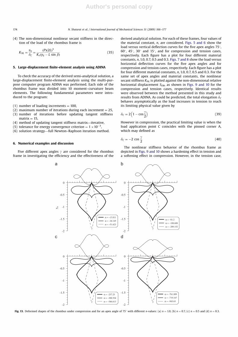
(4) The non-dimensional nonlinear secant stiffness in the direc-tion of the load of the rhombus frame is
KNL ¼an
dC¼
ðPÞð2LÞ3
KeðyE � L sin bÞ(35)
5. Large-displacement finite-element analysis using ADINA
To check the accuracy of the derived semi-analytical solution, alarge-displacement finite-element analysis using the multi-pur-pose computer program ADINA was performed. Each side of therhombus frame was divided into 10 moment–curvature beamelements. The following fundamental parameters were intro-duced to the program:
(1) number of loading increments ¼ 100,(2) maximum number of iterations during each increment ¼ 25,(3) number of iterations before updating tangent stiffness
matrix ¼ 15,(4) method of updating tangent stiffness matrix—iterative,(5) tolerance for energy convergence criterion ¼ 1�10�3,(6) solution strategy—full Newton–Raphson iteration method.
6. Numerical examples and discussion
Five different apex angles g are considered for the rhombusframe in investigating the efficiency and the effectiveness of the
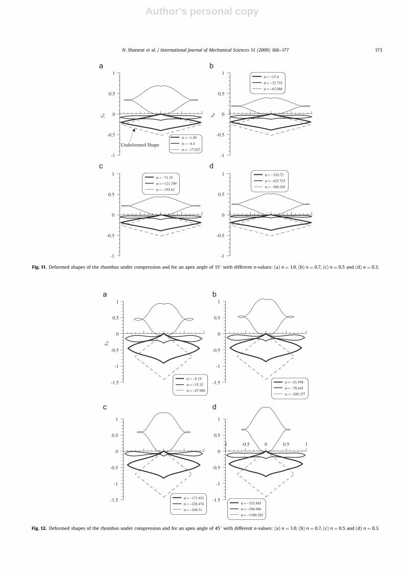
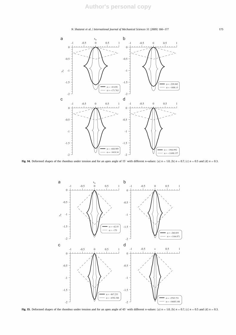
derived analytical solution. For each of these frames, four values ofthe material constant, n, are considered. Figs. 5 and 6 show theload versus vertical deflection curves for the five apex angles 751,601, 451, 301 and 151, and for compression and tension cases,respectively. Each figure has a plot for four different materialconstants, n, 1.0, 0.7, 0.5 and 0.3. Figs. 7 and 8 show the load versushorizontal deflection curves for the five apex angles and forcompression and tension cases, respectively. Each figure has a plotfor four different material constants, n, 1.0, 0.7, 0.5 and 0.3. For thesame set of apex angles and material constants, the nonlinearsecant stiffness KNL is plotted against the non-dimensional relativehorizontal displacement SDB, as shown in Figs. 9 and 10 for thecompression and tension cases, respectively. Identical resultswere observed between the method presented in this study andresults from ADINA. As could be predicted, the total elongation dC
behaves asymptotically as the load increases in tension to reachits limiting physical value given by
dC ¼ 2 1� cosg2
� �(39)
However in compression, the practical limiting value is when theload application point C coincides with the pinned corner A,which may defined as
dC ¼ �2 cosg2
(40)
The nonlinear stiffness behavior of the rhombus frame asdepicted in Figs. 9 and 10 shows a hardening effect in tension anda softening effect in compression. However, in the tension case,
ARTICLE IN PRESS
-2
-1.5
-1
-0.5
0
y n
α = −13.811α = −24.145α = −51.623
-2
-1.5
-1
-0.5
0
α = −81.2α = −108.608α = −209.152
-2
-1.5
-1
-0.5
0
α = −257.25α = −288.524α = −546.613
-2
-1.5
-1
-0.5
0
α = −761.809α = −719.167α = −943.63
Fig. 13. Deformed shapes of the rhombus under compression and for an apex angle of 751 with different n-values: (a) n ¼ 1.0, (b) n ¼ 0.7, (c) n ¼ 0.5 and (d) n ¼ 0.3.
N. Shatarat et al. / International Journal of Mechanical Sciences 51 (2009) 166–177174
Author's personal copyARTICLE IN PRESS
-1
-2
-1.5
-1
-0.5
0
y n
α = −43.658α = −171.763
-1
-2
-1.5
-1
-0.5
0
α = −228.842α = −1008.15
-1
-2
-1.5
-1
-0.5
0
α = −684.909α = −3418.34
-1
-2
-1.5
-1
-0.5
0
α = −1964.992α = −11698.157
xn
-0.5 0 0.5 1 -0.5 0 0.5 1
-0.5 0 0.5 1 -0.5 0 0.5 1
Fig. 14. Deformed shapes of the rhombus under tension and for an apex angle of 151 with different n-values: (a) n ¼ 1.0, (b) n ¼ 0.7, (c) n ¼ 0.5 and (d) n ¼ 0.3.
-1xn
-2
-1.5
-1
-0.5
0
y n
α = −42.55
α = −170
-1
-2
-1.5
-1
-0.5
0
α = −260.855
α = −1166.871
-1
-2
-1.5
-1
-0.5
0
α = −867.235
α = −4392.388
-1
-2
-1.5
-1
-0.5
0
α = −2765.751
α = −16685.108
-0.5 0 0.5 1 -0.5 0 0.5 1
-0.5 0 0.5 1 -0.5 0 0.5 1
Fig. 15. Deformed shapes of the rhombus under tension and for an apex angle of 451 with different n-values: (a) n ¼ 1.0, (b) n ¼ 0.7, (c) n ¼ 0.5 and (d) n ¼ 0.3.
N. Shatarat et al. / International Journal of Mechanical Sciences 51 (2009) 166–177 175
Author's personal copy
the rate of increase of the nonlinear stiffness with respect to theload increases as the material constant n decreases. For a givenmaterial constant and for different apex angles, this rate ofincrease is nearly constant for a good portion of the tensile load ascould be observed in Fig. 10. In the compression case, themagnitude of the compressive load is quite limited as comparedto the tensile load in the tension case.
The deformed shape of the rhombus frame is plotted for threevalues of the apex angle, 751, 451 and 151 and different loadingparameters. Figs. 11–13 show the deformed shapes for thecompression case and for four different material constants, n,1.0, 0.7, 0.5 and 0.3. Similarly, Figs. 14–16 show the deformedshapes for the tension load case. These figures demonstrate theability of the semi-analytical solution to predict extreme cases oflarge deflection for the rhombus frame. In addition, these figuresindicate that the frame exhibits a spring behavior with usefulapplications in fields such as compliant mechanisms, flexuralpivots, MEMS and others.
7. Conclusions
A semi-analytical solution has been derived for the springbehavior of a prismatic flexible rhombus frame made of a materialhaving a nonlinear stress–strain relationship of the Ludwick type.Different apex angles with four different material constants areconsidered along with a series of tension and compression loads.The spring behavior of the frame is presented by its load–deflec-tion curve and nonlinear secant stiffness. It is observed from theload–deflection curves that the frame has a hardening effect intension and a softening effect in compression for all apex angles.The nonlinear secant stiffness has a nearly constant rate ofincrease for a considerable region in the tension load zone. Whencompared with finite-element analysis, the semi-analytical solu-tion gave excellent agreement and predicted extreme cases oflarge deflection.
References
[1] Wang CY. Large deformations of a heavy cantilever. Quart Appl Math1991;39:261–73.
[2] Watson LT, Wang CY. Hanging an elastic ring. Int J Mech Sci 1981;23:161–7.[3] Wang CY, Watson LT. The elastic catenary. Int J Mech Sci 1982;24:349–57.[4] Navaee S, Elling RE. Equilibrium configurations of cantilever beam subjected
to inclined end loads. Trans ASME 1992;59:572–9.[5] Faulkner MG, Lipsett AW, Tam V. On the use of a segmental shooting
technique for multiple solutions of planar elastica problems. Comput MethAppl Mech Eng 1993;110:221–36.
[6] Ohtsuki A, Yasui T. Analysis of large deflections in cantilever beam underinclined tip load. Trans JSME 1993;60:2100–6.
[7] Chucheepsakul S, Buncharoen S, Wang CM. Large deflection of beams undermoment gradient. ASCE J Eng Mech 1994;120:1848.
[8] Wang CM, Lam KY, He XQ, Chucheepsakul S. Large deformation of an endsupported beam subjected to a point load. Int J Mech Non-Linear Mech1997;32:63–72.
[9] Golley BW. The solution of open and closed elasticas using intrinsiccoordinate finite elements. Comput Meth Appl Mech Eng 1997;146:127–34.
[10] Chucheepsakul S, Wang CM, He XQ, Monprapussorn T. Double curvaturebending of variable-arc-length elastica. J Appl Mech 1999;66:87–94.
[11] Lee BK, Oh SJ. Elastica and buckling load of simple tapered columns withconstant volume. Int J Solids Struct 2000;37:2507–18.
[12] Lee K. Post-buckling of uniform cantilever column under a combined load. IntJ Mech Non-Linear Mech 2001;36:813–6.
[13] Magnusson A, Ristinmaa M, Ljung C. Behavior of the extensible elasticacolumn. Int J Solids Struct 2001;38:8441–57.
[14] Madhusudan BP, Rajeev VR, Rao BN. Post-buckling of cantilever columnshaving variable cross-section under a combined load. Int J Non-Linear Mech2003;38:1513–22.
[15] Katsikadelis JT, Tsiatas GC. Large deflection analysis of beams with variablestiffness. Acta Mech 2003;164:1–13.
[16] Dado M, Al-Sadder S, Abuzeid O. Post-buckling behavior of two elasticacolumns linked with a rotational spring. Int J Non-Linear Mech 2004;39:1579–87.
[17] Oden JT, Childs SB. Finite deflections of a nonlinearly elastic bar. J Appl Mech1970;69:48–52.
[18] Parathep G, Varadan TK. The inelastic large deformation of beams. J ApplMech 1976;43:689–90.
[19] Monasa F. The effect of material nonlinearity on the bending of the elastica.In: Proceeding of the third engineering mechanical specialty conference,ASCE, 1979. p. 638–41.
[20] Lewis G, Monasa F. Large deflection of cantilever beams of nonlinearmaterials. Int J Comput Struct 1981;14(5–6):357–60.
ARTICLE IN PRESS
-1
-2
-1.5
-1
-0.5
0
α = −13.906α = −169.151
-1
-2
-1.5
-1
-0.5
0
α = −131.574α = −1616.833
-1
-2
-1.5
-1
-0.5
0
α = −577.91α = −7590.442
-1
-2
-1.5
-1
-0.5
0
α = −2402.854α = −35957.286
y n
xn
-0.5 0 0.5 1 -0.5 0 0.5 1
-0.5 0 0.5 1 -0.5 0 0.5 1
Fig. 16. Deformed shapes of the rhombus under tension and for an apex angle of 751 with different n-values: (a) n ¼ 1.0, (b) n ¼ 0.7, (c) n ¼ 0.5 and (d) n ¼ 0.3.
N. Shatarat et al. / International Journal of Mechanical Sciences 51 (2009) 166–177176

Author's personal copy
[21] Yu TX, Johnson W. The plastica: the large elastic–plastic deflection of a strut.Int J Non-Linear Mech 1982;17(3):195–209.
[22] Wang CY. A critical review of the heavy elastica. Int J Mech Sci 1986;28(8):549–59.
[23] Lewis G, Mazilu P, Monasa F. A variational approach for the deflections andstability behavior of post-buckled elastic–plastic slender struts. Int J Non-Linear Mech 1987;22(5):373–85.
[24] Luan F, Yu TX. An analysis of the large deflection of an elastic–plasticcantilever subjected to an inclined concentrated force. Appl Math Mech (EnglEd) 1991;12:547–56.
[25] Fertis DG, Lee CT. Inelastic analysis of flexible bars using simplified nonlinearequivalent systems. Comput Struct 1991;41:947–58.
[26] Fertis DG. Nonlinear mechanics. 2nd ed. Boca Raton, FL: CRC Press; 1999.[27] Lee K. Large deflections of cantilever beams of nonlinear elastic material
under a combined loading. Int J Non-Linear Mech 2002;37:439–43.[28] Huang X, Wang B, Lu G, Yu TX. Large deflection of elastoplastic, non-linear strain-
hardening cantilevers. Proc Inst Mech Eng Part C J Mech Eng Sci 2002;216:433–46.[29] Al-Sadder S, Shatarat N. A proposed technique for large deflection analysis of
cantilever beams composed of two nonlinear elastic materials subjected to aninclined tip concentrated force. Adv Struct Eng 2007;10(3).
[30] Jenkins JA, Seitz TB, Przemieniecki JS. Large deflections of diamond-shapedframes. Int J Solids Struct 1966;2:591–603.
[31] Theocaris PS, Panayotounakos DE. Closed-form solutions for strongly non-linear differential equations describing the elastica of straight bars: applica-tions to frames. Res Mech 1988;24:35–46.
[32] Thacker WI, Wang CY, Watson LT. The nonlinear stability of a heavy rigidplate supported by flexible columns. Int J Solids Structures 1993;30:3443–9.
[33] Wang CY. Analysis of nonlinear deformations of a triangular frame. MechStruct Mach 2000;28:237–43.
[34] Ohtsukia A, Ellyin F. Large deformation analysis of a square frame with rigidjoints. Int J Thin-Walled Struct 2000;38:79–91.
[35] Dado M, Al-Sadder S. The elastic spring behavior of a rhombus frameconstructed from non-prismatic beams under large deflection. Int J Mech Sci2006;48:958–68.
[36] Nielson AJ, Howell LL. An investigation of compliant micro-half-pantographsusing the pseudo rigid body model. Mech Struct Mach 2001;29(3):317–30.
[37] ADINA. ADINA user interface (AUI) users guide. Watertown, MA: ADINA R andD, Inc.; 2002.
ARTICLE IN PRESS
N. Shatarat et al. / International Journal of Mechanical Sciences 51 (2009) 166–177 177


![Author's personal copy - · PDF fileAuthor's personal copy 68 A.S. Kim, Y. Liu / Journal of Membrane Science 323 (2008) 67 76 mechanisms were separately investigated [15,16] , Sethi](https://img.pdfslide.us/doc/110x75/5a792ee37f8b9a07628d2555/authors-personal-copy-s-personal-copy-68-as-kim-y-liu-journal-of-membrane.jpg)