Embed Size (px)
Citation preview

Title Distributed multimedia systems
Author(s) Li, VOK; Liao, Wanjiun
Citation Institute of Electrical and Electronics Engineers Proceedings,1997, v. 85 n. 7, p. 1063-1108
Issued Date 1997
URL http://hdl.handle.net/10722/42773
Rights
©1997 IEEE. Personal use of this material is permitted. However,permission to reprint/republish this material for advertising orpromotional purposes or for creating new collective works forresale or redistribution to servers or lists, or to reuse anycopyrighted component of this work in other works must beobtained from the IEEE.; This work is licensed under a CreativeCommons Attribution-NonCommercial-NoDerivatives 4.0International License.

Distributed Multimedia Systems
VICTOR O. K. LI, FELLOW, IEEE, AND WANJIUN LIAO, STUDENT MEMBER, IEEE
A distributed multimedia system (DMS) is an integrated com-munication, computing, and information system that enables theprocessing, management, delivery, and presentation of synchro-nized multimedia information with quality-of-service guarantees.Multimedia information may include discrete media data, such astext, data, and images, and continuous media data, such as videoand audio. Such a system enhances human communications byexploiting both visual and aural senses and provides the ultimateflexibility in work and entertainment, allowing one to collaboratewith remote participants, view movies on demand, access on-linedigital libraries from the desktop, and so forth. In this paper, wepresent a technical survey of a DMS. We give an overview ofdistributed multimedia systems, examine the fundamental conceptof digital media, identify the applications, and survey the importantenabling technologies.
Keywords—Digital media, distributed systems, hypermedia, in-teractive TV, multimedia, multimedia communications, multimediasystems, video conferencing.
NOMENCLATURE
AAL ATM adaptation layer.A/D Analog to digital.ADPCM Adaptive differential pulse code modula-
tion.ADSL Asynchronous digital subscriber loop.ANSI American National Standard Institute.API Application-independent program inter-
face.ATM Asynchronous transfer mode.B-ISDN Broad-band integrated services digital net-
work.BLOB Binary large object.CATV Community antenna TV.
Manuscript received June 5, 1996; revised April 5, 1997. This work issupported in part by the U.S. Department of Defense Focused ResearchInitiative Program under Grant F49620-95-1-0531 and in part by thePacific Bell External Technology Program.
V. O. K. Li was with the University of Southern California, Communica-tion Sciences Institute, Department of Electrical Engineering, Los Angeles,CA 90089-2565 USA. He is now with the Department of Electrical andElectronic Engineering, University of Hong Kong, China.
W. Liao was with the University of Southern California, CommunicationSciences Institute, Department of Electrical Engineering, Los Angeles,CA 90089-2565 USA. She is now with the Department of ElectricalEngineering, National Taiwan University, Taipei, Taiwan.
Publisher Item Identifier S 0018-9219(97)05311-5.
CBR Constant bit rate.CCITT Comite Consultatif Internationale de
Telegraphique et Telephonique.CD-ROM Compact disc-read only memory.CGI Common gateway interface.CIF Common intermediate format.CPU Central processing unit.CS Convergence sublayer.D/A Digital to analog.DAB Digital audio broadcast.DBS Direct broadcast satellite.DCT Discrete cosine transform.DDL Data definition language.DHRM Dexter hypertext reference model.DML Data manipulation language.DMS Distributed multimedia systems.DPCM Differential pulse code modulation.DTD Document type declaration.DVC Digital video cassette.DVD Digital video disc.DVI Digital video interactive.EDF Earliest deadline first.ETSI European Telecommunication Standard
Institute.FM Frequency modulation.GDSS Group-decision support system.GSS Grouped sweeping scheduling.HAM Hypertext abstract machine.HDM Hypermedia design model.HDTV High-definition TV.HFC Hybrid fiber coax.HTML Hypertext markup language.HTTP Hypertext transport protocol.IETF Internet Engineering Task Force.IMA Interactive Multimedia Association.ISDN Integrated services digital network.ISO International Standard Organization.ITU-T International Telecommunications Union-
Telecommunication.ITV Interactive television.JPEG Joint Photographic Experts Group.LAN Local area network.LMDS Local multipoint distribution system.
0018–9219/97$10.00 1997 IEEE
PROCEEDINGS OF THE IEEE, VOL. 85, NO. 7, JULY 1997 1063

MAN Metropolitan area network.MBone Multicast backbone.MHEG Multimedia/Hypermedia Expert Group.MIME Multipurpose Internet mail extensions.MMDS Multichannel multipoint distribution sys-
tem.MPEG Motion Pictures Experts Group.MTP Multicast transport protocol.NTP Network time protocol.NTSC National Television Systems Committee.OAM&P Operation, administration, maintenance,
and provision.ODA Office document architecture.OS Operating system.OSPF Open shortest path first.PAL Phase alternation line.PC Personal computer.PSTN Public switched telephone network.QCIF Quarter-CIF.QoS Quality of service.RCAP Real-time channel administration proto-
col.RSVP Reservation protocol.RTP Real-time transport protocol.RTCP RTP control protocol.SAR Segmentation and reassembly.SECAM Sequential couleur avec memoire.SCSI Small computer system interface.SGML Standard generalized markup language.SMDS Switched multimegabit data service.SMPT Simple mail transfer protocol.SONET Synchronous optical network.ST-II Stream protocol version 2.TCP/IP Transport control protocol/Internet proto-
col.TDMA Time division multiple access.UDP User data protocol.VBR Variable bit rate.VC Virtual channel.VCI Virtual channel identifier.VOD Video on demand.VP Virtual path.VPI Virtual path identifier.WAN Wide area network.WWW (W3) World Wide Web.
I. INTRODUCTION
DMS’s will revolutionize current life-styles, especiallythose aspects associated with human communications. Suchsystems will create an electronic world in which people areable to shop, work, or learn at home, watch video pro-grams on demand, access on-line digital libraries from thedesktop, and so forth. Technological advances in comput-ers, high-speed networks, data compression, and consumerelectronics—coupled with the availability of multimediaresources, mechanisms, and manipulation functions, thedevelopment of the relevant standards, and the convergency
of the computer, telecommunication, and cable televisionindustries—are accelerating the realization of such systems.
A multimedia system is an interactive digital multimediasystem. It seamlessly integrates multimedia information viacomputers and allows users to interact with such informa-tion according to their preferences. Multimedia informationincludes video, audio, and other continuous media in addi-tion to discrete media such as text, data, and still images.Discrete media data are often displayed as one presentationunit, while continuous media data are composed of aseries of consecutive units of equal presentation duration[1]. The ability to accommodate continuous as well asdiscrete media in an integrated system is the distinguishingfeature of multimedia systems. A DMS augments stand-alone multimedia systems with a real-time network; realtime here refers to timely delivery with acceptable qual-ity. According to application needs, the system providesservices in an interactive (e.g., VOD) or broadcasting(e.g., video conferencing) mode and in a timely (e.g.,video browsing) or messaging (e.g., multimedia e-mail)manner. An example of a DMS is a number of multimediaPC’s and/or workstations interconnected with continuousmedia servers via the Internet that allow users to retrieve,browse, and manipulate video or audio. Such networkedmultimedia systems not only dramatically enhance theexisting CD-ROM-based multimedia applications but alsoencourage newly emerging broad-band applications at theexpense of more complexity due to the requirement ofQoS guarantees. These include constraints on bit errorrates, packet loss probabilities, and delivery delays re-quired in a traditional point-to-point information deliverysystem, plus additional constraints introduced due to theorchestration of distributed media in a DMS, such asthe synchronization among multiple media streams fromdistributed sources to achieve a meaningful presentation.We formally define a DMS as an integrated communi-cation, computing, and information system that enablesthe processing, management, delivery, and presentation ofsynchronized multimedia information with QoS guaran-tees.
Fig. 1 summarizes a DMS. The inputs of the systemconsist of the important factors that drive a DMS fromconcept to reality, and the outputs consist of a wide rangeof distributed multimedia applications. The system inputscan be divided into three orthogonal dimensions. The inputsfrom the left-hand side are the major contribution indus-tries, including the computer, telecommunication, cable TV,entertainment, and consumer electronics industries. Theinputs from the right-hand side are the important issuesin the development of a DMS, including the technical,standardization, regulation, copyright, market, and socialand human factors. The inputs from the top are a collectionof the enabling technologies of the information subsystem(for storage), the communication subsystem (for transmis-sion), and the computing subsystem (for processing). Theinformation subsystem consists of the multimedia servers,information archives, and multimedia database systems. Itstores and retrieves multimedia information, serves a large
1064 PROCEEDINGS OF THE IEEE, VOL. 85, NO. 7, JULY 1997

Fig. 1. A distributed multimedia system.
number of simultaneous user requests with QoS guaran-tees, and manages the data for consistency, security, andreliability. The communication subsystem consists of thetransmission medium and transport protocols. It connectsthe users with distributed multimedia resources and deliversmultimedia materials with QoS guarantees, such as real-time delivery for video or audio data and error-free deliveryfor text data. The computing subsystem consists of amultimedia platform (ranging from a high-end graphicsworkstation to a multimedia PC equipped with a CD-ROMdrive, speaker, sound card, and video card), OS, presen-tation and authoring1 tools, and multimedia manipulationsoftware. It allows users to manipulate the multimediadata. The outputs of the system can be broadly classi-fied2 into three different types of distributed multimediaapplications: ITV, telecooperation, and hypermedia. ITVallows subscribers to access video programs at the time theychoose and to interact with them. Services include homeshopping, interactive video games,3 financial transactions,VOD, news on demand, and CD on demand. Telecooper-ation overcomes time and location restrictions and allowsremote participants to join a group activity. Services includeremote learning, telecommuting, teleservicing, teleopera-tion, multimedia e-mail, videophone, desktop conferencing,electronic meeting rooms, joint editing, and group drawing.A hypermedia document is a multimedia document with“links” to other multimedia documents that allows users tobrowse multimedia information in a nonsequential manner.Services include digital libraries, electronic encyclopedias,multimedia magazines, multimedia documents, information
1An authoring tool is a specialized software that allows a producer ordesigner to design and assemble multimedia elements for a multimediapresentation, either through scripting languages (such as Script-X, PerlScript, and JavaScript) or menu- and icon-based graphical interfaces (suchas Director, Hypercard, and Apple Media Tool).
2Our criteria for classification is described in Section III.3Interactive video games can also be classified as a hypermedia appli-
cation.
kiosks, computer-aided learning tools, and WWW (or W3)surfing.
The main features of a DMS are summarized as follows[2]–[10].
1) Technology integration:integrates information, com-munication, and computing systems to form a unifieddigital processing environment.
2) Multimedia integration:accommodates discrete dataas well as continuous data in an integrated environ-ment.
3) Real-time performance:requires the storage systems,processing systems, and transmission systems to havereal-time performance. Hence, huge storage volume,high I/O rate, high network transmission rate, andhigh CPU processing rate are required.
4) System-wide QoS support:supports diverse QoS re-quirements on an end-to-end basis along the data pathfrom the sender, through the transport network, andto the receiver.
5) Interactivity: requires duplex communication betweenthe user and the system and allows each user tocontrol the information.
6) Multimedia synchronization support:preserves theplayback continuity of media frames within a singlecontinuous media stream and the temporal relation-ships among multiple related data objects.
7) Standardization support:allows interoperability de-spite heterogeneity in the information content, pre-sentation format, user interfaces, network protocols,and consumer electronics.
The rest of this paper is organized as follows. Sec-tion II overviews digital media fundamentals. Section IIIpresents three important types of distributed multimedia ap-plications, including ITV, telecooperation, and hypermedia
LI AND LIAO: DISTRIBUTED MULTIMEDIA SYSTEMS 1065

systems. Section IV addresses the technical aspects of theinformation, communication, and computing subsystems.Section V presents our conclusions.
II. DIGITAL MEDIA FUNDAMENTALS
Just as the printing press, telegraph, telephone, and massmedia have revolutionized human communications, theemerging digital media are expected to spawn anotherrevolution in communications.
Electronic media and transducers are essential parts ofmultimedia presentation. A medium is something throughwhich information travels. For example, natural media canbe air, water, and space. Information travels in naturalmedia in the form of waves, such as light waves and soundwaves. Electronic media are distinguished from naturalmedia in their abilities to record, duplicate, manipulate,and synthesize information [11]. Examples of electronicmedia include computer disks, CD-ROM’s, videotapes,and cables. The transducer is a device capable of chang-ing signals from one form to another. Microphones andvideo cameras are examples of transducers that convertsound waves and light intensity, respectively, into electricalsignals. Conversely, loudspeakers and monitors convertelectrical signals into sound and light, respectively.
Information can be represented as analog signals ordigital signals. Analog signals exhibit a continuous toneof smooth fluctuations, while digital signals are composedof discrete values represented by numbers. The transfor-mation between analog and digital signals is achieved byA/D conversions and D/A conversions. A/D conversiontransforms an analog input (such as voltage) into a seriesof numeric representation by digitization. Digitization iscomposed of sampling and quantizing. Sampling takessnapshots of the analog waveform at certain points intime, and the sampling rate determines how often theanalog signal is digitized. According to the Nyquist the-orem, the sampling rate must be at least twice the highestfrequency component of the analog waveform to repro-duce the signal optimally [12]. Quantization determinesthe digital measured value of the analog waveform atthe sampling time. The larger the range of numbers usedfor the quantization, the more gradations of the digitallysampled waveform can be represented. Fig. 2 illustratessampling and quantization. In Fig. 2(a), the analog wave-form is sampled at periodic points in time. The sampledvalues are then represented by the closest quantizationlevels. The difference between the value of the closestquantization level and the real analog value is known asthe quantization error, or quantization noise. In Fig. 2(b),a 2-b binary number is used to represent the quantiza-tion level, resulting in four possible levels. In Fig. 2(c),three bits are used, allowing eight quantization levels. Asexpected, quantization error increases as the number ofbits used to represent a sample decreases. D/A conver-sion is the reverse process of A/D conversion. It turnsa sequence of discrete numbers back into the continuousanalog signal. Fig. 3 shows the role of A/D and D/A
converters in the acquisition and playback of digital mediasystems.
Digital media take advantage of advances in computer-processing techniques and inherit their strengths from dig-ital signals. The distinguishing features that make themsuperior to the analog media are listed as follows.
1) Robustness:the quality of digital media will notdegrade as copies are made. They are more stableand more immune to the noises and errors that occurduring processing and transmission. Analog signals,on the other hand, suffer from signal path attenuationand generation loss (as copies are made) and areinfluenced by the characteristics of the medium itself.
2) Seamless integration:the integration of different me-dia via digital storage, processing, and transmis-sion technologies, regardless of the particular mediaproperties. Therefore, digital media eliminate devicedependency in an integrated environment and alloweasy data composition and nonlinear editing.
3) Reusability and interchangeability:with the develop-ment of standards for the common exchange formats,digital media have greater potential to be reused andshared by multiple users.
4) Ease of distribution potential:thousands of copiesmay be distributed electronically by a simple com-mand.
A. Digital Image
Digital images are captured directly by a digital cameraor indirectly by scanning a photograph with a scanner. Theyare usually compressed before being stored or transmittedand are displayed on the screen or printed.
1) Image Display: Digital images are composed of a col-lection of pixels that are arranged as a two-dimensionalmatrix. This two-dimensional (or spatial) representation iscalled the image resolution. As shown in Fig. 4, each pixelconsists of three components: the red the greenand the blue . On a screen, each component of a pixelcorresponds to a phosphor. A phosphor glows when excitedby an electron gun. Various combinations of differentintensities produce different colors. The number of bits torepresent a pixel is called the color depth, which decidesthe actual number of colors available to represent a pixel.Color depth in turn is determined by the size of the videobuffer in the display circuitry. For example, a screen witha 640-by-480 resolution and with 24-b color (i.e., eightbits each for the and components) displays 640pixels horizontally and 480 vertically, and each pixel canbe represented by selecting from more than 2 16.7million) different colors.
2) Digital Image Data: The resolution and color depthdetermine the presentation quality and the size of imagestorage. The more pixels and the more colors, the betterthe quality and the larger the volume. For example, a 640-by-480 image with 24-b color requires 640480 24 b
7.4 Mb of storage. To reduce the storage requirement,
1066 PROCEEDINGS OF THE IEEE, VOL. 85, NO. 7, JULY 1997

(a)
(b)
(c)
Fig. 2. (a) Sampling. (b) Quantization with four levels. (c) Quantization with eight levels.
three different approaches can be used: indexed color, colorsubsampling, and spatial reduction.
a) Indexed color: This approach reduces the storagesize by using a limited number of bits with a color look-uptable (or color palette) to represent a pixel. For example,a 256-color palette would limit each pixel value to an 8-b number. The value associated with the pixel, insteadof direct color information, represents the index of thecolor table. This approach allows each of the 256 entriesin the color table to reference a color of higher depth, a12-b, 16-b, or 24-b value depending on the system, butlimits the maximum number of different colors that canbe displayed simultaneously to 256. Dithering, a techniquetaking advantage of the fact that the human brain perceivesthe median color when two different colors are adjacentto one another, can be applied to create additional colorsby blending colors from the palette. Thus, with paletteoptimization and color dithering, the range of the overallcolor available is still considerable, and the storage size isreduced.
b) Color subsampling:Humans perceive color as thebrightness, the hue, and the saturation rather than ascomponents. Human vision is more sensitive to variation
in the luminance (or brightness) than in the chrominance(or color difference). To take advantage of such deficien-cies in the human eye, light can be separated into theluminance and chrominance components instead of the
components. For example, the color spaceseparates luminance from chrominance via the followinglinear transformation from the system
where is the luminance component and are thechrominance components.
The color subsampling approach shrinks the file sizeby downsampling the chrominance component (i.e., usingless bits to represent the chrominance component) whileleaving the luminance component unchanged. There are twodifferent approaches to compressing color information.
1) Use less, say, half the number of bits used for,to represent and each. For example, 24-b coloruses eight bits each for the and components.
LI AND LIAO: DISTRIBUTED MULTIMEDIA SYSTEMS 1067

Fig. 3. A/D and D/A converters.
Fig. 4. A pixel composition.
When applying color subsampling, eight bits are usedfor and four bits each are used for and .
2) Alternately drop either chrominance component (i.e.,. For example, process the
component of while discarding the component of, then process the component ofwhile discardingand alternately discarding the and compo-
nents. Each 24-b sample can thus be reduced to 16 b:eight bits for and eight bits for either or .
c) Spatial reduction:This approach, also known asdata compression, reduces the size by throwing away thespatial redundancy within the images. Data compressionwill be described in detail in Section IV-B.
B. Digital Video
Video4 is composed of a series of still image frames andproduces the illusion of movement by quickly displayingframes one after another. The human vision system accepts
4Television and video are usually distinguished. Television is oftenassociated with the concept of broadcast or cable delivery of programs,whereas video allows more user interactivity, such as recording, editing,and viewing at a user-selected time. In this paper, we consider video withthe broader meaning of motion pictures, including television.
anything above 20 frames per second (fps) as smoothmotion.
1) Video Display: To paint an entire video image on amonitor, an electron gun illuminates every pixel as itsweeps across the screen from left to right and from topto bottom. This is called raster scanning. A completeline traveled by the electron gun from left to right iscalled a scanline. If the electron beams travel the scanlinessequentially from top to bottom, as shown in Fig. 5(a), it iscalled a progressive scan. If the electron beams travel theodd scanlines in one pass and the even scanlines in the next,it is called an interlaced scan, as shown in Fig. 5(b). For theinterlaced scan, each pass is called a field, and two completefields comprise a full display screen. When the electronbeam travels to the bottom scanline, it retraces back to thetop. The time of moving the electron gun from the bottomto the top is called the vertical blanking interval, while thetime from the right of one scanline to the left of the nextis the horizontal blanking interval. The vertical blankingintervals are often used to embed other signals, such assynchronization information, in broadcast television (TV)systems.
Two major technologies are adopted for video display:TV and computer monitors.
a) TV monitor: The input signals to TV are composite(to be described below). The TV monitor is an interlacedmonitor. The refresh rate is 60 fields per second (or 30fps).5 It uses the persistence of human vision as well asthe persistence of the phosphors to reduce the refresh rate.Thus, a TV monitor costs less but flickers often due tothe lower refresh rate. Video images on a TV monitorare overscanned, with the image area extending beyond
5The actual refresh rate depends on the type of TV system. For example,the rate for the NTSC TV system is 29.97 fps.
1068 PROCEEDINGS OF THE IEEE, VOL. 85, NO. 7, JULY 1997

Table 1 Comparison of the Three Analog TV Signal Standards
(a) (b)
Fig. 5. (a) Progressive scan. (b) Interlaced scan.
the physical viewing area of the monitor. The aspect ratioof TV, which is the ratio of the horizontal to the verticaldimensions, is 4 : 3.
b) Computer monitor:The input signals to a computermonitor are components. The computer monitor isa noninterlaced monitor. The refresh rate is 60 fps. Thevideo images are underscanned on the computer monitor,with the image area smaller than the physical viewing area,and therefore there is a black border around the image. Theaspect ratio of a computer monitor is also 4 : 3
2) Analog Versus Digital Video Signals:For both analogand digital videos, there are two different types of videosignals for storage and transmission.
1) A composite signal combines the luminanceandchrominance into a single stream to be stored andtransmitted. Examples of analog composites includebroadcast TV signals and VHS; examples of digitalcomposites include the D-2 and D-3 formats.
2) A component signal separates the video into lumi-nance and chrominance streams. There are twovariations of component signals: the componentand the component. The component usestwo separate channels to transportand informa-tion, whereas the component uses three chan-nels to carry and colors. Component videosignals have better quality than composite video.Examples of analog components include Hi8 (component) and Beta SP ( component), andthose of digital components include the D-1, D-4,and D-5 formats.
a) Analog signal: The video waveform actually rep-resents three signals at once: luminance, chrominance,and synchronization information. Three different types ofanalog video are used for TV broadcast [13], [14].
1) NTSC:provides an interlaced frame rate (or displayrate) of 29.97 fps with 525 lines, where 41 lines arereserved for the vertical blanking interval to yield484 lines of visual resolution. The luminance signalis called the signal. The chrominance signal isamplitude modulated onto the color subcarrier at twodifferent phases: the (in-phase) value at 0and the
(quadrature) value at 90.
2) PAL: offers an interlaced frame rate of 25 fps with 625scanlines. It provides more bandwidth for chromi-nance modulation, yielding better color resolution.The composite PAL signal operates on thecolor space, where is the luminance componentand ( ) are the chrominance components.
3) SECAM: uses the same resolution and interlacedframe rate as PAL but uses FM to encode the chromi-nance signal. It also has better color resolution thanNTSC.
The three video signals use the same bandwidth but adifferent number of scanlines and different refresh rates.Compared to NTSC, PAL and SECAM have better resolu-tion but lower refresh rates and hence more flicker. Table 1shows the comparison between these three video formats.
b) Digital signal: Digital video inherits the advantagesof digital signals as described earlier. The biggest chal-lenges posed by digital video are the massive volume ofdata involved and the need to meet the real-time constraintson retrieval, delivery, and display. The solution entails thefollowing.
1) Compromise in the presentation quality:instead ofvideo with full frame (i.e., images filling the completescreen), full fidelity (i.e., millions of colors at screenresolution), and full motion (i.e., 30 fps), one mayreduce the image size, use less bits to represent colors,or reduce the frame rate. (For a frame rate less than16 fps, the illusion of motion is replaced by theperception of a series of frames.)
2) Video compression:To reduce the massive volumeof digital video data, compression techniques withhigh compression ratios are required. In addition tothrowing away the spatial and color similarities of in-dividual images, the temporal redundancies betweenadjacent video frames are eliminated.
C. Digital Audio
1) Audio Perception:Sound waves generate air pressureoscillations that stimulate the human auditory system. Thehuman ear is an example of a transducer. It transformssound waves to signals recognizable by brain neurons. As
LI AND LIAO: DISTRIBUTED MULTIMEDIA SYSTEMS 1069

Fig. 6. The block diagram of digital audio processing.
with other audio transducers, two important considerationsare frequency response and dynamic range.
1) Frequency response:refers to the range of frequen-cies that a medium can reproduce accurately. Thefrequency range of human hearing is between 20 Hzand 20 kHz, and humans are especially sensitive tolow frequencies of 3–4 kHz.
2) Dynamic range:describes the spectrum of the softestto the loudest sound-amplitude levels that a mediumcan reproduce. Human hearing can accommodate adynamic range over a factor of millions, and soundamplitudes are perceived in logarithmic ratio ratherthan linearly. To compare two signals with amplitudes
and , the unit of decibel (dB) is used, defined as20 dB. Humans perceive sounds over theentire range of 120 dB, the upper limit of which willbe painful to humans.
Sound waves are characterized in terms of frequency(Hz), amplitude (dB), and phase (degree), whereas frequen-cies and amplitudes are perceived as pitch and loudness,respectively. Pure tone is a sine wave. Sound waves areadditive, and sounds in general are represented by a sum ofsine waves. Phase refers to the relative delay between twowaveforms, and distortion can result from phase shifts.
2) Digital Audio Data: Digital audio systems are de-signed to make use of the range of human hearing. Thefrequency response of a digital audio system is determinedby the sampling rate, which in turn is determined by theNyquist theorem. For example, the sampling rate of CD-quality audio is 44.1 kHz (which can accommodate thehighest frequency of human hearing, namely, 20 kHz),while telephone-quality sound adopts an 8-kHz samplingrate (which can accommodate the most sensitive frequencyof human hearing, up to 4 kHz). Digital audio aliasingis introduced when one attempts to record frequenciesthat exceed half the sampling rate. A solution is to usea low-pass filter to eliminate frequencies higher than the
Nyquist rate. The quantization interval, or the differencein value between two adjacent quantization levels, is afunction of the number of bits per sample and determinesthe dynamic range. One bit yields 6 dB of dynamic range.For example, 16-b audio contributes 96 dB of the dynamicrange found in CD-grade audio, nearly the dynamic rangeof human hearing. The quantized samples can be encodedin various formats, such as pulse code modulation (PCM),to be stored or transmitted. Quantization noise occurs whenthe bit number is too small. Dithering,6 which adds whitenoise to the input analog signals, may be used to reducequantization noise [12]. In addition, a low-pass filter canbe employed prior to the D/A stage to smooth the stair-stepeffect resulting from the combination of a low samplingrate and quantization. Fig. 6 summarizes the basic steps toprocess digital audio signals.
The quality of digital audio is characterized by thesampling rate, the quantization interval, and the numberof channels (e.g., one channel for mono systems, two forstereo systems, and 5.1 for Dolby surround-sound systems).The higher the sampling rate, the more bits per sample, andthe more channels, the higher the quality of the digital audioand the higher the storage and bandwidth requirements.For example, a 44.1-kHz sampling rate, 16-b quantization,and stereo audio reception produce CD-quality audio butrequire a bandwidth of 44 100 16 2 1.4 Mb/s.Telephone-quality audio, with a sampling rate of 8 kHz,8-b quantization, and mono audio reception, needs onlya data throughput of 8000 8 1 64 Kb/s. Again,digital audio compression or a compromise in quality canbe applied to reduce the file size.
III. D ISTRIBUTED MULTIMEDIA APPLICATIONS
Multimedia integration and real-time networking createa wide range of opportunities for multimedia applications.According to the different requirements imposed upon the
6Note that dithering here is different from the concept of ditheringdescribed in Section II-A.
1070 PROCEEDINGS OF THE IEEE, VOL. 85, NO. 7, JULY 1997

Fig. 7. A VOD system.
information, communication, and computing subsystems,distributed multimedia applications may be broadly classi-fied into three types: ITV, telecooperation, and hypermedia.ITV requires a very high transmission rate and stringentQoS guarantees. It is therefore difficult to provide suchbroad-band services over a low-speed network, such asthe current Internet, due to its low bandwidth and best-effort-only services. ITV typically demands point-to-point,switched connections as well as good customer servicesand excellent management for information sharing, billing,and security. Bandwidth requirement is asymmetric in thatthe bandwidth of the downstream channel that carries videoprograms from the server to the user is much higher thanthat of the upstream channel from the user to the server.In addition, the equipment on the customer’s premises,such as a TV with a box on top, is much less pow-erful than the equipment used in telecooperation, suchas video conferencing. Telecooperation requires multicast,multipoint, and multiservice network support for groupdistribution. In contrast to the strict requirement on thevideo quality of ITV, telecooperation, such as videophoneand desktop conferencing, allows lower picture qualityand therefore has a lower bandwidth requirement. It ispossible to provide such services with the developmentof real-time transport protocols over the Internet. As withhypermedia applications, telecooperation requires powerfulmultimedia database systems rather than just continuousmedia servers, with the support of visual query and content-based indexing and retrieval. Hypermedia applications areretrieval services and require point- or multipoint-to-pointand switched services. They also require friendly userinterfaces and powerful authoring and presentation tools.
A. Interactive TV
An important ITV service is VOD. VOD provides elec-tronic video-rental services over the broad-band network
[15]. Fig. 7 shows an example of a VOD system. Customersare allowed to select programs from remote massive videoarchives, view at the time they wish without leaving thecomfort of their homes, and interact with the programsvia VCR-like functions, such as fast-forward and rewind[16]–[22]. A VOD system that satisfies all of these require-ments (any video, any time, any VCR-like user interaction)is called a true VOD system and is said to provide trueVOD services; otherwise, it is called a near VOD system.
To be commercially viable, VOD service must be pricedcompetitively with existing video rental services (the localvideo rental store). One way to allow true VOD services isto have a dedicated video stream for each customer. Thisis not only expensive but is wasteful of system resourcesbecause if multiple users are viewing the same video, thesystem has to deliver multiple identical copies at the sametime. To reduce this cost, batching may be used. Thisallows multiple users accessing the same video to be servedby the same video stream. Batching increases the systemcapability in terms of the number of customers the systemcan support. However, it does complicate the provision ofuser interactions. In staggered VOD, for example, multipleidentical copies (streams) of the same video program arebroadcast at staggered times (e.g., every five minutes).A user will be served by one of the streams, and userinteractions are simulated by jumping to a different stream.Not all user interactions can be simulated in this fashion,however, and even for those that can be simulated, theeffect is not exactly what the user requires. For example,one cannot issue fast-forward because there is no streamin the fast-forward mode. Also, one may pause for 5,10, 15, etc. minutes but not for seven minutes becausethere is no stream that is offset in time by seven minutesfrom the original stream. An innovative protocol calledthe Split-and-Merge (SAM) [23] has been proposed toprovide true VOD services while fully exploiting the benefit
LI AND LIAO: DISTRIBUTED MULTIMEDIA SYSTEMS 1071
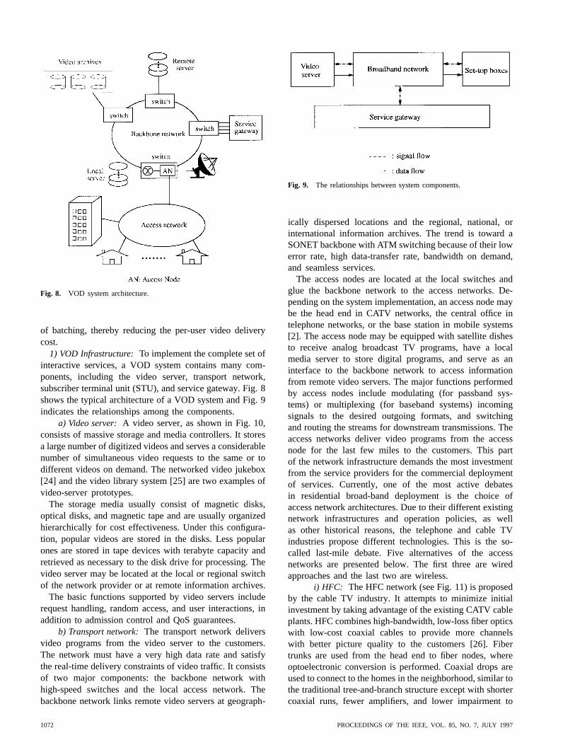
Fig. 8. VOD system architecture.
of batching, thereby reducing the per-user video deliverycost.
1) VOD Infrastructure: To implement the complete set ofinteractive services, a VOD system contains many com-ponents, including the video server, transport network,subscriber terminal unit (STU), and service gateway. Fig. 8shows the typical architecture of a VOD system and Fig. 9indicates the relationships among the components.
a) Video server:A video server, as shown in Fig. 10,consists of massive storage and media controllers. It storesa large number of digitized videos and serves a considerablenumber of simultaneous video requests to the same or todifferent videos on demand. The networked video jukebox[24] and the video library system [25] are two examples ofvideo-server prototypes.
The storage media usually consist of magnetic disks,optical disks, and magnetic tape and are usually organizedhierarchically for cost effectiveness. Under this configura-tion, popular videos are stored in the disks. Less popularones are stored in tape devices with terabyte capacity andretrieved as necessary to the disk drive for processing. Thevideo server may be located at the local or regional switchof the network provider or at remote information archives.
The basic functions supported by video servers includerequest handling, random access, and user interactions, inaddition to admission control and QoS guarantees.
b) Transport network:The transport network deliversvideo programs from the video server to the customers.The network must have a very high data rate and satisfythe real-time delivery constraints of video traffic. It consistsof two major components: the backbone network withhigh-speed switches and the local access network. Thebackbone network links remote video servers at geograph-
Fig. 9. The relationships between system components.
ically dispersed locations and the regional, national, orinternational information archives. The trend is toward aSONET backbone with ATM switching because of their lowerror rate, high data-transfer rate, bandwidth on demand,and seamless services.
The access nodes are located at the local switches andglue the backbone network to the access networks. De-pending on the system implementation, an access node maybe the head end in CATV networks, the central office intelephone networks, or the base station in mobile systems[2]. The access node may be equipped with satellite dishesto receive analog broadcast TV programs, have a localmedia server to store digital programs, and serve as aninterface to the backbone network to access informationfrom remote video servers. The major functions performedby access nodes include modulating (for passband sys-tems) or multiplexing (for baseband systems) incomingsignals to the desired outgoing formats, and switchingand routing the streams for downstream transmissions. Theaccess networks deliver video programs from the accessnode for the last few miles to the customers. This partof the network infrastructure demands the most investmentfrom the service providers for the commercial deploymentof services. Currently, one of the most active debatesin residential broad-band deployment is the choice ofaccess network architectures. Due to their different existingnetwork infrastructures and operation policies, as wellas other historical reasons, the telephone and cable TVindustries propose different technologies. This is the so-called last-mile debate. Five alternatives of the accessnetworks are presented below. The first three are wiredapproaches and the last two are wireless.
i) HFC: The HFC network (see Fig. 11) is proposedby the cable TV industry. It attempts to minimize initialinvestment by taking advantage of the existing CATV cableplants. HFC combines high-bandwidth, low-loss fiber opticswith low-cost coaxial cables to provide more channelswith better picture quality to the customers [26]. Fibertrunks are used from the head end to fiber nodes, whereoptoelectronic conversion is performed. Coaxial drops areused to connect to the homes in the neighborhood, similar tothe traditional tree-and-branch structure except with shortercoaxial runs, fewer amplifiers, and lower impairment to
1072 PROCEEDINGS OF THE IEEE, VOL. 85, NO. 7, JULY 1997

Fig. 10. Video server architecture.
picture quality. Each fiber node serves 500–2000 homesin the neighborhood clusters. The Time-Warner VOD fieldtrial in Orlando, FL, uses an HFC architecture [27].
Fig. 12 shows a typical spectrum allocation7 of HFC [28],[29]. The downstream (server-to-customer) frequencies of50–550 MHz are allocated for analog TV broadcast and550–750 MHz for digital interactive services and telephoneservices. The upstream (customer-to-server) frequencies of5–45 MHz are allocated for return messages and upstreamtelephone and data services. Since the upstream channelsare shared by subscribers, multiple-access protocols, such asslotted ALOHA, TDMA, or polling, are required to resolveservice contentions.
ii) ADSL: ADSL takes advantage of the high mar-ket penetration of telephone installation and its switched,duplex services. This technology places ADSL modems atthe end of the copper loop to create a high-speed accesslink on existing telephone lines. It dramatically increasesthe data rate over standard twisted-pair copper cables [30],[31]. The Hong Kong Telecom Interactive TV servicesemploy an ADSL architecture [32]. Fig. 13 shows a typicalarchitecture of ADSL networks.
“Asymmetric” refers to the fact that the downstreambandwidth is much higher than the upstream one. Thereare different versions of ADSL. With ADSL-1, the datarate is up to 1.5 Mb/s downstream, enough to accommodateMPEG-1 (or VHS picture quality) video transmissions, and16 Kb/s upstream for interactive control; with ADSL-2and ADSL-3, the downstream rates can be up to 3 and6 Mb/s, respectively, and the upstream can be 64 Kb/s.
7Note that the actual spectrum allocation is the choice of the serviceprovider.
Fig. 11. HFC network architecture.
A variation called a very high bit rate digital subscriberline (VDSL) is planned to operate downstream at the OC1(51.84 Mb/s) data rate. The inherently low bandwidth oftwisted-pair cables, however, is the major obstacle for long-term deployment.
iii) Fiber to the curb (FTTC): FTTC takes advantageof the extremely high bandwidth of fiber optics andswitched digital services. This technology uses a fiber-optical connection from the telephone central office to theoptical network units (ONU), e.g., at the curbside or atthe shared equipment within a building. Then, twisted-
LI AND LIAO: DISTRIBUTED MULTIMEDIA SYSTEMS 1073

Fig. 12. A typical spectrum allocation for a multiservice cable network.
pair or coaxial cables are used for the final connectionto the customer premises [33], as illustrated in Fig. 14.An ONU typically supports 8–24 homes and is locatedsomewhere between several tens of and a few hundredmeters from the customer premises. A variation calledfiber to the home (FTTH) provides point-to-point fiberconnection from the central office directly to homes. Thehigh cost and immature all-optical technologies, however,have delayed the deployment of FTTH.
iv) Wireless cable:The term wireless cable is a mis-nomer. It refers to the broadcast of cable-TV-type pro-gramming directly to receivers on the outside of customerpremises via microwave transmissions. Some telephonecompanies, e.g., Pacific Telesis, see this as a quick way todeliver video services to their customers. A large number ofchannels will be available, and some of the channels maybe used to offer near VOD or true VOD services. Twotechnologies are available: MMDS and LMDS. MMDSoperates around 2.5 GHz with a total bandwidth of 200MHz (equivalent to 33 analog 6-MHz channels) and hasbeen used by schools and archdiocese for about 20 years.With digitization, however, the bandwidth may be used totransport up to 150 digital channels. LMDS is similar butoperates around 28 GHz with a much wider bandwidth of1.3 GHz. Therefore, much more channels will be available.
v) DBS: In a DBS system, e.g., DirecTV, digitalvideo and audio are sent from ground stations to geostation-ary satellites 23 000 miles above the earth’s surface. Eachsatellite has many transponders. Each transponder receivesa video program on one frequency and retransmits it onanother. Each user has a small antenna dish (18 inches indiameter for DirecTV) that is pointed in the direction of oneof the satellites and receives video signals directly from it.As in wireless cable, a large number of channels will beavailable, and some of the channels may be used to offernear VOD or true VOD services.
Note that these access networks may be used to offerhigh-speed Internet access to the customers. Due to thestrong demand for Internet services, some service providershave postponed the deployment of VOD services in or-der to focus on Internet services. It is expected that asmore customers acquire high-speed Internet connections,the high-speed network infrastructure required for VODservices will be developed automatically.
c) STU: An STU (or set-top box), along with thetelevision monitor and the infrared controller (i.e., remotecontrol), serves as the bridge between the subscribers
Fig. 13. ADSL network architecture.
and the system. With on-screen images and cursor-likedevices, viewers are connected to the video servers andcan browse the video selections and interact with theservices via VCR-like functions [16]. The major functionsof STU include receiving the incoming video streams;demodulating, demultiplexing, and decoding the signals;performing the necessary signal conversion, such as D/Atransformation for playback on the TV monitor; and sendingoutgoing control messages.
STU must accommodate the heterogeneity of technolo-gies and formats from various access networks and serviceproviders and provide interactive controls to services [16],[34]. The ability of an STU to adapt to the diversity ofaccess networks, service providers, applications, and userinterfaces distinguishes it from the set-top box currentlyused in franchised CATV, which is dedicated to one cablecompany.
d) Service gateway:This component may be integratedwith an access node or may be a separate element inthe network. The main functions performed by the servicegateway include [35]:
• directory services to provide menu browsing and pro-gram scheduling;
• mapping from service identity (ID) to correspondinglocation and program provider;
1074 PROCEEDINGS OF THE IEEE, VOL. 85, NO. 7, JULY 1997

Fig. 14. FTTC network architecture.
• controlling, coordinating, and signaling for multimediasession establishment, maintenance, and disconnec-tion;
• system management, including operation management,fault management, configuration, resource manage-ment, and performance management;
• subscriber profile maintenance and billing;
• secure communication to prevent theft of service orunauthorized access, including authentication, encryp-tion, and signal scrambling.
2) Server Placements:Video server placement [15],[36]–[39] is an important design issue in VOD systems. Thealternatives include centralized video servers, hierarchicalvideo servers, and fully replicated distributed video servers.A centralized video server system is relatively simpleto manage. All requests will be sent to and served atone site. Hierarchical server placement exploits the useraccess pattern and the nonuniform popularity of videos.Popular movies are placed near the customers at localswitches, while unpopular ones are stored at a remotecentral archive. With a good prediction of video accessand a good load-balancing mechanism, most requestsare satisfied with the local servers, and a small portionof the requests goes to the remote central archive. Thedistributed server system distributes the video copies tomany switches located closer to the users, thus alleviatingthe congestion in the network and the bottleneck dueto the central server, but at the expense of higher cost.Managing distributed servers, however, is more complex.One has to decide which video and how many copiesto maintain at each distributed server. In addition, dueto varying rates of requests, the video offerings at eachdistributed server need to be changed periodically. Whichalternative is preferable highly depends on the tradeoffbetween storage and communication costs, the applicationneeds, the underlying infrastructure, and other factors. Lietal. [15] proposed a performance model that may be used toevaluate the requirements of network bandwidth and serverstorage, and hence the tradeoff between communicationand storage costs, for various placement alternatives.
3) Enterprise VOD: This discussion has focused onlarge-scale VOD systems supporting tens and hundreds ofthousands of users geographically distributed over a widearea and providing services such as movies on demandto the homes. The implementation of such VOD services,however, requires significant investment in the transportinfrastructure. Although numerous field trials have takenplace around the world [27], it is not expected that suchlarge-scale VOD systems will be widely deployed in thenear future. At the same time, smaller-scale VOD systems(also known as enterprise VOD) serving tens and hundredsof users in a small area have become very popular. Thesesystems use technologies similar to those of large-scale,residential VOD systems but will typically be deployedon LAN’s rather than MAN’s and WAN’s. Examplesinclude movies-on-demand systems in hotels, cruise ships,and hospitals. In addition, some companies have deployedenterprise VOD systems for internal education and training.
B. Telecooperation
Telecooperation, also known as computer-supported co-operative work (CSCW) or groupware,8 refers to a systemthat provides an electronic shared workspace to geograph-ically dispersed users with communication, collaboration,and coordination supports [40]–[45]. Group communicationprovides an electronic channel for the users to exchangemessages either synchronously or asynchronously. It allowsindividuals to cooperate regardless of time and locationconstraints. Sharing information among groups is the keyto effective collaboration. Group coordination manages theparticipants so as to enhance communication and collabora-tion. The development of a framework to support task andworkflow automation is the key.
With respect to time and space taxonomy, CSCW maybe classified into four different interactions [40]: cen-tralized synchronous, distributed synchronous, centralizedasynchronous, and distributed asynchronous, as shown inFig. 15. Synchronous9 and asynchronous refer to the timedimension, while centralized and distributed refer to thespace dimension. Synchronous exchanges demand real-time communication, and distributed interactions requirebroadcast or multicast support for group distribution. Thecentralized synchronous mode requires face-to-face interac-tions. Applications in the meeting room are examples. Thedistributed synchronous mode provides real-time interac-tion in groups dispersed at different locations. Examplesinclude network chat, shared whiteboard (e.g., MBone’swb [46]), real-time joint editing, multimedia conferencing,and videophone. This type of application poses the greatestchallenge in the design of group collaboration systems. Thecentralized asynchronous mode refers to those activities
8Strictly speaking, groupware often denotes the technology used tosupport a group of people working together, while CSCW generally refersto that technology as well as the psychological, social, and other issues.Here we focus on the technical issue.
9Synchronous interactions between collaborators require real-time orimmediate communication while asynchronous interactions require onlydeferred communication.
LI AND LIAO: DISTRIBUTED MULTIMEDIA SYSTEMS 1075

Fig. 15. Classification of interactions by time and space.
held at the same place but at different times. Newsgroupsand electronic bulletin boards are such examples. Thedistributed asynchronous mode allows the exchange ofmessages within the group asynchronously. Electronic mailand voice mail are examples.
CSCW differs from traditional multiuser applications,such as database access and/or time-sharing systems, in thatthe latter give the user an illusion that he is the only oneusing the system by hiding the activities of other users,while in CSCW, users are made aware of the sharing andallowed to collaborate [47]. It is therefore important tomodel and conceptualize how people work. Following arethree important telecooperative applications.
1) Multimedia e-mail:an electronic messaging systemthat allows all workers to exchange multimedia mes-sages asynchronously. In fact, e-mail is the mostwidely used service over the Internet. MIME [48]is the current standard for Internet e-mail. Unlikethe older SMPT standard, which understands onlyASCII characters, MIME specifies a set of encodingrules and header extensions that describe new typesof contents (such as image, video, or audio) andthe structure of the multimedia message to embedmultimedia information.
2) Collaborative authorship applications:the activity ofcollaboratively editing and composing a (multimedia)document by a group of people. This domain of ap-plications can be either synchronous or asynchronous.Each member works on a part, and the completedproduct is the combination of all individual parts.Examples include Quilt [49], Collaborative EditingSystem [50], and Mercury [51].
3) Multimedia conferencing:supports participants withdistributed, multiparty synchronous collaboration tosimulate face-to-face interactions or real-time tele-phone conversations. The services may range frompoint-to-point videophone to multipoint conferencing.
a) Videophone:the hardware requirements include atelephone equipped with a video camera, which
transmits low-quality images at low frame ratesthrough existing phone lines. An example ofvideophone is Intel Video Phone [52].
b) Desktop conferencing:the hardware require-ments include desktop PC’s or workstationsequipped with audiovisual facilities. CornellUniversity’s CU-SeeMe [53] is a famous desktopconferencing system.
c) Electronic meeting room (or GDSS):usesseveral networked workstations, large computer-controlled public displays, and audio andvideo equipment to simulate a face-to-facemeeting electronically [40], [54]. The PlexCenterPlanning and Decision Support Laboratory at theUniversity of Arizona [55] is one example.
There are two approaches to implementing CSCW sys-tems: collaboration transparency and collaboration aware-ness [47], [56]. Collaboration transparency performs mul-tiuser cooperation on existing single-user applications viaan application-sharing system. No collaborative facilitiesare embedded in the application and thus single-user appli-cation programs remain unmodified for group use. One keyfeature of collaboration-transparent applications is that allthe users have to use the same application-sharing system,and usually only one participant is able to access or controlthe shared windows [42].
Collaboration awareness performs multiuser access viathe development of a new special-purpose application ex-plicitly to handle collaboration. This approach embedscollaborative facilities within the applications and usuallyallows multiple simultaneous users access to the sharedwindows. Collaboration-awareness applications, however,need to design new multiuser applications from scratch[47].
1) Telecooperation Infrastructure:A telecooperation in-frastructure provides a robust framework to facilitate groupwork and to share information. It typically consists of anetwork model, a system model, and a communicationprotocol model [57].
a) Network model:The network model defines thefunctional elements and their relationships in the tele-cooperation system. It includes a multipoint, multicast,and multiservice network and a collection of groupcollaboration agents. The group multipoint, multicast, andmultiservice network connects and distributes multimediamaterials to remote participants. A collaboration agent is thehardware and software that provides the necessary facilitiesand functionalities for cooperation and management ofgroup work. Fig. 16 shows the typical architecture of thenetwork model.
b) System model:The system model consists of fivemajor modules, as depicted in Fig. 17: cooperation control,application sharing, conferencing, interface, and database.
The cooperation-control module administers a dynamicset of participants during cooperation sessions [45]. Themajor functions include access control, group dynamiccontrol, and floor control. Access control validates mem-
1076 PROCEEDINGS OF THE IEEE, VOL. 85, NO. 7, JULY 1997

Fig. 16. The architecture of the network model.
bership in a group activity, registers a session, initiatesor closes a session, and modifies the membership fromone session to another. Group dynamic control allowsparticipants dynamically to add in or drop out of a session.Floor control allows only one participant to own the floorat a time (i.e., only one user can interact with programsat a time) during the session. Interaction coordination isachieved via floor-control mechanisms to ensure that floorcontrol is passed to another user before the user interactswith the session. Following are two variations of floorcontrol policies.
1) Centralized control:the session chair is responsiblefor assigning the floor to a session contributor, whoreturns the right to the chair once he is done.
2) Distributed control: the current floor holder passescontrol to another waiting session contributor, who inturn passes the floor to the next waiting contributorafter releasing it.
The application-sharing module handles the shared activi-ties of the participants. It provides outputs to all participantswith appropriate views while coordinating and controllingthe inputs to satisfy the cooperation. There are two possibleimplementations of the application-sharing module [45],[47]: centralized or replicated. In the centralized approach(i.e., client-server architecture), shared applications are runin a dedicated server. This central server processes all userrequests and distributes the results to all local machines fordisplay. A three-tiered architecture can be used to facilitate
Fig. 17. Telecooperation system model.
group-task coordination for shared applications, including agroupware server, an application server, and a client agent[58]. The basic idea is to use one more level to separatethe common, domain-independent functions from specific,domain-dependent tasks. The groupware server providesthe coordination functions and necessary interactions acrossmultiple applications, such as cooperation control and basiccommunication functions. The application server is builton top of the groupware server and handles the needsof the control and execution of a particular application.For example, the requirements of holding a conferenceand group joint drawing are different and call for twodifferent application servers. The client agent provides userinterfaces and other tools to perform group work. Anadvantage of the centralized approach is the inherent dataconsistency. It is therefore easy to manage and implement.Disadvantages include vulnerability to central node failuresand central node congestion.
In the replicated approach, every local machine keeps andruns a copy of the shared applications, and the input andprocessing events of the floor holder are distributed to allother sites. This approach is more tolerant against machinefailures and more scalable for large and heterogeneous userenvironments. It also facilitates the support of differentviews at the local displays. The major challenges with thereplicated approach are the maintenance of data consistencyand cooperation control among the participants.
The conferencing module supports asynchronous mes-saging and real-time audiovisual communication fordistributed, multiparty collaboration. For video and audiotransmissions, full-duplex communication channels andreal-time transport services are required between theparticipants.
The interface module is concerned with the display ofthe shared data. There are two types of visualization formultiuser interface design: “What You See Is What I See”(WYSIWIS) and relaxed WYSIWIS. WYSIWIS ensuresthat the effect of each user’s action is completely shared andlooks the same on the screens of all participants. RelaxedWYSIWIS relaxes WYSIWIS in four dimensions: displayspace, display time, subgroup population, and congruenceof view [59]. Thus, it supports private and shared windows
LI AND LIAO: DISTRIBUTED MULTIMEDIA SYSTEMS 1077

for the participants to share only part of the information andallows the shared information to be presented to differentusers in different ways.
The database module stores shared data and knowledge.Concurrency control is required to resolve the conflictsin the shared data and shared operations between partic-ipants. In contrast to database concurrency control (e.g.,locking shared data for exclusive access), group concur-rency control needs to consider real-time and cooperationissues. Dependency detection [59] and reversible execution[60] are two approaches to concurrency control in groupcollaboration. Another important requirement, especiallyin collaborative authorship applications, is the support ofmultiple versions when changes are made to documents.
c) Communication protocol model:This model pro-vides the protocols to exchange information within groups.Two kinds of protocols are required: user presentation andgroup work management. User-presentation protocols areconcerned with client interactions, such as opening, closing,or dynamically joining and leaving a telecooperationsession; presentation; and floor control. The group-work-management protocols perform the communication betweenclients and servers, such as registration of active sessionsand inquiry on the current status of cooperative work.
C. Hypermedia Applications
Hypertext incorporates the notions of navigation, an-notation, and tailored presentation to provide a flexiblestructure and access to computer-based digital informa-tion. It generalizes the concepts of the “footnote” and“cross reference” of traditional information (or document)organization and allows users to obtain information just byclicking on an anchor (a word, sentence, or paragraph linkedto another document) within a document [61]–[63]. Hy-pertext implies using plain text as the information source.Hypermedia enhances hypertext with multimedia informa-tion [64]. Fig. 18 shows a typical structure of hypermediadocuments, in which information units are stored in anetwork of nodes interconnected by links. Hypermediaallows nonsequential navigation within the informationspace according to individual needs. The author (or systemdesigner) of hypermedia10 determines the actual structureand navigation options, and the readers decide the orderof navigation according to their individual interests at runtime.
Some applications are particularly suited for hypermedia,such as encyclopedias, dictionaries, and other referencebooks [65]. They are composed of a number of independentunits that are seldom accessed sequentially but rather byselection and cross reference with other entries. On theInternet, even for technical papers and reports that areconsidered more suitable for linear reading, there is an in-
10The terms hypertext and hypermedia are usually distinguished. Theformer refers to a system with text-only information, while the latterrefers to multimedia data. In this article, however, we use the termhypertext to refer to the architecture of the hypermedia system, and theterm hypermedia to refer to the system itself.
Fig. 18. A hypermedia structure.
creasing tendency to include HTML versions with hypertextlinks for easy references.
A hypermedia system may be treated as an applicationof database systems because it provides flexible access tomultimedia information and a novel method to structureand manage data. It is different, however, from the con-ventional notion of database systems. A hypermedia systemallows the user more freedom in assimilating and exploringinformation, while the conventional database system haswell-defined structures and manipulation languages for dataprocessing [66].
The basic features of a hypermedia system are summa-rized as follows [62], [67].
• Information may be divided into several smaller units(or nodes). Each node may contain single media datasuch as text, source code, graphics, video, audio, or an-imation, or combinations of two or more media types.The contents in different nodes may have differentauthors.
• The units of information are interconnected by links.Links can be bidirectional to facilitate backward tra-versals. Node contents are displayed by activatinglinks.
• The system consists of a network of nodes and links,which may be distributed across multiple sites andremote servers in a computer network.
• Two navigation dimensions are provided. Linear read-ing is used to move up and down among the documentpages at a node, and nonsequential browsing allowsusers to jump back and forth in the information spaceand to navigate the hypermedia network at will.
• With authoring tools, users can build their own in-formation structure for various purposes via creation,manipulation, and linkage of shared information units.
• It is necessary to maintain a database system to man-age the shared multimedia data. In addition to thetraditional database functions, such as data-integrityguarantee, query processing, concurrency control, fail-
1078 PROCEEDINGS OF THE IEEE, VOL. 85, NO. 7, JULY 1997

ure recovery, and security mechanism, the support ofrich modeling, document hierarchy, and hypertext linkshould be included.
The major usability problem of hypermedia navigationis the disorientation of the readers while browsing [66].Disorientation refers to the possibility that during browsing,users may be confused as to where they are or may missthe destination they are looking for. It has been shown that56% of readers get confused about where they are whensurfing in hyperspace [68]. Therefore, interface design toavoid user disorientation while reducing the cognitive loadis an important design issue. Here, cognitive load refers tothe fact that users must memorize the browsing paths theytravel in order to get back to the last entry points. Solutionsinclude backtracking facilities (return path), interactionhistory (e.g., using a bookmark [69]), guided tours, andthe fish-eye and structural view of the traversing path (e.g.,an overview diagram or a historical log of the reading pathwith the identification of the current location) [66], [70].
Due to proprietary storage mechanisms and documentformats, most current hypermedia systems are not amenableto interoperability, and it is difficult to integrate the ma-terials created in different systems. To make hypermediasystems completely open and interchangeable, various hy-permedia models and document architectures have beendeveloped.
1) Hypermedia Model:A number of hypermedia modelshave been developed, including HAM [71], HDM [72], andDHRM [73], [74]. In this paper, we will briefly describeDHRM.
DHRM is an important model designed to make thefunctionalities of hypermedia systems more generic and in-tegrated into the desktop environment. The Dexter referencemodel11 attempts to capture and generalize the importantfeatures and abstractions from existing and future hyper-media systems. It formalizes the common terminologiesand semantics for the systems, provides a generic structureto compare and contrast different hypermedia systems,and serves as a standard to facilitate interoperation andinterchanging among various hypermedia systems.
In the Dexter model, a hypermedia system is a collectionof components corresponding to the traditional notions ofnodes and links. The Dexter model separates a hypertextsystem into three layers and two interfaces (Fig. 19).
1) Within-component layer:specifies the structure andcontents within the components of the hypertext net-work according to the individual applications. TheDexter model does not explicitly specify this layerin the model but leaves it to the applications. Thestandard document architectures such as ODA andSGML can be used for this purpose.
2) Storage layer:defines and models the componentsand operations. Each component is associated with aunique identifier (UID). The components are generic
11The Dexter reference model was named after the workshop held atthe Dexter Inn in New Hampshire in 1988.
Fig. 19. The layer architecture of the Dexter model.
containers of data and may contain different mediatypes such as text, graphics, images, and video. Thestorage layer also describes the functions to processthe components. Two are the accessor and resolverfunctions, which jointly provide for the retrieval ofcomponents. Other functions support the creation,deletion, and modification of components (see [74]for details).
3) Run-time layer:provides a tool-independent environ-ment for users to retrieve, view, edit, and manipulatethe stored objects in the systems.
4) Anchoring: glues together the storage layer with thewithin-component layer. An anchor is defined as anID referred to by link components in the storage layerand with values pointing to the anchored location ofthe material in the within-component layer.
5) Presentation specification:connects the storage layerwith the run-time layer. It describes how to startand configure the presentation of components orhypermedia network to the users at run time andembeds such information into the components.
2) Document Architecture:The standardized documentarchitectures include SGML/HyTime [75], ODA, andMHEG [76].
a) SGML/HyTime:SGML/HyTime allows variouskinds of information (such as multimedia, hypermedia,time-based, or space-based documents) to be packaged inthe same document via standard “markups,” which consistprimarily of start tags and end tags to separate each logicalportion of a document [75]. SGML is a metalanguage thatdescribes the logical structure of a textual document byusing the tags to mark the boundaries. The architecture of anSGML document is expressed as the DTD, which formallyspecifies the element types, hierarchical relationshipsbetween the elements, and attributes associated with theelements. For example, the DTD of an article (which mayconsist of a set of sections, subsections, etc.) may differfrom that of a book (which may consist of a set of chapters,subchapters, etc.). HTML is an application of SGML.HyTime adds multimedia and hypermedia support to thedocument, such as video, temporal-spatial synchronization,and hyperlink.
LI AND LIAO: DISTRIBUTED MULTIMEDIA SYSTEMS 1079

b) ODA: ODA mainly supports the exchange, process-ing, and presentation of office-oriented structured docu-ments. Like SGML, ODA specifies the logical structureof a document. In addition, it specifies the layout structureof the document. The layout structure describes the spatialrelationships among multimedia objects for presentation.The current ODA standard does not support multimediabecause of the lack of support of the time domain inboth the layout and logical structures. The integration ofcontinuous media into ODA requires an extension of theODA standard.
c) MHEG: MHEG12 standardizes the structure of theinterrelationships among different pieces of a multimediapresentation [76].
The scope of the MHEG standard is to definethe representation and encoding of multimedia andhypermedia information objects that will be inter-changed as a whole within or across applicationsor services, by any means of interchange includingstorage devices, telecommunications, or broadcastnetworks. [77]
MHEG adopts an object-oriented approach. The structureis defined as MHEG classes. The semantics of these classesspecify the functionalities and requirements of an MHEGrun-time environment. An interactive multimedia presenta-tion is then composed by creating MHEG objects, whichare the instances of MHEG classes. The basic elementsof MHEG include content data, behavior, user interaction,and composition. Content data are the set of single mediadata objects in a multimedia presentation, such as text,images, and video clips. Behavior includes all activitiesconcerned with the display of objects in a presentation. Itcan be divided into presentation action (e.g., set volume,set position, start, and stop) and composition control (e.g.,temporal, spatial, and conditional links between objects).User interaction allows users to interact with a presen-tation. MHEG provides two types of interactions: simpleselection and modification. Simple selection allows theuser to interact with the playback using predefined sets ofalternatives (e.g., push the play, pause, or stop buttons oradjust the volume from a menu), whereas modification isa more complex interaction that allows the user to enteror manipulate data during run time (e.g., type data into aninput field).
Composition defines the skeleton of a presentation. Froma logical view of a composite object, it packages and links aset of objects of presentation into containers, where objectscan be single media objects or other composite objects.Composite objects can be interconnected via hyperlinks andsynchronized with one another for presentation. For moredetails on MHEG, see [76] and [78].
3) WWW: The WWW is evolving toward a universalinformation hyperspace with a distributed, collaborative
12The ISO/IEC JTC1/SC29 standard committee defines the three ex-change formats for multimedia systems: JPEG, MPEG, and MHEG. TheJPEG and MPEG standards describe data compression for still imageand motion picture, respectively. Both are concerned with the contentof information. MHEG standardizes the exchange format of multimediapresentation. It is concerned with the structure of information.
infrastructure. In practice, the Web is a vast collectionof digitized information documents stored in computersconnected to the worldwide Internet. It is accessible throughWeb browsers such as Netscape and Mosaic and runson a request-and-response paradigm known as HTTP toallow on-line service to information located in remotesites. HTML is the standard document representation formatfor Web pages. Fig. 20 shows an example of an HTMLdocument. The output file on the left is generated from theHTML file on the right.
The Web documents created by HTML are static innature. The author of a Web page determines its contents.Once it is stored in the Web server, each browser requestfor the document obtains the same response. In dynamicdocuments, in contrast, the contents are generated by appli-cation programs dynamically during run-time, dependingon the current input from the user. Two approaches maybe used to create such dynamic documents. The first isexemplified by the Common Gateway Interface (CGI), awidely used technology. As soon as a browser requestsa document, the Web server invokes a CGI program thatcreates a document according to the input information. Theserver then forwards this document to the client browser.For example, one may want to record the number of visitorsaccessing one’s home page, and such information can bereported by this method. This approach, however, rendersa document static once it is sent to the client browser. If acontinuous update of information is required, this approachmay overload the server and decrease the throughput ofthe system. The other approach allows the dynamics ofdocuments even after they have been loaded into theclient browsers. Java, developed by Sun Microsystems, isa popular example of this approach. Rather than returna generated document whenever a browser requests adocument, the server sends a copy of a computer programthat the browser must run locally. As a result, the display ofthe document can change continuously and can also interactwith user inputs, alleviating the burden of the servers. Forexample, one may use this approach to display animationof one’s home page.
There is no central authority on the Web. Anyonecan create a WWW document and reference otherdocuments. The Uniform Resource Locator (URL) isthe specification scheme to locate a document unam-biguously on the Web. An example of a WWW URLis http://commsci.usc.edu/faculty/li.html, where “http”indicates the access method and “commsci.usc.edu” isthe machine name. Other methods to retrieve informationfrom the Web include ftp, telnet, gopher, and nntp. A niceproperty of WWW is that it shields the implementationdetails of both the formats and the access protocols andpresents a uniform interface to users.
IV. OPERATION AND MANAGEMENT OF DMS
A DMS integrates and manages the information, commu-nication, and computing subsystems to realize multimediaapplications. In this section, we will examine the key
1080 PROCEEDINGS OF THE IEEE, VOL. 85, NO. 7, JULY 1997

Fig. 20. An example of an HTML file.
technologies in each subsystem, including the multimediaserver and database system for the information subsys-tem, the operating system for the computing subsystem,and networking for the communication subsystem. Wealso describe the resource management that ensures end-to-end QoS guarantees, multimedia synchronization formeaningful presentation, and data compression for reducingthe storage and bandwidth requirements for multimediainformation.
A. Resource Management
Distributed multimedia applications require end-to-endQoS guarantees. Such guarantees have the following char-acteristics.
1) System-wide resource management and admissioncontrol to ensure desired QoS levels. The multimediaserver, network, or host system alone cannot guaran-tee end-to-end QoS [79].
2) Quantitative specification (such as packet loss prob-abilities and delay jitter) rather than qualitative de-scription as in the Internet TCP/IP. This allows theflexibility to accommodate a wide range of applica-tions with diverse QoS requirements [80].
3) Dynamic management, i.e., QoS dynamically ad-justed rather than statically maintained throughout thelifetime of the connection.
QoS, in the context of DMS’s, is thus defined as thequantitative description of whether the services provided bythe system satisfy the application needs, and is expressed
as a set of parameter-value pairs [81]. Examples of suchparameter-value pairs are (packet loss probability, )and (packet delay, s). The parametric definition ofQoS requirements provides flexible and customized servicesto the diversity of performance requirements from differentapplications in a unified system. These QoS parameters arenegotiated between the users and the service providers. Theservice agreement with the negotiated QoS and the callcharacteristics (such as mean data rate, peak data rate) iscalled the service contract. With QoS translation betweendifferent system layers, QoS requirements can be mappedinto desired resources in system components and then canbe managed by integrated resource managers to maintainQoS commitment according to the negotiated service con-tracts. There are three levels of QoS commitment supportedby the system:
1) deterministic, which guarantees that the performanceis the same as the negotiated service contract;
2) statistical, which guarantees the performance withsome probability;
3) best effort, which does not offer service guarantees.
The goal of system-wide resource management is thecoordination among system components to achieve end-to-end QoS guarantees. The major functions include 1)negotiate, control, and manage the service contracts ofthe users and 2) reserve, allocate, manage, adapt, andrelease system resources according to the negotiated values.Therefore, once the service contract has been negotiated, itwill be preserved throughout the lifetime of the connection.
LI AND LIAO: DISTRIBUTED MULTIMEDIA SYSTEMS 1081
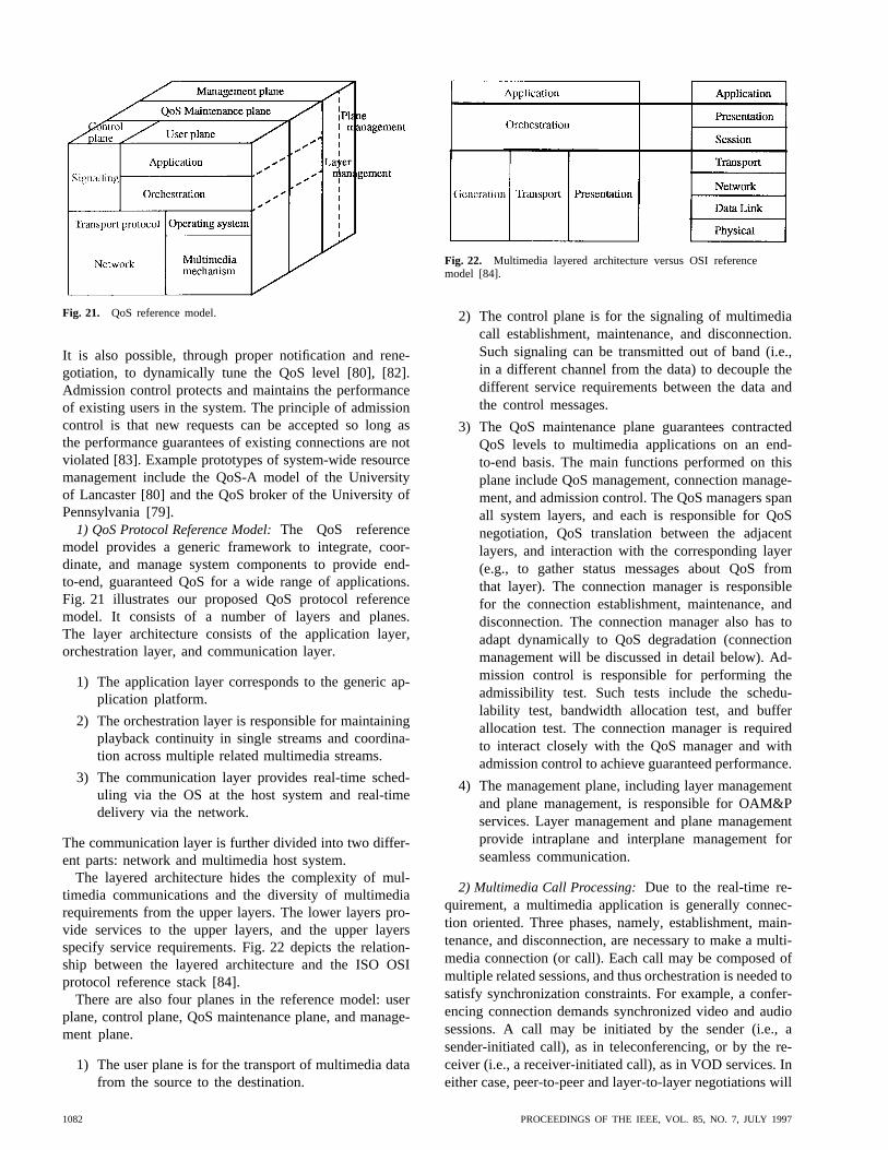
Fig. 21. QoS reference model.
It is also possible, through proper notification and rene-gotiation, to dynamically tune the QoS level [80], [82].Admission control protects and maintains the performanceof existing users in the system. The principle of admissioncontrol is that new requests can be accepted so long asthe performance guarantees of existing connections are notviolated [83]. Example prototypes of system-wide resourcemanagement include the QoS-A model of the Universityof Lancaster [80] and the QoS broker of the University ofPennsylvania [79].
1) QoS Protocol Reference Model:The QoS referencemodel provides a generic framework to integrate, coor-dinate, and manage system components to provide end-to-end, guaranteed QoS for a wide range of applications.Fig. 21 illustrates our proposed QoS protocol referencemodel. It consists of a number of layers and planes.The layer architecture consists of the application layer,orchestration layer, and communication layer.
1) The application layer corresponds to the generic ap-plication platform.
2) The orchestration layer is responsible for maintainingplayback continuity in single streams and coordina-tion across multiple related multimedia streams.
3) The communication layer provides real-time sched-uling via the OS at the host system and real-timedelivery via the network.
The communication layer is further divided into two differ-ent parts: network and multimedia host system.
The layered architecture hides the complexity of mul-timedia communications and the diversity of multimediarequirements from the upper layers. The lower layers pro-vide services to the upper layers, and the upper layersspecify service requirements. Fig. 22 depicts the relation-ship between the layered architecture and the ISO OSIprotocol reference stack [84].
There are also four planes in the reference model: userplane, control plane, QoS maintenance plane, and manage-ment plane.
1) The user plane is for the transport of multimedia datafrom the source to the destination.
Fig. 22. Multimedia layered architecture versus OSI referencemodel [84].
2) The control plane is for the signaling of multimediacall establishment, maintenance, and disconnection.Such signaling can be transmitted out of band (i.e.,in a different channel from the data) to decouple thedifferent service requirements between the data andthe control messages.
3) The QoS maintenance plane guarantees contractedQoS levels to multimedia applications on an end-to-end basis. The main functions performed on thisplane include QoS management, connection manage-ment, and admission control. The QoS managers spanall system layers, and each is responsible for QoSnegotiation, QoS translation between the adjacentlayers, and interaction with the corresponding layer(e.g., to gather status messages about QoS fromthat layer). The connection manager is responsiblefor the connection establishment, maintenance, anddisconnection. The connection manager also has toadapt dynamically to QoS degradation (connectionmanagement will be discussed in detail below). Ad-mission control is responsible for performing theadmissibility test. Such tests include the schedu-lability test, bandwidth allocation test, and bufferallocation test. The connection manager is requiredto interact closely with the QoS manager and withadmission control to achieve guaranteed performance.
4) The management plane, including layer managementand plane management, is responsible for OAM&Pservices. Layer management and plane managementprovide intraplane and interplane management forseamless communication.
2) Multimedia Call Processing:Due to the real-time re-quirement, a multimedia application is generally connec-tion oriented. Three phases, namely, establishment, main-tenance, and disconnection, are necessary to make a multi-media connection (or call). Each call may be composed ofmultiple related sessions, and thus orchestration is needed tosatisfy synchronization constraints. For example, a confer-encing connection demands synchronized video and audiosessions. A call may be initiated by the sender (i.e., asender-initiated call), as in teleconferencing, or by the re-ceiver (i.e., a receiver-initiated call), as in VOD services. Ineither case, peer-to-peer and layer-to-layer negotiations will
1082 PROCEEDINGS OF THE IEEE, VOL. 85, NO. 7, JULY 1997

take place [82]. Peer-to-peer negotiation is held between thecaller and callee. For example, to retrieve a video from aremote server, a user needs to negotiate with the server toget the best possible service. If there are enough resources,such as disk transfer bandwidth and network bandwidth,the new request can be granted; otherwise, the user may beoffered a lower quality of service. If the caller and calleeare in groups, group-to-group negotiation may be necessary.Layer-to-layer negotiation is held between adjacent layers.For example, in video conferencing, the application layerneeds to negotiate with the network layer to get multicastservices for group distribution. We now describe the threephases in detail.
a) Establishment:
• Service contract specification:describes the re-quired QoS constraints for the connection. Itshould include sufficient information to allow thesystem to make decisions on the granting or de-nial of the connection. It involves two steps: QoSnegotiation and QoS translation between adjacentlayers. QoS negotiation is described above. Oncethe negotiation is complete, QoS parameter trans-lation maps the QoS between two adjacent layers.For example, application QoS and system QoStranslation maps the application QoS parametersinto the system QoS parameters. QoS parametertranslation is essential to coordinate services indifferent layers. For example, packet loss param-eters mean little to the user but translate intopresentation glitches that the user cares about.Parameter mapping from distributed applicationplatforms to the ATM network in the QoS-Aproject of Lancaster [80] is an example.
• Admissibility test:determines if the connectionrequest is granted or denied. Based on the ser-vice contract negotiated, the admission test isperformed. If the request is denied, a degradedQoS level of service may be offered or the usermay be advised to attempt to get service later.
• Resource reservation and allocation:Resourcereservation is fundamental to end-to-end QoSguarantees. According to the negotiated QoSlevel, deterministic guarantee necessitates re-serving and allocating resources for the worstcase, such as the peak rate bandwidth, whilestatistical guarantee is based on the average caseand will provide satisfactory QoS with a certainprobability. Best-effort service does not guaranteeperformance. It is based on the resource-sharingprinciple and thus no resources are reserved orallocated in advance.
Resource reservation may be sender initiated(e.g., ST-II [85]) or receiver initiated (e.g.,RSVP13 [86]). The communication may be
13The RSVP protocol has been adopted by the IETF working groupto standardize and enhance the QoS support of the current Internetarchitecture. This approach will be discussed in detail in Section IV-C.
point to point (e.g., RCAP [87]) or point tomultipoint (e.g., ST-II and RSVP). With thesender-initiated approach, the sender transmitsthe reservation request toward the receiver(s)along with the path (for unicast) or the multicasttree that is rooted at the sender and extended toall receivers (for multicast). With the receiver-initiated approach, the receivers are responsiblefor making reservations.
• Notification of acceptance:Once the connectionhas been set up, the resource manager will informthe user of the acceptance.
b) Maintenance:
• QoS maintenance:A system-wide resource man-ager is required to manage the various systemcomponents and to perform admission control toguarantee the QoS of the existing connections.The packet loss model described in [83] accountsfor packet losses at both the server and thenetwork and can be used as the basis for system-wide admission control. QoS maintenance foreach component may include congestion controland flow control in the network as well as real-time scheduling at the host systems and mediaservers.
• QoS monitoring:QoS monitoring performs trafficpolicing to prevent the user from violating thenegotiated traffic characteristics. For example,traffic-shaping mechanisms such as the leakybucket [88] and the [89] schemes maybe applied. If the user violates the service con-tract, penalties may be imposed, such as loweringthe service priority or charging more.
• QoS adaptation:Since the traffic is dynamic,sometimes the system may be overloaded. If thenegotiated QoS cannot be guaranteed or the userwould like to change the negotiated parametervalues during the connection, renegotiation be-tween the user and the system will be required.
c) Disconnection:When a call terminates, the re-sources assigned to it are released and reallocated bythe system.
B. Data Compression
The objective of compression technology is to reducethe amount of data necessary to reproduce the originaldata while maintaining required levels of coded signalquality, processing delay, and implementation complexity[90]. Data compression plays a critical role in the manipu-lation of multimedia data because continuous media dataare typically large in volume and require real-time andcontinuous delivery and presentation. Without compression,existing computer platforms, storage devices, and networksare unable to satisfy the requirements of the massivestorage space, high data-transfer rate, and huge transmissionbandwidth typical of multimedia data. For example, the
LI AND LIAO: DISTRIBUTED MULTIMEDIA SYSTEMS 1083

transmission bandwidth requirement for digital video witha resolution of 640 by 480, 24-b colors, and 30 fps is640 480 24 7.4 Mb/f, and 7.4 Mb/f 30 fps
221 Mb/s. The bandwidth currently available is muchsmaller. For example, CD-ROM drives have 1.2–4.8 Mb/s,T1 lines 1.5 Mb/s, T3 lines around 45 Mb/s, coaxial cablesaround 40 Mb/s, and OC-3 optical fibers 155 Mb/s. Withoutdata compression, current technologies are inadequate forsupporting today’s video, and certainly inadequate for theHDTV-quality video in the future.
Compression schemes exploit and eliminate any redun-dancies within each frame (i.e., spatial redundancy, includ-ing space and color similarities) and between sequentialframes (i.e., temporal redundancy), resulting in the reduc-tion of data being stored and transmitted. The former iscalled intraframe compression and the latterinterframecompression. Note that squeezing the color similarities ex-ploits the artifacts of human vision, which is more sensitiveto luminance (i.e., brightness) than to chrominance (i.e.,color changes). Compression techniques can be categorizedbased on the following considerations.
1) Lossless or lossy:If the decompressed data is iden-tical to the original, it is referred to as losslesscompression; otherwise, lossy compression. Lossycompression schemes usually have higher compres-sion ratios but may introduce some compressionartifacts such as aliasing, a distortion or stair-stepeffect in the image. The baseline of lossy compressionis decided by the human eye.
2) Entropy encoding or source encoding:Entropy com-pression does not differentiate the types of data butanalyzes the statistical properties of data to reduce thesize. Source compression deals with the contents ofthe source material and makes use of their semanticand special characteristics to achieve data reduction.Entropy compression is usually lossless (such asrun-length coding and Huffman coding) and sourcecompression is usually lossy (such as discrete cosinetransform plus quantization).
3) Symmetrical or asymmetrical:If the time required tocompress and to decompress is roughly the same, it isreferred to as symmetrical compression. In asymmet-rical compression, the time taken for compression isusually much longer than decompression. Symmetricschemes are usually adopted in applications that mustdigitize and compress data in real time, such as videoconferencing. Asymmetrical schemes, on the otherhand, are often used when the data are compressedonce and decompressed many times, as in mostinteractive TV applications.
4) Software or hardware:The compression may beperformed by software or hardware. Hardware codecs(COder and DECoder) are faster and are suitable forCPU-intensive processing. Existing hardware codecsoften offer better quality and performance. However,they are available only on platforms with costly
extended hardware and dedicated hardware doomedto rapid obsolescence. Examples include JPEG,MPEG1, MPEG2,14 and DVI.15 Software codecsare suitable for less CPU-intensive processes andare limited to those processes capable of decodingan image within a frame period. Compatibility ofthe underlying hardware ensures wider consumeraccessibility, lower costs, and upward compatibility.Examples includes Indeo of Intel, Cinepack ofRadius, TrueMotion-S of Duck Corporation, MotionPixels, and Video Beam.
1) Basic Compression Techniques:Some compressionmethods are based on a particular technique and some(especially those for multimedia applications) are hybridsof several techniques. Some basic techniques are examinedfirst, and specific techniques applied to multimediaapplications will then be described.
a) Lossless compression:i) Run-length coding:In run-length coding, a string
of repeated symbols is replaced with the symbol andthe number of instances it is repeated. For example,“abaaaabbbbbbb” is expressed as “a1b1a4b7.”
ii) Variable-length coding: Variable-length codingencodes data based on the frequency of occurrence, withthe most frequently occurring data patterns replaced withshorter symbols. Huffman coding and arithmetic coding(in which data are encoded into numerical values) areexamples.
b) Lossy compression:i) Predictive encoding:Predictive encoding exploits
the redundancy from sample to sample and derives theupcoming sample from the previous sample, where thesample may be a pixel, line, audio sample, or video frame.It encodes, stores, and transmits the differences betweenthe prediction and the input sample value. The decoderproduces the prediction from the previous sample andreproduces the sample from both the prediction and thedifference value. Since the size of the difference betweensamples is usually smaller than that of the original sam-ple, the file size may be reduced. Its success, however,highly depends on the prediction function and the abilityto anticipate the changing signal [12]. This technique ismost suitable for digital audio or video encoding, in whichadjacent samples or frames are generally similar to eachother. ADPCM is an example of predictive encoding.
ii) Transform coding: Transform coding convertsdata from one domain to another that is more convenientfor compression. Of course, the inverse transform functionmust exist to allow conversion back to the original domain[91]. For example, DCT encoding transforms samples fromthe time domain to the frequency domain. The input of theDCT engine is a two-dimensional block, typically with 8
8 pixels. DCT transforms an 8 8 block of pixel colorvalues into an 8 8 matrix of spatial frequencies. The
14There are software JPEG and MPEG coders also.15In contrast to JPEG and MPEG, DVI is proprietary and requires the
support of special hardware to perform compression and decompression.
1084 PROCEEDINGS OF THE IEEE, VOL. 85, NO. 7, JULY 1997

Fig. 23. The steps of lossy JPEG compression.
lower frequencies (i.e., general information) are positionednear the upper-left corner, and the higher frequencies(i.e., sharp edges) are near the lower-right corner. Thecoefficients of the output DCT matrix are divided by thecorresponding entries of an 8 8 quantization table (-table). Each entry of the -table describes the quality factorof the corresponding DCT output coefficient. The lowerthe quality factor, the higher the magnitude of value. Forexample, for DCT compression, the lower frequencies aremore important than the higher ones. Therefore, a-tablewith smaller numbers near the upper-left corner and largerones near the lower-right corner is used. The division of theDCT output matrix by the -table causes the lower-right-corner portion of the resultant matrix to become mostlyzeros. As a result, the greater portion of the high-frequencyinformation is discarded. The modification of the-tableis one way to change the degree of compression. TheDCT decoder performs the reverse process and convertsthe 64 coefficients back to pixel values. Since quantizationis a lossy process, it may not reproduce the originalsexactly.
2) Multimedia Compression Techniques:a) Still image: A still image compression scheme
throws away the spatial and/or color redundancies. It canbe further divided into lossless (with compression ratios of2–5), such as run-length coding and variable-length coding,
and lossy (with compression ratios of 10–20), such as DCT,vector quantization, fractal, and wavelet coding.
The standard compression scheme for still images isJPEG [92], [93], which is a hybrid of several basic com-pression methods. JPEG, developed by the ISO and CCITT,is designed for arbitrary still images (i.e., continuous-toneimages) and supports four modes of encoding.
1) Lossless:the image is encoded in such a way that itis guaranteed to be restorable.
2) Sequential:the image is encoded in the order in whichit is scanned.
3) Progressive:the image is encoded in multiple passes,so that the entire content can be visualized in arough-to-clear process (i.e., refined during succeedingpasses).
4) Hierarchical: the image is encoded at multiple reso-lutions.
JPEG uses predictive encoding to achieve lossless com-pression and uses DCT encoding and quantization to per-form the other three operations. Since quantization is alossy algorithm, sequential, progressive, and hierarchicalencoding are lossy compressions. The basic steps of lossycompression (shown in Fig. 23) are summarized as follows.
LI AND LIAO: DISTRIBUTED MULTIMEDIA SYSTEMS 1085
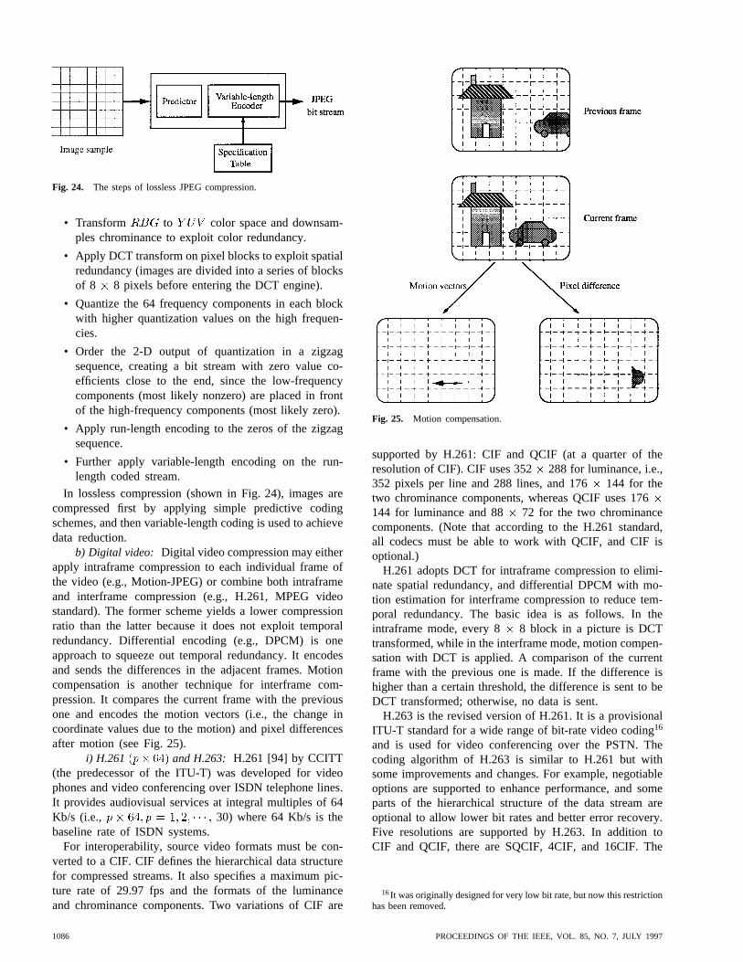
Fig. 24. The steps of lossless JPEG compression.
• Transform to color space and downsam-ples chrominance to exploit color redundancy.
• Apply DCT transform on pixel blocks to exploit spatialredundancy (images are divided into a series of blocksof 8 8 pixels before entering the DCT engine).
• Quantize the 64 frequency components in each blockwith higher quantization values on the high frequen-cies.
• Order the 2-D output of quantization in a zigzagsequence, creating a bit stream with zero value co-efficients close to the end, since the low-frequencycomponents (most likely nonzero) are placed in frontof the high-frequency components (most likely zero).
• Apply run-length encoding to the zeros of the zigzagsequence.
• Further apply variable-length encoding on the run-length coded stream.
In lossless compression (shown in Fig. 24), images arecompressed first by applying simple predictive codingschemes, and then variable-length coding is used to achievedata reduction.
b) Digital video: Digital video compression may eitherapply intraframe compression to each individual frame ofthe video (e.g., Motion-JPEG) or combine both intraframeand interframe compression (e.g., H.261, MPEG videostandard). The former scheme yields a lower compressionratio than the latter because it does not exploit temporalredundancy. Differential encoding (e.g., DPCM) is oneapproach to squeeze out temporal redundancy. It encodesand sends the differences in the adjacent frames. Motioncompensation is another technique for interframe com-pression. It compares the current frame with the previousone and encodes the motion vectors (i.e., the change incoordinate values due to the motion) and pixel differencesafter motion (see Fig. 25).
i) H.261 and H.263: H.261 [94] by CCITT(the predecessor of the ITU-T) was developed for videophones and video conferencing over ISDN telephone lines.It provides audiovisual services at integral multiples of 64Kb/s (i.e., 30) where 64 Kb/s is thebaseline rate of ISDN systems.
For interoperability, source video formats must be con-verted to a CIF. CIF defines the hierarchical data structurefor compressed streams. It also specifies a maximum pic-ture rate of 29.97 fps and the formats of the luminanceand chrominance components. Two variations of CIF are
Fig. 25. Motion compensation.
supported by H.261: CIF and QCIF (at a quarter of theresolution of CIF). CIF uses 352 288 for luminance, i.e.,352 pixels per line and 288 lines, and 176144 for thetwo chrominance components, whereas QCIF uses 176144 for luminance and 88 72 for the two chrominancecomponents. (Note that according to the H.261 standard,all codecs must be able to work with QCIF, and CIF isoptional.)
H.261 adopts DCT for intraframe compression to elimi-nate spatial redundancy, and differential DPCM with mo-tion estimation for interframe compression to reduce tem-poral redundancy. The basic idea is as follows. In theintraframe mode, every 8 8 block in a picture is DCTtransformed, while in the interframe mode, motion compen-sation with DCT is applied. A comparison of the currentframe with the previous one is made. If the difference ishigher than a certain threshold, the difference is sent to beDCT transformed; otherwise, no data is sent.
H.263 is the revised version of H.261. It is a provisionalITU-T standard for a wide range of bit-rate video coding16
and is used for video conferencing over the PSTN. Thecoding algorithm of H.263 is similar to H.261 but withsome improvements and changes. For example, negotiableoptions are supported to enhance performance, and someparts of the hierarchical structure of the data stream areoptional to allow lower bit rates and better error recovery.Five resolutions are supported by H.263. In addition toCIF and QCIF, there are SQCIF, 4CIF, and 16CIF. The
16It was originally designed for very low bit rate, but now this restrictionhas been removed.
1086 PROCEEDINGS OF THE IEEE, VOL. 85, NO. 7, JULY 1997

Fig. 26. Different types of MPEG frames.
resolution of SQCIF is about half that of QCIF, 4CIF fourtimes that of CIF, and 16CIF 16 times that of CIF.
ii) MPEG video: Unlike H.261, which is optimizedfor teleconferencing where motion is naturally limited,the ISO MPEG video standard is devised for a widerange of video and motion pictures17 [95], [96]. It definesthe structure of coded video bit streams transmitted tothe decoder and the decoder architecture but leaves theencoder18 architecture undefined, so that some encodersmay produce higher quality compression, some will be real-time, and some will require manual intervention. MPEGcompression is lossy and asymmetric, with the encodingmore expensive than the decoding.
MPEG uses both intraframe and interframe techniques fordata compression. There are three types of encoded frames:I (intraframe), P (predicted), and B (bidirectional), as shownin Fig. 26. An I-frame contains all of the necessary informa-tion to reproduce a complete frame and thus is independentof any other frames in the video sequence. It basicallyapplies the intraframe compression of the basic JPEG DCTalgorithm. A P-frame is predicted from the differencesfrom the previous I- or P-frame in the sequence. A B-frame is bidirectional interpolated by the preceding and thesubsequent I- or P-frames. The interframe dependency of P-and B-frames implies that a current P-frame can be decodedonly if the preceding I- or P-frame has been presentedto be decoded. Similarly, without both the preceding andsubsequent I- or P-frames in the decoder, it is impossible togenerate a B-frame. For example, if the presentation orderof a video sequence is IBBPBBPBBI then the actualinput sequence of MPEG frames to a decoder should be
17The goal of MPEG is to define a standard for coded representationof moving pictures, associated audio, and the system.
18The basic requirement of MPEG encoders is to produce MPEG-compatible video.
IPBBPBBIBB Therefore, the patterns of video framesequence in storage and during transmission are differentfrom that for presentation. The basic compression steps are:
1) preprocess and color subsample;
2) for I-frame, skip this step; for P-frame and B-frame,do interframe motion compensation;
3) transform 8 8 pixel blocks to an 8 8 frequencycoefficient matrix, and send 8 8 blocks (eitherintrablocks or motion-compensated blocks) to theDCT engine and quantizer;
4) apply zigzag ordering on the 8 8 quantized coef-ficients;
5) apply run-length encoder to the zeros of the zigzagsequence;
6) apply variable-length encoder on the run-length codedstream.
There are different versions of MPEG, denoted by MPEG-x. MPEG-1 (i.e., the first version) was targeted at CD-ROMand applications at a bit rate of about 1.5 Mb/s. The video isstrictly progressive (i.e., noninterlaced) and picture qualityis equivalent to VHS. MPEG-2 addresses high-qualitycoding for all digital transmissions of broadcast-TV-qualityvideo at data rates of 2–15 Mb/s. The major applicationsinclude digital storage media, digital television (includ-ing HDTV)19, broadcasting over cable, satellite, and otherbroadcast channels, and other communications applications[97]. MPEG-2 is backward compatible to MPEG-1. Theprimary enhancement is centered around the addition ofinterlaced video. Thus, there are two coding structures(field and frame) in MPEG-2. Other improvements includeenhancements on coding efficiency. MPEG-4 is now in theapplication-identification stage. It targets applications withvery low bit rates of 4.8–64 Kb/s, such as videophone overthe PSTN and visual transmission over mobile facilities.
c) Digital audio: Compression of entertainment-quality audio signals has been widely studied, from-lawcompanding and ADPCM to the more recent MPEGaudio standard and Dolby AC-3 with high fidelity andsurround-sound effect. PCM produces the highest audioquality with no compression loss. Compared to PCM,
-law is of low complexity but often produces poor qualitycompressed audio; ADPCM is of medium complexity andproduces average quality; and MPEG audio and DolbyAC-3 produce the highest quality compressed audio withno perceivable loss compared to PCM.
i) -law companding: -law is widely used to en-code speech over telephone lines in the United States andJapan. A similar approach called A-law is used in Europe.The basic idea is to use quantization steps of differentsizes that increase logarithmically with the signal levelsto compress the signal, and to use the inverse functionto expand the signal. As a result, the quantization levelsare spaced far apart when the signal is louder and closer
19Originally, HDTV applications were addressed by MPEG-3, buteventually they were folded into MPEG-2.
LI AND LIAO: DISTRIBUTED MULTIMEDIA SYSTEMS 1087

(a)
(b)
Fig. 27. The block diagram of MPEG/audio encoder/decoder. (a) MPEG/audio encoder. (b)MPEG/audio decoder.
together when the signal is quieter [12]. The logarithmiccharacteristic of -law is
for
where is the magnitude of the output,is the magnitudeof the input, and is a positive parameter used to definethe desired compression level is often set to 255 forstandard telephone lines).
ii) ADPCM: ADPCM takes advantage of the factthat consecutive audio samples are generally similar andemploys adaptive quantization with fixed prediction. In-stead of quantizing each audio sample independently, asin PCM, an ADPCM encoder calculates the differencebetween each audio sample and its predicted value andoutputs the quantized difference (i.e., the PCM value of thedifferential). The performance is improved by employingadaptive prediction and quantization so that the predictorand difference quantizers adapt to the characteristics of theaudio signal by changing the step size. The decoder recon-structs the audio sample by using the identical quantizationstep size to obtain a linear difference plus possibly adding1/2 for the correction of truncation errors, and then addingthe quantized difference to its predicted value.
The method of calculating the predicted value and theway of adapting the audio signal samples vary amongdifferent ADPCM coding systems. For example, the AD-PCM algorithm proposed by the IMA takes 16-b linearPCM samples and outputs 4-b ADPCM samples, yieldinga compression factor of 4 : 1.
iii) MPEG audio: MPEG audio compression em-ploys perceptual coding that takes advantage of thepsychoacoustic phenomena and exploits human auditorymasking to squeeze out the acoustically irrelevant parts ofaudio signals [98]. Audio masking is a perceptual weaknessof human ears. Whenever a strong audio signal is present,the spectral neighborhood of weaker audio signals becomesimperceptible. Measurements of human hearing sensitivity
have shown that the ear integrates audio signals that arevery close in frequency and treats them as a group. Onlywhen the signals are sufficiently different in frequency willthe ear perceive the loudness of each signal individually.In perceptual coding, the audio spectrum is divided into aset of a narrow frequency bands, called critical bands, toreflect the frequency selectivity of human hearing. Then itis possible to filter coding noise sharply to force it to stayclose to the frequency of the frequency components of theaudio signal being coded, thereby masking out the noise.By reducing the coding noise when no audio is present andallowing strong audio to mask the noise at other times, thesound fidelity of the original signals can be perceptuallypreserved.
Fig. 27 shows the block diagram of MPEG/audio encod-ing and decoding [98]. The audio input is transformed fromthe time domain to the frequency domain. It then passesthrough a filter bank, which divides the resultant spectruminto multiple subbands. Simultaneously, the input streamgoes through a psychoacoustic model, which exploits au-ditory masking and determines the signal-to-noise ratio ofeach subband. The bit/noise allocation block determines thenumber of code bits allocated to quantize each subbandso that the audibility of quantization noise is minimized.The quantized samples are then formatted into a series ofbit streams. The decoder performs the inverse operation ofthe encoder and reconstructs the bit stream to time-domainaudio signals. To provide different quality and differentbit rates, the standard supports three distinct layers forcompression: layer I is the most basic and simplest codingalgorithm, and layers II and III are enhancements of layer I.
MPEG-2 audio is being developed for low-bit-rate codingof multichannel audio. It has 5.1 channels correspondingto five full range channels of audio, including three frontchannels (i.e., left, center, right) plus two surrounds, anda low-frequency bass-effect channel called the subwoofer.Since the subwoofer has only limited frequency response(about 100 Hz), it is sometimes referred to as the “.1”channel. In addition to two main channels (left and right)
1088 PROCEEDINGS OF THE IEEE, VOL. 85, NO. 7, JULY 1997

backward compatible to MPEG-1 audio, MPEG-2 audiouses new coding methods and syntax for the surroundchannels.
iv) Dolby AC-3: Dolby AC-3 is a multichannel per-ceptual coding technology used in Dolby Digital filmsoundtracks and the new Dolby Digital (Surround AC-3)home-theater equipment, such as laser discs [99]. Contraryto MPEG2 audio, Dolby AC-3 is not backward compatibleto MPEG1 audio. Using sophisticated audio masking anda shared bit-pool arrangement for audio-noise reduction,AC-3 achieves very effective data reduction and offerssound quality extremely close to the original. It enableshigh fidelity, 5.1-channel surround sound to be encoded inless space than that required by a single channel on a CD.
Dolby AC-3 has been officially adopted by the GrandAlliance20 to provide digital surround sound in the forth-coming U.S. HDTV audio system and is being used forDBS in two-channel form. In addition, Digital Cable TVand DVD have adopted AC-3, and DVC and DAB may doso as well.
C. Networking
The communication network, encompassing the transmis-sion media and the transport protocols, transports multime-dia traffic to satisfy QoS guarantees on an end-to-end basis.According to application requirements, the transmissionmedia may be wired (twisted pair, coaxial cable, fiberoptics) or wireless (radio channels, satellite channels) andthe transport protocols may provide connection-orientedor connectionless services and best-effort, statistical, ordeterministic performance guarantees. With respect to thetaxonomy of the geographical coverage area, the networkcan be a LAN, a MAN, or a WAN. A LAN (e.g., Ethernet,token ring, token bus) may cover an area within a building,a campus, or an organization; a MAN (e.g., FDDI, DQDB)may cover a metropolitan area, such as a small city; a WAN(e.g., TCP/IP, ATM) is a nationwide or an internationalnetwork.
To support multimedia applications, the network mustsatisfy the requirements for multimedia data transmission.Multimedia traffic has diverse characteristics and variousQoS requirements. Discrete media traffic (e.g., file transfer,image retrieval) requires error-free services but is tolerantof delay. Continuous media traffic (e.g., video or audioplayback), on the other hand, requires real-time, high-speedtransmission and is connection oriented. It is sensitive to de-lay and delay jitter, or the packet delay variations betweenconsecutive packets, but is tolerant of occasional packetlosses. In addition, the network has to support application-specific requirements. For example, video conferencingneeds multicast service for group distribution, and ITVrequires switched, point-to-point services and asymmetric
20The Digital HDTV Grand Alliance, announced on May 24, 1993,represents the merging of technologies from the three groups that haddeveloped all-digital HDTV systems for consideration as the U.S. standard:AT&T and Zenith Electronics Corporation, General Instrument Corpo-ration and the Massachusetts Institute of Technology, and a consortiumcomposed of Thomson Consumer Electronics, Phillips Consumer Elec-tronics, and the David Sarnoff Research Center.
bandwidth for the downstream (video server to user) andthe upstream (user to video server) directions.
The Internet has rapidly evolved into a significant net-work infrastructure for communication. It runs the Internetprotocol (IP) with its best-effort delivery service and enjoysa large user base. Another promising technique, ATM,is rapidly appearing in the market due to the extensivesupport of telephone companies. It allows bandwidth ondemand and guaranteed QoS and is expected to be thebest candidate for high-quality media delivery. We willexamine the Internet effort on the support of multimediatransmission, the elegant properties of ATM that make itespecially suited for distributed multimedia applications,and the issues of integrating ATM networks with theemerging integrated services Internet.
1) IP: Internet refers to the global network to which alarge percentage of existing networks are now intercon-nected by routers or gateways, running the TCP/IP protocolsuite. IP is the key to success for the Internet. It providesdatagram delivery (best effort, connectionless) service andleaves the reliability issues (delay, out-of-order delivery,packet losses, misdelivery) to the end systems. It uses aglobal addressing scheme for a vast range of services. Eachdatagram, in addition to data, carries routing informationin the header so as to be independently forwarded to thedestination.
The primitive service model of the Internet provides onlypoint-to-point and best-effort services. Such services areparticularly suited for traditional applications such as filetransfer and remote login. It performs well for real-timemedia traffic (e.g., video, audio) only under lightly loadednetworks. The support of IP multicast, resource reservation,and higher level RTP’s are the major development effortson the Internet geared toward multimedia applications. Wewill examine these three issues next.
a) IP multicast: Multicast refers to the ability to senda single packet to multiple destinations. Applications thatrequire multicast include teleconferencing, e-mail multicast,Usenet news, remote learning, and group communication.Traditional protocols such as TCP or UDP provide onlyunicast transmission. The provision of multicast with uni-cast services requires the delivery of replicated unicastpackets to each recipient. To avoid sending multiple repli-cated unicast copies, thereby increasing network utilization,multicast transport service is required. With IP multicast,each data source sends a packet to a multicast addressand lets the network forward a copy of the packet to eachof a group of hosts. Fig. 28 shows the difference betweenunicast and multicast transport services. The basic transportservice of IP multicast is unreliable multicast transmissionof datagrams, which is suitable for applications geared moretoward performance than reliability. A reliable protocol forIP multicast called MTP [100] has been developed to ensureatomicity and reliability.
Multicast routing protocols provide a mechanism thatenables routers to propagate multicast datagrams in such away as to minimize the number of excess copies transmittedto any particular subnetwork. In addition, they must be
LI AND LIAO: DISTRIBUTED MULTIMEDIA SYSTEMS 1089
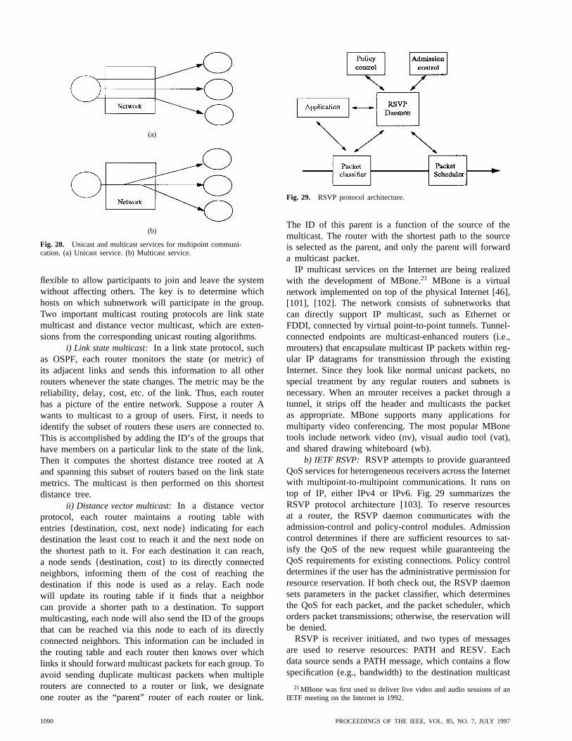
(a)
(b)
Fig. 28. Unicast and multicast services for multipoint communi-cation. (a) Unicast service. (b) Multicast service.
flexible to allow participants to join and leave the systemwithout affecting others. The key is to determine whichhosts on which subnetwork will participate in the group.Two important multicast routing protocols are link statemulticast and distance vector multicast, which are exten-sions from the corresponding unicast routing algorithms.
i) Link state multicast: In a link state protocol, suchas OSPF, each router monitors the state (or metric) ofits adjacent links and sends this information to all otherrouters whenever the state changes. The metric may be thereliability, delay, cost, etc. of the link. Thus, each routerhas a picture of the entire network. Suppose a router Awants to multicast to a group of users. First, it needs toidentify the subset of routers these users are connected to.This is accomplished by adding the ID’s of the groups thathave members on a particular link to the state of the link.Then it computes the shortest distance tree rooted at Aand spanning this subset of routers based on the link statemetrics. The multicast is then performed on this shortestdistance tree.
ii) Distance vector multicast:In a distance vectorprotocol, each router maintains a routing table withentries {destination, cost, next node} indicating for eachdestination the least cost to reach it and the next node onthe shortest path to it. For each destination it can reach,a node sends {destination, cost} to its directly connectedneighbors, informing them of the cost of reaching thedestination if this node is used as a relay. Each nodewill update its routing table if it finds that a neighborcan provide a shorter path to a destination. To supportmulticasting, each node will also send the ID of the groupsthat can be reached via this node to each of its directlyconnected neighbors. This information can be included inthe routing table and each router then knows over whichlinks it should forward multicast packets for each group. Toavoid sending duplicate multicast packets when multiplerouters are connected to a router or link, we designateone router as the “parent” router of each router or link.
Fig. 29. RSVP protocol architecture.
The ID of this parent is a function of the source of themulticast. The router with the shortest path to the sourceis selected as the parent, and only the parent will forwarda multicast packet.
IP multicast services on the Internet are being realizedwith the development of MBone.21 MBone is a virtualnetwork implemented on top of the physical Internet [46],[101], [102]. The network consists of subnetworks thatcan directly support IP multicast, such as Ethernet orFDDI, connected by virtual point-to-point tunnels. Tunnel-connected endpoints are multicast-enhanced routers (i.e.,mrouters) that encapsulate multicast IP packets within reg-ular IP datagrams for transmission through the existingInternet. Since they look like normal unicast packets, nospecial treatment by any regular routers and subnets isnecessary. When an mrouter receives a packet through atunnel, it strips off the header and multicasts the packetas appropriate. MBone supports many applications formultiparty video conferencing. The most popular MBonetools include network video (nv), visual audio tool (vat),and shared drawing whiteboard (wb).
b) IETF RSVP: RSVP attempts to provide guaranteedQoS services for heterogeneous receivers across the Internetwith multipoint-to-multipoint communications. It runs ontop of IP, either IPv4 or IPv6. Fig. 29 summarizes theRSVP protocol architecture [103]. To reserve resourcesat a router, the RSVP daemon communicates with theadmission-control and policy-control modules. Admissioncontrol determines if there are sufficient resources to sat-isfy the QoS of the new request while guaranteeing theQoS requirements for existing connections. Policy controldetermines if the user has the administrative permission forresource reservation. If both check out, the RSVP daemonsets parameters in the packet classifier, which determinesthe QoS for each packet, and the packet scheduler, whichorders packet transmissions; otherwise, the reservation willbe denied.
RSVP is receiver initiated, and two types of messagesare used to reserve resources: PATH and RESV. Eachdata source sends a PATH message, which contains a flowspecification (e.g., bandwidth) to the destination multicast
21MBone was first used to deliver live video and audio sessions of anIETF meeting on the Internet in 1992.
1090 PROCEEDINGS OF THE IEEE, VOL. 85, NO. 7, JULY 1997

address. When a router receives a PATH message, it recordsthe relevant information (e.g., IP multicast address, flowspecification, source ID, etc.). As a result, not only arethe receivers informed of the flow specification of thedata traffic but the intermediate nodes also obtain thePATH state information. Based on information obtainedfrom PATH messages and from higher layer protocols,each receiver can determine its QoS requirements andinitiate a RESV message to reserve specific resourcesalong the reserved route of the PATH message. Multiplereceivers may send RESV messages toward the samedata source. These RESV messages are merged as theytravel up the multicast tree, and only the merged RESVis forwarded toward the source. Thus, RSVP scales welland accommodates heterogeneous receiver requirements.Resources will then be reserved along the route from thesource toward the receiver.
For reliability and robustness, RSVP periodically updatesthe soft states at intermediate routers to allow for usersjoining and leaving a group, where the soft state refers to“a state maintained at network switches which, when lost,will be automatically reinstalled by RSVP soon thereafter”[86].
Presently, three reservation styles have been defined:fixed filter, wildcard filter, and shared explicit [104]. Fixedfilter allows explicit sender selection and distinct reserva-tion and is suitable for applications such as video confer-encing, in which each video stream has its own RSVP flow.Explicit sender selection refers to the reservation made onlyfor senders explicitly listed in the RESV message, whilewildcard sender selection includes any sender. Distinctreservation means that each sender has its own RSVP flow,while shared reservation uses the same RSVP flow formultiple senders. Wildcard filter allows wildcard sender se-lection and shared reservation. It is suitable for applicationssuch as audio conferencing, in which participants typicallytake turns speaking. Shared explicit allows explicit senderselection and shared reservation. It is similar to wildcardfilter but with better security.
c) RTP: RTP provides end-to-end data-transport ser-vices for the delivery of real-time data (e.g., video, audio)over unicast or multicast networks [105]. The data transportis augmented by the RTCP to monitor QoS and provideminimal control, management, and identification. RTP andRTCP are independent of the transport protocols and theunderlying network, although they are typically run ontop of UDP/IP and IP multicast. Except for framing, RTPmakes no specific assumptions on the capabilities of thelower layers. It does not perform resource reservation, andno QoS guarantees are made. In addition, no mechanismsare defined for flow control and reliability. Timely de-livery relies only on the support of lower-layer servicessuch as RSVP that have control over the resources innetworks. The functionalities of RTP include time stamping,sequence numbering, timing reconstruction, loss detec-tion, and channel and content identification. Based on thetiming information and sequence number carried in theRTP header, receivers are allowed to reconstruct and to
(a)
(b) (c)
Fig. 30. The ATM virtual path concept. (a) Virtual paths, virtualchannels, links, and nodes. (b) Routing table at node 2. (c) VP,VC identifiers in a cell.
play audio and video sequences despite occasional loss ormisdelivery of packets.
2) ATM: ATM technology was selected to support B-ISDN by international standards bodies such as the ITU-T,ETSI, and ANSI. Although originally designed for WAN’s,it is also suited for LAN’s and MAN’s and therefore isthe perfect vehicle for their seamless integration. ATM isbasically virtual circuit switching enhanced by the virtualpath concept. It uses small, fixed-size cells (53 bytes, fivefor header and 48 for payload) and simple communicationprotocols to reduce per-cell processing and to speed upswitching.
In virtual circuit switching, a virtual circuit routing tableis required at each intermediate node of the path to directeach packet (known as a cell in ATM terminology) ofa virtual circuit (or virtual channel) to the appropriateoutgoing link. Since there may be a large number of virtualchannels, and many of them may have the same originand destination, one may reduce the size of routing tablesin the transit nodes by grouping those virtual channelssharing the same origin-destination pairs into a virtual path.For example, in Fig. 30, virtual channels VC1, VC2, andVC3 are grouped into virtual path VP1; VC4 and VC5are grouped into VP2; and VP3 contains only one virtualchannel, namely, VC6. The packet header includes a VPIand a VCI. A connection or call is assigned a virtualchannel. The end node uses the VCI of the cell to direct itto the corresponding terminal. At the transit nodes, the VPIof the cell provides enough information to direct this cellto the corresponding path in the network.
LI AND LIAO: DISTRIBUTED MULTIMEDIA SYSTEMS 1091

Fig. 31. ATM protocol stacks versus OSI protocol stacks.
The ATM network has a layered structure allowingmultimedia traffic to be mixed in the network. It includesthe upper-layer, AAL, the ATM layer, and the physicallayer. Fig. 31 shows the relationship between the ATMlayer structure and the OSI protocol stacks, and Fig. 32shows the role of the ATM layered structure in the ATMnetwork.
• The upper layer includes higher layer protocols suchas TCP, RTP, and Xpress Transport Protocol [106].
• The AAL layer adapts the upper layer protocols tothe ATM format. It inserts or extracts user informa-tion as 48-byte payloads. The AAL layer consistsof two sublayers: the CS and the SAR. The CSconverges different types of user traffic and encap-sulates/decapsulates data flow to and from the SARsublayer. The SAR sublayer in the sender segmentsdata into a series of 48-byte cells, and in the re-ceiver reassembles cell sequences back to the originaldata.
• The ATM layer adds or strips the 5-byte header toor from the payload. For the sender, it takes 48-bytedata from the AAL and adds the 5-byte header thatcontains routing information to ensure that the cell issent on the right connection; for the receiver, it stripsthe 5-byte header and passes the 48-byte payload tothe corresponding AAL.
• The physical layer defines the electrical characteristicsand network interfaces and places ATM cells into thetransmission medium. The ATM network is not tied toa specific type of physical medium but is optimized towork with the SONET.
CCITT and other standards bodies have identified fiveclasses of ATM services.
1) Class A: supports CBR traffic, in which the sourcegenerates a constant number of bits per unit time.Examples include continuous media traffic such asvoice and uncompressed video. This type of traffic istolerant of some packet losses but very sensitive todelay jitter. Bandwidth required is moderate for CBRvoice and very high for uncompressed video.
Fig. 32. ATM network.
2) Class B: supports VBR stream traffic, in which thesource generates a variable number of bits per unittime. This is exemplified by compressed video22
such as MPEG. Like CBR, it is sensitive to packetdelay variations. In addition, since there are lessredundancies in compressed data, it is not tolerant ofpacket losses. Bandwidth required for video is veryhigh. The traffic is highly bursty and exhibits multipletime scale variation, with the bit-rate requirementsvarying over milliseconds (within one frame of thevideo), over seconds (between frames), and overminutes (between scene changes).
3) Class C:supports connection-oriented framed data.
4) Class D: supports connectionless (datagram) frameddata (e.g., SMDS).
5) Class X:supports data traffic requiring raw cell de-livery using proprietary, nonstandardized protocols.
Note that for Classes A and B, a timing relation isrequired between the sender and the receiver, while for theother classes, a strict timing relation is not required. ClassesC, D, and X correspond to VBR services. To support thesefive classes of services, four types of AAL formats havebeen developed. AAL Type 1 supports Class A, Type 2supports Class B, Type 3/4 supports Classes C and D, andType 5 supports Class X.
Even with an ATM network, it is difficult to providetrue VBR service. One way to satisfy the QoS requirementof VBR traffic is to allocate bandwidth equal to the peaktraffic rate. This will give a hard QoS guarantee but is veryinefficient. One can exploit the statistical multiplexing ofATM networks and allocate a bandwidth equal to the meantraffic rate, but this will only give a statistical guaranteeof the QoS. Another solution is to use buffers to smoothor shape the traffic so that it approximates CBR traffic[107]. In particular, to accommodate the multiple time scaleburstiness exhibited by compressed video, a quasi-staticbandwidth allocation scheme [108] may be used. In thisscheme, developed for VOD systems, certain bandwidth isinitially allocated to the connection. As the traffic fluctuates,the amount of video in the video buffer changes. The videobuffer is monitored, and if buffer overflow or underflow is
22Compressed video may also be sent as CBR traffic with less resolutionfor a complex scene and higher resolution for simple scenes, but this isless desirable than VBR video.
1092 PROCEEDINGS OF THE IEEE, VOL. 85, NO. 7, JULY 1997

imminent, a request will be made to change the bandwidthallocated to the connection. In addition, since VBR traffic issensitive to packet losses, one needs to have an admissioncontrol scheme to limit the packet losses or employ error-recovery schemes. For example, the receiver may attemptto reconstruct the missing data through temporal or spatialinterpolation [109].
3) The Integration of IP and ATM:The two major con-tenders as the protocol for global internetworking are IPand ATM. There are major obstacles to either’s success.The strength of IP is the large installed base. It is theprotocol used on the Internet, which is the biggest andfastest-growing computer network in the world. The In-ternet is a packet-switched network and basically providesconnectionless and best-effort transport services. The majorproblem is that the best-effort delivery of messages doesnot support the various QoS required in a true integratedservices network. In addition, the existing Internet has verylimited bandwidth, although there are plans to upgradeit to higher bandwidth. The development of IP multi-cast, resource reservation protocols, and real-time transportprotocols allows the Internet to provide limited forms ofmultimedia services. Even with the upgraded bandwidth,the Internet will be inadequate for many multimedia appli-cations, such as VOD.
On the other hand, the ATM network is connectionoriented. The strength of ATM lies in the possibility ofsetting up connections with a class of service that matchesthe requirements of the application involved. The plannedbit rates and bit error rates also meet the requirements ofreal-time transmission of audio and video streams. ATMworks best in an environment where everyone uses ATM,however, and the major obstacle is the large installed baseof non-ATM equipment. Whether ATM or IP or anotherprotocol will eventually emerge as the global internet-working protocol, only time will tell. In the meantime,the Internet community is developing resource reservationprotocols such as RSVP [86] that give QoS guarantees.In addition, IP over ATM has been successfully deployed[104]. The future global internetworking protocol will likelybe one that supports QoS guarantees and may include bothATM and IP technologies.
D. Multimedia Operating System
OS’s manage computer resources (e.g., CPU, memory,I/O devices, etc.), hide the physical characteristics of the un-derlying hardware, and provide an efficient and convenientenvironment for end users. A multimedia OS extends thefunctionalities of traditional OS’s to accommodate multime-dia data manipulation so as to provide an environment forreal-time support while simultaneously running traditionalapplications efficiently. The major concerns include real-time processing and QoS-based resource management. To-gether they ensure that the QoS requirements of multimediaapplications are met and provide intelligent overload controlfor transient misses of playback deadlines. A multimediaOS may be developed as an extension of a traditional OS orconstructed from scratch using the microkernel architecture
(e.g., Chorus [110], Real-Time Mach [111]). In any case,it should provide CPU management, memory management,I/O management, and file system management.
1) CPU Management:Real-time processing can beachieved through efficient real-time scheduling. Real-time schedulers schedule tasks to make their deadlines.In the context of continuous media, a deadline can be theacceptable playback time of each frame, and therefore itis a soft deadline and appears periodically. The challengesof multimedia scheduling are due to two conflicting goals[112].
1) Nonreal-time processes should not suffer from theexecution of real-time processes, since multimediaapplications equally depend on discrete and contin-uous media data. Thus, real-time processes cannotmonopolize all resources.
2) Real-time processes should be allowed to preemptnonreal-time processes or other real-time processeswith lower priorities.
The most important real-time scheduling approaches in-clude EDF and rate-monotonic scheduling [113]. WithEDF, each task is preemptive and is assigned a priorityaccording to the deadline. The highest priority is assignedto the job with the earliest deadline, and tasks are ex-ecuted in priority order. When a new task arrives, thescheduler recomputes the priorities of all pending tasksand then reorganizes the order of processing. If the newarrival has the highest priority, the task being executed ispreempted and the new task gets served immediately. Theinterrupted process is resumed later from the interruptionpoint. Otherwise, the new task will be put in an appropriateposition.
With rate-monotonic scheduling, each task is preemptiveand is assigned a priority according to the request rate.The highest priority is assigned to the job with the highestrate. In contrast to EDF, such assignment is performedonly at the connection establishment time and is maintainedthroughout the lifetime of the connection. For preemptive,periodic tasks, rate-monotonic scheduling is optimal in thesense that “no other static algorithm can schedule a taskset that the rate-monotonic algorithm cannot also schedule”[112].
Comparing these two algorithms, EDF is more dynamic.It has to be executed frequently and thus incurs higherscheduling overhead. The advantage is that it can achieveprocessor utilization up to 100%. A rate-monotonic al-gorithm, on the other hand, is static since the priorityassignment is only calculated once. Since the prioritiesare assigned according to the request rate, more contextswitches occur in rate-monotonic scheduling than in EDF.The worst case upper bound of the process utilization isabout 69% (or 2) even though, on the average, theutilization far exceeds 80%. However, because it has noscheduling overhead and is optimal for periodic jobs, rate-monotonic scheduling is suitable for continuous mediaapplications.
LI AND LIAO: DISTRIBUTED MULTIMEDIA SYSTEMS 1093
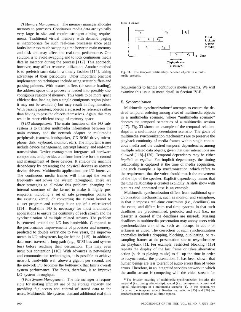
2) Memory Management:The memory manager allocatesmemory to processes. Continuous media data are typicallyvery large in size and require stringent timing require-ments. Traditional virtual memory with demand pagingis inappropriate for such real-time processes since pagefaults incur too much swapping time between main memoryand disk and may affect the real-time performance. Onesolution is to avoid swapping and to lock continuous mediadata in memory during the process [112]. This approach,however, may affect resource utilization. Another methodis to prefetch such data in a timely fashion [114], takingadvantage of their periodicity. Other important practicalimplementation techniques include using scatter buffers andpassing pointers. With scatter buffers (or scatter loading),the address space of a process is loaded into possibly dis-contiguous regions of memory. This tends to be more spaceefficient than loading into a single contiguous region (sinceit may not be available) but may result in fragmentation.With passing pointers, objects are passed by reference ratherthan having to pass the objects themselves. Again, this mayresult in more efficient usage of memory space.
3) I/O Management:The main function of the I/O sub-system is to transfer multimedia information between themain memory and the network adapter or multimediaperipherals (camera, loudspeaker, CD-ROM drive, micro-phone, disk, keyboard, monitor, etc.). The important issuesinclude device management, interrupt latency, and real-timetransmission. Device management integrates all hardwarecomponents and provides a uniform interface for the controland management of these devices. It shields the machinedependency by presenting the physical devices as abstractdevice drivers. Multimedia applications are I/O intensive.The continuous media frames will interrupt the kernelfrequently and lower the system throughput. There arethree strategies to alleviate this problem: changing theinternal structure of the kernel to make it highly pre-emptable, including a set of safe preemption points tothe existing kernel, or converting the current kernel toa user program and running it on top of a microkernel[114]. Real-time I/O is necessary for most multimediaapplications to ensure the continuity of each stream and thesynchronization of multiple related streams. The problemis centered around the I/O bus bandwidth. Compared tothe performance improvements of processor and memory,predicted to double every one to two years, the improve-ments in I/O subsystems lag far behind [115]. In addition,data must traverse a long path (e.g., SCSI bus and systembus) before reaching their destination. This may evenincur bus contention [116]. With advances in networkingand communication technologies, it is possible to achievenetwork bandwidth well above a gigabit per second, andthe network I/O becomes the bottleneck that limits overallsystem performance. The focus, therefore, is to improveI/O system throughput.
4) File System Management:The file manager is respon-sible for making efficient use of the storage capacity andproviding file access and control of stored data to theusers. Multimedia file systems demand additional real-time
Fig. 33. The temporal relationships between objects in a multi-media scenario.
requirements to handle continuous media streams. We willexamine this issue in more detail in Section IV-F.
E. Synchronization
Multimedia synchronization23 attempts to ensure the de-sired temporal ordering among a set of multimedia objectsin a multimedia scenario, where “multimedia scenario”denotes the temporal semantics of a multimedia session[117]. Fig. 33 shows an example of the temporal relation-ships in a multimedia presentation scenario. The goals ofmultimedia synchronization mechanisms are to preserve theplayback continuity of media frames within single contin-uous media and the desired temporal dependencies amongmultiple related data objects, given that user interactions areallowed [118]–[120]. Temporal dependency may be eitherimplicit or explicit. For implicit dependency, the timingrelationship is captured at the time of media acquisition.One such example is lip synchronization, which refers tothe requirement that the voice should match the movementof the lips of the speaker. Explicit dependency means thatthe time relationship is created explicitly. A slide show withpictures and annotated text is an example.
Multimedia synchronization differs from traditional syn-chronization mechanisms, such as monitor and semaphore,in that it imposes real-time constraints (i.e., deadlines) onthe event, and differs from real-time systems in that suchdeadlines are predetermined, periodic, and soft (i.e., nodisaster is caused if the deadlines are missed). Missingdeadlines in multimedia presentation may annoy users withsynchronization anomalies, such as hiccups in audio orjerkiness in video. The correction of such synchronizationanomalies includes dropping, blocking, duplicating, or re-sampling frames at the presentation site to resynchronizethe playback [1]. For example, restricted blocking [119]repeats the display of the last frame or takes alternativeaction (such as playing music) to fill up the time in orderto resynchronize the presentation. It has been shown thathuman beings are less tolerant of audio errors than of videoerrors. Therefore, in an integrated services network in whichthe audio stream is competing with the video stream for
23The broader meaning of multimedia synchronization includes thetemporal (i.e., timing relationship), spatial (i.e., the layout structure), andlogical relationships in a multimedia scenario [1]. In this section, wefocus on the temporal aspect. Readers can refer to [75] and [76] forstandardization efforts on all three aspects.
1094 PROCEEDINGS OF THE IEEE, VOL. 85, NO. 7, JULY 1997
network resources, higher priority should be accorded theaudio stream.
In a distributed system, the enforcement of such coor-dinated presentation becomes more complicated becausefor each stream, random delays may be incurred alongthe data path: data retrieval in the storage system, datatransmission in the network, and data processing in thehost computer. Media sources are widely distributed, anddifferent media located in remote sites may be required tobe played back in a coordinated fashion at the same or atmultiple sites on the network. Without proper orchestration,the existence of random delays among multiple relatedstreams may result in synchronization anomalies, such asthe loss of lip synchronization. Another associated problemis the synchronization accuracy between the clocks of thesender and the receiver when global timing knowledge isused. Currently, the Internet uses the NTP [121] to solvethis problem. Ramanathan and Rangan [122] proposeda protocol that employs adaptive feedback techniques tosynchronize multimedia presentation of distributed sourcesin the absence of a global clock.
The possible communication configurations may be pointto point, multipoint to point, point to multipoint, andmultipoint to multipoint, corresponding to a single sourceto a single destination, multiple sources to a single destina-tion, a single source to multiple destinations, and multiplesources to multiple destinations, respectively [2], [123],[124]. In any case, synchronization is best performed ata point near the destination to eliminate the random delaysdue to the transmission and the interstream coordination[125]. Synchronization messages can be transmitted in sev-eral different ways [1], including transmitting a completesynchronization message prior to starting multimedia datadelivery, using separate transmission channels to transportdata and synchronization messages [126], or time stampingeach data frame of related streams.
According to the synchronization granularity, there arethree levels of synchronization.
1) Intramedia synchronization[124], [127]: preservesthe temporal relationship between consecutive framesand the continuity of playback within a single mediastream. The basic idea is to satisfy the latency andthroughput constraints of the media and to smooththe delay jitters experienced in the storage system,network, and host system by using real-time protocols(including real-time retrieval, transport, and process-ing) and providing sufficient buffers along the datapath.
2) Intermedia synchronization[122], [128]–[135]: coor-dinates the different media streams to achieve thedesired temporal relationships among them. It canfurther be categorized ascontinuous synchronization(or live synchronization), which preserves the implicittemporal relationships, andevent-driven synchroniza-tion (or synthetic synchronization), which maintainsthe explicit specified temporal relationships. Interme-dia synchronization is provided by the orchestration
layer (shown in Fig. 22) of the QoS reference model,which performs end-to-end orchestration to achieveinterstream coordination for a meaningful presenta-tion. The communication configuration is multipointto point, such as multimedia document retrieval withdifferent types of media stored in different databases.
3) Interparty synchronization [136]: maintains theintramedia and/or intermedia synchronizations amongdifferent participants at distributed locations. It is apoint- or multipoint-to-multipoint configuration. Ex-amples include remote learning (point to multipoint)or video conferencing (multipoint to multipoint). Toprovide this synchronization, multicast operationsmust be supported by the underlying network.
General multimedia synchronization can be divided intotwo levels: temporal specification and temporal synchro-nization [117], [137], [138].Temporal specificationis theupper level. It models the temporal relationships among theset of related abstract multimedia objects of a presentationscenario, where an abstract object denotes a logical unitof media data such as a video object or a text object.Temporal synchronizationis the lower level. It translatesthe temporal specification of a presentation scenario intothe desired presentation scheduling sequences and enforcesthe playback deadlines despite the indeterministic delaysdue to the server, the network, and the host system. Wenow describe these two levels in more detail.
1) Temporal Specification:Temporal specification cap-tures the temporal relationships among multimedia objectsin a multimedia presentation scenario. A good temporal-specification mechanism must be flexible enough to dealwith the problems of human perception of synchronizationin a wide range of applications. In particular, it must reflect:
• required real-time semantics and the precedence rela-tions among objects;
• seamless integration of discrete and continuous mediaobjects;
• absolute and relative timing relationships. The abso-lute temporal relationship indicates the precise timingrelationships among the objects, while the relativetemporal relationship refers to the incomplete or fuzzytiming relations among the objects;
• user interactions such as random access, fast-forward,pause, etc. in a multimedia presentation, and nonse-quential navigation in hypermedia.
Temporal relationships among different objects can berepresented by a graphical-based (e.g., Timed Petri net24
[131], [142]–[144], flow graph [137], [145]), language-based [146]–[150], or hybrid [151] description. Graphical-based specification takes advantage of pictorial visualiza-
24Timed Petri net [139]–[141] is a bipartite directed graph with twosets of nodes: places (usually denoted by circles) and transitions (usuallydenoted by bars). A transition fires if all input places contain a nonblockingtoken, at which time a token is removed from each input place anddeposited to each output place. A token added to an input place is blockedfor a duration assigned to this place.
LI AND LIAO: DISTRIBUTED MULTIMEDIA SYSTEMS 1095

(a) (b)
Fig. 34. An example of synchronization-point-based modeling.
tion. Language-based methodology exploits the power offlexible expression of language, which enables ease ofinclusion of user interactions. Note that temporal specifi-cation focuses on the semantics of the temporal relation-ships among the objects without explicit reference to time.Temporal operations, such as scaling (i.e., extending thetime duration), inverting (i.e., exchanging the start andend relations), or shifting (i.e., moving an offset in thetime domain), can be applied when mapping from thevirtual-time coordinates back to the real-time axis. Thesemantics of temporal relationships can be specified viaseveral approaches.
a) Hierarchy-based modeling:The hierarchical ap-proach [126] organizes a multimedia scenario as a treestructure, where nodes represent the temporal relations andleaves are the corresponding media objects, user input, ordelays. This model is simple and easy to implement. Themain temporal relations, however, are based on serial andparallel relationships, and objects are only synchronizedat the beginning or end points. This restricts the usabilityof this model since some scenarios cannot be represented,such as “annotating text during the display of a piece ofmusic.”
b) Interval-based modeling:The conceptual model oftime may be based on instants or intervals [117], [131],[152]. A time instant is a certain point in time with zerolength, such as 10:15 a.m. An interval of time is denotedby with length , where is the start point and
is the end point. The playback duration of an object canbe represented as a time interval. Interval-based modelingmodels the binary (or -ary) relationships between two(or ) time intervals. There are 13 distinct ways to de-scribe the relations between any two intervals [153]. Littleand Ghafoor [131], [154] used Object Composition PetriNet, which is an extended timed Petri net, and Liet al.[137] used Time-Flow Graph. Wahl and Rothermel [155]extended the 13 basic binary relations to 29 and defined 10operators to handle these interval relations.
c) Synchronization-point-based modeling:Instead ofrelying on the playback intervals between two objects,the synchronization-point approach [143], [156] directlycaptures the timing relationship among a set of objects andsynchronizes multimedia objects based on synchronizationpoints, which are the start and end points of objects. The
Fig. 35. Timing relationships amongs; r; andR.
ordering of synchronization points is the minimal recordof the temporal relationships among these objects becauseremoval of any information from this ordering results in aloss of the corresponding relationship [156]. In addition,there is a one-to-one correspondence between a multimediascenario and the partial ordering of the synchronizationpoints. Let denote the start point of objectand theend point of object. Assume that we have three multimediaobjects and and a multimedia scenario shownin Fig. 34(a). The ordering of the synchronization pointsof and is
If one takes away the arrow between and , there isno way to distinguish the cases of starting before, after,or at the same time as ends. In Fig. 34(b) this orderingof the synchronization points is represented as a Petri net.
2) Temporal Synchronization:Temporal synchronizationrenders the temporal specification into a set of playbackschedules and retrieval schedules25 and enforces theplayback deadlines upon the flow transport mechanism inthe communication system. To display an objectat time
(i.e., the playback deadline), the presentation site sends arequest to the corresponding media server atrequest time, which is time units prior to . is the response time
to account for possible experienced end-to-end delays andpacket losses. The timing relationships among the playbackdeadline , the request time , and the response timeare given by and are depicted in Fig. 35. Thepossible experienced end-to-end delays are contributed by:
1) server site ( ), including queuing delay and re-trieval delay (i.e., seek, latency, and data transfer);
25A playback schedule is the set of playback deadlines of multimediaobjects in a multimedia scenario, where playback deadline is the lateststarting time for a meaningful presentation. Retrieval schedule is the setof request deadlines to the server. It accounts for the end-to-end delaysand ensures that the playback deadline is not missed.
1096 PROCEEDINGS OF THE IEEE, VOL. 85, NO. 7, JULY 1997

Fig. 36. An example of the request ordering ofO1 andO2.
2) network ( ), including round-trip queuing delays,propagation delays, and transmission delays;
3) request site ( ), including queuing delay and pro-cessing delay. Note that for continuous media objects,the intramedia synchronization delay (given be-low) should also be included, i.e.,
for continuous media objects andfor discrete objects, where
and are the queuing and processing delays,respectively.
For a continuous media object, which is a stream of mediaframes, finer-grained synchronization is required to keep thecontinuity of the stream. In an ideal system, no delay varia-tions are incurred by the transport networks and processingsystems, and no frame is lost during the transmission.This means that each media frame experiences the samedelay and is ready to be played according to the specifiedplayback schedule. However, in practical systems, eachmedia frame may experience different delays. For mediastream , intrastream synchronization can be achieved bydelaying the playback deadline of the first media frame by
, where [124]
and and are the maximum and minimum networkdelays of stream, respectively. Note that is theintramedia synchronization delay of the continuousmedia object. Thus, the playback deadline for an objectcan be met so long as its response timesatisfies therelationship
where , the end-to-end delay defined as the time fromwhen the request for a particular object is issued to whenthe object can be played at the request site, is given by
Research on the calculation, measurement, and estimationof the end-to-end delay can be found in [122], [129], [134],[157], and [158].
The response time of each media object is determined bythe characteristics of the transport networks, the processingsystems, and the media object itself. Thus, even if, say,two media objects start simultaneously, the correspondingrequest time may be different. Moreover, the request order-ing of a set of objects may not be the same as the playbackordering of the objects. For example, in Fig. 36, assumethat the channel capacity is 155 Mb/s, the object is a
continuous media object with a frame size of 7 Mb, andis a discrete media object of 144 Mb, and that these
two media objects experience the same delays ofsecondsexcept for the transmission delay. We also assume that theintramedia synchronization delay for is 5 10 s. Theresponse time for is ( ) s, and thatfor is s. Note that the number of framesin is irrelevant. So long as we delay the first frame bythe intramedia synchronization delay and we have the firstframe in buffer, the subsequent frames will arrive in timeto be played back. Therefore, for a playback deadline of
s before that of , the request times are
for
and
Since the request site should request aheadof by s. Hence, from the playbackschedule and the corresponding re-sponse times , the retrieval schedule
can be determined by. Without loss of generality,
assume the objects are labeled such that .The request ordering can be determined by sorting in anondescending order the request scheduleto yield anordered retrieval schedule . Forexample, in Fig. 36, .
The time duration from when a user initiates a presenta-tion request to when the presentation begins is called theset-up time. Fig. 37 shows the set-up time in a presentation.The set-up time must be long enough to compensatefor the system delays and to achieve intermedia synchro-nization. The set-up time therefore is not necessarily equalto where are the startobjects. is largely dependent on the request time ofthe first request objects in the request ordering. Let theplayback schedule and the ordered requestschedule . The set-up time is then
.The set-up time determines the earliest playback time of
the corresponding scenario, which in turn determines theabsolute playback deadlines of the subsequent objects. Theearliest playback time is the earliest time a presentationcan start after it is initiated, and it is also the actualplayback deadline of the start objects. Combining theearliest playback time with the relative playback schedule
LI AND LIAO: DISTRIBUTED MULTIMEDIA SYSTEMS 1097

Fig. 37. The set-up time.
gives the absolute playback schedule. In particular, giventhat the presentation is initiated at, the earliest playbacktime is . Then the absolute playback schedulecan be obtained by substituting with in therelative schedule . Note that there are response timesand one set-up time for a presentation withmedia objects.
F. Multimedia Server
Distributed multimedia applications impose major chal-lenges in the design of multimedia servers,26 including:
• massive storage for a huge amount of multimediainformation;
• real-time storage and retrieval performance to satisfythe continuous retrieval of a media stream at specifiedQoS guarantees;
• high data throughput to serve a large number ofsimultaneous user requests efficiently.
A storage hierarchy may be used to increase the costeffectiveness of the storage. To ensure playback continuity,the simplest approach is to employ a dedicated disk headfor each stream [159]. The disk transfer rate is typicallygreater than the playback rate of an individual video stream.This approach, therefore, wastes system resources, is notcost effective, and limits the number of user requests tothe number of disk heads. Other promising approachesallow a disk head to be time shared among multiplestreams, employ real-time storage and retrieval techniquesto satisfy the real-time constraint, and adopt admission-control mechanisms [83], [160], [161] to ensure that theQoS guarantees of the existing streams will not be degradedby accepted new requests. Because any given storagesystem has a limit as to the number of files it can storeand the number of user requests it can serve, a server caneffectively increase effective data throughput and storagespace with the use of an array of disk drives.
Other issues associated with server design include dy-namic load balancing [162] and fault tolerance [163].Dynamic load balancing attempts to balance the load amongmultiple disks due to the different popularity of objects(e.g., a new movie may be accessed much more often than adocumentary), user access patterns (e.g., for VOD services,subscribers tend to watch programs at night rather thanduring the day), and device utilization. The goal is to avoidload imbalance and to have optimal data placement across
26Here we focus on the continuous media server.
(a)
(b)
Fig. 38. The on/off process of an individual stream. (a) Serviceprocess of the disk head. (b) Request process of video streami; i = 1; 2; � � � ; n.
Fig. 39. The relationship between data retrieval, consumption,and buffering.
the storage hierarchy (e.g., a “hot” video is stored in adisk drive while an unpopular video is archived in tertiarystorage) and across multiple disks (e.g., popular moviesmay be replicated in multiple disks while unpopular moviesare stored singly) to achieve the maximum utilization ofboth space and bandwidth in the storage system. A fault-tolerant design prevents playback interruption due to diskfailures and improves the reliability and availability of thestorage system [163]. In a continuous media server, diskfailure does not cause data loss because data is archived intertiary storage. Instead, it interrupts the retrieval progressand results in discontinuity in playback. Solutions includemirroring [164] and parity [165] approaches, in which apart of the disk space is allocated to storing redundantinformation.
1) Disk Behavior: Basic disk behavior in the server is asfollows. A disk incurs a seek and latency time to locate thedata of a particular media stream and transfers a batch ofdata before serving the next stream. Therefore, the disk ismultiplexed over a set of concurrent streams, as shown inFig. 38(a). Here , called the period time, denotes the timetaken to serve all the streams in one round. Each individualstream is served in an alternating on/off process, as shownin Fig. 38(b): it is “on” when data is transferred by thedisk and remains “off” until its next turn [83]. A buffer isallocated for each stream at the user site to overcome themismatch between the data transfer rate and the playbackrate of the media stream. Fig. 39 shows the relationshipbetween frame retrieval, consumption (i.e., playback), andbuffering [166].
To avoid starvation during playback, i.e., a lack ofdata available in the buffer to be played, the disk headmust transfer another batch of data to the buffer before
1098 PROCEEDINGS OF THE IEEE, VOL. 85, NO. 7, JULY 1997

the previous batch has been consumed. This constraintimplies that there exists an upper bound on the numberof concurrent requests a disk can handle. Since the disktransfer rate is higher than the playback rate, the disk headis not allowed to transfer another batch too soon; otherwise,the stream buffer will overflow. These two constraints andthe desire to minimize the buffer requirement place a greatchallenge on the design of the server.
2) Real-Time Storage and Retrieval:Continuous mediastreams demand timely data retrievals for playbackcontinuity. There are three major approaches to providesuch real-time support of continuous media: framegrouping, data placement, and real-time disk scheduling.Frame grouping reduces the access latency per frame byallowing a group of frames to be retrieved as an atomic unit.Data placement exploits the characteristic of continuousmedia and employs a specific disk layout structure toreduce seek and latency overhead and to gain timely access[167]. Disk scheduling places no specific requirement ondata organization but develops real-time disk schedulingwith data buffers for real-time retrieval.
a) Frame grouping: From a storage and retrieval view-point, it is advantageous to group video frames into seg-ments. A video segment is an atomic unit of retrievalfrom a disk. Since the disk retrieval overhead (seek androtational latency) does not depend on the size of the videosegment, a large segment improves disk retrieval efficiency.However, a large segment warrants large buffers. Thus,there exists a tradeoff between disk retrieval efficiencyand buffer requirement. Depending on the application, acertain segment length (defined as the number of frames persegment) may be preferred over others. When interframecoding is employed and when segment skipping is resortedto during fast playback, the process of suitably groupingvideo frames into segments and that of skipping video seg-ments during fast playback is a challenging one. Sengodanand Li [168], [169] describe grouping and retrieval schemesfor MPEG frames. These schemes describe how MPEGframes need to be grouped into segments of any desiredsegment length and which segments need to be skipped toachieve any desired fast playback rate. Several propertiesand closed-form equations have been provided.
b) Data placement:Digitization of continuous mediayields a sequence of frames. In the storage system, thecontinuous server groups frames into segments and storesthem on a disk. The goal of data placement is to optimizethe disk layout structure by exploiting the characteristicsof continuous media, such as continuity, write-once–read-many, and sequential retrievals, so that periodic and timelyplayback constraints can be satisfied. Example approachesinclude contiguous and constrained placement.
Contiguous placement stores the successive segments ofa media stream consecutively on a disk. This placementstrategy takes advantage of sequential stream retrieval andtherefore requires only one seek time to locate a particularstream. Increasing the segment size further improves theretrieval efficiency. Contiguous placement, however, suffersfrom fragmentation due to insertion and deletion. Thus, it
is not suitable for read-write applications but works wellwith read-only ones.
Constrained placement allows the successive segments ofa media stream to be scattered so long as the intersegmentseparation is bounded by the constraint of playback con-tinuity [170], [171]. The storage pattern of this placementstrategy denoted (where is the size of a datasegment and is the intersegment separation) is thereforedetermined by the playback rate of a stored stream andmust satisfy the condition that the playback duration of asegment should exceed the time to skip over a gap and toretrieve the next segment [161], [172], i.e.
where is the playback duration and is the disktransfer rate. This placement strategy requires the diskto be sparsely occupied to begin with so that data canbe stored in accordance to its storage pattern. Otherwise,an elaborate merging algorithm in which multiple mediastreams are interleaved should be applied to improve diskstorage efficiency.
c) Disk scheduling:Traditional disk scheduling is con-cerned with maximizing throughput by minimizing seektime and latency, or with fairness in usage by avoidingstarvation. Such criteria are inappropriate with multimediareal-time constraints. Multimedia disk scheduling needsreal-time guarantees. Examples of approaches include Scan-EDF [173], GSS [174], quasi-static retrieval scheme [175],QuIVeR [176], and DIVeR [177].
Scan-EDF combines Scan with EDF, providing both theseek optimization of Scan and the real-time performanceof EDF. Data are stored on concentric tracks on a disk,which rotates at a high speed. The disk read/write head isat the end of a disk arm, which moves back and forth justabove the surface of the disk in a direction perpendicularto the tracks. Basically, the disk head moves to the targettrack, waits for the data to rotate around until they areunderneath the disk head, and reads or writes the data.Scan is one of the traditional disk-scheduling algorithms. Itserves requests in the same order as the data are encounteredas the disk arm moves forward. The disk arm retracesback as soon as no pending requests are waiting in theforward direction. Data are transferred in both the forwardand the retracing directions. In a variation called C-Scan,no data is transferred during the retracing step. In Scan-EDF, the requests are normally served in EDF order. Whenthere are several requests with the same deadline, theserequests are served with Scan scheduling, in which thespecific one located nearest to the disk arm in the disk scandirection is served first. The optimization of this algorithmhighly depends on the number of requests with the samedeadline, and therefore its efficiency relies on how oftenseek optimization can be applied.
GSS is a variation of Scan. It divides the set ofrequestsbeing served into groups. Groups are scheduled in afixed order, and individual requests within a group areserved with Scan scheduling. If , GSS degenerates
LI AND LIAO: DISTRIBUTED MULTIMEDIA SYSTEMS 1099

to Scan scheduling, and if , GSS becomes round-robin scheduling. Optimization of this algorithm depends onderiving groups to balance the tradeoff between the roundduration and the latency of successive retrievals [159].
The video retrieval scheme in [178] uses the scan al-gorithm for video retrieval of all segments in a serviceround. A novel shared buffer architecture at the server isproposed for storing segments retrieved from disk. Videoretrieved from the disk is stored at designated locations inthe buffer, while the transfer of video to the network takesplace in a serial fashion from the start to the end of thebuffer. The retrieval schemes in [175] and [176] divide aservice round into a certain number of groups, and the scanalgorithm is used for video retrieval within each group.The quasi-static video retrieval scheme [175] uses the EDFalgorithm to assign segments to be retrieved to groups.The QuIVeR protocols [176] describe several simple andefficient ways of assigning segment retrievals to groups.By suitably constraining allowable user playback rates, theprotocols achieve a small number of groups within a serviceround with a large number of segment retrievals within eachgroup. Thus, in addition to achieving a high disk retrievalefficiency, these protocols have an extremely small bufferrequirement. They dispense with the server buffer andrequire a set-top box buffer of merely two video segmentsper user irrespective of the user playback rate. The DIVeRprotocol [177] builds on the QuIVeR protocol by reducingstart-up and interactive latencies. All the advantages of theQuIVeR protocol—no server buffer, a set-top box bufferrequirement of two segments per user, and a high diskretrieval efficiency—are retained by the DIVeR protocol.
3) Disk Array: Each device has a limit on storage capac-ity and throughput bandwidth. For example, a disk drivewith 45 GB of storage and 68 Mb/s of data transfer rate isable to store only about 40 MPEG-1 encoded movies andserve less then 20 video sessions with NTSC quality. Thus,employing multiple disk drives in a storage system is apromising way to dramatically increase the disk throughputand storage space with currently available technology. Thisapproach exploits the transfer parallelism in a disk arrayand increases the effective transfer rate in proportion to thenumber of disk drives. The redundant arrays of inexpensivedisk (RAID) [179], [180] technique is one such attempt toincrease I/O bandwidth.
How to distribute data blocks across multiple disks isan important issue for the disk array. There are threedifferent techniques: disk striping [181], [182], [183], diskdeclustering [184], and hybrid combination.
a) Disk striping: Assume that there are disks in adisk array. The data blocks in a file are striped in a round-robin manner over disks. To play back the file, each diskin the array operates synchronously (i.e., each disk head islocated at the same position and transfers data together).Therefore, the disks function as a single disk withtimes the transfer rate and storage capacity. For example,if an audio clip is striped onto 10 disks, the frames
are stored on disk 1,are stored on disk 2, and so forth. To play back audioin
the first time period, disk 1 reads , disk 2 readsand disk 10 reads . All these reading activities happenat the same time. Therefore, the large logical data blocktransferred is composed of smaller physical data blocks.This approach works well for large files since it exploitsthe parallelism of multiple disks.
b) Disk declustering:Assume that we have the samenumber of disks and also distribute data blocks in a round-robin manner as in data striping. To play back the file, eachdisk in the array operates asynchronously and retrieves datablocks in the same round-robin manner. For instance, inthe above example, disk 1 reads frame at the first timeperiod, disk 2 reads at the second time period, and soforth until all blocks of are read. This approach exploitsthe concurrence of multiple disks.
c) Hybrid combination: This method combines the twoschemes described above, i.e., it scatters data blocks intomultiple, independent, and synchronized modules by datadeclustering, and each module consists of several syn-chronized disks by using data striping. These independentmodules can even be distributed in remote servers over thenetwork.
G. Multimedia Database System (MDBS)
An MDBS plays an important role in the management ofthe exponentially growing multimedia information gener-ated by various applications, ranging from desktop mul-timedia interactive services to distributed, collaborative,hypermedia systems. As shown in Fig. 40, an MDBSdiffers from a multimedia file system in that the MDBSprovides all users a common interface, high-level querysupport, and management services to share and to inte-grate the structured, semistructured, and unstructured data[185] while the file system leaves the responsibilities offormatting, organizing, and managing multimedia data tothe users [186]. In addition to the support of conventionaldatabase functionalities (such as data independence, datapersistency, integrity, reliability, consistency, and security),an MDBS in essence must be an intelligent, integratedobject repository [187]. No restriction should be placedon the creation and modeling of how the data is actuallyused in practice, and users should be allowed to composedata freely in an arbitrary manner. An MDBS shouldunderstand how to extract internal components of objectsand provide content-based retrievals. It should allow usersto share objects or subobjects while also protecting datafrom unauthorized access. Last, it should be efficient atmanaging complex data and long-computing-time mediafunctions. The important issues include multimedia datamodeling; representation, manipulation, and presentation ofdata; metadata management; and transaction management.
1) Multimedia Data Modeling:The data model sits at theheart of the MDBS. It models the nested logical structureand semantics of multimedia documents, expresses thetemporal and spatial compositions of the presentation task,coordinates the sharing of multimedia information amongmultiple users, and supports the fundamental functional-ities for handling digital media, including content-based
1100 PROCEEDINGS OF THE IEEE, VOL. 85, NO. 7, JULY 1997

(a)
(b)
Fig. 40. Multimedia file system versus multimedia database sys-tem. (a) File system. (b) Database system.
retrieval, searching, browsing, and other user interactions.The simple node and link model in hypermedia systems,as well as the flat relational data model, were proven notto be rich and flexible enough to satisfy the productivityand performance requirements of multimedia applicationdevelopment [188]. An object-oriented data model, on theother hand, enables rich semantic relationships among theobjects and supports such core concepts as the encapsu-lation of data structural and behavioral properties into anobject, object identity, multiple inheritance, arbitrary datatypes, and nested objects [189]. As a result, arbitrary mediatypes, arbitrarily large data sizes, arbitrary object structures,and arbitrary storage devices (including magnetic disk, CD-ROM, audio CD, laser-disc, and videotape) can easily beincluded. Moreover, a clear distinction between model-ing (i.e., internal structure) and presentation (i.e., externaltemporal-spatial composition) of multimedia objects can
be made [188]. Such features drive the desire to employobject-oriented models to meet the special requirementsof multimedia applications. Another promising alternativeis the object-relational data model, which in essence is ahybrid of the relational and the object-oriented data models.It combines the rich modeling power of the object-orientedmodel with the structured query language support of therelational model. One notable commercial product of theobject-relational model is Illustra.
2) Representation, Manipulation, and Presentation of Data:An MDBS provides mechanisms to define and manipulatemultimedia information. The DDL allows users to specifythe content, structure, and temporal-spatial composition inthe presentation of multimedia data objects [81], [190],including arbitrary data types, object structures, QoS pa-rameters, and arbitrarily large data sizes. The concepts ofbasic and composite objects, the hyperlink relationships,and the specific characteristics and semantics of a givenmultimedia object are also supported by the DDL. TheDML allows users to:
1) manipulate data objects with such functions as in-sertion, deletion, retrieval, modification, query, andbrowsing;
2) share and integrate multimedia information;
3) perform nonlinear editing;
4) support media-specific user interactions, includingVCR-like functions for video or audio such as play,fast-forward, and pause, and specific functions for im-ages, such as display, overlay, condense, and expand.
Unlike structured text data, indexing for digital mediadata is more difficult due to its unstructured nature [191].The content-based or visual and/or aural supported queryfor multimedia information should be provided by theDML. There is much research on devising multimediaquery languages [186], [192]–[195]. In addition to queryspecification, browsing may be used to search for multi-media information when one has incomplete informationon what one is looking for, especially in hypermediaapplications. Typically, one alternates between two steps:browsing the material to narrow the searching range andprecisely searching for a particular target. During browsing,one just glances over the data. Therefore, the representativefeatures of objects (such as in the form of content-basedmetadata as described below) can be extracted to facilitatebrowsing [196], [197].
3) Metadata Management:Metadata is the data aboutdata [185]. It contains concise information about thecharacteristics, location, and QoS parameters of data.Metadata will play a more important role in the MDBSthan in the traditional structured text-oriented system.Multimedia information, in addition to text, contains alarge portion of visual (e.g., images and video) and aural(e.g., speech and music) data. It is usually very hardto perform an exact match via content-based searches,and even if it is possible, it is very time consuming.
LI AND LIAO: DISTRIBUTED MULTIMEDIA SYSTEMS 1101

Therefore, additional information, such as the semanticsand the structure of the related data, derived or interpreteddata, and content-irrelevant data (e.g., attributes of data,creation date, and author), are required. Such informationconstitutes metadata.
Metadata help the management of large volumes ofdata, information query and retrieval, material sharing,and directory services. According to the functionalities,metadata may be classified as descriptive, content based,or structural [198]–[202].
a) Descriptive metadata:Descriptive metadata specifythe content-irrelevant information about data, such as datatype (e.g., text, image, video, audio, or document), attribute(e.g., video with refresh rate of 30 fps, 24-b color, MPEGencoding), material title, file size, program type (e.g., enter-tainment, education, sports, or news), author name, creationor modification dates, storage location, and other relatedinformation. This type of metadata is usually generatedmanually.
b) Content-based metadata:Content-based metadataspecify content-dependent features and are generatedautomatically or semiautomatically from the informationcontent. This type of metadata is used to assist in content-based query and retrieval. For example, the eigenvalues andeigenvectors extracted from images via the user impressionand image content [203] can be used as content-basedmetadata.
c) Structural metadata:Structural metadata specify thetemporal and/or spatial compositions of data. The spatialstructure describes the spatial relationship of multimediainformation for display and includes the logical and layoutstructures of the multimedia document, the width and heightof an image for display, etc. The temporal compositiondescribes the timing relationship among the related objects.For a coarser-grained temporal specification, it may de-scribe the temporal relationships among multiple objectswithin a document (such as the voice annotation in aslide show), while a finer-grained temporal specificationdescribes a series of frames within a single multimediadata object. This type of metadata is strongly related to thecorrect presentation of multimedia information to the users.
4) Transaction management:Transaction management isconcerned with such issues as concurrency control, fail-ure recovery, reliability, version control, and replicationcontrol to maintain the atomicity, consistency, isolation,and durability of user transactions [204] and to ensurereliable storage of multimedia information and consistentconcurrent accesses to these data and their subdata.27 Mul-timedia data may be arbitrarily large and may have anested structure for composite objects. The unit of dataused in a transaction should be flexible enough to representlogical objects [189] as well as small basic data objects.In addition, multimedia data in a transaction may be timedependent and time independent. The concurrency controlmanager should satisfy the real-time constraints of the time-
27Composite multimedia data are composed of several components, andusers are allowed to retrieve them in parts and in whole.
Fig. 41. The conceptual architecture of an MDBS using theextension approach [186].
dependent transactions while keeping the time-independenttransactions from starvation.
Multimedia transactions should be able to model the char-acteristic of long duration and interactive database accessof multimedia applications. Traditional concurrency controlmechanisms, such as two-phase locking and time-stampordering, strictly enforce the serializability of transactionexecutions and are appropriate for short-duration transac-tions. With such exclusive, serialized access, intolerablylong waiting times will be incurred and a large amount ofwork will be lost when transactions are aborted before beingcommitted [189]. In multimedia transactions, temporaryviolation of the serializability in execution will not result inbig errors, as in traditional business transactions, but mayallow flexibility of interactions among cooperative users.This calls for relaxing serializability as the consistencycriteria and devising new correctness criteria.
5) System Design Approaches:An MDBS must be capa-ble of capturing the abstraction of the complex structure ofmultimedia documents in addition to accommodating theheterogeneity of multimedia data. Multimedia informationis usually very large and requires the support of similarity-based retrieval for multimedia query and browsing. Withoutproper extensions, the traditional design approaches areinadequate for the multimedia environment. Typical designapproaches include extending the existing database systemsor developing a new system from scratch. The extensionapproach develops a multimedia extension on top of theexisting data model or database system. The object-orienteddatabase systems designed for news on demand at the Uni-versity of Alberta [186] are one such example. The genericarchitecture of the multimedia database system used fornews on demand is shown in Fig. 41. The multimedia-typesystem is the key component of the multimedia extension
1102 PROCEEDINGS OF THE IEEE, VOL. 85, NO. 7, JULY 1997

Fig. 42. The conceptual multimedia data model.
and deals with the common multimedia types of data. Thequery processor and optimizer support the content-basedretrievals of images and video and optimize the queries.The visual query interface provides visual access capabilitywith the integration of query and browsing to end usersand application developers. The API provides application-independent program interfaces for a number of multimediaapplications. The advantage of the extension approach isease of development. The traditional database systems,however, are optimized for text-oriented and numeric trans-action processing. The inherent restrictions and lack ofmultimedia capabilities of the underlying database manage-ment system may introduce inefficiencies and inflexibilitiesin the management and manipulation of multimedia infor-mation. With the limited set of extended functionalities,such multimedia extension is not satisfactory in supportingmultimedia applications [205].
The development-from-scratch approach allows one toembed multimedia features into the core of the data model.The conceptual data model may consist of three layers[143], [188], [206]: the presentation (external) layer, theabstract (conceptual) layer, and the physical (internal) layer,as shown in Fig. 42. The physical layer provides locationtransparency and media transparency of multimedia data.Multimedia data is typically uninterpreted and representedin the BLOB format. They may be centralized in a singledatabase system or distributed among multiple database sys-tems across the network. The physical layer maintains thelocation description and hides the physical characteristics ofmedia, such as media type and associated attributes, fromthe upper layer. For example, in audio data, the associatedattributes include sampling rate, sample size, encodingmethod, number of channels, and QoS specification. Theabstract layer provides a conceptual view of the real worldand creates abstract data objects for the upper layer. Themajor function is to perform a series of derivations fromthe raw media, such as extract, expand, or shrink [206]. For
(a) (b)
Fig. 43. A series of derivations. (a) Requested object. (b) Originalsource.
example, Fig. 43(a) shows the requested object from thecomposition layer. It needs to be transformed three times,i.e., extracting, shrinking, and coloring, from the originalsource, as shown in Fig. 43(b). Note that if no derivationis necessary, this layer performs an identity function. Itallows one to reuse stored data, and the intermediate andresultant abstract objects are allowed to be shared withseveral external views.
The presentation layer uses the abstract objects fromthe abstract layer and is concerned with the temporaland spatial composition, document layout structure, andhyperlinks to render a synchronized and interactive pre-sentation. Fig. 44 shows the functional components of ageneric architecture of the multimedia database system[196]. The standard alphanumeric database contains non-multimedia, real-world application entities. The multimediadatabase contains information about multimedia objectsand their properties and relationships. The metadatabasestores content-dependent metadata extracted by the feature-processing module and used for content-based retrieval.With the support of processing modules, the databasesystem allows complex content-based queries and acts asan intelligent agent.
V. CONCLUSIONS
Distributed multimedia applications emerge from ad-vances in a variety of technologies, spawning new appli-cations that in turn push such technologies to their limitsand demand fundamental changes to satisfy a diversity ofnew requirements. With the rapid development of the In-ternet, distributed multimedia applications are acceleratingthe realization of the information superhighway, creatinggigantic potential new markets, and ushering in a new era
LI AND LIAO: DISTRIBUTED MULTIMEDIA SYSTEMS 1103

Fig. 44. The generic architecture of an MDBS.
in human communications. Up-to-the-minute information,computer-simulated immersive experience (virtual reality),on-demand services, telecommuting, etc. will be the wayof life in the future.
This paper gives an overview of DMS’s, identifies theapplications, and surveys the enabling technologies. Manyefforts have been made in various areas by both theacademic and the industrial communities. Many researchissues still need to be resolved, however, before distributedmultimedia applications can be widely deployed. Such ap-plications consume considerable system resources, requiresystem-wide QoS guarantees to ensure their correct deliveryand presentation, and must be provided with user-friendlyinterfaces. More user control and interactivity are desired.Faster processors and hardware, higher network bandwidthsand data compression ratios, and improvements in a vari-ety of related technologies are necessary. Standardizationis also important to accommodate the heterogeneity oftechniques and to provide portability of applications. Theintellectual property rights of the creators of multimediaworks must be protected to encourage the creation ofsuch works. Deregulation will accelerate the convergenceof the telecommunications, cable TV, entertainment, andconsumer electronics industries. Social and human factorsshould be considered in the development and deploymentof new applications. Last, for these applications to be com-mercially viable, costs will be an important consideration.
ACKNOWLEDGMENT
The authors wish to thank the anonymous reviewers fortheir helpful comments on earlier versions of this paper.
REFERENCES
[1] G. Blakowski and R. Steinmetz, “A media synchronizationsurvey: Reference model, specification, and case studies,”IEEEJ. Select. Areas Commun.,vol. 14, pp. 5–35, Jan. 1996.
[2] B. Furht, “Multimedia systems: An overview,”IEEE Multime-dia Mag., pp. 47–59, Spring 1994.
[3] N. Williams and G. S. Blair, “Distributed multimedia appli-cations: A review,” Comput. Commun.,vol. 17, no. 2, pp.199–132, 1994.
[4] “Special Issue on Multimedia Communications,”IEEE J. Select.Areas Commun.,vol. 8, Apr., 1990.
[5] “Special Issue on Multimedia Information Systems,”IEEEComput. Mag.,vol. 24, Oct. 1991.
[6] “Special Issue on Multimedia Communications,”IEEE Com-mun. Mag.,vol. 30, May 1992.
[7] “Special Issue on Distributed Multimedia Systems,”Comput.J., vol. 36, no. 1, 1993.
[8] “Special Issue on Multimedia Information Systems,”IEEETrans. Knowledge Data Eng.,vol. 5, Aug. 1993.
[9] “Special section on Multimedia Information Systems,”IEEETrans. Knowledge Data Eng.,vol. 5, pp. 545–718, Aug. 1993.
[10] “Special Issue on Multimedia,”IEEE Comput. Mag.,vol. 28,May 1995.
[11] J. Burger,The Desktop Multimedia Bible. Reading, MA: Ad-dison Wesley, 1993.
[12] K. C. Pohlmann,Principles of Digital Audio. New York:McGraw-Hill, 1995.
[13] J. F. Blinn, “The world of digital video,”IEEE Comput. Graph.Applicat., vol. 12, no. 5, pp. 106–112, 1992.
[14] , “NTSC: Nice technology, super color,”IEEE Comput.Graph. Applicat.,vol. 13, no. 2, pp. 17–23, 1993.
[15] V. O. K. Li, W. J. Liao, X. X. Qiu, and E. W. M. Wong,“Performance model of interactive video-on-demand systems,”IEEE J. Select. Areas Commun.,vol. 14, pp. 1099–1109, Aug.1996.
[16] Y. H. Chang, D. Coggins, D. Pitt, D. Skellern, M. Thapar,and C. Venktraman, “An open-systems approach to video ondemand,”IEEE Commun. Mag.,vol. 32, pp. 68–80, May 1994.
[17] D. Deloddere, W. Verbiest, and H. Verhille, “Interactive videoon demand,”IEEE Commun. Mag.,vol. 32, pp. 82–88, May1994.
[18] T. D. C. Little and D. Venkatesh, “Prospects for interactivevideo-on-demand,”IEEE Multimedia Mag.,pp. 14–24, Spring1994.
[19] W. D. Sincoskie, “System architecture for a large scale videoon demand service,”Comput. Networks ISDN Syst.,vol. 22, pp.155–162, 1991.
[20] J. Sutherland and L. Litteral, “Residential video services,”IEEECommun. Mag.,pp. 36–41, 1992.
[21] “Special Issue on Access to Broadband Services,”IEEE Com-mun. Mag.,vol. 33, Aug. 1995.
[22] “Special Issue on Digital Interactive Broadband Video DialTone Networks,”IEEE Network Mag.,vol. 9, Sept./Oct. 1995.
[23] W. J. Liao and V. O. K. Li, “The Split-and-Merge (SAM)protocol for interactive video-on-demand systems,” inProc.IEEE INFOCOM’97,Kobe, Japan, 1997, pp. 1351–1358.
[24] L. Crutcher and J. Grinham, “The networked video jukebox,”IEEE Trans. Circuits Syst. Video Technol.,vol. 4, pp. 105–120,Apr. 1994.
[25] C. L. Lin and S. U. Guan, “The design and architecture of avideo library system,”IEEE Commun. Mag.,vol. 34, pp. 86–91,Jan. 1996.
[26] S. Ramanathan and R. Gueslla, “Toward management systemsfor emerging hybrid fiber-coax access networks,”IEEE NetworkMag., pp. 58–68, Sept./Oct. 1995.
[27] T. S. Perry, “The trials and travails of interactive TV,”IEEESpectrum,vol. 33, pp. 22–28, Apr. 1996.
[28] S. Dixit and P. Skelly, “MPEG-2 over ATM for video dial tonenetworks: Issues and strategies,”IEEE Network Mag.,vol. 9,pp. 30–40, Sept./Oct. 1995.
[29] D. Large, “Creating a network for interactivity,”IEEE Spec-trum, vol. 32, pp. 58–63, Apr. 1995.
[30] W. Y. Chen and D. L. Waring, “Applicability of ADSL tosupport video dial tone in the copper loop,”IEEE Commun.Mag., vol. 32, pp. 102–109, May 1994.
[31] P. J. Kyees, R. C. McConnell, and K. Sistanizadeh, “ADSL:A new twisted-pair access to the information highway,”IEEECommun. Mag.,vol. 33, pp. 52–59, Apr. 1995.
[32] L. Campbell, “Digital, Oracle in VOD tie-up,”South ChinaMorning Post,May 23, 1995.
[33] “Special Issue on Fiber-Optic Subscriber Loops,”IEEE Com-mun. Mag.,vol. 32, Feb. 1994.
[34] V. Leon and E. Miller, “Subscriber terminal units for video dialtone systems,”IEEE Network Mag.,pp. 48–57, Sept./Oct. 1995.
[35] J. Morales, A. Patka, P. Choa, and J. Kui, “Video dial tonesessions,”IEEE Network Mag.,vol. 9, Sept./Oct. 1995.
[36] T. D. C. Little and D. Venkatesh, “Popularity-based assignmentof movies to storage devices in a video-on-demand system,”ACM/Springer-Verlag Multimedia Syst.,vol. 2, pp. 137–150,1995.
[37] G. H. Petit, D. Deloddere, and W. Verbiest, “Bandwidth re-source optimization in video-on-demand network architectures,”
1104 PROCEEDINGS OF THE IEEE, VOL. 85, NO. 7, JULY 1997

in Proc. Int. Workshop Community Networking Integrated Mul-timedia Service to the Home,New York, 1994, pp. 91–97.
[38] F. Schaffa and J. P. Nussbaumer, “On bandwidth and storagetradeoffs in multimedia distribution networks,” inProc. Int.Conf. Multimedia Computing Systems,Washington, D.C., 1995,pp. 1020–1026.
[39] Y. Tanaka and O. Berlage, “The storage location problem invideo-on-demand service,” pp. 1–10, 1994.
[40] C. A. Ellis, S. J. Gibbs, and G. L. Rein, “Groupware: Someissues and experiences,”Commun. ACM,vol. 34, pp. 38–58,Jan. 1991.
[41] J. Grudin, “Computer-supported cooperative work: History andfocus,” IEEE Comput. Mag.,pp. 19–26, May 1994.
[42] H. Ishii and N. Miyake, “Toward an open shared workspace:Computer and video fusion approach of team workstation,”Commun. ACM,vol. 34, pp. 37–50, Dec. 1991.
[43] R. Kling, “Cooperation, coordination, and control in computer-supported work,”Commun. ACM,vol. 34, pp. 83–88, Dec.1991.
[44] J. D. Palmer and N. A. Fields, “Computer-Supported Coopera-tive Work,” IEEE Comput. Mag.,pp. 15–17, May 1994.
[45] W. Reinhard, J. Schweitzer, G. Volksen, and M. Weber, “CSCWtools: Concepts and architectures,”IEEE Comput. Mag.,pp.28–36, May 1994.
[46] M. R. Macedonia and D. P. Brutzman, “MBone provides audioand video across the Internet,”IEEE Comput. Mag.,pp. 30–36,Apr. 1994.
[47] R. Bentley, T. Rodden, P. Sawyer, and I. Sommerville, “Ar-chitectural support for cooperative multiuser interfaces,”IEEEComput. Mag.,pp. 37–46, May 1994.
[48] RFC. (1996). MIME: Multipurpose Internet Mail Exten-sions. Available: http://www/oac.uci.edu/indiv/ehood/MIME/MIME.html.
[49] R. Fish, R. Kraut, M. Leland, and M. Cohen, “Quilt: Acollaborative tool for cooperative writing,” inProc. COIS’88,Palo Alto, CA, 1988, pp. 23–25.
[50] I. Greif, R. Seliger, and W. Weihl, “Atomic data abstractionsin a distributed collaborative editing system,” inProc. ACMCSCW’86,Seattle, WA, 1986, pp. 160–172.
[51] G. E. Kaiser, S. M. Kaplan, and J. Micallef, “Multiuser, dis-tributed language-based environments,”IEEE Software Mag.,pp. 58–67, Nov. 1987.
[52] Intel. (1997). Video Phone. Available: http://intel.com/proshare/videophone/about/index.html.
[53] Cornell. (1997). CU-SeeMe. Available: http://cu-seeme.cornell.edu/pc.CU\_SeeMeCurrent.html.
[54] K. L. Kraemer and J. L. King, “Computer-based systems forcooperative work and group decision making,”ACM ComputingSurveys,vol. 20, pp. 115–146, June 1988.
[55] L. M. Applegate, B. R. Konsynski, and J. F. Nunamaker, “Agroup decision support system for idea generation and issueanalysis in organization planning,” inProc. ACM CSCW’86,Seattle, WA, 1986, pp. 16–34.
[56] J. C. Lauwers and K. A. Lantz, “Collaborative awareness insupport of collaboration transparency: Requirements for thenext generation of shared window systems,” inProc. CHI’90,Seattle, WA, 1990, pp. 303–311.
[57] K. Watabe, S. Sakata, K. Maeno, H. Fukuka, and T. Ohmori,“Distributed desktop conferencing system with multiuser mul-timedia interface,”IEEE J. Select. Areas Commun.,vol. 9, pp.531–539, May 1991.
[58] T. P. Liang, H. Lai, N. S. Chen, H. Wei, and M. C. Chen, “Whenclient/server isn’t enough: Coordinating multiple distributedtasks,” IEEE Comput. Mag.,pp. 73–79, May 1994.
[59] M. Stefik, D. G. Bobrow, G. Foster, S. Lanning, and D. Tatar,“WYSIWIS revised: Early experiences with multiuser inter-faces,” ACM Trans. Office Inform. Syst.,vol. 5, pp. 147–167,Apr. 1987.
[60] S. Sarin and I. Greif, “Computer-based real-time conferencingsystems,”IEEE Comput. Mag.,vol. 18, pp. 33–45, Oct. 1985.
[61] E. J. Conklin, “Hypertext: An introduction and survey,”IEEEComput. Mag.,vol. 2, pp. 17–41, Sept. 1987.
[62] J. Nielsen,Multimedia and Hypertext: The Internet and Beyond.AP Professional, 1995.
[63] “Special Issue on Hypertext,”Commun. ACM,vol. 32, July1988.
[64] “Special Issue on Hypermedia,”Commun. ACM,vol. 37, Feb.1994.
[65] J. B. Smith and S. F. Weiss, “Hypertext,”Commun. ACM,vol.31, pp. 816–819, July 1988.
[66] J. Nielsen, “The art of navigating,”Commun. ACM,vol. 33,pp. 296–310, Mar. 1990.
[67] R. M. Akscyn, D. L. McCracken, and E. A. Yoder, “KMS:A distributed hypermedia system for managing knowledge inorganizations,”Commun. ACM,vol. 31, pp. 820–835, July1988.
[68] J. Nielsen and U. Lyngbak, “Two field studies of hypermediausability,” in Proc. Hypertext II Conf.Pittsburgh, PA, 1989, pp.29–30.
[69] M. Bernstein, “The bookmark and compass: Orientation toolsfor hypertext users,”ACM SIGOIS Bulletin,vol. 9, pp. 34–45,Oct. 1988.
[70] E. Rivlin, R. Botafogo, and B. Shneiderman, “Navigating inhyperspace: Designing a structure-based toolbox,”Commun.ACM, vol. 37, pp. 87–96, Feb. 1994.
[71] B. Campbell and J. M. Goodman, “HAM: A general pur-pose hypertext abstract machine,”Commun. ACM,vol. 32, pp.856–861, July 1988.
[72] F. Garzotto, P. Paolini, and D. Schwabe, “HDM—A model forthe design of hypertext applications,” inProc. ACM Hyper-text’91 San Antonio, TX, 1991, pp. 313–328.
[73] F. Halasz and M. Schwartz, “The Dexter hypertext referencemodel,” inNIST Hypertext Standardization Workshop,Gaithers-burg, MD, pp. 95–133, 1990.
[74] , “The Dexter hypertext reference model,”Commun. ACM,vol. 37, pp. 30–39, Feb. 1994.
[75] S. R. Newcomb, N. A. Kipp, and V. T. Newcomb, “The Hy-Time: Hypermedia/time-based document structuring language,”Commun. ACM,vol. 34, pp. 67–83, Nov. 1991.
[76] T. Meyer-Boudnik and W. Effelsberg, “MHEG explained,”IEEE Multimedia Mag.,pp. 26–38, Spring 1995.
[77] CCITT, “CCITT Press Release on MHEG,” Dec. 1992.[78] Information technology—Coded representation of multimedia
and hypermedia information (MHEG), Part 1: Base notation(ASN.1),Int. Standard ISO/IEC CD 13552-1:1993, Oct. 1994.
[79] K. Nahrstedt and J. M. Smith, “The QOS broker,”IEEEMultimedia Mag.,pp. 53–67, Spring 1995.
[80] A. Campell, G. Coulson, and D. Hutchinson, “A quality ofservice architecture,”Comput. Commun. Rev.,vol. 24, pp. 6–27,Apr. 1994.
[81] A. Vogel, B. Kerherve, G. V. Bockmann, and J. Gecsei,“Distributed multimedia and QOS: A survey,”IEEE MultimediaMag., pp. 10–19, Summer 1995.
[82] K. Nahrsted and R. Steinmetz, “Resource management innetworked multimedia systems,”IEEE Comput. Mag.,vol. 28,pp. 52–63, May 1995.
[83] W. J. Liao and V. O. K. Li, “Packet loss model in video-on-demand systems,”IEEE/ACM Trans. Networking,submitted forpublication.
[84] C. Nicolaou, “An architecture for real-time multimedia com-munication systems,”IEEE J. Select. Areas Commun.,vol. 8,pp. 391–400, Apr. 1990.
[85] C. Topolcic, “Experimental Internet stream protocol: Version 2(ST-II),”Internet RFC 1190,Oct. 1990.
[86] L. Zhang, S. Deering, D. Estrin, S. Shenker, and D. Zappala,“RSVP: A new resource ReSerVation Protocol,”IEEE NetworkMag., pp. 8–18, Sept. 1993.
[87] A. Banerjea and B. Mah, “The real-time channel administrationprotocol,” in Proc. 2nd Int. Workshop Network and OperatingSystem for Digital Audio and Video,Heidelberg, Germany,1991, pp. 160–170.
[88] J. Turner, “New directions in communications (or which wayto the information age?),”IEEE Commun. Mag.,vol. 24, pp.8–15, Oct. 1986.
[89] I. Khan and V. O. K. Li, “Traffic control in ATM networks,”Comput. Networks ISDN Syst.,vol. 27, pp. 85–100, Oct. 1994.
[90] N. Jayant, “Signal compression: Technology targets and re-search directions,”IEEE J. Select. Areas Commun.,vol. 10, no.5, pp. 796–818, 1992.
[91] R. Steinmetz, “Data compression in multimedia comput-ing–principles and techniques,”ACM/Springer-Verlag Multi-media Syst.,vol. 1, no. 4, pp. 166–172, 1994.
[92] G. K. Wallace, “The JPEG still picture compression standard,”Commun. ACM,vol. 34, no. 4, pp. 30–34, 1991.
[93] Information Technology—Digital Compression and Coding ofContinuous-Tone Still Images,Int. Standard ISO/IEC IS 10 918,1993.
LI AND LIAO: DISTRIBUTED MULTIMEDIA SYSTEMS 1105

[94] M. Liou, “Overview of the kbit/s video coding standard,”Commun. ACM,vol. 34, no. 4, pp. 59–63, 1991.
[95] D. L. Gall, “MPEG: A video compression standard for multi-media applications,”Commun. ACM,vol. 34, no. 4, pp. 46–58,1991.
[96] Information Technology—Coding of Moving Pictures and Asso-ciated Audio for Digital Storage Media up to About 1.5 Mbit/s,International Standard ISO/IEC IS 11 172, 1993.
[97] T. Chiang and D. Anastassiou, “Hierarchical coding of digitaltelevision,” IEEE Commun. Mag.,pp. 38–45, May 1994.
[98] D. Y. Pan, “A tutorial MPEG/audio compression,”IEEE Mul-timedia Mag.,pp. 60–74, Spring 1995.
[99] Dolby Labs, Inc. (1996). Multichannel perceptual coding. Avail-able: http://www.dolby.com/tech/multipc.html.
[100] S. Armstrong, A. Freier, and K. Marzullo, “Multicast TransportProtocol,” Internet RFC 1301, 1992.
[101] S. Casner, “Are you on the MBone?”IEEE Multimedia Mag.,pp. 76–79, Summer 1994.
[102] , (1994). FAQ on the Multicast Backbone (MBONE).Available: http://www.research.att.com/mbone-faq.html.
[103] D. Zappala. (1996). RSVP Protocol Overview. Available:http://www.isi.edu/div7/rsvp/overview.html,
[104] S. Berson. (1996). Classical RSVP and IP over ATM. Available:http://www.isi.edu/div7/rsvp/overview.html.
[105] H. Schulzrinne, S. Casner, R. Frederick, and V. Jacobson, “RTP:A transport protocol for real-time applications,”Internet RFC1889, Jan. 1996.
[106] X. Forum. (1996). XTP: The Xpress Transport Protocol. Avail-able: http://www.ca.sandia.gov/xtp/xtp.html.
[107] J. D. Salehi, Z. L. Zhang, J. F. Kurose, and D. F. Towsley,“Supporting stored video: Reducing rate variability and end-to-end resource requirements through optimal smoothing,” inACM SIGMETRICS’96, Philadelphia, PA, pp. 222–231.
[108] N. Kamiyama and V. O. Li, “Renegotiated CBR transmissionin interactive video-on-demand systems,” inProc. IEEE Conf.Multimedia Computing Systems (ICMCS),Ottawa, Canada,1997, pp. 12–19.
[109] C. J. Turner and L. L. Peterson, “Image transfer: An end-to-enddesign,” inACM SIGCOMM’92, Baltimore, MD, pp. 258–268,1992.
[110] G. Coulson, G. S. Blair, and P. Robin, “Micro-kernel supportfor continuous media in distributed systems,”Comput. NetworksISDN Syst.,vol. 26, pp. 1323–1341, 1994.
[111] H. Tokuda, T. Nakajima, and P. Rao, “Real-time mach: Towarda predictable real-tine system,” inProc. Usenix Mach Workshop,1990.
[112] R. Steinmetz, “Analyzing the multimedia operating system,”IEEE Multimedia Mag.,pp. 68–84, Spring 1995.
[113] C. L. Liu and J. W. Layland, “Scheduling algorithms formultiprogramming in a hard real-time environment,”J. ACM,vol. 20, pp. 46–61, Jan. 1973.
[114] H. Tokuda, “Operating system support for continuous mediaapplications,” inMultimedia Systems. Reading, MA: Addison-Wesley, 1994, pp. 201–220.
[115] R. Rooholamini and V. Cherkassky, “ATM-based multimediaservers,”IEEE Multimedia Mag.,pp. 39–52, Spring 1995.
[116] A. L. N. Reddy and J. C. Wyllie, “I/O issues in a multimediasystem,”IEEE Comput. Mag.,vol. 27, pp. 69–74, Mar. 1994.
[117] M. J. Perez-Luque and T. D. C. Little, “A temporal referenceframework for multimedia synchronization,”IEEE J. Select.Areas Commun.,vol. 14, pp. 36–51, Jan. 1996.
[118] T. D. C. Little, “A framework for synchronization delivery oftime-dependent multimedia data,”ACM/Springer-Verlag Multi-media Syst.,,vol. 1, no. 2, pp. 87–94, 1993.
[119] R. Steinmetz, “Synchronization properties in multimedia sys-tems,” IEEE J. Select. Areas Commun.,vol. 8, pp. 401–412,Apr. 1990.
[120] “Special issue on synchronization issues in multimedia com-munications,” IEEE J. Select. Areas Commun.,vol. 14, Jan.1996.
[121] D. L. Mills, “Internet time synchronization: The network timeprotocol,” IEEE Trans. Commun.,vol. 39, pp. 1482–1493, Oct.1991.
[122] S. Ramanathan and P. Rangan, “Adaptive feedback techniquesfor synchronized multimedia retrieval over integrated net-works,” IEEE/ACM Trans. Networking,vol. 1, pp. 246–260,Apr. 1993.
[123] T. D. C. Little and A. Ghafoor, “Network considerations fordistributed multimedia object composition and communication,”
IEEE Network Mag.,pp. 32–49, Nov. 1990.[124] H. Santoso, L. Dairaine, S. Fdida, and E. Horlait, “Preserving
temporal signature: A way to convey time constrained flows,”in IEEE GLOBECOM’93,Houston, TX, pp. 872–876.
[125] R. G. Herrtwich, “Summary of the second international work-shop on network and operating system support for digital audioand video,”ACM Comput. Commun. Rev.,pp. 6–8, Oct. 1992.
[126] D. Shepherd and M. Salmony, “Extending OSI to supportsynchronization required by multimedia applications,”Comput.Commun.,vol. 13, pp. 399–406, Sept. 1990.
[127] D. Ferrari, “A scheme for real-time channel establishment inwide-area networks,”IEEE J. Select. Areas Commun.,vol. 8,pp. 368–379, Apr. 1990.
[128] J. P. Courtiat, L. F. R. de Costa Carmo, and R. C. de Oliv-erira, “A general-purpose multimedia synchronization mecha-nism based on causal relations,”IEEE J. Select. Areas Commun.,vol. 14, pp. 185–195, Jan. 1996.
[129] Y. Ishibashi and S. Tasaka, “A synchronization mechanismfor continuous media in multimedia communications,” inIEEEINFOCOM, Boston, MA, pp. 1010–1019, Apr. 1995.
[130] W. J. Liao and V. O. K. Li, “Synchronization of distributedmultimedia systems with user interactions,”ACM/Springer-Verlag Multimedia Syst.,to be published.
[131] T. D. C. Little and A. Ghafoor, “Synchronization and storagemodels for multimedia objects,”IEEE J. Select. Areas Commun.vol. 8, pp. 413–427, Apr. 1990.
[132] , “Multimedia synchronization protocols for broadbandintegrated services,”IEEE J. Select. Areas Commun.,vol. 9,pp. 1368–1382, Dec. 1991.
[133] G. J. Lu, H. K. Pung, T. S. Chua, and S. F. Chan, “Temporalsynchronization support for distributed multimedia informa-tion systems,”Comput. Commun.,vol. 17, pp. 852–862, Dec.1994.
[134] K. Ravindran and V. Bansal, “Delay compensation protocolsfor synchronization of multimedia data streams,”IEEE Trans.Knowledge Data Eng.,vol. 5, pp. 574–589, Aug. 1993.
[135] M. Woo, N. Qazi, and A. Ghafoor, “A synchronization frame-work for communication of pre-orchestrated multimedia in-formation,” IEEE Network Mag.,vol. 8, pp. 52–61, Jan./Feb.1994.
[136] I. F. Akyidiz and W. Yen, “Multimedia group protocols forintegrated services networks,”IEEE J. Select. Areas Commun.,vol. 14, pp. 162–173, Jan. 1996.
[137] L. Li, A. Karmouch, and N. Georganas, “Multimedia tele-orchestra with independent source: Part I—Temporal modelingof collaborative multimedia scenarios,”ACM/Springer-VerlagMultimedia Syst.,vol. 1, no. 4, pp. 143–153, 1994.
[138] T. D. C. Little and A. Ghafoor, “Spatio-temporal compositionof distributed multimedia objects for value-added networks,”IEEE Comput. Mag.,pp. 42–50, Oct. 1991.
[139] M . Holliday and M. Vernon, “A generalized timed petri netmodel for performance analysis,” inProc. Int. Conf. Timed PetriNets,Torino, Italy, 1985, pp. 181–190.
[140] J. L. Peterson, “Petri nets,”ACM Computing Surveys,vol. 9,pp. 223–252, Sept. 1977.
[141] R. R. Razouk and C. Phelps, “Performance analysis using timedpetri nets,” inProc. Int. Conf. Parallel Processing,1984, pp.126–129.
[142] P. Hoepner, “Synchronizing the presentation of multimediaobjects,”Comput. Commun.,vol. 15, pp. 557–564, Nov. 1992.
[143] W. J. Liao and V. O. K. Li, “Multimedia data modeling in dis-tributed multimedia systems,” inProc. 1996 Pacific WorkshopDistributed Multimedia Systems,Hong Kong, 1996, pp. 10–17.
[144] B. Prabhakaran and S. V. Raghavan, “Synchronization modelsfor multimedia presentation with user participation,”Multime-dia Syst.,vol. 2, no. 2, pp. 53–62, 1994.
[145] M. C. Buchanan and P. T. Zellweger, “Automatically generatingschedules for multimedia documents,”Multimedia Syst.,vol. 1,no. 2, pp. 55–67, 1993.
[146] G. S. Blair, G. Coulson, M. Papathomas, P. Robin, J. B. Stefani,F. Horn, and L. Hazard, “A programming model and systeminfrastructure for real-time synchronization in distributed mul-timedia systems,”J. Select. Areas Commun.,vol. 14, no. 1, pp.249–263, 1996.
[147] R. B. Dannenberg, T. Neuendorffer, J. Newcomer, D. Rubine,and D. Anderson, “Tactus: Toolkit-level support for synchro-nized interactive multimedia,”Multimedia Syst.,vol. 2, no. 1,pp. 77–86, 1993.
1106 PROCEEDINGS OF THE IEEE, VOL. 85, NO. 7, JULY 1997

[148] R. Hamakawa and J. Rekimoto, “Object composition and play-back models for handling multimedia data,”Multimedia Syst.,vol. 2, no. 1, pp. 26–35, 1994.
[149] F. Horn and J. B. Stefani, “On programming and supportingmultimedia object synchronization,”Comput. J.,vol. 36, no. 1,pp. 4–18, 1993.
[150] M. Vazirgiannis and C. Mourlas, “An object-oriented model forinteractive multimedia presentations,”Comput. J.,vol. 36, no.1, pp. 78–86, 1993.
[151] C. M. Huang and C. M. Lo, “An EFSM-based multimediasynchronization model and the authoring system,”IEEE J.Select. Areas Commun.,vol. 14, pp. 138–152, Jan. 1996.
[152] C. L. Jamblin, “Instants and intervals,” inProc. 1st Conf. Int.Society Study of Time,1972, pp. 324–331.
[153] J. F. Allen, “Maintaining knowledge about temporal intervals,”Commun. ACM,vol. 26, pp. 832–843, Nov. 1983.
[154] T. D. C. Little and A. Ghafoor, “Interval-based conceptual mod-els for time-dependent multimedia data,”IEEE Trans. Knowl-edge Data Eng.,vol. 5, pp. 551-563, Aug. 1993.
[155] T. Wahl and K. Rothermel, “Representing time in multimediasystems,” inProc. Int. Conf. Multimedia Computing Systems,Boston, MA, 1994, pp. 538–543.
[156] V. O. K. Li and W. J. Liao, “A synchronization model fordistributed multimedia systems,” Communication Sciences In-stitute, University of Southern California, Los Angeles, Rep.CSI-94-12-02, submitted for publication.
[157] J. Escobar, C. Partridge, and D. Deutsch, “Flow synchronizationprotocol,” IEEE/ACM Trans. Networking,vol. 2, pp. 111–121,1994.
[158] P. N. Zarros, M. J. Lee, and T. N. Saadawi, “A synchro-nization algorithm for distributed multimedia environments,”ACM/Springer-Verlag Multimedia Syst.,vol. 3, pp. 1–11, Feb.1996.
[159] D. J. Gemmell, H. M. Vin, D. D. Kandlur, P. V. Rangan, andL. A. Rowe, “Multimedia storage servers: A tutorial,”IEEEComput. Mag.,vol. 28, pp. 40–49, May 1995.
[160] H. M. Vin, A. Goyal, and P. Goyal, “Algorithms for designingmultimedia servers,”Comput. Commun.,vol. 18, pp. 192–203,Mar. 1995.
[161] H. M. Vin and P. V. Rangan, “Designing a multiuser HDTVstorage server,”IEEE J. Select. Areas Commun.,vol. 11, pp.153–164, Jan. 1993.
[162] A. Dan and D. Sitaram, “An online video placement policybased on bandwidth to space ratio (BSR),” inProc. ACMSIGMOD’95,San Jose, CA, 1995, pp. 376–385.
[163] S. Berson, L. Golubchik, and R. R. Muntz, “Fault tolerantdesign of multimedia servers,” inProc. ACM SIGMOD’95,SanJose, CA, 1995, pp. 364–375.
[164] D. Bitton and J. Gray, “Disk shadowing,” inProc. VLDB’86,Kyoto, Japan, 1986, pp. 331–338.
[165] D. A. Patterson, G. Gibson, and R. H. Katz, “A case forredundant arrays of inexpensive disks (RAID),” inProc. ACMSIGMOD’88,Chicago, IL, 1988, pp. 109–116.
[166] D. J. Gemmell and S. Christodulakis, “Principles of delaysensitive multimedia data storage and retrieval,”ACM Trans.Inform. Syst.,vol. 10, pp. 51–90, Jan. 1992.
[167] R. Steinmetz, “Multimedia file systems survey: Approaches forcontinuous media disk scheduling,”Comput. Commun.,vol. 18,pp. 133–144, Mar. 1995.
[168] S. Sengodan and V. O. K. Li, “A generalized grouping andretrieval schemes for stored MPEG video,” inProc. IEEE ICC,Montreal, Canada, 1997, pp. 1674–1678.
[169] , “Grouping and retrieval schemes for stored MPEGvideo,” IEEE/ACM Trans. Networking,submitted for publica-tion.
[170] D. Anderson, Y. Osawa, and R. Govindan, “A file system forcontinuous media,”ACM Trans. Comput. Syst.,vol. 10, pp.311–337, Nov. 1992.
[171] P. V. Rangan and H. M. Vin, “Efficient storage techniques fordigital continuous multimedia,”IEEE Trans. Knowledge DataEng., vol. 5, pp. 564–573, Aug. 1993.
[172] P. V. Rangan, H. M. Vin, and S. Ramanathan, “Designing anon-demand multimedia service,”IEEE Commun. Mag.,vol. 30,pp. 56–65, July 1992.
[173] A. L. N. Reddy and J. Wyllie, “Disk scheduling in a multimediaI/O system,” inProc. ACM Multimedia’93,Anaheim, CA, pp.255–233.
[174] M. T. Chen, D. D. Kandlur, and P. S. Yu, “Optimization of
the grouped sweeping scheduling (GSS) with heterogeneousmultimedia streams,” inProc. ACM Multimedia’93,Anaheim,CA, 1993, pp. 57–64.
[175] S. Sengodan and V. O. K. Li, “A quasistatic retrieval schemefor interactive disk-based VOD servers,”Comput. Commun.,tobe published.
[176] , “QuIVeR: A class of interactive video retreival pro-tocols,” in Proc. IEEE Conf. Multimedia Computing Systems(ICMCS), Ottawa, Canada, 1997, pp. 186–193.
[177] , “DIVeR: A dynamic interactive retrieval protocol forVOD servers,”ACM/Springer-Verlag Multimedia Syst.,submit-ted for publication.
[178] , “A shared buffer architecture for video servers,” inProc.IEEE INFOCOM’97,Kobe, Japan, 1997, pp. 1343–1350.
[179] P. Chen, E. Lee, G. Gibson, R. Katz, and D. Patterson, “RAID:High-performance, reliable secondary storage,”ACM Comput.Surverys,vol. 26, pp. 145–186, June 1994.
[180] D. A. Paterson, G. Gibson, and R. A. Katz, “Introduction toredundant arrays of inexpensive disks (RAID),” inProc. IEEECompcon’89,San Francisco, CA, pp. 352–363.
[181] M. Y. Kim, “Synchronized data interleaving,”IEEE Trans.Comput.,vol. 35, no. 11, pp. 978–988, 1986.
[182] K. Salem and H. Garcia-Molina, “Disk striping,” inProc. IEEEData Engineering Conf.,Los Angeles, CA, 1986, pp. 336–342.
[183] F. A. Tobagi, J. Pang, R. Baird, and M. Gang, “StreamingRAID—A disk array management system for video files,” inProc. ACM Multimedia’93, Anaheim, CA, pp. 393–400.
[184] S. Ghandeharizade and L. Ramos, “A continuous retrieval ofmultimedia data using parallelism,”IEEE Trans. KnowledgeData Eng.,vol. 4, no. 5, pp. 658–681, 1993.
[185] W. Klas and A. Sheth, “Metadata for digital media: Introductionto the special issue,”ACM SIGMOD Rec.,vol. 23, no. 4, pp.19–20, 1994.
[186] M. T. Ozsu, D. Szafron, G. Elmedani, and C. Vittal, “An object-oriented multimedia database system for a news-on-demandapplication,”ACM/Springer-Verlag Multimedia Syst.,vol. 3, no.5/6, pp. 217–227, 1995.
[187] M. Colton. (1995). “Multimedia asset management white pa-per.” Available: http://www.illustra.com.
[188] W. Klas, E. J. Neuhold, and M. Schrefl, “Using an object-oriented approach to model multimedia data,”Comput. Com-mun.,vol. 13, no. 4, pp. 204–216, 1990.
[189] W. Kim, Modern Database Systems: The Object Model, In-teroperability, and Beyond. Reading, MA: Addison-Wesley,1995.
[190] R. Weiss, A. Duda, and D. K. Gifford, “Composition and searchwith a video algebra,”IEEE Multimedia Mag.,pp. 12–25,Spring 1995.
[191] S. W. Smoliar and H. J. Zhang, “Content-based video indexingand retrieval,”IEEE Multimedia Mag.,vol. 1, pp. 62–72, Spring1994.
[192] S. Christodoulakis, M. Theodoridou, F. Ho, and M. Papa,“Multimedia document presentation, information extraction anddocument formation in MINOS: A model and a system,”ACM Trans. Office Inform. Syst.,vol. 4, no. 4, pp. 345–383,1986.
[193] W. W. Chu, I. T. Ieong, R. K. Taira, and C. M. Breant,“Temporal evolutionary object-oriented data model and itsquery language for medical image management,” inProc.Very Large Database System’92,Vancouver, British Columbia,Canada, pp. 53–64.
[194] H. Ishikawa, F. Suzuki, F. Kozakura, A. Makinouchi, M.Miyagishima, I. Y. M. Aoshima, and Y. Yamane, “The model,language, and implementation of an object-oriented multimediaknowledge base management system,”ACM Trans. DatabaseSyst.,, vol. 18, no. 1, pp. 1–50, 1993.
[195] T. Joseph and A. Cardenas, “PICQUERY: A high level querylanguage for pictorial database management,”IEEE Trans.Software Eng.,vol. 14, no. 5, pp. 630–638, 1988.
[196] W. I. Grosky, “Multimedia information systems,”IEEE Multi-media Mag.,pp. 12–24, Spring 1994.
[197] Y. Tonomura, A. Akutsu, Y. Taniguchi, and G. Suzuki, “Struc-tured video computing,”IEEE Multimedia Mag.,pp. 34–43,Fall 1994.
[198] J. T. Anderson and M. Stonebraker, “SEQUOIA 2000 metadataschema for satellite images,”ACM SIGMOD Rec.,vol. 23, no.4, pp. 42–48, 1994.
[199] K. Bohme and T. C. Rakow, “Metadata for multidata docu-
LI AND LIAO: DISTRIBUTED MULTIMEDIA SYSTEMS 1107

ments,”ACM SIGMOD Rec.,vol. 23, no. 4, pp. 21–26, 1994.[200] U. Glavitsch, P. Schauble, and M. Wechsler, “Metadata for
integrating speech documents in a text retrieval system,”ACMSIGMOD Rec.,vol. 23, no. 4, pp. 57–63, 1994.
[201] W. I. Grosky, F. Fotouhi, and I. K. Sethi, “Using metadata forthe intelligent browsing of structured multimedia objects,”ACMSIGMOD Rec.,vol. 23, no. 4, pp. 49–56, 1994.
[202] R. Jain and A. Hampapur, “Metadata in video databases,”ACMSIGMOD Rec.,vol. 23, no. 4, pp. 27–33, 1994.
[203] Y. Kiyoki, T. Kitagawa, and T. Hayama, “A metadatabasesystem for semantic image search by a mathematical model ofmeaning,”ACM SIGMOD Rec.,vol. 23, no. 4, pp. 34–41, 1994.
[204] M. T. Ozsu and P. Valduriez,Principles of Distributed DatabaseSystems. Englewood Cliffs, NJ: Prentice-Hall, 1991.
[205] C. Y. Chen, D. S. Meliksetian, M. C. S. Chang, and L.J. Liu, “Design of a multimedia object-oriented DBMS,”ACM/Springer-Verlag Multimedia Syst.,vol. 3, no. 5/6, pp.217–272, 1995.
[206] S. Gibbs, C. Breiteneder, and D. Tsichritzis, “Data modeling oftime-based media,” inProc. ACM SIGMOD’94,Minneapolis,MN, 1994, pp. 91–102.
Victor O. K. Li (Fellow, IEEE) was born inHong Kong in 1954. He received the S.B.,S.M., and Sc.D. degrees in electrical engineeringand computer science from the MassachusettsInstitute of Technology, Cambridge, in 1977,1979, and 1981, respectively.
In February 1981, he joined the University ofSouthern California (USC), Los Angeles. SinceSeptember 1997, he has been Chair Professor ofInformation Engineering, Department of Elec-trical and Electronic Engineering, University of
Hong Kong. He is on leave from USC, where he is a Professor ofelectrical engineering and Director of the USC Communication ScienceInstitute. His research interests include high-speed communication net-works, personal communication networks, distributed multimedia systems,distributed databases, queueing theory, graph theory, and applied proba-bility. He has lectured and consulted extensively around the world.
Dr. Li was Chairman of the Computer Communications TechnicalCommittee of the IEEE Communications Society in 1987–1989 andthe Los Angeles Chapter of the IEEE Information Theory Group in1983–1985. He was Chairman of the Steering Committee of the Interna-tional Conference on Computer Communications and Networks(IC3N)in 1992–1997. He was General Chair of the 1st AnnualIC3N; June1992, Technical Program Chair of the Institute of Electrical EngineersPersonal Communication Services Symposium, June 1995, and Chair ofthe 4th IEEE Workshop on Computer Communications, October 1989. Heis a member of the Association for Computing Machinery, Inc. (ACM).He was an Editor of IEEE NETWORK: THE MAGAZINE OF COMPUTER
COMMUNICATIONS and of Telecommunication Systems,Guest Editor ofIEEE JOURNAL ON SELECTED AREAS IN COMMUNICATIONS and of Com-puter Networks and ISDN Systems,and is now serving as an Editor ofACM Wireless Networks. He has served on the International AdvisoryBoard of IEEE TENCON’90, IEEE TENCON’94, IEEE SICON’91,IEEE SICON’93, IEEE SICON/ICIE’95, the International Conference onMicrowaves and Communications ’92, and the International Symposiumon Communications ’91.
Wanjiun Liao (Student Member, IEEE) wasborn in Taiwan in 1968. She received the B.S.and M.S. degrees from National Chiao TungUniversity, Taiwan, in 1990 and 1992, respec-tively, and the Ph.D. degree in electrical engi-neering from the University of Southern Cali-fornia (USC), Los Angeles
Since August 1997, she has been an AssistantProfessor, Department of Electrical Engineering,National Taiwan University. Her research in-terests include distributed multimedia systems,
multimedia communications, networking, and distributed database sys-tems.
Dr. Liao is a member of Phi Tau Phi. She received the Acer Long-Term Thesis Award, the Chinese Institute of Electrical Engineers GraduateStudent Thesis Award, and the USC Outstanding Research Paper Award.
1108 PROCEEDINGS OF THE IEEE, VOL. 85, NO. 7, JULY 1997


![v v }voK v ] }À ÇW }P u :K/ ^Z }oµ }v ^ ] v K } &zíóYíK](https://img.pdfslide.us/doc/110x75/620969dbe1ba176d8439462a/v-v-vok-v-w-p-u-k-z-o-v-v-k-ampzyk.jpg)