Embed Size (px)
Citation preview

Authority Air Designs, LLC. 6608 W. 95th Place
Westminster, CO. 80021-6422
(303) 859-2967
www.AuthorityAir.com
March 25, 2012
Royal Comfort Heating & Cooling
Doug Fleming
7170 W. Radcliff Ave.
Littleton, CO 80123
Re: 1110 E. Layton Ave - HVAC Design
Dear Doug,
This letter concerns the zoning system design for the Main Floor at 1110 E. Layton Ave. It is very
important for successful system operation that the following instructions are followed.
1) Zoning Layout - The zoning layout had to be changed slightly to ensure the system could
be balanced properly. The two Studies “A Study” and “B Study” must be moved to the
Master Zone. Without these two rooms, the zoning system is too far out of capacity
balance to function well.
2) Bryant ZONEBB3ZHP01 - The Bryant ZONEBB3ZHP01 Zone Control panel is the control
recommended for this design. The thermostats installed for both zones should be two-
stage heating and cooling and contain the proper number of wires to control all the
equipment to be installed, including the humidifiers and HRV’s. The Master Bedroom Zone
should be initially wired for single-stage, 1st stage operation in heating and cooling modes
only. This would be the initial setup and should have the ability to be changed to two-
stage operation in both heating and cooling modes after the system is put into operation
and tested.
3) Two-Stage Furnace & Air Conditioner - Authority Air Designs insists with any zoning system,
the installation of two-stage furnace and air conditioner is required. Without the
installation of two-stage equipment the capacity has no ability to step down when a
single zone is open. This would create excessive noise and probable equipment damage.
The attached design has a two-speed furnace and air conditioner for the main zone.
4) Bypass Damper - The Main Zone System requires the installation of a 12” Honeywell MARD
modulating damper and a Honeywell SPC static pressure control. The combination of
these two items will allow the precise adjustment of the equipment static pressure and
noise levels. This control must be adjusted according to the Bryant ZONEBB3ZHP01
Installation and Operating Instructions.
5) LAT - The leaving air temperature sensor (LAT) should not be installed in the supply plenum
until the system is operational and the cross-sectional temperature readings are
performed. Once the cross-sectional temperature reading are taken, with the various
zone damper positions, the lowest supply temperature spot, in cooling mode, is the
recommended LAT Sensor location. The LAT Sensor location and setup is extremely

important to a successful zoning system design and operation. The ZONEBB3ZHP01
Installation and Operation Manual should be thoroughly read and the LAT setup
performed. If you have any questions on the setup please call or email me. I am
available to make a site visit to assist with the final commissioning of this system if required.
There are numerous options and operational setup changes that can be made to this system.
Too many to list in this letter but the systems has the ability to be fine-tuned to meet very high
homeowner expectation.
Thank you for choosing Authority Air Designs, LLC. for your HVAC Design needs. I hope we can
assist you in the future.
Sincerely,
Joe Colburn
Authority Air Designs, LLC.
Phone: (303) 859-2967
Email: [email protected]
Website: www.AuthorityAir.com

Calculations approved by ACCA to meet all requirements of Manual J 8th Ed.
2012-Apr-08 18:48:50Uponor System Design Software 12.0.04 RSU09203 Page 1
...ilders\1110 E Layton Ave\Royal Comfort - 1110 E Layton Ave.rup Calc = MJ8 Front Door faces:
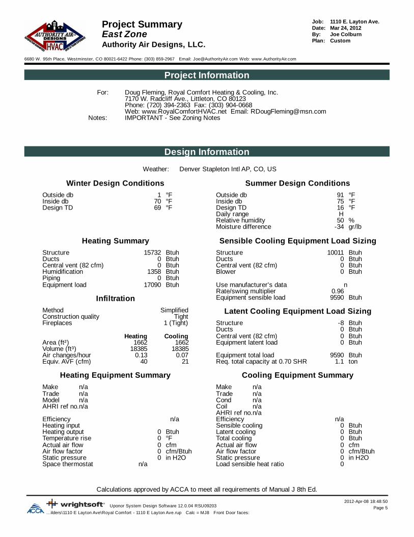
1110 E. Layton Ave.Job:Project Summary Mar 24, 2012Date:Entire House Joe ColburnBy:
CustomPlan:Authority Air Designs, LLC.
6680 W. 95th Place, Westminster, CO 80021-6422 Phone: (303) 859-2967 Email: [email protected] Web: www.AuthorityAir.com
Project Information
Doug Fleming, Royal Comfort Heating & Cooling, Inc.For:7170 W. Radcliff Ave., Littleton, CO 80123Phone: (720) 394-2363 Fax: (303) 904-0668Web: www.RoyalComfortHVAC.net Email: [email protected] - See Zoning NotesNotes:
Design Information
Denver Stapleton Intl AP, CO, USWeather:
Winter Design Conditions Summer Design Conditions
Outside db °F1 Outside db °F91Inside db °F70 Inside db °F75Design TD °F69 Design TD °F16
Daily range HRelative humidity %50Moisture difference gr/lb-34
Heating Summary Sensible Cooling Equipment Load Sizing
Structure Btuh79861 Structure Btuh39960Ducts Btuh6876 Ducts Btuh5177Central vent (419 cfm) 26208 Btuh Central vent (419 cfm) Btuh6001Humidification Btuh6657 Blower Btuh0Piping Btuh0Equipment load Btuh119602 Use manufacturer's data n
Rate/swing multiplier 0.96Infiltration Equipment sensible load Btuh48991
Method Latent Cooling Equipment Load SizingSimplifiedConstruction quality Tight
1 (Tight)Fireplaces Structure Btuh-798Ducts Btuh-52
CoolingHeating Central vent (419 cfm) Btuh-799194819481Area (ft²) Equipment latent load Btuh0
8988189881Volume (ft³)Air changes/hour 0.070.13 Equipment total load Btuh48991Equiv. AVF (cfm) 105195 Req. total capacity at 0.70 SHR ton5.8
Heating Equipment Summary Cooling Equipment Summary
Make n/a Make n/aTrade n/a Trade n/aModel n/a Cond n/aAHRI ref no.n/a Coil n/a
AHRI ref no.n/aEfficiency n/a Efficiency n/aHeating input Sensible cooling Btuh0Heating output Btuh0 Latent cooling Btuh0Temperature rise °F0 Total cooling Btuh0Actual air flow cfm0 Actual air flow cfm0Air flow factor cfm/Btuh0 Air flow factor cfm/Btuh0Static pressure in H2O0 Static pressure in H2O0Space thermostat n/a Load sensible heat ratio 0

Calculations approved by ACCA to meet all requirements of Manual J 8th Ed.
2012-Apr-08 18:48:50Uponor System Design Software 12.0.04 RSU09203 Page 2
...ilders\1110 E Layton Ave\Royal Comfort - 1110 E Layton Ave.rup Calc = MJ8 Front Door faces:
1110 E. Layton Ave.Job:Project Summary Mar 24, 2012Date:Basement Zone Joe ColburnBy:
CustomPlan:Authority Air Designs, LLC.
6680 W. 95th Place, Westminster, CO 80021-6422 Phone: (303) 859-2967 Email: [email protected] Web: www.AuthorityAir.com
Project Information
Doug Fleming, Royal Comfort Heating & Cooling, Inc.For:7170 W. Radcliff Ave., Littleton, CO 80123Phone: (720) 394-2363 Fax: (303) 904-0668Web: www.RoyalComfortHVAC.net Email: [email protected] - See Zoning NotesNotes:
Design Information
Denver Stapleton Intl AP, CO, USWeather:
Winter Design Conditions Summer Design Conditions
Outside db °F1 Outside db °F91Inside db °F70 Inside db °F75Design TD °F69 Design TD °F16
Daily range HRelative humidity %50Moisture difference gr/lb-34
Heating Summary Sensible Cooling Equipment Load Sizing
Structure Btuh22381 Structure Btuh8738Ducts Btuh0 Ducts Btuh0Central vent (153 cfm) 9534 Btuh Central vent (153 cfm) Btuh2183Humidification Btuh10552 Blower Btuh0Piping Btuh0Equipment load Btuh42467 Use manufacturer's data n
Rate/swing multiplier 0.96Infiltration Equipment sensible load Btuh10462
Method Latent Cooling Equipment Load SizingSimplifiedConstruction quality Tight
1 (Tight)Fireplaces Structure Btuh-435Ducts Btuh0
CoolingHeating Central vent (153 cfm) Btuh-290737153715Area (ft²) Equipment latent load Btuh0
3186831868Volume (ft³)Air changes/hour 0.060.12 Equipment total load Btuh10462Equiv. AVF (cfm) 3362 Req. total capacity at 0.85 SHR ton1.0
Heating Equipment Summary Cooling Equipment Summary
Make Bryant Make BryantTrade BRYANT Trade Legacy 13Model 925TA42060V17A Cond 113ANA018-BAHRI ref no.4740263 Coil CNPVP2417A
AHRI ref no.3040613Efficiency 96.3 AFUE Efficiency 11.2 EER, 13.2 SEERHeating input Btuh53664 Sensible cooling Btuh15300Heating output Btuh51875 Latent cooling Btuh2700Temperature rise °F57 Total cooling Btuh18000Actual air flow cfm1000 Actual air flow cfm1000Air flow factor cfm/Btuh0.045 Air flow factor cfm/Btuh0.114Static pressure in H2O1.00 Static pressure in H2O1.00Space thermostat Load sensible heat ratio 1.00

Calculations approved by ACCA to meet all requirements of Manual J 8th Ed.
2012-Apr-08 18:48:50Uponor System Design Software 12.0.04 RSU09203 Page 3
...ilders\1110 E Layton Ave\Royal Comfort - 1110 E Layton Ave.rup Calc = MJ8 Front Door faces:
1110 E. Layton Ave.Job:Project Summary Mar 24, 2012Date:Main Zone Joe ColburnBy:
CustomPlan:Authority Air Designs, LLC.
6680 W. 95th Place, Westminster, CO 80021-6422 Phone: (303) 859-2967 Email: [email protected] Web: www.AuthorityAir.com
Project Information
Doug Fleming, Royal Comfort Heating & Cooling, Inc.For:7170 W. Radcliff Ave., Littleton, CO 80123Phone: (720) 394-2363 Fax: (303) 904-0668Web: www.RoyalComfortHVAC.net Email: [email protected] - See Zoning NotesNotes:
Design Information
Denver Stapleton Intl AP, CO, USWeather:
Winter Design Conditions Summer Design Conditions
Outside db °F1 Outside db °F91Inside db °F70 Inside db °F75Design TD °F69 Design TD °F16
Daily range HRelative humidity %50Moisture difference gr/lb-34
Heating Summary Sensible Cooling Equipment Load Sizing
Structure Btuh36140 Structure Btuh21478Ducts Btuh0 Ducts Btuh0Central vent (184 cfm) 11476 Btuh Central vent (184 cfm) Btuh2628Humidification Btuh12922 Blower Btuh0Piping Btuh0Equipment load Btuh60537 Use manufacturer's data n
Rate/swing multiplier 0.96Infiltration Equipment sensible load Btuh23093
Method Latent Cooling Equipment Load SizingSimplifiedConstruction quality Tight
1 (Tight)Fireplaces Structure Btuh-430Ducts Btuh0
CoolingHeating Central vent (184 cfm) Btuh-349937153715Area (ft²) Equipment latent load Btuh0
3895338953Volume (ft³)Air changes/hour 0.070.12 Equipment total load Btuh23093Equiv. AVF (cfm) 4481 Req. total capacity at 0.85 SHR ton2.3
Heating Equipment Summary Cooling Equipment Summary
Make Bryant Make BryantTrade Bryant Trade Preferred Two-Stage 17Model 355CAV060080 Cond 127ANA036AHRI ref no.2010326 Coil CNPVP4821A
AHRI ref no.5104547Efficiency 95 AFUE Efficiency 12.7 EER, 16.5 SEERHeating input Btuh63360 Sensible cooling Btuh30940Heating output Btuh58608 Latent cooling Btuh5460Temperature rise °F40 Total cooling Btuh36400Actual air flow cfm1600 Actual air flow cfm1600Air flow factor cfm/Btuh0.044 Air flow factor cfm/Btuh0.073Static pressure in H2O1.00 Static pressure in H2O1.00Space thermostat Load sensible heat ratio 1.00

Calculations approved by ACCA to meet all requirements of Manual J 8th Ed.
2012-Apr-08 18:48:50Uponor System Design Software 12.0.04 RSU09203 Page 4
...ilders\1110 E Layton Ave\Royal Comfort - 1110 E Layton Ave.rup Calc = MJ8 Front Door faces:
1110 E. Layton Ave.Job:Project Summary Mar 24, 2012Date:Upper Zone Joe ColburnBy:
CustomPlan:Authority Air Designs, LLC.
6680 W. 95th Place, Westminster, CO 80021-6422 Phone: (303) 859-2967 Email: [email protected] Web: www.AuthorityAir.com
Project Information
Doug Fleming, Royal Comfort Heating & Cooling, Inc.For:7170 W. Radcliff Ave., Littleton, CO 80123Phone: (720) 394-2363 Fax: (303) 904-0668Web: www.RoyalComfortHVAC.net Email: [email protected] - See Zoning NotesNotes:
Design Information
Denver Stapleton Intl AP, CO, USWeather:
Winter Design Conditions Summer Design Conditions
Outside db °F1 Outside db °F91Inside db °F70 Inside db °F75Design TD °F69 Design TD °F16
Daily range HRelative humidity %50Moisture difference gr/lb-34
Heating Summary Sensible Cooling Equipment Load Sizing
Structure Btuh21340 Structure Btuh10306Ducts Btuh6876 Ducts Btuh5293Central vent (83 cfm) 5198 Btuh Central vent (83 cfm) Btuh1190Humidification Btuh6377 Blower Btuh0Piping Btuh0Equipment load Btuh39791 Use manufacturer's data n
Rate/swing multiplier 0.96Infiltration Equipment sensible load Btuh16084
Method Latent Cooling Equipment Load SizingSimplifiedConstruction quality Tight
1 (Tight)Fireplaces Structure Btuh67Ducts Btuh-52
CoolingHeating Central vent (83 cfm) Btuh-158520502050Area (ft²) Equipment latent load Btuh0
1906019060Volume (ft³)Air changes/hour 0.090.16 Equipment total load Btuh16084Equiv. AVF (cfm) 2852 Req. total capacity at 0.85 SHR ton1.6
Heating Equipment Summary Cooling Equipment Summary
Make Bryant Make BryantTrade Bryant Trade 13 SeerModel 925TA42060V17A Cond 113ANA024AHRI ref no.4740263 Coil CNPHP3017A
AHRI ref no.4765618Efficiency 96.3 AFUE Efficiency 12.0 EER, 14.5 SEERHeating input Btuh53664 Sensible cooling Btuh19720Heating output Btuh51875 Latent cooling Btuh3480Temperature rise °F57 Total cooling Btuh23200Actual air flow cfm1000 Actual air flow cfm1000Air flow factor cfm/Btuh0.035 Air flow factor cfm/Btuh0.064Static pressure in H2O1.00 Static pressure in H2O1.00Space thermostat Load sensible heat ratio 1.00
Calculations approved by ACCA to meet all requirements of Manual J 8th Ed.
2012-Apr-08 18:48:50Uponor System Design Software 12.0.04 RSU09203 Page 5
...ilders\1110 E Layton Ave\Royal Comfort - 1110 E Layton Ave.rup Calc = MJ8 Front Door faces:
1110 E. Layton Ave.Job:Project Summary Mar 24, 2012Date:East Zone Joe ColburnBy:
CustomPlan:Authority Air Designs, LLC.
6680 W. 95th Place, Westminster, CO 80021-6422 Phone: (303) 859-2967 Email: [email protected] Web: www.AuthorityAir.com
Project Information
Doug Fleming, Royal Comfort Heating & Cooling, Inc.For:7170 W. Radcliff Ave., Littleton, CO 80123Phone: (720) 394-2363 Fax: (303) 904-0668Web: www.RoyalComfortHVAC.net Email: [email protected] - See Zoning NotesNotes:
Design Information
Denver Stapleton Intl AP, CO, USWeather:
Winter Design Conditions Summer Design Conditions
Outside db °F1 Outside db °F91Inside db °F70 Inside db °F75Design TD °F69 Design TD °F16
Daily range HRelative humidity %50Moisture difference gr/lb-34
Heating Summary Sensible Cooling Equipment Load Sizing
Structure Btuh15732 Structure Btuh10011Ducts Btuh0 Ducts Btuh0Central vent (82 cfm) 0 Btuh Central vent (82 cfm) Btuh0Humidification Btuh1358 Blower Btuh0Piping Btuh0Equipment load Btuh17090 Use manufacturer's data n
Rate/swing multiplier 0.96Infiltration Equipment sensible load Btuh9590
Method Latent Cooling Equipment Load SizingSimplifiedConstruction quality Tight
1 (Tight)Fireplaces Structure Btuh-8Ducts Btuh0
CoolingHeating Central vent (82 cfm) Btuh016621662Area (ft²) Equipment latent load Btuh0
1838518385Volume (ft³)Air changes/hour 0.070.13 Equipment total load Btuh9590Equiv. AVF (cfm) 2140 Req. total capacity at 0.70 SHR ton1.1
Heating Equipment Summary Cooling Equipment Summary
Make n/a Make n/aTrade n/a Trade n/aModel n/a Cond n/aAHRI ref no.n/a Coil n/a
AHRI ref no.n/aEfficiency n/a Efficiency n/aHeating input Sensible cooling Btuh0Heating output Btuh0 Latent cooling Btuh0Temperature rise °F0 Total cooling Btuh0Actual air flow cfm0 Actual air flow cfm0Air flow factor cfm/Btuh0 Air flow factor cfm/Btuh0Static pressure in H2O0 Static pressure in H2O0Space thermostat n/a Load sensible heat ratio 0

Calculations approved by ACCA to meet all requirements of Manual J 8th Ed.
2012-Apr-08 18:48:50Uponor System Design Software 12.0.04 RSU09203 Page 6
...ilders\1110 E Layton Ave\Royal Comfort - 1110 E Layton Ave.rup Calc = MJ8 Front Door faces:
1110 E. Layton Ave.Job:Project Summary Mar 24, 2012Date:West Zone Joe ColburnBy:
CustomPlan:Authority Air Designs, LLC.
6680 W. 95th Place, Westminster, CO 80021-6422 Phone: (303) 859-2967 Email: [email protected] Web: www.AuthorityAir.com
Project Information
Doug Fleming, Royal Comfort Heating & Cooling, Inc.For:7170 W. Radcliff Ave., Littleton, CO 80123Phone: (720) 394-2363 Fax: (303) 904-0668Web: www.RoyalComfortHVAC.net Email: [email protected] - See Zoning NotesNotes:
Design Information
Denver Stapleton Intl AP, CO, USWeather:
Winter Design Conditions Summer Design Conditions
Outside db °F1 Outside db °F91Inside db °F70 Inside db °F75Design TD °F69 Design TD °F16
Daily range HRelative humidity %50Moisture difference gr/lb-34
Heating Summary Sensible Cooling Equipment Load Sizing
Structure Btuh20408 Structure Btuh17291Ducts Btuh0 Ducts Btuh0Central vent (102 cfm) 0 Btuh Central vent (102 cfm) Btuh0Humidification Btuh1407 Blower Btuh0Piping Btuh0Equipment load Btuh21816 Use manufacturer's data n
Rate/swing multiplier 0.96Infiltration Equipment sensible load Btuh16565
Method Latent Cooling Equipment Load SizingSimplifiedConstruction quality Tight
1 (Tight)Fireplaces Structure Btuh-422Ducts Btuh0
CoolingHeating Central vent (102 cfm) Btuh020532053Area (ft²) Equipment latent load Btuh0
2056820568Volume (ft³)Air changes/hour 0.060.12 Equipment total load Btuh16565Equiv. AVF (cfm) 2241 Req. total capacity at 0.70 SHR ton2.0
Heating Equipment Summary Cooling Equipment Summary
Make n/a Make n/aTrade n/a Trade n/aModel n/a Cond n/aAHRI ref no.n/a Coil n/a
AHRI ref no.n/aEfficiency n/a Efficiency n/aHeating input Sensible cooling Btuh0Heating output Btuh0 Latent cooling Btuh0Temperature rise °F0 Total cooling Btuh0Actual air flow cfm0 Actual air flow cfm0Air flow factor cfm/Btuh0 Air flow factor cfm/Btuh0Static pressure in H2O0 Static pressure in H2O0Space thermostat n/a Load sensible heat ratio 0

2012-Apr-08 18:48:50Uponor System Design Software 12.0.04 RSU09203 Page 1
...ilders\1110 E Layton Ave\Royal Comfort - 1110 E Layton Ave.rup Calc = MJ8 Front Door faces:
1110 E. Layton Ave.Job:AED Assessment Mar 24, 2012Date:
Entire House Joe ColburnBy:CustomPlan:
Authority Air Designs, LLC.
6680 W. 95th Place, Westminster, CO 80021-6422 Phone: (303) 859-2967 Email: [email protected] Web: www.AuthorityAir.com
Project InformationDoug Fleming, Royal Comfort Heating & Cooling, Inc.For:7170 W. Radcliff Ave., Littleton, CO 80123Phone: (720) 394-2363 Fax: (303) 904-0668Web: www.RoyalComfortHVAC.net Email: [email protected]
Design ConditionsLocation: CoolingHeatingIndoor:
7570Indoor temperature (°F)Denver Stapleton Intl AP, CO, US1669Design TD (°F)ft5285Elevation:5050Relative humidity (%)°N40Latitude:
Outdoor: -34.061.1Moisture difference (gr/lb)CoolingHeatingInfiltration:911Dry bulb (°F)
)H(27-Daily range (°F)60-Wet bulb (°F)7.515.0Wind speed (mph)
Test for Adequate Exposure Diversity
Hourly Glazing Load
Hourly Average AED limit
Gla
zing
load
(B
tuh)
Hour of Day
0
2,000
4,000
6,000
8,000
10,000
12,000
14,000
16,000
18,000
20,000
22,000
24,000
26,000
28,000
8 9 10 11 12 13 14 15 16 17 18 19 20
Maximum hourly glazing load exceeds average by 30.0%.
House does not have adequate exposure diversity (AED), based on AED limit of 30%.
AED excursion: 6 Btuh (PFG - 1.3*AFG)
2012-Apr-08 18:48:50Uponor System Design Software 12.0.04 RSU09203 Page 2
...ilders\1110 E Layton Ave\Royal Comfort - 1110 E Layton Ave.rup Calc = MJ8 Front Door faces:
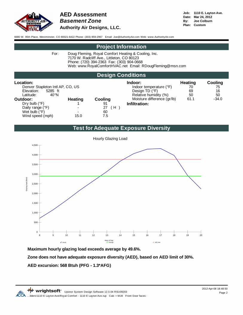
1110 E. Layton Ave.Job:AED Assessment Mar 24, 2012Date:
Basement Zone Joe ColburnBy:CustomPlan:
Authority Air Designs, LLC.
6680 W. 95th Place, Westminster, CO 80021-6422 Phone: (303) 859-2967 Email: [email protected] Web: www.AuthorityAir.com
Project InformationDoug Fleming, Royal Comfort Heating & Cooling, Inc.For:7170 W. Radcliff Ave., Littleton, CO 80123Phone: (720) 394-2363 Fax: (303) 904-0668Web: www.RoyalComfortHVAC.net Email: [email protected]
Design ConditionsLocation: CoolingHeatingIndoor:
7570Indoor temperature (°F)Denver Stapleton Intl AP, CO, US1669Design TD (°F)ft5285Elevation:5050Relative humidity (%)°N40Latitude:
Outdoor: -34.061.1Moisture difference (gr/lb)CoolingHeatingInfiltration:911Dry bulb (°F)
)H(27-Daily range (°F)60-Wet bulb (°F)7.515.0Wind speed (mph)
Test for Adequate Exposure Diversity
Hourly Glazing Load
Hourly Average AED limit
Gla
zing
load
(B
tuh)
Hour of Day
0
500
1,000
1,500
2,000
2,500
3,000
3,500
4,000
4,500
8 9 10 11 12 13 14 15 16 17 18 19 20
Maximum hourly glazing load exceeds average by 49.6%.
Zone does not have adequate exposure diversity (AED), based on AED limit of 30%.
AED excursion: 568 Btuh (PFG - 1.3*AFG)
2012-Apr-08 18:48:50Uponor System Design Software 12.0.04 RSU09203 Page 3
...ilders\1110 E Layton Ave\Royal Comfort - 1110 E Layton Ave.rup Calc = MJ8 Front Door faces:
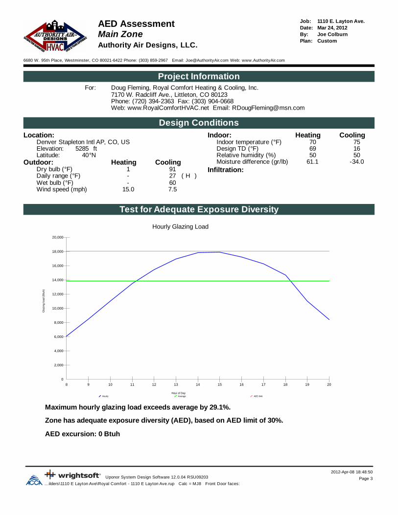
1110 E. Layton Ave.Job:AED Assessment Mar 24, 2012Date:
Main Zone Joe ColburnBy:CustomPlan:
Authority Air Designs, LLC.
6680 W. 95th Place, Westminster, CO 80021-6422 Phone: (303) 859-2967 Email: [email protected] Web: www.AuthorityAir.com
Project InformationDoug Fleming, Royal Comfort Heating & Cooling, Inc.For:7170 W. Radcliff Ave., Littleton, CO 80123Phone: (720) 394-2363 Fax: (303) 904-0668Web: www.RoyalComfortHVAC.net Email: [email protected]
Design ConditionsLocation: CoolingHeatingIndoor:
7570Indoor temperature (°F)Denver Stapleton Intl AP, CO, US1669Design TD (°F)ft5285Elevation:5050Relative humidity (%)°N40Latitude:
Outdoor: -34.061.1Moisture difference (gr/lb)CoolingHeatingInfiltration:911Dry bulb (°F)
)H(27-Daily range (°F)60-Wet bulb (°F)7.515.0Wind speed (mph)
Test for Adequate Exposure Diversity
Hourly Glazing Load
Hourly Average AED limit
Gla
zing
load
(B
tuh)
Hour of Day
0
2,000
4,000
6,000
8,000
10,000
12,000
14,000
16,000
18,000
20,000
8 9 10 11 12 13 14 15 16 17 18 19 20
Maximum hourly glazing load exceeds average by 29.1%.
Zone has adequate exposure diversity (AED), based on AED limit of 30%.
AED excursion: 0 Btuh

2012-Apr-08 18:48:50Uponor System Design Software 12.0.04 RSU09203 Page 4
...ilders\1110 E Layton Ave\Royal Comfort - 1110 E Layton Ave.rup Calc = MJ8 Front Door faces:
1110 E. Layton Ave.Job:AED Assessment Mar 24, 2012Date:
Upper Zone Joe ColburnBy:CustomPlan:
Authority Air Designs, LLC.
6680 W. 95th Place, Westminster, CO 80021-6422 Phone: (303) 859-2967 Email: [email protected] Web: www.AuthorityAir.com
Project InformationDoug Fleming, Royal Comfort Heating & Cooling, Inc.For:7170 W. Radcliff Ave., Littleton, CO 80123Phone: (720) 394-2363 Fax: (303) 904-0668Web: www.RoyalComfortHVAC.net Email: [email protected]
Design ConditionsLocation: CoolingHeatingIndoor:
7570Indoor temperature (°F)Denver Stapleton Intl AP, CO, US1669Design TD (°F)ft5285Elevation:5050Relative humidity (%)°N40Latitude:
Outdoor: -34.061.1Moisture difference (gr/lb)CoolingHeatingInfiltration:911Dry bulb (°F)
)H(27-Daily range (°F)60-Wet bulb (°F)7.515.0Wind speed (mph)
Test for Adequate Exposure Diversity
Hourly Glazing Load
Hourly Average AED limit
Gla
zing
load
(B
tuh)
Hour of Day
0
500
1,000
1,500
2,000
2,500
3,000
3,500
4,000
4,500
5,000
5,500
6,000
8 9 10 11 12 13 14 15 16 17 18 19 20
Maximum hourly glazing load exceeds average by 26.6%.
Zone has adequate exposure diversity (AED), based on AED limit of 30%.
AED excursion: 0 Btuh
2012-Apr-08 18:48:50Uponor System Design Software 12.0.04 RSU09203 Page 5
...ilders\1110 E Layton Ave\Royal Comfort - 1110 E Layton Ave.rup Calc = MJ8 Front Door faces:
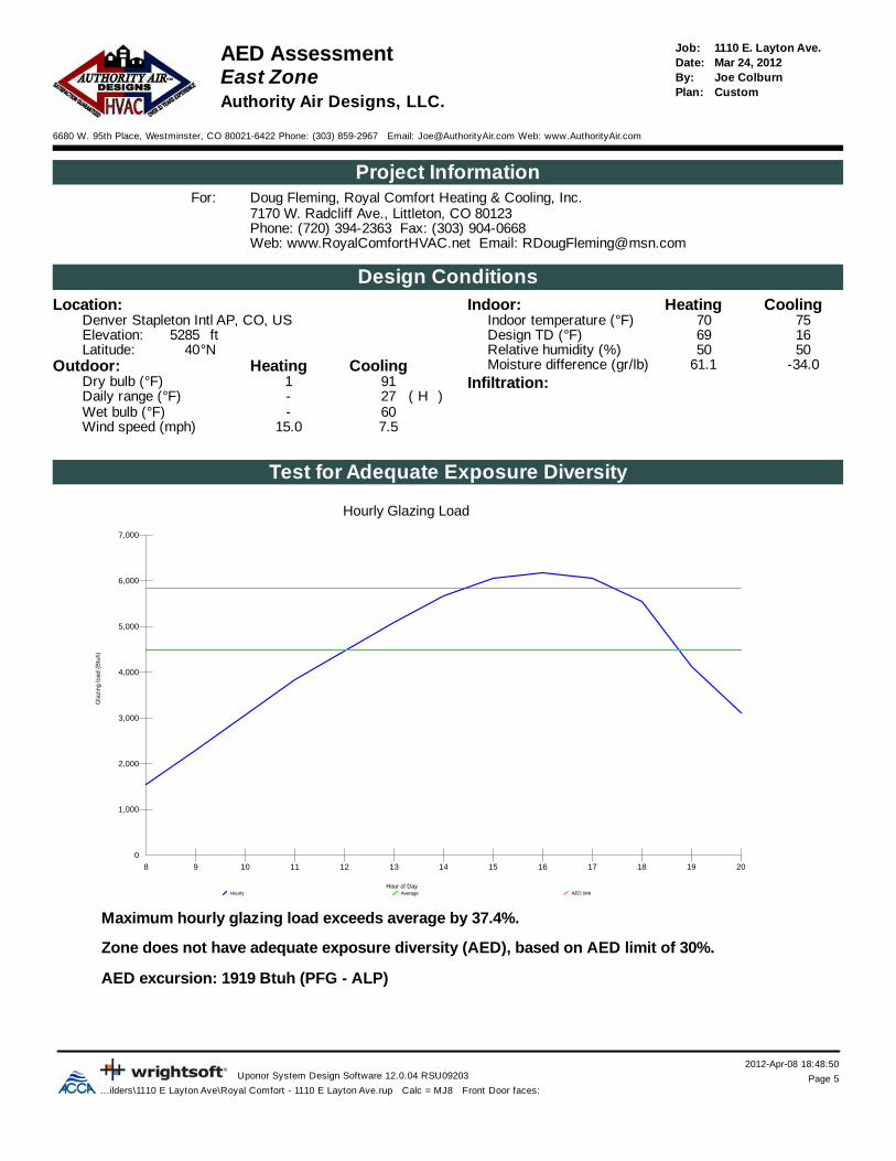
1110 E. Layton Ave.Job:AED Assessment Mar 24, 2012Date:
East Zone Joe ColburnBy:CustomPlan:
Authority Air Designs, LLC.
6680 W. 95th Place, Westminster, CO 80021-6422 Phone: (303) 859-2967 Email: [email protected] Web: www.AuthorityAir.com
Project InformationDoug Fleming, Royal Comfort Heating & Cooling, Inc.For:7170 W. Radcliff Ave., Littleton, CO 80123Phone: (720) 394-2363 Fax: (303) 904-0668Web: www.RoyalComfortHVAC.net Email: [email protected]
Design ConditionsLocation: CoolingHeatingIndoor:
7570Indoor temperature (°F)Denver Stapleton Intl AP, CO, US1669Design TD (°F)ft5285Elevation:5050Relative humidity (%)°N40Latitude:
Outdoor: -34.061.1Moisture difference (gr/lb)CoolingHeatingInfiltration:911Dry bulb (°F)
)H(27-Daily range (°F)60-Wet bulb (°F)7.515.0Wind speed (mph)
Test for Adequate Exposure Diversity
Hourly Glazing Load
Hourly Average AED limit
Gla
zing
load
(B
tuh)
Hour of Day
0
1,000
2,000
3,000
4,000
5,000
6,000
7,000
8 9 10 11 12 13 14 15 16 17 18 19 20
Maximum hourly glazing load exceeds average by 37.4%.
Zone does not have adequate exposure diversity (AED), based on AED limit of 30%.
AED excursion: 1919 Btuh (PFG - ALP)

2012-Apr-08 18:48:50Uponor System Design Software 12.0.04 RSU09203 Page 6
...ilders\1110 E Layton Ave\Royal Comfort - 1110 E Layton Ave.rup Calc = MJ8 Front Door faces:
1110 E. Layton Ave.Job:AED Assessment Mar 24, 2012Date:
West Zone Joe ColburnBy:CustomPlan:
Authority Air Designs, LLC.
6680 W. 95th Place, Westminster, CO 80021-6422 Phone: (303) 859-2967 Email: [email protected] Web: www.AuthorityAir.com
Project InformationDoug Fleming, Royal Comfort Heating & Cooling, Inc.For:7170 W. Radcliff Ave., Littleton, CO 80123Phone: (720) 394-2363 Fax: (303) 904-0668Web: www.RoyalComfortHVAC.net Email: [email protected]
Design ConditionsLocation: CoolingHeatingIndoor:
7570Indoor temperature (°F)Denver Stapleton Intl AP, CO, US1669Design TD (°F)ft5285Elevation:5050Relative humidity (%)°N40Latitude:
Outdoor: -34.061.1Moisture difference (gr/lb)CoolingHeatingInfiltration:911Dry bulb (°F)
)H(27-Daily range (°F)60-Wet bulb (°F)7.515.0Wind speed (mph)
Test for Adequate Exposure Diversity
Hourly Glazing Load
Hourly Average AED limit
Gla
zing
load
(B
tuh)
Hour of Day
0
2,000
4,000
6,000
8,000
10,000
12,000
14,000
8 9 10 11 12 13 14 15 16 17 18 19 20
Maximum hourly glazing load exceeds average by 29.5%.
Zone has adequate exposure diversity (AED), based on AED limit of 30%.
AED excursion: 3905 Btuh (PFG - ALP)

2012-Apr-08 18:48:51Uponor System Design Software 12.0.04 RSU09203 Page 1
...ilders\1110 E Layton Ave\Royal Comfort - 1110 E Layton Ave.rup Calc = MJ8 Front Door faces:
1110 E. Layton Ave.Job:Building Analysis Mar 24, 2012Date:
Entire House Joe ColburnBy:CustomPlan:
Authority Air Designs, LLC.
6680 W. 95th Place, Westminster, CO 80021-6422 Phone: (303) 859-2967 Email: [email protected] Web: www.AuthorityAir.com
Project InformationDoug Fleming, Royal Comfort Heating & Cooling, Inc.For:7170 W. Radcliff Ave., Littleton, CO 80123Phone: (720) 394-2363 Fax: (303) 904-0668Web: www.RoyalComfortHVAC.net Email: [email protected]
Design ConditionsLocation: CoolingHeatingIndoor:
7570Indoor temperature (°F)Denver Stapleton Intl AP, CO, US1669Design TD (°F)ft5285Elevation:5050Relative humidity (%)°N40Latitude:
Outdoor: -34.061.1Moisture difference (gr/lb)CoolingHeatingInfiltration:911Dry bulb (°F)
SimplifiedMethod)H(27-Daily range (°F)TightConstruction quality60-Wet bulb (°F)1 (Tight)Fireplaces7.515.0Wind speed (mph)
Heating
Walls
Glazing
OtherCeilings
Floors
Infiltration
Ducts
Ventilation
Humidification% of loadBtuhBtuh/ft²Component
26.9322054.1Walls18.62223920.7Glazing0.896226.9Doors5.970431.8Ceilings4.452441.41.4Floors
10.2121681.4Infiltration5.76876Ducts
00Piping5.66657Humidification
21.926208Ventilation0Adjustments
100.0119602Total
Cooling
Walls
GlazingOther
Ceilings
Infiltration
Ducts
Internal Gains
Ventilation
% of loadBtuhBtuh/ft²Component
20.4104071.3Walls38.21953618.2Glazing0.63299.2Doors9.448081.3Ceilings
000Floors2.915000.2Infiltration
10.15177Ducts11.76001Ventilation6.63380Internal gains
00Blower0Adjustments
100.051138Total
Latent Cooling Load = 0 BtuhOverall U-value = 0.059 Btuh/ft²-°F
Data entries checked.

2012-Apr-08 18:48:51Uponor System Design Software 12.0.04 RSU09203 Page 2
...ilders\1110 E Layton Ave\Royal Comfort - 1110 E Layton Ave.rup Calc = MJ8 Front Door faces:
1110 E. Layton Ave.Job:Building Analysis Mar 24, 2012Date:
Basement Zone Joe ColburnBy:CustomPlan:
Authority Air Designs, LLC.
6680 W. 95th Place, Westminster, CO 80021-6422 Phone: (303) 859-2967 Email: [email protected] Web: www.AuthorityAir.com
Project InformationDoug Fleming, Royal Comfort Heating & Cooling, Inc.For:7170 W. Radcliff Ave., Littleton, CO 80123Phone: (720) 394-2363 Fax: (303) 904-0668Web: www.RoyalComfortHVAC.net Email: [email protected]
Design ConditionsLocation: CoolingHeatingIndoor:
7570Indoor temperature (°F)Denver Stapleton Intl AP, CO, US1669Design TD (°F)ft5285Elevation:5050Relative humidity (%)°N40Latitude:
Outdoor: -34.061.1Moisture difference (gr/lb)CoolingHeatingInfiltration:911Dry bulb (°F)
SimplifiedMethod)H(27-Daily range (°F)TightConstruction quality60-Wet bulb (°F)1 (Tight)Fireplaces7.515.0Wind speed (mph)
Heating
Walls
Glazing
Other
Floors
Infiltration
Ventilation
Humidification
% of loadBtuhBtuh/ft²Component
24.8105333.9Walls6.5277720.7Glazing
000Doors0.2781.8Ceilings
12.151271.41.4Floors9.138651.4Infiltration
00Ducts00Piping
24.810552Humidification22.49534Ventilation
0Adjustments100.042467Total
Cooling
Walls
Glazing
Other
Infiltration
Internal Gains
Ventilation
% of loadBtuhBtuh/ft²Component
41.845651.7Walls31.2341325.4Glazing
000Doors0.5531.3Ceilings
000Floors4.44770.2Infiltration
00Ducts20.02183Ventilation2.1230Internal gains
00Blower0Adjustments
100.010921Total
Latent Cooling Load = 0 BtuhOverall U-value = 0.041 Btuh/ft²-°F
WARNING: window to floor area ratio = 3.6% - less than 5%.

2012-Apr-08 18:48:51Uponor System Design Software 12.0.04 RSU09203 Page 3
...ilders\1110 E Layton Ave\Royal Comfort - 1110 E Layton Ave.rup Calc = MJ8 Front Door faces:
1110 E. Layton Ave.Job:Building Analysis Mar 24, 2012Date:
Main Zone Joe ColburnBy:CustomPlan:
Authority Air Designs, LLC.
6680 W. 95th Place, Westminster, CO 80021-6422 Phone: (303) 859-2967 Email: [email protected] Web: www.AuthorityAir.com
Project InformationDoug Fleming, Royal Comfort Heating & Cooling, Inc.For:7170 W. Radcliff Ave., Littleton, CO 80123Phone: (720) 394-2363 Fax: (303) 904-0668Web: www.RoyalComfortHVAC.net Email: [email protected]
Design ConditionsLocation: CoolingHeatingIndoor:
7570Indoor temperature (°F)Denver Stapleton Intl AP, CO, US1669Design TD (°F)ft5285Elevation:5050Relative humidity (%)°N40Latitude:
Outdoor: -34.061.1Moisture difference (gr/lb)CoolingHeatingInfiltration:911Dry bulb (°F)
SimplifiedMethod)H(27-Daily range (°F)TightConstruction quality60-Wet bulb (°F)1 (Tight)Fireplaces7.515.0Wind speed (mph)
Heating
Walls
Glazing
OtherCeilings
Infiltration
Ventilation
Humidification
% of loadBtuhBtuh/ft²Component
20.9126344.2Walls23.61431420.7Glazing1.696226.9Doors5.231761.8Ceilings
0000Floors8.450551.4Infiltration
00Ducts00Piping
21.312922Humidification19.011476Ventilation
0Adjustments100.060537Total
Cooling
Walls
Glazing
Other
Ceilings
Infiltration
Internal Gains
Ventilation
% of loadBtuhBtuh/ft²Component
14.134061.1Walls51.81249218.1Glazing1.43299.2Doors9.021681.3Ceilings
000Floors2.66230.2Infiltration
00Ducts10.92628Ventilation10.22460Internal gains
00Blower0Adjustments
100.024106Total
Latent Cooling Load = 0 BtuhOverall U-value = 0.083 Btuh/ft²-°F
Data entries checked.

2012-Apr-08 18:48:51Uponor System Design Software 12.0.04 RSU09203 Page 4
...ilders\1110 E Layton Ave\Royal Comfort - 1110 E Layton Ave.rup Calc = MJ8 Front Door faces:
1110 E. Layton Ave.Job:Building Analysis Mar 24, 2012Date:
Upper Zone Joe ColburnBy:CustomPlan:
Authority Air Designs, LLC.
6680 W. 95th Place, Westminster, CO 80021-6422 Phone: (303) 859-2967 Email: [email protected] Web: www.AuthorityAir.com
Project InformationDoug Fleming, Royal Comfort Heating & Cooling, Inc.For:7170 W. Radcliff Ave., Littleton, CO 80123Phone: (720) 394-2363 Fax: (303) 904-0668Web: www.RoyalComfortHVAC.net Email: [email protected]
Design ConditionsLocation: CoolingHeatingIndoor:
7570Indoor temperature (°F)Denver Stapleton Intl AP, CO, US1669Design TD (°F)ft5285Elevation:5050Relative humidity (%)°N40Latitude:
Outdoor: -34.061.1Moisture difference (gr/lb)CoolingHeatingInfiltration:911Dry bulb (°F)
SimplifiedMethod)H(27-Daily range (°F)TightConstruction quality60-Wet bulb (°F)1 (Tight)Fireplaces7.515.0Wind speed (mph)
Heating
Walls
Glazing
Ceilings
OtherInfiltration
Ducts
Ventilation
Humidification
% of loadBtuhBtuh/ft²Component
22.790394.2Walls12.9514820.7Glazing
000Doors9.537891.8Ceilings0.31172.02.0Floors8.232481.4Infiltration
17.36876Ducts00Piping
16.06377Humidification13.15198Ventilation
0Adjustments100.039791Total
Cooling
Walls
Glazing
CeilingsInfiltration
Ducts
Internal Gains
Ventilation% of loadBtuhBtuh/ft²Component
14.524361.1Walls25.0419316.9Glazing
000Doors15.425861.3Ceilings
000Floors2.44000.2Infiltration
31.55293Ducts7.11190Ventilation4.1690Internal gains
00Blower0Adjustments
100.016790Total
Latent Cooling Load = 0 BtuhOverall U-value = 0.058 Btuh/ft²-°F
Data entries checked.
2012-Apr-08 18:48:51Uponor System Design Software 12.0.04 RSU09203 Page 5
...ilders\1110 E Layton Ave\Royal Comfort - 1110 E Layton Ave.rup Calc = MJ8 Front Door faces:
1110 E. Layton Ave.Job:Building Analysis Mar 24, 2012Date:
East Zone Joe ColburnBy:CustomPlan:
Authority Air Designs, LLC.
6680 W. 95th Place, Westminster, CO 80021-6422 Phone: (303) 859-2967 Email: [email protected] Web: www.AuthorityAir.com
Project InformationDoug Fleming, Royal Comfort Heating & Cooling, Inc.For:7170 W. Radcliff Ave., Littleton, CO 80123Phone: (720) 394-2363 Fax: (303) 904-0668Web: www.RoyalComfortHVAC.net Email: [email protected]
Design ConditionsLocation: CoolingHeatingIndoor:
7570Indoor temperature (°F)Denver Stapleton Intl AP, CO, US1669Design TD (°F)ft5285Elevation:5050Relative humidity (%)°N40Latitude:
Outdoor: -34.061.1Moisture difference (gr/lb)CoolingHeatingInfiltration:911Dry bulb (°F)
SimplifiedMethod)H(27-Daily range (°F)TightConstruction quality60-Wet bulb (°F)1 (Tight)Fireplaces7.515.0Wind speed (mph)
Heating
Walls
Glazing
Ceilings
Infiltration
Humidification% of loadBtuhBtuh/ft²Component
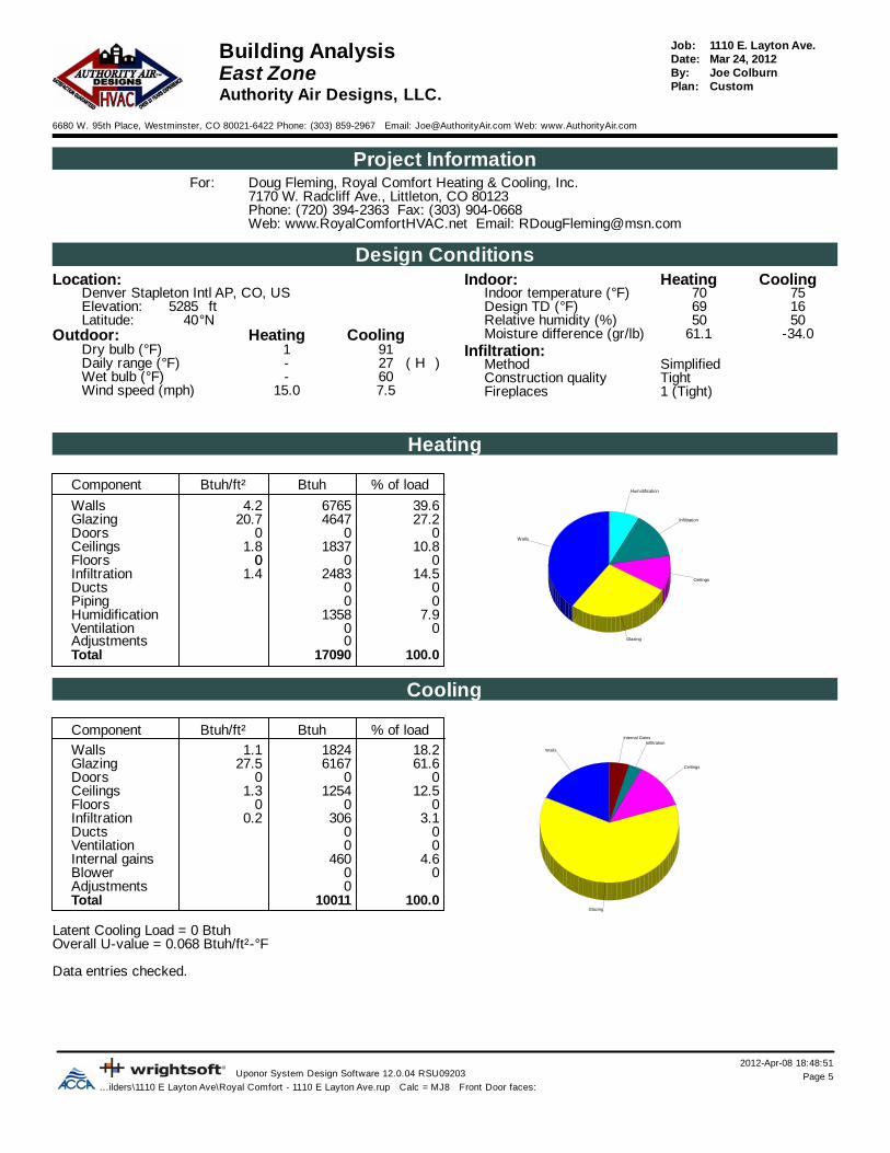
39.667654.2Walls27.2464720.7Glazing
000Doors10.818371.8Ceilings
0000Floors14.524831.4Infiltration
00Ducts00Piping
7.91358Humidification00Ventilation
0Adjustments100.017090Total
Cooling
Walls
Glazing
Ceilings
InfiltrationInternal Gains
% of loadBtuhBtuh/ft²Component
18.218241.1Walls61.6616727.5Glazing
000Doors12.512541.3Ceilings
000Floors3.13060.2Infiltration
00Ducts00Ventilation
4.6460Internal gains00Blower
0Adjustments100.010011Total
Latent Cooling Load = 0 BtuhOverall U-value = 0.068 Btuh/ft²-°F
Data entries checked.

2012-Apr-08 18:48:51Uponor System Design Software 12.0.04 RSU09203 Page 6
...ilders\1110 E Layton Ave\Royal Comfort - 1110 E Layton Ave.rup Calc = MJ8 Front Door faces:
1110 E. Layton Ave.Job:Building Analysis Mar 24, 2012Date:
West Zone Joe ColburnBy:CustomPlan:
Authority Air Designs, LLC.
6680 W. 95th Place, Westminster, CO 80021-6422 Phone: (303) 859-2967 Email: [email protected] Web: www.AuthorityAir.com
Project InformationDoug Fleming, Royal Comfort Heating & Cooling, Inc.For:7170 W. Radcliff Ave., Littleton, CO 80123Phone: (720) 394-2363 Fax: (303) 904-0668Web: www.RoyalComfortHVAC.net Email: [email protected]
Design ConditionsLocation: CoolingHeatingIndoor:
7570Indoor temperature (°F)Denver Stapleton Intl AP, CO, US1669Design TD (°F)ft5285Elevation:5050Relative humidity (%)°N40Latitude:
Outdoor: -34.061.1Moisture difference (gr/lb)CoolingHeatingInfiltration:911Dry bulb (°F)
SimplifiedMethod)H(27-Daily range (°F)TightConstruction quality60-Wet bulb (°F)1 (Tight)Fireplaces7.515.0Wind speed (mph)
Heating
Walls
Glazing
Doors
Ceilings
Infiltration
Humidification% of loadBtuhBtuh/ft²Component
26.958694.2Walls44.3966720.7Glazing4.496226.9Doors6.113381.8Ceilings
0000Floors11.825721.4Infiltration
00Ducts00Piping
6.51407Humidification00Ventilation
0Adjustments100.021816Total
Cooling
Walls
Glazing
Other
Ceilings
Internal Gains
% of loadBtuhBtuh/ft²Component
9.115821.1Walls70.31214926.0Glazing1.93299.2Doors5.39141.3Ceilings
000Floors1.83170.2Infiltration
00Ducts00Ventilation
11.62000Internal gains00Blower
0Adjustments100.017291Total
Latent Cooling Load = 0 BtuhOverall U-value = 0.099 Btuh/ft²-°F
Data entries checked.

2012-Apr-08 18:48:51Uponor System Design Software 12.0.04 RSU09203 Page 1
...ilders\1110 E Layton Ave\Royal Comfort - 1110 E Layton Ave.rup Calc = MJ8 Front Door faces:
1110 E. Layton Ave.Job:Component Constructions Mar 24, 2012Date:Entire House Joe ColburnBy:
CustomPlan:Authority Air Designs, LLC.
6680 W. 95th Place, Westminster, CO 80021-6422 Phone: (303) 859-2967 Email: [email protected] Web: www.AuthorityAir.com
Project InformationDoug Fleming, Royal Comfort Heating & Cooling, Inc.For:7170 W. Radcliff Ave., Littleton, CO 80123Phone: (720) 394-2363 Fax: (303) 904-0668Web: www.RoyalComfortHVAC.net Email: [email protected]
Design ConditionsLocation: CoolingHeatingIndoor:
7570Indoor temperature (°F)Denver Stapleton Intl AP, CO, US1669Design TD (°F)ft5285Elevation:5050Relative humidity (%)°N40Latitude:
Outdoor: -34.061.1Moisture difference (gr/lb)CoolingHeatingInfiltration:911Dry bulb (°F)
SimplifiedMethod)H(27-Daily range (°F)TightConstruction quality60-Wet bulb (°F)1 (Tight)Fireplaces7.515.0Wind speed (mph)
Construction descriptions GainLoss Clg HTMHtg HTMInsul RU-valueAreaOrBtuhBtuh/ft²BtuhBtuh/ft²ft²-°F/BtuhBtuh/ft²-°Fft²
WallsSTD - Basement Wall - R-11 - Draped: Heavy Damp Soil, 8" BasementConcrete Wall, R-11 Draped Insulation
1831.454453.5111.00.051127n2241.455423.5111.00.051154e1831.454453.5111.00.051127s621.451513.5111.00.05143w
6531.4515823.5111.00.051451allSTD - Basement Wall - R-13 - Frame: Basement Wall, Heavy Damp Soil, 8" Concrete, 2" x 4" Framing, R-13 Cavity Insulation, 1/2" Gypsum Board
10861.7324853.9613.00.057628n1021.732333.9613.00.05759ne5181.7311853.9613.00.057299e551.731263.9613.00.05732se
10961.7325083.9613.00.057633s561.731283.9613.00.05732sw
8971.7320533.9613.00.057518w1021.732333.9613.00.05759nw
39121.7389513.9613.00.0572260allSTD - Frame - R-21 - Stucco: Wood Framed Wall, Stucco Exterior, 1/2" Sheathing, R-21 Cavity Insulation, 1/2" Gypsum Board
14101.1452304.2221.00.0611239n861.143204.2221.00.06176ne
12561.1446594.2221.00.0611104e1551.145754.2221.00.061136se
13531.1450204.2221.00.0611190s601.142214.2221.00.06152sw
14361.1453264.2221.00.0611262w861.143204.2221.00.06176nw
58421.14216724.2221.00.0615136all
Partitions(none)

Windows
2012-Apr-08 18:48:51Uponor System Design Software 12.0.04 RSU09203 Page 2
...ilders\1110 E Layton Ave\Royal Comfort - 1110 E Layton Ave.rup Calc = MJ8 Front Door faces:
U-30 SHGC-27: U-30 SHGC-27 - Windows; NFRC rated (SHGC=0.27)
20.700.30022n 2169.9744914429.97299620.700.300145n90421.586920.700.30042ne
176130.2120620.700.30058e26026.020720.700.30010se84015.8110420.700.30053s
228515.8300220.700.300145s58526.046620.700.30023sw
178830.2122520.700.30059w297730.2203920.700.30099w90421.586920.700.30042nw
1396320.01443120.700.300697allU-30 SHGC-27 GD: U-30 SHGC-27 - Glass Door; NFRC rated (SHGC=0.27)
300620.700.300145n 14479.9772530.249720.700.30024e
176515.8231820.700.300112s393714.0582120.700.300281all
U-30 SHGC-27 SLG: U-30 SHGC-30 - SLG Door; NFRC rated (SHGC=0.30)
198720.700.30096s 163017.0
Doors11D0: Door, wd sc type 1649.2048126.900.39018n
1649.2048126.900.39018e3299.2096226.900.39036all
CeilingsSTD - Attic CLG - R-38: Attic Ceiling, Asphalt Shingles, R-38 Ceiling Insulation, 1/2" Gypsum Board
48081.2670431.8538.00.0273812
Floors21A-32t: Bg floor, heavy damp soil, 8' depth 3715 0051271.3800.020STD Floor - R-38: Framed Floor Over Outside Air, R-38 Cavity Insulation, Wood Floor
001171.9738.00.02959
2012-Apr-08 18:48:51Uponor System Design Software 12.0.04 RSU09203 Page 3
...ilders\1110 E Layton Ave\Royal Comfort - 1110 E Layton Ave.rup Calc = MJ8 Front Door faces:
1110 E. Layton Ave.Job:Component Constructions Mar 24, 2012Date:Basement Zone Joe ColburnBy:
CustomPlan:Authority Air Designs, LLC.
6680 W. 95th Place, Westminster, CO 80021-6422 Phone: (303) 859-2967 Email: [email protected] Web: www.AuthorityAir.com
Project InformationDoug Fleming, Royal Comfort Heating & Cooling, Inc.For:7170 W. Radcliff Ave., Littleton, CO 80123Phone: (720) 394-2363 Fax: (303) 904-0668Web: www.RoyalComfortHVAC.net Email: [email protected]
Design ConditionsLocation: CoolingHeatingIndoor:
7570Indoor temperature (°F)Denver Stapleton Intl AP, CO, US1669Design TD (°F)ft5285Elevation:5050Relative humidity (%)°N40Latitude:
Outdoor: -34.061.1Moisture difference (gr/lb)CoolingHeatingInfiltration:911Dry bulb (°F)
SimplifiedMethod)H(27-Daily range (°F)TightConstruction quality60-Wet bulb (°F)1 (Tight)Fireplaces7.515.0Wind speed (mph)
Construction descriptions GainLoss Clg HTMHtg HTMInsul RU-valueAreaOrBtuhBtuh/ft²BtuhBtuh/ft²ft²-°F/BtuhBtuh/ft²-°Fft²
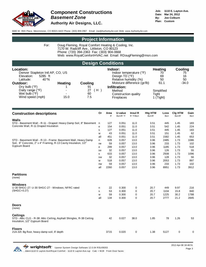
WallsSTD - Basement Wall - R-11 - Draped: Heavy Damp Soil, 8" BasementConcrete Wall, R-11 Draped Insulation
1831.454453.5111.00.051127n2241.455423.5111.00.051154e1831.454453.5111.00.051127s621.451513.5111.00.05143w
6531.4515823.5111.00.051451allSTD - Basement Wall - R-13 - Frame: Basement Wall, Heavy Damp Soil, 8" Concrete, 2" x 4" Framing, R-13 Cavity Insulation, 1/2" Gypsum Board
10861.7324853.9613.00.057628n1021.732333.9613.00.05759ne5181.7311853.9613.00.057299e551.731263.9613.00.05732se
10961.7325083.9613.00.057633s561.731283.9613.00.05732sw
8971.7320533.9613.00.057518w1021.732333.9613.00.05759nw
39121.7389513.9613.00.0572260all
Partitions(none)
WindowsU-30 SHGC-27: U-30 SHGC-27 - Windows; NFRC rated (SHGC=0.27)
20.700.30022n 2169.9744984015.8110420.700.30053s
178830.2122520.700.30059w284521.2277720.700.300134all
Doors(none)
CeilingsSTD - Attic CLG - R-38: Attic Ceiling, Asphalt Shingles, R-38 Ceiling Insulation, 1/2" Gypsum Board
531.26781.8538.00.02742
Floors21A-32t: Bg floor, heavy damp soil, 8' depth 3715 0051271.3800.020

2012-Apr-08 18:48:51Uponor System Design Software 12.0.04 RSU09203 Page 5
...ilders\1110 E Layton Ave\Royal Comfort - 1110 E Layton Ave.rup Calc = MJ8 Front Door faces:
1110 E. Layton Ave.Job:Component Constructions Mar 24, 2012Date:Main Zone Joe ColburnBy:
CustomPlan:Authority Air Designs, LLC.
6680 W. 95th Place, Westminster, CO 80021-6422 Phone: (303) 859-2967 Email: [email protected] Web: www.AuthorityAir.com
Project InformationDoug Fleming, Royal Comfort Heating & Cooling, Inc.For:7170 W. Radcliff Ave., Littleton, CO 80123Phone: (720) 394-2363 Fax: (303) 904-0668Web: www.RoyalComfortHVAC.net Email: [email protected]
Design ConditionsLocation: CoolingHeatingIndoor:
7570Indoor temperature (°F)Denver Stapleton Intl AP, CO, US1669Design TD (°F)ft5285Elevation:5050Relative humidity (%)°N40Latitude:
Outdoor: -34.061.1Moisture difference (gr/lb)CoolingHeatingInfiltration:911Dry bulb (°F)
SimplifiedMethod)H(27-Daily range (°F)TightConstruction quality60-Wet bulb (°F)1 (Tight)Fireplaces7.515.0Wind speed (mph)
Construction descriptions GainLoss Clg HTMHtg HTMInsul RU-valueAreaOrBtuhBtuh/ft²BtuhBtuh/ft²ft²-°F/BtuhBtuh/ft²-°Fft²
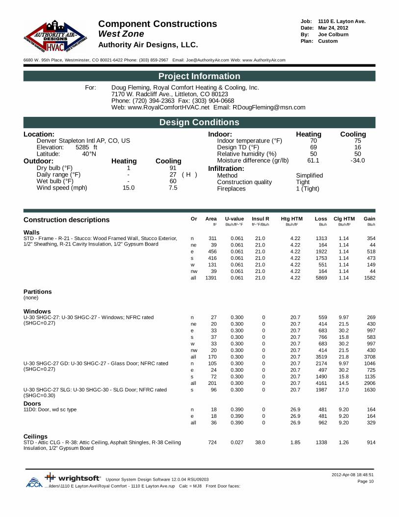
WallsSTD - Frame - R-21 - Stucco: Wood Framed Wall, Stucco Exterior, 1/2" Sheathing, R-21 Cavity Insulation, 1/2" Gypsum Board
9031.1433504.2221.00.061794n441.141644.2221.00.06139ne
6741.1424994.2221.00.061592e321.141194.2221.00.06128se
8781.1432594.2221.00.061772s331.141224.2221.00.06129sw
7971.1429564.2221.00.061701w441.141644.2221.00.06139nw
34061.14126344.2221.00.0612994all
Partitions(none)
WindowsU-30 SHGC-27: U-30 SHGC-27 - Windows; NFRC rated (SHGC=0.27)
20.700.30098n 9749.97202343021.541420.700.30020ne
115630.279220.700.30038e26026.020720.700.30010se
106415.8139720.700.30068s26026.020720.700.30010sw
275130.2188420.700.30091w43021.541420.700.30020nw
732520.7733820.700.300355allU-30 SHGC-27 GD: U-30 SHGC-27 - Glass Door; NFRC rated (SHGC=0.27)
217420.700.300105n 10469.9772530.249720.700.30024e
176515.8231820.700.300112s353714.7498920.700.300241all
U-30 SHGC-27 SLG: U-30 SHGC-30 - SLG Door; NFRC rated (SHGC=0.30)
198720.700.30096s 163017.0
Doors11D0: Door, wd sc type 1649.2048126.900.39018n
1649.2048126.900.39018e3299.2096226.900.39036all

2012-Apr-08 18:48:51Uponor System Design Software 12.0.04 RSU09203 Page 6
...ilders\1110 E Layton Ave\Royal Comfort - 1110 E Layton Ave.rup Calc = MJ8 Front Door faces:
CeilingsSTD - Attic CLG - R-38: Attic Ceiling, Asphalt Shingles, R-38 Ceiling Insulation, 1/2" Gypsum Board
21681.2631761.8538.00.0271719
Floors(none)

2012-Apr-08 18:48:51Uponor System Design Software 12.0.04 RSU09203 Page 7
...ilders\1110 E Layton Ave\Royal Comfort - 1110 E Layton Ave.rup Calc = MJ8 Front Door faces:
1110 E. Layton Ave.Job:Component Constructions Mar 24, 2012Date:Upper Zone Joe ColburnBy:
CustomPlan:Authority Air Designs, LLC.
6680 W. 95th Place, Westminster, CO 80021-6422 Phone: (303) 859-2967 Email: [email protected] Web: www.AuthorityAir.com
Project InformationDoug Fleming, Royal Comfort Heating & Cooling, Inc.For:7170 W. Radcliff Ave., Littleton, CO 80123Phone: (720) 394-2363 Fax: (303) 904-0668Web: www.RoyalComfortHVAC.net Email: [email protected]
Design ConditionsLocation: CoolingHeatingIndoor:
7570Indoor temperature (°F)Denver Stapleton Intl AP, CO, US1669Design TD (°F)ft5285Elevation:5050Relative humidity (%)°N40Latitude:
Outdoor: -34.061.1Moisture difference (gr/lb)CoolingHeatingInfiltration:911Dry bulb (°F)
SimplifiedMethod)H(27-Daily range (°F)TightConstruction quality60-Wet bulb (°F)1 (Tight)Fireplaces7.515.0Wind speed (mph)
Construction descriptions GainLoss Clg HTMHtg HTMInsul RU-valueAreaOrBtuhBtuh/ft²BtuhBtuh/ft²ft²-°F/BtuhBtuh/ft²-°Fft²
WallsSTD - Frame - R-21 - Stucco: Wood Framed Wall, Stucco Exterior, 1/2" Sheathing, R-21 Cavity Insulation, 1/2" Gypsum Board
5071.1418804.2221.00.061446n421.141564.2221.00.06137ne
5821.1421604.2221.00.061512e1231.144574.2221.00.061108se4751.1417614.2221.00.061417s271.14994.2221.00.06124sw
6391.1423704.2221.00.061562w421.141564.2221.00.06137nw
24361.1490394.2221.00.0612142all
Partitions(none)
WindowsU-30 SHGC-27: U-30 SHGC-27 - Windows; NFRC rated (SHGC=0.27)
20.700.30047n 4689.9797347321.545520.700.30022ne60530.241420.700.30020e
122115.8160420.700.30078s32526.025920.700.30013sw22730.215520.700.3008w47321.545520.700.30022nw
379318.2431620.700.300209allU-30 SHGC-27 GD: U-30 SHGC-27 - Glass Door; NFRC rated (SHGC=0.27)
83220.700.30040n 4019.97
Doors(none)
CeilingsSTD - Attic CLG - R-38: Attic Ceiling, Asphalt Shingles, R-38 Ceiling Insulation, 1/2" Gypsum Board
25861.2637891.8538.00.0272050

Floors
2012-Apr-08 18:48:51Uponor System Design Software 12.0.04 RSU09203 Page 8
...ilders\1110 E Layton Ave\Royal Comfort - 1110 E Layton Ave.rup Calc = MJ8 Front Door faces:
STD Floor - R-38: Framed Floor Over Outside Air, R-38 Cavity Insulation, Wood Floor
001171.9738.00.02959

2012-Apr-08 18:48:51Uponor System Design Software 12.0.04 RSU09203 Page 9
...ilders\1110 E Layton Ave\Royal Comfort - 1110 E Layton Ave.rup Calc = MJ8 Front Door faces:
1110 E. Layton Ave.Job:Component Constructions Mar 24, 2012Date:East Zone Joe ColburnBy:
CustomPlan:Authority Air Designs, LLC.
6680 W. 95th Place, Westminster, CO 80021-6422 Phone: (303) 859-2967 Email: [email protected] Web: www.AuthorityAir.com
Project InformationDoug Fleming, Royal Comfort Heating & Cooling, Inc.For:7170 W. Radcliff Ave., Littleton, CO 80123Phone: (720) 394-2363 Fax: (303) 904-0668Web: www.RoyalComfortHVAC.net Email: [email protected]
Design ConditionsLocation: CoolingHeatingIndoor:
7570Indoor temperature (°F)Denver Stapleton Intl AP, CO, US1669Design TD (°F)ft5285Elevation:5050Relative humidity (%)°N40Latitude:
Outdoor: -34.061.1Moisture difference (gr/lb)CoolingHeatingInfiltration:911Dry bulb (°F)
SimplifiedMethod)H(27-Daily range (°F)TightConstruction quality60-Wet bulb (°F)1 (Tight)Fireplaces7.515.0Wind speed (mph)
Construction descriptions GainLoss Clg HTMHtg HTMInsul RU-valueAreaOrBtuhBtuh/ft²BtuhBtuh/ft²ft²-°F/BtuhBtuh/ft²-°Fft²
WallsSTD - Frame - R-21 - Stucco: Wood Framed Wall, Stucco Exterior, 1/2" Sheathing, R-21 Cavity Insulation, 1/2" Gypsum Board
5491.1420374.2221.00.061483n1551.145774.2221.00.061137e321.141194.2221.00.06128se
4061.1415054.2221.00.061357s331.141224.2221.00.06129sw
6481.1424054.2221.00.061570w18241.1467654.2221.00.0611603all
Partitions(none)
WindowsU-30 SHGC-27: U-30 SHGC-27 - Windows; NFRC rated (SHGC=0.27)
20.700.30071n 7059.97146515930.210920.700.3005e26026.020720.700.30010se48115.863120.700.30031s26026.020720.700.30010sw
175330.2120120.700.30058w361719.6381920.700.300185all
U-30 SHGC-27 GD: U-30 SHGC-27 - Glass Door; NFRC rated (SHGC=0.27)
82820.700.30040s 63015.8
Doors(none)
CeilingsSTD - Attic CLG - R-38: Attic Ceiling, Asphalt Shingles, R-38 Ceiling Insulation, 1/2" Gypsum Board
12541.2618371.8538.00.027994
Floors(none)
2012-Apr-08 18:48:51Uponor System Design Software 12.0.04 RSU09203 Page 10
...ilders\1110 E Layton Ave\Royal Comfort - 1110 E Layton Ave.rup Calc = MJ8 Front Door faces:
1110 E. Layton Ave.Job:Component Constructions Mar 24, 2012Date:West Zone Joe ColburnBy:
CustomPlan:Authority Air Designs, LLC.
6680 W. 95th Place, Westminster, CO 80021-6422 Phone: (303) 859-2967 Email: [email protected] Web: www.AuthorityAir.com
Project InformationDoug Fleming, Royal Comfort Heating & Cooling, Inc.For:7170 W. Radcliff Ave., Littleton, CO 80123Phone: (720) 394-2363 Fax: (303) 904-0668Web: www.RoyalComfortHVAC.net Email: [email protected]
Design ConditionsLocation: CoolingHeatingIndoor:
7570Indoor temperature (°F)Denver Stapleton Intl AP, CO, US1669Design TD (°F)ft5285Elevation:5050Relative humidity (%)°N40Latitude:
Outdoor: -34.061.1Moisture difference (gr/lb)CoolingHeatingInfiltration:911Dry bulb (°F)
SimplifiedMethod)H(27-Daily range (°F)TightConstruction quality60-Wet bulb (°F)1 (Tight)Fireplaces7.515.0Wind speed (mph)
Construction descriptions GainLoss Clg HTMHtg HTMInsul RU-valueAreaOrBtuhBtuh/ft²BtuhBtuh/ft²ft²-°F/BtuhBtuh/ft²-°Fft²
WallsSTD - Frame - R-21 - Stucco: Wood Framed Wall, Stucco Exterior, 1/2" Sheathing, R-21 Cavity Insulation, 1/2" Gypsum Board
3541.1413134.2221.00.061311n441.141644.2221.00.06139ne
5181.1419224.2221.00.061456e4731.1417534.2221.00.061416s1491.145514.2221.00.061131w441.141644.2221.00.06139nw
15821.1458694.2221.00.0611391all
Partitions(none)
WindowsU-30 SHGC-27: U-30 SHGC-27 - Windows; NFRC rated (SHGC=0.27)
20.700.30027n 2699.9755943021.541420.700.30020ne99730.268320.700.30033e58315.876620.700.30037s99730.268320.700.30033w43021.541420.700.30020nw
370821.8351920.700.300170allU-30 SHGC-27 GD: U-30 SHGC-27 - Glass Door; NFRC rated (SHGC=0.27)
217420.700.300105n 10469.9772530.249720.700.30024e
113515.8149020.700.30072s290614.5416120.700.300201all
U-30 SHGC-27 SLG: U-30 SHGC-30 - SLG Door; NFRC rated (SHGC=0.30)
198720.700.30096s 163017.0
Doors11D0: Door, wd sc type 1649.2048126.900.39018n
1649.2048126.900.39018e3299.2096226.900.39036all
CeilingsSTD - Attic CLG - R-38: Attic Ceiling, Asphalt Shingles, R-38 Ceiling Insulation, 1/2" Gypsum Board
9141.2613381.8538.00.027724

Calculations approved by ACCA to meet all requirements of Manual J 8th Ed.2012-Apr-08 18:48:51
Uponor System Design Software 12.0.04 RSU09203 Page 1...ilders\1110 E Layton Ave\Royal Comfort - 1110 E Layton Ave.rup Calc = MJ8 Front Door faces:
1110 E. Layton Ave.Job:Right-J® WorksheetMar 24, 2012Date:Entire HouseJoe ColburnBy:CustomPlan:Authority Air Designs, LLC.
6680 W. 95th Place, Westminster, CO 80021-6422 Phone: (303) 859-2967 Email: [email protected] Web: www.AuthorityAir.com
1 Room name Entire House Basement Zone2 Exposed wall 959.5 ft 352.1 ft3 Room height 9.5 dft 8.6 dft4 Room dimensions5 Room area 9480.5 ft² 3715.1 ft²
Ty Construction U-value Or HTM Area (ft²) Load Area (ft²) Loadnumber (Btuh/ft²-°F)(Btuh/ft²-°F) (Btuh/ft²)(Btuh/ft²) or perimeter (ft) (Btuh) or perimeter (ft) (Btuh)
Heat Cool Gross N/P/S Heat Cool Gross N/P/S Heat Cool
6 WW STD - Basement Wall 0.078STD - Basement Wall 0.078 nn 3.513.51 1.451.45 127 127 445 183 127 127 445 183. WW STD - Basement Wall 0.093STD - Basement Wall 0.093 nn 3.963.96 1.731.73 649 628 2485 1086 649 628 2485 1086. GG U-30 SHGC-27U-30 SHGC-27 0.3000.300 nn 20.7020.70 9.979.97 22 0 449 216 22 0 449 216. WW STD - Frame - R-21 - 0.061STD - Frame - R-21 - 0.061 nn 4.224.22 1.141.14 1547 1239 5230 1410 0 0 0 0
11 GG U-30 SHGC-27U-30 SHGC-27 0.3000.300 nn 20.7020.70 9.979.97 145 0 2996 1442 0 0 0 0GG U-30 SHGC-27 GDU-30 SHGC-27 GD 0.3000.300 nn 20.7020.70 9.979.97 145 0 3006 1447 0 0 0 0DD 11D011D0 0.3900.390 nn 26.9126.91 9.209.20 18 18 481 164 0 0 0 0
WW STD - Basement Wall 0.093STD - Basement Wall 0.093 nene 3.963.96 1.731.73 59 59 233 102 59 59 233 102WW STD - Frame - R-21 - 0.061STD - Frame - R-21 - 0.061 nene 4.224.22 1.141.14 118 76 320 86 0 0 0 0
GG U-30 SHGC-27U-30 SHGC-27 0.3000.300 nene 20.7020.70 21.5221.52 42 0 869 904 0 0 0 0WW STD - Basement Wall 0.078STD - Basement Wall 0.078 ee 3.513.51 1.451.45 154 154 542 224 154 154 542 224WW STD - Basement Wall 0.093STD - Basement Wall 0.093 ee 3.963.96 1.731.73 299 299 1185 518 299 299 1185 518WW STD - Frame - R-21 - 0.061STD - Frame - R-21 - 0.061 ee 4.224.22 1.141.14 1204 1104 4659 1256 0 0 0 0
GG U-30 SHGC-27U-30 SHGC-27 0.3000.300 ee 20.7020.70 30.2330.23 58 0 1206 1761 0 0 0 0GG U-30 SHGC-27 GDU-30 SHGC-27 GD 0.3000.300 ee 20.7020.70 30.2330.23 24 0 497 725 0 0 0 0DD 11D011D0 0.3900.390 ee 26.9126.91 9.209.20 18 18 481 164 0 0 0 0
WW STD - Basement Wall 0.093STD - Basement Wall 0.093 sese 3.963.96 1.731.73 32 32 126 55 32 32 126 55WW STD - Frame - R-21 - 0.061STD - Frame - R-21 - 0.061 sese 4.224.22 1.141.14 146 136 575 155 0 0 0 0
GG U-30 SHGC-27U-30 SHGC-27 0.3000.300 sese 20.7020.70 25.9825.98 10 0 207 260 0 0 0 0WW STD - Basement Wall 0.078STD - Basement Wall 0.078 ss 3.513.51 1.451.45 127 127 445 183 127 127 445 183WW STD - Basement Wall 0.093STD - Basement Wall 0.093 ss 3.963.96 1.731.73 687 633 2508 1096 687 633 2508 1096
GG U-30 SHGC-27U-30 SHGC-27 0.3000.300 ss 20.7020.70 15.7615.76 53 0 1104 840 53 0 1104 840WW STD - Frame - R-21 - 0.061STD - Frame - R-21 - 0.061 ss 4.224.22 1.141.14 1543 1190 5020 1353 0 0 0 0
GG U-30 SHGC-27U-30 SHGC-27 0.3000.300 ss 20.7020.70 15.7615.76 145 0 3002 2285 0 0 0 0GG U-30 SHGC-27 GDU-30 SHGC-27 GD 0.3000.300 ss 20.7020.70 15.7615.76 112 0 2318 1765 0 0 0 0GG U-30 SHGC-27 SLGU-30 SHGC-27 SLG 0.3000.300 ss 20.7020.70 16.9816.98 96 0 1987 1630 0 0 0 0
WW STD - Basement Wall 0.093STD - Basement Wall 0.093 swsw 3.963.96 1.731.73 32 32 128 56 32 32 128 56WW STD - Frame - R-21 - 0.061STD - Frame - R-21 - 0.061 swsw 4.224.22 1.141.14 75 52 221 60 0 0 0 0
GG U-30 SHGC-27U-30 SHGC-27 0.3000.300 swsw 20.7020.70 25.9825.98 23 0 466 585 0 0 0 0WW STD - Basement Wall 0.078STD - Basement Wall 0.078 ww 3.513.51 1.451.45 43 43 151 62 43 43 151 62WW STD - Basement Wall 0.093STD - Basement Wall 0.093 ww 3.963.96 1.731.73 578 518 2053 897 578 518 2053 897
GG U-30 SHGC-27U-30 SHGC-27 0.3000.300 ww 20.7020.70 30.2330.23 59 0 1225 1788 59 0 1225 1788WW STD - Frame - R-21 - 0.061STD - Frame - R-21 - 0.061 ww 4.224.22 1.141.14 1361 1262 5326 1436 0 0 0 0
GG U-30 SHGC-27U-30 SHGC-27 0.3000.300 ww 20.7020.70 30.2330.23 99 0 2039 2977 0 0 0 0WW STD - Basement Wall 0.093STD - Basement Wall 0.093 nwnw 3.963.96 1.731.73 59 59 233 102 59 59 233 102WW STD - Frame - R-21 - 0.061STD - Frame - R-21 - 0.061 nwnw 4.224.22 1.141.14 118 76 320 86 0 0 0 0
GG U-30 SHGC-27U-30 SHGC-27 0.3000.300 nwnw 20.7020.70 21.5221.52 42 0 869 904 0 0 0 0CC STD - Attic CLG - R- 0.027STD - Attic CLG - R- 0.027 -- 1.851.85 1.261.26 3812 3812 7043 4808 42 42 78 53FF 21A-32t21A-32t 0.0200.020 -- 1.381.38 0.000.00 3715 3715 5127 0 3715 3715 5127 0FF STD Floor - R-38STD Floor - R-38 0.0290.029 -- 1.971.97 0.000.00 59 59 117 0 0 0 0 0
6 c) AED excursion 6 568
Envelope loss/gain 67693 35080 18516 8031
12 a) Infiltration 12168 1500 3865 477b) Room ventilation 0 0 0 0
13 Internal gains: Occupants @ 230230 6 1380 1 230Appliances/other 2000 0
Subtotal (lines 6 to 13) 79861 39960 22381 8738
Less external loadLess external load 0 0 0 0Less transferLess transfer 0 0 0 0RedistributionRedistribution 0 0 0 0
14 Subtotal 79861 39960 22381 873815 Duct loads 9% 13% 6876 5177 0% 0% 0 0
Total room load 86737 45137 22381 8738Air required (cfm)Air required (cfm) 3600 4003 1000 1000

Calculations approved by ACCA to meet all requirements of Manual J 8th Ed.2012-Apr-08 18:48:51
Uponor System Design Software 12.0.04 RSU09203 Page 2...ilders\1110 E Layton Ave\Royal Comfort - 1110 E Layton Ave.rup Calc = MJ8 Front Door faces:
1110 E. Layton Ave.Job:Right-J® WorksheetMar 24, 2012Date:Entire HouseJoe ColburnBy:CustomPlan:Authority Air Designs, LLC.
6680 W. 95th Place, Westminster, CO 80021-6422 Phone: (303) 859-2967 Email: [email protected] Web: www.AuthorityAir.com
1 Room name Main Zone Upper Zone2 Exposed wall 352.1 ft 255.3 ft3 Room height 10.5 dft 9.3 dft4 Room dimensions5 Room area 3715.1 ft² 2050.4 ft²
Ty Construction U-value Or HTM Area (ft²) Load Area (ft²) Loadnumber (Btuh/ft²-°F)(Btuh/ft²-°F) (Btuh/ft²)(Btuh/ft²) or perimeter (ft) (Btuh) or perimeter (ft) (Btuh)
Heat Cool Gross N/P/S Heat Cool Gross N/P/S Heat Cool
6 WW STD - Basement Wall 0.078STD - Basement Wall 0.078 nn 3.513.51 1.451.45 0 0 0 0 0 0 0 0. WW STD - Basement Wall 0.093STD - Basement Wall 0.093 nn 3.963.96 1.731.73 0 0 0 0 0 0 0 0. GG U-30 SHGC-27U-30 SHGC-27 0.3000.300 nn 20.7020.70 9.979.97 0 0 0 0 0 0 0 0. WW STD - Frame - R-21 - 0.061STD - Frame - R-21 - 0.061 nn 4.224.22 1.141.14 1014 794 3350 903 533 446 1880 507
11 GG U-30 SHGC-27U-30 SHGC-27 0.3000.300 nn 20.7020.70 9.979.97 98 0 2023 974 47 0 973 468GG U-30 SHGC-27 GDU-30 SHGC-27 GD 0.3000.300 nn 20.7020.70 9.979.97 105 0 2174 1046 40 0 832 401DD 11D011D0 0.3900.390 nn 26.9126.91 9.209.20 18 18 481 164 0 0 0 0
WW STD - Basement Wall 0.093STD - Basement Wall 0.093 nene 3.963.96 1.731.73 0 0 0 0 0 0 0 0WW STD - Frame - R-21 - 0.061STD - Frame - R-21 - 0.061 nene 4.224.22 1.141.14 59 39 164 44 59 37 156 42
GG U-30 SHGC-27U-30 SHGC-27 0.3000.300 nene 20.7020.70 21.5221.52 20 0 414 430 22 0 455 473WW STD - Basement Wall 0.078STD - Basement Wall 0.078 ee 3.513.51 1.451.45 0 0 0 0 0 0 0 0WW STD - Basement Wall 0.093STD - Basement Wall 0.093 ee 3.963.96 1.731.73 0 0 0 0 0 0 0 0WW STD - Frame - R-21 - 0.061STD - Frame - R-21 - 0.061 ee 4.224.22 1.141.14 672 592 2499 674 532 512 2160 582
GG U-30 SHGC-27U-30 SHGC-27 0.3000.300 ee 20.7020.70 30.2330.23 38 0 792 1156 20 0 414 605GG U-30 SHGC-27 GDU-30 SHGC-27 GD 0.3000.300 ee 20.7020.70 30.2330.23 24 0 497 725 0 0 0 0DD 11D011D0 0.3900.390 ee 26.9126.91 9.209.20 18 18 481 164 0 0 0 0
WW STD - Basement Wall 0.093STD - Basement Wall 0.093 sese 3.963.96 1.731.73 0 0 0 0 0 0 0 0WW STD - Frame - R-21 - 0.061STD - Frame - R-21 - 0.061 sese 4.224.22 1.141.14 38 28 119 32 108 108 457 123
GG U-30 SHGC-27U-30 SHGC-27 0.3000.300 sese 20.7020.70 25.9825.98 10 0 207 260 0 0 0 0WW STD - Basement Wall 0.078STD - Basement Wall 0.078 ss 3.513.51 1.451.45 0 0 0 0 0 0 0 0WW STD - Basement Wall 0.093STD - Basement Wall 0.093 ss 3.963.96 1.731.73 0 0 0 0 0 0 0 0
GG U-30 SHGC-27U-30 SHGC-27 0.3000.300 ss 20.7020.70 15.7615.76 0 0 0 0 0 0 0 0WW STD - Frame - R-21 - 0.061STD - Frame - R-21 - 0.061 ss 4.224.22 1.141.14 1048 772 3259 878 495 417 1761 475
GG U-30 SHGC-27U-30 SHGC-27 0.3000.300 ss 20.7020.70 15.7615.76 68 0 1397 1064 78 0 1604 1221GG U-30 SHGC-27 GDU-30 SHGC-27 GD 0.3000.300 ss 20.7020.70 15.7615.76 112 0 2318 1765 0 0 0 0GG U-30 SHGC-27 SLGU-30 SHGC-27 SLG 0.3000.300 ss 20.7020.70 16.9816.98 96 0 1987 1630 0 0 0 0
WW STD - Basement Wall 0.093STD - Basement Wall 0.093 swsw 3.963.96 1.731.73 0 0 0 0 0 0 0 0WW STD - Frame - R-21 - 0.061STD - Frame - R-21 - 0.061 swsw 4.224.22 1.141.14 39 29 122 33 36 24 99 27
GG U-30 SHGC-27U-30 SHGC-27 0.3000.300 swsw 20.7020.70 25.9825.98 10 0 207 260 13 0 259 325WW STD - Basement Wall 0.078STD - Basement Wall 0.078 ww 3.513.51 1.451.45 0 0 0 0 0 0 0 0WW STD - Basement Wall 0.093STD - Basement Wall 0.093 ww 3.963.96 1.731.73 0 0 0 0 0 0 0 0
GG U-30 SHGC-27U-30 SHGC-27 0.3000.300 ww 20.7020.70 30.2330.23 0 0 0 0 0 0 0 0WW STD - Frame - R-21 - 0.061STD - Frame - R-21 - 0.061 ww 4.224.22 1.141.14 792 701 2956 797 569 562 2370 639
GG U-30 SHGC-27U-30 SHGC-27 0.3000.300 ww 20.7020.70 30.2330.23 91 0 1884 2751 8 0 155 227WW STD - Basement Wall 0.093STD - Basement Wall 0.093 nwnw 3.963.96 1.731.73 0 0 0 0 0 0 0 0WW STD - Frame - R-21 - 0.061STD - Frame - R-21 - 0.061 nwnw 4.224.22 1.141.14 59 39 164 44 59 37 156 42
GG U-30 SHGC-27U-30 SHGC-27 0.3000.300 nwnw 20.7020.70 21.5221.52 20 0 414 430 22 0 455 473CC STD - Attic CLG - R- 0.027STD - Attic CLG - R- 0.027 -- 1.851.85 1.261.26 1719 1719 3176 2168 2050 2050 3789 2586FF 21A-32t21A-32t 0.0200.020 -- 1.381.38 0.000.00 0 0 0 0 0 0 0 0FF STD Floor - R-38STD Floor - R-38 0.0290.029 -- 1.971.97 0.000.00 0 0 0 0 59 59 117 0
6 c) AED excursion 0 0
Envelope loss/gain 31085 18395 18092 9216
12 a) Infiltration 5055 623 3248 400b) Room ventilation 0 0 0 0
13 Internal gains: Occupants @ 230230 2 460 3 690Appliances/other 2000 0
Subtotal (lines 6 to 13) 36140 21478 21340 10306
Less external loadLess external load 0 0 0 0Less transferLess transfer 0 0 0 0RedistributionRedistribution 0 0 0 0
14 Subtotal 36140 21478 21340 1030615 Duct loads 0% 0% 0 0 32% 51% 6876 5293
Total room load 36140 21478 28216 15599Air required (cfm)Air required (cfm) 1600 1600 1000 1000

Calculations approved by ACCA to meet all requirements of Manual J 8th Ed.2012-Apr-08 18:48:51
Uponor System Design Software 12.0.04 RSU09203 Page 3...ilders\1110 E Layton Ave\Royal Comfort - 1110 E Layton Ave.rup Calc = MJ8 Front Door faces:
1110 E. Layton Ave.Job:Right-J® WorksheetMar 24, 2012Date:Basement ZoneJoe ColburnBy:CustomPlan:Authority Air Designs, LLC.
6680 W. 95th Place, Westminster, CO 80021-6422 Phone: (303) 859-2967 Email: [email protected] Web: www.AuthorityAir.com
1 Room name Basement Zone Dn Crawl2 Exposed wall 352.1 ft 112.7 ft3 Room height 8.6 dft 4.0 heat/coolft4 Room dimensions ft880.5x1.05 Room area 3715.1 ft² 880.5 ft²
Ty Construction U-value Or HTM Area (ft²) Load Area (ft²) Loadnumber (Btuh/ft²-°F)(Btuh/ft²-°F) (Btuh/ft²)(Btuh/ft²) or perimeter (ft) (Btuh) or perimeter (ft) (Btuh)
Heat Cool Gross N/P/S Heat Cool Gross N/P/S Heat Cool
6 WW STD - Basement Wall 0.078STD - Basement Wall 0.078 nn 3.513.51 1.451.45 127 127 445 183 127 127 445 183. WW STD - Basement Wall 0.093STD - Basement Wall 0.093 nn 3.963.96 1.731.73 649 628 2485 1086 0 0 0 0. GG U-30 SHGC-27U-30 SHGC-27 0.3000.300 nn 20.7020.70 9.979.97 22 0 449 216 0 0 0 0. WW STD - Frame - R-21 - 0.061STD - Frame - R-21 - 0.061 nn 0.000.00 0.000.00 0 0 0 0 0 0 0 0
11 GG U-30 SHGC-27U-30 SHGC-27 0.3000.300 nn 0.000.00 0.000.00 0 0 0 0 0 0 0 0GG U-30 SHGC-27 GDU-30 SHGC-27 GD 0.3000.300 nn 0.000.00 0.000.00 0 0 0 0 0 0 0 0DD 11D011D0 0.3900.390 nn 0.000.00 0.000.00 0 0 0 0 0 0 0 0
WW STD - Basement Wall 0.093STD - Basement Wall 0.093 nene 3.963.96 1.731.73 59 59 233 102 0 0 0 0WW STD - Frame - R-21 - 0.061STD - Frame - R-21 - 0.061 nene 0.000.00 0.000.00 0 0 0 0 0 0 0 0
GG U-30 SHGC-27U-30 SHGC-27 0.3000.300 nene 0.000.00 0.000.00 0 0 0 0 0 0 0 0WW STD - Basement Wall 0.078STD - Basement Wall 0.078 ee 3.513.51 1.451.45 154 154 542 224 154 154 542 224WW STD - Basement Wall 0.093STD - Basement Wall 0.093 ee 3.963.96 1.731.73 299 299 1185 518 0 0 0 0WW STD - Frame - R-21 - 0.061STD - Frame - R-21 - 0.061 ee 0.000.00 0.000.00 0 0 0 0 0 0 0 0
GG U-30 SHGC-27U-30 SHGC-27 0.3000.300 ee 0.000.00 0.000.00 0 0 0 0 0 0 0 0GG U-30 SHGC-27 GDU-30 SHGC-27 GD 0.3000.300 ee 0.000.00 0.000.00 0 0 0 0 0 0 0 0DD 11D011D0 0.3900.390 ee 0.000.00 0.000.00 0 0 0 0 0 0 0 0
WW STD - Basement Wall 0.093STD - Basement Wall 0.093 sese 3.963.96 1.731.73 32 32 126 55 0 0 0 0WW STD - Frame - R-21 - 0.061STD - Frame - R-21 - 0.061 sese 0.000.00 0.000.00 0 0 0 0 0 0 0 0
GG U-30 SHGC-27U-30 SHGC-27 0.3000.300 sese 0.000.00 0.000.00 0 0 0 0 0 0 0 0WW STD - Basement Wall 0.078STD - Basement Wall 0.078 ss 3.513.51 1.451.45 127 127 445 183 127 127 445 183WW STD - Basement Wall 0.093STD - Basement Wall 0.093 ss 3.963.96 1.731.73 687 633 2508 1096 0 0 0 0
GG U-30 SHGC-27U-30 SHGC-27 0.3000.300 ss 20.7020.70 15.7615.76 53 0 1104 840 0 0 0 0WW STD - Frame - R-21 - 0.061STD - Frame - R-21 - 0.061 ss 0.000.00 0.000.00 0 0 0 0 0 0 0 0
GG U-30 SHGC-27U-30 SHGC-27 0.3000.300 ss 0.000.00 0.000.00 0 0 0 0 0 0 0 0GG U-30 SHGC-27 GDU-30 SHGC-27 GD 0.3000.300 ss 0.000.00 0.000.00 0 0 0 0 0 0 0 0GG U-30 SHGC-27 SLGU-30 SHGC-27 SLG 0.3000.300 ss 0.000.00 0.000.00 0 0 0 0 0 0 0 0
WW STD - Basement Wall 0.093STD - Basement Wall 0.093 swsw 3.963.96 1.731.73 32 32 128 56 0 0 0 0WW STD - Frame - R-21 - 0.061STD - Frame - R-21 - 0.061 swsw 0.000.00 0.000.00 0 0 0 0 0 0 0 0
GG U-30 SHGC-27U-30 SHGC-27 0.3000.300 swsw 0.000.00 0.000.00 0 0 0 0 0 0 0 0WW STD - Basement Wall 0.078STD - Basement Wall 0.078 ww 3.513.51 1.451.45 43 43 151 62 43 43 151 62WW STD - Basement Wall 0.093STD - Basement Wall 0.093 ww 3.963.96 1.731.73 578 518 2053 897 0 0 0 0
GG U-30 SHGC-27U-30 SHGC-27 0.3000.300 ww 20.7020.70 30.2330.23 59 0 1225 1788 0 0 0 0WW STD - Frame - R-21 - 0.061STD - Frame - R-21 - 0.061 ww 0.000.00 0.000.00 0 0 0 0 0 0 0 0
GG U-30 SHGC-27U-30 SHGC-27 0.3000.300 ww 0.000.00 0.000.00 0 0 0 0 0 0 0 0WW STD - Basement Wall 0.093STD - Basement Wall 0.093 nwnw 3.963.96 1.731.73 59 59 233 102 0 0 0 0WW STD - Frame - R-21 - 0.061STD - Frame - R-21 - 0.061 nwnw 0.000.00 0.000.00 0 0 0 0 0 0 0 0
GG U-30 SHGC-27U-30 SHGC-27 0.3000.300 nwnw 0.000.00 0.000.00 0 0 0 0 0 0 0 0CC STD - Attic CLG - R- 0.027STD - Attic CLG - R- 0.027 -- 1.851.85 1.261.26 42 42 78 53 0 0 0 0FF 21A-32t21A-32t 0.0200.020 -- 1.381.38 0.000.00 3715 3715 5127 0 881 881 1215 0FF STD Floor - R-38STD Floor - R-38 0.0290.029 -- 0.000.00 0.000.00 0 0 0 0 0 0 0 0
6 c) AED excursion 568 -47
Envelope loss/gain 18516 8031 2797 606
12 a) Infiltration 3865 477 612 75b) Room ventilation 0 0 0 0
13 Internal gains: Occupants @ 230230 1 230 0 0Appliances/other 0 0
Subtotal (lines 6 to 13) 22381 8738 3410 682
Less external loadLess external load 0 0 0 0Less transferLess transfer 0 0 0 0RedistributionRedistribution 0 0 0 0
14 Subtotal 22381 8738 3410 68215 Duct loads 0% 0% 0 0 -0% 0% 0 0
Total room load 22381 8738 3410 682Air required (cfm)Air required (cfm) 1000 1000 152 78

Calculations approved by ACCA to meet all requirements of Manual J 8th Ed.2012-Apr-08 18:48:51
Uponor System Design Software 12.0.04 RSU09203 Page 4...ilders\1110 E Layton Ave\Royal Comfort - 1110 E Layton Ave.rup Calc = MJ8 Front Door faces:
1110 E. Layton Ave.Job:Right-J® WorksheetMar 24, 2012Date:Basement ZoneJoe ColburnBy:CustomPlan:Authority Air Designs, LLC.
6680 W. 95th Place, Westminster, CO 80021-6422 Phone: (303) 859-2967 Email: [email protected] Web: www.AuthorityAir.com
1 Room name Dn Theater Dn AV2 Exposed wall 33.8 ft 14.6 ft3 Room height 10.0 heat/coolft 10.0 heat/coolft4 Room dimensions ft644.2x1.0 ft84.5x1.05 Room area 644.2 ft² 84.5 ft²
Ty Construction U-value Or HTM Area (ft²) Load Area (ft²) Loadnumber (Btuh/ft²-°F)(Btuh/ft²-°F) (Btuh/ft²)(Btuh/ft²) or perimeter (ft) (Btuh) or perimeter (ft) (Btuh)
Heat Cool Gross N/P/S Heat Cool Gross N/P/S Heat Cool
6 WW STD - Basement Wall 0.078STD - Basement Wall 0.078 nn 3.513.51 1.451.45 0 0 0 0 0 0 0 0. WW STD - Basement Wall 0.093STD - Basement Wall 0.093 nn 3.963.96 1.731.73 0 0 0 0 0 0 0 0. GG U-30 SHGC-27U-30 SHGC-27 0.3000.300 nn 20.7020.70 9.979.97 0 0 0 0 0 0 0 0. WW STD - Frame - R-21 - 0.061STD - Frame - R-21 - 0.061 nn 0.000.00 0.000.00 0 0 0 0 0 0 0 0
11 GG U-30 SHGC-27U-30 SHGC-27 0.3000.300 nn 0.000.00 0.000.00 0 0 0 0 0 0 0 0GG U-30 SHGC-27 GDU-30 SHGC-27 GD 0.3000.300 nn 0.000.00 0.000.00 0 0 0 0 0 0 0 0DD 11D011D0 0.3900.390 nn 0.000.00 0.000.00 0 0 0 0 0 0 0 0
WW STD - Basement Wall 0.093STD - Basement Wall 0.093 nene 3.963.96 1.731.73 0 0 0 0 0 0 0 0WW STD - Frame - R-21 - 0.061STD - Frame - R-21 - 0.061 nene 0.000.00 0.000.00 0 0 0 0 0 0 0 0
GG U-30 SHGC-27U-30 SHGC-27 0.3000.300 nene 0.000.00 0.000.00 0 0 0 0 0 0 0 0WW STD - Basement Wall 0.078STD - Basement Wall 0.078 ee 3.513.51 1.451.45 0 0 0 0 0 0 0 0WW STD - Basement Wall 0.093STD - Basement Wall 0.093 ee 3.963.96 1.731.73 20 20 79 35 0 0 0 0WW STD - Frame - R-21 - 0.061STD - Frame - R-21 - 0.061 ee 0.000.00 0.000.00 0 0 0 0 0 0 0 0
GG U-30 SHGC-27U-30 SHGC-27 0.3000.300 ee 0.000.00 0.000.00 0 0 0 0 0 0 0 0GG U-30 SHGC-27 GDU-30 SHGC-27 GD 0.3000.300 ee 0.000.00 0.000.00 0 0 0 0 0 0 0 0DD 11D011D0 0.3900.390 ee 0.000.00 0.000.00 0 0 0 0 0 0 0 0
WW STD - Basement Wall 0.093STD - Basement Wall 0.093 sese 3.963.96 1.731.73 0 0 0 0 0 0 0 0WW STD - Frame - R-21 - 0.061STD - Frame - R-21 - 0.061 sese 0.000.00 0.000.00 0 0 0 0 0 0 0 0
GG U-30 SHGC-27U-30 SHGC-27 0.3000.300 sese 0.000.00 0.000.00 0 0 0 0 0 0 0 0WW STD - Basement Wall 0.078STD - Basement Wall 0.078 ss 3.513.51 1.451.45 0 0 0 0 0 0 0 0WW STD - Basement Wall 0.093STD - Basement Wall 0.093 ss 3.963.96 1.731.73 298 254 1006 440 86 86 340 149
GG U-30 SHGC-27U-30 SHGC-27 0.3000.300 ss 20.7020.70 15.7615.76 43 0 897 683 0 0 0 0WW STD - Frame - R-21 - 0.061STD - Frame - R-21 - 0.061 ss 0.000.00 0.000.00 0 0 0 0 0 0 0 0
GG U-30 SHGC-27U-30 SHGC-27 0.3000.300 ss 0.000.00 0.000.00 0 0 0 0 0 0 0 0GG U-30 SHGC-27 GDU-30 SHGC-27 GD 0.3000.300 ss 0.000.00 0.000.00 0 0 0 0 0 0 0 0GG U-30 SHGC-27 SLGU-30 SHGC-27 SLG 0.3000.300 ss 0.000.00 0.000.00 0 0 0 0 0 0 0 0
WW STD - Basement Wall 0.093STD - Basement Wall 0.093 swsw 3.963.96 1.731.73 0 0 0 0 0 0 0 0WW STD - Frame - R-21 - 0.061STD - Frame - R-21 - 0.061 swsw 0.000.00 0.000.00 0 0 0 0 0 0 0 0
GG U-30 SHGC-27U-30 SHGC-27 0.3000.300 swsw 0.000.00 0.000.00 0 0 0 0 0 0 0 0WW STD - Basement Wall 0.078STD - Basement Wall 0.078 ww 3.513.51 1.451.45 0 0 0 0 0 0 0 0WW STD - Basement Wall 0.093STD - Basement Wall 0.093 ww 3.963.96 1.731.73 20 20 79 35 60 60 238 104
GG U-30 SHGC-27U-30 SHGC-27 0.3000.300 ww 20.7020.70 30.2330.23 0 0 0 0 0 0 0 0WW STD - Frame - R-21 - 0.061STD - Frame - R-21 - 0.061 ww 0.000.00 0.000.00 0 0 0 0 0 0 0 0
GG U-30 SHGC-27U-30 SHGC-27 0.3000.300 ww 0.000.00 0.000.00 0 0 0 0 0 0 0 0WW STD - Basement Wall 0.093STD - Basement Wall 0.093 nwnw 3.963.96 1.731.73 0 0 0 0 0 0 0 0WW STD - Frame - R-21 - 0.061STD - Frame - R-21 - 0.061 nwnw 0.000.00 0.000.00 0 0 0 0 0 0 0 0
GG U-30 SHGC-27U-30 SHGC-27 0.3000.300 nwnw 0.000.00 0.000.00 0 0 0 0 0 0 0 0CC STD - Attic CLG - R- 0.027STD - Attic CLG - R- 0.027 -- 1.851.85 1.261.26 0 0 0 0 0 0 0 0FF 21A-32t21A-32t 0.0200.020 -- 1.381.38 0.000.00 644 644 889 0 85 85 117 0FF STD Floor - R-38STD Floor - R-38 0.0290.029 -- 0.000.00 0.000.00 0 0 0 0 0 0 0 0
6 c) AED excursion 101 -18
Envelope loss/gain 2951 1293 694 235
12 a) Infiltration 458 57 198 24b) Room ventilation 0 0 0 0
13 Internal gains: Occupants @ 230230 0 0 0 0Appliances/other 0 0
Subtotal (lines 6 to 13) 3409 1350 892 259
Less external loadLess external load 0 0 0 0Less transferLess transfer 0 0 0 0RedistributionRedistribution 131 36 123 34
14 Subtotal 3540 1386 1015 29315 Duct loads -0% 0% 0 0 -0% 0% 0 0
Total room load 3540 1386 1015 293Air required (cfm)Air required (cfm) 158 159 45 34

Calculations approved by ACCA to meet all requirements of Manual J 8th Ed.2012-Apr-08 18:48:51
Uponor System Design Software 12.0.04 RSU09203 Page 5...ilders\1110 E Layton Ave\Royal Comfort - 1110 E Layton Ave.rup Calc = MJ8 Front Door faces:
1110 E. Layton Ave.Job:Right-J® WorksheetMar 24, 2012Date:Basement ZoneJoe ColburnBy:CustomPlan:Authority Air Designs, LLC.
6680 W. 95th Place, Westminster, CO 80021-6422 Phone: (303) 859-2967 Email: [email protected] Web: www.AuthorityAir.com
1 Room name Dn Billiards Dn Mech2 Exposed wall 43.5 ft 25.8 ft3 Room height 10.0 heat/coolft 10.0 heat/coolft4 Room dimensions ft586.7x1.0 ft191.1x1.05 Room area 586.7 ft² 191.1 ft²
Ty Construction U-value Or HTM Area (ft²) Load Area (ft²) Loadnumber (Btuh/ft²-°F)(Btuh/ft²-°F) (Btuh/ft²)(Btuh/ft²) or perimeter (ft) (Btuh) or perimeter (ft) (Btuh)
Heat Cool Gross N/P/S Heat Cool Gross N/P/S Heat Cool
6 WW STD - Basement Wall 0.078STD - Basement Wall 0.078 nn 3.513.51 1.451.45 0 0 0 0 0 0 0 0. WW STD - Basement Wall 0.093STD - Basement Wall 0.093 nn 3.963.96 1.731.73 158 137 541 237 178 178 703 307. GG U-30 SHGC-27U-30 SHGC-27 0.3000.300 nn 20.7020.70 9.979.97 22 0 449 216 0 0 0 0. WW STD - Frame - R-21 - 0.061STD - Frame - R-21 - 0.061 nn 0.000.00 0.000.00 0 0 0 0 0 0 0 0
11 GG U-30 SHGC-27U-30 SHGC-27 0.3000.300 nn 0.000.00 0.000.00 0 0 0 0 0 0 0 0GG U-30 SHGC-27 GDU-30 SHGC-27 GD 0.3000.300 nn 0.000.00 0.000.00 0 0 0 0 0 0 0 0DD 11D011D0 0.3900.390 nn 0.000.00 0.000.00 0 0 0 0 0 0 0 0
WW STD - Basement Wall 0.093STD - Basement Wall 0.093 nene 3.963.96 1.731.73 59 59 233 102 0 0 0 0WW STD - Frame - R-21 - 0.061STD - Frame - R-21 - 0.061 nene 0.000.00 0.000.00 0 0 0 0 0 0 0 0
GG U-30 SHGC-27U-30 SHGC-27 0.3000.300 nene 0.000.00 0.000.00 0 0 0 0 0 0 0 0WW STD - Basement Wall 0.078STD - Basement Wall 0.078 ee 3.513.51 1.451.45 0 0 0 0 0 0 0 0WW STD - Basement Wall 0.093STD - Basement Wall 0.093 ee 3.963.96 1.731.73 139 139 551 241 45 45 178 78WW STD - Frame - R-21 - 0.061STD - Frame - R-21 - 0.061 ee 0.000.00 0.000.00 0 0 0 0 0 0 0 0
GG U-30 SHGC-27U-30 SHGC-27 0.3000.300 ee 0.000.00 0.000.00 0 0 0 0 0 0 0 0GG U-30 SHGC-27 GDU-30 SHGC-27 GD 0.3000.300 ee 0.000.00 0.000.00 0 0 0 0 0 0 0 0DD 11D011D0 0.3900.390 ee 0.000.00 0.000.00 0 0 0 0 0 0 0 0
WW STD - Basement Wall 0.093STD - Basement Wall 0.093 sese 3.963.96 1.731.73 0 0 0 0 0 0 0 0WW STD - Frame - R-21 - 0.061STD - Frame - R-21 - 0.061 sese 0.000.00 0.000.00 0 0 0 0 0 0 0 0
GG U-30 SHGC-27U-30 SHGC-27 0.3000.300 sese 0.000.00 0.000.00 0 0 0 0 0 0 0 0WW STD - Basement Wall 0.078STD - Basement Wall 0.078 ss 3.513.51 1.451.45 0 0 0 0 0 0 0 0WW STD - Basement Wall 0.093STD - Basement Wall 0.093 ss 3.963.96 1.731.73 0 0 0 0 0 0 0 0
GG U-30 SHGC-27U-30 SHGC-27 0.3000.300 ss 20.7020.70 15.7615.76 0 0 0 0 0 0 0 0WW STD - Frame - R-21 - 0.061STD - Frame - R-21 - 0.061 ss 0.000.00 0.000.00 0 0 0 0 0 0 0 0
GG U-30 SHGC-27U-30 SHGC-27 0.3000.300 ss 0.000.00 0.000.00 0 0 0 0 0 0 0 0GG U-30 SHGC-27 GDU-30 SHGC-27 GD 0.3000.300 ss 0.000.00 0.000.00 0 0 0 0 0 0 0 0GG U-30 SHGC-27 SLGU-30 SHGC-27 SLG 0.3000.300 ss 0.000.00 0.000.00 0 0 0 0 0 0 0 0
WW STD - Basement Wall 0.093STD - Basement Wall 0.093 swsw 3.963.96 1.731.73 0 0 0 0 0 0 0 0WW STD - Frame - R-21 - 0.061STD - Frame - R-21 - 0.061 swsw 0.000.00 0.000.00 0 0 0 0 0 0 0 0
GG U-30 SHGC-27U-30 SHGC-27 0.3000.300 swsw 0.000.00 0.000.00 0 0 0 0 0 0 0 0WW STD - Basement Wall 0.078STD - Basement Wall 0.078 ww 3.513.51 1.451.45 0 0 0 0 0 0 0 0WW STD - Basement Wall 0.093STD - Basement Wall 0.093 ww 3.963.96 1.731.73 20 20 79 35 35 35 139 61
GG U-30 SHGC-27U-30 SHGC-27 0.3000.300 ww 20.7020.70 30.2330.23 0 0 0 0 0 0 0 0WW STD - Frame - R-21 - 0.061STD - Frame - R-21 - 0.061 ww 0.000.00 0.000.00 0 0 0 0 0 0 0 0
GG U-30 SHGC-27U-30 SHGC-27 0.3000.300 ww 0.000.00 0.000.00 0 0 0 0 0 0 0 0WW STD - Basement Wall 0.093STD - Basement Wall 0.093 nwnw 3.963.96 1.731.73 59 59 233 102 0 0 0 0WW STD - Frame - R-21 - 0.061STD - Frame - R-21 - 0.061 nwnw 0.000.00 0.000.00 0 0 0 0 0 0 0 0
GG U-30 SHGC-27U-30 SHGC-27 0.3000.300 nwnw 0.000.00 0.000.00 0 0 0 0 0 0 0 0CC STD - Attic CLG - R- 0.027STD - Attic CLG - R- 0.027 -- 1.851.85 1.261.26 0 0 0 0 0 0 0 0FF 21A-32t21A-32t 0.0200.020 -- 1.381.38 0.000.00 587 587 810 0 191 191 264 0FF STD Floor - R-38STD Floor - R-38 0.0290.029 -- 0.000.00 0.000.00 0 0 0 0 0 0 0 0
6 c) AED excursion -64 -31
Envelope loss/gain 2896 868 1283 414
12 a) Infiltration 591 73 350 43b) Room ventilation 0 0 0 0
13 Internal gains: Occupants @ 230230 0 0 0 0Appliances/other 0 0
Subtotal (lines 6 to 13) 3488 940 1633 457
Less external loadLess external load 0 0 0 0Less transferLess transfer 0 0 0 0RedistributionRedistribution 52 14 288 79
14 Subtotal 3540 955 1921 53715 Duct loads -0% 0% 0 0 -0% 0% 0 0
Total room load 3540 955 1921 537Air required (cfm)Air required (cfm) 158 109 86 61

Calculations approved by ACCA to meet all requirements of Manual J 8th Ed.2012-Apr-08 18:48:51
Uponor System Design Software 12.0.04 RSU09203 Page 6...ilders\1110 E Layton Ave\Royal Comfort - 1110 E Layton Ave.rup Calc = MJ8 Front Door faces:
1110 E. Layton Ave.Job:Right-J® WorksheetMar 24, 2012Date:Basement ZoneJoe ColburnBy:CustomPlan:Authority Air Designs, LLC.
6680 W. 95th Place, Westminster, CO 80021-6422 Phone: (303) 859-2967 Email: [email protected] Web: www.AuthorityAir.com
1 Room name Dn Storage Dn Exercise2 Exposed wall 40.3 ft 26.4 ft3 Room height 10.0 heat/coolft 10.0 heat/coolft4 Room dimensions ft248.4x1.0 ft308.8x1.05 Room area 248.4 ft² 308.8 ft²
Ty Construction U-value Or HTM Area (ft²) Load Area (ft²) Loadnumber (Btuh/ft²-°F)(Btuh/ft²-°F) (Btuh/ft²)(Btuh/ft²) or perimeter (ft) (Btuh) or perimeter (ft) (Btuh)
Heat Cool Gross N/P/S Heat Cool Gross N/P/S Heat Cool
6 WW STD - Basement Wall 0.078STD - Basement Wall 0.078 nn 3.513.51 1.451.45 0 0 0 0 0 0 0 0. WW STD - Basement Wall 0.093STD - Basement Wall 0.093 nn 3.963.96 1.731.73 223 223 884 387 40 40 158 69. GG U-30 SHGC-27U-30 SHGC-27 0.3000.300 nn 20.7020.70 9.979.97 0 0 0 0 0 0 0 0. WW STD - Frame - R-21 - 0.061STD - Frame - R-21 - 0.061 nn 0.000.00 0.000.00 0 0 0 0 0 0 0 0
11 GG U-30 SHGC-27U-30 SHGC-27 0.3000.300 nn 0.000.00 0.000.00 0 0 0 0 0 0 0 0GG U-30 SHGC-27 GDU-30 SHGC-27 GD 0.3000.300 nn 0.000.00 0.000.00 0 0 0 0 0 0 0 0DD 11D011D0 0.3900.390 nn 0.000.00 0.000.00 0 0 0 0 0 0 0 0
WW STD - Basement Wall 0.093STD - Basement Wall 0.093 nene 3.963.96 1.731.73 0 0 0 0 0 0 0 0WW STD - Frame - R-21 - 0.061STD - Frame - R-21 - 0.061 nene 0.000.00 0.000.00 0 0 0 0 0 0 0 0
GG U-30 SHGC-27U-30 SHGC-27 0.3000.300 nene 0.000.00 0.000.00 0 0 0 0 0 0 0 0WW STD - Basement Wall 0.078STD - Basement Wall 0.078 ee 3.513.51 1.451.45 0 0 0 0 0 0 0 0WW STD - Basement Wall 0.093STD - Basement Wall 0.093 ee 3.963.96 1.731.73 75 75 297 130 0 0 0 0WW STD - Frame - R-21 - 0.061STD - Frame - R-21 - 0.061 ee 0.000.00 0.000.00 0 0 0 0 0 0 0 0
GG U-30 SHGC-27U-30 SHGC-27 0.3000.300 ee 0.000.00 0.000.00 0 0 0 0 0 0 0 0GG U-30 SHGC-27 GDU-30 SHGC-27 GD 0.3000.300 ee 0.000.00 0.000.00 0 0 0 0 0 0 0 0DD 11D011D0 0.3900.390 ee 0.000.00 0.000.00 0 0 0 0 0 0 0 0
WW STD - Basement Wall 0.093STD - Basement Wall 0.093 sese 3.963.96 1.731.73 0 0 0 0 0 0 0 0WW STD - Frame - R-21 - 0.061STD - Frame - R-21 - 0.061 sese 0.000.00 0.000.00 0 0 0 0 0 0 0 0
GG U-30 SHGC-27U-30 SHGC-27 0.3000.300 sese 0.000.00 0.000.00 0 0 0 0 0 0 0 0WW STD - Basement Wall 0.078STD - Basement Wall 0.078 ss 3.513.51 1.451.45 0 0 0 0 0 0 0 0WW STD - Basement Wall 0.093STD - Basement Wall 0.093 ss 3.963.96 1.731.73 0 0 0 0 70 70 277 121
GG U-30 SHGC-27U-30 SHGC-27 0.3000.300 ss 20.7020.70 15.7615.76 0 0 0 0 0 0 0 0WW STD - Frame - R-21 - 0.061STD - Frame - R-21 - 0.061 ss 0.000.00 0.000.00 0 0 0 0 0 0 0 0
GG U-30 SHGC-27U-30 SHGC-27 0.3000.300 ss 0.000.00 0.000.00 0 0 0 0 0 0 0 0GG U-30 SHGC-27 GDU-30 SHGC-27 GD 0.3000.300 ss 0.000.00 0.000.00 0 0 0 0 0 0 0 0GG U-30 SHGC-27 SLGU-30 SHGC-27 SLG 0.3000.300 ss 0.000.00 0.000.00 0 0 0 0 0 0 0 0
WW STD - Basement Wall 0.093STD - Basement Wall 0.093 swsw 3.963.96 1.731.73 0 0 0 0 0 0 0 0WW STD - Frame - R-21 - 0.061STD - Frame - R-21 - 0.061 swsw 0.000.00 0.000.00 0 0 0 0 0 0 0 0
GG U-30 SHGC-27U-30 SHGC-27 0.3000.300 swsw 0.000.00 0.000.00 0 0 0 0 0 0 0 0WW STD - Basement Wall 0.078STD - Basement Wall 0.078 ww 3.513.51 1.451.45 0 0 0 0 0 0 0 0WW STD - Basement Wall 0.093STD - Basement Wall 0.093 ww 3.963.96 1.731.73 104 104 412 180 154 117 462 202
GG U-30 SHGC-27U-30 SHGC-27 0.3000.300 ww 20.7020.70 30.2330.23 0 0 0 0 38 0 776 1134WW STD - Frame - R-21 - 0.061STD - Frame - R-21 - 0.061 ww 0.000.00 0.000.00 0 0 0 0 0 0 0 0
GG U-30 SHGC-27U-30 SHGC-27 0.3000.300 ww 0.000.00 0.000.00 0 0 0 0 0 0 0 0WW STD - Basement Wall 0.093STD - Basement Wall 0.093 nwnw 3.963.96 1.731.73 0 0 0 0 0 0 0 0WW STD - Frame - R-21 - 0.061STD - Frame - R-21 - 0.061 nwnw 0.000.00 0.000.00 0 0 0 0 0 0 0 0
GG U-30 SHGC-27U-30 SHGC-27 0.3000.300 nwnw 0.000.00 0.000.00 0 0 0 0 0 0 0 0CC STD - Attic CLG - R- 0.027STD - Attic CLG - R- 0.027 -- 1.851.85 1.261.26 0 0 0 0 42 42 78 53FF 21A-32t21A-32t 0.0200.020 -- 1.381.38 0.000.00 248 248 343 0 309 309 426 0FF STD Floor - R-38STD Floor - R-38 0.0290.029 -- 0.000.00 0.000.00 0 0 0 0 0 0 0 0
6 c) AED excursion -49 446
Envelope loss/gain 1937 648 2178 2026
12 a) Infiltration 547 67 359 44b) Room ventilation 0 0 0 0
13 Internal gains: Occupants @ 230230 0 0 0 0Appliances/other 0 0
Subtotal (lines 6 to 13) 2483 715 2537 2070
Less external loadLess external load 0 0 0 0Less transferLess transfer 0 0 0 0RedistributionRedistribution 111 31 94 26
14 Subtotal 2595 746 2632 209615 Duct loads -0% 0% 0 0 -0% 0% 0 0
Total room load 2595 746 2632 2096Air required (cfm)Air required (cfm) 116 85 118 240

Calculations approved by ACCA to meet all requirements of Manual J 8th Ed.2012-Apr-08 18:48:51
Uponor System Design Software 12.0.04 RSU09203 Page 7...ilders\1110 E Layton Ave\Royal Comfort - 1110 E Layton Ave.rup Calc = MJ8 Front Door faces:
1110 E. Layton Ave.Job:Right-J® WorksheetMar 24, 2012Date:Basement ZoneJoe ColburnBy:CustomPlan:Authority Air Designs, LLC.
6680 W. 95th Place, Westminster, CO 80021-6422 Phone: (303) 859-2967 Email: [email protected] Web: www.AuthorityAir.com
1 Room name Dn Bath 5 Dn Bedroom 52 Exposed wall 0 ft 48.7 ft3 Room height 10.0 heat/coolft 10.0 heat/coolft4 Room dimensions ft73.8x1.0 ft310.2x1.05 Room area 73.8 ft² 310.2 ft²
Ty Construction U-value Or HTM Area (ft²) Load Area (ft²) Loadnumber (Btuh/ft²-°F)(Btuh/ft²-°F) (Btuh/ft²)(Btuh/ft²) or perimeter (ft) (Btuh) or perimeter (ft) (Btuh)
Heat Cool Gross N/P/S Heat Cool Gross N/P/S Heat Cool
6 WW STD - Basement Wall 0.078STD - Basement Wall 0.078 nn 3.513.51 1.451.45 0 0 0 0 0 0 0 0. WW STD - Basement Wall 0.093STD - Basement Wall 0.093 nn 3.963.96 1.731.73 0 0 0 0 50 50 198 87. GG U-30 SHGC-27U-30 SHGC-27 0.3000.300 nn 20.7020.70 9.979.97 0 0 0 0 0 0 0 0. WW STD - Frame - R-21 - 0.061STD - Frame - R-21 - 0.061 nn 0.000.00 0.000.00 0 0 0 0 0 0 0 0
11 GG U-30 SHGC-27U-30 SHGC-27 0.3000.300 nn 0.000.00 0.000.00 0 0 0 0 0 0 0 0GG U-30 SHGC-27 GDU-30 SHGC-27 GD 0.3000.300 nn 0.000.00 0.000.00 0 0 0 0 0 0 0 0DD 11D011D0 0.3900.390 nn 0.000.00 0.000.00 0 0 0 0 0 0 0 0
WW STD - Basement Wall 0.093STD - Basement Wall 0.093 nene 3.963.96 1.731.73 0 0 0 0 0 0 0 0WW STD - Frame - R-21 - 0.061STD - Frame - R-21 - 0.061 nene 0.000.00 0.000.00 0 0 0 0 0 0 0 0
GG U-30 SHGC-27U-30 SHGC-27 0.3000.300 nene 0.000.00 0.000.00 0 0 0 0 0 0 0 0WW STD - Basement Wall 0.078STD - Basement Wall 0.078 ee 3.513.51 1.451.45 0 0 0 0 0 0 0 0WW STD - Basement Wall 0.093STD - Basement Wall 0.093 ee 3.963.96 1.731.73 0 0 0 0 20 20 79 35WW STD - Frame - R-21 - 0.061STD - Frame - R-21 - 0.061 ee 0.000.00 0.000.00 0 0 0 0 0 0 0 0
GG U-30 SHGC-27U-30 SHGC-27 0.3000.300 ee 0.000.00 0.000.00 0 0 0 0 0 0 0 0GG U-30 SHGC-27 GDU-30 SHGC-27 GD 0.3000.300 ee 0.000.00 0.000.00 0 0 0 0 0 0 0 0DD 11D011D0 0.3900.390 ee 0.000.00 0.000.00 0 0 0 0 0 0 0 0
WW STD - Basement Wall 0.093STD - Basement Wall 0.093 sese 3.963.96 1.731.73 0 0 0 0 32 32 126 55WW STD - Frame - R-21 - 0.061STD - Frame - R-21 - 0.061 sese 0.000.00 0.000.00 0 0 0 0 0 0 0 0
GG U-30 SHGC-27U-30 SHGC-27 0.3000.300 sese 0.000.00 0.000.00 0 0 0 0 0 0 0 0WW STD - Basement Wall 0.078STD - Basement Wall 0.078 ss 3.513.51 1.451.45 0 0 0 0 0 0 0 0WW STD - Basement Wall 0.093STD - Basement Wall 0.093 ss 3.963.96 1.731.73 0 0 0 0 168 168 667 291
GG U-30 SHGC-27U-30 SHGC-27 0.3000.300 ss 20.7020.70 15.7615.76 0 0 0 0 0 0 0 0WW STD - Frame - R-21 - 0.061STD - Frame - R-21 - 0.061 ss 0.000.00 0.000.00 0 0 0 0 0 0 0 0
GG U-30 SHGC-27U-30 SHGC-27 0.3000.300 ss 0.000.00 0.000.00 0 0 0 0 0 0 0 0GG U-30 SHGC-27 GDU-30 SHGC-27 GD 0.3000.300 ss 0.000.00 0.000.00 0 0 0 0 0 0 0 0GG U-30 SHGC-27 SLGU-30 SHGC-27 SLG 0.3000.300 ss 0.000.00 0.000.00 0 0 0 0 0 0 0 0
WW STD - Basement Wall 0.093STD - Basement Wall 0.093 swsw 3.963.96 1.731.73 0 0 0 0 32 32 128 56WW STD - Frame - R-21 - 0.061STD - Frame - R-21 - 0.061 swsw 0.000.00 0.000.00 0 0 0 0 0 0 0 0
GG U-30 SHGC-27U-30 SHGC-27 0.3000.300 swsw 0.000.00 0.000.00 0 0 0 0 0 0 0 0WW STD - Basement Wall 0.078STD - Basement Wall 0.078 ww 3.513.51 1.451.45 0 0 0 0 0 0 0 0WW STD - Basement Wall 0.093STD - Basement Wall 0.093 ww 3.963.96 1.731.73 0 0 0 0 184 163 643 281
GG U-30 SHGC-27U-30 SHGC-27 0.3000.300 ww 20.7020.70 30.2330.23 0 0 0 0 22 0 449 655WW STD - Frame - R-21 - 0.061STD - Frame - R-21 - 0.061 ww 0.000.00 0.000.00 0 0 0 0 0 0 0 0
GG U-30 SHGC-27U-30 SHGC-27 0.3000.300 ww 0.000.00 0.000.00 0 0 0 0 0 0 0 0WW STD - Basement Wall 0.093STD - Basement Wall 0.093 nwnw 3.963.96 1.731.73 0 0 0 0 0 0 0 0WW STD - Frame - R-21 - 0.061STD - Frame - R-21 - 0.061 nwnw 0.000.00 0.000.00 0 0 0 0 0 0 0 0
GG U-30 SHGC-27U-30 SHGC-27 0.3000.300 nwnw 0.000.00 0.000.00 0 0 0 0 0 0 0 0CC STD - Attic CLG - R- 0.027STD - Attic CLG - R- 0.027 -- 1.851.85 1.261.26 0 0 0 0 0 0 0 0FF 21A-32t21A-32t 0.0200.020 -- 1.381.38 0.000.00 74 74 102 0 310 310 428 0FF STD Floor - R-38STD Floor - R-38 0.0290.029 -- 0.000.00 0.000.00 0 0 0 0 0 0 0 0
6 c) AED excursion 0 205
Envelope loss/gain 102 0 2718 1664
12 a) Infiltration 0 0 661 82b) Room ventilation 0 0 0 0
13 Internal gains: Occupants @ 230230 0 0 1 230Appliances/other 0 0
Subtotal (lines 6 to 13) 102 0 3379 1976
Less external loadLess external load 0 0 0 0Less transferLess transfer 0 0 0 0RedistributionRedistribution 26 7 220 61
14 Subtotal 128 7 3600 203715 Duct loads -0% 0% 0 0 -0% 0% 0 0
Total room load 128 7 3600 2037Air required (cfm)Air required (cfm) 6 1 161 233
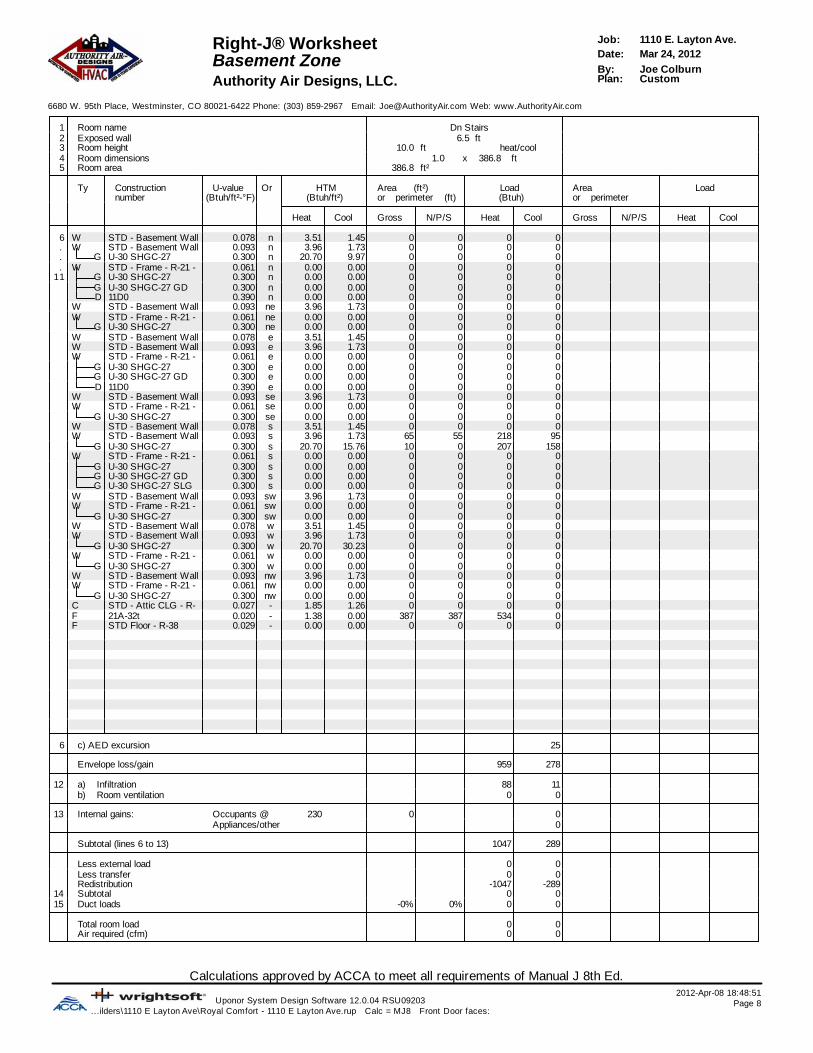
Calculations approved by ACCA to meet all requirements of Manual J 8th Ed.2012-Apr-08 18:48:51
Uponor System Design Software 12.0.04 RSU09203 Page 8...ilders\1110 E Layton Ave\Royal Comfort - 1110 E Layton Ave.rup Calc = MJ8 Front Door faces:
1110 E. Layton Ave.Job:Right-J® WorksheetMar 24, 2012Date:Basement ZoneJoe ColburnBy:CustomPlan:Authority Air Designs, LLC.
6680 W. 95th Place, Westminster, CO 80021-6422 Phone: (303) 859-2967 Email: [email protected] Web: www.AuthorityAir.com
1 Room name Dn Stairs2 Exposed wall 6.5 ft3 Room height 10.0 heat/coolft4 Room dimensions ft386.8x1.05 Room area 386.8 ft²
Ty Construction U-value Or HTM Area (ft²) Load Area Loadnumber (Btuh/ft²-°F) (Btuh/ft²) or perimeter (ft) (Btuh) or perimeter
Heat Cool Gross N/P/S Heat Cool Gross N/P/S Heat Cool
6 W STD - Basement Wall 0.078 n 3.51 1.45 0 0 0 0. W STD - Basement Wall 0.093 n 3.96 1.73 0 0 0 0. G U-30 SHGC-27 0.300 n 20.70 9.97 0 0 0 0. W STD - Frame - R-21 - 0.061 n 0.00 0.00 0 0 0 0
11 G U-30 SHGC-27 0.300 n 0.00 0.00 0 0 0 0G U-30 SHGC-27 GD 0.300 n 0.00 0.00 0 0 0 0D 11D0 0.390 n 0.00 0.00 0 0 0 0
W STD - Basement Wall 0.093 ne 3.96 1.73 0 0 0 0W STD - Frame - R-21 - 0.061 ne 0.00 0.00 0 0 0 0
G U-30 SHGC-27 0.300 ne 0.00 0.00 0 0 0 0W STD - Basement Wall 0.078 e 3.51 1.45 0 0 0 0W STD - Basement Wall 0.093 e 3.96 1.73 0 0 0 0W STD - Frame - R-21 - 0.061 e 0.00 0.00 0 0 0 0
G U-30 SHGC-27 0.300 e 0.00 0.00 0 0 0 0G U-30 SHGC-27 GD 0.300 e 0.00 0.00 0 0 0 0D 11D0 0.390 e 0.00 0.00 0 0 0 0
W STD - Basement Wall 0.093 se 3.96 1.73 0 0 0 0W STD - Frame - R-21 - 0.061 se 0.00 0.00 0 0 0 0
G U-30 SHGC-27 0.300 se 0.00 0.00 0 0 0 0W STD - Basement Wall 0.078 s 3.51 1.45 0 0 0 0W STD - Basement Wall 0.093 s 3.96 1.73 65 55 218 95
G U-30 SHGC-27 0.300 s 20.70 15.76 10 0 207 158W STD - Frame - R-21 - 0.061 s 0.00 0.00 0 0 0 0
G U-30 SHGC-27 0.300 s 0.00 0.00 0 0 0 0G U-30 SHGC-27 GD 0.300 s 0.00 0.00 0 0 0 0G U-30 SHGC-27 SLG 0.300 s 0.00 0.00 0 0 0 0
W STD - Basement Wall 0.093 sw 3.96 1.73 0 0 0 0W STD - Frame - R-21 - 0.061 sw 0.00 0.00 0 0 0 0
G U-30 SHGC-27 0.300 sw 0.00 0.00 0 0 0 0W STD - Basement Wall 0.078 w 3.51 1.45 0 0 0 0W STD - Basement Wall 0.093 w 3.96 1.73 0 0 0 0
G U-30 SHGC-27 0.300 w 20.70 30.23 0 0 0 0W STD - Frame - R-21 - 0.061 w 0.00 0.00 0 0 0 0
G U-30 SHGC-27 0.300 w 0.00 0.00 0 0 0 0W STD - Basement Wall 0.093 nw 3.96 1.73 0 0 0 0W STD - Frame - R-21 - 0.061 nw 0.00 0.00 0 0 0 0
G U-30 SHGC-27 0.300 nw 0.00 0.00 0 0 0 0C STD - Attic CLG - R- 0.027 - 1.85 1.26 0 0 0 0F 21A-32t 0.020 - 1.38 0.00 387 387 534 0F STD Floor - R-38 0.029 - 0.00 0.00 0 0 0 0
6 c) AED excursion 25
Envelope loss/gain 959 278
12 a) Infiltration 88 11b) Room ventilation 0 0
13 Internal gains: Occupants @ 230 0 0Appliances/other 0
Subtotal (lines 6 to 13) 1047 289
Less external load 0 0Less transfer 0 0Redistribution -1047 -289
14 Subtotal 0 015 Duct loads -0% 0% 0 0
Total room load 0 0Air required (cfm) 0 0

Calculations approved by ACCA to meet all requirements of Manual J 8th Ed.2012-Apr-08 18:48:51
Uponor System Design Software 12.0.04 RSU09203 Page 9...ilders\1110 E Layton Ave\Royal Comfort - 1110 E Layton Ave.rup Calc = MJ8 Front Door faces:
1110 E. Layton Ave.Job:Right-J® WorksheetMar 24, 2012Date:Main ZoneJoe ColburnBy:CustomPlan:Authority Air Designs, LLC.
6680 W. 95th Place, Westminster, CO 80021-6422 Phone: (303) 859-2967 Email: [email protected] Web: www.AuthorityAir.com
1 Room name Main Zone West Zone2 Exposed wall 352.1 ft 189.9 ft3 Room height 10.5 dft 10.0 pft4 Room dimensions5 Room area 3715.1 ft² 2053.5 ft²
Ty Construction U-value Or HTM Area (ft²) Load Area (ft²) Loadnumber (Btuh/ft²-°F)(Btuh/ft²-°F) (Btuh/ft²)(Btuh/ft²) or perimeter (ft) (Btuh) or perimeter (ft) (Btuh)
Heat Cool Gross N/P/S Heat Cool Gross N/P/S Heat Cool
6 WW STD - Basement Wall 0.078STD - Basement Wall 0.078 nn 0.000.00 0.000.00 0 0 0 0 0 0 0 0. WW STD - Basement Wall 0.093STD - Basement Wall 0.093 nn 0.000.00 0.000.00 0 0 0 0 0 0 0 0. GG U-30 SHGC-27U-30 SHGC-27 0.3000.300 nn 0.000.00 0.000.00 0 0 0 0 0 0 0 0. WW STD - Frame - R-21 - 0.061STD - Frame - R-21 - 0.061 nn 4.224.22 1.141.14 1014 794 3350 903 461 311 1313 354
11 GG U-30 SHGC-27U-30 SHGC-27 0.3000.300 nn 20.7020.70 9.979.97 98 0 2023 974 27 0 559 269GG U-30 SHGC-27 GDU-30 SHGC-27 GD 0.3000.300 nn 20.7020.70 9.979.97 105 0 2174 1046 105 0 2174 1046DD 11D011D0 0.3900.390 nn 26.9126.91 9.209.20 18 18 481 164 18 18 481 164
WW STD - Basement Wall 0.093STD - Basement Wall 0.093 nene 0.000.00 0.000.00 0 0 0 0 0 0 0 0WW STD - Frame - R-21 - 0.061STD - Frame - R-21 - 0.061 nene 4.224.22 1.141.14 59 39 164 44 59 39 164 44
GG U-30 SHGC-27U-30 SHGC-27 0.3000.300 nene 20.7020.70 21.5221.52 20 0 414 430 20 0 414 430WW STD - Basement Wall 0.078STD - Basement Wall 0.078 ee 0.000.00 0.000.00 0 0 0 0 0 0 0 0WW STD - Basement Wall 0.093STD - Basement Wall 0.093 ee 0.000.00 0.000.00 0 0 0 0 0 0 0 0WW STD - Frame - R-21 - 0.061STD - Frame - R-21 - 0.061 ee 4.224.22 1.141.14 672 592 2499 674 530 456 1922 518
GG U-30 SHGC-27U-30 SHGC-27 0.3000.300 ee 20.7020.70 30.2330.23 38 0 792 1156 33 0 683 997GG U-30 SHGC-27 GDU-30 SHGC-27 GD 0.3000.300 ee 20.7020.70 30.2330.23 24 0 497 725 24 0 497 725DD 11D011D0 0.3900.390 ee 26.9126.91 9.209.20 18 18 481 164 18 18 481 164
WW STD - Basement Wall 0.093STD - Basement Wall 0.093 sese 0.000.00 0.000.00 0 0 0 0 0 0 0 0WW STD - Frame - R-21 - 0.061STD - Frame - R-21 - 0.061 sese 4.224.22 1.141.14 38 28 119 32 0 0 0 0
GG U-30 SHGC-27U-30 SHGC-27 0.3000.300 sese 20.7020.70 25.9825.98 10 0 207 260 0 0 0 0WW STD - Basement Wall 0.078STD - Basement Wall 0.078 ss 0.000.00 0.000.00 0 0 0 0 0 0 0 0WW STD - Basement Wall 0.093STD - Basement Wall 0.093 ss 0.000.00 0.000.00 0 0 0 0 0 0 0 0
GG U-30 SHGC-27U-30 SHGC-27 0.3000.300 ss 0.000.00 0.000.00 0 0 0 0 0 0 0 0WW STD - Frame - R-21 - 0.061STD - Frame - R-21 - 0.061 ss 4.224.22 1.141.14 1048 772 3259 878 621 415 1753 473
GG U-30 SHGC-27U-30 SHGC-27 0.3000.300 ss 20.7020.70 15.7615.76 68 0 1397 1064 37 0 766 583GG U-30 SHGC-27 GDU-30 SHGC-27 GD 0.3000.300 ss 20.7020.70 15.7615.76 112 0 2318 1765 72 0 1490 1135GG U-30 SHGC-27 SLGU-30 SHGC-27 SLG 0.3000.300 ss 20.7020.70 16.9816.98 96 0 1987 1630 96 0 1987 1630
WW STD - Basement Wall 0.093STD - Basement Wall 0.093 swsw 0.000.00 0.000.00 0 0 0 0 0 0 0 0WW STD - Frame - R-21 - 0.061STD - Frame - R-21 - 0.061 swsw 4.224.22 1.141.14 39 29 122 33 0 0 0 0
GG U-30 SHGC-27U-30 SHGC-27 0.3000.300 swsw 20.7020.70 25.9825.98 10 0 207 260 0 0 0 0WW STD - Basement Wall 0.078STD - Basement Wall 0.078 ww 0.000.00 0.000.00 0 0 0 0 0 0 0 0WW STD - Basement Wall 0.093STD - Basement Wall 0.093 ww 0.000.00 0.000.00 0 0 0 0 0 0 0 0
GG U-30 SHGC-27U-30 SHGC-27 0.3000.300 ww 0.000.00 0.000.00 0 0 0 0 0 0 0 0WW STD - Frame - R-21 - 0.061STD - Frame - R-21 - 0.061 ww 4.224.22 1.141.14 792 701 2956 797 164 131 551 149
GG U-30 SHGC-27U-30 SHGC-27 0.3000.300 ww 20.7020.70 30.2330.23 91 0 1884 2751 33 0 683 997WW STD - Basement Wall 0.093STD - Basement Wall 0.093 nwnw 0.000.00 0.000.00 0 0 0 0 0 0 0 0WW STD - Frame - R-21 - 0.061STD - Frame - R-21 - 0.061 nwnw 4.224.22 1.141.14 59 39 164 44 59 39 164 44
GG U-30 SHGC-27U-30 SHGC-27 0.3000.300 nwnw 20.7020.70 21.5221.52 20 0 414 430 20 0 414 430CC STD - Attic CLG - R- 0.027STD - Attic CLG - R- 0.027 -- 1.851.85 1.261.26 1719 1719 3176 2168 724 724 1338 914FF 21A-32t21A-32t 0.0200.020 -- 0.000.00 0.000.00 0 0 0 0 0 0 0 0FF STD Floor - R-38STD Floor - R-38 0.0290.029 -- 0.000.00 0.000.00 0 0 0 0 0 0 0 0
6 c) AED excursion 0 3905
Envelope loss/gain 31085 18395 17836 14974
12 a) Infiltration 5055 623 2572 317b) Room ventilation 0 0 0 0
13 Internal gains: Occupants @ 230230 2 460 0 0Appliances/other 2000 2000
Subtotal (lines 6 to 13) 36140 21478 20408 17291
Less external loadLess external load 0 0 0 0Less transferLess transfer 0 0 0 0RedistributionRedistribution 0 0 0 0
14 Subtotal 36140 21478 20408 1729115 Duct loads 0% 0% 0 0 0% 0% 0 0
Total room load 36140 21478 20408 17291Air required (cfm)Air required (cfm) 1600 1600 904 1268

Calculations approved by ACCA to meet all requirements of Manual J 8th Ed.2012-Apr-08 18:48:51
Uponor System Design Software 12.0.04 RSU09203 Page 10...ilders\1110 E Layton Ave\Royal Comfort - 1110 E Layton Ave.rup Calc = MJ8 Front Door faces:
1110 E. Layton Ave.Job:Right-J® WorksheetMar 24, 2012Date:Main ZoneJoe ColburnBy:CustomPlan:Authority Air Designs, LLC.
6680 W. 95th Place, Westminster, CO 80021-6422 Phone: (303) 859-2967 Email: [email protected] Web: www.AuthorityAir.com
1 Room name East Zone2 Exposed wall 162.2 ft3 Room height 11.1 pft4 Room dimensions5 Room area 1661.6 ft²
Ty Construction U-value Or HTM Area (ft²) Load Area Loadnumber (Btuh/ft²-°F) (Btuh/ft²) or perimeter (ft) (Btuh) or perimeter
Heat Cool Gross N/P/S Heat Cool Gross N/P/S Heat Cool
6 W STD - Basement Wall 0.078 n 0.00 0.00 0 0 0 0. W STD - Basement Wall 0.093 n 0.00 0.00 0 0 0 0. G U-30 SHGC-27 0.300 n 0.00 0.00 0 0 0 0. W STD - Frame - R-21 - 0.061 n 4.22 1.14 553 483 2037 549
11 G U-30 SHGC-27 0.300 n 20.70 9.97 71 0 1465 705G U-30 SHGC-27 GD 0.300 n 20.70 9.97 0 0 0 0D 11D0 0.390 n 26.91 9.20 0 0 0 0
W STD - Basement Wall 0.093 ne 0.00 0.00 0 0 0 0W STD - Frame - R-21 - 0.061 ne 4.22 1.14 0 0 0 0
G U-30 SHGC-27 0.300 ne 20.70 21.52 0 0 0 0W STD - Basement Wall 0.078 e 0.00 0.00 0 0 0 0W STD - Basement Wall 0.093 e 0.00 0.00 0 0 0 0W STD - Frame - R-21 - 0.061 e 4.22 1.14 142 137 577 155
G U-30 SHGC-27 0.300 e 20.70 30.23 5 0 109 159G U-30 SHGC-27 GD 0.300 e 20.70 30.23 0 0 0 0D 11D0 0.390 e 26.91 9.20 0 0 0 0
W STD - Basement Wall 0.093 se 0.00 0.00 0 0 0 0W STD - Frame - R-21 - 0.061 se 4.22 1.14 38 28 119 32
G U-30 SHGC-27 0.300 se 20.70 25.98 10 0 207 260W STD - Basement Wall 0.078 s 0.00 0.00 0 0 0 0W STD - Basement Wall 0.093 s 0.00 0.00 0 0 0 0
G U-30 SHGC-27 0.300 s 0.00 0.00 0 0 0 0W STD - Frame - R-21 - 0.061 s 4.22 1.14 427 357 1505 406
G U-30 SHGC-27 0.300 s 20.70 15.76 31 0 631 481G U-30 SHGC-27 GD 0.300 s 20.70 15.76 40 0 828 630G U-30 SHGC-27 SLG 0.300 s 20.70 16.98 0 0 0 0
W STD - Basement Wall 0.093 sw 0.00 0.00 0 0 0 0W STD - Frame - R-21 - 0.061 sw 4.22 1.14 39 29 122 33
G U-30 SHGC-27 0.300 sw 20.70 25.98 10 0 207 260W STD - Basement Wall 0.078 w 0.00 0.00 0 0 0 0W STD - Basement Wall 0.093 w 0.00 0.00 0 0 0 0
G U-30 SHGC-27 0.300 w 0.00 0.00 0 0 0 0W STD - Frame - R-21 - 0.061 w 4.22 1.14 628 570 2405 648
G U-30 SHGC-27 0.300 w 20.70 30.23 58 0 1201 1753W STD - Basement Wall 0.093 nw 0.00 0.00 0 0 0 0W STD - Frame - R-21 - 0.061 nw 4.22 1.14 0 0 0 0
G U-30 SHGC-27 0.300 nw 20.70 21.52 0 0 0 0C STD - Attic CLG - R- 0.027 - 1.85 1.26 994 994 1837 1254F 21A-32t 0.020 - 0.00 0.00 0 0 0 0F STD Floor - R-38 0.029 - 0.00 0.00 0 0 0 0
6 c) AED excursion 1919
Envelope loss/gain 13249 9245
12 a) Infiltration 2483 306b) Room ventilation 0 0
13 Internal gains: Occupants @ 230 2 460Appliances/other 0
Subtotal (lines 6 to 13) 15732 10011
Less external load 0 0Less transfer 0 0Redistribution 0 0
14 Subtotal 15732 1001115 Duct loads 0% 0% 0 0
Total room load 15732 10011Air required (cfm) 696 734

Calculations approved by ACCA to meet all requirements of Manual J 8th Ed.2012-Apr-08 18:48:51
Uponor System Design Software 12.0.04 RSU09203 Page 11...ilders\1110 E Layton Ave\Royal Comfort - 1110 E Layton Ave.rup Calc = MJ8 Front Door faces:
1110 E. Layton Ave.Job:Right-J® WorksheetMar 24, 2012Date:Upper ZoneJoe ColburnBy:CustomPlan:Authority Air Designs, LLC.
6680 W. 95th Place, Westminster, CO 80021-6422 Phone: (303) 859-2967 Email: [email protected] Web: www.AuthorityAir.com
1 Room name Upper Zone A Bedroom2 Exposed wall 255.3 ft 32.8 ft3 Room height 9.3 dft 10.0 heat/coolft4 Room dimensions ft185.7x1.05 Room area 2050.4 ft² 185.7 ft²
Ty Construction U-value Or HTM Area (ft²) Load Area (ft²) Loadnumber (Btuh/ft²-°F)(Btuh/ft²-°F) (Btuh/ft²)(Btuh/ft²) or perimeter (ft) (Btuh) or perimeter (ft) (Btuh)
Heat Cool Gross N/P/S Heat Cool Gross N/P/S Heat Cool
6 WW STD - Basement Wall 0.078STD - Basement Wall 0.078 nn 0.000.00 0.000.00 0 0 0 0 0 0 0 0. WW STD - Basement Wall 0.093STD - Basement Wall 0.093 nn 0.000.00 0.000.00 0 0 0 0 0 0 0 0. GG U-30 SHGC-27U-30 SHGC-27 0.3000.300 nn 0.000.00 0.000.00 0 0 0 0 0 0 0 0. WW STD - Frame - R-21 - 0.061STD - Frame - R-21 - 0.061 nn 4.224.22 1.141.14 533 446 1880 507 51 51 215 58
11 GG U-30 SHGC-27U-30 SHGC-27 0.3000.300 nn 20.7020.70 9.979.97 47 0 973 468 0 0 0 0GG U-30 SHGC-27 GDU-30 SHGC-27 GD 0.3000.300 nn 20.7020.70 9.979.97 40 0 832 401 0 0 0 0DD 11D011D0 0.3900.390 nn 0.000.00 0.000.00 0 0 0 0 0 0 0 0
WW STD - Basement Wall 0.093STD - Basement Wall 0.093 nene 0.000.00 0.000.00 0 0 0 0 0 0 0 0WW STD - Frame - R-21 - 0.061STD - Frame - R-21 - 0.061 nene 4.224.22 1.141.14 59 37 156 42 0 0 0 0
GG U-30 SHGC-27U-30 SHGC-27 0.3000.300 nene 20.7020.70 21.5221.52 22 0 455 473 0 0 0 0WW STD - Basement Wall 0.078STD - Basement Wall 0.078 ee 0.000.00 0.000.00 0 0 0 0 0 0 0 0WW STD - Basement Wall 0.093STD - Basement Wall 0.093 ee 0.000.00 0.000.00 0 0 0 0 0 0 0 0WW STD - Frame - R-21 - 0.061STD - Frame - R-21 - 0.061 ee 4.224.22 1.141.14 532 512 2160 582 129 109 461 124
GG U-30 SHGC-27U-30 SHGC-27 0.3000.300 ee 20.7020.70 30.2330.23 20 0 414 605 20 0 414 605GG U-30 SHGC-27 GDU-30 SHGC-27 GD 0.3000.300 ee 0.000.00 0.000.00 0 0 0 0 0 0 0 0DD 11D011D0 0.3900.390 ee 0.000.00 0.000.00 0 0 0 0 0 0 0 0
WW STD - Basement Wall 0.093STD - Basement Wall 0.093 sese 0.000.00 0.000.00 0 0 0 0 0 0 0 0WW STD - Frame - R-21 - 0.061STD - Frame - R-21 - 0.061 sese 4.224.22 1.141.14 108 108 457 123 0 0 0 0
GG U-30 SHGC-27U-30 SHGC-27 0.3000.300 sese 0.000.00 0.000.00 0 0 0 0 0 0 0 0WW STD - Basement Wall 0.078STD - Basement Wall 0.078 ss 0.000.00 0.000.00 0 0 0 0 0 0 0 0WW STD - Basement Wall 0.093STD - Basement Wall 0.093 ss 0.000.00 0.000.00 0 0 0 0 0 0 0 0
GG U-30 SHGC-27U-30 SHGC-27 0.3000.300 ss 0.000.00 0.000.00 0 0 0 0 0 0 0 0WW STD - Frame - R-21 - 0.061STD - Frame - R-21 - 0.061 ss 4.224.22 1.141.14 495 417 1761 475 148 148 622 168
GG U-30 SHGC-27U-30 SHGC-27 0.3000.300 ss 20.7020.70 15.7615.76 78 0 1604 1221 0 0 0 0GG U-30 SHGC-27 GDU-30 SHGC-27 GD 0.3000.300 ss 0.000.00 0.000.00 0 0 0 0 0 0 0 0GG U-30 SHGC-27 SLGU-30 SHGC-27 SLG 0.3000.300 ss 0.000.00 0.000.00 0 0 0 0 0 0 0 0
WW STD - Basement Wall 0.093STD - Basement Wall 0.093 swsw 0.000.00 0.000.00 0 0 0 0 0 0 0 0WW STD - Frame - R-21 - 0.061STD - Frame - R-21 - 0.061 swsw 4.224.22 1.141.14 36 24 99 27 0 0 0 0
GG U-30 SHGC-27U-30 SHGC-27 0.3000.300 swsw 20.7020.70 25.9825.98 13 0 259 325 0 0 0 0WW STD - Basement Wall 0.078STD - Basement Wall 0.078 ww 0.000.00 0.000.00 0 0 0 0 0 0 0 0WW STD - Basement Wall 0.093STD - Basement Wall 0.093 ww 0.000.00 0.000.00 0 0 0 0 0 0 0 0
GG U-30 SHGC-27U-30 SHGC-27 0.3000.300 ww 0.000.00 0.000.00 0 0 0 0 0 0 0 0WW STD - Frame - R-21 - 0.061STD - Frame - R-21 - 0.061 ww 4.224.22 1.141.14 569 562 2370 639 0 0 0 0
GG U-30 SHGC-27U-30 SHGC-27 0.3000.300 ww 20.7020.70 30.2330.23 8 0 155 227 0 0 0 0WW STD - Basement Wall 0.093STD - Basement Wall 0.093 nwnw 0.000.00 0.000.00 0 0 0 0 0 0 0 0WW STD - Frame - R-21 - 0.061STD - Frame - R-21 - 0.061 nwnw 4.224.22 1.141.14 59 37 156 42 0 0 0 0
GG U-30 SHGC-27U-30 SHGC-27 0.3000.300 nwnw 20.7020.70 21.5221.52 22 0 455 473 0 0 0 0CC STD - Attic CLG - R- 0.027STD - Attic CLG - R- 0.027 -- 1.851.85 1.261.26 2050 2050 3789 2586 186 186 343 234FF 21A-32t21A-32t 0.0200.020 -- 0.000.00 0.000.00 0 0 0 0 0 0 0 0FF STD Floor - R-38STD Floor - R-38 0.0290.029 -- 1.971.97 0.000.00 59 59 117 0 0 0 0 0
6 c) AED excursion 0 9
Envelope loss/gain 18092 9216 2055 1198
12 a) Infiltration 3248 400 445 55b) Room ventilation 0 0 0 0
13 Internal gains: Occupants @ 230230 3 690 1 230Appliances/other 0 0
Subtotal (lines 6 to 13) 21340 10306 2500 1482
Less external loadLess external load 0 0 0 0Less transferLess transfer 0 0 0 0RedistributionRedistribution 0 0 0 0
14 Subtotal 21340 10306 2500 148215 Duct loads 32% 51% 6876 5293 32% 51% 805 761
Total room load 28216 15599 3305 2244Air required (cfm)Air required (cfm) 1000 1000 117 144

Calculations approved by ACCA to meet all requirements of Manual J 8th Ed.2012-Apr-08 18:48:51
Uponor System Design Software 12.0.04 RSU09203 Page 12...ilders\1110 E Layton Ave\Royal Comfort - 1110 E Layton Ave.rup Calc = MJ8 Front Door faces:
1110 E. Layton Ave.Job:Right-J® WorksheetMar 24, 2012Date:Upper ZoneJoe ColburnBy:CustomPlan:Authority Air Designs, LLC.
6680 W. 95th Place, Westminster, CO 80021-6422 Phone: (303) 859-2967 Email: [email protected] Web: www.AuthorityAir.com
1 Room name A Bath A WIC2 Exposed wall 25.2 ft 12.2 ft3 Room height 9.0 heat/coolft 9.0 heat/coolft4 Room dimensions ft85.4x1.0 ft6.9x8.95 Room area 85.4 ft² 61.7 ft²
Ty Construction U-value Or HTM Area (ft²) Load Area (ft²) Loadnumber (Btuh/ft²-°F)(Btuh/ft²-°F) (Btuh/ft²)(Btuh/ft²) or perimeter (ft) (Btuh) or perimeter (ft) (Btuh)
Heat Cool Gross N/P/S Heat Cool Gross N/P/S Heat Cool
6 WW STD - Basement Wall 0.078STD - Basement Wall 0.078 nn 0.000.00 0.000.00 0 0 0 0 0 0 0 0. WW STD - Basement Wall 0.093STD - Basement Wall 0.093 nn 0.000.00 0.000.00 0 0 0 0 0 0 0 0. GG U-30 SHGC-27U-30 SHGC-27 0.3000.300 nn 0.000.00 0.000.00 0 0 0 0 0 0 0 0. WW STD - Frame - R-21 - 0.061STD - Frame - R-21 - 0.061 nn 4.224.22 1.141.14 87 82 346 93 0 0 0 0
11 GG U-30 SHGC-27U-30 SHGC-27 0.3000.300 nn 20.7020.70 9.979.97 5 0 104 50 0 0 0 0GG U-30 SHGC-27 GDU-30 SHGC-27 GD 0.3000.300 nn 20.7020.70 9.979.97 0 0 0 0 0 0 0 0DD 11D011D0 0.3900.390 nn 0.000.00 0.000.00 0 0 0 0 0 0 0 0
WW STD - Basement Wall 0.093STD - Basement Wall 0.093 nene 0.000.00 0.000.00 0 0 0 0 0 0 0 0WW STD - Frame - R-21 - 0.061STD - Frame - R-21 - 0.061 nene 4.224.22 1.141.14 0 0 0 0 0 0 0 0
GG U-30 SHGC-27U-30 SHGC-27 0.3000.300 nene 20.7020.70 21.5221.52 0 0 0 0 0 0 0 0WW STD - Basement Wall 0.078STD - Basement Wall 0.078 ee 0.000.00 0.000.00 0 0 0 0 0 0 0 0WW STD - Basement Wall 0.093STD - Basement Wall 0.093 ee 0.000.00 0.000.00 0 0 0 0 0 0 0 0WW STD - Frame - R-21 - 0.061STD - Frame - R-21 - 0.061 ee 4.224.22 1.141.14 98 98 411 111 29 29 123 33
GG U-30 SHGC-27U-30 SHGC-27 0.3000.300 ee 20.7020.70 30.2330.23 0 0 0 0 0 0 0 0GG U-30 SHGC-27 GDU-30 SHGC-27 GD 0.3000.300 ee 0.000.00 0.000.00 0 0 0 0 0 0 0 0DD 11D011D0 0.3900.390 ee 0.000.00 0.000.00 0 0 0 0 0 0 0 0
WW STD - Basement Wall 0.093STD - Basement Wall 0.093 sese 0.000.00 0.000.00 0 0 0 0 0 0 0 0WW STD - Frame - R-21 - 0.061STD - Frame - R-21 - 0.061 sese 4.224.22 1.141.14 0 0 0 0 0 0 0 0
GG U-30 SHGC-27U-30 SHGC-27 0.3000.300 sese 0.000.00 0.000.00 0 0 0 0 0 0 0 0WW STD - Basement Wall 0.078STD - Basement Wall 0.078 ss 0.000.00 0.000.00 0 0 0 0 0 0 0 0WW STD - Basement Wall 0.093STD - Basement Wall 0.093 ss 0.000.00 0.000.00 0 0 0 0 0 0 0 0
GG U-30 SHGC-27U-30 SHGC-27 0.3000.300 ss 0.000.00 0.000.00 0 0 0 0 0 0 0 0WW STD - Frame - R-21 - 0.061STD - Frame - R-21 - 0.061 ss 4.224.22 1.141.14 0 0 0 0 80 80 339 91
GG U-30 SHGC-27U-30 SHGC-27 0.3000.300 ss 20.7020.70 15.7615.76 0 0 0 0 0 0 0 0GG U-30 SHGC-27 GDU-30 SHGC-27 GD 0.3000.300 ss 0.000.00 0.000.00 0 0 0 0 0 0 0 0GG U-30 SHGC-27 SLGU-30 SHGC-27 SLG 0.3000.300 ss 0.000.00 0.000.00 0 0 0 0 0 0 0 0
WW STD - Basement Wall 0.093STD - Basement Wall 0.093 swsw 0.000.00 0.000.00 0 0 0 0 0 0 0 0WW STD - Frame - R-21 - 0.061STD - Frame - R-21 - 0.061 swsw 4.224.22 1.141.14 0 0 0 0 0 0 0 0
GG U-30 SHGC-27U-30 SHGC-27 0.3000.300 swsw 20.7020.70 25.9825.98 0 0 0 0 0 0 0 0WW STD - Basement Wall 0.078STD - Basement Wall 0.078 ww 0.000.00 0.000.00 0 0 0 0 0 0 0 0WW STD - Basement Wall 0.093STD - Basement Wall 0.093 ww 0.000.00 0.000.00 0 0 0 0 0 0 0 0
GG U-30 SHGC-27U-30 SHGC-27 0.3000.300 ww 0.000.00 0.000.00 0 0 0 0 0 0 0 0WW STD - Frame - R-21 - 0.061STD - Frame - R-21 - 0.061 ww 4.224.22 1.141.14 42 42 177 48 0 0 0 0
GG U-30 SHGC-27U-30 SHGC-27 0.3000.300 ww 20.7020.70 30.2330.23 0 0 0 0 0 0 0 0WW STD - Basement Wall 0.093STD - Basement Wall 0.093 nwnw 0.000.00 0.000.00 0 0 0 0 0 0 0 0WW STD - Frame - R-21 - 0.061STD - Frame - R-21 - 0.061 nwnw 4.224.22 1.141.14 0 0 0 0 0 0 0 0
GG U-30 SHGC-27U-30 SHGC-27 0.3000.300 nwnw 20.7020.70 21.5221.52 0 0 0 0 0 0 0 0CC STD - Attic CLG - R- 0.027STD - Attic CLG - R- 0.027 -- 1.851.85 1.261.26 85 85 158 108 62 62 114 78FF 21A-32t21A-32t 0.0200.020 -- 0.000.00 0.000.00 0 0 0 0 0 0 0 0FF STD Floor - R-38STD Floor - R-38 0.0290.029 -- 1.971.97 0.000.00 44 44 87 0 0 0 0 0
6 c) AED excursion -22 -11
Envelope loss/gain 1283 388 576 192
12 a) Infiltration 308 38 149 18b) Room ventilation 0 0 0 0
13 Internal gains: Occupants @ 230230 0 0 0 0Appliances/other 0 0
Subtotal (lines 6 to 13) 1591 426 725 210
Less external loadLess external load 0 0 0 0Less transferLess transfer 0 0 0 0RedistributionRedistribution 0 0 0 0
14 Subtotal 1591 426 725 21015 Duct loads 32% 51% 513 219 32% 51% 234 108
Total room load 2104 644 958 318Air required (cfm)Air required (cfm) 75 41 34 20

Calculations approved by ACCA to meet all requirements of Manual J 8th Ed.2012-Apr-08 18:48:51
Uponor System Design Software 12.0.04 RSU09203 Page 13...ilders\1110 E Layton Ave\Royal Comfort - 1110 E Layton Ave.rup Calc = MJ8 Front Door faces:
1110 E. Layton Ave.Job:Right-J® WorksheetMar 24, 2012Date:Upper ZoneJoe ColburnBy:CustomPlan:Authority Air Designs, LLC.
6680 W. 95th Place, Westminster, CO 80021-6422 Phone: (303) 859-2967 Email: [email protected] Web: www.AuthorityAir.com
1 Room name K Bath K Bedroom2 Exposed wall 0 ft 30.4 ft3 Room height 9.0 heat/coolft 10.0 heat/coolft4 Room dimensions ft100.9x1.0 ft225.4x1.05 Room area 100.9 ft² 225.4 ft²
Ty Construction U-value Or HTM Area (ft²) Load Area (ft²) Loadnumber (Btuh/ft²-°F)(Btuh/ft²-°F) (Btuh/ft²)(Btuh/ft²) or perimeter (ft) (Btuh) or perimeter (ft) (Btuh)
Heat Cool Gross N/P/S Heat Cool Gross N/P/S Heat Cool
6 WW STD - Basement Wall 0.078STD - Basement Wall 0.078 nn 0.000.00 0.000.00 0 0 0 0 0 0 0 0. WW STD - Basement Wall 0.093STD - Basement Wall 0.093 nn 0.000.00 0.000.00 0 0 0 0 0 0 0 0. GG U-30 SHGC-27U-30 SHGC-27 0.3000.300 nn 0.000.00 0.000.00 0 0 0 0 0 0 0 0. WW STD - Frame - R-21 - 0.061STD - Frame - R-21 - 0.061 nn 4.224.22 1.141.14 0 0 0 0 62 40 167 45
11 GG U-30 SHGC-27U-30 SHGC-27 0.3000.300 nn 20.7020.70 9.979.97 0 0 0 0 22 0 455 219GG U-30 SHGC-27 GDU-30 SHGC-27 GD 0.3000.300 nn 20.7020.70 9.979.97 0 0 0 0 0 0 0 0DD 11D011D0 0.3900.390 nn 0.000.00 0.000.00 0 0 0 0 0 0 0 0
WW STD - Basement Wall 0.093STD - Basement Wall 0.093 nene 0.000.00 0.000.00 0 0 0 0 0 0 0 0WW STD - Frame - R-21 - 0.061STD - Frame - R-21 - 0.061 nene 4.224.22 1.141.14 0 0 0 0 59 37 156 42
GG U-30 SHGC-27U-30 SHGC-27 0.3000.300 nene 20.7020.70 21.5221.52 0 0 0 0 22 0 455 473WW STD - Basement Wall 0.078STD - Basement Wall 0.078 ee 0.000.00 0.000.00 0 0 0 0 0 0 0 0WW STD - Basement Wall 0.093STD - Basement Wall 0.093 ee 0.000.00 0.000.00 0 0 0 0 0 0 0 0WW STD - Frame - R-21 - 0.061STD - Frame - R-21 - 0.061 ee 4.224.22 1.141.14 0 0 0 0 115 115 485 131
GG U-30 SHGC-27U-30 SHGC-27 0.3000.300 ee 20.7020.70 30.2330.23 0 0 0 0 0 0 0 0GG U-30 SHGC-27 GDU-30 SHGC-27 GD 0.3000.300 ee 0.000.00 0.000.00 0 0 0 0 0 0 0 0DD 11D011D0 0.3900.390 ee 0.000.00 0.000.00 0 0 0 0 0 0 0 0
WW STD - Basement Wall 0.093STD - Basement Wall 0.093 sese 0.000.00 0.000.00 0 0 0 0 0 0 0 0WW STD - Frame - R-21 - 0.061STD - Frame - R-21 - 0.061 sese 4.224.22 1.141.14 0 0 0 0 0 0 0 0
GG U-30 SHGC-27U-30 SHGC-27 0.3000.300 sese 0.000.00 0.000.00 0 0 0 0 0 0 0 0WW STD - Basement Wall 0.078STD - Basement Wall 0.078 ss 0.000.00 0.000.00 0 0 0 0 0 0 0 0WW STD - Basement Wall 0.093STD - Basement Wall 0.093 ss 0.000.00 0.000.00 0 0 0 0 0 0 0 0
GG U-30 SHGC-27U-30 SHGC-27 0.3000.300 ss 0.000.00 0.000.00 0 0 0 0 0 0 0 0WW STD - Frame - R-21 - 0.061STD - Frame - R-21 - 0.061 ss 4.224.22 1.141.14 0 0 0 0 0 0 0 0
GG U-30 SHGC-27U-30 SHGC-27 0.3000.300 ss 20.7020.70 15.7615.76 0 0 0 0 0 0 0 0GG U-30 SHGC-27 GDU-30 SHGC-27 GD 0.3000.300 ss 0.000.00 0.000.00 0 0 0 0 0 0 0 0GG U-30 SHGC-27 SLGU-30 SHGC-27 SLG 0.3000.300 ss 0.000.00 0.000.00 0 0 0 0 0 0 0 0
WW STD - Basement Wall 0.093STD - Basement Wall 0.093 swsw 0.000.00 0.000.00 0 0 0 0 0 0 0 0WW STD - Frame - R-21 - 0.061STD - Frame - R-21 - 0.061 swsw 4.224.22 1.141.14 0 0 0 0 0 0 0 0
GG U-30 SHGC-27U-30 SHGC-27 0.3000.300 swsw 20.7020.70 25.9825.98 0 0 0 0 0 0 0 0WW STD - Basement Wall 0.078STD - Basement Wall 0.078 ww 0.000.00 0.000.00 0 0 0 0 0 0 0 0WW STD - Basement Wall 0.093STD - Basement Wall 0.093 ww 0.000.00 0.000.00 0 0 0 0 0 0 0 0
GG U-30 SHGC-27U-30 SHGC-27 0.3000.300 ww 0.000.00 0.000.00 0 0 0 0 0 0 0 0WW STD - Frame - R-21 - 0.061STD - Frame - R-21 - 0.061 ww 4.224.22 1.141.14 0 0 0 0 10 10 42 11
GG U-30 SHGC-27U-30 SHGC-27 0.3000.300 ww 20.7020.70 30.2330.23 0 0 0 0 0 0 0 0WW STD - Basement Wall 0.093STD - Basement Wall 0.093 nwnw 0.000.00 0.000.00 0 0 0 0 0 0 0 0WW STD - Frame - R-21 - 0.061STD - Frame - R-21 - 0.061 nwnw 4.224.22 1.141.14 0 0 0 0 59 37 156 42
GG U-30 SHGC-27U-30 SHGC-27 0.3000.300 nwnw 20.7020.70 21.5221.52 0 0 0 0 22 0 455 473CC STD - Attic CLG - R- 0.027STD - Attic CLG - R- 0.027 -- 1.851.85 1.261.26 101 101 186 127 225 225 417 284FF 21A-32t21A-32t 0.0200.020 -- 0.000.00 0.000.00 0 0 0 0 0 0 0 0FF STD Floor - R-38STD Floor - R-38 0.0290.029 -- 1.971.97 0.000.00 0 0 0 0 0 0 0 0
6 c) AED excursion -6 -98
Envelope loss/gain 186 121 2789 1624
12 a) Infiltration 0 0 414 51b) Room ventilation 0 0 0 0
13 Internal gains: Occupants @ 230230 0 0 1 230Appliances/other 0 0
Subtotal (lines 6 to 13) 186 121 3203 1905
Less external loadLess external load 0 0 0 0Less transferLess transfer 0 0 0 0RedistributionRedistribution 0 0 0 0
14 Subtotal 186 121 3203 190515 Duct loads 32% 51% 60 62 32% 51% 1032 978
Total room load 247 183 4235 2883Air required (cfm)Air required (cfm) 9 12 150 185

Calculations approved by ACCA to meet all requirements of Manual J 8th Ed.2012-Apr-08 18:48:51
Uponor System Design Software 12.0.04 RSU09203 Page 14...ilders\1110 E Layton Ave\Royal Comfort - 1110 E Layton Ave.rup Calc = MJ8 Front Door faces:
1110 E. Layton Ave.Job:Right-J® WorksheetMar 24, 2012Date:Upper ZoneJoe ColburnBy:CustomPlan:Authority Air Designs, LLC.
6680 W. 95th Place, Westminster, CO 80021-6422 Phone: (303) 859-2967 Email: [email protected] Web: www.AuthorityAir.com
1 Room name Mezzanine Open to Great2 Exposed wall 9.6 ft 47.3 ft3 Room height 9.0 heat/coolft 9.0 heat/coolft4 Room dimensions ft327.4x1.0 ft425.5x1.05 Room area 327.4 ft² 425.5 ft²
Ty Construction U-value Or HTM Area (ft²) Load Area (ft²) Loadnumber (Btuh/ft²-°F)(Btuh/ft²-°F) (Btuh/ft²)(Btuh/ft²) or perimeter (ft) (Btuh) or perimeter (ft) (Btuh)
Heat Cool Gross N/P/S Heat Cool Gross N/P/S Heat Cool
6 WW STD - Basement Wall 0.078STD - Basement Wall 0.078 nn 0.000.00 0.000.00 0 0 0 0 0 0 0 0. WW STD - Basement Wall 0.093STD - Basement Wall 0.093 nn 0.000.00 0.000.00 0 0 0 0 0 0 0 0. GG U-30 SHGC-27U-30 SHGC-27 0.3000.300 nn 0.000.00 0.000.00 0 0 0 0 0 0 0 0. WW STD - Frame - R-21 - 0.061STD - Frame - R-21 - 0.061 nn 4.224.22 1.141.14 87 72 304 82 0 0 0 0
11 GG U-30 SHGC-27U-30 SHGC-27 0.3000.300 nn 20.7020.70 9.979.97 15 0 311 149 0 0 0 0GG U-30 SHGC-27 GDU-30 SHGC-27 GD 0.3000.300 nn 20.7020.70 9.979.97 0 0 0 0 0 0 0 0DD 11D011D0 0.3900.390 nn 0.000.00 0.000.00 0 0 0 0 0 0 0 0
WW STD - Basement Wall 0.093STD - Basement Wall 0.093 nene 0.000.00 0.000.00 0 0 0 0 0 0 0 0WW STD - Frame - R-21 - 0.061STD - Frame - R-21 - 0.061 nene 4.224.22 1.141.14 0 0 0 0 0 0 0 0
GG U-30 SHGC-27U-30 SHGC-27 0.3000.300 nene 20.7020.70 21.5221.52 0 0 0 0 0 0 0 0WW STD - Basement Wall 0.078STD - Basement Wall 0.078 ee 0.000.00 0.000.00 0 0 0 0 0 0 0 0WW STD - Basement Wall 0.093STD - Basement Wall 0.093 ee 0.000.00 0.000.00 0 0 0 0 0 0 0 0WW STD - Frame - R-21 - 0.061STD - Frame - R-21 - 0.061 ee 4.224.22 1.141.14 0 0 0 0 89 89 377 102
GG U-30 SHGC-27U-30 SHGC-27 0.3000.300 ee 20.7020.70 30.2330.23 0 0 0 0 0 0 0 0GG U-30 SHGC-27 GDU-30 SHGC-27 GD 0.3000.300 ee 0.000.00 0.000.00 0 0 0 0 0 0 0 0DD 11D011D0 0.3900.390 ee 0.000.00 0.000.00 0 0 0 0 0 0 0 0
WW STD - Basement Wall 0.093STD - Basement Wall 0.093 sese 0.000.00 0.000.00 0 0 0 0 0 0 0 0WW STD - Frame - R-21 - 0.061STD - Frame - R-21 - 0.061 sese 4.224.22 1.141.14 0 0 0 0 0 0 0 0
GG U-30 SHGC-27U-30 SHGC-27 0.3000.300 sese 0.000.00 0.000.00 0 0 0 0 0 0 0 0WW STD - Basement Wall 0.078STD - Basement Wall 0.078 ss 0.000.00 0.000.00 0 0 0 0 0 0 0 0WW STD - Basement Wall 0.093STD - Basement Wall 0.093 ss 0.000.00 0.000.00 0 0 0 0 0 0 0 0
GG U-30 SHGC-27U-30 SHGC-27 0.3000.300 ss 0.000.00 0.000.00 0 0 0 0 0 0 0 0WW STD - Frame - R-21 - 0.061STD - Frame - R-21 - 0.061 ss 4.224.22 1.141.14 0 0 0 0 188 128 538 145
GG U-30 SHGC-27U-30 SHGC-27 0.3000.300 ss 20.7020.70 15.7615.76 0 0 0 0 60 0 1242 945GG U-30 SHGC-27 GDU-30 SHGC-27 GD 0.3000.300 ss 0.000.00 0.000.00 0 0 0 0 0 0 0 0GG U-30 SHGC-27 SLGU-30 SHGC-27 SLG 0.3000.300 ss 0.000.00 0.000.00 0 0 0 0 0 0 0 0
WW STD - Basement Wall 0.093STD - Basement Wall 0.093 swsw 0.000.00 0.000.00 0 0 0 0 0 0 0 0WW STD - Frame - R-21 - 0.061STD - Frame - R-21 - 0.061 swsw 4.224.22 1.141.14 0 0 0 0 0 0 0 0
GG U-30 SHGC-27U-30 SHGC-27 0.3000.300 swsw 20.7020.70 25.9825.98 0 0 0 0 0 0 0 0WW STD - Basement Wall 0.078STD - Basement Wall 0.078 ww 0.000.00 0.000.00 0 0 0 0 0 0 0 0WW STD - Basement Wall 0.093STD - Basement Wall 0.093 ww 0.000.00 0.000.00 0 0 0 0 0 0 0 0
GG U-30 SHGC-27U-30 SHGC-27 0.3000.300 ww 0.000.00 0.000.00 0 0 0 0 0 0 0 0WW STD - Frame - R-21 - 0.061STD - Frame - R-21 - 0.061 ww 4.224.22 1.141.14 0 0 0 0 149 149 627 169
GG U-30 SHGC-27U-30 SHGC-27 0.3000.300 ww 20.7020.70 30.2330.23 0 0 0 0 0 0 0 0WW STD - Basement Wall 0.093STD - Basement Wall 0.093 nwnw 0.000.00 0.000.00 0 0 0 0 0 0 0 0WW STD - Frame - R-21 - 0.061STD - Frame - R-21 - 0.061 nwnw 4.224.22 1.141.14 0 0 0 0 0 0 0 0
GG U-30 SHGC-27U-30 SHGC-27 0.3000.300 nwnw 20.7020.70 21.5221.52 0 0 0 0 0 0 0 0CC STD - Attic CLG - R- 0.027STD - Attic CLG - R- 0.027 -- 1.851.85 1.261.26 327 327 605 413 425 425 786 537FF 21A-32t21A-32t 0.0200.020 -- 0.000.00 0.000.00 0 0 0 0 0 0 0 0FF STD Floor - R-38STD Floor - R-38 0.0290.029 -- 1.971.97 0.000.00 10 10 19 0 0 0 0 0
6 c) AED excursion -32 158
Envelope loss/gain 1238 612 3570 2056
12 a) Infiltration 118 15 578 71b) Room ventilation 0 0 0 0
13 Internal gains: Occupants @ 230230 0 0 0 0Appliances/other 0 0
Subtotal (lines 6 to 13) 1357 627 4147 2127
Less external loadLess external load 0 0 0 0Less transferLess transfer 0 0 0 0RedistributionRedistribution 0 0 0 0
14 Subtotal 1357 627 4147 212715 Duct loads 32% 51% 437 322 32% 51% 1336 1092
Total room load 1794 948 5484 3219Air required (cfm)Air required (cfm) 64 61 194 206
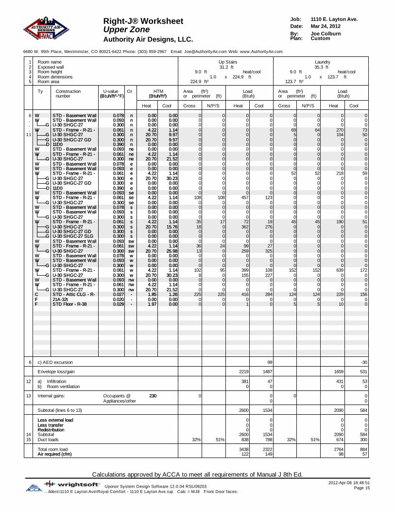
Calculations approved by ACCA to meet all requirements of Manual J 8th Ed.2012-Apr-08 18:48:51
Uponor System Design Software 12.0.04 RSU09203 Page 15...ilders\1110 E Layton Ave\Royal Comfort - 1110 E Layton Ave.rup Calc = MJ8 Front Door faces:
1110 E. Layton Ave.Job:Right-J® WorksheetMar 24, 2012Date:Upper ZoneJoe ColburnBy:CustomPlan:Authority Air Designs, LLC.
6680 W. 95th Place, Westminster, CO 80021-6422 Phone: (303) 859-2967 Email: [email protected] Web: www.AuthorityAir.com
1 Room name Up Stairs Laundry2 Exposed wall 31.2 ft 35.3 ft3 Room height 9.0 heat/coolft 9.0 heat/coolft4 Room dimensions ft224.9x1.0 ft123.7x1.05 Room area 224.9 ft² 123.7 ft²
Ty Construction U-value Or HTM Area (ft²) Load Area (ft²) Loadnumber (Btuh/ft²-°F)(Btuh/ft²-°F) (Btuh/ft²)(Btuh/ft²) or perimeter (ft) (Btuh) or perimeter (ft) (Btuh)
Heat Cool Gross N/P/S Heat Cool Gross N/P/S Heat Cool
6 WW STD - Basement Wall 0.078STD - Basement Wall 0.078 nn 0.000.00 0.000.00 0 0 0 0 0 0 0 0. WW STD - Basement Wall 0.093STD - Basement Wall 0.093 nn 0.000.00 0.000.00 0 0 0 0 0 0 0 0. GG U-30 SHGC-27U-30 SHGC-27 0.3000.300 nn 0.000.00 0.000.00 0 0 0 0 0 0 0 0. WW STD - Frame - R-21 - 0.061STD - Frame - R-21 - 0.061 nn 4.224.22 1.141.14 0 0 0 0 69 64 270 73
11 GG U-30 SHGC-27U-30 SHGC-27 0.3000.300 nn 20.7020.70 9.979.97 0 0 0 0 5 0 104 50GG U-30 SHGC-27 GDU-30 SHGC-27 GD 0.3000.300 nn 20.7020.70 9.979.97 0 0 0 0 0 0 0 0DD 11D011D0 0.3900.390 nn 0.000.00 0.000.00 0 0 0 0 0 0 0 0
WW STD - Basement Wall 0.093STD - Basement Wall 0.093 nene 0.000.00 0.000.00 0 0 0 0 0 0 0 0WW STD - Frame - R-21 - 0.061STD - Frame - R-21 - 0.061 nene 4.224.22 1.141.14 0 0 0 0 0 0 0 0
GG U-30 SHGC-27U-30 SHGC-27 0.3000.300 nene 20.7020.70 21.5221.52 0 0 0 0 0 0 0 0WW STD - Basement Wall 0.078STD - Basement Wall 0.078 ee 0.000.00 0.000.00 0 0 0 0 0 0 0 0WW STD - Basement Wall 0.093STD - Basement Wall 0.093 ee 0.000.00 0.000.00 0 0 0 0 0 0 0 0WW STD - Frame - R-21 - 0.061STD - Frame - R-21 - 0.061 ee 4.224.22 1.141.14 0 0 0 0 52 52 218 59
GG U-30 SHGC-27U-30 SHGC-27 0.3000.300 ee 20.7020.70 30.2330.23 0 0 0 0 0 0 0 0GG U-30 SHGC-27 GDU-30 SHGC-27 GD 0.3000.300 ee 0.000.00 0.000.00 0 0 0 0 0 0 0 0DD 11D011D0 0.3900.390 ee 0.000.00 0.000.00 0 0 0 0 0 0 0 0
WW STD - Basement Wall 0.093STD - Basement Wall 0.093 sese 0.000.00 0.000.00 0 0 0 0 0 0 0 0WW STD - Frame - R-21 - 0.061STD - Frame - R-21 - 0.061 sese 4.224.22 1.141.14 108 108 457 123 0 0 0 0
GG U-30 SHGC-27U-30 SHGC-27 0.3000.300 sese 0.000.00 0.000.00 0 0 0 0 0 0 0 0WW STD - Basement Wall 0.078STD - Basement Wall 0.078 ss 0.000.00 0.000.00 0 0 0 0 0 0 0 0WW STD - Basement Wall 0.093STD - Basement Wall 0.093 ss 0.000.00 0.000.00 0 0 0 0 0 0 0 0
GG U-30 SHGC-27U-30 SHGC-27 0.3000.300 ss 0.000.00 0.000.00 0 0 0 0 0 0 0 0WW STD - Frame - R-21 - 0.061STD - Frame - R-21 - 0.061 ss 4.224.22 1.141.14 35 17 72 19 45 45 190 51
GG U-30 SHGC-27U-30 SHGC-27 0.3000.300 ss 20.7020.70 15.7615.76 18 0 362 276 0 0 0 0GG U-30 SHGC-27 GDU-30 SHGC-27 GD 0.3000.300 ss 0.000.00 0.000.00 0 0 0 0 0 0 0 0GG U-30 SHGC-27 SLGU-30 SHGC-27 SLG 0.3000.300 ss 0.000.00 0.000.00 0 0 0 0 0 0 0 0
WW STD - Basement Wall 0.093STD - Basement Wall 0.093 swsw 0.000.00 0.000.00 0 0 0 0 0 0 0 0WW STD - Frame - R-21 - 0.061STD - Frame - R-21 - 0.061 swsw 4.224.22 1.141.14 36 24 99 27 0 0 0 0
GG U-30 SHGC-27U-30 SHGC-27 0.3000.300 swsw 20.7020.70 25.9825.98 13 0 259 325 0 0 0 0WW STD - Basement Wall 0.078STD - Basement Wall 0.078 ww 0.000.00 0.000.00 0 0 0 0 0 0 0 0WW STD - Basement Wall 0.093STD - Basement Wall 0.093 ww 0.000.00 0.000.00 0 0 0 0 0 0 0 0
GG U-30 SHGC-27U-30 SHGC-27 0.3000.300 ww 0.000.00 0.000.00 0 0 0 0 0 0 0 0WW STD - Frame - R-21 - 0.061STD - Frame - R-21 - 0.061 ww 4.224.22 1.141.14 102 95 399 108 152 152 639 172
GG U-30 SHGC-27U-30 SHGC-27 0.3000.300 ww 20.7020.70 30.2330.23 8 0 155 227 0 0 0 0WW STD - Basement Wall 0.093STD - Basement Wall 0.093 nwnw 0.000.00 0.000.00 0 0 0 0 0 0 0 0WW STD - Frame - R-21 - 0.061STD - Frame - R-21 - 0.061 nwnw 4.224.22 1.141.14 0 0 0 0 0 0 0 0
GG U-30 SHGC-27U-30 SHGC-27 0.3000.300 nwnw 20.7020.70 21.5221.52 0 0 0 0 0 0 0 0CC STD - Attic CLG - R- 0.027STD - Attic CLG - R- 0.027 -- 1.851.85 1.261.26 225 225 416 284 124 124 229 156FF 21A-32t21A-32t 0.0200.020 -- 0.000.00 0.000.00 0 0 0 0 0 0 0 0FF STD Floor - R-38STD Floor - R-38 0.0290.029 -- 1.971.97 0.000.00 0 0 1 0 5 5 10 0
6 c) AED excursion 99 -30
Envelope loss/gain 2219 1487 1659 531
12 a) Infiltration 381 47 431 53b) Room ventilation 0 0 0 0
13 Internal gains: Occupants @ 230230 0 0 0 0Appliances/other 0 0
Subtotal (lines 6 to 13) 2600 1534 2090 584
Less external loadLess external load 0 0 0 0Less transferLess transfer 0 0 0 0RedistributionRedistribution 0 0 0 0
14 Subtotal 2600 1534 2090 58415 Duct loads 32% 51% 838 788 32% 51% 674 300
Total room load 3438 2322 2764 884Air required (cfm)Air required (cfm) 122 149 98 57

Calculations approved by ACCA to meet all requirements of Manual J 8th Ed.2012-Apr-08 18:48:51
Uponor System Design Software 12.0.04 RSU09203 Page 16...ilders\1110 E Layton Ave\Royal Comfort - 1110 E Layton Ave.rup Calc = MJ8 Front Door faces:
1110 E. Layton Ave.Job:Right-J® WorksheetMar 24, 2012Date:Upper ZoneJoe ColburnBy:CustomPlan:Authority Air Designs, LLC.
6680 W. 95th Place, Westminster, CO 80021-6422 Phone: (303) 859-2967 Email: [email protected] Web: www.AuthorityAir.com
1 Room name D Bedroom D Bath2 Exposed wall 28.0 ft 3.6 ft3 Room height 10.0 heat/coolft 9.0 heat/coolft4 Room dimensions ft195.6x1.0 ft94.2x1.05 Room area 195.6 ft² 94.2 ft²
Ty Construction U-value Or HTM Area (ft²) Load Area (ft²) Loadnumber (Btuh/ft²-°F)(Btuh/ft²-°F) (Btuh/ft²)(Btuh/ft²) or perimeter (ft) (Btuh) or perimeter (ft) (Btuh)
Heat Cool Gross N/P/S Heat Cool Gross N/P/S Heat Cool
6 WW STD - Basement Wall 0.078STD - Basement Wall 0.078 nn 0.000.00 0.000.00 0 0 0 0 0 0 0 0. WW STD - Basement Wall 0.093STD - Basement Wall 0.093 nn 0.000.00 0.000.00 0 0 0 0 0 0 0 0. GG U-30 SHGC-27U-30 SHGC-27 0.3000.300 nn 0.000.00 0.000.00 0 0 0 0 0 0 0 0. WW STD - Frame - R-21 - 0.061STD - Frame - R-21 - 0.061 nn 4.224.22 1.141.14 145 105 442 119 32 32 136 37
11 GG U-30 SHGC-27U-30 SHGC-27 0.3000.300 nn 20.7020.70 9.979.97 0 0 0 0 0 0 0 0GG U-30 SHGC-27 GDU-30 SHGC-27 GD 0.3000.300 nn 20.7020.70 9.979.97 40 0 832 401 0 0 0 0DD 11D011D0 0.3900.390 nn 0.000.00 0.000.00 0 0 0 0 0 0 0 0
WW STD - Basement Wall 0.093STD - Basement Wall 0.093 nene 0.000.00 0.000.00 0 0 0 0 0 0 0 0WW STD - Frame - R-21 - 0.061STD - Frame - R-21 - 0.061 nene 4.224.22 1.141.14 0 0 0 0 0 0 0 0
GG U-30 SHGC-27U-30 SHGC-27 0.3000.300 nene 20.7020.70 21.5221.52 0 0 0 0 0 0 0 0WW STD - Basement Wall 0.078STD - Basement Wall 0.078 ee 0.000.00 0.000.00 0 0 0 0 0 0 0 0WW STD - Basement Wall 0.093STD - Basement Wall 0.093 ee 0.000.00 0.000.00 0 0 0 0 0 0 0 0WW STD - Frame - R-21 - 0.061STD - Frame - R-21 - 0.061 ee 4.224.22 1.141.14 20 20 84 23 0 0 0 0
GG U-30 SHGC-27U-30 SHGC-27 0.3000.300 ee 20.7020.70 30.2330.23 0 0 0 0 0 0 0 0GG U-30 SHGC-27 GDU-30 SHGC-27 GD 0.3000.300 ee 0.000.00 0.000.00 0 0 0 0 0 0 0 0DD 11D011D0 0.3900.390 ee 0.000.00 0.000.00 0 0 0 0 0 0 0 0
WW STD - Basement Wall 0.093STD - Basement Wall 0.093 sese 0.000.00 0.000.00 0 0 0 0 0 0 0 0WW STD - Frame - R-21 - 0.061STD - Frame - R-21 - 0.061 sese 4.224.22 1.141.14 0 0 0 0 0 0 0 0
GG U-30 SHGC-27U-30 SHGC-27 0.3000.300 sese 0.000.00 0.000.00 0 0 0 0 0 0 0 0WW STD - Basement Wall 0.078STD - Basement Wall 0.078 ss 0.000.00 0.000.00 0 0 0 0 0 0 0 0WW STD - Basement Wall 0.093STD - Basement Wall 0.093 ss 0.000.00 0.000.00 0 0 0 0 0 0 0 0
GG U-30 SHGC-27U-30 SHGC-27 0.3000.300 ss 0.000.00 0.000.00 0 0 0 0 0 0 0 0WW STD - Frame - R-21 - 0.061STD - Frame - R-21 - 0.061 ss 4.224.22 1.141.14 0 0 0 0 0 0 0 0
GG U-30 SHGC-27U-30 SHGC-27 0.3000.300 ss 20.7020.70 15.7615.76 0 0 0 0 0 0 0 0GG U-30 SHGC-27 GDU-30 SHGC-27 GD 0.3000.300 ss 0.000.00 0.000.00 0 0 0 0 0 0 0 0GG U-30 SHGC-27 SLGU-30 SHGC-27 SLG 0.3000.300 ss 0.000.00 0.000.00 0 0 0 0 0 0 0 0
WW STD - Basement Wall 0.093STD - Basement Wall 0.093 swsw 0.000.00 0.000.00 0 0 0 0 0 0 0 0WW STD - Frame - R-21 - 0.061STD - Frame - R-21 - 0.061 swsw 4.224.22 1.141.14 0 0 0 0 0 0 0 0
GG U-30 SHGC-27U-30 SHGC-27 0.3000.300 swsw 20.7020.70 25.9825.98 0 0 0 0 0 0 0 0WW STD - Basement Wall 0.078STD - Basement Wall 0.078 ww 0.000.00 0.000.00 0 0 0 0 0 0 0 0WW STD - Basement Wall 0.093STD - Basement Wall 0.093 ww 0.000.00 0.000.00 0 0 0 0 0 0 0 0
GG U-30 SHGC-27U-30 SHGC-27 0.3000.300 ww 0.000.00 0.000.00 0 0 0 0 0 0 0 0WW STD - Frame - R-21 - 0.061STD - Frame - R-21 - 0.061 ww 4.224.22 1.141.14 115 115 485 131 0 0 0 0
GG U-30 SHGC-27U-30 SHGC-27 0.3000.300 ww 20.7020.70 30.2330.23 0 0 0 0 0 0 0 0WW STD - Basement Wall 0.093STD - Basement Wall 0.093 nwnw 0.000.00 0.000.00 0 0 0 0 0 0 0 0WW STD - Frame - R-21 - 0.061STD - Frame - R-21 - 0.061 nwnw 4.224.22 1.141.14 0 0 0 0 0 0 0 0
GG U-30 SHGC-27U-30 SHGC-27 0.3000.300 nwnw 20.7020.70 21.5221.52 0 0 0 0 0 0 0 0CC STD - Attic CLG - R- 0.027STD - Attic CLG - R- 0.027 -- 1.851.85 1.261.26 196 196 361 247 94 94 174 119FF 21A-32t21A-32t 0.0200.020 -- 0.000.00 0.000.00 0 0 0 0 0 0 0 0FF STD Floor - R-38STD Floor - R-38 0.0290.029 -- 1.971.97 0.000.00 0 0 0 0 0 0 0 0
6 c) AED excursion -59 -8
Envelope loss/gain 2206 861 310 148
12 a) Infiltration 380 47 44 5b) Room ventilation 0 0 0 0
13 Internal gains: Occupants @ 230230 1 230 0 0Appliances/other 0 0
Subtotal (lines 6 to 13) 2586 1138 354 153
Less external loadLess external load 0 0 0 0Less transferLess transfer 0 0 0 0RedistributionRedistribution 0 0 0 0
14 Subtotal 2586 1138 354 15315 Duct loads 32% 51% 833 585 32% 51% 114 79
Total room load 3419 1723 468 232Air required (cfm)Air required (cfm) 121 110 17 15

Calculations approved by ACCA to meet all requirements of Manual J 8th Ed.2012-Apr-08 18:48:51
Uponor System Design Software 12.0.04 RSU09203 Page 17...ilders\1110 E Layton Ave\Royal Comfort - 1110 E Layton Ave.rup Calc = MJ8 Front Door faces:
1110 E. Layton Ave.Job:Right-J® WorksheetMar 24, 2012Date:East ZoneJoe ColburnBy:CustomPlan:Authority Air Designs, LLC.
6680 W. 95th Place, Westminster, CO 80021-6422 Phone: (303) 859-2967 Email: [email protected] Web: www.AuthorityAir.com
1 Room name East Zone M Spa2 Exposed wall 162.2 ft 28.8 ft3 Room height 11.1 pft 14.0 heat/coolft4 Room dimensions ft335.7x1.05 Room area 1661.6 ft² 335.7 ft²
Ty Construction U-value Or HTM Area (ft²) Load Area (ft²) Loadnumber (Btuh/ft²-°F)(Btuh/ft²-°F) (Btuh/ft²)(Btuh/ft²) or perimeter (ft) (Btuh) or perimeter (ft) (Btuh)
Heat Cool Gross N/P/S Heat Cool Gross N/P/S Heat Cool
6 WW STD - Basement Wall 0.078STD - Basement Wall 0.078 nn 0.000.00 0.000.00 0 0 0 0 0 0 0 0. WW STD - Basement Wall 0.093STD - Basement Wall 0.093 nn 0.000.00 0.000.00 0 0 0 0 0 0 0 0. GG U-30 SHGC-27U-30 SHGC-27 0.3000.300 nn 0.000.00 0.000.00 0 0 0 0 0 0 0 0. WW STD - Frame - R-21 - 0.061STD - Frame - R-21 - 0.061 nn 4.224.22 1.141.14 553 483 2037 549 230 203 855 230
11 GG U-30 SHGC-27U-30 SHGC-27 0.3000.300 nn 20.7020.70 9.979.97 71 0 1465 705 27 0 564 272GG U-30 SHGC-27 GDU-30 SHGC-27 GD 0.3000.300 nn 0.000.00 0.000.00 0 0 0 0 0 0 0 0DD 11D011D0 0.3900.390 nn 0.000.00 0.000.00 0 0 0 0 0 0 0 0
WW STD - Basement Wall 0.093STD - Basement Wall 0.093 nene 0.000.00 0.000.00 0 0 0 0 0 0 0 0WW STD - Frame - R-21 - 0.061STD - Frame - R-21 - 0.061 nene 0.000.00 0.000.00 0 0 0 0 0 0 0 0
GG U-30 SHGC-27U-30 SHGC-27 0.3000.300 nene 0.000.00 0.000.00 0 0 0 0 0 0 0 0WW STD - Basement Wall 0.078STD - Basement Wall 0.078 ee 0.000.00 0.000.00 0 0 0 0 0 0 0 0WW STD - Basement Wall 0.093STD - Basement Wall 0.093 ee 0.000.00 0.000.00 0 0 0 0 0 0 0 0WW STD - Frame - R-21 - 0.061STD - Frame - R-21 - 0.061 ee 4.224.22 1.141.14 142 137 577 155 15 15 64 17
GG U-30 SHGC-27U-30 SHGC-27 0.3000.300 ee 20.7020.70 30.2330.23 5 0 109 159 0 0 0 0GG U-30 SHGC-27 GDU-30 SHGC-27 GD 0.3000.300 ee 0.000.00 0.000.00 0 0 0 0 0 0 0 0DD 11D011D0 0.3900.390 ee 0.000.00 0.000.00 0 0 0 0 0 0 0 0
WW STD - Basement Wall 0.093STD - Basement Wall 0.093 sese 0.000.00 0.000.00 0 0 0 0 0 0 0 0WW STD - Frame - R-21 - 0.061STD - Frame - R-21 - 0.061 sese 4.224.22 1.141.14 38 28 119 32 0 0 0 0
GG U-30 SHGC-27U-30 SHGC-27 0.3000.300 sese 20.7020.70 25.9825.98 10 0 207 260 0 0 0 0WW STD - Basement Wall 0.078STD - Basement Wall 0.078 ss 0.000.00 0.000.00 0 0 0 0 0 0 0 0WW STD - Basement Wall 0.093STD - Basement Wall 0.093 ss 0.000.00 0.000.00 0 0 0 0 0 0 0 0
GG U-30 SHGC-27U-30 SHGC-27 0.3000.300 ss 0.000.00 0.000.00 0 0 0 0 0 0 0 0WW STD - Frame - R-21 - 0.061STD - Frame - R-21 - 0.061 ss 4.224.22 1.141.14 427 357 1505 406 0 0 0 0
GG U-30 SHGC-27U-30 SHGC-27 0.3000.300 ss 20.7020.70 15.7615.76 31 0 631 481 0 0 0 0GG U-30 SHGC-27 GDU-30 SHGC-27 GD 0.3000.300 ss 20.7020.70 15.7615.76 40 0 828 630 0 0 0 0GG U-30 SHGC-27 SLGU-30 SHGC-27 SLG 0.3000.300 ss 0.000.00 0.000.00 0 0 0 0 0 0 0 0
WW STD - Basement Wall 0.093STD - Basement Wall 0.093 swsw 0.000.00 0.000.00 0 0 0 0 0 0 0 0WW STD - Frame - R-21 - 0.061STD - Frame - R-21 - 0.061 swsw 4.224.22 1.141.14 39 29 122 33 0 0 0 0
GG U-30 SHGC-27U-30 SHGC-27 0.3000.300 swsw 20.7020.70 25.9825.98 10 0 207 260 0 0 0 0WW STD - Basement Wall 0.078STD - Basement Wall 0.078 ww 0.000.00 0.000.00 0 0 0 0 0 0 0 0WW STD - Basement Wall 0.093STD - Basement Wall 0.093 ww 0.000.00 0.000.00 0 0 0 0 0 0 0 0
GG U-30 SHGC-27U-30 SHGC-27 0.3000.300 ww 0.000.00 0.000.00 0 0 0 0 0 0 0 0WW STD - Frame - R-21 - 0.061STD - Frame - R-21 - 0.061 ww 4.224.22 1.141.14 628 570 2405 648 159 153 647 175
GG U-30 SHGC-27U-30 SHGC-27 0.3000.300 ww 20.7020.70 30.2330.23 58 0 1201 1753 5 0 109 159WW STD - Basement Wall 0.093STD - Basement Wall 0.093 nwnw 0.000.00 0.000.00 0 0 0 0 0 0 0 0WW STD - Frame - R-21 - 0.061STD - Frame - R-21 - 0.061 nwnw 0.000.00 0.000.00 0 0 0 0 0 0 0 0
GG U-30 SHGC-27U-30 SHGC-27 0.3000.300 nwnw 0.000.00 0.000.00 0 0 0 0 0 0 0 0CC STD - Attic CLG - R- 0.027STD - Attic CLG - R- 0.027 -- 1.851.85 1.261.26 994 994 1837 1254 295 295 545 372FF 21A-32t21A-32t 0.0200.020 -- 0.000.00 0.000.00 0 0 0 0 0 0 0 0FF STD Floor - R-38STD Floor - R-38 0.0290.029 -- 0.000.00 0.000.00 0 0 0 0 0 0 0 0
6 c) AED excursion 1919 121
Envelope loss/gain 13249 9245 2784 1345
12 a) Infiltration 2483 306 548 68b) Room ventilation 0 0 0 0
13 Internal gains: Occupants @ 230230 2 460 0 0Appliances/other 0 0
Subtotal (lines 6 to 13) 15732 10011 3332 1413
Less external loadLess external load 0 0 0 0Less transferLess transfer 0 0 0 0RedistributionRedistribution 0 0 0 0
14 Subtotal 15732 10011 3332 141315 Duct loads 0% 0% 0 0 -0% 0% 0 0
Total room load 15732 10011 3332 1413Air required (cfm)Air required (cfm) 696 734 148 104

Calculations approved by ACCA to meet all requirements of Manual J 8th Ed.2012-Apr-08 18:48:51
Uponor System Design Software 12.0.04 RSU09203 Page 18...ilders\1110 E Layton Ave\Royal Comfort - 1110 E Layton Ave.rup Calc = MJ8 Front Door faces:
1110 E. Layton Ave.Job:Right-J® WorksheetMar 24, 2012Date:East ZoneJoe ColburnBy:CustomPlan:Authority Air Designs, LLC.
6680 W. 95th Place, Westminster, CO 80021-6422 Phone: (303) 859-2967 Email: [email protected] Web: www.AuthorityAir.com
1 Room name M WC M WIC 22 Exposed wall 10.2 ft 21.9 ft3 Room height 9.0 heat/coolft 9.0 heat/coolft4 Room dimensions ft6.4x3.8 ft125.3x1.05 Room area 24.1 ft² 125.3 ft²
Ty Construction U-value Or HTM Area (ft²) Load Area (ft²) Loadnumber (Btuh/ft²-°F)(Btuh/ft²-°F) (Btuh/ft²)(Btuh/ft²) or perimeter (ft) (Btuh) or perimeter (ft) (Btuh)
Heat Cool Gross N/P/S Heat Cool Gross N/P/S Heat Cool
6 WW STD - Basement Wall 0.078STD - Basement Wall 0.078 nn 0.000.00 0.000.00 0 0 0 0 0 0 0 0. WW STD - Basement Wall 0.093STD - Basement Wall 0.093 nn 0.000.00 0.000.00 0 0 0 0 0 0 0 0. GG U-30 SHGC-27U-30 SHGC-27 0.3000.300 nn 0.000.00 0.000.00 0 0 0 0 0 0 0 0. WW STD - Frame - R-21 - 0.061STD - Frame - R-21 - 0.061 nn 4.224.22 1.141.14 34 34 142 38 36 36 152 41
11 GG U-30 SHGC-27U-30 SHGC-27 0.3000.300 nn 20.7020.70 9.979.97 0 0 0 0 0 0 0 0GG U-30 SHGC-27 GDU-30 SHGC-27 GD 0.3000.300 nn 0.000.00 0.000.00 0 0 0 0 0 0 0 0DD 11D011D0 0.3900.390 nn 0.000.00 0.000.00 0 0 0 0 0 0 0 0
WW STD - Basement Wall 0.093STD - Basement Wall 0.093 nene 0.000.00 0.000.00 0 0 0 0 0 0 0 0WW STD - Frame - R-21 - 0.061STD - Frame - R-21 - 0.061 nene 0.000.00 0.000.00 0 0 0 0 0 0 0 0
GG U-30 SHGC-27U-30 SHGC-27 0.3000.300 nene 0.000.00 0.000.00 0 0 0 0 0 0 0 0WW STD - Basement Wall 0.078STD - Basement Wall 0.078 ee 0.000.00 0.000.00 0 0 0 0 0 0 0 0WW STD - Basement Wall 0.093STD - Basement Wall 0.093 ee 0.000.00 0.000.00 0 0 0 0 0 0 0 0WW STD - Frame - R-21 - 0.061STD - Frame - R-21 - 0.061 ee 4.224.22 1.141.14 58 53 222 60 0 0 0 0
GG U-30 SHGC-27U-30 SHGC-27 0.3000.300 ee 20.7020.70 30.2330.23 5 0 109 159 0 0 0 0GG U-30 SHGC-27 GDU-30 SHGC-27 GD 0.3000.300 ee 0.000.00 0.000.00 0 0 0 0 0 0 0 0DD 11D011D0 0.3900.390 ee 0.000.00 0.000.00 0 0 0 0 0 0 0 0
WW STD - Basement Wall 0.093STD - Basement Wall 0.093 sese 0.000.00 0.000.00 0 0 0 0 0 0 0 0WW STD - Frame - R-21 - 0.061STD - Frame - R-21 - 0.061 sese 4.224.22 1.141.14 0 0 0 0 0 0 0 0
GG U-30 SHGC-27U-30 SHGC-27 0.3000.300 sese 20.7020.70 25.9825.98 0 0 0 0 0 0 0 0WW STD - Basement Wall 0.078STD - Basement Wall 0.078 ss 0.000.00 0.000.00 0 0 0 0 0 0 0 0WW STD - Basement Wall 0.093STD - Basement Wall 0.093 ss 0.000.00 0.000.00 0 0 0 0 0 0 0 0
GG U-30 SHGC-27U-30 SHGC-27 0.3000.300 ss 0.000.00 0.000.00 0 0 0 0 0 0 0 0WW STD - Frame - R-21 - 0.061STD - Frame - R-21 - 0.061 ss 4.224.22 1.141.14 0 0 0 0 63 63 266 72
GG U-30 SHGC-27U-30 SHGC-27 0.3000.300 ss 20.7020.70 15.7615.76 0 0 0 0 0 0 0 0GG U-30 SHGC-27 GDU-30 SHGC-27 GD 0.3000.300 ss 20.7020.70 15.7615.76 0 0 0 0 0 0 0 0GG U-30 SHGC-27 SLGU-30 SHGC-27 SLG 0.3000.300 ss 0.000.00 0.000.00 0 0 0 0 0 0 0 0
WW STD - Basement Wall 0.093STD - Basement Wall 0.093 swsw 0.000.00 0.000.00 0 0 0 0 0 0 0 0WW STD - Frame - R-21 - 0.061STD - Frame - R-21 - 0.061 swsw 4.224.22 1.141.14 0 0 0 0 0 0 0 0
GG U-30 SHGC-27U-30 SHGC-27 0.3000.300 swsw 20.7020.70 25.9825.98 0 0 0 0 0 0 0 0WW STD - Basement Wall 0.078STD - Basement Wall 0.078 ww 0.000.00 0.000.00 0 0 0 0 0 0 0 0WW STD - Basement Wall 0.093STD - Basement Wall 0.093 ww 0.000.00 0.000.00 0 0 0 0 0 0 0 0
GG U-30 SHGC-27U-30 SHGC-27 0.3000.300 ww 0.000.00 0.000.00 0 0 0 0 0 0 0 0WW STD - Frame - R-21 - 0.061STD - Frame - R-21 - 0.061 ww 4.224.22 1.141.14 0 0 0 0 98 92 388 105
GG U-30 SHGC-27U-30 SHGC-27 0.3000.300 ww 20.7020.70 30.2330.23 0 0 0 0 6 0 129 189WW STD - Basement Wall 0.093STD - Basement Wall 0.093 nwnw 0.000.00 0.000.00 0 0 0 0 0 0 0 0WW STD - Frame - R-21 - 0.061STD - Frame - R-21 - 0.061 nwnw 0.000.00 0.000.00 0 0 0 0 0 0 0 0
GG U-30 SHGC-27U-30 SHGC-27 0.3000.300 nwnw 0.000.00 0.000.00 0 0 0 0 0 0 0 0CC STD - Attic CLG - R- 0.027STD - Attic CLG - R- 0.027 -- 1.851.85 1.261.26 24 24 44 30 125 125 231 158FF 21A-32t21A-32t 0.0200.020 -- 0.000.00 0.000.00 0 0 0 0 0 0 0 0FF STD Floor - R-38STD Floor - R-38 0.0290.029 -- 0.000.00 0.000.00 0 0 0 0 0 0 0 0
6 c) AED excursion 43 89
Envelope loss/gain 517 330 1167 654
12 a) Infiltration 124 15 268 33b) Room ventilation 0 0 0 0
13 Internal gains: Occupants @ 230230 0 0 0 0Appliances/other 0 0
Subtotal (lines 6 to 13) 641 345 1435 687
Less external loadLess external load 0 0 0 0Less transferLess transfer 0 0 0 0RedistributionRedistribution 0 0 0 0
14 Subtotal 641 345 1435 68715 Duct loads -0% 0% 0 0 -0% 0% 0 0
Total room load 641 345 1435 687Air required (cfm)Air required (cfm) 28 25 64 50

Calculations approved by ACCA to meet all requirements of Manual J 8th Ed.2012-Apr-08 18:48:51
Uponor System Design Software 12.0.04 RSU09203 Page 19...ilders\1110 E Layton Ave\Royal Comfort - 1110 E Layton Ave.rup Calc = MJ8 Front Door faces:
1110 E. Layton Ave.Job:Right-J® WorksheetMar 24, 2012Date:East ZoneJoe ColburnBy:CustomPlan:Authority Air Designs, LLC.
6680 W. 95th Place, Westminster, CO 80021-6422 Phone: (303) 859-2967 Email: [email protected] Web: www.AuthorityAir.com
1 Room name M Suite Powder 22 Exposed wall 52.5 ft 5.4 ft3 Room height 12.0 heat/coolft 9.0 heat/coolft4 Room dimensions ft408.3x1.0 ft14.8x5.95 Room area 408.3 ft² 87.3 ft²
Ty Construction U-value Or HTM Area (ft²) Load Area (ft²) Loadnumber (Btuh/ft²-°F)(Btuh/ft²-°F) (Btuh/ft²)(Btuh/ft²) or perimeter (ft) (Btuh) or perimeter (ft) (Btuh)
Heat Cool Gross N/P/S Heat Cool Gross N/P/S Heat Cool
6 WW STD - Basement Wall 0.078STD - Basement Wall 0.078 nn 0.000.00 0.000.00 0 0 0 0 0 0 0 0. WW STD - Basement Wall 0.093STD - Basement Wall 0.093 nn 0.000.00 0.000.00 0 0 0 0 0 0 0 0. GG U-30 SHGC-27U-30 SHGC-27 0.3000.300 nn 0.000.00 0.000.00 0 0 0 0 0 0 0 0. WW STD - Frame - R-21 - 0.061STD - Frame - R-21 - 0.061 nn 4.224.22 1.141.14 60 60 253 68 49 43 180 49
11 GG U-30 SHGC-27U-30 SHGC-27 0.3000.300 nn 20.7020.70 9.979.97 0 0 0 0 6 0 124 60GG U-30 SHGC-27 GDU-30 SHGC-27 GD 0.3000.300 nn 0.000.00 0.000.00 0 0 0 0 0 0 0 0DD 11D011D0 0.3900.390 nn 0.000.00 0.000.00 0 0 0 0 0 0 0 0
WW STD - Basement Wall 0.093STD - Basement Wall 0.093 nene 0.000.00 0.000.00 0 0 0 0 0 0 0 0WW STD - Frame - R-21 - 0.061STD - Frame - R-21 - 0.061 nene 0.000.00 0.000.00 0 0 0 0 0 0 0 0
GG U-30 SHGC-27U-30 SHGC-27 0.3000.300 nene 0.000.00 0.000.00 0 0 0 0 0 0 0 0WW STD - Basement Wall 0.078STD - Basement Wall 0.078 ee 0.000.00 0.000.00 0 0 0 0 0 0 0 0WW STD - Basement Wall 0.093STD - Basement Wall 0.093 ee 0.000.00 0.000.00 0 0 0 0 0 0 0 0WW STD - Frame - R-21 - 0.061STD - Frame - R-21 - 0.061 ee 4.224.22 1.141.14 24 24 101 27 0 0 0 0
GG U-30 SHGC-27U-30 SHGC-27 0.3000.300 ee 20.7020.70 30.2330.23 0 0 0 0 0 0 0 0GG U-30 SHGC-27 GDU-30 SHGC-27 GD 0.3000.300 ee 0.000.00 0.000.00 0 0 0 0 0 0 0 0DD 11D011D0 0.3900.390 ee 0.000.00 0.000.00 0 0 0 0 0 0 0 0
WW STD - Basement Wall 0.093STD - Basement Wall 0.093 sese 0.000.00 0.000.00 0 0 0 0 0 0 0 0WW STD - Frame - R-21 - 0.061STD - Frame - R-21 - 0.061 sese 4.224.22 1.141.14 38 28 119 32 0 0 0 0
GG U-30 SHGC-27U-30 SHGC-27 0.3000.300 sese 20.7020.70 25.9825.98 10 0 207 260 0 0 0 0WW STD - Basement Wall 0.078STD - Basement Wall 0.078 ss 0.000.00 0.000.00 0 0 0 0 0 0 0 0WW STD - Basement Wall 0.093STD - Basement Wall 0.093 ss 0.000.00 0.000.00 0 0 0 0 0 0 0 0
GG U-30 SHGC-27U-30 SHGC-27 0.3000.300 ss 0.000.00 0.000.00 0 0 0 0 0 0 0 0WW STD - Frame - R-21 - 0.061STD - Frame - R-21 - 0.061 ss 4.224.22 1.141.14 205 165 696 188 0 0 0 0
GG U-30 SHGC-27U-30 SHGC-27 0.3000.300 ss 20.7020.70 15.7615.76 0 0 0 0 0 0 0 0GG U-30 SHGC-27 GDU-30 SHGC-27 GD 0.3000.300 ss 20.7020.70 15.7615.76 40 0 828 630 0 0 0 0GG U-30 SHGC-27 SLGU-30 SHGC-27 SLG 0.3000.300 ss 0.000.00 0.000.00 0 0 0 0 0 0 0 0
WW STD - Basement Wall 0.093STD - Basement Wall 0.093 swsw 0.000.00 0.000.00 0 0 0 0 0 0 0 0WW STD - Frame - R-21 - 0.061STD - Frame - R-21 - 0.061 swsw 4.224.22 1.141.14 39 29 122 33 0 0 0 0
GG U-30 SHGC-27U-30 SHGC-27 0.3000.300 swsw 20.7020.70 25.9825.98 10 0 207 260 0 0 0 0WW STD - Basement Wall 0.078STD - Basement Wall 0.078 ww 0.000.00 0.000.00 0 0 0 0 0 0 0 0WW STD - Basement Wall 0.093STD - Basement Wall 0.093 ww 0.000.00 0.000.00 0 0 0 0 0 0 0 0
GG U-30 SHGC-27U-30 SHGC-27 0.3000.300 ww 0.000.00 0.000.00 0 0 0 0 0 0 0 0WW STD - Frame - R-21 - 0.061STD - Frame - R-21 - 0.061 ww 4.224.22 1.141.14 264 227 956 258 0 0 0 0
GG U-30 SHGC-27U-30 SHGC-27 0.3000.300 ww 20.7020.70 30.2330.23 38 0 776 1134 0 0 0 0WW STD - Basement Wall 0.093STD - Basement Wall 0.093 nwnw 0.000.00 0.000.00 0 0 0 0 0 0 0 0WW STD - Frame - R-21 - 0.061STD - Frame - R-21 - 0.061 nwnw 0.000.00 0.000.00 0 0 0 0 0 0 0 0
GG U-30 SHGC-27U-30 SHGC-27 0.3000.300 nwnw 0.000.00 0.000.00 0 0 0 0 0 0 0 0CC STD - Attic CLG - R- 0.027STD - Attic CLG - R- 0.027 -- 1.851.85 1.261.26 400 400 738 504 43 43 79 54FF 21A-32t21A-32t 0.0200.020 -- 0.000.00 0.000.00 0 0 0 0 0 0 0 0FF STD Floor - R-38STD Floor - R-38 0.0290.029 -- 0.000.00 0.000.00 0 0 0 0 0 0 0 0
6 c) AED excursion 1001 18
Envelope loss/gain 5004 4395 384 180
12 a) Infiltration 856 106 66 8b) Room ventilation 0 0 0 0
13 Internal gains: Occupants @ 230230 2 460 0 0Appliances/other 0 0
Subtotal (lines 6 to 13) 5860 4960 450 188
Less external loadLess external load 0 0 0 0Less transferLess transfer 0 0 0 0RedistributionRedistribution 0 0 0 0
14 Subtotal 5860 4960 450 18815 Duct loads -0% 0% 0 0 -0% 0% 0 0
Total room load 5860 4960 450 188Air required (cfm)Air required (cfm) 259 364 20 14
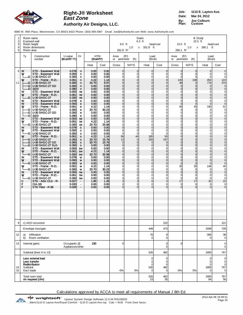
Calculations approved by ACCA to meet all requirements of Manual J 8th Ed.2012-Apr-08 18:48:51
Uponor System Design Software 12.0.04 RSU09203 Page 20...ilders\1110 E Layton Ave\Royal Comfort - 1110 E Layton Ave.rup Calc = MJ8 Front Door faces:
1110 E. Layton Ave.Job:Right-J® WorksheetMar 24, 2012Date:East ZoneJoe ColburnBy:CustomPlan:Authority Air Designs, LLC.
6680 W. 95th Place, Westminster, CO 80021-6422 Phone: (303) 859-2967 Email: [email protected] Web: www.AuthorityAir.com
1 Room name Stairs B Study2 Exposed wall 6.3 ft 22.5 ft3 Room height 9.0 heat/coolft 10.0 heat/coolft4 Room dimensions ft331.8x1.0 ft260.1x1.05 Room area 331.8 ft² 260.1 ft²
Ty Construction U-value Or HTM Area (ft²) Load Area (ft²) Loadnumber (Btuh/ft²-°F)(Btuh/ft²-°F) (Btuh/ft²)(Btuh/ft²) or perimeter (ft) (Btuh) or perimeter (ft) (Btuh)
Heat Cool Gross N/P/S Heat Cool Gross N/P/S Heat Cool
6 WW STD - Basement Wall 0.078STD - Basement Wall 0.078 nn 0.000.00 0.000.00 0 0 0 0 0 0 0 0. WW STD - Basement Wall 0.093STD - Basement Wall 0.093 nn 0.000.00 0.000.00 0 0 0 0 0 0 0 0. GG U-30 SHGC-27U-30 SHGC-27 0.3000.300 nn 0.000.00 0.000.00 0 0 0 0 0 0 0 0. WW STD - Frame - R-21 - 0.061STD - Frame - R-21 - 0.061 nn 4.224.22 1.141.14 0 0 0 0 145 108 454 122
11 GG U-30 SHGC-27U-30 SHGC-27 0.3000.300 nn 20.7020.70 9.979.97 0 0 0 0 38 0 776 374GG U-30 SHGC-27 GDU-30 SHGC-27 GD 0.3000.300 nn 0.000.00 0.000.00 0 0 0 0 0 0 0 0DD 11D011D0 0.3900.390 nn 0.000.00 0.000.00 0 0 0 0 0 0 0 0
WW STD - Basement Wall 0.093STD - Basement Wall 0.093 nene 0.000.00 0.000.00 0 0 0 0 0 0 0 0WW STD - Frame - R-21 - 0.061STD - Frame - R-21 - 0.061 nene 0.000.00 0.000.00 0 0 0 0 0 0 0 0
GG U-30 SHGC-27U-30 SHGC-27 0.3000.300 nene 0.000.00 0.000.00 0 0 0 0 0 0 0 0WW STD - Basement Wall 0.078STD - Basement Wall 0.078 ee 0.000.00 0.000.00 0 0 0 0 0 0 0 0WW STD - Basement Wall 0.093STD - Basement Wall 0.093 ee 0.000.00 0.000.00 0 0 0 0 0 0 0 0WW STD - Frame - R-21 - 0.061STD - Frame - R-21 - 0.061 ee 4.224.22 1.141.14 0 0 0 0 45 45 190 51
GG U-30 SHGC-27U-30 SHGC-27 0.3000.300 ee 20.7020.70 30.2330.23 0 0 0 0 0 0 0 0GG U-30 SHGC-27 GDU-30 SHGC-27 GD 0.3000.300 ee 0.000.00 0.000.00 0 0 0 0 0 0 0 0DD 11D011D0 0.3900.390 ee 0.000.00 0.000.00 0 0 0 0 0 0 0 0
WW STD - Basement Wall 0.093STD - Basement Wall 0.093 sese 0.000.00 0.000.00 0 0 0 0 0 0 0 0WW STD - Frame - R-21 - 0.061STD - Frame - R-21 - 0.061 sese 4.224.22 1.141.14 0 0 0 0 0 0 0 0
GG U-30 SHGC-27U-30 SHGC-27 0.3000.300 sese 20.7020.70 25.9825.98 0 0 0 0 0 0 0 0WW STD - Basement Wall 0.078STD - Basement Wall 0.078 ss 0.000.00 0.000.00 0 0 0 0 0 0 0 0WW STD - Basement Wall 0.093STD - Basement Wall 0.093 ss 0.000.00 0.000.00 0 0 0 0 0 0 0 0
GG U-30 SHGC-27U-30 SHGC-27 0.3000.300 ss 0.000.00 0.000.00 0 0 0 0 0 0 0 0WW STD - Frame - R-21 - 0.061STD - Frame - R-21 - 0.061 ss 4.224.22 1.141.14 56 44 185 50 0 0 0 0
GG U-30 SHGC-27U-30 SHGC-27 0.3000.300 ss 20.7020.70 15.7615.76 13 0 259 197 0 0 0 0GG U-30 SHGC-27 GDU-30 SHGC-27 GD 0.3000.300 ss 20.7020.70 15.7615.76 0 0 0 0 0 0 0 0GG U-30 SHGC-27 SLGU-30 SHGC-27 SLG 0.3000.300 ss 0.000.00 0.000.00 0 0 0 0 0 0 0 0
WW STD - Basement Wall 0.093STD - Basement Wall 0.093 swsw 0.000.00 0.000.00 0 0 0 0 0 0 0 0WW STD - Frame - R-21 - 0.061STD - Frame - R-21 - 0.061 swsw 4.224.22 1.141.14 0 0 0 0 0 0 0 0
GG U-30 SHGC-27U-30 SHGC-27 0.3000.300 swsw 20.7020.70 25.9825.98 0 0 0 0 0 0 0 0WW STD - Basement Wall 0.078STD - Basement Wall 0.078 ww 0.000.00 0.000.00 0 0 0 0 0 0 0 0WW STD - Basement Wall 0.093STD - Basement Wall 0.093 ww 0.000.00 0.000.00 0 0 0 0 0 0 0 0
GG U-30 SHGC-27U-30 SHGC-27 0.3000.300 ww 0.000.00 0.000.00 0 0 0 0 0 0 0 0WW STD - Frame - R-21 - 0.061STD - Frame - R-21 - 0.061 ww 4.224.22 1.141.14 0 0 0 0 35 35 148 40
GG U-30 SHGC-27U-30 SHGC-27 0.3000.300 ww 20.7020.70 30.2330.23 0 0 0 0 0 0 0 0WW STD - Basement Wall 0.093STD - Basement Wall 0.093 nwnw 0.000.00 0.000.00 0 0 0 0 0 0 0 0WW STD - Frame - R-21 - 0.061STD - Frame - R-21 - 0.061 nwnw 0.000.00 0.000.00 0 0 0 0 0 0 0 0
GG U-30 SHGC-27U-30 SHGC-27 0.3000.300 nwnw 0.000.00 0.000.00 0 0 0 0 0 0 0 0CC STD - Attic CLG - R- 0.027STD - Attic CLG - R- 0.027 -- 1.851.85 1.261.26 3 3 6 4 17 17 32 22FF 21A-32t21A-32t 0.0200.020 -- 0.000.00 0.000.00 0 0 0 0 0 0 0 0FF STD Floor - R-38STD Floor - R-38 0.0290.029 -- 0.000.00 0.000.00 0 0 0 0 0 0 0 0
6 c) AED excursion 222 121
Envelope loss/gain 449 473 1599 729
12 a) Infiltration 76 9 306 38b) Room ventilation 0 0 0 0
13 Internal gains: Occupants @ 230230 0 0 0 0Appliances/other 0 0
Subtotal (lines 6 to 13) 526 482 1905 767
Less external loadLess external load 0 0 0 0Less transferLess transfer 0 0 0 0RedistributionRedistribution 0 0 0 0
14 Subtotal 526 482 1905 76715 Duct loads -0% 0% 0 0 -0% 0% 0 0
Total room load 526 482 1905 767Air required (cfm)Air required (cfm) 23 35 84 56

Calculations approved by ACCA to meet all requirements of Manual J 8th Ed.2012-Apr-08 18:48:51
Uponor System Design Software 12.0.04 RSU09203 Page 21...ilders\1110 E Layton Ave\Royal Comfort - 1110 E Layton Ave.rup Calc = MJ8 Front Door faces:
1110 E. Layton Ave.Job:Right-J® WorksheetMar 24, 2012Date:East ZoneJoe ColburnBy:CustomPlan:Authority Air Designs, LLC.
6680 W. 95th Place, Westminster, CO 80021-6422 Phone: (303) 859-2967 Email: [email protected] Web: www.AuthorityAir.com
1 Room name A Study2 Exposed wall 14.6 ft3 Room height 12.0 heat/coolft4 Room dimensions ft89.1x1.05 Room area 89.1 ft²
Ty Construction U-value Or HTM Area (ft²) Load Area Loadnumber (Btuh/ft²-°F) (Btuh/ft²) or perimeter (ft) (Btuh) or perimeter
Heat Cool Gross N/P/S Heat Cool Gross N/P/S Heat Cool
6 W STD - Basement Wall 0.078 n 0.00 0.00 0 0 0 0. W STD - Basement Wall 0.093 n 0.00 0.00 0 0 0 0. G U-30 SHGC-27 0.300 n 0.00 0.00 0 0 0 0. W STD - Frame - R-21 - 0.061 n 4.22 1.14 0 0 0 0
11 G U-30 SHGC-27 0.300 n 20.70 9.97 0 0 0 0G U-30 SHGC-27 GD 0.300 n 0.00 0.00 0 0 0 0D 11D0 0.390 n 0.00 0.00 0 0 0 0
W STD - Basement Wall 0.093 ne 0.00 0.00 0 0 0 0W STD - Frame - R-21 - 0.061 ne 0.00 0.00 0 0 0 0
G U-30 SHGC-27 0.300 ne 0.00 0.00 0 0 0 0W STD - Basement Wall 0.078 e 0.00 0.00 0 0 0 0W STD - Basement Wall 0.093 e 0.00 0.00 0 0 0 0W STD - Frame - R-21 - 0.061 e 4.22 1.14 0 0 0 0
G U-30 SHGC-27 0.300 e 20.70 30.23 0 0 0 0G U-30 SHGC-27 GD 0.300 e 0.00 0.00 0 0 0 0D 11D0 0.390 e 0.00 0.00 0 0 0 0
W STD - Basement Wall 0.093 se 0.00 0.00 0 0 0 0W STD - Frame - R-21 - 0.061 se 4.22 1.14 0 0 0 0
G U-30 SHGC-27 0.300 se 20.70 25.98 0 0 0 0W STD - Basement Wall 0.078 s 0.00 0.00 0 0 0 0W STD - Basement Wall 0.093 s 0.00 0.00 0 0 0 0
G U-30 SHGC-27 0.300 s 0.00 0.00 0 0 0 0W STD - Frame - R-21 - 0.061 s 4.22 1.14 103 85 359 97
G U-30 SHGC-27 0.300 s 20.70 15.76 18 0 373 284G U-30 SHGC-27 GD 0.300 s 20.70 15.76 0 0 0 0G U-30 SHGC-27 SLG 0.300 s 0.00 0.00 0 0 0 0
W STD - Basement Wall 0.093 sw 0.00 0.00 0 0 0 0W STD - Frame - R-21 - 0.061 sw 4.22 1.14 0 0 0 0
G U-30 SHGC-27 0.300 sw 20.70 25.98 0 0 0 0W STD - Basement Wall 0.078 w 0.00 0.00 0 0 0 0W STD - Basement Wall 0.093 w 0.00 0.00 0 0 0 0
G U-30 SHGC-27 0.300 w 0.00 0.00 0 0 0 0W STD - Frame - R-21 - 0.061 w 4.22 1.14 72 63 266 72
G U-30 SHGC-27 0.300 w 20.70 30.23 9 0 186 272W STD - Basement Wall 0.093 nw 0.00 0.00 0 0 0 0W STD - Frame - R-21 - 0.061 nw 0.00 0.00 0 0 0 0
G U-30 SHGC-27 0.300 nw 0.00 0.00 0 0 0 0C STD - Attic CLG - R- 0.027 - 1.85 1.26 88 88 162 111F 21A-32t 0.020 - 0.00 0.00 0 0 0 0F STD Floor - R-38 0.029 - 0.00 0.00 0 0 0 0
6 c) AED excursion 304
Envelope loss/gain 1345 1139
12 a) Infiltration 238 29b) Room ventilation 0 0
13 Internal gains: Occupants @ 230 0 0Appliances/other 0
Subtotal (lines 6 to 13) 1583 1168
Less external load 0 0Less transfer 0 0Redistribution 0 0
14 Subtotal 1583 116815 Duct loads -0% 0% 0 0
Total room load 1583 1168Air required (cfm) 70 86

Calculations approved by ACCA to meet all requirements of Manual J 8th Ed.2012-Apr-08 18:48:51
Uponor System Design Software 12.0.04 RSU09203 Page 22...ilders\1110 E Layton Ave\Royal Comfort - 1110 E Layton Ave.rup Calc = MJ8 Front Door faces:
1110 E. Layton Ave.Job:Right-J® WorksheetMar 24, 2012Date:West ZoneJoe ColburnBy:CustomPlan:Authority Air Designs, LLC.
6680 W. 95th Place, Westminster, CO 80021-6422 Phone: (303) 859-2967 Email: [email protected] Web: www.AuthorityAir.com
1 Room name West Zone Powder 12 Exposed wall 189.9 ft 14.3 ft3 Room height 10.0 pft 9.0 heat/coolft4 Room dimensions ft8.1x6.85 Room area 2053.5 ft² 54.6 ft²
Ty Construction U-value Or HTM Area (ft²) Load Area (ft²) Loadnumber (Btuh/ft²-°F)(Btuh/ft²-°F) (Btuh/ft²)(Btuh/ft²) or perimeter (ft) (Btuh) or perimeter (ft) (Btuh)
Heat Cool Gross N/P/S Heat Cool Gross N/P/S Heat Cool
6 WW STD - Basement Wall 0.078STD - Basement Wall 0.078 nn 0.000.00 0.000.00 0 0 0 0 0 0 0 0. WW STD - Basement Wall 0.093STD - Basement Wall 0.093 nn 0.000.00 0.000.00 0 0 0 0 0 0 0 0. GG U-30 SHGC-27U-30 SHGC-27 0.3000.300 nn 0.000.00 0.000.00 0 0 0 0 0 0 0 0. WW STD - Frame - R-21 - 0.061STD - Frame - R-21 - 0.061 nn 4.224.22 1.141.14 461 311 1313 354 0 0 0 0
11 GG U-30 SHGC-27U-30 SHGC-27 0.3000.300 nn 20.7020.70 9.979.97 27 0 559 269 0 0 0 0GG U-30 SHGC-27 GDU-30 SHGC-27 GD 0.3000.300 nn 20.7020.70 9.979.97 105 0 2174 1046 0 0 0 0DD 11D011D0 0.3900.390 nn 26.9126.91 9.209.20 18 18 481 164 0 0 0 0
WW STD - Basement Wall 0.093STD - Basement Wall 0.093 nene 0.000.00 0.000.00 0 0 0 0 0 0 0 0WW STD - Frame - R-21 - 0.061STD - Frame - R-21 - 0.061 nene 4.224.22 1.141.14 59 39 164 44 0 0 0 0
GG U-30 SHGC-27U-30 SHGC-27 0.3000.300 nene 20.7020.70 21.5221.52 20 0 414 430 0 0 0 0WW STD - Basement Wall 0.078STD - Basement Wall 0.078 ee 0.000.00 0.000.00 0 0 0 0 0 0 0 0WW STD - Basement Wall 0.093STD - Basement Wall 0.093 ee 0.000.00 0.000.00 0 0 0 0 0 0 0 0WW STD - Frame - R-21 - 0.061STD - Frame - R-21 - 0.061 ee 4.224.22 1.141.14 530 456 1922 518 68 68 288 78
GG U-30 SHGC-27U-30 SHGC-27 0.3000.300 ee 20.7020.70 30.2330.23 33 0 683 997 0 0 0 0GG U-30 SHGC-27 GDU-30 SHGC-27 GD 0.3000.300 ee 20.7020.70 30.2330.23 24 0 497 725 0 0 0 0DD 11D011D0 0.3900.390 ee 26.9126.91 9.209.20 18 18 481 164 0 0 0 0
WW STD - Basement Wall 0.093STD - Basement Wall 0.093 sese 0.000.00 0.000.00 0 0 0 0 0 0 0 0WW STD - Frame - R-21 - 0.061STD - Frame - R-21 - 0.061 sese 0.000.00 0.000.00 0 0 0 0 0 0 0 0
GG U-30 SHGC-27U-30 SHGC-27 0.3000.300 sese 0.000.00 0.000.00 0 0 0 0 0 0 0 0WW STD - Basement Wall 0.078STD - Basement Wall 0.078 ss 0.000.00 0.000.00 0 0 0 0 0 0 0 0WW STD - Basement Wall 0.093STD - Basement Wall 0.093 ss 0.000.00 0.000.00 0 0 0 0 0 0 0 0
GG U-30 SHGC-27U-30 SHGC-27 0.3000.300 ss 0.000.00 0.000.00 0 0 0 0 0 0 0 0WW STD - Frame - R-21 - 0.061STD - Frame - R-21 - 0.061 ss 4.224.22 1.141.14 621 415 1753 473 61 54 227 61
GG U-30 SHGC-27U-30 SHGC-27 0.3000.300 ss 20.7020.70 15.7615.76 37 0 766 583 7 0 145 110GG U-30 SHGC-27 GDU-30 SHGC-27 GD 0.3000.300 ss 20.7020.70 15.7615.76 72 0 1490 1135 0 0 0 0GG U-30 SHGC-27 SLGU-30 SHGC-27 SLG 0.3000.300 ss 20.7020.70 16.9816.98 96 0 1987 1630 0 0 0 0
WW STD - Basement Wall 0.093STD - Basement Wall 0.093 swsw 0.000.00 0.000.00 0 0 0 0 0 0 0 0WW STD - Frame - R-21 - 0.061STD - Frame - R-21 - 0.061 swsw 0.000.00 0.000.00 0 0 0 0 0 0 0 0
GG U-30 SHGC-27U-30 SHGC-27 0.3000.300 swsw 0.000.00 0.000.00 0 0 0 0 0 0 0 0WW STD - Basement Wall 0.078STD - Basement Wall 0.078 ww 0.000.00 0.000.00 0 0 0 0 0 0 0 0WW STD - Basement Wall 0.093STD - Basement Wall 0.093 ww 0.000.00 0.000.00 0 0 0 0 0 0 0 0
GG U-30 SHGC-27U-30 SHGC-27 0.3000.300 ww 0.000.00 0.000.00 0 0 0 0 0 0 0 0WW STD - Frame - R-21 - 0.061STD - Frame - R-21 - 0.061 ww 4.224.22 1.141.14 164 131 551 149 0 0 0 0
GG U-30 SHGC-27U-30 SHGC-27 0.3000.300 ww 20.7020.70 30.2330.23 33 0 683 997 0 0 0 0WW STD - Basement Wall 0.093STD - Basement Wall 0.093 nwnw 0.000.00 0.000.00 0 0 0 0 0 0 0 0WW STD - Frame - R-21 - 0.061STD - Frame - R-21 - 0.061 nwnw 4.224.22 1.141.14 59 39 164 44 0 0 0 0
GG U-30 SHGC-27U-30 SHGC-27 0.3000.300 nwnw 20.7020.70 21.5221.52 20 0 414 430 0 0 0 0CC STD - Attic CLG - R- 0.027STD - Attic CLG - R- 0.027 -- 1.851.85 1.261.26 724 724 1338 914 55 55 101 69FF 21A-32t21A-32t 0.0200.020 -- 0.000.00 0.000.00 0 0 0 0 0 0 0 0FF STD Floor - R-38STD Floor - R-38 0.0290.029 -- 0.000.00 0.000.00 0 0 0 0 0 0 0 0
6 c) AED excursion 3905 109
Envelope loss/gain 17836 14974 761 427
12 a) Infiltration 2572 317 175 22b) Room ventilation 0 0 0 0
13 Internal gains: Occupants @ 230230 0 0 0 0Appliances/other 2000 0
Subtotal (lines 6 to 13) 20408 17291 936 449
Less external loadLess external load 0 0 0 0Less transferLess transfer 0 0 0 0RedistributionRedistribution 0 0 0 0
14 Subtotal 20408 17291 936 44915 Duct loads 0% 0% 0 0 -0% 0% 0 0
Total room load 20408 17291 936 449Air required (cfm)Air required (cfm) 904 1268 41 33

Calculations approved by ACCA to meet all requirements of Manual J 8th Ed.2012-Apr-08 18:48:51
Uponor System Design Software 12.0.04 RSU09203 Page 23...ilders\1110 E Layton Ave\Royal Comfort - 1110 E Layton Ave.rup Calc = MJ8 Front Door faces:
1110 E. Layton Ave.Job:Right-J® WorksheetMar 24, 2012Date:West ZoneJoe ColburnBy:CustomPlan:Authority Air Designs, LLC.
6680 W. 95th Place, Westminster, CO 80021-6422 Phone: (303) 859-2967 Email: [email protected] Web: www.AuthorityAir.com
1 Room name Pantry Entry2 Exposed wall 4.2 ft 8.5 ft3 Room height 9.0 heat/coolft 9.0 heat/coolft4 Room dimensions ft8.1x4.7 ft63.7x1.05 Room area 37.7 ft² 63.7 ft²
Ty Construction U-value Or HTM Area (ft²) Load Area (ft²) Loadnumber (Btuh/ft²-°F)(Btuh/ft²-°F) (Btuh/ft²)(Btuh/ft²) or perimeter (ft) (Btuh) or perimeter (ft) (Btuh)
Heat Cool Gross N/P/S Heat Cool Gross N/P/S Heat Cool
6 WW STD - Basement Wall 0.078STD - Basement Wall 0.078 nn 0.000.00 0.000.00 0 0 0 0 0 0 0 0. WW STD - Basement Wall 0.093STD - Basement Wall 0.093 nn 0.000.00 0.000.00 0 0 0 0 0 0 0 0. GG U-30 SHGC-27U-30 SHGC-27 0.3000.300 nn 0.000.00 0.000.00 0 0 0 0 0 0 0 0. WW STD - Frame - R-21 - 0.061STD - Frame - R-21 - 0.061 nn 4.224.22 1.141.14 0 0 0 0 0 0 0 0
11 GG U-30 SHGC-27U-30 SHGC-27 0.3000.300 nn 20.7020.70 9.979.97 0 0 0 0 0 0 0 0GG U-30 SHGC-27 GDU-30 SHGC-27 GD 0.3000.300 nn 20.7020.70 9.979.97 0 0 0 0 0 0 0 0DD 11D011D0 0.3900.390 nn 26.9126.91 9.209.20 0 0 0 0 0 0 0 0
WW STD - Basement Wall 0.093STD - Basement Wall 0.093 nene 0.000.00 0.000.00 0 0 0 0 0 0 0 0WW STD - Frame - R-21 - 0.061STD - Frame - R-21 - 0.061 nene 4.224.22 1.141.14 0 0 0 0 0 0 0 0
GG U-30 SHGC-27U-30 SHGC-27 0.3000.300 nene 20.7020.70 21.5221.52 0 0 0 0 0 0 0 0WW STD - Basement Wall 0.078STD - Basement Wall 0.078 ee 0.000.00 0.000.00 0 0 0 0 0 0 0 0WW STD - Basement Wall 0.093STD - Basement Wall 0.093 ee 0.000.00 0.000.00 0 0 0 0 0 0 0 0WW STD - Frame - R-21 - 0.061STD - Frame - R-21 - 0.061 ee 4.224.22 1.141.14 0 0 0 0 41 23 96 26
GG U-30 SHGC-27U-30 SHGC-27 0.3000.300 ee 20.7020.70 30.2330.23 0 0 0 0 0 0 0 0GG U-30 SHGC-27 GDU-30 SHGC-27 GD 0.3000.300 ee 20.7020.70 30.2330.23 0 0 0 0 0 0 0 0DD 11D011D0 0.3900.390 ee 26.9126.91 9.209.20 0 0 0 0 18 18 481 164
WW STD - Basement Wall 0.093STD - Basement Wall 0.093 sese 0.000.00 0.000.00 0 0 0 0 0 0 0 0WW STD - Frame - R-21 - 0.061STD - Frame - R-21 - 0.061 sese 0.000.00 0.000.00 0 0 0 0 0 0 0 0
GG U-30 SHGC-27U-30 SHGC-27 0.3000.300 sese 0.000.00 0.000.00 0 0 0 0 0 0 0 0WW STD - Basement Wall 0.078STD - Basement Wall 0.078 ss 0.000.00 0.000.00 0 0 0 0 0 0 0 0WW STD - Basement Wall 0.093STD - Basement Wall 0.093 ss 0.000.00 0.000.00 0 0 0 0 0 0 0 0
GG U-30 SHGC-27U-30 SHGC-27 0.3000.300 ss 0.000.00 0.000.00 0 0 0 0 0 0 0 0WW STD - Frame - R-21 - 0.061STD - Frame - R-21 - 0.061 ss 4.224.22 1.141.14 38 38 158 43 36 36 152 41
GG U-30 SHGC-27U-30 SHGC-27 0.3000.300 ss 20.7020.70 15.7615.76 0 0 0 0 0 0 0 0GG U-30 SHGC-27 GDU-30 SHGC-27 GD 0.3000.300 ss 20.7020.70 15.7615.76 0 0 0 0 0 0 0 0GG U-30 SHGC-27 SLGU-30 SHGC-27 SLG 0.3000.300 ss 20.7020.70 16.9816.98 0 0 0 0 0 0 0 0
WW STD - Basement Wall 0.093STD - Basement Wall 0.093 swsw 0.000.00 0.000.00 0 0 0 0 0 0 0 0WW STD - Frame - R-21 - 0.061STD - Frame - R-21 - 0.061 swsw 0.000.00 0.000.00 0 0 0 0 0 0 0 0
GG U-30 SHGC-27U-30 SHGC-27 0.3000.300 swsw 0.000.00 0.000.00 0 0 0 0 0 0 0 0WW STD - Basement Wall 0.078STD - Basement Wall 0.078 ww 0.000.00 0.000.00 0 0 0 0 0 0 0 0WW STD - Basement Wall 0.093STD - Basement Wall 0.093 ww 0.000.00 0.000.00 0 0 0 0 0 0 0 0
GG U-30 SHGC-27U-30 SHGC-27 0.3000.300 ww 0.000.00 0.000.00 0 0 0 0 0 0 0 0WW STD - Frame - R-21 - 0.061STD - Frame - R-21 - 0.061 ww 4.224.22 1.141.14 0 0 0 0 0 0 0 0
GG U-30 SHGC-27U-30 SHGC-27 0.3000.300 ww 20.7020.70 30.2330.23 0 0 0 0 0 0 0 0WW STD - Basement Wall 0.093STD - Basement Wall 0.093 nwnw 0.000.00 0.000.00 0 0 0 0 0 0 0 0WW STD - Frame - R-21 - 0.061STD - Frame - R-21 - 0.061 nwnw 4.224.22 1.141.14 0 0 0 0 0 0 0 0
GG U-30 SHGC-27U-30 SHGC-27 0.3000.300 nwnw 20.7020.70 21.5221.52 0 0 0 0 0 0 0 0CC STD - Attic CLG - R- 0.027STD - Attic CLG - R- 0.027 -- 1.851.85 1.261.26 38 38 70 48 64 64 118 80FF 21A-32t21A-32t 0.0200.020 -- 0.000.00 0.000.00 0 0 0 0 0 0 0 0FF STD Floor - R-38STD Floor - R-38 0.0290.029 -- 0.000.00 0.000.00 0 0 0 0 0 0 0 0
6 c) AED excursion -4 -15
Envelope loss/gain 228 86 846 297
12 a) Infiltration 51 6 104 13b) Room ventilation 0 0 0 0
13 Internal gains: Occupants @ 230230 0 0 0 0Appliances/other 0 0
Subtotal (lines 6 to 13) 279 92 950 310
Less external loadLess external load 0 0 0 0Less transferLess transfer 0 0 0 0RedistributionRedistribution 0 0 0 0
14 Subtotal 279 92 950 31015 Duct loads -0% 0% 0 0 -0% 0% 0 0
Total room load 279 92 950 310Air required (cfm)Air required (cfm) 12 7 42 23

Calculations approved by ACCA to meet all requirements of Manual J 8th Ed.2012-Apr-08 18:48:51
Uponor System Design Software 12.0.04 RSU09203 Page 24...ilders\1110 E Layton Ave\Royal Comfort - 1110 E Layton Ave.rup Calc = MJ8 Front Door faces:
1110 E. Layton Ave.Job:Right-J® WorksheetMar 24, 2012Date:West ZoneJoe ColburnBy:CustomPlan:Authority Air Designs, LLC.
6680 W. 95th Place, Westminster, CO 80021-6422 Phone: (303) 859-2967 Email: [email protected] Web: www.AuthorityAir.com
1 Room name Hearth Kitchen2 Exposed wall 28.6 ft 32.6 ft3 Room height 11.5 heat/coolft 10.0 heat/coolft4 Room dimensions ft203.5x1.0 ft365.1x1.05 Room area 203.5 ft² 365.1 ft²
Ty Construction U-value Or HTM Area (ft²) Load Area (ft²) Loadnumber (Btuh/ft²-°F)(Btuh/ft²-°F) (Btuh/ft²)(Btuh/ft²) or perimeter (ft) (Btuh) or perimeter (ft) (Btuh)
Heat Cool Gross N/P/S Heat Cool Gross N/P/S Heat Cool
6 WW STD - Basement Wall 0.078STD - Basement Wall 0.078 nn 0.000.00 0.000.00 0 0 0 0 0 0 0 0. WW STD - Basement Wall 0.093STD - Basement Wall 0.093 nn 0.000.00 0.000.00 0 0 0 0 0 0 0 0. GG U-30 SHGC-27U-30 SHGC-27 0.3000.300 nn 0.000.00 0.000.00 0 0 0 0 0 0 0 0. WW STD - Frame - R-21 - 0.061STD - Frame - R-21 - 0.061 nn 4.224.22 1.141.14 0 0 0 0 178 130 546 147
11 GG U-30 SHGC-27U-30 SHGC-27 0.3000.300 nn 20.7020.70 9.979.97 0 0 0 0 0 0 0 0GG U-30 SHGC-27 GDU-30 SHGC-27 GD 0.3000.300 nn 20.7020.70 9.979.97 0 0 0 0 48 0 994 478DD 11D011D0 0.3900.390 nn 26.9126.91 9.209.20 0 0 0 0 0 0 0 0
WW STD - Basement Wall 0.093STD - Basement Wall 0.093 nene 0.000.00 0.000.00 0 0 0 0 0 0 0 0WW STD - Frame - R-21 - 0.061STD - Frame - R-21 - 0.061 nene 4.224.22 1.141.14 0 0 0 0 0 0 0 0
GG U-30 SHGC-27U-30 SHGC-27 0.3000.300 nene 20.7020.70 21.5221.52 0 0 0 0 0 0 0 0WW STD - Basement Wall 0.078STD - Basement Wall 0.078 ee 0.000.00 0.000.00 0 0 0 0 0 0 0 0WW STD - Basement Wall 0.093STD - Basement Wall 0.093 ee 0.000.00 0.000.00 0 0 0 0 0 0 0 0WW STD - Frame - R-21 - 0.061STD - Frame - R-21 - 0.061 ee 4.224.22 1.141.14 42 42 178 48 148 122 516 139
GG U-30 SHGC-27U-30 SHGC-27 0.3000.300 ee 20.7020.70 30.2330.23 0 0 0 0 26 0 538 786GG U-30 SHGC-27 GDU-30 SHGC-27 GD 0.3000.300 ee 20.7020.70 30.2330.23 0 0 0 0 0 0 0 0DD 11D011D0 0.3900.390 ee 26.9126.91 9.209.20 0 0 0 0 0 0 0 0
WW STD - Basement Wall 0.093STD - Basement Wall 0.093 sese 0.000.00 0.000.00 0 0 0 0 0 0 0 0WW STD - Frame - R-21 - 0.061STD - Frame - R-21 - 0.061 sese 0.000.00 0.000.00 0 0 0 0 0 0 0 0
GG U-30 SHGC-27U-30 SHGC-27 0.3000.300 sese 0.000.00 0.000.00 0 0 0 0 0 0 0 0WW STD - Basement Wall 0.078STD - Basement Wall 0.078 ss 0.000.00 0.000.00 0 0 0 0 0 0 0 0WW STD - Basement Wall 0.093STD - Basement Wall 0.093 ss 0.000.00 0.000.00 0 0 0 0 0 0 0 0
GG U-30 SHGC-27U-30 SHGC-27 0.3000.300 ss 0.000.00 0.000.00 0 0 0 0 0 0 0 0WW STD - Frame - R-21 - 0.061STD - Frame - R-21 - 0.061 ss 4.224.22 1.141.14 163 133 561 151 0 0 0 0
GG U-30 SHGC-27U-30 SHGC-27 0.3000.300 ss 20.7020.70 15.7615.76 30 0 621 473 0 0 0 0GG U-30 SHGC-27 GDU-30 SHGC-27 GD 0.3000.300 ss 20.7020.70 15.7615.76 0 0 0 0 0 0 0 0GG U-30 SHGC-27 SLGU-30 SHGC-27 SLG 0.3000.300 ss 20.7020.70 16.9816.98 0 0 0 0 0 0 0 0
WW STD - Basement Wall 0.093STD - Basement Wall 0.093 swsw 0.000.00 0.000.00 0 0 0 0 0 0 0 0WW STD - Frame - R-21 - 0.061STD - Frame - R-21 - 0.061 swsw 0.000.00 0.000.00 0 0 0 0 0 0 0 0
GG U-30 SHGC-27U-30 SHGC-27 0.3000.300 swsw 0.000.00 0.000.00 0 0 0 0 0 0 0 0WW STD - Basement Wall 0.078STD - Basement Wall 0.078 ww 0.000.00 0.000.00 0 0 0 0 0 0 0 0WW STD - Basement Wall 0.093STD - Basement Wall 0.093 ww 0.000.00 0.000.00 0 0 0 0 0 0 0 0
GG U-30 SHGC-27U-30 SHGC-27 0.3000.300 ww 0.000.00 0.000.00 0 0 0 0 0 0 0 0WW STD - Frame - R-21 - 0.061STD - Frame - R-21 - 0.061 ww 4.224.22 1.141.14 124 91 382 103 0 0 0 0
GG U-30 SHGC-27U-30 SHGC-27 0.3000.300 ww 20.7020.70 30.2330.23 33 0 683 997 0 0 0 0WW STD - Basement Wall 0.093STD - Basement Wall 0.093 nwnw 0.000.00 0.000.00 0 0 0 0 0 0 0 0WW STD - Frame - R-21 - 0.061STD - Frame - R-21 - 0.061 nwnw 4.224.22 1.141.14 0 0 0 0 0 0 0 0
GG U-30 SHGC-27U-30 SHGC-27 0.3000.300 nwnw 20.7020.70 21.5221.52 0 0 0 0 0 0 0 0CC STD - Attic CLG - R- 0.027STD - Attic CLG - R- 0.027 -- 1.851.85 1.261.26 203 203 376 257 149 149 276 188FF 21A-32t21A-32t 0.0200.020 -- 0.000.00 0.000.00 0 0 0 0 0 0 0 0FF STD Floor - R-38STD Floor - R-38 0.0290.029 -- 0.000.00 0.000.00 0 0 0 0 0 0 0 0
6 c) AED excursion 672 4
Envelope loss/gain 2801 2701 2871 1743
12 a) Infiltration 447 55 443 55b) Room ventilation 0 0 0 0
13 Internal gains: Occupants @ 230230 0 0 0 0Appliances/other 0 2000
Subtotal (lines 6 to 13) 3248 2756 3313 3798
Less external loadLess external load 0 0 0 0Less transferLess transfer 0 0 0 0RedistributionRedistribution 0 0 0 0
14 Subtotal 3248 2756 3313 379815 Duct loads -0% 0% 0 0 -0% 0% 0 0
Total room load 3248 2756 3313 3798Air required (cfm)Air required (cfm) 144 202 147 279

Calculations approved by ACCA to meet all requirements of Manual J 8th Ed.2012-Apr-08 18:48:51
Uponor System Design Software 12.0.04 RSU09203 Page 25...ilders\1110 E Layton Ave\Royal Comfort - 1110 E Layton Ave.rup Calc = MJ8 Front Door faces:
1110 E. Layton Ave.Job:Right-J® WorksheetMar 24, 2012Date:West ZoneJoe ColburnBy:CustomPlan:Authority Air Designs, LLC.
6680 W. 95th Place, Westminster, CO 80021-6422 Phone: (303) 859-2967 Email: [email protected] Web: www.AuthorityAir.com
1 Room name Mud C Dining2 Exposed wall 21.9 ft 11.5 ft3 Room height 9.0 heat/coolft 10.0 heat/coolft4 Room dimensions ft116.0x1.0 ft303.3x1.05 Room area 116.0 ft² 303.3 ft²
Ty Construction U-value Or HTM Area (ft²) Load Area (ft²) Loadnumber (Btuh/ft²-°F)(Btuh/ft²-°F) (Btuh/ft²)(Btuh/ft²) or perimeter (ft) (Btuh) or perimeter (ft) (Btuh)
Heat Cool Gross N/P/S Heat Cool Gross N/P/S Heat Cool
6 WW STD - Basement Wall 0.078STD - Basement Wall 0.078 nn 0.000.00 0.000.00 0 0 0 0 0 0 0 0. WW STD - Basement Wall 0.093STD - Basement Wall 0.093 nn 0.000.00 0.000.00 0 0 0 0 0 0 0 0. GG U-30 SHGC-27U-30 SHGC-27 0.3000.300 nn 0.000.00 0.000.00 0 0 0 0 0 0 0 0. WW STD - Frame - R-21 - 0.061STD - Frame - R-21 - 0.061 nn 4.224.22 1.141.14 125 100 424 114 0 0 0 0
11 GG U-30 SHGC-27U-30 SHGC-27 0.3000.300 nn 20.7020.70 9.979.97 7 0 145 70 0 0 0 0GG U-30 SHGC-27 GDU-30 SHGC-27 GD 0.3000.300 nn 20.7020.70 9.979.97 0 0 0 0 0 0 0 0DD 11D011D0 0.3900.390 nn 26.9126.91 9.209.20 18 18 481 164 0 0 0 0
WW STD - Basement Wall 0.093STD - Basement Wall 0.093 nene 0.000.00 0.000.00 0 0 0 0 0 0 0 0WW STD - Frame - R-21 - 0.061STD - Frame - R-21 - 0.061 nene 4.224.22 1.141.14 0 0 0 0 0 0 0 0
GG U-30 SHGC-27U-30 SHGC-27 0.3000.300 nene 20.7020.70 21.5221.52 0 0 0 0 0 0 0 0WW STD - Basement Wall 0.078STD - Basement Wall 0.078 ee 0.000.00 0.000.00 0 0 0 0 0 0 0 0WW STD - Basement Wall 0.093STD - Basement Wall 0.093 ee 0.000.00 0.000.00 0 0 0 0 0 0 0 0WW STD - Frame - R-21 - 0.061STD - Frame - R-21 - 0.061 ee 4.224.22 1.141.14 72 65 274 74 0 0 0 0
GG U-30 SHGC-27U-30 SHGC-27 0.3000.300 ee 20.7020.70 30.2330.23 7 0 145 212 0 0 0 0GG U-30 SHGC-27 GDU-30 SHGC-27 GD 0.3000.300 ee 20.7020.70 30.2330.23 0 0 0 0 0 0 0 0DD 11D011D0 0.3900.390 ee 26.9126.91 9.209.20 0 0 0 0 0 0 0 0
WW STD - Basement Wall 0.093STD - Basement Wall 0.093 sese 0.000.00 0.000.00 0 0 0 0 0 0 0 0WW STD - Frame - R-21 - 0.061STD - Frame - R-21 - 0.061 sese 0.000.00 0.000.00 0 0 0 0 0 0 0 0
GG U-30 SHGC-27U-30 SHGC-27 0.3000.300 sese 0.000.00 0.000.00 0 0 0 0 0 0 0 0WW STD - Basement Wall 0.078STD - Basement Wall 0.078 ss 0.000.00 0.000.00 0 0 0 0 0 0 0 0WW STD - Basement Wall 0.093STD - Basement Wall 0.093 ss 0.000.00 0.000.00 0 0 0 0 0 0 0 0
GG U-30 SHGC-27U-30 SHGC-27 0.3000.300 ss 0.000.00 0.000.00 0 0 0 0 0 0 0 0WW STD - Frame - R-21 - 0.061STD - Frame - R-21 - 0.061 ss 4.224.22 1.141.14 0 0 0 0 115 43 181 49
GG U-30 SHGC-27U-30 SHGC-27 0.3000.300 ss 20.7020.70 15.7615.76 0 0 0 0 0 0 0 0GG U-30 SHGC-27 GDU-30 SHGC-27 GD 0.3000.300 ss 20.7020.70 15.7615.76 0 0 0 0 72 0 1490 1135GG U-30 SHGC-27 SLGU-30 SHGC-27 SLG 0.3000.300 ss 20.7020.70 16.9816.98 0 0 0 0 0 0 0 0
WW STD - Basement Wall 0.093STD - Basement Wall 0.093 swsw 0.000.00 0.000.00 0 0 0 0 0 0 0 0WW STD - Frame - R-21 - 0.061STD - Frame - R-21 - 0.061 swsw 0.000.00 0.000.00 0 0 0 0 0 0 0 0
GG U-30 SHGC-27U-30 SHGC-27 0.3000.300 swsw 0.000.00 0.000.00 0 0 0 0 0 0 0 0WW STD - Basement Wall 0.078STD - Basement Wall 0.078 ww 0.000.00 0.000.00 0 0 0 0 0 0 0 0WW STD - Basement Wall 0.093STD - Basement Wall 0.093 ww 0.000.00 0.000.00 0 0 0 0 0 0 0 0
GG U-30 SHGC-27U-30 SHGC-27 0.3000.300 ww 0.000.00 0.000.00 0 0 0 0 0 0 0 0WW STD - Frame - R-21 - 0.061STD - Frame - R-21 - 0.061 ww 4.224.22 1.141.14 0 0 0 0 0 0 0 0
GG U-30 SHGC-27U-30 SHGC-27 0.3000.300 ww 20.7020.70 30.2330.23 0 0 0 0 0 0 0 0WW STD - Basement Wall 0.093STD - Basement Wall 0.093 nwnw 0.000.00 0.000.00 0 0 0 0 0 0 0 0WW STD - Frame - R-21 - 0.061STD - Frame - R-21 - 0.061 nwnw 4.224.22 1.141.14 0 0 0 0 0 0 0 0
GG U-30 SHGC-27U-30 SHGC-27 0.3000.300 nwnw 20.7020.70 21.5221.52 0 0 0 0 0 0 0 0CC STD - Attic CLG - R- 0.027STD - Attic CLG - R- 0.027 -- 1.851.85 1.261.26 116 116 214 146 99 99 184 125FF 21A-32t21A-32t 0.0200.020 -- 0.000.00 0.000.00 0 0 0 0 0 0 0 0FF STD Floor - R-38STD Floor - R-38 0.0290.029 -- 0.000.00 0.000.00 0 0 0 0 0 0 0 0
6 c) AED excursion 18 1224
Envelope loss/gain 1683 799 1856 2533
12 a) Infiltration 268 33 156 19b) Room ventilation 0 0 0 0
13 Internal gains: Occupants @ 230230 0 0 0 0Appliances/other 0 0
Subtotal (lines 6 to 13) 1951 832 2012 2552
Less external loadLess external load 0 0 0 0Less transferLess transfer 0 0 0 0RedistributionRedistribution 0 0 0 0
14 Subtotal 1951 832 2012 255215 Duct loads -0% 0% 0 0 -0% 0% 0 0
Total room load 1951 832 2012 2552Air required (cfm)Air required (cfm) 86 61 89 187

Calculations approved by ACCA to meet all requirements of Manual J 8th Ed.2012-Apr-08 18:48:51
Uponor System Design Software 12.0.04 RSU09203 Page 26...ilders\1110 E Layton Ave\Royal Comfort - 1110 E Layton Ave.rup Calc = MJ8 Front Door faces:
1110 E. Layton Ave.Job:Right-J® WorksheetMar 24, 2012Date:West ZoneJoe ColburnBy:CustomPlan:Authority Air Designs, LLC.
6680 W. 95th Place, Westminster, CO 80021-6422 Phone: (303) 859-2967 Email: [email protected] Web: www.AuthorityAir.com
1 Room name F Dining Foyer2 Exposed wall 33.8 ft 9.7 ft3 Room height 10.0 heat/coolft 10.0 heat/coolft4 Room dimensions ft268.5x1.0 ft220.6x1.05 Room area 268.5 ft² 220.6 ft²
Ty Construction U-value Or HTM Area (ft²) Load Area (ft²) Loadnumber (Btuh/ft²-°F)(Btuh/ft²-°F) (Btuh/ft²)(Btuh/ft²) or perimeter (ft) (Btuh) or perimeter (ft) (Btuh)
Heat Cool Gross N/P/S Heat Cool Gross N/P/S Heat Cool
6 WW STD - Basement Wall 0.078STD - Basement Wall 0.078 nn 0.000.00 0.000.00 0 0 0 0 0 0 0 0. WW STD - Basement Wall 0.093STD - Basement Wall 0.093 nn 0.000.00 0.000.00 0 0 0 0 0 0 0 0. GG U-30 SHGC-27U-30 SHGC-27 0.3000.300 nn 0.000.00 0.000.00 0 0 0 0 0 0 0 0. WW STD - Frame - R-21 - 0.061STD - Frame - R-21 - 0.061 nn 4.224.22 1.141.14 62 42 176 47 97 40 167 45
11 GG U-30 SHGC-27U-30 SHGC-27 0.3000.300 nn 20.7020.70 9.979.97 20 0 414 199 0 0 0 0GG U-30 SHGC-27 GDU-30 SHGC-27 GD 0.3000.300 nn 20.7020.70 9.979.97 0 0 0 0 57 0 1180 568DD 11D011D0 0.3900.390 nn 26.9126.91 9.209.20 0 0 0 0 0 0 0 0
WW STD - Basement Wall 0.093STD - Basement Wall 0.093 nene 0.000.00 0.000.00 0 0 0 0 0 0 0 0WW STD - Frame - R-21 - 0.061STD - Frame - R-21 - 0.061 nene 4.224.22 1.141.14 59 39 164 44 0 0 0 0
GG U-30 SHGC-27U-30 SHGC-27 0.3000.300 nene 20.7020.70 21.5221.52 20 0 414 430 0 0 0 0WW STD - Basement Wall 0.078STD - Basement Wall 0.078 ee 0.000.00 0.000.00 0 0 0 0 0 0 0 0WW STD - Basement Wall 0.093STD - Basement Wall 0.093 ee 0.000.00 0.000.00 0 0 0 0 0 0 0 0WW STD - Frame - R-21 - 0.061STD - Frame - R-21 - 0.061 ee 4.224.22 1.141.14 139 115 486 131 0 0 0 0
GG U-30 SHGC-27U-30 SHGC-27 0.3000.300 ee 20.7020.70 30.2330.23 0 0 0 0 0 0 0 0GG U-30 SHGC-27 GDU-30 SHGC-27 GD 0.3000.300 ee 20.7020.70 30.2330.23 24 0 497 725 0 0 0 0DD 11D011D0 0.3900.390 ee 26.9126.91 9.209.20 0 0 0 0 0 0 0 0
WW STD - Basement Wall 0.093STD - Basement Wall 0.093 sese 0.000.00 0.000.00 0 0 0 0 0 0 0 0WW STD - Frame - R-21 - 0.061STD - Frame - R-21 - 0.061 sese 0.000.00 0.000.00 0 0 0 0 0 0 0 0
GG U-30 SHGC-27U-30 SHGC-27 0.3000.300 sese 0.000.00 0.000.00 0 0 0 0 0 0 0 0WW STD - Basement Wall 0.078STD - Basement Wall 0.078 ss 0.000.00 0.000.00 0 0 0 0 0 0 0 0WW STD - Basement Wall 0.093STD - Basement Wall 0.093 ss 0.000.00 0.000.00 0 0 0 0 0 0 0 0
GG U-30 SHGC-27U-30 SHGC-27 0.3000.300 ss 0.000.00 0.000.00 0 0 0 0 0 0 0 0WW STD - Frame - R-21 - 0.061STD - Frame - R-21 - 0.061 ss 4.224.22 1.141.14 0 0 0 0 0 0 0 0
GG U-30 SHGC-27U-30 SHGC-27 0.3000.300 ss 20.7020.70 15.7615.76 0 0 0 0 0 0 0 0GG U-30 SHGC-27 GDU-30 SHGC-27 GD 0.3000.300 ss 20.7020.70 15.7615.76 0 0 0 0 0 0 0 0GG U-30 SHGC-27 SLGU-30 SHGC-27 SLG 0.3000.300 ss 20.7020.70 16.9816.98 0 0 0 0 0 0 0 0
WW STD - Basement Wall 0.093STD - Basement Wall 0.093 swsw 0.000.00 0.000.00 0 0 0 0 0 0 0 0WW STD - Frame - R-21 - 0.061STD - Frame - R-21 - 0.061 swsw 0.000.00 0.000.00 0 0 0 0 0 0 0 0
GG U-30 SHGC-27U-30 SHGC-27 0.3000.300 swsw 0.000.00 0.000.00 0 0 0 0 0 0 0 0WW STD - Basement Wall 0.078STD - Basement Wall 0.078 ww 0.000.00 0.000.00 0 0 0 0 0 0 0 0WW STD - Basement Wall 0.093STD - Basement Wall 0.093 ww 0.000.00 0.000.00 0 0 0 0 0 0 0 0
GG U-30 SHGC-27U-30 SHGC-27 0.3000.300 ww 0.000.00 0.000.00 0 0 0 0 0 0 0 0WW STD - Frame - R-21 - 0.061STD - Frame - R-21 - 0.061 ww 4.224.22 1.141.14 20 20 84 23 0 0 0 0
GG U-30 SHGC-27U-30 SHGC-27 0.3000.300 ww 20.7020.70 30.2330.23 0 0 0 0 0 0 0 0WW STD - Basement Wall 0.093STD - Basement Wall 0.093 nwnw 0.000.00 0.000.00 0 0 0 0 0 0 0 0WW STD - Frame - R-21 - 0.061STD - Frame - R-21 - 0.061 nwnw 4.224.22 1.141.14 59 39 164 44 0 0 0 0
GG U-30 SHGC-27U-30 SHGC-27 0.3000.300 nwnw 20.7020.70 21.5221.52 20 0 414 430 0 0 0 0CC STD - Attic CLG - R- 0.027STD - Attic CLG - R- 0.027 -- 1.851.85 1.261.26 0 0 0 0 0 0 0 0FF 21A-32t21A-32t 0.0200.020 -- 0.000.00 0.000.00 0 0 0 0 0 0 0 0FF STD Floor - R-38STD Floor - R-38 0.0290.029 -- 0.000.00 0.000.00 0 0 0 0 0 0 0 0
6 c) AED excursion -97 173
Envelope loss/gain 2814 1979 1347 786
12 a) Infiltration 460 57 131 16b) Room ventilation 0 0 0 0
13 Internal gains: Occupants @ 230230 0 0 0 0Appliances/other 0 0
Subtotal (lines 6 to 13) 3274 2035 1479 802
Less external loadLess external load 0 0 0 0Less transferLess transfer 0 0 0 0RedistributionRedistribution 0 0 0 0
14 Subtotal 3274 2035 1479 80215 Duct loads -0% 0% 0 0 -0% 0% 0 0
Total room load 3274 2035 1479 802Air required (cfm)Air required (cfm) 145 149 65 59

Calculations approved by ACCA to meet all requirements of Manual J 8th Ed.2012-Apr-08 18:48:51
Uponor System Design Software 12.0.04 RSU09203 Page 27...ilders\1110 E Layton Ave\Royal Comfort - 1110 E Layton Ave.rup Calc = MJ8 Front Door faces:
1110 E. Layton Ave.Job:Right-J® WorksheetMar 24, 2012Date:West ZoneJoe ColburnBy:CustomPlan:Authority Air Designs, LLC.
6680 W. 95th Place, Westminster, CO 80021-6422 Phone: (303) 859-2967 Email: [email protected] Web: www.AuthorityAir.com
1 Room name Great2 Exposed wall 24.8 ft3 Room height 10.0 heat/coolft4 Room dimensions ft420.4x1.05 Room area 420.4 ft²
Ty Construction U-value Or HTM Area (ft²) Load Area Loadnumber (Btuh/ft²-°F) (Btuh/ft²) or perimeter (ft) (Btuh) or perimeter
Heat Cool Gross N/P/S Heat Cool Gross N/P/S Heat Cool
6 W STD - Basement Wall 0.078 n 0.00 0.00 0 0 0 0. W STD - Basement Wall 0.093 n 0.00 0.00 0 0 0 0. G U-30 SHGC-27 0.300 n 0.00 0.00 0 0 0 0. W STD - Frame - R-21 - 0.061 n 4.22 1.14 0 0 0 0
11 G U-30 SHGC-27 0.300 n 20.70 9.97 0 0 0 0G U-30 SHGC-27 GD 0.300 n 20.70 9.97 0 0 0 0D 11D0 0.390 n 26.91 9.20 0 0 0 0
W STD - Basement Wall 0.093 ne 0.00 0.00 0 0 0 0W STD - Frame - R-21 - 0.061 ne 4.22 1.14 0 0 0 0
G U-30 SHGC-27 0.300 ne 20.70 21.52 0 0 0 0W STD - Basement Wall 0.078 e 0.00 0.00 0 0 0 0W STD - Basement Wall 0.093 e 0.00 0.00 0 0 0 0W STD - Frame - R-21 - 0.061 e 4.22 1.14 20 20 84 23
G U-30 SHGC-27 0.300 e 20.70 30.23 0 0 0 0G U-30 SHGC-27 GD 0.300 e 20.70 30.23 0 0 0 0D 11D0 0.390 e 26.91 9.20 0 0 0 0
W STD - Basement Wall 0.093 se 0.00 0.00 0 0 0 0W STD - Frame - R-21 - 0.061 se 0.00 0.00 0 0 0 0
G U-30 SHGC-27 0.300 se 0.00 0.00 0 0 0 0W STD - Basement Wall 0.078 s 0.00 0.00 0 0 0 0W STD - Basement Wall 0.093 s 0.00 0.00 0 0 0 0
G U-30 SHGC-27 0.300 s 0.00 0.00 0 0 0 0W STD - Frame - R-21 - 0.061 s 4.22 1.14 208 112 474 128
G U-30 SHGC-27 0.300 s 20.70 15.76 0 0 0 0G U-30 SHGC-27 GD 0.300 s 20.70 15.76 0 0 0 0G U-30 SHGC-27 SLG 0.300 s 20.70 16.98 96 0 1987 1630
W STD - Basement Wall 0.093 sw 0.00 0.00 0 0 0 0W STD - Frame - R-21 - 0.061 sw 0.00 0.00 0 0 0 0
G U-30 SHGC-27 0.300 sw 0.00 0.00 0 0 0 0W STD - Basement Wall 0.078 w 0.00 0.00 0 0 0 0W STD - Basement Wall 0.093 w 0.00 0.00 0 0 0 0
G U-30 SHGC-27 0.300 w 0.00 0.00 0 0 0 0W STD - Frame - R-21 - 0.061 w 4.22 1.14 20 20 84 23
G U-30 SHGC-27 0.300 w 20.70 30.23 0 0 0 0W STD - Basement Wall 0.093 nw 0.00 0.00 0 0 0 0W STD - Frame - R-21 - 0.061 nw 4.22 1.14 0 0 0 0
G U-30 SHGC-27 0.300 nw 20.70 21.52 0 0 0 0C STD - Attic CLG - R- 0.027 - 1.85 1.26 0 0 0 0F 21A-32t 0.020 - 0.00 0.00 0 0 0 0F STD Floor - R-38 0.029 - 0.00 0.00 0 0 0 0
6 c) AED excursion 1820
Envelope loss/gain 2630 3624
12 a) Infiltration 337 42b) Room ventilation 0 0
13 Internal gains: Occupants @ 230 0 0Appliances/other 0
Subtotal (lines 6 to 13) 2967 3666
Less external load 0 0Less transfer 0 0Redistribution 0 0
14 Subtotal 2967 366615 Duct loads -0% 0% 0 0
Total room load 2967 3666Air required (cfm) 131 269

Calculations approved by ACCA to meet all requirements of Manual J 8th Ed.
2012-Apr-08 18:48:56Uponor System Design Software 12.0.04 RSU09203 Page 1
...ilders\1110 E Layton Ave\Royal Comfort - 1110 E Layton Ave.rup Calc = MJ8 Front Door faces:
1110 E. Layton Ave.Job:Load Short FormMar 24, 2012Date:
Entire House Joe ColburnBy:CustomPlan:
Authority Air Designs, LLC.
6680 W. 95th Place, Westminster, CO 80021-6422 Phone: (303) 859-2967 Email: [email protected] Web: www.AuthorityAir.com
Project InformationDoug Fleming, Royal Comfort Heating & Cooling, Inc.For:7170 W. Radcliff Ave., Littleton, CO 80123Phone: (720) 394-2363 Fax: (303) 904-0668Web: www.RoyalComfortHVAC.net Email: [email protected]
Design InformationInfiltrationClgHtg
SimplifiedMethod911Outside db (°F)TightConstruction quality7570Inside db (°F)
1 (Tight)Fireplaces1669Design TD (°F)H-Daily range
5050Inside humidity (%)-3461Moisture difference (gr/lb)
HEATING EQUIPMENT COOLING EQUIPMENT
Make n/a Make n/aTrade n/a Trade n/aModel n/a Cond n/aAHRI ref no.n/a Coil n/a
AHRI ref no.n/aEfficiency n/a Efficiency n/aHeating input Sensible cooling Btuh0Heating output Btuh0 Latent cooling Btuh0Temperature rise °F0 Total cooling Btuh0Actual air flow cfm0 Actual air flow cfm0Air flow factor cfm/Btuh0 Air flow factor cfm/Btuh0Static pressure in H2O0 Static pressure in H2O0Space thermostat n/a Load sensible heat ratio 0
ROOM NAME Area Htg load Clg load Htg AVF Clg AVF(ft²) (Btuh) (Btuh) (cfm) (cfm)
Basement Zone d 3715 22381 8738 1000 1000Main Zone d 3715 36140 21478 1600 1600Upper Zone d 2050 28216 15599 1000 1000
Entire House d 9481 86737 45137 3600 4003Other equip loads 32865 6001Equip. @ 0.96 RSM 48991Latent cooling 0
TOTALS 9481 119602 48991 3600 4003

Calculations approved by ACCA to meet all requirements of Manual J 8th Ed.
2012-Apr-08 18:48:56Uponor System Design Software 12.0.04 RSU09203 Page 2
...ilders\1110 E Layton Ave\Royal Comfort - 1110 E Layton Ave.rup Calc = MJ8 Front Door faces:
1110 E. Layton Ave.Job:Load Short FormMar 24, 2012Date:
Basement Zone Joe ColburnBy:CustomPlan:
Authority Air Designs, LLC.
6680 W. 95th Place, Westminster, CO 80021-6422 Phone: (303) 859-2967 Email: [email protected] Web: www.AuthorityAir.com
Project InformationDoug Fleming, Royal Comfort Heating & Cooling, Inc.For:7170 W. Radcliff Ave., Littleton, CO 80123Phone: (720) 394-2363 Fax: (303) 904-0668Web: www.RoyalComfortHVAC.net Email: [email protected]
Design InformationInfiltrationClgHtg
SimplifiedMethod911Outside db (°F)TightConstruction quality7570Inside db (°F)
1 (Tight)Fireplaces1669Design TD (°F)H-Daily range
5050Inside humidity (%)-3461Moisture difference (gr/lb)
HEATING EQUIPMENT COOLING EQUIPMENT
Make Bryant Make BryantTrade BRYANT Trade Legacy 13Model 925TA42060V17A Cond 113ANA018-BAHRI ref no.4740263 Coil CNPVP2417A
AHRI ref no.3040613Efficiency 96.3 AFUE Efficiency 11.2 EER, 13.2 SEERHeating input Btuh53664 Sensible cooling Btuh15300Heating output Btuh51875 Latent cooling Btuh2700Temperature rise °F57 Total cooling Btuh18000Actual air flow cfm1000 Actual air flow cfm1000Air flow factor cfm/Btuh0.045 Air flow factor cfm/Btuh0.114Static pressure in H2O1.00 Static pressure in H2O1.00Space thermostat Load sensible heat ratio 1.00
ROOM NAME Area Htg load Clg load Htg AVF Clg AVF(ft²) (Btuh) (Btuh) (cfm) (cfm)
Dn Crawl 881 3410 682 152 78Dn Theater 644 3540 1386 158 159Dn AV 85 1015 293 45 34Dn Billiards 587 3540 955 158 109Dn Mech 191 1921 537 86 61Dn Storage 248 2595 746 116 85Dn Exercise 309 2632 2096 118 240Dn Bath 5 74 128 7 6 1Dn Bedroom 5 310 3600 2037 161 233Dn Stairs 387 0 0 0 0

Calculations approved by ACCA to meet all requirements of Manual J 8th Ed.
2012-Apr-08 18:48:56Uponor System Design Software 12.0.04 RSU09203 Page 3
...ilders\1110 E Layton Ave\Royal Comfort - 1110 E Layton Ave.rup Calc = MJ8 Front Door faces:
Basement Zone d 3715 22381 8738 1000 1000Other equip loads 20086 2183Equip. @ 0.96 RSM 10462Latent cooling 0
TOTALS 3715 42467 10462 1000 1000

Calculations approved by ACCA to meet all requirements of Manual J 8th Ed.
2012-Apr-08 18:48:56Uponor System Design Software 12.0.04 RSU09203 Page 4
...ilders\1110 E Layton Ave\Royal Comfort - 1110 E Layton Ave.rup Calc = MJ8 Front Door faces:
1110 E. Layton Ave.Job:Load Short FormMar 24, 2012Date:
Main Zone Joe ColburnBy:CustomPlan:
Authority Air Designs, LLC.
6680 W. 95th Place, Westminster, CO 80021-6422 Phone: (303) 859-2967 Email: [email protected] Web: www.AuthorityAir.com
Project InformationDoug Fleming, Royal Comfort Heating & Cooling, Inc.For:7170 W. Radcliff Ave., Littleton, CO 80123Phone: (720) 394-2363 Fax: (303) 904-0668Web: www.RoyalComfortHVAC.net Email: [email protected]
Design InformationInfiltrationClgHtg
SimplifiedMethod911Outside db (°F)TightConstruction quality7570Inside db (°F)
1 (Tight)Fireplaces1669Design TD (°F)H-Daily range
5050Inside humidity (%)-3461Moisture difference (gr/lb)
HEATING EQUIPMENT COOLING EQUIPMENT
Make Bryant Make BryantTrade Bryant Trade Preferred Two-Stage 17Model 355CAV060080 Cond 127ANA036AHRI ref no.2010326 Coil CNPVP4821A
AHRI ref no.5104547Efficiency 95 AFUE Efficiency 12.7 EER, 16.5 SEERHeating input Btuh63360 Sensible cooling Btuh30940Heating output Btuh58608 Latent cooling Btuh5460Temperature rise °F40 Total cooling Btuh36400Actual air flow cfm1600 Actual air flow cfm1600Air flow factor cfm/Btuh0.044 Air flow factor cfm/Btuh0.073Static pressure in H2O1.00 Static pressure in H2O1.00Space thermostat Load sensible heat ratio 1.00
ROOM NAME Area Htg load Clg load Htg AVF Clg AVF(ft²) (Btuh) (Btuh) (cfm) (cfm)
West Zone p 2053 20408 17291 904 1268East Zone p 1662 15732 10011 696 734
Main Zone d 3715 36140 21478 1600 1600Other equip loads 24397 2628Equip. @ 0.96 RSM 23093Latent cooling 0
TOTALS 3715 60537 23093 1600 1600

Calculations approved by ACCA to meet all requirements of Manual J 8th Ed.
2012-Apr-08 18:48:56Uponor System Design Software 12.0.04 RSU09203 Page 5
...ilders\1110 E Layton Ave\Royal Comfort - 1110 E Layton Ave.rup Calc = MJ8 Front Door faces:
1110 E. Layton Ave.Job:Load Short FormMar 24, 2012Date:
Upper Zone Joe ColburnBy:CustomPlan:
Authority Air Designs, LLC.
6680 W. 95th Place, Westminster, CO 80021-6422 Phone: (303) 859-2967 Email: [email protected] Web: www.AuthorityAir.com
Project InformationDoug Fleming, Royal Comfort Heating & Cooling, Inc.For:7170 W. Radcliff Ave., Littleton, CO 80123Phone: (720) 394-2363 Fax: (303) 904-0668Web: www.RoyalComfortHVAC.net Email: [email protected]
Design InformationInfiltrationClgHtg
SimplifiedMethod911Outside db (°F)TightConstruction quality7570Inside db (°F)
1 (Tight)Fireplaces1669Design TD (°F)H-Daily range
5050Inside humidity (%)-3461Moisture difference (gr/lb)
HEATING EQUIPMENT COOLING EQUIPMENT
Make Bryant Make BryantTrade Bryant Trade 13 SeerModel 925TA42060V17A Cond 113ANA024AHRI ref no.4740263 Coil CNPHP3017A
AHRI ref no.4765618Efficiency 96.3 AFUE Efficiency 12.0 EER, 14.5 SEERHeating input Btuh53664 Sensible cooling Btuh19720Heating output Btuh51875 Latent cooling Btuh3480Temperature rise °F57 Total cooling Btuh23200Actual air flow cfm1000 Actual air flow cfm1000Air flow factor cfm/Btuh0.035 Air flow factor cfm/Btuh0.064Static pressure in H2O1.00 Static pressure in H2O1.00Space thermostat Load sensible heat ratio 1.00
ROOM NAME Area Htg load Clg load Htg AVF Clg AVF(ft²) (Btuh) (Btuh) (cfm) (cfm)
A Bedroom 186 3305 2244 117 144A Bath 85 2104 644 75 41A WIC 62 958 318 34 20K Bath 101 247 183 9 12K Bedroom 225 4235 2883 150 185Mezzanine 327 1794 948 64 61Open to Great 425 5484 3219 194 206Up Stairs 225 3438 2322 122 149Laundry 124 2764 884 98 57D Bedroom 196 3419 1723 121 110D Bath 94 468 232 17 15

Calculations approved by ACCA to meet all requirements of Manual J 8th Ed.
2012-Apr-08 18:48:56Uponor System Design Software 12.0.04 RSU09203 Page 6
...ilders\1110 E Layton Ave\Royal Comfort - 1110 E Layton Ave.rup Calc = MJ8 Front Door faces:
Upper Zone d 2050 28216 15599 1000 1000Other equip loads 11576 1190Equip. @ 0.96 RSM 16084Latent cooling 0
TOTALS 2050 39791 16084 1000 1000

Calculations approved by ACCA to meet all requirements of Manual J 8th Ed.
2012-Apr-08 18:48:56Uponor System Design Software 12.0.04 RSU09203 Page 7
...ilders\1110 E Layton Ave\Royal Comfort - 1110 E Layton Ave.rup Calc = MJ8 Front Door faces:
1110 E. Layton Ave.Job:Load Short FormMar 24, 2012Date:
East Zone Joe ColburnBy:CustomPlan:
Authority Air Designs, LLC.
6680 W. 95th Place, Westminster, CO 80021-6422 Phone: (303) 859-2967 Email: [email protected] Web: www.AuthorityAir.com
Project InformationDoug Fleming, Royal Comfort Heating & Cooling, Inc.For:7170 W. Radcliff Ave., Littleton, CO 80123Phone: (720) 394-2363 Fax: (303) 904-0668Web: www.RoyalComfortHVAC.net Email: [email protected]
Design InformationInfiltrationClgHtg
SimplifiedMethod911Outside db (°F)TightConstruction quality7570Inside db (°F)
1 (Tight)Fireplaces1669Design TD (°F)H-Daily range
5050Inside humidity (%)-3461Moisture difference (gr/lb)
HEATING EQUIPMENT COOLING EQUIPMENT
Make n/a Make n/aTrade n/a Trade n/aModel n/a Cond n/aAHRI ref no.n/a Coil n/a
AHRI ref no.n/aEfficiency n/a Efficiency n/aHeating input Sensible cooling Btuh0Heating output Btuh0 Latent cooling Btuh0Temperature rise °F0 Total cooling Btuh0Actual air flow cfm0 Actual air flow cfm0Air flow factor cfm/Btuh0 Air flow factor cfm/Btuh0Static pressure in H2O0 Static pressure in H2O0Space thermostat n/a Load sensible heat ratio 0
ROOM NAME Area Htg load Clg load Htg AVF Clg AVF(ft²) (Btuh) (Btuh) (cfm) (cfm)
M Spa 336 3332 1413 148 104M WC 24 641 345 28 25M WIC 2 125 1435 687 64 50M Suite 408 5860 4960 259 364Powder 2 87 450 188 20 14Stairs 332 526 482 23 35B Study 260 1905 767 84 56A Study 89 1583 1168 70 86

Calculations approved by ACCA to meet all requirements of Manual J 8th Ed.
2012-Apr-08 18:48:56Uponor System Design Software 12.0.04 RSU09203 Page 8
...ilders\1110 E Layton Ave\Royal Comfort - 1110 E Layton Ave.rup Calc = MJ8 Front Door faces:
East Zone p 1662 15732 10011 696 734Other equip loads 1358 0Equip. @ 0.96 RSM 9590Latent cooling 0
TOTALS 1662 17090 9590 696 734

Calculations approved by ACCA to meet all requirements of Manual J 8th Ed.
2012-Apr-08 18:48:56Uponor System Design Software 12.0.04 RSU09203 Page 9
...ilders\1110 E Layton Ave\Royal Comfort - 1110 E Layton Ave.rup Calc = MJ8 Front Door faces:
1110 E. Layton Ave.Job:Load Short FormMar 24, 2012Date:
West Zone Joe ColburnBy:CustomPlan:
Authority Air Designs, LLC.
6680 W. 95th Place, Westminster, CO 80021-6422 Phone: (303) 859-2967 Email: [email protected] Web: www.AuthorityAir.com
Project InformationDoug Fleming, Royal Comfort Heating & Cooling, Inc.For:7170 W. Radcliff Ave., Littleton, CO 80123Phone: (720) 394-2363 Fax: (303) 904-0668Web: www.RoyalComfortHVAC.net Email: [email protected]
Design InformationInfiltrationClgHtg
SimplifiedMethod911Outside db (°F)TightConstruction quality7570Inside db (°F)
1 (Tight)Fireplaces1669Design TD (°F)H-Daily range
5050Inside humidity (%)-3461Moisture difference (gr/lb)
HEATING EQUIPMENT COOLING EQUIPMENT
Make n/a Make n/aTrade n/a Trade n/aModel n/a Cond n/aAHRI ref no.n/a Coil n/a
AHRI ref no.n/aEfficiency n/a Efficiency n/aHeating input Sensible cooling Btuh0Heating output Btuh0 Latent cooling Btuh0Temperature rise °F0 Total cooling Btuh0Actual air flow cfm0 Actual air flow cfm0Air flow factor cfm/Btuh0 Air flow factor cfm/Btuh0Static pressure in H2O0 Static pressure in H2O0Space thermostat n/a Load sensible heat ratio 0
ROOM NAME Area Htg load Clg load Htg AVF Clg AVF(ft²) (Btuh) (Btuh) (cfm) (cfm)
Powder 1 55 936 449 41 33Pantry 38 279 92 12 7Entry 64 950 310 42 23Hearth 203 3248 2756 144 202Kitchen 365 3313 3798 147 279Mud 116 1951 832 86 61C Dining 303 2012 2552 89 187F Dining 269 3274 2035 145 149Foyer 221 1479 802 65 59Great 420 2967 3666 131 269

Calculations approved by ACCA to meet all requirements of Manual J 8th Ed.
2012-Apr-08 18:48:56Uponor System Design Software 12.0.04 RSU09203 Page 10
...ilders\1110 E Layton Ave\Royal Comfort - 1110 E Layton Ave.rup Calc = MJ8 Front Door faces:
West Zone p 2053 20408 17291 904 1268Other equip loads 1407 0Equip. @ 0.96 RSM 16565Latent cooling 0
TOTALS 2053 21816 16565 904 1268

2012-Apr-08 18:48:56Uponor System Design Software 12.0.04 RSU09203 Page 1
...ilders\1110 E Layton Ave\Royal Comfort - 1110 E Layton Ave.rup Calc = MJ8 Front Door faces:
1110 E. Layton Ave.Job:Load Multizone Summary ReportMar 24, 2012Date:Joe ColburnBy:CustomPlan:
Authority Air Designs, LLC.
6680 W. 95th Place, Westminster, CO 80021-6422 Phone: (303) 859-2967 Email: [email protected] Web: www.AuthorityAir.com
Infiltration Summary
Heating Cooling ZONE NAME Volume ACH AVF HTM Volume ACH AVF HTM
ft³ cfm Btuh/ft² ft³ cfm Btuh/ft²
0.2 33 0.06 31868 1.4 62 0.12 31868Basement Zone 0.2 28 0.09 19060 1.4 52 0.16 19060Upper Zone 0.2 22 0.06 20568 1.4 41 0.12 20568West Zone 0.2 21 0.07 18385 1.4 40 0.13 18385East Zone
Entire House 89881 0.13 195 1.4 89881 0.07 105 0.2

2012-Apr-08 18:48:56Uponor System Design Software 12.0.04 RSU09203 Page 2
...ilders\1110 E Layton Ave\Royal Comfort - 1110 E Layton Ave.rup Calc = MJ8 Front Door faces:
Load and AVF Summary
ROOM NAME Area Htg load Clg load Htg AVF Clg AVF ft² Btuh Btuh cfm cfm
78 152 682 3410 881Dn Crawl 159 158 1386 3540 644Dn Theater 34 45 293 1015 85Dn AV 109 158 955 3540 587Dn Billiards 61 86 537 1921 191Dn Mech 85 116 746 2595 248Dn Storage 240 118 2096 2632 309Dn Exercise 1 6 7 128 74Dn Bath 5 233 161 2037 3600 310Dn Bedroom 5 0 0 0 0 387Dn Stairs
1000 1000 8738 22381 3715Basement Zone 144 117 2244 3305 186A Bedroom 41 75 644 2104 85A Bath 20 34 318 958 62A WIC 12 9 183 247 101K Bath 185 150 2883 4235 225K Bedroom 61 64 948 1794 327Mezzanine 206 194 3219 5484 425Open to Great 149 122 2322 3438 225Up Stairs 57 98 884 2764 124Laundry 110 121 1723 3419 196D Bedroom 15 17 232 468 94D Bath
1000 1000 15599 28216 2050Upper Zone 33 41 449 936 55Powder 1 7 12 92 279 38Pantry 23 42 310 950 64Entry 202 144 2756 3248 203Hearth 279 147 3798 3313 365Kitchen 61 86 832 1951 116Mud 187 89 2552 2012 303C Dining 149 145 2035 3274 269F Dining 59 65 802 1479 221Foyer 269 131 3666 2967 420Great
1268 904 17291 20408 2053West Zone 104 148 1413 3332 336M Spa 25 28 345 641 24M WC 50 64 687 1435 125M WIC 2 364 259 4960 5860 408M Suite 14 20 188 450 87Powder 2 35 23 482 526 332Stairs 56 84 767 1905 260B Study 86 70 1168 1583 89A Study
734 696 10011 15732 1662East Zone
Entire House 9481 86737 45137 3600 4003
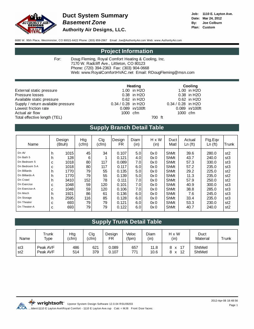
2012-Apr-08 18:48:56Uponor System Design Software 12.0.04 RSU09203 Page 1
...ilders\1110 E Layton Ave\Royal Comfort - 1110 E Layton Ave.rup Calc = MJ8 Front Door faces:
1110 E. Layton Ave.Job:Duct System SummaryMar 24, 2012Date:
Basement Zone Joe ColburnBy:CustomPlan:
Authority Air Designs, LLC.
6680 W. 95th Place, Westminster, CO 80021-6422 Phone: (303) 859-2967 Email: [email protected] Web: www.AuthorityAir.com
Project InformationDoug Fleming, Royal Comfort Heating & Cooling, Inc.For:7170 W. Radcliff Ave., Littleton, CO 80123Phone: (720) 394-2363 Fax: (303) 904-0668Web: www.RoyalComfortHVAC.net Email: [email protected]
CoolingHeatingExternal static pressure in H2O1.00in H2O1.00Pressure losses in H2O0.38in H2O0.38Available static pressure in H2O0.62in H2O0.62Supply / return available pressure 0.34 / 0.28 in H2O0.34 / 0.28in H2OLowest friction rate in/100ft0.089in/100ft0.089Actual air flow cfm1000cfm1000Total effective length (TEL) ft700
Supply Branch Detail Table
Design Htg Clg Design Diam H x W Duct Actual Ftg.EqvName (Btuh) (cfm) (cfm) FR (in) (in) Matl Ln (ft) Ln (ft) Trunk
st2280.039.6ShMt0x05.00.10734451015hDn AV
st3240.043.7ShMt0x04.00.12116128hDn Bath 5
st3330.057.3ShMt0x07.00.089117801018cDn Bedroom 5
st3235.057.2ShMt0x06.00.117117801018cDn Bedroom 5-A
st2225.029.2ShMt0x05.00.13555791770hDn Billiards
st2235.011.3ShMt0x05.00.13955791770hDn Billiards-A
st2250.057.9ShMt0x07.00.111781523410hDn Crawl
st3300.040.9ShMt0x07.00.101120591048cDn Exercise
st3285.038.8ShMt0x07.00.106120591048cDn Exercise-A
st3245.07.6ShMt0x06.00.13661861921hDn Mech
st3235.033.4ShMt0x06.00.128851162595hDn Storage
st2230.053.3ShMt0x06.00.1217979693cDn Theater
st2240.040.7ShMt0x06.00.1227979693cDn Theater-A
Supply Trunk Detail Table
Trunk Htg Clg Design Veloc Diam H x W DuctName Type (cfm) (cfm) FR (fpm) (in) (in) Material Trunk
st3 Peak AVF 486 621 0.089 657 11.8 17x8 ShtMetlst2 Peak AVF 514 379 0.107 771 10.6 12x8 ShtMetl

2012-Apr-08 18:48:56Uponor System Design Software 12.0.04 RSU09203 Page 2
...ilders\1110 E Layton Ave\Royal Comfort - 1110 E Layton Ave.rup Calc = MJ8 Front Door faces:
Return Branch Detail Table
Grill Htg Clg TEL Design Veloc Diam H x W Stud/Joist DuctName Size (in) (cfm) (cfm) (ft) FR (fpm) (in) (in) Opening (in) Matl Trunk
rb2 20x 71617 526 271.0 0.102 670 14.0 x0 0 ShMt rt4rb16 12x 1679 234 217.0 0.128 670 8.0 x0 0 ShMt rt5rb17 12x 1189 240 312.3 0.089 440 10.0 x0 0 ShMt rt5
Return Trunk Detail Table
Trunk Htg Clg Design Veloc Diam H x W DuctName Type (cfm) (cfm) FR (fpm) (in) (in) Material Trunk
rt4 Peak AVF 716 526 0.102 586 12.1 22x8 ShtMetl rt2rt5 Peak AVF 284 474 0.089 609 10.7 14x8 ShtMetl rt2rt2 Peak AVF 1000 1000 0.089 480 14.1 25x12 ShtMetl
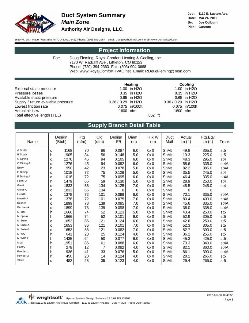
2012-Apr-08 18:48:56Uponor System Design Software 12.0.04 RSU09203 Page 3
...ilders\1110 E Layton Ave\Royal Comfort - 1110 E Layton Ave.rup Calc = MJ8 Front Door faces:
1110 E. Layton Ave.Job:Duct System SummaryMar 24, 2012Date:
Main Zone Joe ColburnBy:CustomPlan:
Authority Air Designs, LLC.
6680 W. 95th Place, Westminster, CO 80021-6422 Phone: (303) 859-2967 Email: [email protected] Web: www.AuthorityAir.com
Project InformationDoug Fleming, Royal Comfort Heating & Cooling, Inc.For:7170 W. Radcliff Ave., Littleton, CO 80123Phone: (720) 394-2363 Fax: (303) 904-0668Web: www.RoyalComfortHVAC.net Email: [email protected]
CoolingHeatingExternal static pressure in H2O1.00in H2O1.00Pressure losses in H2O0.35in H2O0.35Available static pressure in H2O0.65in H2O0.65Supply / return available pressure 0.36 / 0.29 in H2O0.36 / 0.29in H2OLowest friction rate in/100ft0.075in/100ft0.075Actual air flow cfm1600cfm1600Total effective length (TEL) ft862
Supply Branch Detail Table
Design Htg Clg Design Diam H x W Duct Actual Ftg.EqvName (Btuh) (cfm) (cfm) FR (in) (in) Matl Ln (ft) Ln (ft) Trunk
st5365.049.8ShMt0x06.00.08786701168cA Study
st5225.019.3ShMt0x05.00.14856841905hB Study
st4295.048.3ShMt0x06.00.10594451276cC Dining
st4A335.058.6ShMt0x06.00.09294451276cC Dining-A
st4A385.082.2ShMt0x05.00.0782342950hEntry
st4245.035.5ShMt0x05.00.12975721018cF Dining
st4A335.046.4ShMt0x06.00.09575721018cF Dining-A
st4250.028.9ShMt0x05.00.13059651479hFoyer-A
st4245.045.5ShMt0x07.00.125134661833cGreat
00ShMt0x000134661833cGreat-A
st4A335.070.1ShMt0x06.00.089101721378cHearth
st4A400.080.4ShMt0x07.00.075101721378cHearth-A
st4A335.045.6ShMt0x07.00.095139731899cKitchen
st4A335.036.0ShMt0x07.00.098139731899cKitchen-A
st5250.043.4ShMt0x05.00.12352741666hM Spa
st5305.052.9ShMt0x06.00.10152741666hM Spa-A
st5250.042.6ShMt0x06.00.124121861653cM Suite
st5305.052.3ShMt0x07.00.101121861653cM Suite-A
st5390.052.7ShMt0x07.00.082121861653cM Suite-B
st5255.036.2ShMt0x04.00.1242528641hM WC
st5425.045.3ShMt0x06.00.07750641435hM WIC 2
st4A340.073.3ShMt0x06.00.08861861951hMud
st4A360.082.1ShMt0x04.00.082712279hPantry
st4A390.086.1ShMt0x05.00.0763341936hPowder 1
st5265.028.1ShMt0x04.00.1241420450hPowder 2
st5265.029.4ShMt0x04.00.1233523482cStairs

2012-Apr-08 18:48:56Uponor System Design Software 12.0.04 RSU09203 Page 4
...ilders\1110 E Layton Ave\Royal Comfort - 1110 E Layton Ave.rup Calc = MJ8 Front Door faces:
Supply Trunk Detail Table
Trunk Htg Clg Design Veloc Diam H x W DuctName Type (cfm) (cfm) FR (fpm) (in) (in) Material Trunk
st5 Peak AVF 696 734 0.077 601 12.9 22x8 ShtMetlst4 Peak AVF 838 1134 0.075 544 16.1 25x12 ShtMetlst4A Peak AVF 590 772 0.075 632 13.2 22x8 ShtMetl st4
Return Branch Detail Table
Grill Htg Clg TEL Design Veloc Diam H x W Stud/Joist DuctName Size (in) (cfm) (cfm) (ft) FR (fpm) (in) (in) Opening (in) Matl Trunk
rb14 14x 1025 165 161.0 0.179 472 8.0 x0 0 ShMt rt6rb13 14x 1166 195 172.2 0.167 558 8.0 x0 0 ShMt rt6rb9 14x 20513 408 185.4 0.155 520 12.0 x0 0 ShMt rt6rb4 14x 33813 399 247.5 0.116 509 12.0 x0 0 ShMt rt7rb11 14x 1997 189 240.9 0.119 569 8.0 x0 0 ShMt rt7rb12 14x 1706 129 149.6 0.192 486 8.0 x0 0 ShMt rt7rb10 0x 1600 173 381.9 0.075 496 8.0 x0 0 ShMt rt6Arb7 0x 1500 172 222.9 0.129 492 8.0 x0 0 ShMt rt6Arb8 0x 1600 173 269.0 0.107 496 8.0 x0 0 ShMt rt6A
Return Trunk Detail Table
Trunk Htg Clg Design Veloc Diam H x W DuctName Type (cfm) (cfm) FR (fpm) (in) (in) Material Trunk
rt6 Peak AVF 893 1285 0.075 617 16.0 25x12 ShtMetl rt3rt6A Peak AVF 470 518 0.075 666 11.4 14x8 ShtMetl rt6rt3 Peak AVF 1600 2003 0.075 721 19.7 25x16 ShtMetlrt7 Peak AVF 707 717 0.116 517 12.4 20x10 ShtMetl rt3

2012-Apr-08 18:48:56Uponor System Design Software 12.0.04 RSU09203 Page 5
...ilders\1110 E Layton Ave\Royal Comfort - 1110 E Layton Ave.rup Calc = MJ8 Front Door faces:
1110 E. Layton Ave.Job:Duct System SummaryMar 24, 2012Date:
Upper Zone Joe ColburnBy:CustomPlan:
Authority Air Designs, LLC.
6680 W. 95th Place, Westminster, CO 80021-6422 Phone: (303) 859-2967 Email: [email protected] Web: www.AuthorityAir.com
Project InformationDoug Fleming, Royal Comfort Heating & Cooling, Inc.For:7170 W. Radcliff Ave., Littleton, CO 80123Phone: (720) 394-2363 Fax: (303) 904-0668Web: www.RoyalComfortHVAC.net Email: [email protected]
CoolingHeatingExternal static pressure in H2O1.00in H2O1.00Pressure losses in H2O0.35in H2O0.35Available static pressure in H2O0.65in H2O0.65Supply / return available pressure 0.50 / 0.15 in H2O0.50 / 0.15in H2OLowest friction rate in/100ft0.075in/100ft0.075Actual air flow cfm1000cfm1000Total effective length (TEL) ft867
Supply Branch Detail Table
Design Htg Clg Design Diam H x W Duct Actual Ftg.EqvName (Btuh) (cfm) (cfm) FR (in) (in) Matl Ln (ft) Ln (ft) Trunk
st1210.028.9VlFx0x06.00.20841752104hA Bath
st1395.040.6VlFx0x08.00.1141441172244cA Bedroom
st1435.024.8VlFx0x05.00.1082034958hA WIC
st1595.023.2VlFx0x04.00.0801517468hD Bath
st1535.029.3VlFx0x08.00.0881101213419hD Bedroom
st1245.018.8VlFx0x04.00.188129183cK Bath
st1290.029.1VlFx0x06.00.15592751441cK Bedroom
st1400.026.2VlFx0x07.00.11692751441cK Bedroom-A
st1630.031.6VlFx0x07.00.07557982764hLaundry
st1400.08.6VlFx0x06.00.12161641794hMezzanine
st1435.016.8VlFx0x07.00.110103971610cOpen to Great
st1500.015.4VlFx0x07.00.096103971610cOpen to Great-A
st1595.036.5VlFx0x08.00.0791491222322cUp Stairs
Supply Trunk Detail Table
Trunk Htg Clg Design Veloc Diam H x W DuctName Type (cfm) (cfm) FR (fpm) (in) (in) Material Trunk
st1 Peak AVF 1000 1000 0.075 533 16.4 19x16 DctLinr

2012-Apr-08 18:48:56Uponor System Design Software 12.0.04 RSU09203 Page 6
...ilders\1110 E Layton Ave\Royal Comfort - 1110 E Layton Ave.rup Calc = MJ8 Front Door faces:
Return Branch Detail Table
Grill Htg Clg TEL Design Veloc Diam H x W Stud/Joist DuctName Size (in) (cfm) (cfm) (ft) FR (fpm) (in) (in) Opening (in) Matl Trunk
rb5 12x 15910 197 96.8 0.159 563 8.0 x0 0 VlFx rt1rb6 12x 1387 125 90.3 0.171 515 7.0 x0 0 VlFx rt1rb3 20x 47815 473 75.6 0.204 608 12.0 x0 0 VlFx rt1rb1 0x 2260 205 205.7 0.075 414 10.0 x0 0 VlFx rt1
Return Trunk Detail Table
Trunk Htg Clg Design Veloc Diam H x W DuctName Type (cfm) (cfm) FR (fpm) (in) (in) Material Trunk
rt1 Peak AVF 1000 1000 0.075 533 16.4 19x16 DctLinr

Job #: 1110 E. Layton Ave.Performed by Joe Colburn for:
Doug Fleming7170 W. Radcliff Ave.Littleton, CO 80123
Phone: (720) 394-2363 Fax: (303) 904-0668www.RoyalComfortHVAC.net [email protected]
Authority Air Designs, LLC.
6680 W. 95th PlaceWestminster, CO 80021-6422
Phone: (303) 859-2967www.AuthorityAir.com [email protected]
Scale: 3/32" = 1'0"
Page 1Uponor System Design Software
12.0.04 RSU092032012-Apr-08 18:49:43
... Comfort - 1110 E Layton Ave.rup
N
Basement
6 "
6 "
7 "
6 "
5 "
7 "
7 "
6 "
7 "
6 "
5 "4 "
5 "
5 "
10 x 4116 cfm
4 x 10117 cfm
10 x 4117 c fm
10 x 479 cfm
10 x 486 cfm
10 x 46 c fm
10 x 479 cfm
10 x 479 cfm
4 x 12152 cfm
4 x 1045 cfm
12 x 12234 cfm
12 x 12240 cfm
10 x 479 cfm
10 "
8 "
4 "
4 x 10120 cfm
6 "
5 "
7 "
5 "
6 "
5 "
6 "
6 "
6 "
20 x 20716 c fm
14 "
25 x 1222 x 8
12 x 8 17 x 8
14 x 8
25 x 12
25 x 16
22 x 8
12 "
8 "
8 "
20 x 10
5 "
22 x 8
6 "
5 "
8 "8 "8 "
6 "
4 "
4 "
12 "25 x 12
8 "8 "
4 "
6 "
6 "
7 "
7 "
4 x 10120 cfm
7 "
7 "
7 "
14 x 8
925TA42060V17ACNPVP2417A113ANA018‐B
355CAV060080CNPVP4821A127ANA036
Master Zone
Zone
Main
SEE NOTESATTACHED INSEPERATE FILE

Job #: 1110 E. Layton Ave.Performed by Joe Colburn for:
Doug Fleming7170 W. Radcliff Ave.Littleton, CO 80123
Phone: (720) 394-2363 Fax: (303) 904-0668www.RoyalComfortHVAC.net [email protected]
Authority Air Designs, LLC.
6680 W. 95th PlaceWestminster, CO 80021-6422
Phone: (303) 859-2967www.AuthorityAir.com [email protected]
Scale: 3/32" = 1'0"
Page 2Uponor System Design Software
12.0.04 RSU092032012-Apr-08 18:49:43
... Comfort - 1110 E Layton Ave.rup
N
Main Floor
10 x 4121 cfm
10 x 4121 cfm
4 x 10121 cfm
4 x 1064 cfm
10 x 474 cfm
10 x 474 cfm
2 x 1028 cfm
10 x 220 cfm
2 x 1035 cfm
10 x 484 cfm
10 x 486 cfm
10 x 475 cfm
10 x 475 cfm
10 x 494 c fm
12 x 4134 c fm
10 x 494 cfm
10 x 4101 cfm
10 x 4101 cfm
10 x 212 c fm
10 x 241 cfm
10 x 242 cfm
10 x 486 cfm
12 x 4139 cfm
12 x 4139 cfm
14 x 6172 cfm
14 x 6173 cfm
10 x 465 cfm
12 x 4134 cfm
14 x 14408 cfm
14 x 14399 cfm
14 x 6199 cfm
14 x 6165 cfm
14 x 6195 cfm
14 x 6173 cfm
14 x 6170 cfm

Job #: 1110 E. Layton Ave.Performed by Joe Colburn for:
Doug Fleming7170 W. Radcliff Ave.Littleton, CO 80123
Phone: (720) 394-2363 Fax: (303) 904-0668www.RoyalComfortHVAC.net [email protected]
Authority Air Designs, LLC.
6680 W. 95th PlaceWestminster, CO 80021-6422
Phone: (303) 859-2967www.AuthorityAir.com [email protected]
Scale: 3/32" = 1'0"
Page 3Uponor System Design Software
12.0.04 RSU092032012-Apr-08 18:49:43
... Comfort - 1110 E Layton Ave.rup
N
Upper Floor
14 x 4149 cfm
4 x 1098 cfm
10 x 4121 cfm
10 x 464 c fm
10 x 4103 cfm
10 x 4103 cfm
10 x 434 cfm
4 x 12144 cfm
10 x 475 cfm
10 x 492 cfm
10 x 492 cfm
10 x 417 cfm
10 x 412 c fm
19 x 16
4 "
6 "
7 "
7 "
6 "
6 "
8 "
14 x 14226 cfm
12 x 1219 7 c fm
20 x 20478 c fm
12 x 12138 cfm
19 x 16
10 "
12 "
7 "
8 "
7 "
8 "
4 "7 "
8 "
5 "
925TA42060V17ACNPHP3017A113ANA024

Job #: 1110 E. Layton Ave.Performed by Joe Colburn for:
Doug Fleming7170 W. Radcliff Ave.Littleton, CO 80123
Phone: (720) 394-2363 Fax: (303) 904-0668www.RoyalComfortHVAC.net [email protected]
Authority Air Designs, LLC.
6680 W. 95th PlaceWestminster, CO 80021-6422
Phone: (303) 859-2967www.AuthorityAir.com [email protected]
Scale: 1/8" = 1'0"Page 1
Uponor System Design Software12.0.04 RSU09203
2012-Apr-08 18:47:45... Comfort - 1110 E Layton Ave.rup
NBasement
6 "
6 "
7 "
6 "
5 "
7 "
7 "
6 "
7 "
6 "
5 "4 "
5 "
5 "
10 x 4116 cfm
4 x 10117 cfm
10 x 4117 cfm
10 x 479 cfm
10 x 486 cfm
10 x 46 cfm
10 x 479 cfm
10 x 479 cfm
4 x 12152 cfm
4 x 1045 cfm
12 x 12234 cfm
12 x 12240 cfm
10 x 479 cfm
10 "
8 "
4 "
4 x 10120 cfm
6 "
5 "
7 "
5 "
6 "
5 "
6 "
6 "
6 "
20 x 20716 cfm
14 "
25 x 1222 x 8
12 x 8 17 x 8
14 x 8
25 x 12
25 x 16
22 x 8
12 "
8 "
8 "
20 x 10
5 "
22 x 8
6 "
5 "
8 "8 "8 "
6 "
4 "
4 "
12 "25 x 12
8 "8 "
4 "
6 "
6 "
7 "
7 "
4 x 10120 cfm
7 "
7 "
7 "
14 x 8
925TA42060V17ACNPVP2417A113ANA018‐B
355CAV060080CNPVP4821A127ANA036
Master Zone
Z
one
M
ain
SEE NOTESATTACHED INSEPERATE FILE
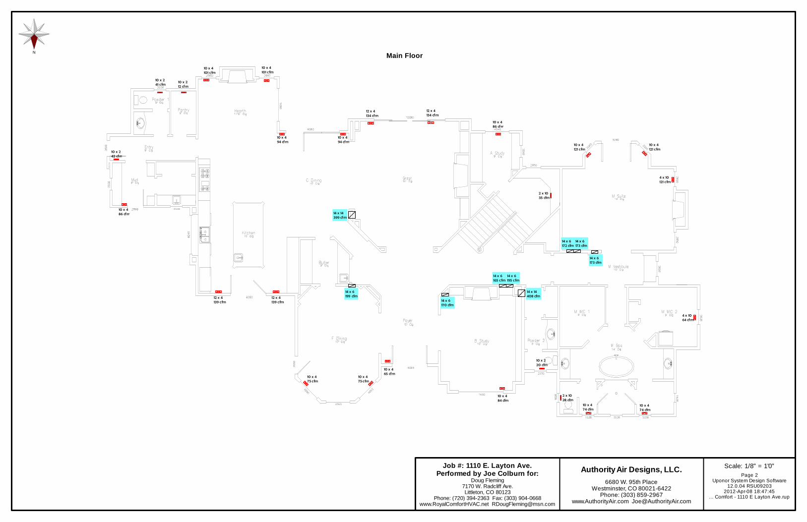
Job #: 1110 E. Layton Ave.Performed by Joe Colburn for:
Doug Fleming7170 W. Radcliff Ave.Littleton, CO 80123
Phone: (720) 394-2363 Fax: (303) 904-0668www.RoyalComfortHVAC.net [email protected]
Authority Air Designs, LLC.
6680 W. 95th PlaceWestminster, CO 80021-6422
Phone: (303) 859-2967www.AuthorityAir.com [email protected]
Scale: 1/8" = 1'0"Page 2
Uponor System Design Software12.0.04 RSU09203
2012-Apr-08 18:47:45... Comfort - 1110 E Layton Ave.rup
NMain Floor
10 x 4121 c fm
10 x 4121 c fm
4 x 10121 c fm
4 x 1064 cfm
10 x 474 cfm
10 x 474 cfm
2 x 1028 cfm
10 x 220 cfm
2 x 1035 cfm
10 x 484 cfm
10 x 486 cfm
10 x 475 cfm
10 x 475 cfm
10 x 494 cfm
12 x 4134 cfm
10 x 494 cfm
10 x 4101 c fm
10 x 4101 c fm
10 x 212 cfm
10 x 241 c fm
10 x 242 cfm
10 x 486 cfm
12 x 4139 cfm
12 x 4139 cfm
14 x 6172 cfm
14 x 6173 cfm
10 x 465 cfm
12 x 4134 cfm
14 x 14408 cfm
14 x 14399 cfm
14 x 6199 cfm
14 x 6165 cfm
14 x 6195 cfm
14 x 6173 cfm
14 x 6170 cfm

Job #: 1110 E. Layton Ave.Performed by Joe Colburn for:
Doug Fleming7170 W. Radcliff Ave.Littleton, CO 80123
Phone: (720) 394-2363 Fax: (303) 904-0668www.RoyalComfortHVAC.net [email protected]
Authority Air Designs, LLC.
6680 W. 95th PlaceWestminster, CO 80021-6422
Phone: (303) 859-2967www.AuthorityAir.com [email protected]
Scale: 1/8" = 1'0"Page 3
Uponor System Design Software12.0.04 RSU09203
2012-Apr-08 18:47:45... Comfort - 1110 E Layton Ave.rup
N
Upper Floor
14 x 4149 cfm
4 x 1098 cfm
10 x 4121 c fm
10 x 464 cfm
10 x 4103 cfm
10 x 4103 cfm
10 x 434 cfm
4 x 12144 cfm
10 x 475 cfm
10 x 492 cfm
10 x 492 cfm
10 x 417 cfm
10 x 412 cfm
19 x 16
4 "
6 "
7 "
7 "
6 "
6 "
8 "
14 x 14226 cfm
12 x 12197 cfm
20 x 20478 cfm
12 x 12138 cfm
19 x 16
10 "
12 "
7 "
8 "
7 "
8 "
4 "7 "
8 "
5 "
925TA42060V17ACNPHP3017A113ANA024

Job #: 1110 E. Layton Ave.Performed by Joe Colburn for :
Doug Flem ing7170 W. Radcl i ff Av e.L i ttleton , CO 80123
Phone: (720) 394-2363 Fax: (303) 904-0668www.RoyalCom fortHVAC.net RDougFlem ing@m sn.com
Authority Air Designs, LLC.
6680 W. 95th PlaceWestminster, CO 80021-6422
Phone: (303) 859-2967www.AuthorityAir.com [email protected]
Scale: 3/8" = 1'0"Page 1
Uponor System Design Software12.0.04 RSU09203
2012-Apr-08 18:46:24... Com fort - 1110 E Layton Av e.rup
N
Basement
6 "
6 "
7 "
6 "
5 "
7 "
7 "
6 "
7 "
6 "
5 "4 "
5 "
5 "
10 x 4116 cfm
4 x 10117 cfm
10 x 4117 cfm
10 x 479 cfm
10 x 486 cfm
10 x 46 cfm
10 x 479 cfm
10 x 479 cfm
4 x 12152 cfm
4 x 1045 cfm
12 x 12234 cfm
12 x 12240 cfm
10 x 479 cfm
10 "
8 "
4 "
4 x 10120 cfm
6 "
5 "
7 "
5 "
6 "
5 "
6 "
6 "
6 "
20 x 20716 cfm
14 "
25 x 1222 x 8
12 x 8 17 x 8
14 x 8
25 x 12
25 x 16
22 x 8
12 "
8 "
8 "
20 x 10
5 "
22 x 8
6 "
5 "
8 "8 "8 "
6 "
4 "
4 "
12 "25 x 12
8 "8 "
4 "
6 "
6 "
7 "
7 "
4 x 10120 cfm
7 "
7 "
7 "
14 x 8
925TA42060V17ACNPVP2417A113ANA018‐B
355CAV060080CNPVP4821A127ANA036
Master Zone
Zone
Main
SEE NOTESATTACHED INSEPERATE FILE

Job #: 1110 E. Layton Ave.Performed by Joe Colburn for :
Doug Flem ing7170 W. Radcl i ff Av e.Li ttle ton , CO 80123
Phone: (720) 394-2363 Fax: (303) 904-0668www.Roya lCom fortHVAC.net RDougFlem ing@m sn.com
Authority Air Designs, LLC.
6680 W. 95th PlaceWestminster, CO 80021-6422
Phone: (303) 859-2967www.AuthorityAir.com [email protected]
Scale: 3/8" = 1'0"Page 2
Uponor System Design Software12.0 .04 RSU09203
2012-Apr-08 18:46 :24... Com fort - 1110 E Layton Av e.rup
N
Main Floor
10 x 4121 c fm
10 x 4121 c fm
4 x 10121 c fm
4 x 1064 cfm
10 x 474 cfm
10 x 474 cfm
2 x 1028 cfm
10 x 220 cfm
2 x 1035 cfm
10 x 484 cfm
10 x 486 cfm
10 x 475 cfm
10 x 475 cfm
10 x 494 cfm
12 x 4134 cfm
10 x 494 cfm
10 x 4101 c fm
10 x 4101 c fm
10 x 212 cfm
10 x 241 cfm
10 x 242 cfm
10 x 486 cfm
12 x 4139 cfm
12 x 4139 cfm
14 x 6172 cfm
14 x 6173 cfm
10 x 465 cfm
12 x 4134 cfm
14 x 14408 cfm
14 x 14399 cfm
14 x 6199 cfm
14 x 6165 cfm
14 x 6195 cfm
14 x 6173 cfm
14 x 6170 cfm

Job #: 1110 E. Layton Ave.Performed by Joe Colburn for:
Doug Flem ing7170 W. Radcl i ff Av e.Li ttle ton, CO 80123
Phone: (720) 394-2363 Fax: (303) 904-0668www.Roya lCom fortHVAC.net RDougFlem ing@m sn.com
Authority Air Designs, LLC.
6680 W. 95th PlaceWestminster, CO 80021-6422
Phone: (303) 859-2967www.AuthorityAir.com [email protected]
Scale: 3/8" = 1'0"Page 3
Uponor System Design Software12.0 .04 RSU09203
2012-Apr-08 18 :46 :25... Com fort - 1110 E Layton Av e.rup
N
Upper Floor
14 x 4149 cfm
4 x 1098 cfm
10 x 4121 c fm
10 x 464 cfm
10 x 4103 cfm
10 x 4103 cfm
10 x 434 cfm
4 x 12144 cfm
10 x 475 cfm
10 x 492 cfm
10 x 492 cfm
10 x 417 cfm
10 x 412 cfm
19 x 16
4 "
6 "
7 "
7 "
6 "
6 "
8 "
14 x 14226 cfm
12 x 12197 cfm
20 x 20478 cfm
12 x 12138 cfm
19 x 16
10 "
12 "
7 "
8 "
7 "
8 "
4 "7 "
8 "
5 "
925TA42060V17ACNPHP3017A113ANA024

Calculations approved by ACCA to meet all requirements of Manual J 8th Ed.
2012-Mar-25 17:42:04Uponor System Design Software 12.0.04 RSU09203 Page 1
...110 E Layton Ave\Royal Comfort - E 1110 Layton Ave - Guest.rup Calc = MJ8 Front Door faces:
1110 E. Layton Ave. - Gu...Job:Project Summary Mar 25, 2012Date:Entire House Joe ColburnBy:
Guest SuitePlan:Authority Air Designs, LLC.
6680 W. 95th Place, Westminster, CO 80021-6422 Phone: (303) 859-2967 Email: [email protected] Web: www.AuthorityAir.com
Project Information
Doug Fleming, Royal Comfort Heating & Cooling, Inc.For:7170 W. Radcliff Ave., Littleton, CO 80123Phone: (720) 394-2363 Fax: (303) 904-0668Web: www.RoyalComfortHVAC.net Email: [email protected] SuiteNotes:
Design Information
Denver Stapleton Intl AP, CO, USWeather:
Winter Design Conditions Summer Design Conditions
Outside db °F1 Outside db °F91Inside db °F70 Inside db °F75Design TD °F69 Design TD °F16
Daily range HRelative humidity %50Moisture difference gr/lb-34
Heating Summary Sensible Cooling Equipment Load Sizing
Structure Btuh10186 Structure Btuh4991Ducts Btuh3454 Ducts Btuh2662Central vent (25 cfm) 1576 Btuh Central vent (25 cfm) Btuh361Humidification Btuh2369 Blower Btuh0Piping Btuh0Equipment load Btuh17585 Use manufacturer's data n
Rate/swing multiplier 0.96Infiltration Equipment sensible load Btuh7677
Method Latent Cooling Equipment Load SizingSimplifiedConstruction quality Tight
1 (Tight)Fireplaces Structure Btuh118Ducts Btuh-22
CoolingHeating Central vent (25 cfm) Btuh-480680680Area (ft²) Equipment latent load Btuh0
63356335Volume (ft³)Air changes/hour 0.140.27 Equipment total load Btuh7677Equiv. AVF (cfm) 1529 Req. total capacity at 0.85 SHR ton0.8
Heating Equipment Summary Cooling Equipment Summary
Make Bryant Make BryantTrade BRYANT Trade Legacy 13 SEERModel 986TA30040V14A Cond 113ANC018-BAHRI ref no.4706932 Coil CNPHP2417A
AHRI ref no.3040616Efficiency 96.5 AFUE Efficiency 11.2 EER, 13.2 SEERHeating input Btuh35776 Sensible cooling Btuh15300Heating output Btuh34882 Latent cooling Btuh2700Temperature rise °F48 Total cooling Btuh18000Actual air flow cfm800 Actual air flow cfm800Air flow factor cfm/Btuh0.059 Air flow factor cfm/Btuh0.105Static pressure in H2O0.70 Static pressure in H2O0.70Space thermostat Load sensible heat ratio 1.00

2012-Mar-25 17:42:04Uponor System Design Software 12.0.04 RSU09203 Page 1
...110 E Layton Ave\Royal Comfort - E 1110 Layton Ave - Guest.rup Calc = MJ8 Front Door faces:
1110 E. Layton Ave. - Gu...Job:AED Assessment Mar 25, 2012Date:
Entire House Joe ColburnBy:Guest SuitePlan:
Authority Air Designs, LLC.
6680 W. 95th Place, Westminster, CO 80021-6422 Phone: (303) 859-2967 Email: [email protected] Web: www.AuthorityAir.com
Project InformationDoug Fleming, Royal Comfort Heating & Cooling, Inc.For:7170 W. Radcliff Ave., Littleton, CO 80123Phone: (720) 394-2363 Fax: (303) 904-0668Web: www.RoyalComfortHVAC.net Email: [email protected]
Design ConditionsLocation: CoolingHeatingIndoor:
7570Indoor temperature (°F)Denver Stapleton Intl AP, CO, US1669Design TD (°F)ft5285Elevation:5050Relative humidity (%)°N40Latitude:
Outdoor: -34.061.1Moisture difference (gr/lb)CoolingHeatingInfiltration:911Dry bulb (°F)
)H(27-Daily range (°F)60-Wet bulb (°F)7.515.0Wind speed (mph)
Test for Adequate Exposure Diversity
Hourly Glazing Load
Hourly Average AED limit
Gla
zing
load
(B
tuh)
Hour of Day
0
200
400
600
800
1,000
1,200
1,400
1,600
8 9 10 11 12 13 14 15 16 17 18 19 20
Maximum hourly glazing load exceeds average by 21.5%.
House has adequate exposure diversity (AED), based on AED limit of 30%.
AED excursion: 0 Btuh
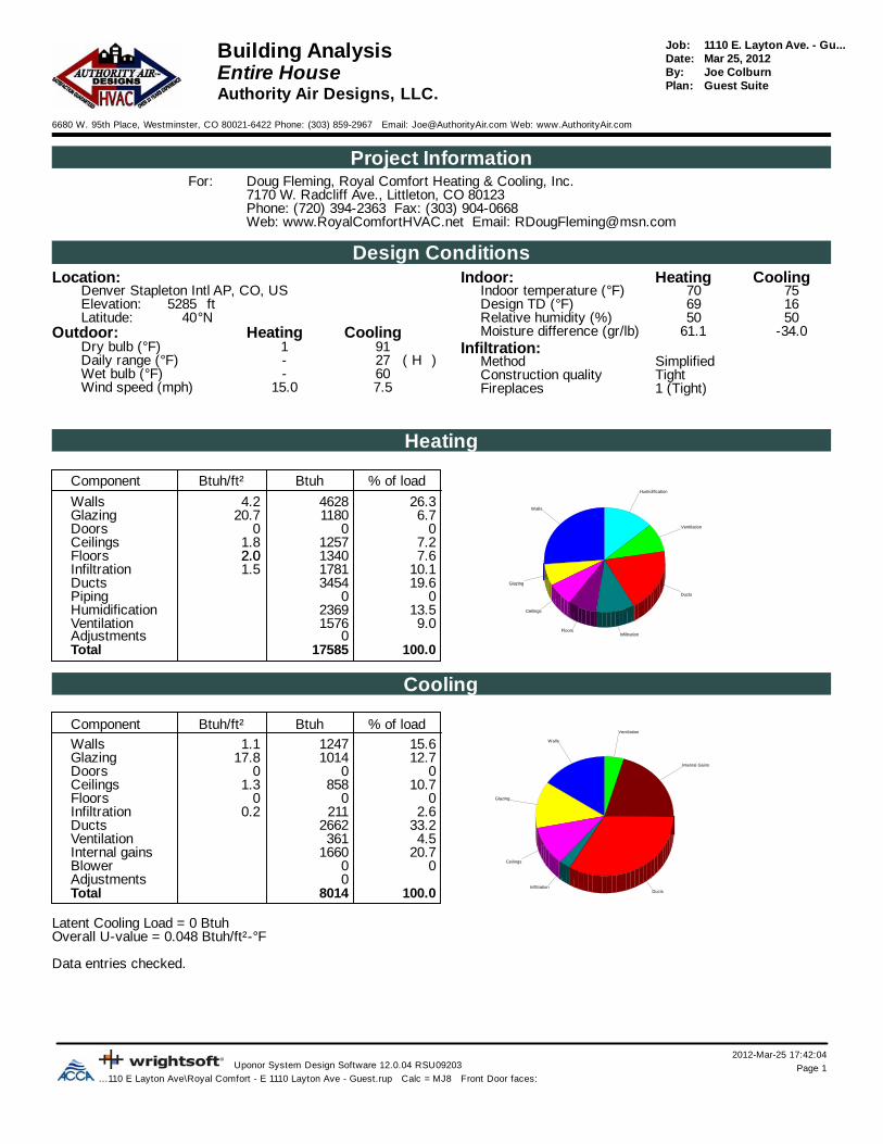
2012-Mar-25 17:42:04Uponor System Design Software 12.0.04 RSU09203 Page 1
...110 E Layton Ave\Royal Comfort - E 1110 Layton Ave - Guest.rup Calc = MJ8 Front Door faces:
1110 E. Layton Ave. - Gu...Job:Building Analysis Mar 25, 2012Date:
Entire House Joe ColburnBy:Guest SuitePlan:
Authority Air Designs, LLC.
6680 W. 95th Place, Westminster, CO 80021-6422 Phone: (303) 859-2967 Email: [email protected] Web: www.AuthorityAir.com
Project InformationDoug Fleming, Royal Comfort Heating & Cooling, Inc.For:7170 W. Radcliff Ave., Littleton, CO 80123Phone: (720) 394-2363 Fax: (303) 904-0668Web: www.RoyalComfortHVAC.net Email: [email protected]
Design ConditionsLocation: CoolingHeatingIndoor:
7570Indoor temperature (°F)Denver Stapleton Intl AP, CO, US1669Design TD (°F)ft5285Elevation:5050Relative humidity (%)°N40Latitude:
Outdoor: -34.061.1Moisture difference (gr/lb)CoolingHeatingInfiltration:911Dry bulb (°F)
SimplifiedMethod)H(27-Daily range (°F)TightConstruction quality60-Wet bulb (°F)1 (Tight)Fireplaces7.515.0Wind speed (mph)
Heating
Walls
Glazing
Ceilings
FloorsInfiltration
Ducts
Ventilation
Humidification
% of loadBtuhBtuh/ft²Component
26.346284.2Walls6.7118020.7Glazing
000Doors7.212571.8Ceilings7.613402.02.0Floors
10.117811.5Infiltration19.63454Ducts
00Piping13.52369Humidification9.01576Ventilation
0Adjustments100.017585Total
Cooling
Walls
Glazing
Ceilings
InfiltrationDucts
Internal Gains
Ventilation% of loadBtuhBtuh/ft²Component
15.612471.1Walls12.7101417.8Glazing
000Doors10.78581.3Ceilings
000Floors2.62110.2Infiltration
33.22662Ducts4.5361Ventilation
20.71660Internal gains00Blower
0Adjustments100.08014Total
Latent Cooling Load = 0 BtuhOverall U-value = 0.048 Btuh/ft²-°F
Data entries checked.

2012-Mar-25 17:42:04Uponor System Design Software 12.0.04 RSU09203 Page 1
...110 E Layton Ave\Royal Comfort - E 1110 Layton Ave - Guest.rup Calc = MJ8 Front Door faces:
1110 E. Layton Ave. - Gu...Job:Component Constructions Mar 25, 2012Date:Entire House Joe ColburnBy:
Guest SuitePlan:Authority Air Designs, LLC.
6680 W. 95th Place, Westminster, CO 80021-6422 Phone: (303) 859-2967 Email: [email protected] Web: www.AuthorityAir.com
Project InformationDoug Fleming, Royal Comfort Heating & Cooling, Inc.For:7170 W. Radcliff Ave., Littleton, CO 80123Phone: (720) 394-2363 Fax: (303) 904-0668Web: www.RoyalComfortHVAC.net Email: [email protected]
Design ConditionsLocation: CoolingHeatingIndoor:
7570Indoor temperature (°F)Denver Stapleton Intl AP, CO, US1669Design TD (°F)ft5285Elevation:5050Relative humidity (%)°N40Latitude:
Outdoor: -34.061.1Moisture difference (gr/lb)CoolingHeatingInfiltration:911Dry bulb (°F)
SimplifiedMethod)H(27-Daily range (°F)TightConstruction quality60-Wet bulb (°F)1 (Tight)Fireplaces7.515.0Wind speed (mph)
Construction descriptions GainLoss Clg HTMHtg HTMInsul RU-valueAreaOrBtuhBtuh/ft²BtuhBtuh/ft²ft²-°F/BtuhBtuh/ft²-°Fft²
WallsSTD - Frame - R-21 - Stucco: Wood Framed Wall, Stucco Exterior, 1/2" Sheathing, R-21 Cavity Insulation, 1/2" Gypsum Board
3731.1413824.2221.00.061328n2291.148514.2221.00.061202e3881.1414394.2221.00.061341s2581.149564.2221.00.061226w
12471.1446284.2221.00.0611097all
Partitions(none)
WindowsU-30 SHGC-27: U-30 SHGC-27 - Windows; NFRC rated (SHGC=0.27)
20.700.30025n 2499.9751854430.237320.700.30018e22115.829020.700.30014s
101417.8118020.700.30057all
Doors(none)
CeilingsSTD - Attic CLG - R-38: Attic Ceiling, Asphalt Shingles, R-38 Ceiling Insulation, 1/2" Gypsum Board
8581.2612571.8538.00.027680
FloorsSTD Floor - R-38: Framed Floor Over Outside Air, R-38 Cavity Insulation, Wood Floor
0013401.9738.00.029680

Calculations approved by ACCA to meet all requirements of Manual J 8th Ed.2012-Mar-25 17:42:04
Uponor System Design Software 12.0.04 RSU09203 Page 1...110 E Layton Ave\Royal Comfort - E 1110 Layton Ave - Guest.rup Calc = MJ8 Front Door faces:
1110 E. Layton Ave. - GuestJob:Right-J® WorksheetMar 25, 2012Date:Entire HouseJoe ColburnBy:Guest SuitePlan:Authority Air Designs, LLC.
6680 W. 95th Place, Westminster, CO 80021-6422 Phone: (303) 859-2967 Email: [email protected] Web: www.AuthorityAir.com
1 Room name Entire House G Bedroom2 Exposed wall 124.0 ft 42.1 ft3 Room height 9.3 dft 9.0 heat/coolft4 Room dimensions ft15.1x13.85 Room area 680.5 ft² 207.4 ft²
Ty Construction U-value Or HTM Area (ft²) Load Area (ft²) Loadnumber (Btuh/ft²-°F)(Btuh/ft²-°F) (Btuh/ft²)(Btuh/ft²) or perimeter (ft) (Btuh) or perimeter (ft) (Btuh)
Heat Cool Gross N/P/S Heat Cool Gross N/P/S Heat Cool
6 WW STD - Frame - R-21 - 0.061STD - Frame - R-21 - 0.061 nn 4.224.22 1.141.14 353 328 1382 373 119 119 503 136. GG U-30 SHGC-27U-30 SHGC-27 0.3000.300 nn 20.7020.70 9.979.97 25 0 518 249 0 0 0 0. WW STD - Frame - R-21 - 0.061STD - Frame - R-21 - 0.061 ee 4.224.22 1.141.14 220 202 851 229 136 118 497 134. GG U-30 SHGC-27U-30 SHGC-27 0.3000.300 ee 20.7020.70 30.2330.23 18 0 373 544 18 0 373 544
11 WW STD - Frame - R-21 - 0.061STD - Frame - R-21 - 0.061 ss 4.224.22 1.141.14 355 341 1439 388 124 124 522 141GG U-30 SHGC-27U-30 SHGC-27 0.3000.300 ss 20.7020.70 15.7615.76 14 0 290 221 0 0 0 0
WW STD - Frame - R-21 - 0.061STD - Frame - R-21 - 0.061 ww 4.224.22 1.141.14 226 226 956 258 0 0 0 0CC STD - Attic CLG - R- 0.027STD - Attic CLG - R- 0.027 -- 1.851.85 1.261.26 680 680 1257 858 207 207 383 262FF STD Floor - R-38STD Floor - R-38 0.0290.029 -- 1.971.97 0.000.00 680 680 1340 0 207 207 408 0
6 c) AED excursion 0 32
Envelope loss/gain 8405 3120 2687 1248
12 a) Infiltration 1781 211 585 69b) Room ventilation 0 0 0 0
13 Internal gains: Occupants @ 230230 2 460 2 460Appliances/other 1200 0
Subtotal (lines 6 to 13) 10186 4991 3271 1778
Less external loadLess external load 0 0 0 0Less transferLess transfer 0 0 0 0RedistributionRedistribution 0 0 0 0
14 Subtotal 10186 4991 3271 177815 Duct loads 34% 53% 3454 2662 34% 53% 1109 948
Total room load 13640 7653 4381 2726Air required (cfm)Air required (cfm) 800 800 257 285

Calculations approved by ACCA to meet all requirements of Manual J 8th Ed.2012-Mar-25 17:42:04
Uponor System Design Software 12.0.04 RSU09203 Page 2...110 E Layton Ave\Royal Comfort - E 1110 Layton Ave - Guest.rup Calc = MJ8 Front Door faces:
1110 E. Layton Ave. - GuestJob:Right-J® WorksheetMar 25, 2012Date:Entire HouseJoe ColburnBy:Guest SuitePlan:Authority Air Designs, LLC.
6680 W. 95th Place, Westminster, CO 80021-6422 Phone: (303) 859-2967 Email: [email protected] Web: www.AuthorityAir.com
1 Room name G Living G Bath2 Exposed wall 75.2 ft 6.8 ft3 Room height 9.5 heat/coolft 9.0 heat/coolft4 Room dimensions ft421.4x1.0 ft9.8x5.35 Room area 421.4 ft² 51.6 ft²
Ty Construction U-value Or HTM Area (ft²) Load Area (ft²) Loadnumber (Btuh/ft²-°F)(Btuh/ft²-°F) (Btuh/ft²)(Btuh/ft²) or perimeter (ft) (Btuh) or perimeter (ft) (Btuh)
Heat Cool Gross N/P/S Heat Cool Gross N/P/S Heat Cool
6 WW STD - Frame - R-21 - 0.061STD - Frame - R-21 - 0.061 nn 4.224.22 1.141.14 186 161 680 183 47 47 199 54. GG U-30 SHGC-27U-30 SHGC-27 0.3000.300 nn 20.7020.70 9.979.97 25 0 518 249 0 0 0 0. WW STD - Frame - R-21 - 0.061STD - Frame - R-21 - 0.061 ee 4.224.22 1.141.14 84 84 354 95 0 0 0 0. GG U-30 SHGC-27U-30 SHGC-27 0.3000.300 ee 20.7020.70 30.2330.23 0 0 0 0 0 0 0 0
11 WW STD - Frame - R-21 - 0.061STD - Frame - R-21 - 0.061 ss 4.224.22 1.141.14 231 217 916 247 0 0 0 0GG U-30 SHGC-27U-30 SHGC-27 0.3000.300 ss 20.7020.70 15.7615.76 14 0 290 221 0 0 0 0
WW STD - Frame - R-21 - 0.061STD - Frame - R-21 - 0.061 ww 4.224.22 1.141.14 213 213 899 242 14 14 57 15CC STD - Attic CLG - R- 0.027STD - Attic CLG - R- 0.027 -- 1.851.85 1.261.26 421 421 779 532 52 52 95 65FF STD Floor - R-38STD Floor - R-38 0.0290.029 -- 1.971.97 0.000.00 421 421 830 0 52 52 102 0
6 c) AED excursion -29 -4
Envelope loss/gain 5265 1741 453 131
12 a) Infiltration 1103 131 94 11b) Room ventilation 0 0 0 0
13 Internal gains: Occupants @ 230230 0 0 0 0Appliances/other 1200 0
Subtotal (lines 6 to 13) 6367 3072 547 142
Less external loadLess external load 0 0 0 0Less transferLess transfer 0 0 0 0RedistributionRedistribution 0 0 0 0
14 Subtotal 6367 3072 547 14215 Duct loads 34% 53% 2159 1638 34% 53% 186 76
Total room load 8526 4710 733 217Air required (cfm)Air required (cfm) 500 492 43 23

Calculations approved by ACCA to meet all requirements of Manual J 8th Ed.
2012-Mar-25 17:42:04Uponor System Design Software 12.0.04 RSU09203 Page 1
...110 E Layton Ave\Royal Comfort - E 1110 Layton Ave - Guest.rup Calc = MJ8 Front Door faces:
1110 E. Layton Ave. - Gu...Job:Load Short FormMar 25, 2012Date:
Entire House Joe ColburnBy:Guest SuitePlan:
Authority Air Designs, LLC.
6680 W. 95th Place, Westminster, CO 80021-6422 Phone: (303) 859-2967 Email: [email protected] Web: www.AuthorityAir.com
Project InformationDoug Fleming, Royal Comfort Heating & Cooling, Inc.For:7170 W. Radcliff Ave., Littleton, CO 80123Phone: (720) 394-2363 Fax: (303) 904-0668Web: www.RoyalComfortHVAC.net Email: [email protected]
Design InformationInfiltrationClgHtg
SimplifiedMethod911Outside db (°F)TightConstruction quality7570Inside db (°F)
1 (Tight)Fireplaces1669Design TD (°F)H-Daily range
5050Inside humidity (%)-3461Moisture difference (gr/lb)
HEATING EQUIPMENT COOLING EQUIPMENT
Make Bryant Make BryantTrade BRYANT Trade Legacy 13 SEERModel 986TA30040V14A Cond 113ANC018-BAHRI ref no.4706932 Coil CNPHP2417A
AHRI ref no.3040616Efficiency 96.5 AFUE Efficiency 11.2 EER, 13.2 SEERHeating input Btuh35776 Sensible cooling Btuh15300Heating output Btuh34882 Latent cooling Btuh2700Temperature rise °F48 Total cooling Btuh18000Actual air flow cfm800 Actual air flow cfm800Air flow factor cfm/Btuh0.059 Air flow factor cfm/Btuh0.105Static pressure in H2O0.70 Static pressure in H2O0.70Space thermostat Load sensible heat ratio 1.00
ROOM NAME Area Htg load Clg load Htg AVF Clg AVF(ft²) (Btuh) (Btuh) (cfm) (cfm)
G Bedroom 207 4381 2726 257 285G Living 421 8526 4710 500 492G Bath 52 733 217 43 23
Entire House d 680 13640 7653 800 800Other equip loads 3945 361Equip. @ 0.96 RSM 7677Latent cooling 0
TOTALS 680 17585 7677 800 800
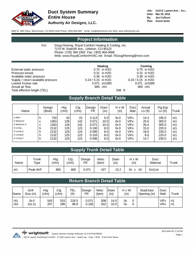
2012-Mar-25 17:42:04Uponor System Design Software 12.0.04 RSU09203 Page 1
...110 E Layton Ave\Royal Comfort - E 1110 Layton Ave - Guest.rup Calc = MJ8 Front Door faces:
1110 E. Layton Ave. - Gu...Job:Duct System SummaryMar 25, 2012Date:
Entire House Joe ColburnBy:Guest SuitePlan:
Authority Air Designs, LLC.
6680 W. 95th Place, Westminster, CO 80021-6422 Phone: (303) 859-2967 Email: [email protected] Web: www.AuthorityAir.com
Project InformationDoug Fleming, Royal Comfort Heating & Cooling, Inc.For:7170 W. Radcliff Ave., Littleton, CO 80123Phone: (720) 394-2363 Fax: (303) 904-0668Web: www.RoyalComfortHVAC.net Email: [email protected]
CoolingHeatingExternal static pressure in H2O0.70in H2O0.70Pressure losses in H2O0.31in H2O0.31Available static pressure in H2O0.39in H2O0.39Supply / return available pressure 0.24 / 0.15 in H2O0.24 / 0.15in H2OLowest friction rate in/100ft0.071in/100ft0.071Actual air flow cfm800cfm800Total effective length (TEL) ft548
Supply Branch Detail Table
Design Htg Clg Design Diam H x W Duct Actual Ftg.EqvName (Btuh) (cfm) (cfm) FR (in) (in) Matl Ln (ft) Ln (ft) Trunk
st1195.014.4VlFx0x05.00.1132343733hG Bath
st1305.025.6VlFx0x010.00.0711421281363cG Bedroom
st1305.026.4VlFx0x010.00.0711421281363cG Bedroom-A
st1220.015.0VlFx0x08.00.1001231252132hG Living
st1230.018.6VlFx0x08.00.0951231252132hG Living-A
st1220.08.6VlFx0x08.00.1031231252132hG Living-B
st1230.014.7VlFx0x08.00.0961231252132hG Living-C
Supply Trunk Detail Table
Trunk Htg Clg Design Veloc Diam H x W DuctName Type (cfm) (cfm) FR (fpm) (in) (in) Material Trunk
st1 Peak AVF 800 800 0.071 427 15.2 19x16 DctLinr
Return Branch Detail Table
Grill Htg Clg TEL Design Veloc Diam H x W Stud/Joist DuctName Size (in) (cfm) (cfm) (ft) FR (fpm) (in) (in) Opening (in) Matl Trunk
rb1 0x 5430 515 216.5 0.071 508 14.0 x0 0 VlFx rt1rb3 12x 25711 285 98.8 0.156 522 10.0 x0 0 VlFx rt1

2012-Mar-25 17:42:04Uponor System Design Software 12.0.04 RSU09203 Page 2
...110 E Layton Ave\Royal Comfort - E 1110 Layton Ave - Guest.rup Calc = MJ8 Front Door faces:
Return Trunk Detail Table
Trunk Htg Clg Design Veloc Diam H x W DuctName Type (cfm) (cfm) FR (fpm) (in) (in) Material Trunk
rt1 Peak AVF 800 800 0.071 427 15.3 19x16 DctLinr

Job #: 1110 E. Layton Ave. - GuestPerformed by Joe Colburn for:
Doug Fleming7170 W. Radcliff Ave.Littleton, CO 80123
Phone: (720) 394-2363 Fax: (303) 904-0668www.RoyalComfortHVAC.net [email protected]
Authority Air Designs, LLC.
6680 W. 95th PlaceWestminster, CO 80021-6422
Phone: (303) 859-2967www.AuthorityAir.com [email protected]
Scale: 1/8" = 1'0"Page 1
Uponor System Design Software12.0.04 RSU09203
2012-Mar-25 17:42:20... - E 1110 Layton Ave - Guest.rup
N
Guest
10 x 4125 cfm
10 x 4125 cfm
10 x 4125 cfm
10 x 4125 cfm
4 x 12142 cfm
4 x 12142 cfm
4 x 1043 cfm
12 x 12285 cfm
14 x 14543 cfm
19 x 16
14 "
10 "
8 "
8 "
10 "
10 "
8 "
8 "
19 x 16
5 "
986TA30040V14ACNPHP2417A113ANC018‐B

Job #: 1110 E. Layton Ave. - GuestPerformed by Joe Colburn for:
Doug Fleming7170 W. Radcliff Ave.Littleton, CO 80123
Phone: (720) 394-2363 Fax: (303) 904-0668www.RoyalComfortHVAC.net [email protected]
Authority Air Designs, LLC.6680 W. 95th Place
Westminster, CO 80021-6422Phone: (303) 859-2967
www.AuthorityAir.com [email protected]
Scale: 1/4" = 1'0"Page 1
Uponor System Design Software12.0.04 RSU09203
2012-Mar-25 17:43:37... - E 1110 Layton Ave - Guest.rup
N
Guest
10 x 4125 cfm
10 x 4125 cfm
10 x 4125 cfm
10 x 4125 cfm
4 x 12142 cfm
4 x 12142 cfm
4 x 1043 cfm
12 x 12285 cfm
14 x 14543 cfm
19 x 16
14 "
10 "
8 "
8 "
10 "
10 "
8 "
8 "
19 x 16
5 "
986TA30040V14ACNPHP2417A113ANC018‐B

TABLE OF CONTENTSPage
SAFETY CONSIDERATIONS...................................................1INSTALLATION CONSIDERATIONS....................................1INTRODUCTION ........................................................................1INSTALLATION ......................................................................1-4• Check Equipment And Job Site ..............................................1-2• Component Location And Wiring Considerations .....................2• Install Components ......................................................................2• Install Zone Dampers...............................................................2-3• Install Barometric Bypass Damper..........................................3-4• Install Leaving Air Temperature (LAT) Sensor.........................4• Install Heat Pump Temperature (HPT) Sensor ..........................4SYSTEM WIRING ...................................................................4-5• Wire Thermostats ........................................................................4• Wire Equipment...........................................................................4• Wire Dampers..............................................................................4• Wire Remainder .......................................................................4-5UNDERSTANDING SYSTEM OPERATION ......................5-7SYSTEM SETUP ....................................................................7-10
NOTE: Read the entire instruction manual before starting theinstallation.
SAFETY CONSIDERATIONSImproper installation, adjustment, alteration, service, maintenance,or use can cause fire, electrical shock, or other conditions whichmay cause personal injury or property damage. Consult a qualifiedinstaller, service agency or your distributor or branch for informa-tion or assistance. The qualified installer or agency must usefactory-authorized kits or accessories when modifying this prod-uct. Refer to the individual instructions packaged with the kits oraccessories when installing.
Follow all safety codes and wear safety glasses. Have fireextinguisher available. Read these instructions thoroughly andfollow all warnings or cautions attached to the unit. Consult localand state building codes and Sheet Metal and Air ConditioningNational Association (SMACNA) for special installation require-ments.
Recognize safety information. This is the safety-alert symbol .When you see this symbol on the unit or in instructions andmanuals, be alert to the potential for personal injury.
Understand the signal words DANGER, WARNING, and CAU-TION. These words are used with the safety-alert symbol. DAN-GER identifies the most serious hazards which will result in severepersonal injury or death. WARNING signifies hazards whichcould result in personal injury or death. CAUTION is used toidentify unsafe practices which would result in minor personalinjury or product and property damage. NOTE is used to highlightsuggestions which may result in ehanced installation, reliability, oroperation.
INSTALLATION CONSIDERATIONSBefore the actual installation of a zoning system can begin,decisions need to be made to determine the number and location ofzones. This affects duct and damper selections.
This instruction covers the physical installation and start up of theBryant 3-Zone system. Use this instruction to guide the actualinstallation process after all the air side decisions have been made.
1. Install in non-condensing areas with ambients between32°F and 158°F.
2. A TXV is required on the indoor coil when used with allresidential split system equipment.
3. A separate transformer is not needed to power the 3-Zonesystem. Up to five dampers may be used in each zone byelectrically connecting them in parallel.
4. Load calculations must be performed for each zone’s peakdemand. Size each zone duct for at least its peak demandplus 25%. Size equipment for the building block load, notthe sum of zone peak demands. It is important that theequipment not be oversized.
5. When only two zone operation is needed, any two of thethree zone connections may be used. There is no inherentpriority dependent on zone number.
CAUTION: UNIT DAMAGE HAZARDFailure to follow this caution may result in unit damage.TXV on indoor coil is required with all residential splitsystem equipment.
INTRODUCTIONThe Bryant 3-Zone system allows the air conditioning and heatingequipment to control temperatures in 3 distinct spaces or zoneswithin a building. Each zone has independent temperature settingscontrolled by a conventional thermostat.There are two distinct controllers:• ZONEBB3ZAC01 - Single Stage Heat / Single Stage Cool
using conventional single stage thermostats.• ZONEBB3ZHP01 - Three Stage Heat / Two Stage Cool
compatible for HP and multi-stage application thermostats andequipment.
Each system controller is comprised of a three-zone controller anda duct temperature sensor.NOTE: Thermostats are purchased separately.The comfort temperature settings can change automaticallythrough the use of schedules if programmable thermostats areselected. This allows the Bryant 3-Zone to change the temperaturesettings in zones to reflect occupancy or usage. The Bryant 3-Zonesystem uses motorized air volume control dampers (also calledzone dampers) to regulate the flow of conditioned air into thezones.
INSTALLATIONI. CHECK EQUIPMENT AND JOB SITE
A. Inspect Equipment
File claim with shipping company, prior to installation, if shipmentis damaged or incomplete.
Installationand Operating Instructions3-ZONE CONTROLZONEBB3Z(AC/HP)01
Cancels: NEW II ZONEKIT.0.1311-04
—1—
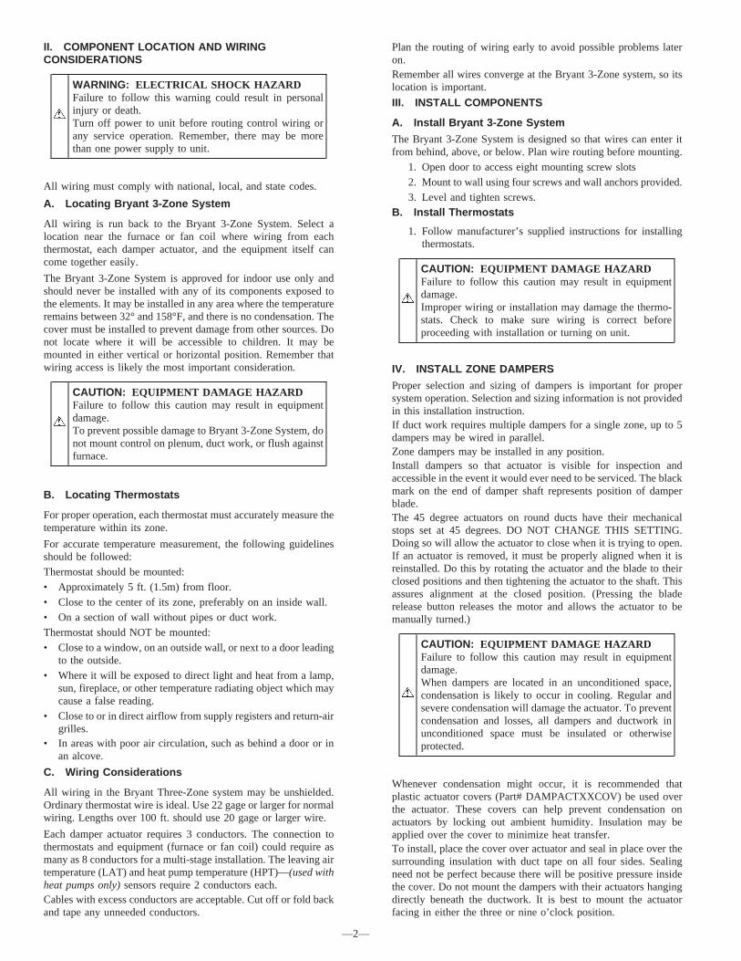
II. COMPONENT LOCATION AND WIRINGCONSIDERATIONS
WARNING: ELECTRICAL SHOCK HAZARDFailure to follow this warning could result in personalinjury or death.Turn off power to unit before routing control wiring orany service operation. Remember, there may be morethan one power supply to unit.
All wiring must comply with national, local, and state codes.
A. Locating Bryant 3-Zone System
All wiring is run back to the Bryant 3-Zone System. Select alocation near the furnace or fan coil where wiring from eachthermostat, each damper actuator, and the equipment itself cancome together easily.
The Bryant 3-Zone System is approved for indoor use only andshould never be installed with any of its components exposed tothe elements. It may be installed in any area where the temperatureremains between 32° and 158°F, and there is no condensation. Thecover must be installed to prevent damage from other sources. Donot locate where it will be accessible to children. It may bemounted in either vertical or horizontal position. Remember thatwiring access is likely the most important consideration.
CAUTION: EQUIPMENT DAMAGE HAZARDFailure to follow this caution may result in equipmentdamage.To prevent possible damage to Bryant 3-Zone System, donot mount control on plenum, duct work, or flush againstfurnace.
B. Locating Thermostats
For proper operation, each thermostat must accurately measure thetemperature within its zone.
For accurate temperature measurement, the following guidelinesshould be followed:Thermostat should be mounted:• Approximately 5 ft. (1.5m) from floor.• Close to the center of its zone, preferably on an inside wall.• On a section of wall without pipes or duct work.Thermostat should NOT be mounted:• Close to a window, on an outside wall, or next to a door leading
to the outside.• Where it will be exposed to direct light and heat from a lamp,
sun, fireplace, or other temperature radiating object which maycause a false reading.
• Close to or in direct airflow from supply registers and return-airgrilles.
• In areas with poor air circulation, such as behind a door or inan alcove.
C. Wiring Considerations
All wiring in the Bryant Three-Zone system may be unshielded.Ordinary thermostat wire is ideal. Use 22 gage or larger for normalwiring. Lengths over 100 ft. should use 20 gage or larger wire.
Each damper actuator requires 3 conductors. The connection tothermostats and equipment (furnace or fan coil) could require asmany as 8 conductors for a multi-stage installation. The leaving airtemperature (LAT) and heat pump temperature (HPT)—(used withheat pumps only) sensors require 2 conductors each.Cables with excess conductors are acceptable. Cut off or fold backand tape any unneeded conductors.
Plan the routing of wiring early to avoid possible problems lateron.Remember all wires converge at the Bryant 3-Zone system, so itslocation is important.
III. INSTALL COMPONENTS
A. Install Bryant 3-Zone System
The Bryant 3-Zone System is designed so that wires can enter itfrom behind, above, or below. Plan wire routing before mounting.
1. Open door to access eight mounting screw slots2. Mount to wall using four screws and wall anchors provided.3. Level and tighten screws.
B. Install Thermostats
1. Follow manufacturer’s supplied instructions for installingthermostats.
CAUTION: EQUIPMENT DAMAGE HAZARDFailure to follow this caution may result in equipmentdamage.Improper wiring or installation may damage the thermo-stats. Check to make sure wiring is correct beforeproceeding with installation or turning on unit.
IV. INSTALL ZONE DAMPERS
Proper selection and sizing of dampers is important for propersystem operation. Selection and sizing information is not providedin this installation instruction.If duct work requires multiple dampers for a single zone, up to 5dampers may be wired in parallel.Zone dampers may be installed in any position.Install dampers so that actuator is visible for inspection andaccessible in the event it would ever need to be serviced. The blackmark on the end of damper shaft represents position of damperblade.The 45 degree actuators on round ducts have their mechanicalstops set at 45 degrees. DO NOT CHANGE THIS SETTING.Doing so will allow the actuator to close when it is trying to open.If an actuator is removed, it must be properly aligned when it isreinstalled. Do this by rotating the actuator and the blade to theirclosed positions and then tightening the actuator to the shaft. Thisassures alignment at the closed position. (Pressing the bladerelease button releases the motor and allows the actuator to bemanually turned.)
CAUTION: EQUIPMENT DAMAGE HAZARDFailure to follow this caution may result in equipmentdamage.When dampers are located in an unconditioned space,condensation is likely to occur in cooling. Regular andsevere condensation will damage the actuator. To preventcondensation and losses, all dampers and ductwork inunconditioned space must be insulated or otherwiseprotected.
Whenever condensation might occur, it is recommended thatplastic actuator covers (Part# DAMPACTXXCOV) be used overthe actuator. These covers can help prevent condensation onactuators by locking out ambient humidity. Insulation may beapplied over the cover to minimize heat transfer.To install, place the cover over actuator and seal in place over thesurrounding insulation with duct tape on all four sides. Sealingneed not be perfect because there will be positive pressure insidethe cover. Do not mount the dampers with their actuators hangingdirectly beneath the ductwork. It is best to mount the actuatorfacing in either the three or nine o’clock position.
—2—
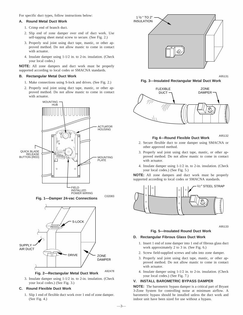
For specific duct types, follow instructions below:
A. Round Metal Duct Work
1. Crimp end of branch duct.
2. Slip end of zone damper over end of duct work. Useself-tapping sheet metal screw to secure. (See Fig. 2.)
3. Properly seal joint using duct tape, mastic, or other ap-proved method. Do not allow mastic to come in contactwith actuator.
4. Insulate damper using 1-1/2 in. to 2-in. insulation. (Checkyour local codes.)
NOTE: All zone dampers and duct work must be properlysupported according to local codes or SMACNA standards.
B. Rectangular Metal Duct Work
1. Make connections using S-lock and drives. (See Fig. 2.)
2. Properly seal joint using duct tape, mastic, or other ap-proved method. Do not allow mastic to come in contactwith actuator.
3. Insulate damper using 1-1/2 in. to 2-in. insulation. (Checkyour local codes.) (See Fig. 3.)
C. Round Flexible Duct Work
1. Slip 1 end of flexible duct work over 1 end of zone damper.(See Fig. 4.)
2. Secure flexible duct to zone damper using SMACNA orother approved method.
3. Properly seal joint using duct tape, mastic, or other ap-proved method. Do not allow mastic to come in contactwith actuator.
4. Insulate damper using 1-1/2 in. to 2-in. insulation. (Checkyour local codes.) (See Fig. 5.)
NOTE: All zone dampers and duct work must be properlysupported according to local codes or SMACNA standards.
D. Rectangular Fibrous Glass Duct Work
1. Insert 1 end of zone damper into 1 end of fibrous glass ductwork approximately 2 to 3 in. (See Fig. 6.)
2. Screw field-supplied screws and tabs into zone damper.
3. Properly seal joint using duct tape, mastic, or other ap-proved method. Do not allow mastic to come in contactwith actuator.
4. Insulate damper using 1-1/2 in. to 2-in. insulation. (Checkyour local codes.) (See Fig. 7.)
V. INSTALL BAROMETRIC BYPASS DAMPER
NOTE: The barometric bypass damper is a critical part of Bryant3-Zone System for controlling noise at minimum airflow. Abarometric bypass should be installed unless the duct work andindoor unit have been sized for use without a bypass.
Fig. 1—Damper 24-vac ConnectionsC02083
OPN COM CLS
MOUNTINGHUB
ACTUATORHOUSING
MOUNTINGPLATE
FIELDINSTALLEDPOWER WIRING
QUICK BLADERELEASE
BUTTON (RED)
Fig. 2—Rectangular Metal Duct WorkA92478
DRIVE ZONEDAMPER
S-LOCK
SUPPLYAIR DUCT
Fig. 3—Insulated Rectangular Metal Duct WorkA95131
1 / " TO 2"INSULATION
1 2
Fig 4—Round Flexible Duct WorkA95132
FLEXIBLEDUCT
ZONEDAMPER
Fig. 5—Insulated Round Duct WorkA95133
/ ″ STEEL STRAP1 2
—3—

The bypass should be installed according to local codes andSMACNA standards. Be sure bypass is properly supported.For proper installation, refer to Installation Instructions packagedwith barometric bypass.
VI. INSTALL LEAVING AIR TEMPERATURE (LAT) SEN-SOR
NOTE: The supplied LAT sensor must be installed for normaloperation. Heat pump systems may use an optional HPT (heatpump temperature) sensor for added protection. These sensorsprotect the equipment when leaving air temperatures approachexcessive levels.Locate LAT sensor in main supply trunk after heating and coolingcoil and before bypass damper and first branch. The LAT sensor isradiant shielded to prevent heat from affecting correct air tempera-ture.
1. Drill a 1/4-in. hole at location in supply trunk where sensorwill be installed.
2. Insert sensor in hole and use as a template to mark the 2mounting holes.
3. Drill two 1/16-in. holes to accept No. 6 screws throughpre-drilled holes in duct temperature sensor back plate.
4. Use 2 No. 6 sheet metal screws to mount duct temperaturesensor to unit.
5. Connect sensor to 2-conductor wire using provided wirenuts. (See Fig. 9, 10, or 11 for connection to Bryant 3-ZoneSystem.)
VII. INSTALL HEAT PUMP TEMPERATURE (HPT) SEN-SOR
The optional HPT sensor is recommended in all heat pump/fan coilinstallations. If an optional HPT sensor is not used, the 10K ohmresistor attached to the two HPT terminals on the board must beleft in place. The HPT sensor measures the temperature of the airleaving the indoor coil. The sensor is to be installed downstream ofthe indoor coil but before the electric heaters. It can be installedthrough the wall of the fan coil or may be located entirely insidethe fan coil near the blower inlet. Anchor firmly in place with cableties so that it cannot interfere with the blower wheel.
SYSTEM WIRINGWiring the system is best done in four steps. Thermostats,Equipment, Dampers, and Remainder. The descriptions below andTable 1 will help you choose the correct wiring diagram for your
system. Table 1 also shows the proper setting of dipswitches 9 and10 for each diagram. Based on the equipment, 3-zone control, andthermostat type, select the appropriate wiring diagram. Terminaldesignations on all the thermostats are those of Bryant thermostats.Other brands may vary somewhat. Wiring diagrams and 3-ZoneControl board layouts are located at the end of this InstallationInstruction.
Fig. 8 - Shows the board layout for the AC Control.Fig. 9 - Shows the board layout for the HP/2S Control.Fig. 10 - Shows the 3-Zone AC Control wiring. It supports only 1stage cooling and 1 stage heating.Fig. 11 - Shows that the 3-Zone HP/2S Control may be used in 1stage cooling and 1 or 2 stage heating applications. For 2 stageheating, the stat may be a 2 stage heat AC stat or a HP statconverted to AC. (Bryant HP stats can be field converted to 2 stageheat AC stats.)Fig. 12 - Shows the conventional HP system, using a HP stat. Onlysingle stage auxiliary heat is supported for heat pump systems.Using the HP stat allows control of emergency heat directly fromthe stat.Fig. 13 - Is also a HP system, but uses an AC stat with 2 stageheating instead of a HP stat. (Bryant HP stats can be fieldconverted to 2 stage heat AC stats.) Here, emergency heat can onlybe selected by a switch on the 3-Zone Control.Fig. 14 - Is a 2 speed AC system and may have 1 or 2 stages ofheat. An HP/2S Control and a 2S stat set for AC operation must beused.Fig. 15 - Is for a 2 speed HP. It requires an HP/2S Control and a2S stat set for HP operation. Only single stage auxiliary heat issupported for heat pump systems.I. WIRE THERMOSTATS
All zone thermostats are wired identically, so only the Zone 1thermostat is shown on the wiring diagrams. For physical locationof connections on 3-Zone Control refer to Fig. 8 (AC Control) or9 (HP Control).Battery or power stealing thermostats may not require the Cconnection. Refer to thermostat Installation Instructions. Be care-ful not to cross zone numbers.II. WIRE EQUIPMENT
Again, from the selected Fig. 10 through 15, make each connectionas shown at the indoor and outdoor units and the 3-zone Control.Connect the equipment R to both Rz and either Rh or Rc. A jumperwill be needed. Rc and Rh are internally connected but may beseparated by breaking a twist-off (see step 4 below).III. WIRE DAMPERS
Each damper has three connections: Close, Open, and Common.Find the connection points along the lower left side of the 3-ZoneControl. Suggested colors are Close = red; Open = green; Common= white. Field label and make the connections at the dampers andat the 3-Zone Control. Be careful not to cross zone numbers.IV. WIRE REMAINDER
Connect the LAT sensor to the LAT and LATC terminals. Polaritydoes not matter. If used, connect the HPT sensor to the HPT andHPTC terminals. If the HPT sensor is not used, you must leave the10K ohm resistor connected in its place.
Fig. 6—Rectangular Fibrous Glass Duct WorkA92480
ZONEDAMPER
2″ TO 3″
FIBROUSGLASSDUCTWORK
FIELDSUPPLIEDSCREWS
Fig. 7—Insulated Rectangular Fibrous GlassDuct Work
A95134
1 / ″ TO 2″INSULATION
1 2
TABLE 1—WIRING DIAGRAM SELECTION CHARTWIRING
DIAGRAM EQUIPMENT 3-ZONETYPE
STATTYPE SWITCH 9 SWITCH 10
Fig. 10 1-spd. AC,1-Stg. heat AC AC not present not present
Fig. 11 1-spd. AC,1 or 2-stg. heat HP/2S AC ON ON
Fig. 12 1-spd. HP,1-stg. aux heat HP/2S HP OFF OFF
Fig. 13 1-spd. HP,1-stg. aux heat HP/2S AC (2 ht) OFF ON
Fig. 14 2-spd. AC,1 or 2-stg. heat HP/2S 2S (AC) ON ON
Fig. 15 2-spd. HP,1-stg. aux heat HP/2S 2S (HP) OFF OFF
—4—

If the cooling and heating systems have separate transformers,twist off the Rc/Rh jumper using a pair of long nosed pliers. Thenconnect the R of the cooling transformer to Rc, the R of the heatingtransformer to Rh and the common of both transformers to C.Connect a jumper wire between Rz and Rc. Rc powers G, Y, andO outputs. Rh powers W outputs.
UNDERSTANDING SYSTEM OPERATION(READ BEFORE STARTING SYSTEM)
Mode and Damper PositionsThe thermostats determine the system heating or cooling mode.The first call in any zone sets the mode to satisfy that call. It willremain in that mode until all calls in that mode are satisfied and theequipment has been off for the time set by the auto changeovertime dipswitches. (See Timers section.)
In normal heating or cooling, the damper of any zone with a callin the current mode will be open and all other zones will be closed.When there is no call, any zone with its fan set to ON will be open,and any zone with its fan set to AUTO will be closed. If any zonefan is set to ON, the blower will be energized.
If all fan settings are AUTO, the dampers will remain in their lastposition before the equipment turned off and the blower will beoff. (This normally means one damper open and all others closed.)
When dampers are to move, all opening is done first, followed byall closing.
StagesIn multi-stage systems, the equipment stage is set by the greatestthermostat call, but may be delayed by the control’s cycle and
Fig. 8—AC or 1-Stage System Wiring DiagramA04192
Rh Rc Y1 W1
G
R C Y1 W1
G
R C Y1 W1
G
R C Y1 W1
G
CLS_1 COM_1 OPN_1
CLS _ 2 COM_2 OPN _ 2
CLS _ 3 COM_3 OPN _ 3
CRz
LATCLAT
ON
1 2 3 4 5 6 7
Relay
Relay
Relay
Fuse
Triac
Triac
Triac
Triac
Triac
Triac
Power Supply
Micro
WY1 G
Damper 1
Damper 2
Damper 3
CompressorTimer Override
Status
Rc/RhTwist Of f
Zone
Zone
Zone
Dipswitches 1- 8
To 24VACPower
To Equipment
To Zone 1Damper
To Zone 2Damper
To Zone 3Damper
To LATSensor
To ZoneThermostat
To ZoneThermostat
To ZoneThermostat
Pro
gram
min
gC
onne
ctor
Fig. 9—HP or 2-Stage System Wiring DiagramA04191
Rh Rc Y1 W1
G
Y2 W2 O
R C Y1 W1
G
Y2 W2 O
R C Y1 W1
G
Y2 W2 O
R C Y1 W1
G
Y2 W2 O
CLS_1 COM_1 OPN_1
CLS 2 COM_2 OPN 2
CLS 3 COM_3 OPN 3
CR
HPTHP
LATCLAT
ON
1 2 3 4 5 6 7 1 2 3
ON
Relay
Relay
Relay
Relay
Relay
Relay
Fuse
Triac
Triac
Triac
Triac
Triac
Triac
Power Supply
Micro
WY1 G WY2 O
Damper 1
Damper 2
Damper 3
CompressorTimer Override
E-Heat
Status E-Heat
Rc/RTwist Of f
Zone
Zone
Zone
To Zone 1Thermostat
To Zone 2Thermostat
To Zone 3Thermostat
To 24VACPower
ToEquipment
To Zone 1Damper
To Zone 2Damper
To Zone 3Damper
To HPTSensor
To LATSensor
Dipswitches 1 - 12
Con
nect
orP
rogr
amm
ing
—5—

staging timers. (See timers explanation below.) The AC Controlsupports only single stage heat and cool. The HP control supportstwo stage cooling, two stage furnace heating, and three stage HPheating (lo HP, hi HP, hi HP + aux heat.)
Emergency Heat
Emergency heat (aux heat without compressor heat) can beselected for a HP system by either of two ways: First, by selectingEheat using the Eheat override switch on the HP Control, orsecond, selection of Eheat on each of the thermostats, providedthey have the Eheat function. When either of these Eheat selectionsis made, a heating demand provides a W signal without a Y signalto the equipment.
NOTE: The second Eheat method requires HP thermostats andthat they all must be set to Eheat.
Indicator LEDs
There are 7 indicator LEDs on the AC Control and an additional 3on the HP/2S Control. Their locations are shown on Fig. 8 and 9.
Each damper has its own green LED which is ON when thedamper opens due to a calling condition or partially open due to anLAT or HPT limit condition.
Each equipment output has its own LED which is on when thatoutput is energized. Y and O outputs are yellow, W outputs are redand the G output is green.
In addition, there is a status LED whose operation is describedunder the section Error Codes.
Timers
To control excessive equipment cycling or rapid staging up, thecontrol has two timers. The cycle timer prevents the same stagefrom turning on within 10 minutes of the last time it turned on.This allows a stage to turn on for as short or as long as thethermostats request, but will not allow more than six cycles perhour.
The staging timer prevents a higher stage from turning on until thenext stage below it has been on for 15 minutes. This minimizes useof electric heat with heat HP systems.There is also a timegaurd timer which will not allow the compres-sor to be turned on until it has been off for five minutes.
A changeover timer, which can be set from 0 to 30 minutes, limitsthe control’s ability to switch between heating and cooling. Theopposite mode is prevented from coming on until the first modehas been satisfied for the selected time.
Timer Override
A momentary switch is located near the bottom of the controlcircuit board. Pressing it momentarily overrides all of the systemtimers, allowing the control to immediately jump to the highestcalling stage.
Temperature Limits and Sensors
Both the AC and HP controls have a LAT (leaving air temperature)sensor which is to be placed in the downstream air path of theheating /cooling equipment. It is used in both heating and cooling
to limit LAT to a safe value. It must be connected. The system willnot operate without it. Its setting is fixed for cooling and isadjustable in four settings for heating. Selection of best setting isdiscussed under LAT Limit Selection.The HP control also has an optional HPT Sensor (heat pumptemperature) which is to be placed downstream of the coil butahead of the electric heater. This sensor measures the temperatureof the air leaving the coil during HP heating. It is not included withthe control, but may be ordered separately as part numberTSATXXSEN01-B. A 10K ohm resistor is factory installed in itsplace when the actual sensor is not used. In the HP control only,dipswitch 11 allows the installer to temporarily disable both theLAT and the HPT sensors. Disabling of these sensors is only to bedone on a temporary basis.
CAUTION: UNIT DAMAGE HAZARDFailure to follow this caution could result in unit damage.Operating equipment with sensors disabled can causepermanent damage to HVAC equipment.
BypassThe purpose of a bypass is to limit noise in the duct system whenthe dampers are excessively restricting it. When a direct bypass(outlet air fed back directly into the return) is used, bypassingdecreases entering air temperature in cooling and increases it inheating. Excessive bypassing will lead to limit trips, either throughthe LAT /HPT sensors or the equipment internal limits.Setting the BypassSetting the bypass is a balance between too much noise (bypasstrip pressure set too high) and excessive bypassing which willcause limit trips, diminishing performance. As a general rule, thebypass should remain closed as much as possible. It should neveropen when all the dampers are open and only open as much asneeded to bring noise to an acceptable level when only one damperis open. (See System Setup for details.)LAT Limit SelectionCycling on internal equipment limits is to be avoided because itoverstresses and can shorten the life of the equipment. Therefore,the LAT limit setting should be selected to trip below theequipment limit. See System Setup for details on how to chooseone of four available LAT limits.Limit Levels and ActionsThe response of the system to the LAT/HPT sensors are shown inTable 2. Cooling and HP limits are not adjustable. Looking atTable 2, there are eight limit level index numbers, 0 through 7.These represent the closeness of the actual LAT/HPT temperaturesto the final shutdown limit. 0 represents no limit challenge while7 indicates a final shutdown of the equipment. Note that progres-sive actions are taken by the control as the LAT/HPT limit isapproached. Each action progressively reduces the limit challengeby increasing airflow. Normally, the system will stabilize at limitlevel 1 or 2 because opening all closed dampers 2 or 4 positions(out of 15) will reduce LAT to a level below its limit.
TABLE 2—LIMIT TEMPERATURE LEVELS AND ACTIONS
LIMIT LEVEL 0 1 2 3 4 5 6 7Cooling Limit (40 deg) above 47 46 45 44 43 42 41 40
HP limit (115 deg) below 107 108 109 110 111 112 113 115Heat Limit (130 deg) below 119 121 122 124 125 127 128 130Heat Limit (145 deg) below 131 133 135 137 139 141 143 145Heat Limit (160 deg) below 143 145 148 150 153 155 158 160Heat Limit (175 deg) below 155 158 161 164 166 169 172 175
LIMIT ACTIONS″Closed″ Damper Positions 0 2 4 6 8 10 12 14
Allowed stages (1 stg) 1 1 1 1 1 1 1 0Allowed Stages (2 stg) 2 2 2 1 1 1 1 0Allowed stages (3 stg) 3 3 3 2 2 1 1 0
—6—

Using Limit Level Indicator
The final setting of the bypass for best performance has alwaysbeen something of a black art. The 3-Zone System has a newfeature to simplify this adjustment. While the system is operating,these limit level numbers, if greater than zero, are flashed on thestatus LED.
Once the proper LAT limit choice is made based on equipmentmaximum rise, the limit level indicator assists in setting the bypasspressure adjustment. See System Setup for details.
Installer Test Mode
Dipswitch 4 selects a special Installer Test Mode, designed toassist the installer (or service person) to commission the system. Itverifies damper movement in proper zone and that the heating andcooling equipment operates properly at each stage. When thismode is selected, by moving dipswitch 4 to ON, the followingsequence will be executed once:
Step 1 — Two minutes, one flash of status LED. The blower isenergized with G, damper 1 opens, and other dampers are closed.
Step 2 — Two minutes, two flashes of LED: With the blower on,damper 1 closes and damper 2 opens.
Step 3 — Two minutes, three flashes of LED: With the blowerON, damper 3 opens and damper 2 closes.
Step 4 — Two minutes, four flashes of LED: All dampers open,first stage of heat turns on. For HP control only, this is followed bythe second stage of heat (HP plus aux heat, hi HP, or hi furnace)for two more minutes. For HP control with two stage compressor,the third stage of heat (hi HP plus aux heat) comes on for a third2 minute period.
Step 5 — Two minutes, five flashes of LED: All dampers are openand first stage of cooling turns on for 2 minutes. For HP boardonly, second stage of cooling comes on for an additional 2minutes.
At the end of Step 5, the control returns to normal operation. Torestart the test sequence, the switch must be moved to OFF andthen back to ON.
If zoning is disabled (Switch 5 = ON), the procedure above will befollowed, except all the dampers will remain open throughout thesequence.
SYSTEM SETUPThermostats
Read the thermostat Installation Instructions and be sure tocomplete the required setup of these devices before using them tobring on the equipment. If the thermostats have a ″zoning″selection, be sure to turn it on. This will eliminate the timers withinthe thermostat and allow the 3-Zone control’s timers to do theirjob.
There are 8 dipswitch settings on the AC zone control and anadditional 4 on the HP board. Below is a table summarizing theirfunction. Below the table is a more detailed description of whateach does and how to set it properly for your application.
DipswitchesDipswitch 1- This determines whether or not a minimum timemust pass before the control is allowed to transition betweenheating and cooling or vice versa. If it is set to ON, there is no time
requirement. Default is OFF.Dipswitch 2 - This switch, together with dipswitch 3, determinesthe changeover time, effective if switch 1 is OFF. ON sets 30minutes. OFF sets 20 minutes. Default is OFF.Dipswitch 3 - This is a multiplier, modifying the time set on switch2. ON multiplies the set time by 0.5. OFF multiplies the set timeby 1.0. Default is OFF.Dipswitch 4 - This selects the Installer Test Mode, used to checksystem operation. Details are provided in section Installer Test.ON selects Installer Test. OFF selects normal operation. Default isOFF.Dipswitch 5 - Enables and disables zoning. ON disables zoning,with all dampers open and zone 1 thermostat controlling. OFFselects normal zoning operation. Default is OFF.Dipswitch 6 - Selects G ON or OFF with W. Selecting ON causesG to be energized whenever W is energized. Selecting OFF doesnot bring on G with W. Default is OFF.Dipswitch 7 and 8 - Sets LAT limit temperature. See LAT LimitSelection for proper setting. Default is OFF = 145° limit.The following dipswitches are on the HP/2S control only:Dipswitch 9 - Informs the control whether it is connected to a heatpump or an air conditioner. OFF selects HP. ON selects AC.Default is OFF.Dipswitch 10 - Informs the control of the type of thermostat beingused. OFF selects HP thermostat. ON selects AC thermostat. A HPthermostat may not be selected if the system selection is AC. A2-stage heat AC thermostat or a HP thermostat may be used witha single stage HP. Default is OFF (HP).Dipswitch 11 - Disables LAT and HPT safeties when ON. ON isintended only for emergencies. When ON is selected, there is noover/under temperature protection for the equipment. Default isOFF.Dipswitch 12 - Informs the control whether the reversing valve isenergized in cooling (O function) or heating (B function). ONselects B function. OFF selects O function. Default is OFF.
LAT Limit Selection
To accommodate varying heat rises in furnaces and fan coils, theLAT limit adjustment has four selections: 130, 145, 160 and 175degrees. In addition to these, the HPT limit is fixed at 115 degreesand the cooling limit (also sensed by LAT sensor) is 40 degrees.To select the proper limit, check or calculate the rated maximumrise of the equipment. Add 75 degrees to this value. Pick theclosest LAT limit choice below this value and use dipswitches 7and 8 to enter this value using:
TABLE 4—DIPSWITCH SETTINGS FOR HP CONTROLONLY
DIPSWITCH 2 POSITION ACTION(OFF)
ACTION(ON)
9 HP Operation AC Operation10 HP Thermostat AC Thermostat
11 LAT and HPT SafetiesEnabled
LAT and HPT SafetiesDisabled
12 Reversing Valve Ener-gized in Cooling (O)
Reversing Valve Ener-gized in Heating (B)
TABLE 3—DIPSWITCH SETTINGS
DIPSWITCH1 POSITION
ACTION(OFF)
ACTION(ON)
1 Auto changeover TimerActive
DefeatAuto Changeover
Timer
2 Auto Changeover 20Minutes
Auto Changeover30 Minutes
3 Auto ChangeoverTimer X 1
Auto ChangeoverTimer X .5
4 Normal Operation Installer Test5 Zoning Enabled Zoning Disabled6 Fan With W Disabled Fan With W Enabled7 LAT Setting LAT Setting8 LAT Setting LAT Setting
TABLE 5—LAT LIMIT
TEMPERATURE SWITCH 7 SWITCH 8130 OFF ON
145 (default) OFF OFF160 ON OFF175 ON ON
—7—
Take a minute to study the LAT Limit table. Note that the limitsare the final shutdown temperatures, but actions begin earlier.First, at levels 1 and 2, closed dampers begin to open gradually,followed at level 3 by staging down of multi stage equipment, if itexists. Under most limit challenges, the system will stabilizebetween 1 and 3 due to opening of closed dampers.
CAUTION: UNIT DAMAGE HAZARDFailure to follow this caution could result in unit damage.Setting LAT limit too high can shorten the life of theHVAC equipment.
Automatic Checkout
An automatic checkout procedure is provided which will exercisedampers, heating, and cooling in that order. It is described underthe Understanding System Operation section in Installer TestMode. This may be used or the system may be checked outmanually by creating thermostat calls. When using thermostats,remember that only the calling zoning dampers will be open. Thisprovides the means to select which dampers are open for anyheating or cooling call. It is advisable that the initial checkout bemade with all dampers open before the bypass is set. This can bedone by temporarily setting Switch 5 to ON (disable zoning) andcontrolling the equipment from the Zone 1 thermostat. When theequipment is operating satisfactorily, return Switch 5 to OFF andproceed to the next section.
Bypass Adjustment
The bypass should be set to the highest possible pressure settingconsistent with an acceptable air noise level. To set, operate thesystem with a call from the smallest zone at its highest airflow(highest may be either heating or cooling). This condition forcesthe largest amount of air through the smallest duct, creating thehighest static pressure at the bypass. Adjust the bypass pressuresetting so that the bypass stays closed. Then check to determine ifthe level of noise and ″blow″ in that zone is acceptable. If it isunacceptable, reduce the bypass pressure setting (see bypassinstructions for how to adjust) until it just begins to crack open.Check again, continuing the process until an acceptable noise and″blow″ level is reached.
If, under this condition, the LAT approaches its limit, the systemwill open the other closed dampers until the LAT reaches anacceptable level. This operation is acceptable. The system willautomatically open dampers enough to keep the LAT at a safevalue, and will do it only when the zone demands require it. Youmay observe the limit level on the status LED (if it is above zero).If it stabilizes at a value of higher than 2, an overly small ductsystem is indicated and it would be desirable to raise the bypasspressure setting, if possible.
Error Codes
The status LED indicates normal operation, problems, andLAT/HPT limit status according to a two digit code. The first digitflashes its number, followed by a 2 second pause, followed by thesecond digit, followed by a 4 second pause. The cycle the repeats.The codes are:
TABLE 6—ERROR CODES
ON CONTINUOUSLY NO PROBLEMS11 - 17 LAT limit level 1 - 721 - 27 HPT limit level 1 - 7
31 LAT shorted32 LAT open33 HPT open34 HPT shorted41 Invalid: Sw 9=ON; Sw 10=OFF
—8—

AC 3-ZONE CONTROL
ZONE 1INPUT
ZONE 1AC TSTAT
EQIUPMENT
POWER
FURNACEOR
FAN COILAIR
CONDITIONER
COOL
HEAT
FAN
R RC
Y/Y2
G
C
Y1
GW1
RcY1
GW1
Rh RC
Y
GW
RzC
C
Y
Fig. 10 — AC 3-Zone Control, AC STAT, 1-Stg. ACwith 1-Stg. Heat
A04196
HP/2S 3-ZONE CONTROL
ZONE 1INPUT
ZONE 1AC TSTAT EQIUPMENT
POWER
FURNACEOR
FAN COILAIR
CONDITIONER
COOL
(LO) HEAT
FAN
RC
Y/Y2
G
RzC
(HI HEAT)
RC
Y1
GW1
Y2
W2O
SWITCH 9=ON
SWITCH 10=ON
RC
Y1
GW1
Y2
W2O
RC
Y
G
W2
C
Y
Fig. 11 — HP/2S 3-Zone Control, AC Stat, 1-Stg. ACwith 1 or 2-Stg. Heat
A04197
H P/2S 3-ZONE CONTROL
ZONE 1INPUT
ZONE 1AC TSTAT EQIUPMENT
POWER
FAN COIL HEAT PUMP
HT AND CL
AUX HT
FAN
RC
Y/Y2
G
RzC
REV VALVE
RC
Y1
G
W1
Y2
W2O
SWITCH 9=OFF
SWITCH 10=OFF
Rh
Y1
GW1
Y2
W2O
RC
Y
G
C
Y
Rc
O O
W
R
Fig. 12 — HP/2S 3-Zone Control, HP Stat, 1-Stg. HPwith 1-Stg. Aux. Heat
A04198
—9—

H P/2S 3-ZONE CONTROL
ZONE 1INPUT
ZONE 1AC TSTAT EQIUPMENT
POWER
FAN COIL HEAT PUMP
COOL
HP HEAT
FAN
RC
Y/Y2
G
RzC
AUX HEAT
RC
Y1
G
W1
Y2
W2O
SWITCH 9=OFF
SWITCH 10=ON
Rh
Y1
GW1
Y2
W2O
RC
Y
G
C
Y
Rc
O O
W2
R
W
Fig. 13 — HP/2S 3-Zone Control, AC Stat, 1-Stg. HPwith 1-Stg. Aux. Heat
A04199
H P/2S 3-ZONE CONTROL
ZONE 1 INPUT
ZONE 12S AC TSTAT EQIUPMENT
POWER
FURNACEOR FAN
COIL
LO COOL
(LO) HEAT
FAN
RC
G
RzC
(HI HEAT)
RC
Y1
GW1
Y2
W2O
SWITCH 9=ON
SWITCH 10=ON
Rh
Y1
GW1
Y2
W2O
RC
Y1
G
C
Y1
RcR
Y/Y2HI COOL Y2
W2
Y2
2 SPEEDAIR
CONDITIONER
Fig. 14 — HP/2S 3-Zone Control, AC Stat, 2-Spd ACwith 1 or 2-Stg. Heat
A04200
H P/2S 3-ZONE CONTROL
ZONE 1INPUT
ZONE 12S AC TSTAT EQIUPMENT
POWER
FAN COIL
LO HT AND CL
AUX HT
FAN
RC
G
RzC
REV VALVE
RC
Y1
GW1
Y2
W2O
SWITCH 9=ON
SWITCH 10=ON
Rh
Y1
GW1
Y2
W2O
RC
Y1
G
C
Y1
Rc
W2
R
Y/Y2 HI HT AND CL Y2 Y2
HEAT PUMP
O O
W
Fig. 15 — HP/2S 3-Zone Control, HP Stat, 2-Spd HPwith 1-Stg. Aux. Heat
A04201
—10—

—11—

SERVICE TRAINING
Packaged Service Training programs are an excellent way to increase yourknowledge of the equipment discussed in this manual, including: • Unit Familiarization • Maintenance • Installation Overview • Operating SequenceA large selection of product, theory, and skills programs is available, using popularvideo-based formats and materials. All include video and/or slides, plus companionbook.
Classroom Service Training plus "hands-on" the products in our labs can meanincreased confidence that really pays dividends in faster troubleshooting, fewercallbacks. Course descriptions and schedules are in our catalog.
CALL FOR FREE CATALOG 1-800-644-5544
[ ] Packaged Service Training [ ] Classroom Service TrainingA94328
© 2004 Bryant Heating & Cooling Systems 7310 W. Morris St. Indianapolis, IN 46231 —12— Printed in U.S.A. iizonekit013 Catalog No. 809-60007