Embed Size (px)
Citation preview
Originally published as: Schiller, S., Tino, G., Gill, P., Salomon, C., Sterr, U., Peik, E., Nevsky, A., Görlitz, A., Svehla, D., Ferrari, G., Poli, N., Lusanna, L., Klein, H., Margolis, H., Lemonde, P., Laurent, P., Santarelli, G., Clairon, A., Ertmer, W., Rasel, E., Müller, J., Iorio, L., Lämmerzah, C., Dittus, H., Gill, E., Rothacher, M., Flechtner, F., Schreiber, U., Flambaum, V., Ni, W.-T., Liu, L., Chen, X., Chen, J., Gao, K., Cacciapuoti, L., Holzwarth, R., Heß, M. P., Schäfer, W. (2009): Einstein Gravity Explorer–a medium-class fundamental physics mission. - Experimental Astronomy, 23, 2, 573-610 DOI: 10.1007/s10686-008-9126-5
1
Einstein Gravity Explorer - A medium-class fundamental physics mission S. Schiller
Institut für Experimentalphysik, Heinrich-Heine-Universität, 40225 Düsseldorf, Germany
G. Tino
Dipartimento di Fisica and LENS – Università di Firenze, CNR/INFM, INFN - Sez. di Firenze, 50019 Sesto Fiorentino, Italy
P. Gill
National Physical Laboratory, Teddington TW11 0LW, United Kingdom
C. Salomon
Laboratoire Kastler Brossel, Ecole Normale Supérieure, 24 rue Lhomond, 75231 Paris France
U. Sterr, E. Peik
Physikalisch-Technische Bundesanstalt, Bundesallee 100,38116 Braunschweig, Germany
A. Nevsky, A. Görlitz
Institut für Experimentalphysik, Heinrich-Heine-Universität, 40225 Düsseldorf, Germany
D. Svehla
Institute of Astronomical and Physical Geodesy, Technische Universität München, Arcisstrasse 21, 80333 Munich, Germany
G. Ferrari, N. Poli
Dipartimento di Fisica and LENS - Università di Firenze, CNR/INFM, INFN - Sez. di Firenze, 50019 Sesto Fiorentino, Italy
L. Lusanna
INFN, Sez. di Firenze, Polo Scientifico, 50019 Sesto Fiorentino, Italy
H. Klein, H. Margolis
National Physical Laboratory, Teddington TW11 0LW, United Kingdom P. Laurent, G. Santarelli, P. Lemonde, A. Clairon,
LNE-SYRTE, Observatoire de Paris, 61 Avenue de l'observatoire, 75014 Paris, France
W. Ertmer, E. Rasel
Leibniz Universitaet Hannover, Institut für Quantenoptik, Welfengarten 1, 30167 Hannover, Germany
2
J. Müller
Institut Für Erdmessung, Leibniz Universität Hannover, Schneiderberg 50, 30167 Hannover, Germany
L. Iorio
V.le Unità di Italia 68, 70125 Bari, Italy
C. Lämmerzahl, H. Dittus
Centre of Applied Space Technology and Microgravity (ZARM), Universität Bremen, Am Fallturm , 28359 Bremen, Germany
E. Gill
Department of Earth Observation and Space Systems, Delft University of Technology, Kluyverweg 1, 2629 HS Delft, The Netherlands
M. Rothacher, F. Flechner
GeoForschungsZentrum, Potsdam, Germany
U. Schreiber
Fundamentalstation Wettzell, 93444 Bad Koetzting, Germany
V. Flambaum
University of New South Wales, Sydney, Australia
Wei-Tou Ni
Purple Mountain Observatory, Chinese Academy of Sciences, Nanjing, 210008, China
Liang Liu
Shanghai Institute of Optics and Fine Mechanics, Chinese Academy of Sciences Jiading, Shanghai 201800, China
Xuzong Chen, Jingbiao Chen
Institute of Quantum Electronics, School of Electronics Engineering and Computer Science, Peking University, Beijing 100871, China
Gao Kelin
Wuhan Institute of Physics and Mathematics, The Chinese Academy of Sciences P.O.Box 71010, Wuhan 430071
L. Cacciapuoti
ESA Research and Scientific Support Department, ESTEC, 2200 AG Noordwijk ZH, The Netherlands
Ronald Holzwarth
3
Max-Planck-Institut für Quantenoptik, 85748 Garching,Germany, and Menlo Systems GmbH, 82152 Martinsried, Germany
M. P. Heß
ASTRIUM Space Transportation, D-88093 Friedrichshafen, Germany
W. Schäfer
TimeTech GmbH, 70563 Stuttgart, Germany
4
Abstract: The Einstein Gravity Explorer mission (EGE) is devoted to a precise measurement of the
properties of space-time using atomic clocks. It tests one of the most fundamental predictions of
Einstein’s Theory of General Relativity, the gravitational redshift, and thereby searches for hints of
quantum effects in gravity, exploring one of the most important and challenging frontiers in
fundamental physics. The primary mission goal is the measurement of the gravitational redshift with an
accuracy up to a factor 104 higher than the best current result. The mission is based on a satellite
carrying cold atom-based clocks. The payload includes a cesium microwave clock (PHARAO), an
optical clock, a femtosecond frequency comb, as well as precise microwave transfer methods between
space and ground. The tick rates of the clocks are continuously compared with each other, and nearly
continuously with clocks on earth, during the course of the 3-year mission. The highly elliptic orbit of
the satellite is optimized for the scientific goals, providing a large variation in the gravitational potential
between perigee and apogee. Besides the fundamental physics results, as secondary goals EGE will
establish a global reference frame for the Earth’s gravitational potential and will allow a new approach
to mapping Earth’s gravity field with very high spatial resolution. The mission was proposed as a class-
M mission to ESA’s Cosmic Vision Program 2015-2025.
Keywords: gravitational redshift; gravitational frequency shift; atomic clock; optical clock;
Equivalence Principle, Local Position Invariance; Special Relativity; Lorentz Invariance;
General Relativity, geoid, frequency transfer;microwave link, gravitational potential;
5
1. Introduction
Einstein’s theory of General Relativity is a cornerstone of our current description of the physical world.
It is used to describe the motion of bodies ranging in size from satellites to galaxy clusters, the
propagation of electromagnetic waves in the presence of massive bodies, and the dynamics of the
Universe as a whole. In general, the measurement of general relativistic effects is very challenging, due
to their small size [1, 2]. Thus, only few of its predictions have been tested with high accuracy, for
example the time delay of electromagnetic waves via the Cassini mission [3], and the existence of
gravitational waves by observation of binary star systems. The accuracy of the determination of these
effects is at the 20 ppm level.
The situation is similar for one of the most fascinating effects predicted by General Relativity
and other metric theories, the slowing of clocks in a gravitational field (gravitational time dilation,
gravitational redshift). The gravitational redshift was measured with 7×10⁻⁵ inaccuracy in the 1976
Gravity Probe-A experiment [4] by comparing a ground clock with a similar clock on a rocket as the
height changed. The most performing clocks available at the time, hydrogen masers, were used for this
experiment. The ACES (Atomic Clock Ensemble in Space) mission planned to fly on the ISS in 2014
seeks to improve the determination by a factor 25, by using a cold atom clock (PHARAO) and a
hydrogen maser [5]. Recent progress on cold atom clocks in the optical domain and in optical
technology enable performing this fundamental test with orders of magnitude better sensitivity.
Although it has been very successful so far, General Relativity, as well as numerous other
alternative or more general theories proposed in the course of the development of theoretical physics,
are classical theories. As such, they are fundamentally incomplete, because they do not include quantum
effects. In fact, it has not yet been possible to develop a theory of gravity that includes quantum
mechanics in a satisfactory way, although enormous effort has been devoted to this goal. Such a theory
would represent a crucial step towards a unified theory of all fundamental forces of nature. Several
approaches have been proposed and are currently under investigation (e.g. string theory). A full
understanding of gravity will require observations or experiments that determine the relationship of
gravity with the quantum world. This topic is a prominent field of activity and includes the current
studies of dark energy.
The Einstein Gravity Explorer is a fundamental physics mission dedicated to this question; its
primary task is to measure the gravitational frequency shift with unprecedented accuracy. The EGE
mission uses a satellite on a highly elliptic orbit (see Fig. 1). The ratios of the frequencies of two on-
board clocks and the ratios between satellite and ground clocks are the main observables. These can be
interpreted toward tests of General Relativity (GR) and of competing metric theories of gravity and as
tests for the existence of new fields associated to matter (see Sec. 3). The outcome of the mission will be
either a confirmation of GR and metric theories within the accuracy provided by the instruments, or the
discovery of a deviation. In the latter case, the mission would provide a first indication of the breakdown
6
of current (classical) gravitational physics theories and could pave the way towards a unified theory of
all forces.
2. Scientific Objectives
2.1 Summary of science objectives
Fundamental physics science objectives (1 ppm = 1 part in 106, 1 ppb = 1 part in 109)
Primary Objectives
- High-precision measurement of the earth gravitational frequency shift at 25 ppb accuracy, a factor
3000 improvement
- First precise measurement of the sun gravitational frequency shift at 1 ppm level, a factor 2×10⁴
improvement
- Test of space and time variability of fundamental constants with accuracy 30 ppb
- First search for neutron scalar charge, with accuracy 30 ppb
- Test of anomalous coupling of matter to the Standard Model quantum fields
Secondary Objectives
- Tests of Lorentz Invariance in the matter and photon sector (factor 20 improvement)
- Contribution towards establishing a new definition of the unit of time
Spin-off to other fields (outside fundamental physics):
- Establishment of a new approach to the determination of the geopotential, with geoid height
resolution of a few cm
- Comparison of distant terrestrial clocks at the 10-18 level
- Demonstration of clock and link technology for future applications, e.g. in precision spacecraft
navigation
- Demonstration on high performance real-time range determination with precision 25 times (based on
code phase) to 1000 times (based on carrier phase) higher compared to systems onboard previous
missions (ERS-2, TOPEX POSEIDON)
- Comparison of 3 different orbit determination systems: Laser-Ranging, µm-precision microwave
ranging, GPS-based orbit determination
- Atmospheric signal propagation study, precise determination of 3rd order ionospheric term
- Monitoring stability of the Galileo/GPS/Glonass time scales
7
2.2 Gravitational frequency shift measurement and search for new physics
The primary science goal of EGE is a measurement and test of the gravitational frequency shift
in the weak-field limit, as predicted by metric theories of gravitation. These theories also predict that the
shift is independent of the type of clock used to measure it. The comparison of the frequencies ν of two
identical clocks 1, 2, operating at different locations x1, x2 , yields a frequency ratio
ν2(x’)/ν1(x’) ≅ 1 + (U(x2) - U(x1))/c2 . (1)
Here, νi(x’) is the frequency of clock i located at xi, as observed (measured) at a particular location x’
where the comparisons are performed. The comparison location can be arbitrary but will often be x1, or
x2, or both. U is the gravitational potential, U(x) = - GM/|x|, in case of a spherically symmetric body of
mass M. In short, time runs (or clocks tick) more slowly the closer the system/clock is to a massive
body. Stationary clocks and observers and weak gravitational fields have been assumed in Eq. (1).
Through its measurement, EGE searches for a possible violation of the gravitational frequency shift. A
violation may be described phenomenologically by a dependence of one or more fundamental constants
on the gravitational potential, X = X(U/c2), where X is a generic dimensionless fundamental constant or
a dimensionless combination of fundamental constants. Such a dependence is a violation of the principle
of Local Position Invariance (LPI), which states that the outcome of local, nongravitational experiments
is independent of where and when in the Universe they are performed. If a constant depends on the
gravitational potential, then the results of those laboratory-type (i.e. local) experiments that depend on
that constant, will also depend on the location, namely on the location of the laboratory with respect to
the mass distribution generating the potential, and will violate LPI.
LPI is one of the three cornerstones of the Einstein Equivalence Principle (EEP), the others
being the Weak Equivalence Principle and Local Lorentz Invariance. It is a common belief that the EEP
may not be absolutely valid - therefore spatial dependence and time dependence of fundamental
constants have become a very intense research topic in the last decade, with experiments undertaken
worldwide to search for violations of various aspects of EEP. For example, extensive studies of atomic
and molecular spectra of gas clouds in the distant Universe are currently undertaken to search for a
difference of these parameters compared to today’s values (see e.g. [6, 7] and references therein). Also,
some differences in Big Bang nucleosynthesis data and calculations can be naturally explained by a
variation of fundamental constants [8].
The EGE mission is thus a probe of possible space-dependence of fundamental constants. The
search may help to point the way toward a unified theory of all forces, reveal hypothetical extra
dimensions in our Universe or the existence of many sub-Universes with different physics, chemistry
and biology. Indeed, theories unifying all forces, applied to cosmology, suggest space and time
dependence of the coupling constants [9]. Another argument for spatial variation of fundamental
constants comes from the anthropic principle. There must be a fine tuning of fundamental constants
which allows humans and any life to appear. Life in its present form is not consistent with fundamental
8
constants whose values only slightly differ from the actual ones. This fine tuning can be naturally
explained by the spatial variation of the fundamental constants: we appeared in the area of the Universe
where the values of the fundamental constants are consistent with our existence.
In the Standard Model there are three main fundamental dimensionless parameters determining
the structure and energy levels of stable matter (atoms, molecules): the electromagnetic fine structure
constant α and the ratio of two particle masses (electron mass me and light quark mass mq) to the strong
QCD energy scale ΛQCD, Xe,q = me,q⁄ΛQCD. The fundamental masses me and mq are proportional to the
vacuum Higgs field which determines the electroweak unification scale. Therefore, the constants
me,q⁄ΛQCD can also be viewed as the ratio of the weak energy scale to the strong energy scale.
How can a space-time variation of the fundamental constants and a dependence on the
gravitational potential may occur? Light scalar fields very naturally appear in modern cosmological
models, affecting α and me,q⁄ΛQCD. One of these scalar fields is the famous “dark energy” which causes
accelerated expansion of the Universe. Another hypothetical scalar field is the dilaton, which appears in
string theories together with the graviton. Cosmological variation of these scalar fields should occur
because of drastic changes of matter composition of the Universe. During the Big Bang nucleosynthesis
the Universe was dominated by radiation, then by cold dark matter and now by dark energy. Changes of
the cosmic scalar field ϕ0(t) lead to the variation of the fundamental constants X(ϕ0). Massive bodies
(galaxies, stars, planets) can also affect physical constants. They have a large scalar charge S
proportional to the number of particles S = spZ+seZ+sn N, where Z is the number of protons and
electrons and N is the number of neutrons; sp, se, sn are the scalar charges of protons, electrons and
neutrons, respectively. There is also a contribution of the nuclear binding energy (scalar charge of
virtual mesons mediating nuclear forces).
The scalar charge produces a Coulomb-like scalar field ϕs=S/R , where R is the distance from
the charge. The total scalar field is ϕ = ϕ0+ ϕs , therefore we may have a variation of the fundamental
constants inversely proportional to the distance from massive bodies,
X (ϕ) = X(ϕ0+ ϕs)= X (ϕ0) + δ X(R) ,
δ X(R) = (d X /dϕ) S/R ,
where a nonzero δ X violates LPI and a small ϕs was assumed.
The gravitational potential U is essentially proportional to the number of baryons Z + N and inversely
proportional to the distance R, U = - GM/R . Therefore, the change of the fundamental constants near
massive bodies can be written:
δ X/X = K(X,i) δ (Ui/c2) , (2)
where i refers to a particular composition of the mass M, and where the coefficients K(X,i) = − (d X /dϕ)
Si/GMi are not universal, but are expected to be different for, e.g., the Sun and Earth, K(X, Earth) ≠ K(X,
Sun). Indeed, the Sun consists mostly of hydrogen; therefore the Sun’s scalar charge is SSun > Z(sp+se).
The Earth contains heavier elements where the number of neutrons exceeds the number of protons,
9
N=1.1 Z. Therefore, the scalar charge of the Earth SEarth > Z (1.1 sn + sp + se) and is sensitive to the
neutron scalar charge (and also to the contribution of the nuclear binding), in contrast to the sun.
The most sensitive experiments suitable for search of a space-time dependence in local or near-
local experiments (such as satellite experiments) are clock-clock comparison. In one type of terrestrial
local experiment, dissimilar clocks located nearby are compared for a duration spanning at least one
year. During such periods, the earth moves periodically closer and further away from the sun, so that the
solar gravitational potential on Earth varies. This enables a search for a dependence of the fundamental
constants on the sun’s scalar charge [10, 11]. These experiments are able to set limits to K(Sun) for α
and me,q⁄ΛQCD, at the level of 10-6 [8].
The proposed EGE satellite experiments are complementary to terrestrial experiments, allowing
to set limits to K(Earth) and, combining with the K(Sun) results from terrestrial comparisons, setting
limits on the dependence of the fundamental constants on the neutron scalar charge sn .
In summary, when the frequencies of two identical clocks (of nominal frequency νa) that are located at
different positions x1, x2, are compared by measuring their frequency ratio at some position x’, the result
may be written as
νa,2(x’)/νa,1(x’) = 1 + [ 1 + ΣX AX,a K(X,i) ]( Ui(x2)-Ui (x1) ) / c2 . (3)
The measurement of this ratio, which is sensitive to K, represents a test of General Relativity’s redshift.
The sensitivity factor AX,a = X (d(ln νa)/dX) is the sensitivity of the clock frequency to a particular
constant X, and can be calculated using atomic and nuclear theory (see e.g. [8]).
When the frequencies of two co-located but dissimilar clocks a, b (of nominal frequencies νa,0 and νb,0 )
are compared in-situ at two locations x1, x2 (LPI test), the result is
[νa,1(x1)/νb,1(x1)] / [νa,2(x2)/νb,2(x2) ] = 1 + [ΣX (AX,a – AX,b) K(X,i) ] (Ui(x2)-Ui (x1)) / c2 . (4)
The result of the EGE mission may be given as a limits for (or nonzero values of) K(X, Earth), for the
three fundamental constants X = α, me⁄ΛQCD , and mq⁄ΛQCD .
2.3 Measurement approaches for the gravitational frequency shift
The gravitational potential experienced by the ground and satellite clocks includes the contributions
from the earth and the sun (the contribution from the moon is an order smaller and may be neglected for
the purposes of the discussion, but will be taken into account in data analysis).
Nonzero gravitational frequency shift signals (Eq. (3)) can be obtained in three ways. Method (1) below
is the most sensitive, and represents a strong reason to have an optical clock, which on short averaging
times is able to provide a higher frequency stability than a microwave clock. Method (2) and (3) are less
accurate, but are complementary in terms of measurement approach. Finally, method (3) addresses the
10
solar gravitational frequency shift while (1) and (2) measure the terrestrial effect. The performance of
the instruments assumed in the following is shown in Fig. 2.
(1) Repeated measurements of satellite clock frequency variation between apogee
and perigee
In this measurement approach, the difference between earth - satellite clock frequency ratio at perigee
and apogee is considered. This difference is measured at each perigee and apogee passage, and averaged
over the mission duration. Systematic shifts (if not correlated with orbital motion) are expected to
average out, leading to a gain in sensitivity of up to n1/2, where n = number of orbits. This mode uses the
stability properties of the satellite clocks on the timescale from perigee visibility to apogee visibility,
rather than their accuracy. Assuming a specification of ≤ 3×10-16 satellite optical clock fractional
frequency instability for integration times between 1000 s and 25 000 s, n ≅ 1000 comparisons (i.e. most
orbits of the mission), and a perigee-apogee potential difference ΔU/c2 ≅ 4×10⁻¹⁰ allows a measurement
of the redshift at 25 ppb accuracy. The ground clocks to which the satellite clocks are compared to at
perigee and at apogee will be located in different ground stations. The inaccuracy of these ground clocks
must therefore be sufficiently smaller than 1×10-17 in order not to contribute to the 25 ppb error. Current
state-of-the art inaccuracy is 2×10-17 and is likely to decrease further.
(2) Absolute comparison between ground and satellite clocks with the satellite at
apogee
Here the terrestrial gravitational potential difference is maximum, ΔU/c2 ≅ 6.5.10-10. Assuming a space
optical clock inaccuracy of 1×10-16 and a ground clock inaccuracy a factor 3 lower (current state-of-the-
art), allows a measurement of the redshift at 150 ppb. This measurement takes advantage of the
repetitive nature of the orbit only to a small extent and relies on the accuracy of the optical clocks, in
particular of the space clocks. It is thus complementary to (1), albeit less accurate.
In (1) and (2), the dominant contribution to the redshift is from earth’s gravitational potential. The
contribution from the solar potential is strongly reduced due to the fact that satellite and earth are an
interacting system in free-fall toward the sun [12], and can be modeled.
(3) Comparisons between terrestrial clocks
The frequency comparison link to the EGE satellite allows terrestrial clock comparisons by a common-
view method, whereby the frequency signals from two distant ground clocks are sent to the satellite and
compared there. The frequency difference between two identical ground clocks is determined, if
systematic instrumental errors are negligible, by the difference in gravitational potential at the two clock
locations. This potential difference includes a terrestrial and a solar contribution.
The solar contribution varies according to the orientation of the clock pair with respect to the sun with a
1 day-period. For two clocks at a surface distance of ~ 6000 km and suitable orientation with respect to
11
the sun, the normalized modulation amplitude is ≅ 4×10-13. This is the same as the earth potential
difference for 4 km height difference. It is expected that ground clocks will have reached an inaccuracy
at the level of 1×10-18 at the time of the mission in 2015+. Using the microwave link, a comparison of
ground clocks over ~ 3 h (typical common-view duration) with a resolution of 1×10-17 can be performed,
limited by the instability of the link. Repeating the clock comparison at each common-view window (n
= 1000 comparisons) will allow averaging, and a measurement of the solar gravitational shift with
fractional inaccuracy of 1 ppm. In comparison, the best current results for the solar gravitational
frequency shift are at the few-percent level [13, 14]. A moderate averaging out of ground clock
systematic shifts is assumed, as well as modeling of the earth gravitational potential variations on the
daily timescale at the appropriate level.
(4) Comparisons of on-board clocks
The two on-board clocks are continuously compared; these data are analyzed for violation of LPI, Eq.
(4). Since the measurement is a null test, the required accuracy of the gravitational potential at the
satellite location is low and easily satisfied.
2.4 Test of Local Position Invariance and search for neutron scalar charge
The test of LPI is performed in conjunction with the measurement of the gravitational frequency shift.
With approach 2.1(1), the optical clock will be able to measure
K (α, Earth) with accuracy 30 ppb (spec).
Combining the results of the microwave and optical clocks will determine
K(me⁄ΛQCD,Earth) + ε K(mq⁄ΛQCD,Earth) with accuracy 85 ppb (spec), where ε ≈ - 0.1.
Simultaneously, the on-board comparison 2.1.(4) yields the combination
1.9 K(α, Earth) + K(me⁄ΛQCD,Earth) + ε K(mq⁄ΛQCD,Earth) with accuracy 85 ppb (spec).
Note that these measurements are fully complementary to current and future terrestrial clock-clock
comparisons, which are sensitive to K(X, Sun), and can be combined with those to determine or set
limits to the neutron scalar charge.
2.5 Theoretical analysis of frequency comparison signals
The on-board clock-clock comparison signals can be analyzed straightforwardly in terms of a violation
of LPI, since signal propagation effects are absent.
The determination of the gravitational frequency dilation via ground-satellite clock comparisons is more
complex (Eq.(1) is strongly simplified) and requires an accurate treatment of all relevant relativistic
effects. Gravitation in the solar system is described in the barycentric (BCRS) and geocentric (GCRS)
non-rotating celestial reference systems by means of post-newtonian solutions of Einstein's equations for
the metric tensor in harmonic gauges codified in the conventions IAU2000 [15]. In these conventions
the relativistic structure of Newton potential (order 1/c2) and gravitomagnetic (order 1/c3) potentials are
given. For the Newton potential the multipolar expansion of the geopotential determined by gravity
mapping is used. The post-Newtonian effects of the metric (described in terms of dimensionless
parameters β and γ) can be included. Orbits of satellites are evaluated in the GCRS at the level of a few
cm by means of the Einstein-Infeld-Hoffmann equations at the order 1/c2 [16] using the relativistic
Newton potential. Instead the trajectories of the ground clocks in the GCRS are evaluated from their
positions fixed on the Earth crust (ITRS, International Terrestrial Reference System) by using the non-
relativistic IERS2003 conventions [17].
For the propagation of light rays (here: radio signals) between the satellite and the ground stations one
uses the null geodesics of the post-Newtonian solution in the GCRS. The time/frequency transfer
properties have been theoretically evaluated for an axisymmetric rotating body [18, 19] at the order 1/c4
(i.e. with Newton and gravitomagnetic potentials developed in multipolar expansions). These results
have been developed for use in the ACES mission. The relative frequency dilation can be expressed as
( )4
12
1 11 n nnn
L L Gc c
νν =
Δ= + + +∑ ,
where Ln describes special-relativistic Doppler effects and Gn the general-relativistic effects. These
quantities are time-dependent due to the orbital motion. For concreteness, we report the orders of the
terms. The kinematical effects are |L1/c| < 1×10⁻⁵, |L2/c2| < 2×10⁻¹⁰, |L3/c3| < 3×10-15, |L4/c4| < 7×10-20.
The Newtonian contributions are G2 = G2(M) + G2
(J_2) + G2(J_4) + G2
(J_6) (M is the mass monopole, Jn are
the lowest multipoles), with estimates |G2(M)/c2| < 3×10-11, |G2
(J_2)/c2| < 2×10-13, |G2(J_4)/c2| < 3×10-16,
|G2(J_6) /c2| < 1×10-16. For G3 = G3
(M) + G3(J_2), the estimates are |G3
(M)/c3| < 2×10-14, |G3(J_2)/c3| < 1×10-18.
Finally, the G4 = G4(M) + G4
(S) contributions (G4(S) is the lowest gravitomagnetic effect) are of order
|G4(M)/c4| < 1×10-19, |G4
(S) /c4| < 1×10-22, and thus not relevant for EGE.
The available theory is fairly complete for the data analysis in mode 2.1(1), described below.
For modes 2.1(2, 3), the theory will need to be generalized to include the effect of the gravitational
potential at the location of the ground clock(s) (including time-varying effects, such as the tides) and of
the solar and lunar potentials.
The uncertainties of the various contributions above are minimized by a using precise EGE orbit
data obtained by satellite tracking, and by using current and future accurate earth gravity information.
Required orbit position knowledge is at 1 cm level near perigee, and ~ 50 cm near apogee, reachable
already today with the proposed orbitography approach described below. The validity of the special-
relativistic Doppler shift has been and will continue to be independently verified with increased
accuracy by spectroscopy of relativistic atomic ion beams [20]. Potential violations of this aspect of
Lorentz Invariance are expected to be sufficiently bounded so as not to affect the signal interpretation.
12
13
2.6 Local Lorentz Invariance Tests
There has been an explosion of interest in Local Lorentz Invariance in recent years [21], with numerous
astronomical studies and high-precision experiments applied to search for violations of Lorentz
Invariance. Significant developments have also occurred on the theoretical side, and a theory (standard
model extension, SME [22]) has been worked out that provides a unified framework for describing and
analyzing Lorentz Invariance violations in a variety of systems. Two aspects of Lorentz Invariance can
be tested with EGE.
2.6.1 Independence of the speed of light from the laboratory velocity
A possible dependence of the speed of light on the speed v of the laboratory can be modeled, according
to the Mansouri-Sexl test theory [23], by
c(v) = c0 (1 + B v2/c2)
Here v > v0 = 377 km/s is the velocity with respect to the cosmic microwave background, the
cosmologically preferred frame, and B is a combination of parameters describing deviations from the
usual Lorentz transformation formulas. B = 0 if Lorentz Invariance holds. For a terrestrial experiment,
the rotation of the Earth around its axis modulates v with a 300 m/s amplitude. A dependence c(v) can be
searched for by measuring the frequency difference between a highly stable optical cavity (cavity
frequencies are proportional to c) and an optical clock (Kennedy-Thorndike-type experiment [24]) and
determining the modulation of the frequency difference correlated with the modulation of v. The
advantages of a space experiment are the high orbital velocity and strongly reduced cavity deformation
thanks to microgravity [25]. On the proposed elliptic orbit, v varies between +4 km/s and −4 km/s over
approx. one hour. This variation is 13 times larger than for the case of a terrestrial experiment. The
shorter time scale is also advantageous, since the drift of the cavity is more predictable. In the EGE
mission, the reference cavity of the clock laser is used. The large number of orbits improves the
statistics. An improvement of the accuracy of B by a factor 20 compared to the best current terrestrial
results is realistic. The data analysis can also be performed in the framework of the SME theory, taking
into account complementary bounds obtained from terrestrial experiments and astrophysical
observations.
2.6.2 Independence of Zeeman splitting frequency on the direction of the magnetic
field
One class of tests of Lorentz Invariance consists in measuring the frequency splitting between two levels
of a quantum system induced by a static magnetic field, as a function of orientation of the field direction
with respect to the stars (Hughes-Drever-type experiments [21]). This class addresses the so-called
matter sector, and is complementary to combined-photon/matter-sector tests such as the above. The
most precise experiments are performed with atomic clocks, e.g. masers or cold atom clocks [26]. The
EGE instruments allow such experiments, since magnetic fields are applied continuously in the clock or
repeatedly for calibration. Compared to terrestrial experiments, the high orbital velocity of EGE is could
lead to an improvement by a factor ~ 20.
2.7 Application to geophysics
Using GPS, coordinates of a point on the Earth can be obtained with an inaccuracy well below 1 cm in a
well defined international terrestrial reference system. The coordinates are purely geometrical and do
not contain any gravity information. A local gravitational potential is determined with respect to a
reference gravitational potential by “levelling” the surface of the Earth, i.e. sequentially measuring
gravity and height differences every ca. 50 m:
BU
AU
gr
( ) ,B
B AA
U U g r d n− = − ⋅∫r r r
where is the difference vector between subsequent locations. The disadvantage of measuring
height differences by the levelling method is a random walk effect of accumulated errors.
nr
In the classical definition, a geoid is defined as the particular equipotential surface nearest to mean sea
level. In these terms, the geoid serves as a reference surface for measuring the height and also to define
a reference for the gravitational potential. Such a vertical reference frame, historically was realized for a
country or several countries by determining the mean of sea level observations at tide gauge stations
taken over long period of time. However, modern satellite altimetry missions such as Topex/Poseidon or
Envisat show that departure of the mean sea level from an equipotential surface may reach up to several
meters on the global scale, see e.g. [27]. Therefore, heights systems based on different tide gauge
stations may differ in the realisation of the geoid and may differ with respect to the reference by several
meters.
The best gravity field models obtained from satellite data (e.g. mission GRACE) have reached a
precision of about 1 cm over ~250 km half wavelength [28], Satellite data also reveals changes in time
[29] However, for typical Earth topography with height variations of e.g. 1000 m over 30 km horizontal
distance, one may expect variations in the geoid of about 80 cm. Such a high-spatial frequency signal in
geoid variations cannot be detected by space gravity missions and requires a combination of satellite and
terrestrial gravity measurements, like gravity anomalies, deflections of vertical and GPS/levelling
points. The best combined global gravity field models are provided up to degree and order 360 in terms
of spherical harmonic representation, corresponding to a half-wavelength of about 55 km. However, in
combining the satellite and terrestrial gravity field measurements the problem of terrestrial data given in
different height systems between continents and different countries remains and has to be tied to satellite
measurements.
14
15
The geodetic scientific community is currently establishing a Global Geodetic Observing
System (GGOS), [30]. Its objectives are the early detection of natural hazards, the measurement of
temporal changes of land, ice and ocean surfaces as well as the monitoring of mass transport processes
in the Earth system. Global change processes are small and therefore difficult to quantify. Therefore the
required precision, relative to the Earth’s dimension is 1 ppb. GGOS will be established by the
combination of geodetic space techniques (GPS, Laser-Ranging, VLBI) and realized by a very large
number of terrestrial and space-borne observatories. The purely geometric terrestrial 3D coordinate
system is in good shape and fully operational. It has to be complemented, however, with a globally
uniform height system of similar precision. The current precision level of regional height systems, in
terms of gravity potential differences, is in the order of 1 m2/s2 (10 cm) with inconsistencies between
these various systems up to several 10 m2/s2 (several meters). The actual requirement in the context of
GGOS is 0.1 m2/s2 (1 cm) with the need of a permanent, i.e. dynamical, control. This requirement of
high precision height control comes from the need to understand, on a global scale, processes such as
sea level change, global and coastal dynamics of ocean circulation, ice melting, glacial isostatic
adjustment and land subsidence as well the interaction of these processes. Only by means of monitoring
in terms of gravity potential changes at the above level of precision the change of ocean level can be
understood as a global phenomenon and purely geometric height changes be complemented by
information about the associated density or mass changes.
The geoid can also be defined in a relativistic way [31], as the surface where accurate clocks run
with the same rate and where the surface is nearest to mean sea level. The relation between the
differences in the clock frequencies and the gravitational potential is given in simplified form by Eq. (1).
At present there is no operational way to compare frequencies of the already available optical clocks on
the global scale at the same level as their accuracy would allow. With EGE and by then improved
ground optical clocks it will become possible to obtain gravitational potential differences on a global
scale by comparing frequencies. This would be a significant new dimension to gravity field
determination, since such observables are given on the global scale and provide in situ local gravity
information at the same time. EGE will allow clock-based gravitational potential mapping with the same
payload instruments used for the fundamental physics experiments. The on-board clocks are actually not
required for this purpose, MOLO, MWL and FCDP suffice. Thus, EGE will allow establishing a global
reference frame for the Earth gravitational field with accuracy in the order of a few cm in terms of the
geoid heights. This assumes that by the time EGE is operational, (mobile) ground clocks with fractional
inaccuracy at the level of 10-18 are available; the measurements are limited by MWL noise and thus
require a long integration times to match the expected ground clock performance. Such a reference
frame will serve as reference for all gravity field modeling and clocks will be used to define time scale
(TAI) and Earth gravitational potential at the same time.
16
In summary, with optical clocks geodesy will undergo a second revolution: after geometry now
being measured by clock-based GNSS systems, also physical heights and potential will be measured by
(mobile) optical clocks using the gravitational redshift effect.
2.8 Application to frequency standards and terrestrial fundamental physics studies As has been described, repeating ground clock comparisons and integrating over several months will
provide global ground clock frequency comparisons at the level of 1×10-18, more than two orders of
magnitude below the current GPS and two-way satellite time and frequency transfer methods. In the
time and frequency community, the availability of such a global high performance microwave link will
accelerate the process leading to a redefinition of the SI second based on clocks operating in the optical
domain.
The global character of the ground clock comparisons made possible by EGE can also contribute to the
search for a time-variation of the fundamental constants.
The comparisons do not require availability of the on-board clocks. The risk of this type of
measurements is therefore reduced. Moreover, the lifetime of many subunits required for this
measurement (MWL and FCDP, see below) can exceed 10 years (from previous experience with similar
devices) and thus offers a motivation to increase the mission duration beyond the nominal 3 years.
Further applications to metrology are listed under the secondary goals in Sec. 2.1 above.
17
3 Mission Profile
3.1 Orbit
The orbit must satisfy the following requirements:
Primary: (i) Large gravitational potential difference between apogee and perigee,
(ii) sufficient contact time to at least two ground stations at perigee
Secondary: Simultaneous visibility of satellite from distant (inter-continental) ground stations for
several hours.
To satisfy the primary objective, the orbit must be highly elliptic. The perigee should be low. A very
low perigee means a short contact time, which decreases the accuracy of the frequency measurement. A
compromise is a perigee altitude of ~ 2500 km. For a sufficiently high apogee, this yields a ΔU of 60%
of the theoretical maximum between the earth surface and infinity.
The baseline scenario is an orbit of approx. 12 h period, with the following properties:
Apogee Altitude: 37856 km (-10 deg latitude, two over Atlantic and Pacific, resp.)
Perigee Altitude: 2500 km (+ 10 deg latitude, two over Guatemala and Malaysia, resp.)
Inclination: 63.4 deg, argument of perigee: 170 deg
RAAN 25 deg, True Anomaly: 220 deg
Apogee drift rate: 70 km/d, perigee drift ~ 14 km/d
True anomaly and right ascension of the ascending node (RAAN) were optimized to minimize orbital
precession. Fig. 3 shows the ground tracks and the ground coverage at one of the perigees. Common-
view contact time for stations in Europe is about 6 h, while between a station in Europe and in the USA
it is about 3.5 h. Frequency comparison windows between a given ground station and EGE repeat every
24 h.
A final selection of the orbit requires an in-depth study of the costs of the propellant and maneuvers as
well as of the setting up of new ground stations.
3.2 Ground segment
The mission requires two separate ground segments: the science ground segment and the standard
satellite control segment which supports telemetry and telecommand (TM/TC).
3.2.1 Science ground segment
As described above, one part of the mission is to perform frequency comparisons between ground-to-
space and ground-to-ground (common-view and non-common view). The use of a 2-way microwave
link (MWL) system has the advantage that a precise orbit or the precise relative velocity of the satellite
must not be known [4]. The orbit determination requirements for a 2-way system are significantly
18
relaxed compared to the requirements to model the relativistic effects on the clocks. The frequency
comparison results are available both on ground and on the satellite.
For ground-to-satellite clock comparisons 5 ground stations are favourable, two capable of viewing
perigee, three for viewing apogee. This allows for the classic 3-clock configuration, where the
performance of each clock can be obtained individually. The perigee stations will be observing the
satellite for ~25 min every perigee passage for the duration of the mission. The apogee stations will
observe for ~ 3 h every apogee passage. Of course, a larger number of stations, as well as longer
observation time are useful for robustness, redundancy, and orbit determination.
The stations must have access to optical clocks of performance at least as high as the space
clocks. They will include an optical frequency comb, by means of which the optical clock frequency is
transformed to a radiofrequency for comparison with the EGE clocks. The stations could be installed on
a temporary basis for the duration of the mission. High-accuracy fiber-optic link technology already
existing today allows distances of ~ 100 km between the ground station and the corresponding optical
clock, allowing a certain freedom in the choice of the ground station location. With further increase of
the fiber-optic link range, currently being investigated, the area over which the ground station can be
positioned relative to the optical clock will increase. This option is of importance for the implementation
of a geophysics measurement campaign for which a large number of ground station locations is of
interest.
The above ground stations will be complemented by some 15 additional ground terminals provided by
the world-wide laboratories equipped with high performance primary clocks at the time of the mission.
These will participate in orbit determination to 1 cm accuracy along the full orbit, which can be
achieved with non-optical atomic clocks. The EGE MWL is fully compatible to planned ACES ground
terminals, which might reduce the number of required stations.
With a larger number of transportable optical clock ground stations deployed and moved across
the continents, a geophysics campaign could be implemented to map the gravitational potential.
A. Ground station equipment
MWL uses dedicated small transportable terminals, which can be easily installed at any location of
interest. Each terminal consists of a steerable dish antenna of 1 m diameter, with pointing accuracy of
0.1°, using a transmit power of 5 W per band. The high directivity antenna (Ka-band : 0.7°, Ku-band:
1.4°, S-band: 20°) avoids multi-path from nearby objects. Antenna noise temperatures are: Ka-band: 450
K, Ku-band: 340 K. Operation is at elevations above 10° and measurements are performed above 20°.
For ranging purposes, terminal location is determined by GPS surveying. Each ground station computes
its own ionospheric corrections based on a triple-band receiver. The terminal has a built-in delay
monitor, which allows calibrated ranging during several months, once its bias has been determined by
laser ranging. Its M&C interface is via local area network to either a user’s computer or directly to the
science network control centre by remote M&C. The station’s operation is fully automatic and
19
unattended. Schedule and orbital data are received via LAN once per day. Signal acquisition is fully
autonomous. Data transmission is after each pass. The terminal has an uplink telecommand capability of
1 kBit/s and a downlink data capacity of up to 10 kBits/s. For the local user, there is a visual interface,
providing quick-look data from real-time comparison to the spacecraft clocks to verify their good health.
The final full performance product is calculated at the science data centre.
Local metrological data (temperature, pressure, humidity) are recorded to correct for tropospheric delay
of the ranging data. The main advantage of MWL terminals compared to laser based systems is their all-
weather capability, although microwaves suffer higher propagation errors in the ionosphere and
troposphere.
The EGE ground terminal will profit from the ERS-2 mission PRARE experiments whose terminals had
similar design and have been operated under extreme climatic conditions, incl. Antarctica and high
temperature regions, from existing designs from the space segment (mission ACES), and no further
special developments are deemed. Cost per EGE master station is modest.
B. Satellite tracking via laser ranging
Laser ranging is alternative to MWL ranging, and also serves for absolute calibration of the latter. For
this purpose an on-board corner cube reflector (CCR) is provided. Ranging will be done with the
International Laser Ranging Service. Ideally, the satellite will be ranged at every perigee passage and
every apogee passage, simultaneously with the frequency comparison procedures. Today’s ranging
precision is sufficient to satisfy the science goals. For apogee observations in the northern hemisphere, a
large number of laser ranging stations is available. The number of stations capable of ranging at or near
perigee in the southern hemisphere is 6, and thus is sufficient, even considering unfavourable weather
conditions at some of these. The MWL ground stations are able to range even under those conditions.
3.2.2 Control ground segment
Average data transfer rate is estimated at 300 MB/day (approx. 40 kB/s on average). Data will be stored
on board (2 GB capacity required) and will be transferred to a receiving station on Earth once a day.
20
4. Main payload instruments
4.1 Overview
The satellite payload consists of a pair of cold-atom clocks, a microwave-optical local oscillator
(MOLO), an on-board frequency distribution unit (FCDP), a satellite-to-ground clock comparison unit
(MWL), and the onboard computer/control system (XPLC), see Fig. 4. Auxiliary units are the position
determination GPS/Galileo receiver (GNSS Rx), attitude monitor (star tracker, not shown), and the
corner cube reflector array (CCR, not shown).
The science goals require clocks of very high frequency stability on the timescales of half the orbital
period (6 h) as well as perigee passage (~ 1000 s), see Fig. 2. Only clocks based on cold atoms are suited
for the science goals. Table 1 reports values for a subset of atomic clocks that have been investigated,
not including clocks that require cryogenic operation, or are too complex for use in an M-class mission.
The choice of a clock pair rather than a single one fulfils several requirements: it addresses more
science goals, improves the validity of some science results, and it enables calibration, accuracy
evaluation, and redundancy. The validity of the science results is enhanced, since the clocks differ not
only in the employed atoms, but also in terms of having different sensitivity to perturbations by electric
and magnetic fields, electronics errors, and misalignments. A comparison of the results arising from
each clock allows for an understanding of measurement errors. Both the clocks’ and the frequency
comparison unit’s performances will be determined after launch and regularly verified during the course
of the mission. The only reliable way to achieve this is by having at least two clocks on board. The on-
board clock-clock comparison provides performance evaluation independent of the ground-satellite
comparison unit. Once the satellite clock performances are established, the link performance can be
established as well.
The clocks are similar in basic structure, but differ in the detailed implementation. They consist of:
a source of atoms
a preparation subunit, which cools the atoms to near-standstill (millikelvin temperature or
below)
a trapping subunit that confines the atom(s) to a tiny volume
an interrogation subunit
a clock control electronics package.
The clocks share a common, central unit, the optical-microwave local oscillator, which serves as a
flywheel oscillator with outstanding stability on short timescales (0.1-10 s) for both clocks. It consists of
a laser stabilized to an ultra-low loss optical resonator made of ultra-low-expansion glass. In order to
derive a microwave signal from the laser, a frequency comb is phase-locked to the laser wave.
While the subunits of any optical clock have a similar technological basis (optics, electrooptics,
acoustooptics, thermal control, vacuum systems), they differ in their specifications. Depending on the
21
choice of the atom species, delivery, confinement and interrogation methods clocks of different
performance result. A number of laboratory optical clock demonstrators have been developed
worldwide. This ensures availability of the know-how for the industrial implementation of the flight
models.
The first clock is a microwave clock based on the interrogation of slowly moving ensembles of
cold Cs atoms. It is essentially based on the PHARAO clock [5], developed to engineering model level
by CNES in the framework of the ESA ISS mission ACES. In EGE, this clock is upgraded using the
microwave-optical local oscillator. This improves significantly the clock performance. The specification
is a relative instability (Allan deviation) of 3×10-14 (τ/s)-1/2, i.e. at the integration time of 1000 s it drops
to 1×10-15, and to 3×10-16 at 10 000 s. While this specification is at least a factor 3 less stringent than for
the optical clocks, the significantly lower cost of obtaining a flight model and the sensitivity of its
frequency to the particle masses makes it a suitable choice.
The optical clock baseline instrument is a single-ion optical clock. Among various suitable ion species
(Hg+, Al+, Sr+, Yb+) [32, 33, 34, 35], the Yb+ ion has been selected. Its breadboard performance is
established at the instability level of 3×10-16 over 1000 s, it exhibits a large sensitivity coefficient Aα, has
small sensitivity to magnetic fields, and exhibits significant potential for further improvements (use of
the octupole transition, with ~ 6 times larger Aα,, and lower overall instability [36]; see below). A
trapped Yb+ ion is also a very robust system: it has been demonstrated that a single Yb+ ion can remain
trapped uninterruptedly for many months. Finally, Yb+ is the only ion with which optical clocks
demonstrators have been operated in not a single, but two major metrology laboratories,
Another attractive optical clock is based on ensembles of cold neutral Sr or Yb atoms trapped in an
optical lattice produced by laser beams. This clock type has a lower instability than a single-ion clock
thanks to the large number of atoms (~ 105) used. Its development is in progress in several laboratories
in the world, and has to date reached 6×10-17 instability at 5000 s and 1×10-16 uncertainty [37], with
potential for even higher performance. However, it is more complex and costly than the Yb+ ion clock,
since the cold atom preparation and trapping subunits include more components, require higher laser
powers, and the respective operating procedures are more complex. It is therefore not considered for the
present mission designed to be developed in the very near future with limited resources, but is an
interesting candidate for missions without such constraints. Its estimated physical parameters are
indicated in Table 2 for comparison.
4.2 Main instruments
4.2.1. Microwave clock
The PHARAO cold atom clock is one of the two atomic clocks of the space mission ACES managed by
ESA. It is proposed here to include a second version of this instrument as its cost/performance ratio is
22
very attractive for the EGE scientific objectives. Its concept is very similar to ground based atomic
fountains, but with the major difference of zero-g operation. Atoms slowly launched in free flight cross
two microwave fields tuned to the transition between the two hyperfine levels of the cesium ground
state. The interrogation method, based on two separate oscillating fields (Ramsey scheme), allows the
detection of an atomic line whose width is inversely proportional to the transit time between the two
microwave cavities. The resonant microwave field at 9.192631770 GHz (SI definition of the second) is
synthesized starting from an ultrastable quartz oscillator (USO) in the FCDP, phaselocked to the
microwave output of the microwave-optical local oscillator and stabilized to the clock line using the
error signal generated by the cesium resonator. In this way, the intrinsic qualities of the cesium
hyperfine transition, both in terms of accuracy and frequency stability, are transferred to the
macroscopic oscillator. In a microgravity environment, the velocity of atoms along the ballistic
trajectories is constant and can be changed continuously over almost two orders of magnitude (5-500
cm/s). Differently from atomic fountain clocks presently operated on ground, very long interaction times
(up to few seconds) will be possible, while keeping reasonable the size of the instrument.
The instrument consists of 4 main elements, a laser source which provides the light required to cool and
detect the cesium atoms (Fig.5, left), a frequency chain which generates the 9.2 GHz microwave signal,
a cesium vacuum tube where the interaction between the microwave field and the atoms occurs and a
computer (Fig. 5, right). The engineering model of PHARAO is fully assembled at CNES Toulouse and
undergoes functional and performance tests until the end of 2008. The operating temperature range is
10-33 degrees and non-operating temperatures -45, +60 degrees. The cesium tube consists in a UHV
chamber pumped by getters and a 3 l/s ion pump, a cesium reservoir, a microwave cavity, coils to
provide a uniform magnetic field, and 3 layers of magnetic shields. Vacuum windows with fiber-optics
collimators enable the transmission of the cooling and detection light onto the cesium atoms.
In autonomous mode, PHARAO uses the USO as interrogation oscillator and will provide a clock signal
with fractional frequency stability below 1×10-13 (τ/s) -1/2, and inaccuracy near 1×10-16. When using the
microwave-optical local oscillator, PHARAO will provide a reduced frequency instability of 3×10-14
(τ/s) -1/2 . This corresponds to 1×10-15 at 1000 s and 3×10-16 at 104 s.
4.2.2. Ion optical clock
The 171Yb+ ion clock, shown in Figs. 6,7, provides an atomic frequency reference based on a single 171Yb+ ion confined within an electromagnetic rf end-cap trap within an ultra high vacuum (UHV)
chamber, and laser cooled to ~ 1 mK, close to the Doppler cooling limit. As a result, the ion’s first order
Doppler motion is completely removed, and the ion experiences little collisional perturbation from its
environment. Under these conditions, the narrow linewidth 2S1/2 (F=0, mF=0) – 2D3/2 (F=2, mF=0)
quadrupole clock transition at 435.5 nm can be interrogated by spectrally narrow and stable clock laser
light. A diagram of the simplified energy level scheme for 171Yb+ showing the relevant cooling,
auxiliary and clock transitions is given in Fig. 6. All these wavelengths are provided by diode lasers,
23
operated in fundamental or frequency doubled mode. The clock laser light is obtained from the 871 nm
wave provided by the MOLO unit (see sec. 4.2.3) after frequency-doubling in single pass by a KNbO3
nonlinear-optical crystal to 435.5 nm. The clock transition spectral profile is observed by stepping the
clock laser frequency by means of an acousto-optic frequency shifter (AOM in Fig. 7), and recording the
statistics of the quantum jumps in cooling laser induced fluorescence as a function of this frequency.
Under clock operation, the AOM repeatedly steps back and forward between the half-intensity points on
the transition profile, monitoring the signal imbalance between these points. Any detected imbalance is
servor-corrected to zero by feedback to the AOM.
In detail, the optical clock architecture will comprise (Fig. 7):
• an RF end-cap trap for ionising and confining a single 171Yb+ ion within an ultra-high vacuum
chamber pumped by a small ion pump and non-evaporable getter pump. The trap is driven by means of
an ac voltage of a few hundred volts at a drive frequency of ~ 10 MHz. A small oven with several mg of 171Yb isotope is heated to provide a low flux of Yb atoms, from which single ions can be ionised by
electron bombardment from a hot wire filament within the trap potential well. Low voltage dc is applied
to additional electrodes to position the ion precisely at trap potential centre in order to minimise the
ion’s micromotion at the drive frequency. This needs automatic periodic monitoring and correction,
especially in the period after re-loading an ion into the trap. External magnetic field coils in 3 orthogonal
axes allow the nulling of external fields, and setting of a fixed field of ~ 1 µT. The trap and coils are
surrounded by mu-metal shielding to minimise external field changes during the orbit. A level of
temperature control of 1 K of the region surrounding the trap is required for maintaining the blackbody-
induced frequency shift uncertainty with temperature at the 10-17 level;
• a laser platform to provide frequency doubling of an extended cavity 739 nm diode laser for Doppler
cooling of the ion on the 2S1/2 (F=1) - 2P1/2 (F=0) dipole transition at 369.5 nm. Light from an
amplified diode laser device, frequency-doubled in a periodically poled LiTaO3 crystal in single-pass
will be used. Typical laser powers used for driving the cooling transition below saturation are about 2
µW for a beam waist in the trap of about 50 µm. By modulation of the injection current of the 739 nm
diode laser at 14.7 GHz, a sideband is generated that excites the 2S1/2 (F=0)→ 2P1/2 (F=1) repumper
transition in order to avoid optical pumping between the ground hyperfine states;
• The platform also houses the auxiliary lasers at 935 nm and 638 nm. The 935 nm diode provides
repumping of the ion from the 2D3/2(F=1) metastable level after occasional branching decays to this
level during the cooling sequence. The 638 nm diode allows fast recovery of the ion from the very-long-
lived 2F7/2 metastable state after very occasional collisional decay to that state. Currently, extended
cavity lasers are forseen, but distributed-feedback lasers may be available in the near future;
• a high NA lens imaging system and photomultiplier detection system to record the statistics of 369 nm
fluorescence quantum jumps as a function of clock laser frequency step.;
• a fibre system to deliver the various cooling, auxiliary and clock light from source to trap, making use
of achromatic doublets where necessary at the fibre-free space interface for launching into the trap;
24
• a monitoring and control processor, which provides the primary cooling and clock laser pulse,
magnetic field and detection sequencing to observe and lock to the ion clock transition frequency. The
processor also monitors frequency and amplitude data necessary to determine normal laser and ion
operational conditions and initiate resetting and recovery algorithms where necessary, and laser unit
failure. The actual magnetic field present on the atomic volume is determined and actively stabilized, so
that an inaccuracy at the level of 1×10-17 can be achieved;
• a redundancy level of at least 2 units for cooling, clock and repumper lasers, plus similar for frequency
doubling crystals. All redundancy units for each wavelength will be fibre multiplexed as standard,
allowing redundant unit activation on determination of prior unit failure;
For an optimized, quantum-projection-noise-limited, performance of the single-ion clock, Ramsey
interrogation with a cycle time equal to the lifetime of the metastable D3/2 level of 50 ms will be
performed, leading to an Allan deviation of about 2.7×10⁻¹⁵ (τ/s)-1/2. This is ~ 4.5×10⁻¹⁷ at 1 hour,
satisfying required stabilities for the science objectives. Current laboratory results are a stability of
1×10-15 at 30 s, averaging down to 3×10-16 at 1000 s (PTB, Germany). Also, comparisons between 2
independent traps showed agreement at the level of several parts in 10-16 over a series of 8 measurement
runs.
The 171Yb+ ion clock offers a second option, namely the 2S1/2 – 2F7/2 octupole transition at 476
nm (see Table 1 and Fig. 6) [36]. It has an extremely long upper state lifetime, low electric quadrupole
and second order Zeeman systematic shifts and therefore is a candidate for an even higher performance
clock, if a clock laser system with lower instability than the above is provided. Apart from the clock
laser, it shares the laser system of the quadrupole clock. Thus, with moderate additional resources, the
Yb+ ion apparatus could provide two optical clocks in a single package, and specifically perform direct
frequency comparisons between the quadrupole and the octupole transition, with a large sensitivity Aα .
The ion clock will operate under microprocessor control providing the control algorithms for the
integrated pulse sequencing for cooling, repumping, clock interrogation, magnetic field switching,
cooling fluorescence monitoring. The controller will also provide error flags for critical processes and
system reset and correction where necessary. This will include ion re-loading and micromotion
reduction algorithms. Automatic monitoring of laser power and spectral quality, with signal re-
optimisation or laser failure determination is required. Redundant laser units will be pre-aligned and
multiplexed into the fibre delivery to the trap so that redundant units can be readily activated in the case
of diode laser failure.
4.2.3 Microwave-optical local oscillator (MOLO)
This oscillator provides two ultrastable frequency outputs, one in the optical region, the other in the
microwave region, the two frequencies being coherently related. The MOLO is composed of three
subunits: the clock laser, the reference cavity, and the frequency comb, see Fig. 8.
25
The clock laser subunit delivers the light for the excitation of the optical clock transition. It is generated
by an extended-cavity diode laser at a wavelength of 871 nm. Most of the output wave of this laser is
sent to the ion clock. The laser subunit, containing two lasers for redundancy, will require 3 kg, 3 l, 15
W. The frequency instability of the clock laser must be superior to the minimum clock instability
2.7×10⁻¹⁵ (τ/s)-1/2 for times up to the time constant (~10 s) of the servo system that locks the laser to the
ion’s resonance signal. In order to achieve this, the laser frequency is stabilized to the reference cavity,
where the Pound-Drever-Hall method is used. About 10 μW of the laser output are used for this.
The system will exhibit ~ 0.4 Hz (~ 1×10-15 relative) linewidth and a frequency drift < 0.1 Hz/s. The
cavity consists of two high-reflectivity mirrors optically contacted to a cylinder of diameter 70 mm,
length 150 mm, made of ULE (a glass exhibiting ultra low thermal expansion coefficient) with a
cavity finesse of about 300 000. Residual vibrations of the satellite (arms < 1.10-6 g) should not be a
limiting factor to the desired linewidth; for safety margin, an optimized cavity support can reduce the
sensitivity to accelerations. For acoustic and thermal isolation the cavity resides inside the aluminium
vacuum chamber equipped with a small (3 l/s) ion-getter pump. Two stages of polished aluminium
shields are implemented around the cavity, which are actively temperature stabilized, so that the
cavity is kept at the zero crossing temperature of the ULE thermal expansion coefficient. Heat
application and removal is by thermoelectric elements between the shield and the vacuum chamber.
Additionally, the entire vacuum chamber is temperature-stabilized.
During transportation and launch, the cavity will be rigidly fixed inside the vacuum chamber by pressing
on it from the sides by piezo-mechanical actuators, allowing accelerations of several g. After bringing
the satellite on the orbit, the actuators will be released.
The optical setup for frequency stabilization will be a classic Pound-Drever-Hall scheme in reflection,
using an electro-optic modulator (EO). Coupling of the clock laser radiation to the cavity is via single-
mode polarization maintaining optical fiber. The fiber in- and out-couplers are mounted on miniature
piezo-motor driven multiaxis translation stages. Microprocessor control of the translation stages
performs a laser-to-fiber incoupling stabilization and laser-to-cavity mode-matching optimization
(positioning inaccuracy: < 10 μm, alignment inaccuracy: < 10 μrad).
The frequency stability of the clock laser will be limited by thermal 1/f noise in the mirrors, with an
fractional Allan deviation slightly below 1×10-15 from 1 s to a few 10 s. Resources, including control
electronics, are 15 liter, 12 kg, 8 W.
A femtosecond fiber laser based optical frequency comb generator (OFC, Fig. 8) will be used for the
clock frequency comparisons and to obtain a spectrally ultrapure microwave local oscillator output for
the operation of PHARAO, for the microwave link and for the GNSS receiver. The femtosecond laser is
based on erbium-doped fiber, pumped by fiber-coupled laser diodes. It emits 100 fs pulses at a repetition
rate of 250 MHz, with an average power of 100 mW. The emission spectrum is centered around 1560
26
nm. Spectral broadening to more than one octave is obtained via nonlinear interaction in a
microstructure fibre, so that the range from about 1050 nm to 2100 nm is covered.
Second harmonic generation of a portion of the broadened spectrum allows obtaining the required light
for the measurement of the clock laser frequency at 871 nm. The OFC will be referenced to the clock
laser frequency (after introduction a controllable shift via the frequency shifter AOM), by making the
carrier envelope offset frequency vanish, so that the repetition rate fr is a high-order subharmonic of the
optical clock reference frequency f1=m1 fr, The link between the optical and the microwave domain is
then simply the distribution of the repetition rate frequency, or, more conveniently, a high (order 40)
harmonic of the comb repetition rate, 10 GHz.
It has been demonstrated by several groups that frequency comparison and frequency division with an
OFC can be performed to very high accuracy and stability, beyond the limitations imposed by the
optical clocks themselves. For example, a fiber laser OFC with an instability (Allan deviation) of 6×10-
17 in 1 s has been demonstrated [38]. OFCs based on fiber technology possess good long-term reliability
and high power efficiency. The projection for a space qualified OFC, based on current industrial
terrestrial technology, is 16 kg mass, 20 l volume, and 38 W power requirement.
4.2.4. Frequency Comparison and Distribution Package (FCDP)
This package distributes the ultra-stable 10 GHz reference frequency output of the MOLO to the MWL,
performs frequency comparisons between MOLO and PHARAO, and generates a variety of different
reference signals for the individual instruments, including the 250 MHz reference clock to the OFC. All
signals are coherent to the MOLO. In the FCDP, a USO is locked to the MOLO signal by a digital PLL.
A divider chain generates timing pulses (1 pps, 1000 pps etc) and keeps a continuous local time scale.
From the digital phase comparison data, the phase noise density spectrum between the USO and the
MOLO is available by telemetry (TM) to assess the overall frequency purity in-flight.
As the FCDP distributes the full performance reference from the MOLO directly to the MWL, there is
minimum impact of the FCDP on overall clock comparison performance. The USO-phase lock loop
uses a similar design as for ACES-FCDP. The digital PLL with linear phase detector allows the USO to
be slightly offset from its reference, which is selectable by ground command. This results in an accurate
on-board time scale despite any offset of the MOLO reference frequency, which can be synchronised to
UTC. The frequency synthesis chain re-uses modules developed for ACES-FCDP and their frequency
inaccuracy. Expected relative uncertainty (Allan deviation) of the frequency comparison between two
signals provided to the FCDP is 4.7×10⁻¹⁷ at 1000 s, 9.5×10⁻¹⁸ at 10 000 s.
During non-availability of the MOLO, i.e. during system start-up and contingency conditions, the USO
runs as flywheel (i.e. it is unlocked, with instability < 1.5×10⁻¹³ from 1 to 100 s). It will still provide
useable, but less accurate references to the instruments, including the reference to OFC. Common view
ground-to-ground time- and frequency comparison and supply of the remaining instruments remain
possible, at the USO provided accuracy.
27
Mass, volume and power consumption are 8 kg, 7 liter, 12 W. Control/data rate is 10 kByte/day, 50
kByte /day (FCDP alone)
4.2.5 Microwave link (MWL)
The microwave link is a two-way triple-frequency microwave link (Fig. 9). It is designed to perform
accurate frequency comparison as well as time-transfer between on-board and on-ground clocks. Two-
way operation allows for compensation of the effects due to spacecraft location and its motion relative
to ground. Its two bi-directional links operate in Ka-band (32/34.5 GHz) and Ku- band (14.7/13.5
GHz). The high carrier frequency of the up- and down-links allows for a noticeable reduction of the
ionospheric delay. A third down-link channel is in S-band (2.2 GHz) and is used to determine the
ionosphere total electron content. MWL uses a combination of carrier phase and code phase data to
measure with high precision the absolute ionospheric delay as well as ionospheric delay variations
during a ground contact. The use of three frequency bands allows to resolve 3rd order ionospheric
terms. Key modulation parameters are: Ka band: Tone 250 MHz; Ku band: PN 100 Mchip/s; S-band:
1 MChip/s.
The EGE-MWL concept is a considerably improved version of the ACES-MWL. Microwave
carrier generation is directly from the 10 GHz microwave output available from the MOLO and
having exceptionally low close-in phase noise, without intermediate frequency dividers or other
complex synthesiser stages commonly used in RF transponders. The high frequency carriers are key to
achieve the desired frequency comparison accuracy.
The Ka-band carrier is generated by tripling the FCDP-generated signal. The Ku-band is subsequently
generated by division by two using a very stable regenerative divider. Finally, the assigned radio
frequency is obtained by adding a low frequency signal using an image reject mixer. A mixed analog-
digital receiver design will enhance its performance by use of a flexible digital signal processing and
digital control loops. The number of simultaneous ground contacts is increased from 4 (as in the
ACES mission) to 10 or more using the digital concept, while the number of physical receiver
channels per band is reduced from 4 to two, one for operation to ground and one for in-flight
calibration. The concept allows adaptation of receiver loop parameters to optimise for the different
portions of a highly elliptic orbit while reducing systematic uncertainties due to high Doppler and
Doppler rate. Real-time data exchange to ground terminals is by additional data modulation on all RF
signals. The spacecraft carries two different 1 m diameter antennae for perigee and for apogee, with
gains of 8 dBi, 20 dBi, beamwidths 100° (full earth coverage), 14°, respectively; power is 1 W for
each.
The MWL end-to-end performance between the attached clocks, including space- and ground
terminals is predicted to be a relative Allan deviation of 1×10-16 at 1000 s (perigee) and 1×10-17 at
10000 s (apogee). These values are based on conservative implementation losses and other
28
instrumental losses, assumed as 6 dB at apogee and 10 dB at perigee, including additional losses due
to atmosphere. An attitude knowledge of 1° is required.
The MWL link will also support precise orbitography – complementary to the GNSS receiver.
Generation of ranging data is simultaneous to 2-way time transfer and are available under all weather
conditions. Orbit determination accuracy is expected to be better than 1 cm, well matching EGE clock
requirements. The value is expected based on demonstrated results from other missions (Meteor,
ERS-2, Topex Poseidon). Laser ranging to the CCR array is used a few times during the mission to
calibrate the MWL ranging.
In case of non-availability of the ultrapure signal from MOLO, an additional 10 GHz output is
available from the FCDP to support ground-to-ground clock comparison in common-view mode, even
after the nominal mission period, when the neither the clocks nor MOLO may be available any longer.
Based on the PRARE experiment 12 years of operation, this can be assumed for the FCDP/MWL
combination as well. The potential extended operational period makes the proposed configuration
particularly attractive to metrological laboratories, who rely on availability of long-lasting data in
support of the generation of UTC.
The resources of MWL are as follows: mass: 18 kg, volume: 18 liter, power: 55W, TC: 2 kByte/d, TM:
120 MByte/d
29
4.2.6 Auxiliary units
The star camera assembly on the EGE spacecraft will provide real-time attitude data primarily for the
orientation of the spacecraft (with accuracy of 1° in real-time) and the proper reduction of the
GNSS/SLR data.
A GNSS receiver is used for the precise orbit determination, time and frequency transfer, coarse
positioning (< 1 m) for real time use by the Attitude and Orbit Control as well as the back–up for time
tagging of all payload data. For the time and frequency transfer, the receiver is nominally using the
onboard frequency reference. The receiver assembly includes 3 special antennas. By the year 2015
more than 100 GNSS satellites are expected to be available for precise orbit determination, permitting
orbit inaccuracy of 1-2 cm RMS for altitudes up to approx. 10 000 km. At apogee, a combination of
GNSS signals and MWL ranging will be used, with expected inaccuracy of 10 cm.
30
5. Basic spacecraft specifications
The mission forsees a single spacecraft with a mission duration limited to approx. 3 years for cost
reasons. Attitude control along 3 axes with less than 1 degree error on a timescale of 1000 s is required.
The control can be performed with cold gas thrusters, magnetotorquers, or reaction wheels. The
selection will be done on the basis of the vibrations induced by these systems (desired level: arms < 10-6
g).
Cold gas thrusters or monopropellant thrusters will be required to maintain the orbit parameters during
the mission by small orbit correction manoeuvres and will also guarantee a proper tuning of the orbit
parameters after the release from the launcher. The ground segment (Telemetry, control, and data
transfer) could be via non-ESA stations, user-operated, to save costs.
Further resources are indicated in Table 2.
The satellite bus design drivers are: nadir-pointing microwave antennas, thermal stability for the
payload instruments, no strong magnetic sources, low microvibrations, harsh radiation environment due
to crossing of the radiation belts once per orbit, power demand by science payload (with the possibility
to reduce power demand by stand-by of some components during specific mission phases, e.g. eclipse),
mass limit due to required high altitude with low cost launch.
The satellite bus design can be based on established platforms such as FLEXBUS or PRIMA, used on
several past missions. Their design philosophy differs, one having body-mounted solar arrays, the other
wings. The latter can provide larger amounts of power. The vibration level induced by the panels when
they are fixed and the duration of solar array drive periods per orbit will have to be considered in the
selection. The Flexbus concept was used for a mission already requiring a low level of residual
accelerations, and the platform is optimised for this parameter.
For most of the satellite components one can consider using components and electronic units from
navigation or communication satellites which typically cruise at altitudes between 15000 and 25000 km
altitude. LISA Pathfinder, which will cross the radiation belts during spiralling to the Lagrange point
will face similar problems concerning radiation as EGE as well as XMM, which is in Molniya-type
orbit with similar radiation characteristics.
The instruments will therefore be located in the satellite structure such as to realise ionizing radiation
shielding by the spacecraft structure and non-sensitive equipment to the maximum extent possible; the
need for additional radiation shielding (including trapped proton radiation) for especially sensitive parts
of the instruments must be determined by ground tests. It should be mentioned that an orbit with higher
perigee and less radiation dose is also an option, as it leads to a tolerable reduction of the science goals.
The required ±3ºC temperature stability at the interface to the payload enclosure is feasible. The thermal
control will employ the usual means (an enclosure with high thermal inertia, heaters and a suitable
radiator). The location of the radiator will need a special study given the non-standard orbit.
31
Magnetic field present during the mission can affect the properties of the onboard clock. Using
SPENVIS, the magnetic field has been calculated along the spacecraft orbit: the field intensity presents
maxima around 0.2 G and a minimum value of the order of 10-3 G. As discussed above, this is not a
limitation to the instrument performance.
6. Discussion and conclusion
The accuracy of the measurements depends crucially on the stability and accuracy of the clocks. While
the performance of ground clocks (even those eventually deployed in new ground stations dedicated to
EGE) will likely improve significantly from the present level, the space clock design will be “frozen”
approx. 10 years before data acquisition. Thus, their performance level will be significantly below the
future ground station clock performance. As specification, we have chosen a performance level that has
been demonstrated with laboratory breadboards recently. We see no fundamental reason that this
laboratory performance cannot also be achieved in a space ion optical clock. The experience with the
PHARAO cold atom clock has shown that an engineering model of a laser-based cold atom clock has a
performance similar to that of a laboratory prototype. The perturbation of the ion clock frequency due to
magnetic fields along the orbit can be modelled and suppressed with shielding and the residual effects
measured and compensated for. The moderate temperature stability (5 degree) to be provided in the
experimental bay can be achieved with thermal shields. Accurate temperature control of particular units
is done by active stabilization of the units themselves. One important aspect is radiation, which may
affect all optical and trap components as well as the lasers and reference cavity. The radiation
environment on the EGE orbit is significantly harsher than the near-earth ISS orbit, on which ACES will
operate. The radiation effects must therefore be characterized comprehensively with appropriate tests
and then the radiation shield for the EGE instruments designed.
In summary, the Einstein Gravity Explorer mission (EGE) is a satellite mission aimed at a precise
measurement of the properties of space-time using atomic clocks. By testing one of the most
fundamental predictions of Einstein’s Theory of General Relativity, the gravitational redshift, and
thereby searching for quantum effects in gravity, it explores one of the most important frontiers in
fundamental physics. The EGE mission not only has science goals in fundamental physics but will also
lead to an important spin-off in geophysics. Furthermore, the technological aspects of the mission are
ground-breaking for future time-keeping and reference frame systems in space, and thus are also
expected to be of wide use to science and technology in general. The payload of the mission has been
conceived as a compromise between cost and performance, needing to fit the cost envelope of an ESA
M-class mission.
32
Finally, we point out that a spacecraft with a significantly reduced and thus lower-cost payload (no
clocks; only MOLO, FCDP, MWL) on a circular orbit of appropriate height, could be used for a long-
duration earth science mission dedicated specifically to the measurement of the geopotential.
Acknowledgements: We thank S. Cesare for helpful information.
33
References
[1] Will, C. M., Living Rev. Relativity 9, 3 (2006)
[2] Ni, W.-T., Int. J. Mod. Phys. D 14, 901 (2005)
[3] Bertotti, B. et al, Nature 425, 374 (2003)
[4] Vessot, R.C.F. et al. Phys. Rev. Lett. 45, 2801 (1980)
[5]Laurent P, et al., Appl. Phys. B 84, 683 (2006); Cacciapuoti, L. et al, Nucl. Phys. B – Proc. Suppl. 166, 303
(2007)
[6] Flambaum, V.V., Kozlov, M.G., Phys. Rev. Lett. 98, 240801 (2007); Reynold, E. et al.,, Phys. Rev.
Lett. 96, 151101 (2006); Tzanavaris, T. et al., Phys. Rev. Lett. 95,041301(2005); Kanekar, N. et al,
Phys. Rev. Lett. 95, 261301 (2005)
[7] Flambaum, V.V., Int. J. of Modern Physics A 22, 4937 (2007)
[8] Dent, T. et al., Phys. Rev. D 76, 063513 (2007); Dmitriev, V.F. et al., Phys. Rev D69, 063506 (2004) and refs.
therein.
[9] Wetterich, C., Phys. Lett. B 561, 10 (2003); Wetterich, C., Astropart. Phys. 10, 2 (2003); Sandvik, H.B.
et al., Phys. Rev. Lett. 88, 031302 (2002)
[10] Fortier, T.M. et al, PRL, 98, 070801 (2007)
[11] Ashby, N. et al., PRL 98, 070802 (2007)
[12] Hoffmann, B., Phys. Rev. 121, 337 (1961)
[13] LoPresto, J.C. et al., Astrophys, J., 376, 757 (1991)
[14] Krisher, T.P. et al., Phys. Rev. Lett., 70, 2213 (1993)
[15] Soffel, M.et al., Astron.J. 126, 2687 (2003)
[16] Moyer,T.D., “Formulation for Observed and Computed Values of DSN Data Types for Navigation”
(John Wiley, New York, 2003).
[17] IERS TN 32, Verlag des BKG; Kaplan, G.H., astro-ph/0602086 (2004)
[18] Blanchet, L. et al., Astron.Astrophys. 370, 320 (2000)
[19] Linet, B. and Teyssandier, P., Phys.Rev. D66, 024045 (2002);
Le Poncin-Lafitte, C and Lambert, S.B., astro-ph/0610463.
[20] Reinhardt, S. et al, Nature Phys. 3, 861 (2007)
[21] Ehlers, G. and Lämmerzahl, C. eds. „Special Relativity: Will It Survive the Next 101 Years? “ (Springer
2006); Kostelecky, V.A. ed., Proc. First, Second, and Third Meetings on CPT and Lorentz Symmetry, (World Scientific, 1999, 2002, 2005)
[22] Kostelecky, A and. Lane, C.D., Phys. Rev. D60, 116010 (1999)
[23] Mansouri, R and Sexl, R.U., Gen. Rel. Grav. 8, 809 (1977)
[24] Braxmaier, C et al. Phys. Rev. Lett. 88, 010401 (2002)
[25] Lämmerzahl, C.et al., Class. Quantum Grav. 18, 2499 (2001); Scheithauer, S.and Lämmerzahl, C., Class.
Quantum Grav., 23, 7273 (2006)
[26] Wolf, P.et al., Phys. Rev. Lett. 96, 060801 (2006)
[27] Fu, L.L., Cazenave A., “Satellite Altimetry and Earth Sciences” (Academic Press, 2001).
[28] Reigber, C. et al., J. Geodynamics, 39, 1 (2005)
[29] Tapley, B.D. et al., Science, Vol 305, 503 (2004)
[30] Rummel, R. et al,. IAG-Symposia 120, 261 (Springer, Heidelberg, 2000)
[31] Bjerhammar, A., Bulletin Géodésique, 59, 207 (1985)
34
[32] Oskay, W.H. et al., Phys. Rev. Lett. 97, 020801 (2006)
[33] Schneider, T. et al., Phys. Rev. Lett. 94 230801(2005)
[34] Margolis, H.S. et al., Science 306, 1355 (2004)
[35] Tamm, C.et al., IEEE Trans. Instrum. Meas 56, 601 (2007)
[36] Hosaka, K et al., 2005, IEEE Trans. Instrum. Meas. 54, 759 (2005)
[37] Ludlow, A D et al. ,Science 319, 1805 (2008); L. Hollberg, From Quantum to Cosmos, Workshop Airlie (Va,
USA), July 6-10 (2008).
[38] Newbury, N. R. et al. , Proc. 2007 Joint Mtg. IEEE Intl. Freq. Cont. Symp. and EFTF Conf. 980 (2007),
http://tf.nist.gov/timefreq/general/pdf/2207.pdf
35
List of acronyms
EGE: Einstein Gravity Explorer
EEP: Einstein Equivalence Principle
LPI: Local Position Invariance
MWL: microwave link
MOLO: microwave-optical local oscillator
T&F: time and frequency
Rx: receiver
GNSS: global navigation satellite system
TC: telecommand
TM: telemetry
UTC: universal time coordinated
CCR: corner cube reflector
SLR: satellite laser ranging
M&C: monitoring and control
OFC: optical frequency comb
USO: ultrastable quartz oscillator
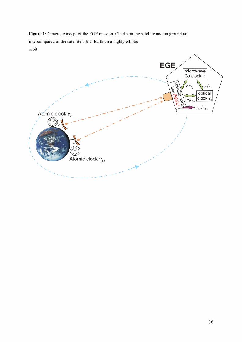
36
Figure 1: General concept of the EGE mission. Clocks on the satellite and on ground are
intercompared as the satellite orbits Earth on a highly elliptic
orbit.
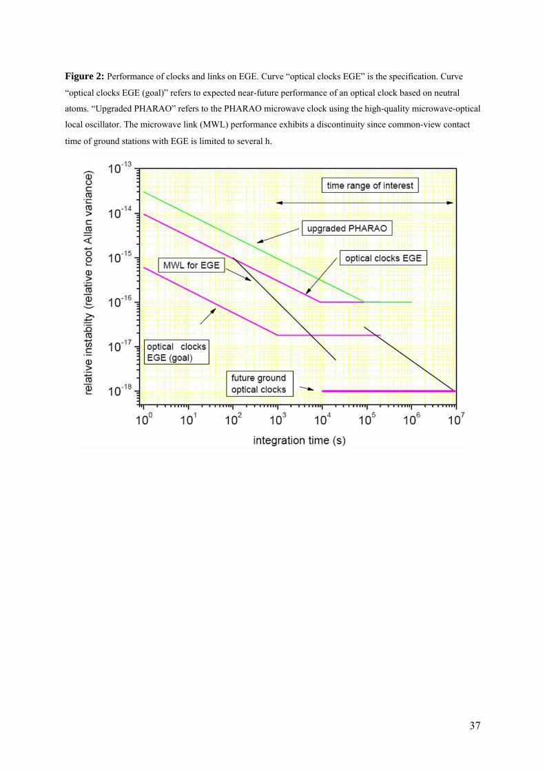
Figure 2: Performance of clocks and links on EGE. Curve “optical clocks EGE” is the specification. Curve
“optical clocks EGE (goal)” refers to expected near-future performance of an optical clock based on neutral
atoms. “Upgraded PHARAO” refers to the PHARAO microwave clock using the high-quality microwave-optical
local oscillator. The microwave link (MWL) performance exhibits a discontinuity since common-view contact
time of ground stations with EGE is limited to several h.
37
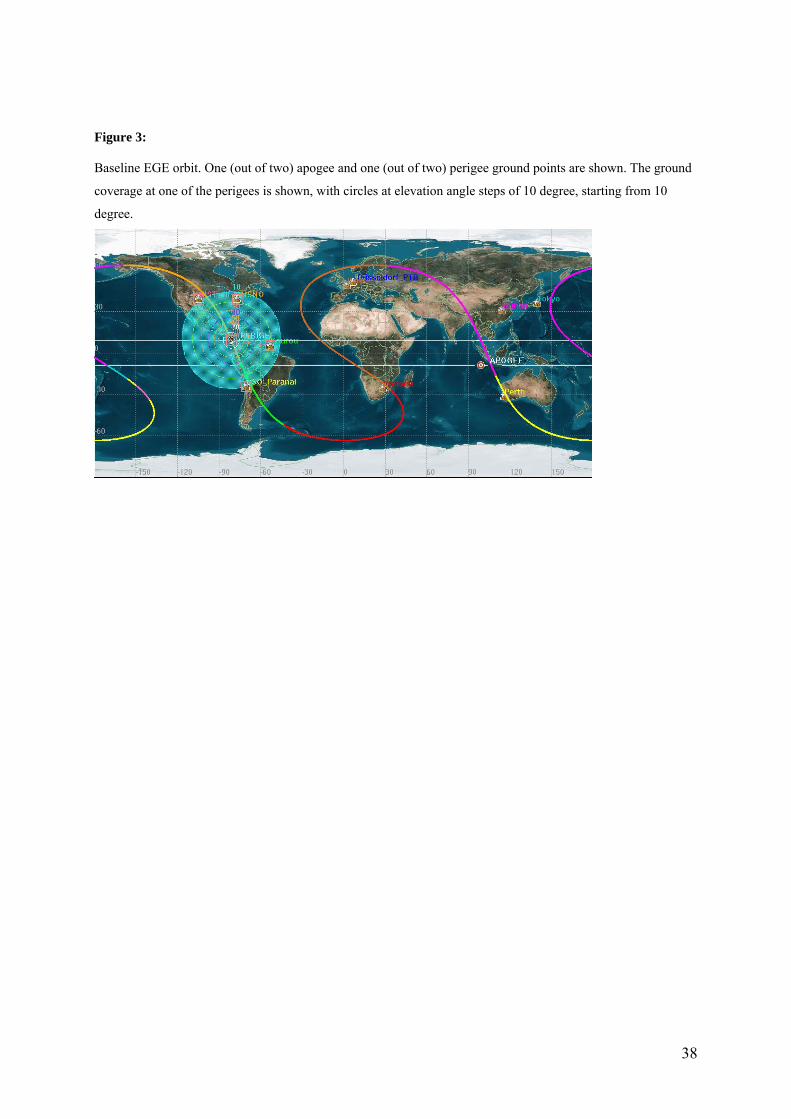
Figure 3:
Baseline EGE orbit. One (out of two) apogee and one (out of two) perigee ground points are shown. The ground
coverage at one of the perigees is shown, with circles at elevation angle steps of 10 degree, starting from 10
degree.
38
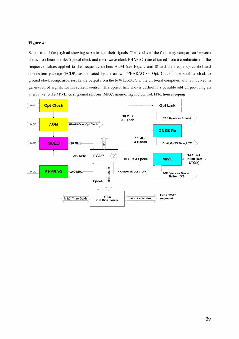
Figure 4:
Schematic of the payload showing subunits and their signals. The results of the frequency comparison between
the two on-board clocks (optical clock and microwave clock PHARAO) are obtained from a combination of the
frequency values applied to the frequency shifters AOM (see Figs. 7 and 8) and the frequency control and
distribution package (FCDP), as indicated by the arrows “PHARAO vs. Opt. Clock”. The satellite clock to
ground clock comparison results are output from the MWL. XPLC is the on-board computer, and is involved in
generation of signals for instrument control. The optical link shown dashed is a possible add-on providing an
alternative to the MWL. G/S: ground stations. M&C: monitoring and control. H/K: housekeeping
XPLCincl. Data Storage I/F to TM/TC Link
H/K & TM/TCto ground
Opt Clock
AOM
MOLO
PHARAO
FCDP
10 GHz
100 MHz
250 MHz
GNSS Rx
MWLT&F Link
uplink DataUTC(k)
T&F Space vs GroundTM from G/S
Tim
e S
cale
Orbit, GNSS Time, UTC
T&F Space vs Ground
M&C Time Scale
M&C
M&C
M&C
M&CM
&C
PHARAO vs Opt Clock
PHARAO vs Opt Clock
10 GHz & Epoch
10 MHz& Epoch
Epoch
10 MHz& Epoch
Opt Link
39
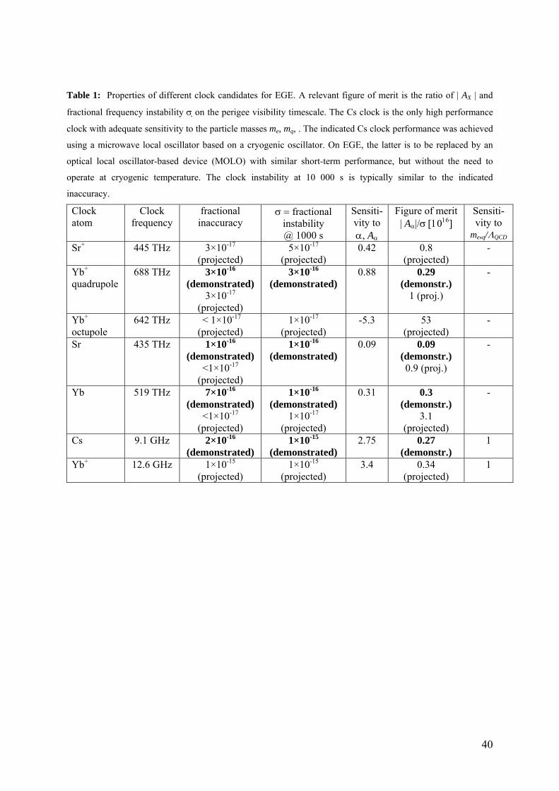
40
Table 1: Properties of different clock candidates for EGE. A relevant figure of merit is the ratio of | AX | and
fractional frequency instability σ on the perigee visibility timescale. The Cs clock is the only high performance
clock with adequate sensitivity to the particle masses me, mq, . The indicated Cs clock performance was achieved
using a microwave local oscillator based on a cryogenic oscillator. On EGE, the latter is to be replaced by an
optical local oscillator-based device (MOLO) with similar short-term performance, but without the need to
operate at cryogenic temperature. The clock instability at 10 000 s is typically similar to the indicated
inaccuracy.
Clock atom
Clock frequency
fractional inaccuracy
σ = fractional instability @ 1000 s
Sensiti-vity to α, Aα
Figure of merit | Aα|/σ [1016]
Sensiti-vity to
me,q/ΛQCD
Sr+ 445 THz 3×10-17 (projected)
5×10-17 (projected)
0.42 0.8 (projected)
-
Yb+ quadrupole
688 THz 3×10-16 (demonstrated)
3×10-17 (projected)
3×10-16 (demonstrated)
0.88 0.29 (demonstr.)
1 (proj.)
-
Yb+ octupole
642 THz < 1×10-17 (projected)
1×10-17 (projected)
-5.3 53 (projected)
-
Sr 435 THz 1×10-16 (demonstrated)
<1×10-17 (projected)
1×10-16 (demonstrated)
0.09 0.09 (demonstr.) 0.9 (proj.)
-
Yb 519 THz 7×10-16 (demonstrated)
<1×10-17 (projected)
1×10-16 (demonstrated)
1×10-17 (projected)
0.31 0.3 (demonstr.)
3.1 (projected)
-
Cs 9.1 GHz 2×10-16 (demonstrated)
1×10-15 (demonstrated)
2.75 0.27 (demonstr.)
1
Yb+ 12.6 GHz 1×10-15 (projected)
1×10-15 (projected)
3.4 0.34 (projected)
1
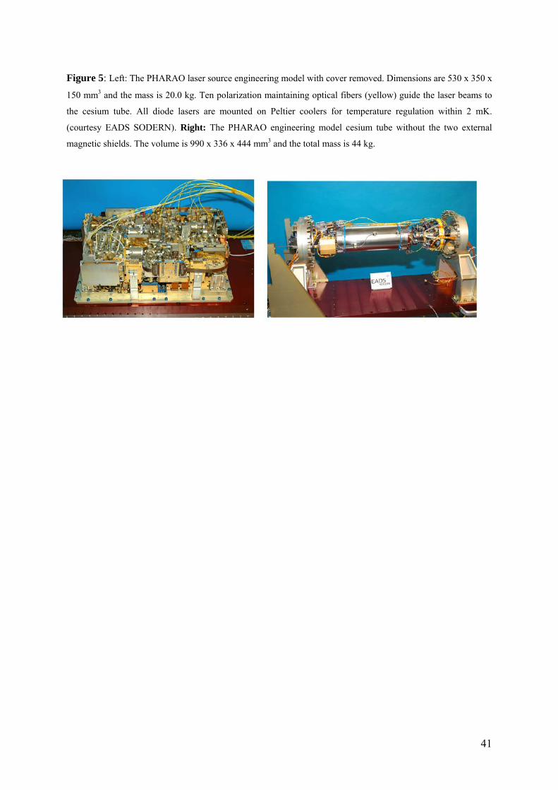
Figure 5: Left: The PHARAO laser source engineering model with cover removed. Dimensions are 530 x 350 x
150 mm3 and the mass is 20.0 kg. Ten polarization maintaining optical fibers (yellow) guide the laser beams to
the cesium tube. All diode lasers are mounted on Peltier coolers for temperature regulation within 2 mK.
(courtesy EADS SODERN). Right: The PHARAO engineering model cesium tube without the two external
magnetic shields. The volume is 990 x 336 x 444 mm3 and the total mass is 44 kg.
41
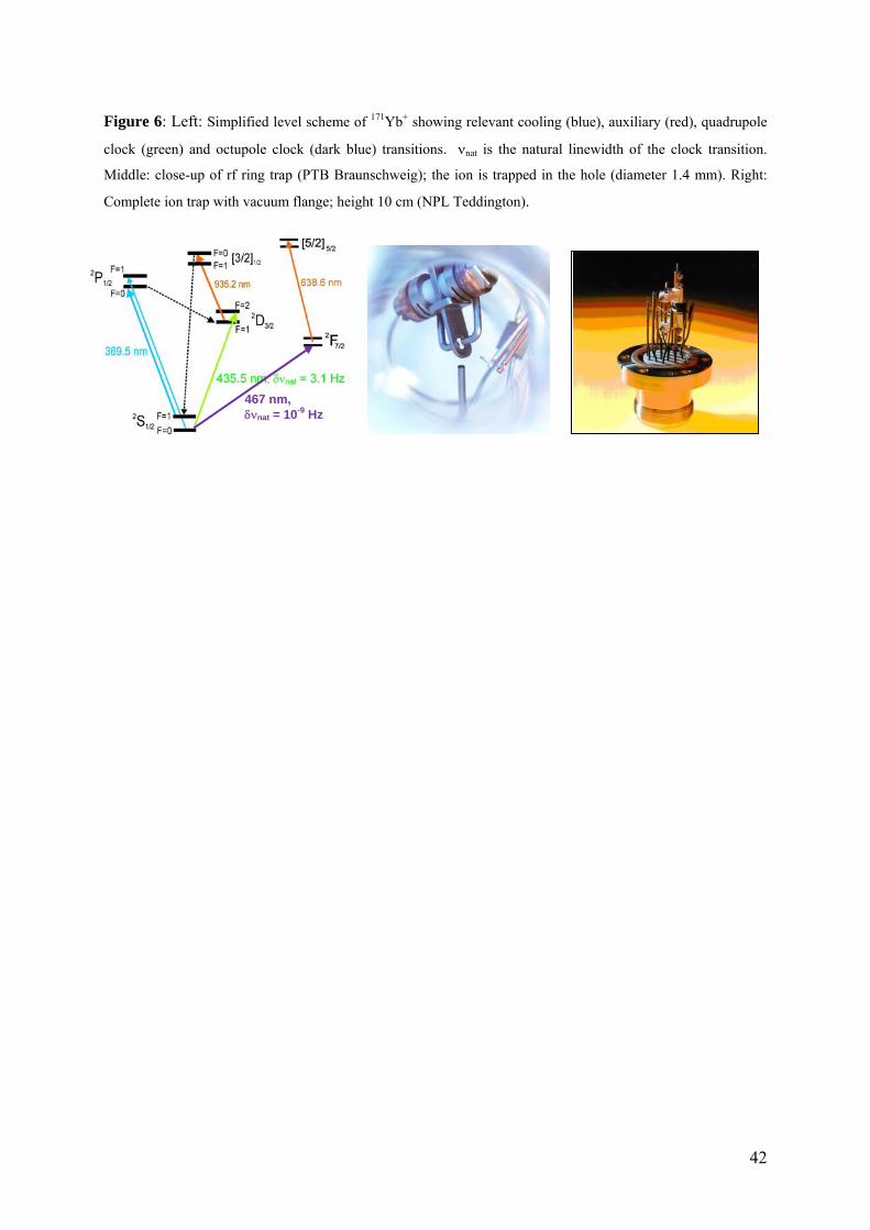
Figure 6: Left: Simplified level scheme of 171Yb+ showing relevant cooling (blue), auxiliary (red), quadrupole
clock (green) and octupole clock (dark blue) transitions. νnat is the natural linewidth of the clock transition.
Middle: close-up of rf ring trap (PTB Braunschweig); the ion is trapped in the hole (diameter 1.4 mm). Right:
Complete ion trap with vacuum flange; height 10 cm (NPL Teddington).
467 nm, δνnat = 10-9 Hz
42
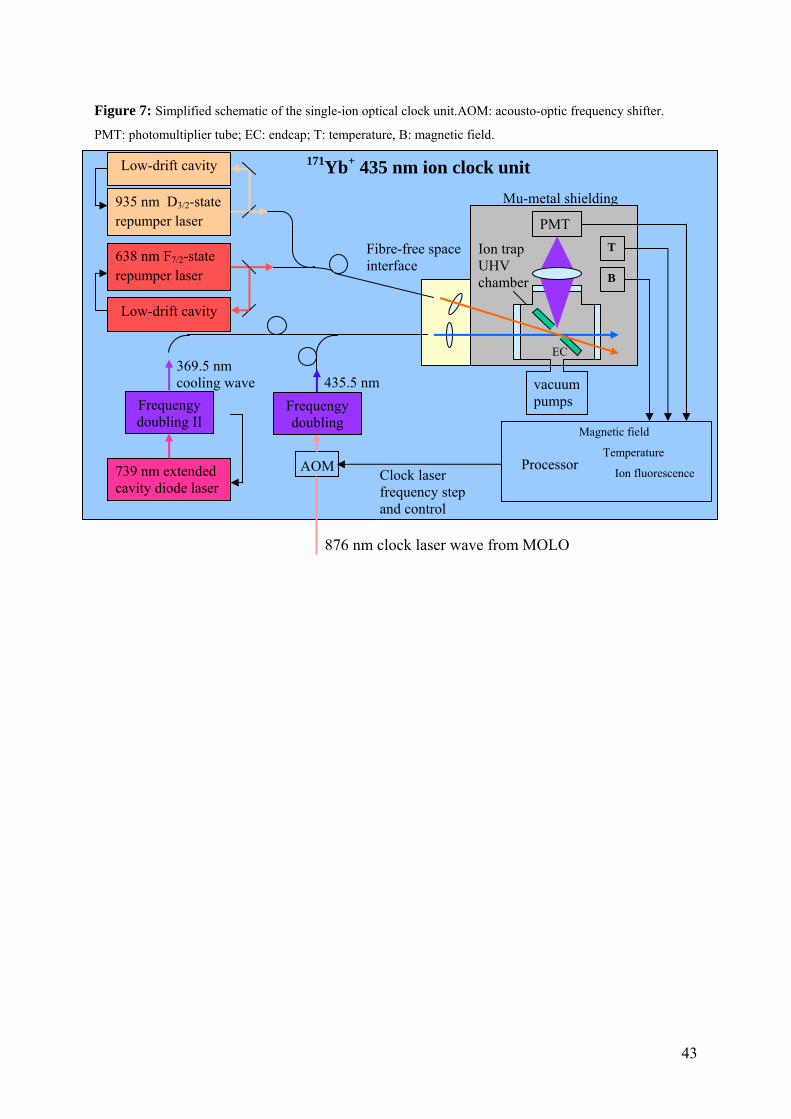
Figure 7: Simplified schematic of the single-ion optical clock unit.AOM: acousto-optic frequency shifter.
PMT: photomultiplier tube; EC: endcap; T: temperature, B: magnetic field.
935 nm D3/2-state repumper laser
638 nm F7/2-state repumper laser
739 nm extended cavity diode laser
AOM
PMT
Ion trap UHV chamber
vacuum pumps
Fibre-free space interface
Mu-metal shielding
EC
T
B
Magnetic field
Temperature
Ion fluorescence Processor Clock laser frequency step and control
435.5 nm Frequengy
doubling II
369.5 nm cooling wave
Low-drift cavity
Low-drift cavity 171Yb+ 435 nm ion clock unit
876 nm clock laser wave from MOLO
Frequengy doubling
43
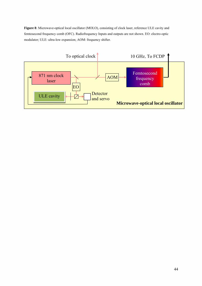
Figure 8: Microwave-optical local oscillator (MOLO), consisting of clock laser, reference ULE cavity and
femtosecond frequency comb (OFC). Radiofrequency Inputs and outputs are not shown. EO: electro-optic
modulator; ULE: ultra-low expansion; AOM: frequency shifter.
871 nm clock laser
ULE cavity
EO Detector and servo
AOMFemtosecond
frequency comb
To optical clock 10 GHz, To FCDP
Microwave-optical local oscillator
44
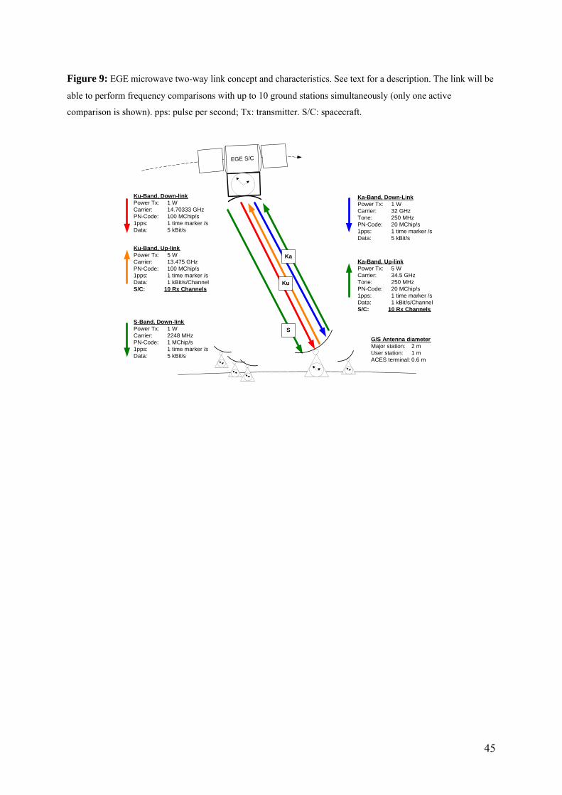
Figure 9: EGE microwave two-way link concept and characteristics. See text for a description. The link will be
able to perform frequency comparisons with up to 10 ground stations simultaneously (only one active
comparison is shown). pps: pulse per second; Tx: transmitter. S/C: spacecraft.
Ku-Band, Up-linkPower Tx: 5 WCarrier: 13.475 GHzPN-Code: 100 MChip/s1pps: 1 time marker /sData: 1 kBit/s/ChannelS/C: 10 Rx Channels
S-Band, Down-linkPower Tx: 1 WCarrier: 2248 MHzPN-Code: 1 MChip/s1pps: 1 time marker /sData: 5 kBit/s
Ku-Band, Down-linkPower Tx: 1 WCarrier: 14.70333 GHzPN-Code: 100 MChip/s1pps: 1 time marker /sData: 5 kBit/s
EGE S/C
S
Ku
KaKa-Band, Up-linkPower Tx: 5 WCarrier: 34.5 GHzTone: 250 MHzPN-Code: 20 MChip/s1pps: 1 time marker /sData: 1 kBit/s/ChannelS/C: 10 Rx Channels
Ka-Band, Down-LinkPower Tx: 1 WCarrier: 32 GHzTone: 250 MHzPN-Code: 20 MChip/s1pps: 1 time marker /sData: 5 kBit/s
G/S Antenna diameterMajor station: 2 mUser station: 1 mACES terminal: 0.6 m
45
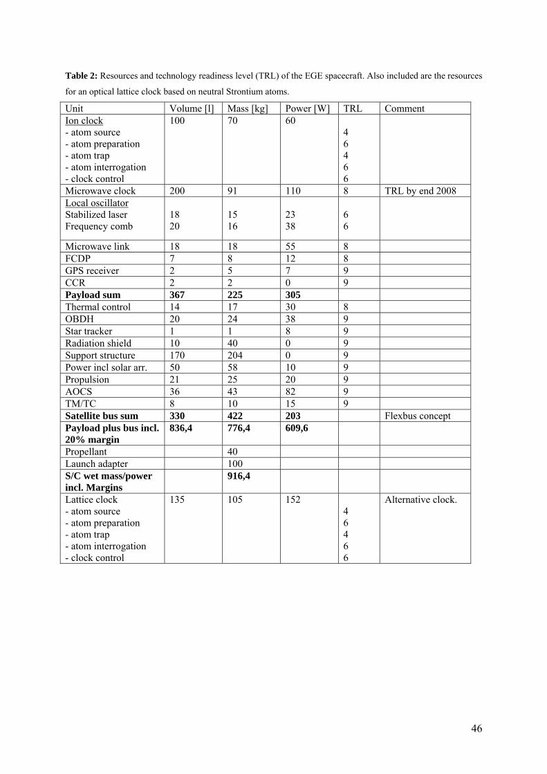
46
Table 2: Resources and technology readiness level (TRL) of the EGE spacecraft. Also included are the resources
for an optical lattice clock based on neutral Strontium atoms.
Unit Volume [l] Mass [kg] Power [W] TRL Comment Ion clock - atom source - atom preparation - atom trap - atom interrogation - clock control
100 70 60 4 6 4 6 6
Microwave clock 200 91 110 8 TRL by end 2008 Local oscillator Stabilized laser Frequency comb
18 20
15 16
23 38
6 6
Microwave link 18 18 55 8 FCDP 7 8 12 8 GPS receiver 2 5 7 9 CCR 2 2 0 9 Payload sum 367 225 305 Thermal control 14 17 30 8 OBDH 20 24 38 9 Star tracker 1 1 8 9 Radiation shield 10 40 0 9 Support structure 170 204 0 9 Power incl solar arr. 50 58 10 9 Propulsion 21 25 20 9 AOCS 36 43 82 9 TM/TC 8 10 15 9 Satellite bus sum 330 422 203 Flexbus concept Payload plus bus incl. 20% margin
836,4 776,4 609,6
Propellant 40 Launch adapter 100 S/C wet mass/power incl. Margins
916,4
Lattice clock - atom source - atom preparation - atom trap - atom interrogation - clock control
135 105 152 4 6 4 6 6
Alternative clock.