Embed Size (px)
Citation preview

AUSTRALIAN NATIONAL UNIVERSITY
DEPART~ffiNT OF NUCLEAR PHYSICS
14UD Tfu~K OPENING REPORT No.4l
15th to 23rd September 1983
(9 days open, 7 working days.)
REFERENCES: Earlier Tank Opening Reports are referred to by the notation(12/4) etc, meaning Report No. 12, page 4.
REASON FOR T~~KOPENING
The opening was scheduled because we were out of foils, also we hopedto complete the additions to the SF6 purification system by installing thenew 135 C.F.M. circulation pump and make some progress with the SF6 cooling.If, on examination, the chains continued to look good, then with the addedsecurity of upgraded purification, l,\Ie would put the new chain we had on handin the No. 1 position, where there has been no chain since early February.
PREAlvIBLE
The 14UD was last closed on 23rd June and went into use on a low voltagerun. At the end of the last report we wrote of encountering lost charge againquite soon. We described some ideas that came to us, (including fuzzballs),and tests that we carried out (40/8). Later, we evaluated the Vivalyme we hadremoved and found that it had much less moisture than virgin Vivalyme, thereforeit still had unconsumed drying capacity. This meant that the gas was dry, andthat moisture could not be the cause of the lost charge. As stated then (40/8),fresh Vivalyme and alumina banished the lost charge.
Towards the end of July, some uncertainties in measurements made with theShaw moisture sensor led us to question our technique and the location of thesensor on-line in the gas recirculation circuit. A new sensor head was installedon a separate chamber l,'lhich could 1), sample SF6 from various locations; 2),check the calibration of the detector and 3), confirm the zero setting. Althoughnone of us can understand why sensing the moisture in line, at tank pressure,shouldn't work, it doesn't.
Early in August we noticed charging problems with Chain 3. ~~en they persisted, we plotted charging current against volts on the inductors for the twochains, at first running together, and then running separately. For variousinductor voltages we found that Chain 3 was putting up only 60-65% of the chargingcurrent of Chain 2. Apart from that, all else appeared to be well and \\Ie tolerated the effect and continued running.
At regular intervals i'ie kept an eye on the level of breakdo""'Il products bymeans of the conductivity cell (37/5; 37/10) and established that this· parameter was remaining at a level which we regarded as consistent with a fullyeffective purification system.
The machine performed excellentlY,.running very reliably during July and
2/ .. ,

- 2 -
above 13.5 MV for about 23% of August, with three periods at 14.3 MV.
We had intended to take out the gas on Sunday, 11th September, but seriousand bewildering-problems developed with the gas handling system when tve beganto transfer gas. A pressure relief valve blew, dumping liquid SF6 into the gashandling room. When the operator ran to close the storage valve he discoveredthat the pipework near it was frozen. It was presumed that water in the pipefroze with expansion of SF6 and the expanding ice could have distorted theinternal structure of the ball valve, which of course was in the fully openposition when we began to transfer gas. We closed dO\ID for the day, aftersecuring everything, leaving the storage valve closed.
The following day, all gas in storage was transferred to the accelerator.The pipework to the storage ball valve was opened and about 750 ccs of brownwater came out.
When the ball valve itself was taken off, leaving an open pipe to atmos~
phere, we were impressed to discover that we were unable to pull open the doorof the storage vessel because of partial vacuum inside. Eventually somethinggave, and we got the door open. The younger author warned that there wouldbe some residual SF6 inside but, unable to resist a newly opened tank, theolder author stuck his head inside for a look, taking only one quick breath.He then pronounced, in a deep, sepulchral VOice, that it looked quite clean inthere. The younger author remarked, sarcastically, that one should always takea little helium with it.
We soon discovered that the pipe between the ball valve and the tank hadbeen full of wet, rusted scale which, at the last moment, was sucked up intothe tank. We cleaned the ·pipe\'iork and renewed the ball and gaskets in the valve.Apart from the sludge that had been in the pipe (about one imperial double handful, or 180 ml) the floor of the storage vessel was clean. The piece of sandblasted steel. angle left in the tank last t~mewas slightly rusted.
The sequence of events had been that the pipe onto the storage vessel hadbeen almost completely blocked. Expansion of liquid SF6 which did ,get past theblockage, caused the wet sludge to freeze and the pressure relief valve blewwhen the buildup between the compressor and the blockage reached the releasesetting.
Before we closed the storage vessel we made a sludge-proof dam, 6 incheswide and 2 inches deep and fitted it round the exit hole in the bottom of thestorage vessel.
Preparation for installing new type corona points.
The entire set of corona point assemblies in the machine, tube and column,were A.N.U. "rebuilds" (26/2) which were installed in June 1981 (26/4). Wereported (39/4) that we were not satisfied with the quality control of our own
. rebuilds. We gave up any idea of further l'homebrew" units and ordered a fullset of N.E.C.ts latest type corona assemblies. The design and constructionof the ne\v versions is an ingenious departure from types 2 and 3 assemblies,which had to be discarded in their entirety and replaced when they \"ere \vorn .
. The new assemblies incorporate holders which are common to both tube and·column and take discs into which are swaged three needles of appropriate length.The discs slip into the holders and are fastened by a special hand-held tool.The ease of assembly is indic~ted by the fact that Howard Wallace, (who is halfthe hawk-eyed duo which examines chains), fastened point discs faultlessly into
3/ ...

- 3 -
1200 holders in one working day with ease. In future we shall refer to thesecorona point assemblies as lType 4 1 because they are the fourth version (39/4)that N.E.C. has supplied. (Type 3 were experimental, and did not remain inuse.) .
There was one aspect of the Type 4 points that we did not 1ike at alL Thescrews which fix the assenlb1ies to tube and post electrodes in the earlierthree types were captive, whereas they are not in the ne\v units. Screws aresupplied separately, if you ask for them, and have to be inserted by the users.Hundreds of asseml)lies taken into the machine with loose screws would inevitablyshed some into the column during handling and the frustration of finding themwould be intolerable. To have to insert screws at the moment of installationwould be fiddling and time-wasting; also, the problem of shedding would beperpetuated for all future point changes because the same holders will now beretained forever - or until Type 5 comes along and there might not be captivescrews in those either.
We devised a crimping tool out of a pair of pincers, inserted the screwsin the holders and crimped them captive before the point discs were fastened.This task was accomplished by the undergraduates we employ to 'baby-sit' withlone experimenters during night shifts. We therefore had a complete set ofpoints for the entire machine ready for installation by the time tank was open,(or so we thought).
'-OPERATIONAL .,. TIME
During the 80 days since the last closure, the 14UD operated for 1722 hours.This was 89% of elapsed time, excluding the days for gas transfer.
THE TANK OPENING
The doors were opened at 5.15 pm on 14th September and the older authorabandoned his 65th birthday festivities, which had just begun, long enough totake the first 5niff in the tank. The air, being clear and excellent, allowedus all to attend to darkroom matters with an easy mind. When Trevor Ophel(37/1; 40/6) was reproved for not being present at the sniffing, he said: "Ididn't need to sniff; I knew it would be good because I've kept my nose on thegasoutfl ow from the moisture tests."
Exp16rat6ryt6ur.
Once in the tank we found the column to be reasonably clean, but there wasmore grey powder on shiny surfaces than we had hoped. The brO\ffi patch on theterminal was dry, and not very dark, and we could distinctly see p~tches corresponding to the triode needles. This must mean something, 1~'e're just not surewhat.
An early priority was to discover an excuse for the poor charging efficiencyof Chain 3 (page 1) and no sooner had we driven past the terminal than we founda d. c. idler lying on the floor of the first high energy unit. We lmvered theterminal and found that the idler had corne off the 'up' position of Chain 3 andtherefore was from the position feeding the "charge doubling" inductor. Thisexplained the behaviour of Chain 3. That the patron saint of charging chainsshould have shepherded this Fallen Idler to safety, without allo\ving its loosebehaviour to bring about the downfall of an innocent chain, left us profoundlygrateful.
4/ ...

- 4 -
We wrote earlier (40/6) that it would be sensible to perform, as soonas we got in the tank, the same tests that we carry out before closing themachine. In that way ''Ie could spot any time-consuming problems \vhile we wereable to organize them, rather than panic or slave through them at the lastminute.
Accordingly, we ran the chains and found, as we cruised up the column,that there was a serious oscillation, about plUS or minus three eighths ofan inch, in Chain :> between castings 16 and 19 where there are stabil izingidlers. The oscillation was predominantly in the 'stiff' direction - that isto say along the direction of the link coupling pins. There were no seizedor displaced idlers, though we felt that they were more closely set than is ourusual practice. We then observed Chain 2 and found it to be,running faultlessly.We adjusted the idlers on Chain 3, oiled the chain and rechecked for oscillation.There was no real improvement, but, with nothing further done, a retest after24 hours shm'led a marked improvement. During this period, idlers were checked.One bolton a double block ,vas found to be loose. The aluminium block had rubbedagainst its base plate producing material that coated the chain. Chain 3 wasmuch dirtier than Chain 2, presumably due to the aluminium dirt.
Before proceeding with anything else we began the now hallowed meticulouschain inspections. Approximately 10% of the nylon links in Chain 3 were foundto have cracks, whereas none had been seen in the equally meticulous inspectionat the last opening (40/5). The cracks were indistinguishable from those foundon so-called "breakdmvTI product attacked" chains; that is, the cracks were atthe transition between the neck and the head of the links where the curvaturewas sharpest and follmved machining marks. Finding the cracks was a considerableblow, because we had come to believe that our observation and control of breakdown products had put us well ahead in our efforts to resolve the long-standingchain problems.
Dispiritedly we began the examination of Chain 2. The gloom which had descended on us all was delightfUlly shattered when the Meticulous Examiners pronounced that no cracks at all had been found in Chain 2. We now had theinteresting situation that two virgin chains, installed at the same time, hadrun in the same atmosphere for almost an identical number of hours (about 3800)(One of them was distinctly the worse for wear while the other was, so far as we'could tell, like the driven snow. Surely even the patron saint of chains \vouldraise his eyebrows in questioning concern.
We feel this to be our first inescapable evidence that breakdown productsare not the sole, and perhaps not even the heavily predominant -cause of chainbreaks. We are glad \\le said (37/10; 40/7) that we would wait for betterstatistics before laying the blame solely on breakdown products.
Chain 3 appeared to have deeper machining marks on the nylon links. Thismight have been an illusion caused by the dirt revealing the marks, much .aslatent finger prints are revealed. Our chain inspectors are adamant that thesurface finish on the links of Chain 3 was worse than that on Chain 2.
In July 1982 we \ITote to N.E.C. suggesting that the nylon links might beless susceptible to mechanical failure if they were machined to a profile in\-!hich the necks were more smoothly contoured, (see sketch) . We believed thatthere was a stress concentration where the radius of curvature 1vas smallestand this was where we were seeing all our cracks. The idea was not pursued,but when Robert Rathmell was \vith us in June this year we discussed it at lengthwith him. Now, with the evidence of the two virgin chains before us our interest,wise or foolish, has revived. We telexed N.E.C. for a quote on the world's first
5/ ...

- 5 -
chain with hourglass links and N.E.C., helpful and co-operative with us asever, accepted the order cheerfully. In spite of the fact that laddertronsuse hourglass links, we shall still try them.
·Artd .so to 1\Tork!
·Chains.
We took out Chain 3. After checking the idlers carefully, we threadedin the last virgin chain we had, confirmed that it passed through the idlerpositions correctly and then ran it. An oscillation occurred at the same placeand to much the same degree as with the chain we had just taken out.
We took out all the spark shieldsfoT that chain with the intention ofmoving all the idlers well away from the chain so that its line from top tobottom was free from deflection. In order to set the idlers in Unit 16 thebolt holes had to be shifted a quarter of an inch. It soon became apparentthat almost all the idler blocks needed to be butchered savagely to align themto the chain. When our noses had been rubbed into the obvious long enough,even we finally realized that the chain was in the 1ITOng place.
This work occupied a considerable amount of platform time which we had nohesitation in allocating. When finally the chain was run again the youngerauthor pronounced that he was far from satisfied with the overall mechanicalperformance of the new chain, in spite of the work expended, and decided tocontinue investigations at the expense of the scheduled button-up.
The chain 1vas taken out. We then lowered the plumb-line and confirmedthat the terminal and driving pulleys were on the same vertical line. Thenext step was to carry out a pulley alignment starting from scratch. Themethod we grew up using has its origins far back in antiquity; our onlyremaining technician who worked on the installation remembers no other. Thehistoric technique is: a string is tied in the terminal· in such a 1vay that itruns tightly between the centres of the steel posts; the path of the stringdefines the position of the centre of the terminal pulley. Plumb lines suspendedfrom the string, t:ouching the centre of the groove, define the position of thedriving pulley in the bottom of the tank. Based on the same assumption thatmotivated the historic techniques the centre of the terminal pulley was seton the line joining the centre of the posts in the terminal. Plumb-bobs hungover the pulley in the centre of the groove were used to align the bottomdriving pulley. The chain was put back without any idlers in contact. Drivingdown the column to 'get the hang of it' the younger author noticed that thechain was not hanging in the centres of the chain holes in the castings. Ina unit part way down the column we related the line through the centre of thechain holes to that through the centres of the posts as follows: laying astraightedge so that it touched the insides of the bases of the posts wescribed a line on the casting. With the straightedge on the outside of theposts we scribed another line. We could see by eye that the chain holes werenot in the centre of the two parallel lines, but were closer to the outsideline. This meant that the traditional starting point for positioning thepulleys was in error by 0.15 inches, enough to account for our inability toget sufficient adjustment on the stabilizing idlers to position them in suitablerelationship to the chain.
Once again we made a new start, moving both·pulleys across 0.15 inchesand resetting the stabilizing idlers.
It was now apparent that the chain was not centred in the castings nearthe bottom. This misalignment was too great to be accounted for by the arc
6/ ...

- 6 -
moved by the motor mount. Indeed, we had to move the motor about 0.3 inchesaway from the pivot point to accommodate the chain at the centre of thecasting holes for the motor mount horizontal.· Judging from the dirt marks onthe pivot at tachmen t this misalignment has existed since the 1400 was installed.There is no point in describing all this trial, discovery and correction ingreater detail; suffice it to say that we ended up with Chain 3 running asclassically as Chain 2 which, presumably, had an accidentally better positionin life than Chain 3.
It is arguable that the chain developed cracks because of an axial misalignment of main pulleys caused by using the wrong datum. It is not clear when theconfusion over the datum occurred, or whether it exists at other chain positions.One might speculate that setting the stabilizing idlers more tightly thannormal turned this error into a problem. The type of cracks, identical to thosein "breakdown product attacked" chains, reinforces the view that mechanicalstress played a very important role in previous chain breaks.
Idl ers.
We had intended to remove all the A.N.D. idler supports, with theirbearing systems, and put back the N.E.C. versions (40/5) which we had beenpreparing; however, replacement components did not arrive in time and we delayedthis step. The idlers were reset to a considerable extent as mentioned abovein the discussion on chains.
Foils.
The terminal stripper unit was removed. The blank positions left to allowoperation of the Weisser valve, were some distance from the position indicatedby the counter. The inventor of the valve, however, has now become experiencedenough to operate it slowly, two or three times, across only part of its travel;by this means, foil frames in the way of the valve are displa~ed gently and fallto the floor of the stripper housing. To grasp the lever firmly, and close thevalve with complete confidence, can leave the hero stranded with a foil framejammed between the seals and the absolute necessity of letting the whole tubeup to atmospheric pressure. In this particular case, two foil frames weredislodged harmlessly. The Weisser valve sealed so well that the tube pressureof 8x 10⁻⁹ did not change ranges when the stripper was 'let up' and removed.Most of the 264 foils were changed.
Shaft ·bearings.
We listened to the shafts and concluded that there were no bearings whichneeded to be changed.
Points.
As we mentioned in the preamble, we had an entire set of new corona pointassemblies ready for installation, even down to captive fixing screws. Wedecided that we would at least put the L.E. set in, and, depending on hm'l otherthings were, might make a big push and do the H.E. end as well.
Whenever the platform fell vacant during all the work on the chains we tookout the old points (which had operated for 13,200 hours) and began putting in thenew ones.
7/...
- 7 -
It fell, of course, to the older author to be the first to start installingnew points and fail to get such a high percentage of them to screw on thatremarks began to be made about age, hearing and general incompetence; his·insistence that half the ne\~ screws must be blunt, or have left-hand threads,met with little c:redence and less sympathy, The introduction of someone youngand skilled in the art of screwing in screws, led, after his similar frustrationand confusion, to the discovery that the screws supplied for the new pointassemblies were a sixteenth of an inch shorter than the original ones. Insome cases they were not reaching the nuts in the brackets at all, while inother cases the screws were engaging by about one thread. It was our fault,of course; we (the older author) should have checked, but the new screwslooked so prim and correct, all 1370 of them, crimped in the shining new assemblies.
There was nothing that we could do except remove the short screws sopainstakingly crimped in the ne\'l assemblies and :replace them with longer scre\'lSequally painstakingly salvaged from the old assemblies, then recrimp. Sixpeople set to work with merry hearts and the place echoed with chuckling andcheerful banter over N.E.C.'s wry and unexpected little tease. We all had toadmit that it was the most hilarious thing since star-headed screws.
We were glad that we had made up two alignment tools for tube and columnassemblies according to Robert Rathmell's design (40/5) because, by their use,we succeeded in getting all the tube and column point assemblies level andcorrectly spaced. Theyounger author was so enthusiastic about uniform pointspacing that he personally set all the points in the machine, including thosealready set by the older author.
When we had finished we were very impressed by the uniformity of the totalinstallation. We gladly record, also, that the manufacturing and quality ofType 4 assemblies were really excellent. Additionally, there was a comfortingfeeling that the next time we need to change all the corona point assemblies,we shan't have to throw entire assemblies away, even if it means a bit ofslavery to replace the bits and do the job .
. Insulating gas.
A Shaw moisture sensor was put on the recirculator output at Level 3 withadditional plumbing to flush room air past it. We have been in touch withShaws, who were very good to us. We put in a brand new sensor which calibratedcorrectly, but when we put it on line it saturated. We are confused and are notprepared to say any more than that about it for the time being ..
Breakdo\ID products.
In August 1982 we put some nylon cable ties in the bottom of the machine,fastening them with a 'gun' set on standard tension. We tested the ties on thisoccasion and found them strong and resilient, exhibiting no brittleness.
Miscellaneous
Unfortunately, in spite of a magnificent effort by N.E.C. to get the newrecirculator pump to us in time, it arriv.ed too late for all the work involvedto be completed. We have to admit that, even if the blower had arrived in time,the considerable amount of work with Chain 3 and its idlers would have commanded
8/ ...

- 8 -
too much manpower for work on the purifier to have been completed.
Cl eaning.
Because every unit had been opened, the floors, ceilings and furnitureof all of them were tacragged. After the rings were put back the column wasblown with nitrogen and there \'las another run over the rings 'with tae-rags•
.Button-up.
The chains were run once again and studied. The charging tests wereeopybook.
Initial ·performance.
The machine was rock steady. The corona currents were steady, but muchhigher than before the new points were put in. It was not until the machinewas operating that the grossly larger corona point currents led us to comparethe point to plane gaps of the Type 4 assemblies with some unused Type 2assemblies which we have kept as standards; eN.E.C. originals, not A.N.D.rebuilds). For the eolumn assemblies the point to plane gap has beenredueedfrom 12.9 rum to 11.4 rum. For the tube assemblies the gap is reduced from 4.2 ~to 3. 7 mm. This geometry produces record-breaking breakdo\ffi product productiorlrates. For these measurements we have assumed that the needles are stilleffectively facing a plane surface and that the concave cups holding the adjacentpoints don't make up for the apparently smaller gaps. Certainly the highercurrents support this assumption.
There was no difficulty in getting up to voltages required ilmnediately andin a few days the lAUD was running at 13.5 MV.
D.C. Weisser
T.A. Brinkley
11th October, 1983.
The l4UD Tank Opening Reports are circulated, by request, to the followingpeople:
Dr R. Rathmell, N.E.C.
Dr R. Voss, S.E.R.C.
Dr J. Ball, Oak Ridge.
Prof. S. Skorka, Hunich.
Dr N. Burn, Chalk River.
Dr H. Munzer, ~~nich.
Dr A. Vermeer, Utrecht.
Dr R. Siemssen, Groningen.
Mr C. Kobayashi, J.A.E.R.I.
Dr T. Aitken, Daresbury.
Prof. E. Skurnik, Israel,
Dr R. Repnow, Heidelberg.
Prof·. K. Kemper, Florida State Univ.
Dr C. Jones, Oak Ridge.
Dr H. Wegner, BroOkhaven,
Dr W. Kutschera, Argonne.
9/ ...

Mr R. Mck. Hyder, Oxford,
Dr J. Yntema, Argonne.
Dr D. Bohne, Darmstadt.
Dr R. Hellborg, Lund lnst.
Prof. C. Barnes, Cal tech.
Dr P. DenHartog, Argonne.
Dr J. Noe, Stony Brook,
Dr K. Katori, Osaka Univ.
Dr C. Hoak} Oak Ridge.
Dr W. Henning, Argonne.
Dr K. Prasad, Tata lnst.
Prof. H. Hubel, Bonn.
. .EnClosures:
- 9 -
Prof. S. Seki, Univ. Tsukuba.
~rr T. Lund, Univ. Rochester.
Dr M. Letournel, Strasbourg.
Prof. O. Sala, Univ. Sao Paolo.
Prof. T. Trainor, Univ. Washington~
Dr S. Signorini, Padua.
Dr M. Mariscotti, Argentina.
Dr R. Sparks,DSlR, New Zealand.
Dr B. Spellmeyer, Hahn-Meitner lnst.
Mr P Asbaugh, Mcl\!aster Univ.
Dr V. Hattangadi, Bhabha lnst.
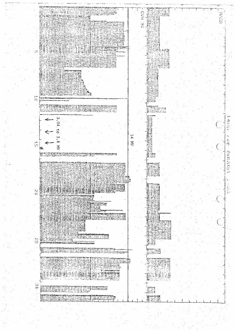
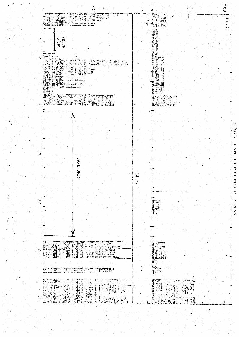
Plots of particle masses accelerated, and operating terminal voltages.
NOTE: On the plot of terminal voltages we have dralill a horizontal line at14t1V for easy reference to performance near the nominal voltage limitof the 14UD.
Sketch of "hourglass" profile for nylon chain links.

,,,,--,,•I
III,IIII,..
''''-. -
"HOURGLASS" LINKS
Solid line: proposed contour.Dotted line: existing contour.

''':;:
---T'--r'--'T---!--'-T-'-":~-T'--l~:l
:> t
gli
,I
JI
!-1I~
·iI-l!~!
~1
f1
I,! ~....,;! ;;..! ~
-l'=I £:;:;i
-I! ;":-1[
~"i--i
i•."'1~..
jI t •
1 -='}
=I "'::il
I --, j
I ~
1i,
~.~
(
JI
i
1~t
I
-il;]]JI
mo..;:'fc:;r:!:t"-::_--ll__-..L!_-J'-_....._ .....
~i~~iifHTIm~~I~IT1.ml-\l ,-_~~1~\'~~.~ilm~~5:f~~
~1m1m!n~l'HnTIT7lIT1~mLl!iJ[;n~IfrtlffIfr~'IT{~~~;;;;; --I,.~';';:~;.F.:~£:.~:rt·~·i. -~.
~#J.:Ee...~~ffii.~'5\~:\?.~~~~~"=~U;:::::"'~~~W=-~__ ~__5:;~~==-..:==..~l-'
~~[f:r~li
~.
.~ tN
at .j::>.
l <::- rtI 0III tN.I;-
:-:>. ~00
:J1~ :;
-,
· \
:-...ul
~7<:
.....0
..".'-0tTl
.-,.Z
<
::..:
JII
+
•••:0,;