Embed Size (px)
Citation preview
Australia 51.25 New ZealillX/ $1 30 Malaysia $4.95 IR EOp lint. VAT)
AIDF;C
tnEtvg
(U.Kira% 014X) !Jo n
. 440.A.30
oil
introduction -toROBOTICS Roto,cum
-NOCTiVE I:1;h CA ITIOICSYSTEM

Quite simply the best way to make music...Prices to suit every pocket
Complete Kits from f33-£320
I
TRANSCENDENT 2000 PIM°
t 1 a
3,-)4J44.14
COMPREHENSIVE INSTRUCTIONS WITH EVERY KIT KITS REALLY COMPLETE-EVEN SCREWS AND WIRE!
SUPERIOR MATERIALS SUPERIOR FINISH SUPERIOR SOUND
AND REMEMBER DIY SAVES YOU Es
. . . build the TRANSCENDENT range from POWERTRAN
WORLD LEADERS IN ELECTRONIC KITS
MONEY BACK GUARANTEE If you, are not completely satisfied with your Powertran Kit, returnit in original condition within 10 days and we will refund your money
SOLDERING PRACTICE KIT- FREE on request with your first kit, to assist newcomers!
PORTWAY INDUSTRIAL ESTATE, ANDOVER, HANTS SP10 3WN. ANDOVER (0264) 64455

PRACTICAL
ELECTRONICSVOLUME 17 No. 10 OCTOBER 1981
CONSTRUCTIONAL PROJECTSHOROLOGICUM STAR CLOCK byJ. S. B. Dick 22Extra -terrestrial time keeping made easyHEADPHONES WITH A DIFFERENCE by A. B. Bradshaw 36Improves the presence of personal stereoINDUCTIVE DISCHARGE CAR IGNITION SYSTEM by K. Wevill 40Contact breaker, breakerless and extended dwell circuitsPE RANGER Part 2 by Michael Tooley BA. and David Whitfield MA., M.Sc 50Circuit description and constructionPE PULSER by Tom Gaskell BA. . . . . . . . . . . . . . . 62An all-purpose design for CMOS and TTL, incorporated in our Digital Design Techniques seriesAUDIO ANALYSER Part 3 by Michael Tooley B.A. and David Whitfield MA., M.Sc 67Self-contained noise source and microphone pre -amp circuits
GENERAL FEATURESINTRODUCTION TO ROBOTICS by Professor Wilfred Heginbotham O.B.E. D.Sc 30A look at robots used in industrySEMICONDUCTOR UPDATE by R. W. ColesFeaturing OPL100 WD55 LM396DIGITAL DESIGN TECHNIQUES Part 3 by Tom Gaskell BA. 58Touch switches, timers and oscillators
NEWS AND COMMENTEDITORIAL .. 17NEWS & MARKET PLACE 18Including CountdownUSING YOUR FREE IC REMOVAL TOOL 20INDUSTRY NOTEBOOK by Nexus . . 21Advice for the young unemployedSPACEWATCH by Frank W. Hyde . . . . .. . . . . . . 48Sunspots and the earth's climate A second visit to Saturn-Dynamics Explorer missionSPECIAL OFFER-IN CAR ENTERTAINMENT 49PATENTS REVIEW 73SPECIAL OFFER-GSC EXPERIMENTOR KIT 73
OUR NOVEMBER ISSUE WILL BE ON SALE FRIDAY, 9 OCTOBER 1981(for details of contents see page 57)
© IPC Magazines Limited 1981. Copyright in all drawings, photographs and articles published in PRACTICALELECTRONICS is fully protected, and reproduction or imitations in whole or part are expressly forbidden. All reasonableprecautions are taken by PRACTICAL ELECTRONICS to ensure that the advice and data given to readers are reliable. Wecannot, however, guarantee it, and we cannot accept legal responsibility for it. Prices quoted are those current as we goto press.
Practical Electronics October 1981
WATFORD ELECTRONICS33/35, CARDIFF ROAD, WATFORD, HE RTS, ENGLAND
Tel. Watford (0923) 40588. Telex: 8956095ALL DEVICES BRAND NEW. FULL SPEC. AND FULLY GUARANTEED. ORDERSDESPATCHED BY RETURN OF POST. TERMS OF BUSINESS'CASH/CHEQUE/P.0. OR BANKERS DRAFT WITH ORDER. GOVERNMENTAND EDUCATIONAL INSTITUTIONS OFFICIAL ORDERS ACCEPTED(TELEPHONE ORDERS BY ACCESS NOW ACCEPTED Minimum £10.00 pass.),TRADE AND EXPORT INQUIRY WELCOME. P & P ADD 50p TO ALL ORDERSUNDER f10.00 EXCL. VAT. OVERSEAS ORDERS POSTAGE AT COST.
ed." no :kPt i.b.toUl(u°4.r'onj9.:.ATotheise, 11rics aetsclusiveof 5AT.7easeal 156othe total cost incl. p&p.
We stock many more nom.. It pay to visit us. We are situatad behind WatfordFootball Ground. Near... Underground/Br. Rail Station: Watford High Street. OpenMonday to Saturday 9 a.m.-6 p.m. Ampla Free Car Parking space availabla.
POLYESTER CAPACITORS: Axial Load typo)400V: 1 'IF. 1n5. 2n2, 3n3, 4n7, 6n8 11p; 10n. 15n. 18n. 22 120; 33n, 47n. 68n 16p;100n, 150n 20p; 220n 30p; 330n 42p; 470n 52p; 680n 60p; 1pF 68p; 2p2. 4p7 85p.160V: lOnF 12n 100n 11p; 150n. 220n 17p; 330n, 470n 30p; 680n 38p; 1pF 42p; 1n549; 2p2 46p; 407 Up.MOP: 1nF 17p; 10nr 30p; 15n 40p; 22n 36p; 33n 42p; 47n, 100n 110p.POLYESTER RADIAL LEAD CAPACITORS: 250V; FEED THROUGH10n 15n 22n. 27n 6p; 33n 47n, 68n, 100n 7p; 150n. 220n 10p; CAPACITORS330n 470n 13p; 680n 19p; 10 23p; 105 40p; 202 46p. 1000pF Sp
ELECTROLYTIC CAPACITORS (Values in pFL 500V: 10 62p; 47 780; 63V: 0,17, 1 0.
70P; 60V: 47 12p; 68 ; 220 24p; 470 32p; 2200 110p; 40V: 4 7. 15, 22. ; 3301 5. 2 2. 3 3. Sp; 4 7 Il6 8,
31400
10p; 15. 22 12p; 33 15p; 47 2p; 100
90p; 470120p; 26V: 1 . 6 8, 10,22 Sp 33 11p; 47 12p; 22 15p;330 22p;4702 6p; 680, 1000 34p; 2200 150W300 7 ; 4700 5 ; 111V:40.47. 100gp; 125 1 220 13p; 470 20p; 680 34p; 1 27p; 1 00 31p; 2 00 3111p; 3300 749;4700 711p.TAG -END TYPE: 70V: 4700 243p; 64V: 3300 1980; 2200 139p; 50V: 3300 11140;2200 110p; 40V: 4700 1605; 25V: 10.000 320p; 15.000 346p.
UM BEAD CAPACITORS:35V: 0 10, 0 22 0 33 150; 0 47.0 68.
1 0, 1 5 16p; 2 2. 3 3 18p; 4 7. 6 822p; 10 211p; 16V: 2 2. 3 3,11Ip; 4 7,6 8. 10 18p; 15 369; 22 30p; 33, 47
26p;33 4710 735p; 105p;2200 88p 10V: 15. 22
MYLAR FILM CAPACITORS:100V: lriF, 2n. On, 4n7. 10 6p; 15nF,22n, 30n. 40.47 7p; 56. 100n. 20011p;470n/50V: 12p.
CERAMIC CAPACITORS: (50V)Range 0 5pf to lOnF 4O15nF 22nF, 33nF, 47nF Sp100nF/30V 7p; 220nF/6V Sp
POTENTIOMETERS: Carbon Track.0 25W Log & Linear Values.5000.1K & 2K ILIN ONLY( Single 26p5K0 -2M0 single gang 29p5K0 -2M0 single gang D/P switch 78p5K0 -2M0 dual gang stereo 88pIW Wire -wound 500-20K 115p
SLIDER POTENTIOMETERS0 25W log and linear values 60mm track'KO. 500(0 Singh" gang 70p10(0. 500(0 Dual gang 110pSelf -Stick graduated Alum. Bezels 36p
POLYSTYRENE CAPACITORS:10pF to 1nF Bp I. 5nF to 12nF 10p.
PRESET POTENTIOMETERS0 1W 500-2 2M Mini Vert. & Hon,. 7p0 25W 1000-3 3M() Hon:. larger 10p0 25W 2500-4 7M° Vert. 10pPrecision Cermet 1W 1000-100K SOp
SILVER MICA Ion2. 3 3. 4 7, 6 8. 8 2. 1012. 18. 22. 27, 33. 39.47, 50. 56. 68. 75. 82.85. 100. 120. 150, 180
15p each220. 250. 270. 330.360. 390. 470. 600.800 & 820pF 21p oath1000. 1200. 1800
30p each3300.4700 60p each
SIEMENS mu Weyerminiature capacitors.250V: 1nF. InS. 2n2.3n3. 4n7, 6n8, 8n2.10n, 12n. 15n. 22n 7p18n. 27n, 33n. 47n Sp39n, 56n, 68n 9p100V. 100n. 120n, 10p;150n 1p; 220n 13p;330n Sp; 470n 23p;680n 30p; I6F 34p;292 50p.
RESISTORS -Eno maks 5% carbonMiniature High Stability. Low Noise.
RANGE Val 1-99 100.0 25W202-4 M7 E24 Sp 1p0 5W 202-4 M7 E12 2p I p1W 202-10M E12 Sp 3p2% Metal Film 100-1M 8p 4p1%0 5W 510-1M24 Sp 6p
100+ price applies to Resistors ofeach type not mined values.
LINEAR IC's555 CMOS 80702 75709C 8 pin 35710 48741 14747C 14 pin 787480 8 pin 38753 8 pin 185810 1599400CJ 350AY -1-0212 675AY -1-13134 660AY -1-1320 225AY -1-5050 99AY -I-5051 160AY -3-1270 840AY -3-8500 390AY -3-8910 720AY -3-8912 625AY -5-1224A 235AY -5.1230 450AY -5-13174630AY -5-8100 775043011 110CA3012 175CA3014 157CA3018 68CA3019 70CA3020 186CA3023 191CA3028A 80CA3035 235CA3036 115CA3043 275CA3045 365CA3046 70CA3048 214CA3059 195CA3075 213CA3080E 65CA3081 190CA3089E 215CA3090A0 375CA3123 150CA3130 90CA3140 48CA3160 95CA3189 295ICL7106 795ICL7107 975ICL8038CC 340ICL8211 150ICM7205 1150ICM7207 475ICM7215 1050ICM7216A 1950ICM7216B 1950ICM7217A 790ICM7224 785ICM7555 80LA4032 295LC7130 496LD130 462
LF351LF355LF356LM10LM301ALM308LM311LM318LM324LM339LM348LM349LM358LM379LM380LM381NLM382LM384LM386LM387LM389LM733LM2917LM3900LM3909LM3911LM3914LM 3915LM3916LM 13600
as8590
395269570
200506890
11550
41580
14512514099
1209975
1956070
125220220240135
LS7220 280M252AA 625M253AA 1150MC1303 88MC1304P 260MCI310P 150MC1445 150MC1458 45MC1494 894MC1495 350MC1496L 92MC1596 225MC1648 290MC I 709G 90MC1710 79MC3302 150MC3340P 120MC3380P 120MC3401 52MC3403 89MC3405 150MFC6040 97MK50398 635MM5303 835MM5307 1275MM5387A 475MSM5526 820NE529 225NE543 210NE544 185NE555 16NE556DB 55NE560 325NE561 395
NE562B 410NE564 435NE565A 120NE566 180NE567 170NE570 450NE571 420RC4136D 6955868 245SA83209 425SAB3210 275SAB3271 485SG3402 295S5760035 240SN76018 148SN76013N 250SN76023N 170SN76033N 195SN76115N 215SN76131 125SN76227N 95SN76477 175SN76660 120SP8629 299TA7205A 225TAA621AX1 250TAA661A 155740100 159TBA120$ 70TBA5500 330TBA641-Al2'8X1 or 8X11250TBA651 190TBA800 90TBA8105 95TBA820 70TBA9200 260TCA965 1207041004 290TDAI008 310TDA1022 575TDA1024 105TDA1490 2907042020 320TDA2030 320TL061 46TL064CN 159TL071CP 45TL072CP 70TL074CN 125TL081CP 42TL083CP 957L084CP 105UAAI70 170U44180 170U4A1003-3 935ULN2003 100XR2206 300XR2211 575XR2266 750ZN414 95ZN423 196ZN424E 130ZN425E 350
25426ZN427ZN428ZN429ZN1034E251040E
325625478210200885
COMPUTERIC'S
2101-2 1102112-2 2502114-450 992114L -300n 992114L -200n 1302118-3 2502532-450n 7502708 2252716-5V 2502732-450n 7252147 004027 2404116 994118-250 5304315-4K 9954334-3(CMOS 2114)3264864-3 C126502 CPU 4956503 8506505 7956520 PIA 3256522 VIA 4956530 RRIOT 13506532 RIOT 7956545 CRTC 14506551 ACIA 7856592 PC E266803 13506805 6706800 3756808 5206116-3 16KCMOS RAM 9506802 56809 E1350
6810 1756821 1756840 4706843 14506845 E126850 1756852 2256875 5508080A 4508085A 550811.595 115 TTL 74008115981LS97 115 (TEXAS)8212 210 7400, 118214 425 7"..1 118218 200 '7402 118251 400 7403 148253 799 7404 14
7405 15
8257 8008726A 1358728A 1358731 3508795N 1358797N 135AY -3-1015 395AY -5-1013 350AY -5-2376 700IM6402 380MC1488 62MC1489 62MC14411 695MC14412 800RO-3-25130 600SFF96364E 950SFC7I301 820TMS2716-3V 875TMS4027 240TMS6011 365280CPU 2 5 390280ACPU 4M 550280 PIO 400280A P10 440Z80 CTC 400280A ETC 440Z80510-1 f15ZEIOAS10 E23Z80 DART 726Z8OA DART 77574S132 138745138 24074S188 210745189 15874S194 360745241 54074S262 850745287 32574S288 210745470 32574S472 1150745475 825745201 62074S471 620745571 62075150 14075108 35075154 15075188 6575189 6575322 16575450 9575451/2 7075454 22675491/2 70
TRANSISTORS BFR39/40 23 0C200 55 2N708 19 255194 80AC107 35 BC214L 10 BFR41/79 23 TIP29A 36 25914/5 32 2N5305 24AC125 38 BC237/8 14 BFR80/81 26 TIP29C 80 25918 35 2N5457 36AC128 25 BC307B 14 8FR98 105 TIP30A 48 2N930 20 255458/9 38AC127/8 25 BC308B 16 BFX29/84 25 TIP30C 58 251131;2 24 2N5485 36AC141 30 BC327 15 8FX85/86 21 TIP31A 45 2513034 85 2N5777 45AC142 30 8C328 16 BFX87/88 215 TIP31C 55 2513057 60 2N6027 32AC176 28 8C337,8 16 BFY50/51 23 TIP32A 48 251308 68 2N6109 80AC187/8 28 8C441 34 BFY52 23 TIP32C 60 251613 30 2N6290 70ACYI 7/18 70 BC461 34 BFY56 32 TIP33A 65 251671B 160 2SA715 60ACY19/20 75 8C477'8 40 BFY64 35 TIP33C 78 252160 295 2SC495 70ACY21/22 75 8C516 40 BFY81 120 TIP34A 74 2N22 19A 28 2SC496 70ACY28 75 BC517 40 BFY90 SO TIP34C 88 2N2220A 26 2SC1096 85A0149 79 8C5478 14 BRY39 40 TIP35A 160 252271A 26 2SC1173 125AD161/2 42 BC549C 14 8SX20 20 TIP35C 185 2N2222A 25 2SC1306 150AF118 95 BC556/7 16 BSX29 34 TIP36A 170 2523694 18 2SC1307 220AF139 40 BC558/9 15 BSY95A 26 TIP38C 199 2N2646 45 2SC1449 85AFI 78 75 BCY70 16 BU105 170 TIP41A 55 252846 80 2SCI678 1408C107 10 BCY71/2 20 BU108 240 TIP418 60 2N2904 28 2SCI923 50BC1075 12 BD121 95 BU109 210 TIP42A 60 2N2905A 28 2SC1945 2258C108 10 8D124 115 BU205 190 TIP42B 75 2N2906 26 2SC1953 90BC108B 12 130131,2 48 BU206 200 TIP120 90 2N2907A 28 2SC1957 90BC108C 12 B13133 60 8U208 200 TIP121 99 2N2926G 10 2SC1969 198BC109 10 80135 45 E421 250 TIPI41 120 2N3053 26 2$C2028 85BC10913 12 80136.7 40 MD8001 250 TIPI42 120 2N3054 58 2SC2029 180BC109C 12 BD138 9 40 MJ2955 90 TIP147 120 2N3055 48 2SC2078 155BC117/8 20 BD140 40 MJE340 64 TIP2955 80 2N3442 140 2SC2091 85BC140/42 30 8D144 198 MJE370 100 TIP3055 80 2N3565 15 2SC2314 85BCI 43 30 BD205 110 MJE371 100 T1S43 32 2N3614 199 2SC2166 165BCI 47 9 80245 415 MJE520 95 TIS44/45 45 2N3615 199 2SC1679 190BC147B 10 80378 70 MJE2955 99 TIS48 50 2N3663 16 250234 75BC148 9 BD434 55 MJE3055 70 71$88A 50 2N370213 10 2SK45 90BC1488 10 80517 76 MPF102 66 71590 30 2N3704/5 10 3N128 1128C148C 10 8D695A 99 MPF103 36 71591/93 32 2N370617 10 35140 112BC149 S BD696A 99 MPFI04 36 UC734 85 2N3708/9 10 40097 88BC149C 12 80Y56 180 MPF105 36 VK1010 80 2N3710 10 40100 215BC153/4 27 8DY60 160 MPF106 40 VN1OKM 45 2N3711 10 40101 130BC157/8 10 61115 35 MPSA05 25 VN46AF 78 2N3771 179 40250 85BC159 11 81167 29 MPSA06 25 VN66AF 85 2N3772 195 40251 97BC160 45 131173 27 MPSA12 32 VN88AF 94 2N3773 270 40311 80BC167A 10 E11177 25 MPSA55 30 ITX107/8 11 2N3819 22 40313 130BCI68C 10 81178 30 MPSA56 30 Z7X109 12 2N3820 45 40315 60BC169C 10 81179 36 MPSA70 30 ZTX2I2 28 2N3822/3 65 40316 95BCI70 15 81180 ss MPSUO2 58 ZTX300 13 2N3866 90 40317/20 80BC171/2 11 81194 5 12 MPSUO5 66 ZTX301/2 16 253903/4 18 40360 40BC173 11 81196 7 12 MPSUO6 55 ZTX303 26 253905 15 40361/62 60BC177/8 20 01198 16 MPSU52 66 ZTX304 17 2N3906 17 40406 75BC179 20 81199 15 MPSU55 60 ZTX314 25 2N4037 48 40407 60BC181 20 81200 30 MPSU56 SO ZTX320/26 30 254058 10 40408 70BC182/3 10 131224 25 0C23/26 170 ZTX341 30 2N4061/2 10 40411 285BC184 10 812444 28 0C28 130 ZTX500/1 14 2N4069 45 40412 858C182L 10 8124413 29 0C36 120 ZTX502/3 18 254427 80 40467 130BC183L 10 BF256B 35 0C41/42 120 ITX504 25 2N4859 73 40468 85BC184L 10 BF257'8 32 0C44 120 ZTX531 25 254871 55 40594 105BC187 26 BF259 35 0C45/70 40 ZTX550 26 2N5135/6 20 40595 110BC212 10 BF274 42 0071/72 40 2N696 30 255138 15 40603 1108C212L 10 81336 40 0076 50 2N697 23 2N5172 18 40636 175BC213 10 8F451 35 0081/82 50 2N698 40 2N5179 45 40673 95BC213L 10 BF594 30 0083/84 40 2N699 48 2N5180 45BC214 10 BF595 39 0C170/1 86 2N706A 19 2N5191 757406 28 74141 70 LSO5 15 LS183 276 LS669 150 4082 2 4569 1757407 28 74142 190 LSO6 15 LS190 68 LS670 175 4085 66 4572 367408 16 74143 250 LSO8 15 LS19 58 LS673 550 4086 70 4580 4607409 16 74144 250 LSO9 15 LS192 58 LS674 750 4089 140 4581 2507410 14 74145 70 LS10 15 LS193 65 4093 43 4582 99
CMOS7411 207412 20
74147 9974148 75
LS11 15LS12 15
LS194 40LS195 40
4094 1004095 90
4583 994584 48
7413 24 74150 80 LS13 30 LS196 58 4000 14 4096 90 4585 997414 32 74151 LS14 48 LS197 85 4001 14 4097 320 4597 3307416 26 74153 LS15 15 LS200 345 4002 14 4098 88 4598 2907417 26 74154 7: 345 4006 66 4099 95 4599 5957420 16 74155 75 LS2 1 15 LS221 60 4007 18 4160 96 40097 887421 20 74156 75 LS22 11 LS240 96 4008 62 4161 99 40100 2157422 20 74157 45 LS26 18 LS241 96 4009 35 4162 99 40101 1307423 227425 28
74159 9974160 60
LS27 15LS28 20
LS242 85LS243 85
4010 404011 15
4163 994174 99
40102 18040103 175
7426 30 74161 60 LS30 15 LS244 80 4012 18 4175 105 40104 957427 27 74162 62 LS32 115 LS245 118 4013 34 4194 105 40105 1157428 28 41637 64 LS33 16 LS247 40 4014 75 4408 790 40106 757430 16 74164 64 LS37 16 LS248 65 4015 66 4409 790 40107 607432 26 74165 62 LS38 16 LS249 68 4016 32 4410 725 40108 4507433 27 74166 LS251 40 4017 48 4411 695 40109 1007437 27 74167 185 LS42 36 LS253 40 4018 68 4412 BOO 40110 3007438 27 74170 168 LS47 40 LS257 48 4019 42 4415 480 40114 2407440 17 74172 290 LS48 80 LS258 40 4020 61 4419 2807441 68 74173 65 LS49 60 LS259 85 4021 70 4422 7707442 38 74174 7/ LS51 III LS261 195 4022 66 4433 770
NEW7443 907444 90
74175 7274176
LS54 15LS55 30
LS266 25LS273 90
4023 204024 45
4435 8504440 999
7445 65 74177 7 LS63 150 LS275 290 4025 19 4450 350 LOW7446 557447 50
74178 9574179 6E LS74 25
LS279 88LS280 250
4026 1304027 38
4451 3504490 350
PRICES7448 50 74180 651 LS75 28 LS283 45 4028 58 4500 675 on Linear.7450 167451 16
74181 14074182 75
LS76 20LS78 24
LS290 57LS293 48
4029 774030 50
4501 284502 90
Computer.7453 16 74184 9: LS83 50 LS295 215 4031 170 4503 50 CMOS.7454 167460 167470 35
74185 9974188 29074190
LS85 70LS86 38LS90 36
LS298 130LS299 420LS300175
4032 1254033 1654034 195
4504 1054506 654507 40
TTL
& LS7472 30 74191 LS91 80 LS302 175 4035 95 4508 265 ICs.7473 30 74192 LS92 36 LS320 270 4036 275 4510 687474 25 74193 5
'a
LS93 36 LS323 270 4037 115 4511 687475 40 74194 LS95 46 LS324 200 4038 110 4517 757476 307480 487481 1207482 707483 507484 807485 95
7419574196 8574197 6574198 9974199 997422174246 12,3
LS96 120LS107 43LS109 30LS112 30LS113 40LS114 35LS122 44
LS325 320LS326 330LS327 315LS347 150LS348 190LS352 185LS353 185
4039 2904040 594041 784042 604043 704044 654045 170
4513 1994514 1954515 1984516 754517 4154518 424519 29 Just piton* your
7486 267489 205
74247 15074248 150
LS123 56LS124 105
LS365 37LS366 37
4046 754047 75
4520 784521 200
order through,wade the rest.
7490 287491 45
7424974251
LS125 30LS126 30
LS367 37LS368 90
4048 554049 30
4522 1254526 95
7492 30 74265 LS132 45 LS373 75 4050 30 4527 1157493 30 74273 19: LS133 36 LS374 75 4051 78 4528 807494 347495 50
74278 16S74279 90
LS136 28LS138 35
LS375 48LS377 90
4052 784053 78
4529 1504530 90
7496 467497 120
74283 9074284 199
LS139 36LS145 76
LS378 69LS379 65
4054 1254055 125
4531 1304532 110
74100 8674104 5474105 5574107 3274109 35
74285 19974290 10574293 12574297 23874298 100
LS147 199LS148 99LSI51 39LS153 39LS155 39
LS383 70LS384 250LS385 378L5386 28LS390 82
4056 1204057 19154059 4804060 904061 1225
4534 SOO4536 2954538 1154539 1154541 140
74110 4074111 5574112 17074116 8874118 SO74119 90
74365 5:74366 5574367 5:74368 5574390 9974393 9974490 120
LS156 39LS157 35LS158 36LS160 41LS161 41LS162 41
LS393 60LS395 199LS396 190LS398 275LS399 220LS445 140
4062 9954063 994066 364067 3994068 224069 20
4543 1354544 1504549 3954553 2994554 1904555 50
74120 7674121 30
LS163 41LS164 48
LS447 195LS471 620
4070 264071 20
4556 554557 320
74122 4574123 5074125 4274128 .40
74LSLsoo 12L501 13
LS165 146LS166 86LS170 170LS173 72
LS490 245LS541 135LS571 820LS640 225
4072 204073 204075 204076 60
4558 1204559 39154560 1804561 104
74128 42 LSO2 14 LS174 72 LS641 225 4077 26 4562 49574132 48 LSO3 14 LS175 58 LS645 210 4078 26 4566 17574136 35 LSO4 15 LS181 130 LS668 175 4081 26 4568 250
2 Practical Electronics October 1981

uter-
16K- byte RAMpack for massiveadd-on memory.Designed as a complete module tofit your Sinclair ZX80 or ZX81, theRAM pack simply plugs into theexisting expansion port at the rearof the computer to multiply yourdata/program storage by 16!
Use it for long and complexprograms or as a personal database.Yet it costs as little as half the priceof competitive additional memory.
With the RAM pack, you canalso run some of the more sophisti-cated ZX Software - the Business &Household management systemsfor example.
ZX816 Kings Parade, Cambridge, Cambs., CB2 1SNTel: (0276) 66104 & 21282.
Available now -the ZX Printerfor only 149.91Designed exclusively for use withthe ZX81 (and ZX80 with 8K BASICROM), the printer offers full alpha -numerics and highly sophisticatedgraphics.
A special feature is COPY, whichprints out exactly what is on thewhole TV screen without the needfor further intructions.
At last you can have a hard copyof your program listings -particularly
use'ul when writing or editingprograms.
And of course you can print outyour results for permanent recordsor sanding to a friend.
Printing speed is 50 charactersper second, with 32 characters perline and 9 lines per vertical inch.
The ZX Printer connects to the rearof your computer - using a stackableconnector so you can plug in a RAMpack as well. A roll of paper (65 ftlong x 4 in wide) is supplied, alongwith full instructions.
How to order your ZX81BY PHONE - Access, Barclaycard orTrustcard holders can call01-200 0200 for personal attention24 hours a day, every day.BY FREEPOST - use the no -stamp -needed coupon below. You can pay
To: Sinclair Research Ltd, FREEPOST 7, Cembri
by cheque, postal order, Access,Barclaycard or Trustcard.EITHER WAY - please allow up to28 days for delivery. And there's a14 -day money -back option. We wantyou to be satisfied beyond doubt -andwe have no doubt that you will be.
dge. CB21YY. Order7Qty Item Code Item price Total
£ £
Sinclair ZX81 Personal Computer kit(s). Price includesZX81 BASIC manual, excludes mains adaptor. 12 49.95
Ready -assembled Sinclair ZX81 Personal Computer(s).Price includes ZX81 BASIC manual and mains adaptor. 11 69.95
Mains Adaptor(s) (600 mA at 9 V DC nominal unregulated). 10 8.95
16K -BYTE RAM pack. 18 49.95
Sinclair ZX Printer. 27 49.95
8K BASIC ROM to fit ZX80. 17 19.95
Post and Packing. 2.95
Please tick if you require a VAT receipt TOTAL £
*I enclose a cheque/postal order payable to Sinclair Research Ltd, for £*Please charge to my Access/Barclaycard/Trustcard account no.
Please delete/complete as applicable. I
Please print
Name: Mr/Mrs/Miss [Ill 11 ill I L_1 1
Address L_LIIIIIIIi1111111 11_1_1_11_1 L___i 11111111
LFREEPOST -no stamp needed. Offer applies to UK only. PR E 10 j

PRACTICAL ELECTRONICS -STEREO
FEATURES: VHF, MW, LW Bands, interstationmuting and AFC on VHF. Tuning meter. Two backprinted PCB's. Ready made chassis and scale. Aerial:AM ferrite rod, FM - 75 or 300 ohms. Stabilised powersupply with 'C' core mains transformer. All componentssupplied are to P.E. strict specification. Front scalesize 101/2"x 2t/2" approx. Complete with diagrams and instructions.
This easy to build 3 band stereo AM/FM tuner kit is designed inconjunction with Practical Electronics (July issue). For ease of
construction and alignment it incorporates three Mullard modulesand an I.C. IF. System. 411Pmftt
SPECIAL OFFER Matching I.C. 10,10 Stereo Poweramplifier kit (usually E3.95 + £1.15 p&p) Mallard LP1183 built preamp. suitablefor magnetic/ceramic and auxiliaryinputs (usually E1.95 , 70p p&pl Matching power supply kit with trans-former (usually 0.00 E1.95 p&pl
TUNERKIT PLUS.
Matching set of 4 slider controls completewith knobs for bass, treble and volumes(usually E1.70 + 80P P&P)
£21.95 '131u.s80 p&p
TEREO AMPLIFIER KIT Featuring latest SGS/ATES TDA 2006 10 watt output IC'swith inbuilt thermal and short circuit protection. Mallard Stereo Preamplifier Module. Attractive black vinyl finish cabinet, 9"x8.4"x3%"(approx) 10+10 Stereo converts to a 20 watt Disco amplifier.To complete you rust supply connecting wire and solder,Features include din input sockets for ceramic cartridge, mic-rophone, tape or tuner. Outputs tape, speakers and head-phones. By the press of a button it transforms into a 20 wattmono disco amplifier with twin deck mixing. The kit incorp.orates a Mallard LP1183 pre -amp module, plus power ampassembly kit and mains Power supply. Also features 4 sliderlevel controls, rotary bass and treble controls and 6 pushbutton switches. Silver finish fascia with matching knobs andcontrasting cabinet. Instructions £14.95available, price 50p. SuppliedFREE with the kit. Plus E2.90 p&p.SPECIFICATIONS: Suitable for 4 to 8 ohm speakers.Frequency response 40Hz 20KHz.Input sensitivity P.U. 150mV Aux. 20am V.
Mic. 1.5m V.Tone contiols Bass t 12db @ 60Hz
Treble t_12db @ 10KHzDistortion 0.1% typically @ 8 wattsMains supply 220 - 250 volts 50Hz
STEREO MAGNETIC PRE -AMP CONVERSION KITIncludes FREE Magnetic cartridge with diamond styli.All components including p.c.b. to convert your ceramic in-put on the 10.10 to magnetic.Only available with 10,10 amp. £2.00 includes p&p.
8" SPEAKER KIT Two 8" twin cone domestic speakers.E4.75 per stereo pair plus 1.70 p&p. when purchased withamplifier.Available separately E6.75 plus E1 70 P&P.
PRACTICAL ELECTRONICSCAR RADIO KIT SERIES II
2 WAVE ----,--------.BANDMW - LW Easy to build 5 push buttontuning Modern design 6 watt output Ready etchedand punched PCB Incorporates suppression circuits.All the electronic components to build the radio, you supplyonly the wire and the solder, featured in Practical ElectronicsMarch issue. Features pre-set tuning with 5 push buttonoptions, black illuminated tuning scale. The P.E. Traveller hasa 6 watt output neg. ground and incorporates an integratedcircuit output stage, a Mallard IF Module LP1181 ceramicfilter type pre.aligned andassembled, and a Bird pre- £10.50aligned push button tuning unit. Plus £2.00 p&pSuitable stainless steel fully retractable aerial (locking) andspeaker 16"x 4"app.).available as a kit complete. £1.95.pack. Plus E1.15 p&p.
ONLY
£17.95HIGH POWERAMPLIFIERMODULESREADY BUILT OR IN KIT FORM
KIT BUILT
125 WATT MODEL £10.50 £14.25Plus E1.15p&P Plus E1.15P84
200 WATT MODEL £14.95 £18.95Plus £1.15 p&p Plus 1.15 p8it .
SPECIFICATIONS: 126W model 200W modelMax. output power IRMSI 125 watts 200 wattsOperating voltage IOC) 50 80 max. 70 - 95 max.Loads 4 16 ohms 4 16 ohmsFrequency response
measured @ 100 watts 25Hz - 20KHz 25Hz - 20KHzSensitivity for 100 watts 400mV @47K 40rnV @47KTypical T.H.D. @
50 watts, 4 ohms 0.1% 0.1%Dimensions (both models) 205 x 90 and 190 x 36mm.The P.E. power amp kit is a module for high power applicat-ions disco units, guitar amplifiers, public address systemsand even high power domestic systems. The unit is protectedagainst short circuiting of the load and is safe in an opencircuit condition. A large safety margin exists by use of
plus50 p&p
generously rated components, result, a high powered ruggedunit. The PC Board is back printed, etched and ready todrill for ease of construction and the aluminium chassis ispreformed and ready to use. Supplied with all parts, circuitdiagrams and instructions.
ACCESSORIES:Suitable LS coupling electrolytic
for 125W model £1.00 plus 25p p&p.Suitable LS coupling electrolytic
for 200W model £1.25 plus 25p p&pSuitable mains power supply
unit for 125W model £7.50 plus E3.15 p&p.Suitable Twin transformer power
supply for 200W model £13.95 plus £4.00 P&P
30+30 WATT STEREO AMPLIFIERViscount IV unit in teak simulate cabinet, silver finishedrotary controls and pushbuttons with matching fascia,mains indicator and stereo Jack socket. Functions switchfor mic magnetic and crystal pickups, tape and auxiliary.Rear panel features fuse holder. DIN speaker and inputsocket 30,30 watts RMS, 60,60 watts peak. For use with4 to 8 ohm speakers.Size 14 '7."0 10" approx.£32.90BUILT AND TESTED. Plus 0 80 p&P
PHILIPS BELT DRIVE RECORD PLAYER 7DECK GC037 (Size. 15'4"x 12%"approx.)RIFT record player deck, 2 speed, damped cueing, autoshut-off, belt drive withfloating sub chassis tominimise acoustic feed-back. Complete withGP401 stereo magneticcartridge
STOCK.UNBEATABLEOFFER AT
£27.50COMPLETEPlus E3 16 p&p.
MONO MIXER AMPLIFIERS
50 WATT six individually mixed inputs for two Pick ups(Cer. or Mag.), two moving coil microphones and two aux-iliary for tape, tuner, organs, etc. Eight slider controls sixfor level and two for master bass and treble, four extra treblecontrols for mic and aux inputs. Size. 13%"x6',.."x 3 ."app.Power output 50 watts R.M.S. (continuous) for use with 4 to8 ohm speakers. Attractiveblack vinyl case with matching £39.95fascia and knobs. Ready to use. Plus E3.70 p&p.
100 WATT
BrushedAluminium
, it, fascia and rot -
Leh' arY controls.Size approx. 14"x4"x10.4".
Five veil i,lider controls, master volume, tape level, miclevel, deck level, PLUS INTERDECK FADER for perfectgraduated change from record deck No 1 to No. 2, or viceversa. Pre fade level controls (PF L) lets YOU hear the nextdisc before fading it in.VU meter monitors output.£76.00100w RMS output 1200w peak) Plus E4.60 p&p.
111
All items subject to availability
CCALLERS ONLY MAIL ORDER ONLY323 Edgware Rd, London W2. Tel: 01-723 8432. 218 HIGH STREET, ACTON, W3 6NG.Open 9.30am 5.30pm. Closed all day Thursday. Note: Goods despatched to UK postal addresses only.Per sons under 16 not served without parents For further information send for instructions 20pauthorisation. plus stamped addressed envelope.ALL PRICES INCLUDE VAT AT 15%.
Prices correct at 1/10/80 and subject to change without notice. RTVC Limited reserve the right to update their products without notice.
16 Practical Electronics October 1981

pVOLUME 17 No. 10 OCTOBER 1981
REDUNDANT?TiHE microprocessor and robots areabout to rear their ugly heads in our
pages. "Will this make hobbyists andjournalists redundant?", we hear thelaymen asking. As readers will beaware, much has been made of "thechip" as the popular press like to callthe m.p.u., though why they shouldsuddenly latch onto a term that hasbeen used for i.c.s for a decade andfrighten everyone into believing it willtake over their jobs, is a mystery tomost of us. Presumably, once the fussis over they will take no more notice offurther developments until an androidis made by someone! Besides all that,what on earth are we talking about"make an appearance"? The m.p.u. hashardly ever been out of our pages inthe last three or more years, so whatdo we mean?
DEDICATEDDedicated, that's the word that
changes it all. Up to now we have notused a dedicated m.p.u. in a project butwe are about to commence publicationof our first unit which has a built-inprogram specifically designed for a
new item of equipment. It does notemploy an "off the shelf" dedicated
and programmed m.p.u. but uses anEPROM to store its controllingprogram.
This development is the next step inthe ever-changing life of PE. Why has ittaken about three years for us topublish something? Mainly because wedo not agree with using an m.p.u. justfor the sake of it; it should be costeffective above all else and up till nowwe have found it cheaper to design ourprojects in other ways.
However, now that the breakthroughhas come to PE, we have a number ofprojects lining up with dedicatedm.p.u.s to control them. The first willbe the PE Bandbox which starts, alongwith our robots (more about themlater), next month. This unit is an add-on development of the PE MasterRhythm-both designed by AlanBoothman-and can provide trioaccompaniment (bass, drums andchord instruments) for a solo perfor-mer. It will store about 3,000 differentchord changes between approximately120 chords and thus replay around 80user programmed tunes; capacity de-pends to some extent on the complex-ity of the scores. The Bandbox can bedirected to play individual or groups ofscores in any key at a controlled
tempo. Facilities exist for compositionof introduction, repeat chorus and codasections including linked multiple scoresequences, so the unit is extremelyversatile.
ROBOTSNow to get to the second item
which will see off the few remainingjobs in the UK ! The PE Robots areabout to arrive in force. We will bepublishing three robot designs all em-ploying low pressure hydraulic systemsdriven by an electric motor and allavailable as complete professionally -engineered kits. They won't be cheapbut then they are not Heath Robinsontin and string contraptions either, andthey can be used for real work, not justas experimental toys. However, theyare inexpensive when comparedto similar ready-made commercialunits costing £5,000 or more. Manyindustrial robots that perform similartasks to those of which the PE Robotsare capable cost tens of £1,000!
Our robotics article (page 30) writ-ten by the Director General of theProduction Engineering ResearchAssociation, Professor Heginbotham,gives an introduction to the subject ofrobotics. Mike Kenward
EDITORMike Kenward
Gordon Godbold ASSISTANT EDITOR
Mike Abbott TECHNICAL EDITOR
David Shortland PROJECTS EDITOR
Jasper Scott PRODUCTION EDITOR
Jack Pountney
Keith Woodruff
John Pickering
ART EDITOR
ASSISTANT ART EDITOR
SEN. TECH. ILLUSTRATOR
Isabelle Greenaway TECH. ILLUSTRATOR
Colette McKenzie SECRETARY
ADVERTISEMENT MANAGER D. W. B. Tilleard01-261 6676
SECRETARY Christine Pocknell
AD. SALES EXEC, Alfred Tonga 01-261 6819
CLASSIFIED MANAGER Colin Brown 01-261 5762
Editorial Offices:Practical Electronics,Westover House.West Quay Road, Poole,Dorset BH 15 1JGPhone: Editorial Poole 71191
We regret that lengthy technicalenquiries cannot be answeredover the telephone (see below).
Advertising Offices:Practical Electronics Advertisements,King's Reach Tower,King's Reach, Stamford Street, SE1 91.STelex: 915748 MAGDIV-G
Make Up/Copy Dept.: 01-261 6601
1.
Technical QueriesWe are unable to offer any advice on theuse or purchase of commercial equipmentor the incorporation or modification ofdesigns published in Practical Electronics.
All letters requiring a reply should beaccompanied by a stamped, self addressedenvelope and each letter should relate toone published project only.
Components and p.c.b.s are usuallyavailable from advertisers; where we anticipate difficulties a source will be suggested.
Back NumbersCopies of some of our recent issues areavailable from: Post Sales Department(Practical Electronics), IPC Magazines Ltd.,Lavington HOuse, 25 Lavington Street, Lon-don SE1 OPF, at 95p each including In-land/Overseas p&p.
BindersBinders for PE are available from the sameaddress as back numbers at £4.30 each toUK or overseas addresses, including
postage and packing, and VAT where ap-propriate. Orders should state the year andvolume required.
SubscriptionsCopies of PE are available by post, inland oroverseas, for £13.00 per 12 issues, from:Practical Electronics, Subscription Depart-ment, Oakfield House, Perrymount Road,Haywards Heath, West Sussex RH16 3DH.Cheques and postal orders should be madepayable to IPC Magazines Limited.
Practical Electronics October 1981 17
...nutivxEdited by David Shortland
& Jasper Scott
BBC's disappointmentThe BBC is very disappointed with the response it has had so far from
schools to the new Electronics and Microelectronics School Radio Coursewhich it is due to start broadcasting on September 22nd.
The course which has been designed for 14to 16 year old pupils is in ten parts and willcover developments in the field of electronicsover the last decade. It will also give pupils theopportunity to carry out practical work with aspecially developed kit of parts which enablesthe course projects to be constructed withoutsoldering.
Five of the twenty minute broadcasts areradiovision programmes which link a taperecorded broadcast with a filmstrip which canbe purchased separately. The teachers' noteswhich are available free of charge also containthe master copies of the pupils' worksheetswhich can be photocopied. The course startsoff with an introductory programme to bridgethe gap between basic school physics andmicroelectronics covering switches, relays,
capacitors, diodes and transistors. Otherprogrammes include logic, counters, fre-quency division, memory systems as well asfactual programmes explaining how micro-circuits are made and the economic and socialeffects of microprocessors. The finalprogramme is a look ahead to see how themicroprocessor may affect our lives in thefuture with the aim being to make the pupilsaware of the microprocessor revolution and itsimpact.
Full details of how to obtain the kits and thefilmstrips are included in the teachers' noteswhich are available from Electronics andMicroelectronics BBC School Radio, I Port-land Place, London WIA IAA on receipt ofa s.a.e. with a 20p stamp.
1111111111 _STOP THATNASTY TVIThe HP4A high pass filter has beendesigned to eliminate UHF TV interferencecaused by CB, police, taxis, amateur radiosetc. although it is an unfortunate fact that inmost cases of interference the fault lieswith the TV receiver rather than thetransmitter.
TV receivers have a very poor ability toreject stray local signals even if they areseveral hundred megahertz away from theTV band and as a consequence any radiotransmitter that is close to a number of TVsis almost certain to cause interference to atleast one set.
This filter is a double acting type whichblocks signals on both the inner and outerconductors of the coax cable and the inser-tion loss is so low that no degradation ofpicture quality should be noticed even inpoor reception areas.
The HP4A is priced at £5.95 includingVAT and p&p from Waters & Stanton Elec-tronics, 18-20 Main road, Hockley, Essex(0702 206835).
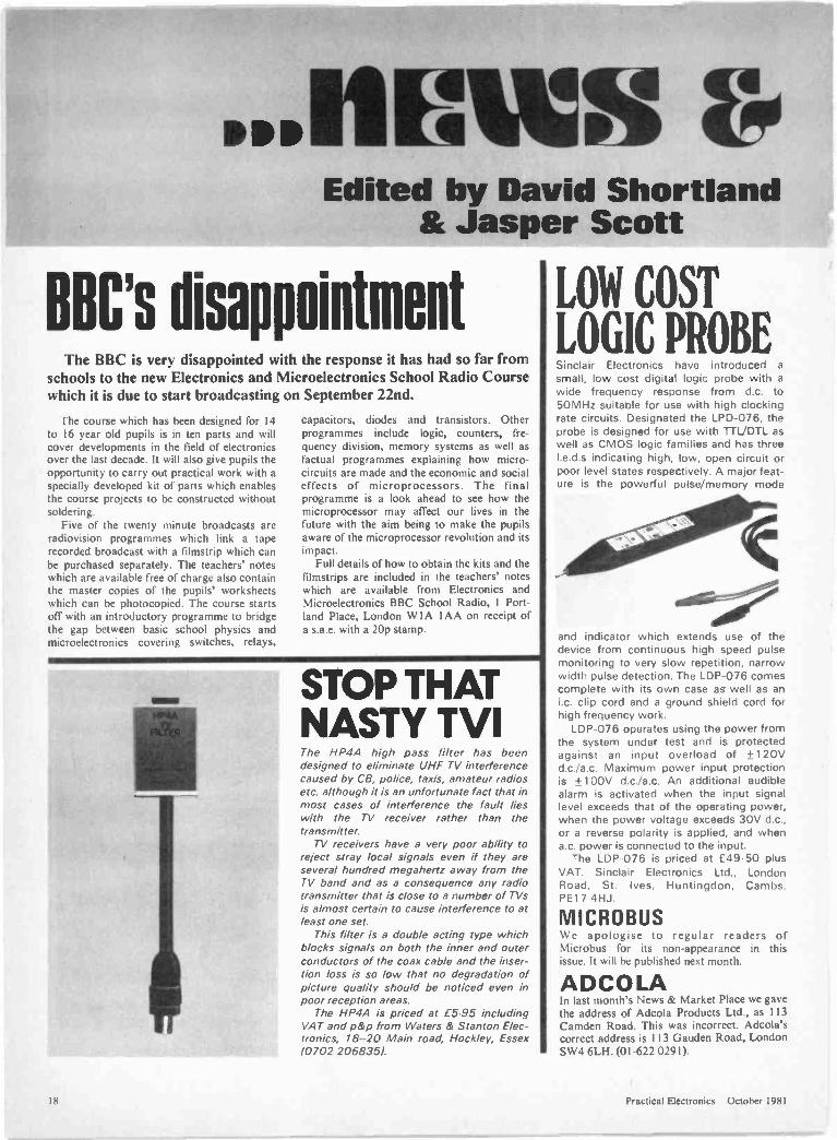
LOW COST
LOGIC PROBESinclair Electronics have introduced a
small, low cost digital logic probe with awide frequency response from d.c. to50MHz suitable for use with high clockingrate circuits. Designated the LPD-076, theprobe is designed for use with TTL/DTL aswell as CMOS logic families and has threeI.e.d.s indicating high, low, open circuit orpoor level states respectively. A major feat-ure is the powerful pulse/memory mode
and indicator which extends use of thedevice from continuous high speed pulsemonitoring to very slow repetition, narrowwidth pulse detection. The LDP -076 comescomplete with its own case as well as ani.c. clip cord and a ground shield cord forhigh frequency work.
LDP -076 operates using the power fromthe system under test and is protectedagainst an input overload of +120Vd.c./a.c. Maximum power input protectionis ±100V d.c./a.c. An additional audiblealarm is activated when the input signallevel exceeds that of the operating power,when the power voltage exceeds 30V d.c.,or a reverse polarity is applied, and whena.c. power is connected to the input.
The LDP -076 is priced at £49.50 plusVAT. Sinclair Electronics Ltd., LondonRoad, St. Ives, Huntingdon, Cambs.PE17 4HJ.
MICROBUSWe apologise to regular readers ofMicrobus for its non-appearance in thisissue. It will he published next month.
ADCOLAIn last month's News & Market Place we gavethe address of Adcola Products Ltd., as 113Camden Road. This was incorrect. Adcola'scorrect address is 113 Gauden Road, LondonSW4 6LH. (01-622 0291).
18 Practical Electronics October 1981
nuuton:PRACIR
The growth in the sale of teletext receiverscontinues with Mullard announcing an orderfrom Thorn Consumer Electronics for120,000 teletext modules worth around £2million. Thorn's are currently producingteletext set at an annual rate approaching aquarter of a million. Watford Electronics have just announced thatthey have been appointed as distributors to theamateur market by Texas Instruments andwill supply the complete range of TIsemiconductors. The first national CB exhibition will take placeat the Royal Horticultural Society's Old Hall,Westminster, London on the II, 12 and 13September. With the legalisation of CB expec-ted during September/October all the equip-ment at the show will become legally availablea few weeks after the exhibition. Anyone with an interest in amateur roboticswill be pleased to hear of 'Transducer'-aclub which specialises in the subject.
The annual membership fee and subscrip-tion to the newsletter is £5. Complete clubmembership can also be arranged. For a sam-ple newsletter and further details readersshould send a cheque or postal order for 50pto D. Stocqueler, 66 Waterloo Road, Penylan,Cardiff Newcastle upon Tyne Education Committeeinform us that they are running a radio courseat Gosforth. beginning in September. Thecourse is designed to prepare students for theRadio Amateurs Examination in May/June1982 and will run at the Gosforth AdultAssociation Classes at Gosforth SecondarySchool. Gosforth. Newcastle upon Tyne.
Although specifically for the R.A.E. thecourse is also ideal for anyone wanting to getan insight into radio theory, having just takenup radio or electronics generally as a hobby orprofessionally. The course will be held onTuesdays of each week from 7pm to 9pm, andcandidates may sit the R.A.E. at the school.
Enquiries should be addressed to: The Prin-cipal. Gosforth Adult Association, GosforthSecondary School, who will forward a
prospectus by return, or further informationcan be obtained by telephoning Newcastleupon Tyne 668439.
Items mentioned are available through nor-mal retail outlets unless otherwise specified.Prices correct at time of going to press.
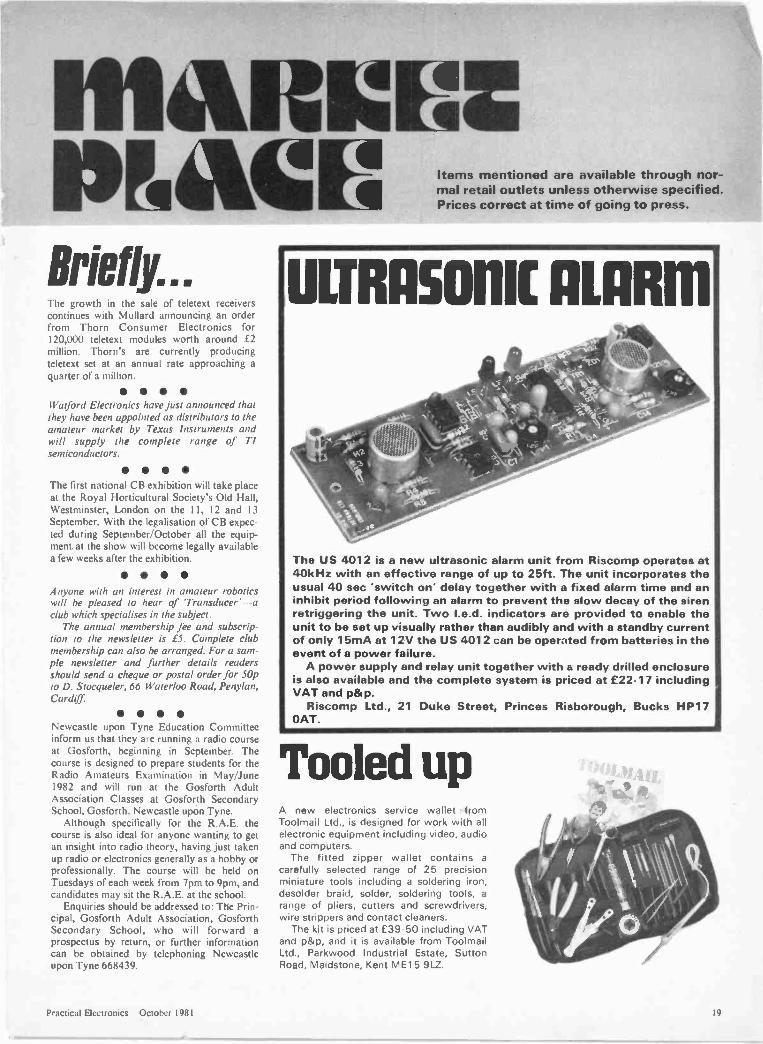
ULTRAMMIC ALARM
The US 4012 is a new ultrasonic alarm unit from Riscomp operates at40kHz with an effective range of up to 25ft. The unit incorporates theusual 40 sec 'switch on' delay together with a fixed alarm time and aninhibit period following an alarm to prevent the slow decay of the sirenretriggering the unit. Two I.e.d. indicators are provided to enable theunit to be set up visually rather than audibly and with a standby currentof only 15mA at 12V the US 4012 can be operated from batteries in theevent of a power failure.
A power supply and relay unit together with a ready drilled enclosureis also available and the complete system is priced at £22.17 includingVAT and p&p.
Riscomp Ltd., 21 Duke Street, Princes Risborough, Bucks HP17OAT.
Tooled upA new electronics service wallet fromToolmail Ltd., is designed for work with allelectronic equipment including video, audioand computers.
The fitted zipper wallet contains acarefully selected range of 25 precisionminiature tools including a soldering iron,desolder braid, solder, soldering tools, a
range of pliers, cutters and screwdrivers,wire strippers and contact cleaners.
The kit is priced at £39.50 including VATand p&p, and it is available from ToolmailLtd., Parkwood Industrial Estate, SuttonRoad, Maidstone, Kent ME 1 5 9LZ.
Practical Electronics October 1981 14

TRAVELLERSCHESS SETVulcan's executive chess set is a hand-heldchess computer which is especially recom-mended by the World Chess Federation fortravelling chess enthusiasts. It has a largeI.c.d. chessboard and black futuristicstyling.
For the first time, a player can move elec-tronic chess pieces across the board as if
a mann= imamthey were real pieces on a conventionalboard, with the novel cursor control system.
Executive chess has 8 levels of play-from beginner to expert- and it can beoperated from mains or battery. It offersmost of the features of non -portablemodels, plays either black or white and iseasily reversible. This model will even playagainst itself.
The price of the Executive is £89.95 in-cluding VAT.
UPGRADED
INBOARDBoss Industrial Mouldings have up-graded their range of Bimboardprototyping systems. The new rangeincorporates either 1, 2, or 3 individualbimboards mounted on a 15 degreesloping front panel with a triple rangepower supply.
Each Bimboard has a central bread-boarding area in which 47 horizontalrows of 5 interconnected sockets areset either side of a central channel on a2.54mm matrix together with integral
Please check dates before setting out, as we cannot guarantee the ac-curacy of the information presented below.
BEX Cardiff Sept. 3-4. Centre Hotel. KBusiness & Light Aviation Sept 3-5. Cranfield Airport. ZMicroprocessor Workshop Sept. 7-8. University of Liverpool. DLaboratory Sept. 8-10. Grosvenor House, Park Lane. London. IPersonal Computer World Show Sept. 10-12. Cunard Hotel, London.MWest of England Electronics Show Sept. 15-17. Bristol ExhibitionCentre. QMicrotest Sept. 21-24. University. Kent. GIBusiness Telecoms & Electronic Office Sept. 23-25. Royal LancasterHotel. London. 0Microtest Sept. 21-24. (Symposium). Kent University. Canterbury. SIBEX Edinburgh Sept. 30 -Oct. I. Assembly Rooms KViewdata Oct. 6-8. Wembley Conference Centre. London. 0BEX Bristol Oct. 14-15. Exhibition Centre. KVideo Show Oct. 16-18. West Centre Hotel, London. ZIThere are Continuous Events & Permanent Exhibition at the NationalMicro & Electronics Centre. LI
DGI
KLI
ZIM
O
QSI
T
20
Liverpool Univ., Brownlow Hill, PO Box 147Sert, 8 Charing Cross Rd.. LondonITF, Solihull `021-705 6707Douglas Temple. Bournemouth 0202-20533World Trade Centre ( 01-488 2400Montbuild Exhibitions f 01-486 1951Online. Northwood. Middx. `09274 28211Exhibitions for Industry 0883 34371SERT `01-403 2351Trident. Tavistock f 0822 4671I PC Exhibitions. Sutton `01-643 8040
bus strips on each side for carryingpower.
The system incorporates a fixed 5Vd.c. . 0.2V) at 1A supply plus indepen-dently adjustable positive and negativerail 5V TO 15V at 0-5A supplies.Each supply is fully isolated and hasshort circuit protection.
The basic Bimboard is priced at £70ex. VAT and p&p with extra boardsavailable for £5.70 ex. VAT.
Boss Industrial Mouldings Ltd., 2Herne Hill Road, London SE24.
Simply place the tool over the ends of d.j.!. 8, 14 or 16 pini.c.s and pull them out-it's that easy now!
Practical Electronics October 1981
0 0
0 It
INDUSTRY
REBOOK
0
Wm.
JobsThe urban disturbances during the sum-
mer inevitably focused attention on theircauses with jobs, or more precisely lack ofthem, as a leading contributor. This may betrue but we shouldn't be surprised at therise in the unemployed.
When we look back to 1974 when theminers' strike toppled the Heath govern-ment, unemployment was 2.6 per cent with585,000 people out of work according tothe register. But was this the true figure?When the nation was forced to operate athree-day working week most firmsachieved figures of upwards of 80 percentof normal output and some, in the excite-ment of the new challenge, were reportedto have produced over 100 per cent of theirnormal weekly output.
It was jokingly observed that perhaps athree-day week could be made permanent.But Labour won the day on the slogan of'getting the nation back to work', at thesame time giving the miners all and morethan they had demanded, thus triggering offbig pay increases all round which led toover 25 percent inflation and ultimately tothe 'winter of discontent'.
The three-day week revealed that in-dustry was over -manned. As wages andinflation soared the crunch became in-evitable. De -manning started seriously un-der Labour who doubled the dole queue,and has accelerated during the Conser-vative drive for greater efficiency. Unem-ployment, previously concealed by over-manning, is now on public view. We are nolonger deceived.
The point is perfectly illustrated byJaguar whose current output of cars ishigher and of better quality than a year agowith 40 per cent fewer employees. And yet,say Jaguar, the company is not yet cost -competitive with comparable manufac-turers on the European mainland.
No politician dare admit it but it has to befaced that what is described as the 'natural'level of unemployment in the UK will settleat a figure in excess of two million even
following a substantial increase in worldtrade which, according to a recent forecastfrom the International Monetary Fund, isunlikely in the immediate future.
In fact the unthinkable, the unspeakable,the politically unacceptable, has actuallyhappened. The meaning of the term full em-ployment has in seven years changed fromhalf -a -mil ion to a new norm of two -million plus on the unemployed register.This would be perfectly supportable withnine people out of ten profitably employedbut for the present uneven distributionamong geographical regions, among ethnicgroups and among age groups.
No political party in a free society is ableto solve the problem. You cannot force peo-ple to move from one area to another, orforce industry to employ unwanted peopleor invest in areas which are regarded astroublesome. The easy option of injection ofyet more public cash into the areas of dif-ficulty is only a short-term palliative.
In the end the individual is forced to lookto his own resources. In this respect theWelfare State, so hopefully instituted morethan 30 years ago, may have done moreharm than good by diminishing personal in-itiative. 'They' will care for everyone, it's'their' fault, etc.
Has the great educational experiment ofrecent years been successful? This shiftedthe emphasis from vocational training (i.e.producing factory and office fodder) to in-struction in life and living with the objectiveof students emerging as well-roundedresponsible citizens equipped to exploit allthe exciting possibilities of increased leisurewhich was bound to come, and seen to becoming, in the age of automation. Oneresult of liberal education is a growing hardcore of youth, illiterate, inarticulate, oftendelinquent, virtually unemployable, yetequally unable to direct their energy toharmless enjoyment. The common excusefor vandalism or worse is boredom.
All, however, is not disaster. The pop-ularity of Practical Electronics and a wholehost of other hobby journals among theyoung is one yardstick of the current levelof intelligent spare -time activity with astrong element of painless self -educationand even career advancement. It isremarkaple how many of the engineeringand technician grades in the electronics andelectrical industries are filled by people whostarted as hobbyists and then realised thata good amateur, literally a lover of the craft,could equally well be a good professional.
My advice to the unemployed young is toget into electronics as quickly as possible.The industry still needs recruits but can af-ford to be selective - in fact has to beselective if it is to continue to ride high inworld markets.
ResultsAll the 'majors' in the industry have now
reported full -year results with GEC, Plessey,Racal and Ferranti all having record years.Thorn -EMI had a profit drop from £125.5million to £94.3 million but even this hic-cup still pleased the City who feared aworse result.
GEC, the traditionally cautious plodder,
upped profits from £415 million to £476million which compares more thanfavourably with British Steel's loss of £668million in the same period. Racal, despitefears that the Decca acquisition was tooexpensive and would be difficult to turnround, upped profits by £22 million to£73.2 million. The Racal-Decca companieswhich account for some 30 per cent oftumover were losing £12 million a year.The loss is now down to £2.5 million andall set for profit next year.
How is it that companies like Racal andGEC continue to prosper through goodtimes and bad, seemingly unaffected by oilshortages or glut, high or low exchangerates, good or bad government? It can onlybe that they have goods or services thatothers want to buy. Without that they arenothing. Now add on leadership, manage-ment, sound economics, market strategyand a willing, if not always enthusiastic,workforce and you get somewhere near thecomplete success package. It is quite truethat big and well established companieshave a momentum of their own but youdon't need to be big to be successful. Thebig companies also had to start small.
One of the year's best success stories isMemory and Electronic Components(MEMEC) started in the 1974 recession byDick Skipworth and his aide Ed Sturmer.They had a single product range to sell, in-tegrated circuits from Harris Semiconduc-tor, and later expanded the range to includeother components and microcomputerequipment. Turnover by 1976 had grownfrom nil to £454,000. Last year it was up tonearly £7.3 million.
When the company went public in Julythe 10p shares were offered at £1.40 each.The issue was oversubscribed 58 times anddealing started at £1.96. As chairman andmanaging director 43 -year -old DickSkipworth draws £55,000 a year salary. Healso owns nearly 4 million shares. Ed Stur-mer, who is 34, is on £40,000 and has overa million shares. Both are now wealthy menthrough providing a service that peoplewanted to buy and they did it during reces-sion. The original 'one -man -and -a -boy' hasexpanded to 73 employees and morepeople are being recruited.
Fight BackAccording to BREMA, UK manufacturers
will capture half the small screen TV marketthis year compared with only one quarterlast year. Fidelity Radio is one companyfighting back with a low priced colour setwith the first 40,000 production alreadysold. The company has taken on 100 moreworkers, over half school leavers.
Another fight -back factory is atBridgnorth where the former Decca TV fac-to -y is now under the Taiwanese manage-ment of Tatung (UK). Employees there arehappy with a new tougher disciplinary codeeased by a courtesy from managementpreviously unknown in the area. The unionslike it, too. Of the 580 workforce only 40are reported to have taken redundancyrather than work in newly imposed condi-tions. The remainder have welcomed thenew regime.
Practical Electronics October 1981 21

'. : .
HOROLOGICStar Clock J. S. B. Dick
S°CRATE:S. itthe soul. Certainty, ?
those crisp frosty nights, with a Myriad of -.stars twinkling ,
gent y, is a beautiful sight. As the space-age progi-esses,many people have become interested in astronomy as ahobby; the mystery of infinite space, the spectacular objectsto be seen, and the ever-changing planets all exert an attrac-tion to the star -gazer.
The stars, as seen from Earth, appear to be fixed to acelestial sphere which revolves continuously. The apparentposition of any particular object changes throughout thenight, but all is not chaos, however. The stars on theircelestial sphere have, over the centuries, been mapped-just as the earthly sphere has been --with an astronomicalequivalent of latitude and longitude. Knowing the celestialco-ordinates of any object and a quantity called "LocalSidereal Time" enables the astronomer to find any object inthe sky and train a telescope on it.
This article describes a simple, dual -system clockdesigned to indicate both Greenwich Mean Time and LocalSidereal Time. Small physical size, low power consumptionand ease of use permit the clock to be used out of doors-even, perhaps, at a remote observing site chosen for darkskies.
THE HEAVENLY CLOCKWORK PROBLEMWhy does the astronomer require this quantity called
sidereal time? Sidereal time (time of the stars) has years,days, hours, etc., like mean time. One mean -time day, orsolar day, is the time taken by the Earth to revolve until thesun re -occupies a set position in the sky; the sun is thoughtof as being due south each day at noon, for example. Asidereal day is the time taken until a star re -occupies a setposition in the sky; it is shorter than the solar day, the effectessentially being caused by the motion of the Earth in itsorbit. In units of mean time, the sidereal day is 23 hours 56minutes 4 seconds long. Alternatively, there are 24 hours 3minutes 56 seconds of sidereal time in a solar day.
This sounds rather baffling, but simply means if you ob-serve a star at the same time on two nights, on the second
so some 4 minutes earlier. The inequality causes sideretime to move ahead of solar time; the determination of astars position requires sidereal time to be calculated ---afairly lengthy procedure ---or obtained from a special clocklike the unit desc-ibed here.
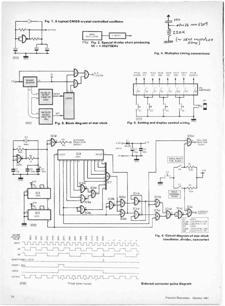
The non-standard rate may he obtained by using a crystaloscillator with a custom -cut crystal or by dividing the outputfrom a frequency -standard crystal (1.0MHz say) by anappropriate value to obtain 1 002738Hz instead of1.000000Hz. A custom -cut crystal might cost £10 with aseven week delivery time and would require a high resolu-tion frequency counter to trim to the correct frequency. Along divider chain with output decoding would employ manyintegrated circuits. Using CMOS devices a maximum crystalfrequency of 5.0MHz could be used to give a conversionaccuracy (mean to sidereal rate) of one part in one million.These methods a -e shown schematically in Figs. 1 and 2.
The HOROLOGICUM uses neither; a novel, incrementalcorrector is employed. With only six integrated circuits atime -averaged ccnversion accuracy of one part in ten millionis obtained. Following a mathematical trend of thought, ifany incoming frequency is divided by 1461 and, when a"carry" occurs, fcur extra pulses are injected into the originalfrequency, the output frequency, f1, is (where fc, is theoriginal frequency):
f, (1 +1461) x fc, 1.002738 fc,
). . . which is the ratio required to obtain sidereal time frommean time. Hence, the problem has been elegantly solved.The block diagram of the design is shown in Fig. 3.
CIRCUIT DESCRIPTIONThe circuit diagram of the star clock is shown in Fig. 6.
The system oscil ator is crystal controlled and operates ata frequency of 1 NOM Hz --well within the capabilities ofCMOS devices. The crystal is driven by a NAND gate (ICd)wired as an inverter. The padding capaci or, C8, is chosen togive a useful range with the trimmer. A heterodyne techni-
usLiliator ar.furateiy id,,0:etnetiVelV;!4 equenc'y coiinter may be g
einPloyed. If greater accuracy s required, the crystal colt.be housed in an oven to rnaintan constant temperature. Thiswas not implemented here because of the low power con-sumption requirement. Two 4518 dual BCD decade coun-ters divide the 1-0MHz signal to 100Hz (=2f0). A further4518 may be added to give one -second markers for an ex-ternal circuit; a socket position has been left available on thep-inted circuit hoard design.
The binary counter, shown in Fig. 3, receives the 100Hzsignal; the device is the CMOS 4040 12 -bit counter (IC8).Outputs Q2, Q6, Q7, Q9, Q10 and Q12 go to six inputs ofthe 4068 (IC7) eight input AND gate. Q8, Q11,03, Q5 and01 are tested for the ALL -ZERO condition by IC9a, c, d,IC6d, and IC7. At a count of 2914, IC6a sets the latch (IC4a,bI 10 1,0-0) and 2f0 is now routed through IC5a, IC4c,d After eight counts (four extra plus four normal) IC8reaches 2922 and IC6b resets IC8 and the latch (Q 0, Q-1). f0 is now routed through IC5b, IC4c, d.
IC5c, d enable the outputs to be held, performing one ofthe setting functions of the clock.
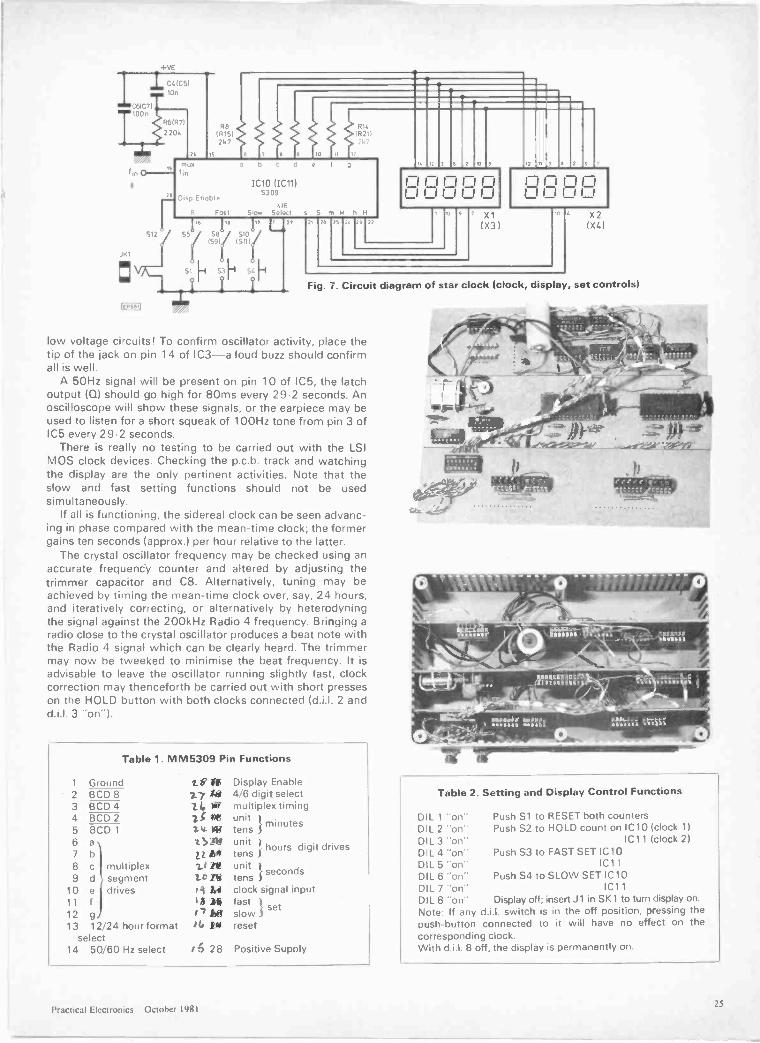
The clock decoding is provided by an LSI chip, theMM5309. This is a general purpose MOS digital clock chipwith (4 or 6 digit) drive capabilities compatible with theminiature displays used: Hewlett-Packard 5082-7405 and-7402 ("W" brightness class) devices. Display luminosity isequivalent to the average I.e.d. calculator and is certainlyadequate in the astronomical environment! The MM5309pin functions are shown in Table 1; selection pins left uncon-rected float to +ve voltage because of internal pull-upresistors. Six digit, 24 -hour mode and 50Hz input are selec-ted; the multiplex timing connections are shown in Fig. 4.The setting and display circuit is shown in Fig. 5 with func-t on description in Table 2. At first reading, this method ofsetting may seem rather inefficient. However, it renders theExterior fitted push -buttons immune from accidentalmanipulation, an important criterion for portable equipmentof this type.
To achieve the dual time option, two clocks are used
\carted output (to x 1-002738)
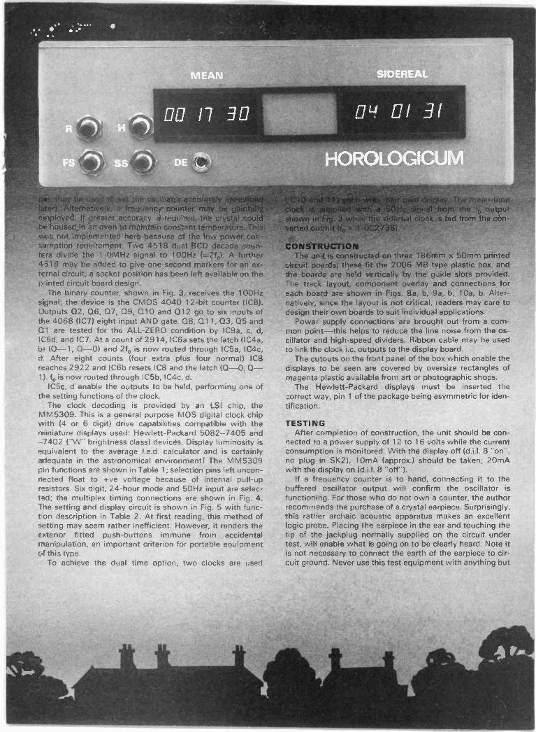
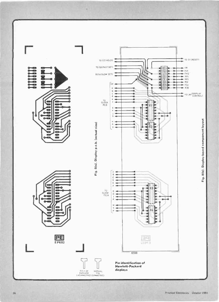
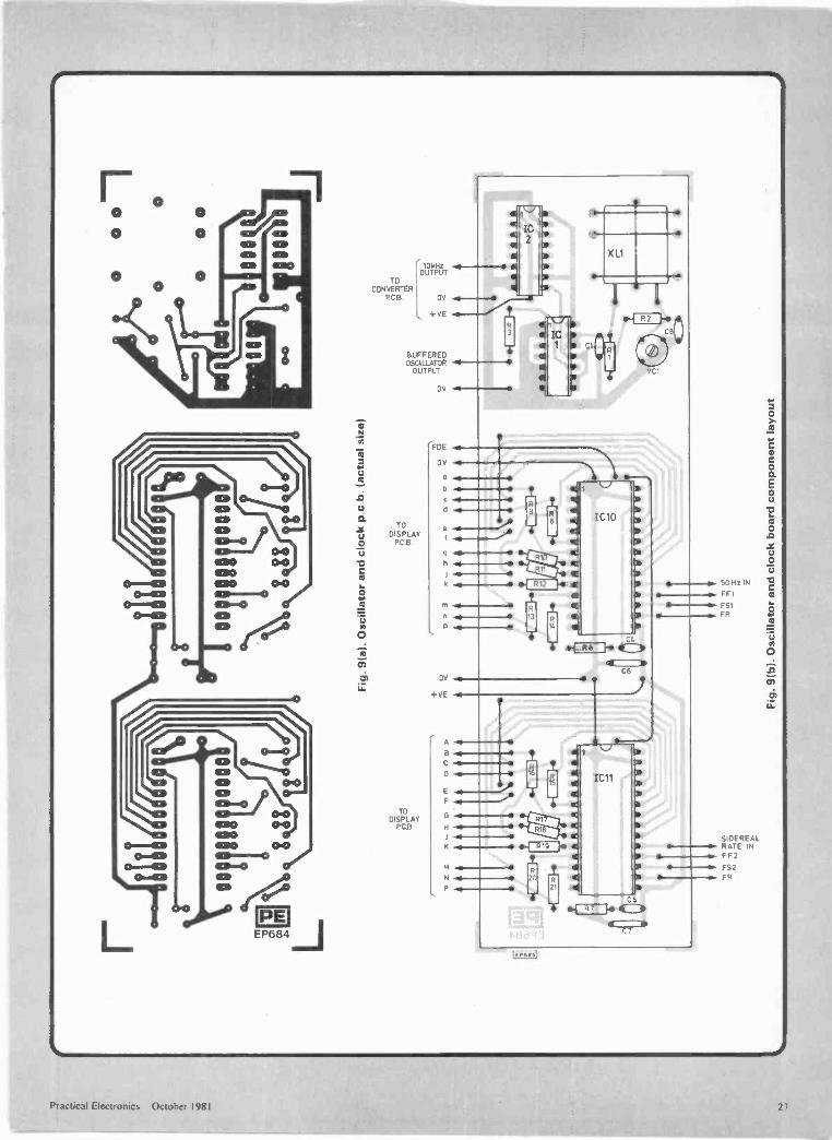
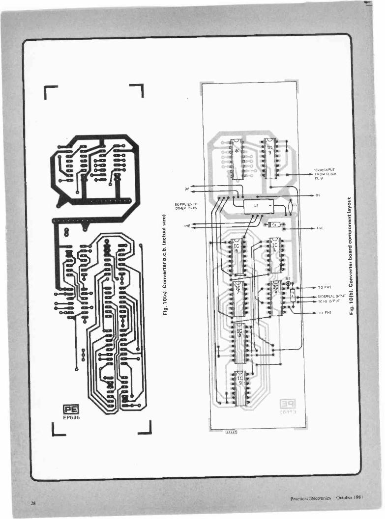
CONSTRUCTIONThe unit is constructed on three 186mm x 50mm printed
circuit boards; these fit the 2006 MB type plastic box, andthe boards a"e held vertically by the glide slots provided.-he track layout, comoonent overlay and connections foreach board are shown in Figs. 8a, b, 9a, b, 10a, b. Alter-natively, since the layout is not critical, readers may care todesign their own boards to suit individual applications.
Power supply connections are brought out from a com-mon point --this helps to reduce the line noise from the os-cillator and high-speed dividers. Ribbon cable may he usedto link the clock i.c. outputs to the display board.
The cutouts on the front panel of the box which enable thedisplays to be seen are covered by oversize rectangles of-nagenta plastic available from art or photographic shops.
The Hewlett-Packard displays must be inserted thecorrect way, pin 1 of the package being asymmetric for iden-tification.
TESTINGAfter completion of construction, the unit should be con-
iected to a power supply of 12 to 16 volts while the currentconsumption is monitored. With the display off (d.i.l. 8 "on",no plug in SK2), 1 Orr A (approx.) should be taken; 20mAwith the display on (d.i.l. 8 "off").
If a frequency courter is to hand, connecting it to thebuffered oscillator output will confirm the oscillator isfunctioning. For those who do not own a counter, the authorrecommends the purchase of a crystal earpiece. Surprisingly,this rather archaic acoustic apparatus makes an excellentlogic probe. Placing the earpiece in the ear and touching thetip of the jackplug ncrmally supplied on the circuit undertest, will enable what is going on to be clearly heard. Note itis not necessary to connect the earth of the earpiece to cir-cuit ground. Never use this test equipment with anything but
rEP6751
2 to
RI
IC1c
- ClT "P
Q Fig. 1. A typical CMOS crystal -controlled oscillator
XL1
'III1MHz
OUTPUT
T T
C8 044.VCITloop 50p
15
+VE
T712
IC24518
+VP
io 2 MIIC3
4518
5MHz HOSCILLATOR
UZI
99727 HFig. 2. Special divider chain producing50 x 1.002738Hz
Jon
1-40,4 24 NM 6.109
(-s/ 1 K,I2 muerikeyA4 --re)
Fig. 4. Multiplex timing connections
to X PIN16 PINS PIN13 PIN18 PIN18 PM 17 PIN17 PIN281002738 ICs101111 ICS ICS 1C10 1C11 1C10 1C11 ICs101211
Fig. 3. Block diagram of star clock
BUFFEREDOSCILLATOROUTPUT
dCLOCK IC84040
R SET
9 3 13 tS 11
9
IC7
IC9b
INPUT
OV
aama
Fig. 5. Setting and display control wiring
DI+ VP+1250
11011
11.14001C2 C3
100u TOOn
IC6a
IC6 b
IC4 b
IC4 a
BINARYCOUNTER
VALUEnO1, ry
01 0,1,1
01 0, 01 01111
INPUT
01
02
RESET/COUNT. 292211
COUNT . 29141
LATCH
OUTPUT
*FOUR EXTRA PULSES
I
IC5b
IC5a
HOLD MEANTIME CLOCK
52
IC5 d
OILSWITCHES
50Hz FORMEAN TIME
CLOCK
84
56°"4jW%-'100k +VE
57
HOLDSIDEREAL
CLOCK
119J
R5
o-do-NA/14-.100k
SIDEREALOUTPUT
ICI .40111C4&9.4001 PIN14.+VE10566 . 4081 PIN 7. OV1C7 . 40681C283 . 45181 PIN16.+VE1C8 .4040) PIN 8 . OV
Fig. 6. Circuit diagram of star clock(oscillator, divider, converter)
Sidereal corrector pulse diagram
24 Practical Electronics October 1981
,b N7i220k
26
R867151 4t2112k7 2k7
15 10 11
28
muxtln
[lisp Enable4/6
R Fast Slow Select s S m M 0 H
a b c d e I
IC10 (IC11)5309
In 20 1 22
2
n nLi! i_uu n )CLIU II I
11
127 X1
1X3'X2
(X4)
Fig. 7. Circuit diagram of star clock (clock, display, set controls)
low voltage circuits! To confirm oscillator activity, place thetip of the jack on pin 14 of IC3-a loud buzz should confirmall is well.
A 50Hz signal will be present on pin 10 of IC5, the latchoutput (Q) should go high for 80ms every 29.2 seconds. Anoscilloscope will show these signals, or the earpiece may beused to listen for a short squeak of 100Hz tone from pin 3 ofIC5 every 29.2 seconds.
There is really no testing to be carried out with the LSIMOS clock devices. Checking the p.c.b. track and watchingthe display are the only pertinent activities. Note that theslow and fast setting functions should not be usedsimultaneously.
If all is functioning, the sidereal clock can be seen advanc-ing in phase compared with the mean -time clock; the formergains ten seconds (approx.) per hour relative to the latter.
The crystal oscillator frequency may be checked using anaccurate frequendy counter and altered by adjusting thetrimmer capacitor and C8. Alternatively, tuning may beachieved by timing the mean -time clock over, say, 24 hours,and iteratively correcting, or alternatively by heterodyningthe signal against the 200kHz Radio 4 frequency. Bringing aradio close to the crystal oscillator produces a beat note withthe Radio 4 signal which can be clearly heard. The trimmermay now be tweeked to minimise the beat frequency. It isadvisable to leave the oscillator running slightly fast, clockcorrection may thenceforth be carried out with short presseson the HOLD button with both clocks connected (d.i.l. 2 andd.i.l. 3 "on").
Table 1. MM5309 Pin Functions
1
2
3
4
Ground 2112714811. w2S Mg
BCD 8BCD 4BCD 2
5 BCD 1 2.41. vg
6 a 2}2,47 b Z2.1648 c multiplex IA at9 d segment Lc lb
10 e drives #4 $411 f la /1112 g #1 he13 1 2/2 4 hour format
select14 50/60 Hz select
Display Enable4/6 digit selectmultiplex timingunit )
minutes
unit ) hours digit drivestens 1unit )
seconds
clock signal inputfast k setslow 1reset
/6 28 Positive Supply
MN,
Table 2. Setting and Display Control Functions
DIL 1 "on" Push S1 to RESET both countersDIL 2 "on" Push S2 to HOLD count on IC10 (clock 1)DIL 3 "on- ICI 1 (clock 2)D L 4 "on" Push S3 to FAST SET IC10DIL 5 "on- ICI 1DIL 6 -on" Push S4 to SLOW SET IC10DIL 7 "on" IC11DIL 8 "on" Display off; insert J1 in SK 1 to turn display on.Note: If any d.i.l. switch is in the off position, pressing thepush-button connected to it will have no effect on thecorresponding clock.With d.i.l. 8 off, the display is permanently on.
Practical Electronics October 198125
PEE P682
L
TO 52 (HOLD)
TO S31 FAST SETT
TO 54ISLOW SET I
TOCLOCK
PCB.
TO
CLOCKPC. B
L,J
PIN1 OF NORMALPACKAGE PIN
I ASYMMETRIC) (SYMMETRIC)
OS -4-*o ..11.10
h
A
F
C
K
N
P
-0 SIIRESETI
FR
FH1
FH2
FF1
FF2
FS1
F52
FOE
61,
Pin identification ofHewlett-Packarddisplays
To imIDISPLAYCONTROL
26 Practical Electronics October 1981
17-0
4111
1n1
x,88
88
som
nfro
osso
rgT
000
g88
8 88
0
0 ca
m I
+
st'I I
I
-i*A
AA
AA
AA
at<
dO
ww
ww
ww
w
Fig
. 9(a
). O
scill
ator
and
clo
ck p
c h
. (ac
tual
siz
e)
Inso
V.
11,1
11ir
To
0
CDvo
F,
0
Fig
. 9(b
). O
scill
ator
and
clo
ck b
oard
com
pone
nt la
yout
O0
O1
O
O0
0
g
Cl0
02 C
gdr\
ii\\,2
,r"
?ol" F
ig. 1
0(a)
. Con
vert
er p
.c.b
. (ac
tual
siz
e)
Fig
. 10(
b). C
onve
rter
boa
rd c
ompo
nent
layo
ut
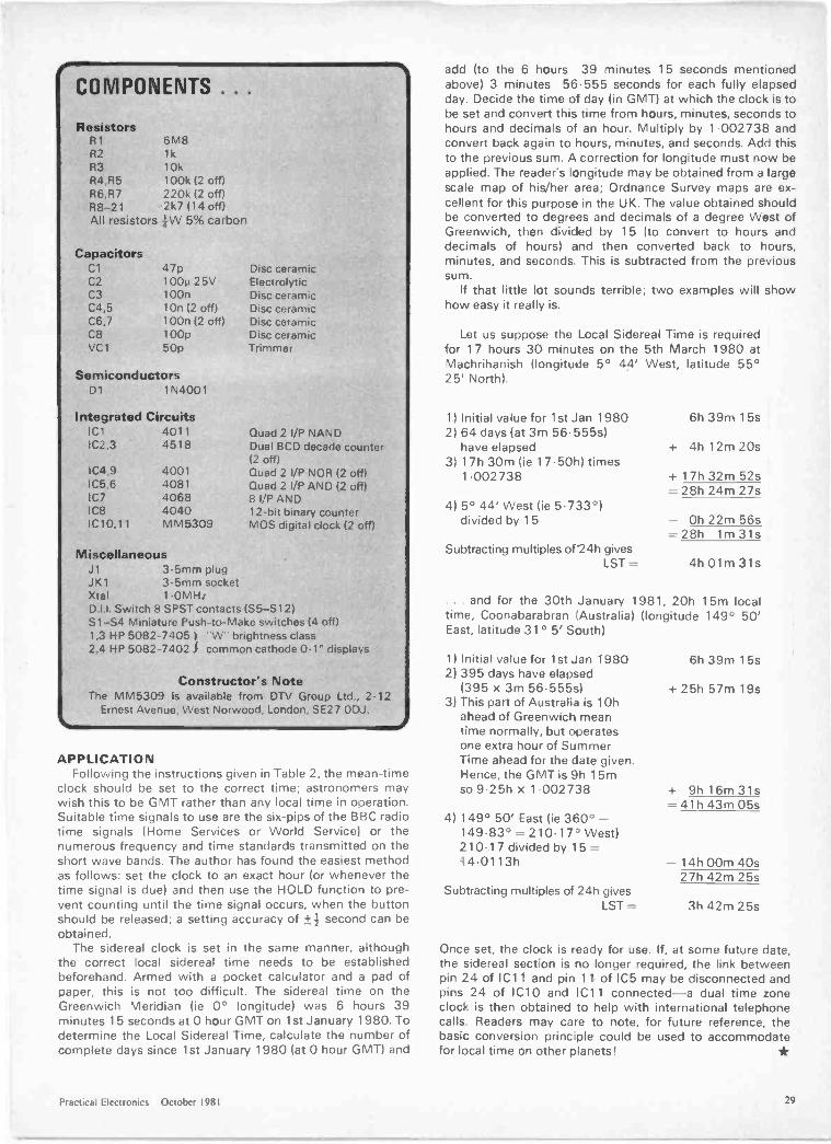
COMPONENTS . . .
ResistorsR1
R2R3R4.R5
6M81k
10k100k 12 off)
R6.R7 220k (2 off)R8-21 2k7114 off)All resistors iW 5% carbon
CapacitorsC1 47p Disc ceramicC2 100p 25V ElectrolyticC3 100n Disc ceramicC4,5 10n (2 off) Disc ceramicC6,7 100n (2 off) Disc ceramicC8 100p Disc ceramicVC1 50p Trimmer
SemiconductorsDt 1N4001
Integrated CircuitsICI 4011IC2,3 4518
Quad 2 I/P NANDDual BCD decade counter(2 off)
IC4,9 4001 Quad 21/13 NOR (2 off)IC5,6 4081 Quad 2 I/P AND (2 off)IC7 4068 8 I/P ANDIC8 4040 12 -bit binary counterIC10,11 MM5309 MOS digital clock (2 off)
MiscellaneousJ1 3.5mm plugJK1 3.5mm socketXtal 1.0MHzD.i.l. Switch 8 SPST contacts (S5 -S12)S1 -S4 Miniature Push -to -Make switches (4 off)1,3 HP 5082-7405 i "W" brightness class2,4 HP 5082-7402 common cathode 0.1" displays
Constructor's NoteThe MM5309 is available from DTV Group Ltd., 2-12
Ernest Avenue, West Norwood, London, SE27 ODJ.
APPLICATIONFollowing the instructions given in Table 2, the mean -time
clock should be set to the correct time; astronomers maywish this to be GMT rather than any local time in operation.Suitable time signals to use are the six -pips of the BBC radiotime signals (Home Services or World Service: or thenumerous frequency and time standards transmitted on theshort wave bands. The author has found the easiest methodas follows: set the clock to an exact hour (or whenever thetime signal is due) and then use the HOLD function to pre-vent counting until the time signal occurs, when the buttonshould be released; a setting accuracy of +4- second can beobtained.
The sidereal clock is set in the same manner, althoughthe correct local sidereal time needs to be establishedbeforehand. Armed with a pocket calculator and a pad ofpaper, this is not too difficult. The sidereal time on theGreenwich Meridian (ie 0° longitude) was 6 hours 39minutes 15 seconds at 0 hour GMT on 1st January 1980. Todetermine the Local Sidereal Time, calculate the number ofcomplete days since 1st January 1980 (at 0 hour GMT) and
add (to the 6 hours 39 minutes 15 seconds mentionedabove) 3 minutes 56.555 seconds for each fully elapsedday. Decide the time of day (in GMT) at which the clock is tobe set and convert this time from hours, minutes, seconds tohours and decimals of an hour. Multiply by 1.002738 andconvert back again to hours, minutes, and seconds. Add thisto the previous sum. A correction for longitude must now beapplied. The reader's longitude may be obtained from a largescale map of his/her area; Ordnance Survey maps are ex-cellent for this purpose in the UK. The value obtained shouldbe converted to degrees and decimals of a degree West ofGreenwich, then divided by 15 (to convert to hours anddecimals of hours) and then converted back to hours,minutes, and seconds. This is subtracted from the previoussum.
If that little lot sounds terrible; two examples will showhow easy it really is.
Let us suppose the Local Sidereal Time is requiredfor 17 hours 30 minutes on the 5th March 1980 atMachrihanish (longitude 5° 44' West, latitude 55°25' North).
1) Initial value for 1st Jan 1980 6h 39m 15s2) 64 days (at 3m 56.555s)
have elapsed + 4h 12m 20s3) 17h 30m (ie 17.50h) times
1.002738 + 17h 32m 52s= 28h 24m 27s
4) 5° 44' West lie 5.733°)divided by 15 - Oh 22m 56s
=28h 1m 31sSubtracting multiples of 24h gives
LST = 4h 01m 31s
. . . and for the 30th January 1981, 20h 15m localtime, Coonabarabran (Australia) (longitude 149° 50'East, latitude 31 ° 5' South)
1) Initial value for 1st Jan 19802) 395 days have elapsed
(395 x 3m 56.555s)3) This part of Australia is 10h
ahead of Greenwich meantime normally, but operatesone extra hour of SummerTime ahead for the date given.Hence, the GMT is 9h 15mso 9.25h x 1.002738
4) 149° 50' East lie 360° -149.83° = 210.17' West)210.17 divided by 15 =14.01 13h
6h 39m 1 5s
+ 25h 57m 19s
+ 9h 16m 31s= 41h 43m 05s
- 14h 00m 40s27h 42m 25s
Subtracting multiples of 24h givesLST = 3h 42m 25s
Once set, the clock is ready for use. If, at some future date,the sidereal section is no longer required, the link betweenpin 24 of IC11 and pin 11 of IC5 may be disconnected andpins 24 of IC10 and IC11 connected-a dual time zoneclock is then obtained to help with international telephonecalls Readers may care to note, for future reference, thebasic conversion princ ple could be used to accommodatefor local time on other planets!
Practical Electronics October 1981 29

Introduction toROBOTICS
Professor Wilfrid Heginbotham O.B.E. D.Sc.DIRECTOR GENERAL PRODUCTION ENGINEERING RESEARCH ASSOCIATION (PERA)
I NDUSTRIAL robots have little resemblance to the futuristicmachines of science fiction. But there is one similarity. Most
robots are designed to replace human workers and are built tothe same scale, although they can generally lift much heavierweights and for longer periods. Apart from this superficiallikeness. robots are very different from either humans or therobots of science fiction. They are really little more thanmachine tools, whose prime function is the handling of compo-nents. To carry out this task most robots have one manipulativearm which provides either point-to-point motion or a continuouspath. The "architecture" of a robot may be cylindrical or polar,or it may consist of an arm and an elbow.
CAPABILITIESAlthough at first sight an industrial robot can appear almost
humanoid in its capabilities, the resemblance is a delusion. Thefacts fall better into place if one perceives the robot more as an"automated crane" controlled by an electronic cam system. Itsmost versatile feature is its ability to be re -programmed so thatits arm obeys a different set of space/time co-ordinates. Onceprogrammed. the machine reverts to being a mechanistic pieceof automation that will perform a sequence of events.
Robots are good at mimicking the space/time co-ordinationskills of a manual operator. For instance, one could record themovements of the conductor of an orchestra in such a way that,on future occasions, the robot would faithfully conduct theorchestra in precisely the same way as the conductor had done.It would, however, be completely unaware if the first violin wereabsent or. indeed, whether or not the entire orchestra were thereat all. One could prepare for such hazards by equipping eachseat with a sensor to detect the presence of players and so inhibitthe robot motion until all were present; but even then the robotcould be fooled by a "non -player" sitting in the chair. This sim-ple example completely describes the present extent of robot in-telligence and prevents one from expecting too much.
The full potential for robot versatility within a particular fieldof activity depends on how that activity fits the robot architec-ture and technology. Robots are ideal:a. For the tracing of curves, where a low level of accuracy is
sufficient.b. Where no gripping is necessary, or where a loose grip is suf-
ficient.c. Where a standard no -variable gripping surface exists
naturally on the component (ie, in die casting).d. Where the skill of the manual operator is restricted to judge-
ments within a clearly defined space/time pattern.e. On relatively dedicated precision applications when suf-
ficient peripheral "tooling" can "clean up" the final compo-nent position to the required accuracies.
/
41;10
These operations can be classed into four different categories,each with its own characteristics. They are listed below, with ex-amples of typical operations.
QUICK AND EASILY CHANGEDThe first category includes spray painting, shot peening, spot
welding, stud welding, flame cutting, the application of gasketsealing compounds, coating, marking, heat sealing, glass cutting,water jet cleaning, drilling and any routine where no gripping isrequired. In these situations, so long as suitable means areavailable to initiate the process (ie, one single time/space co-ordinate to relate the start of the component/robot timerelationship) then the job can be changed in a matter of minutes.Some robots can store a multiplicity of pre-recordedprogrammes.
The second category concerns operations where the grippingneed not be very precise or where standard gripping surfaces areavailable (ie, gripping surfaces on the component or standardjob holders). It includes the unloading of die casting and injec-tion moulding machines, the dipping, quenching and handling ofinvestment castings, unloading presses, unloading furnaces, flatsheet transfer, brick handling and stacking, heat treatment,rough transfer operations, stacking pallets and sacks and thegeneral loading and unloading of machine tools over a range ofcylindrical or other regular prismatic workpieces.
The third category demands more precise operations. In-terstage tooling and special grippers and/or fixtures may benecessary for each different situation. Examples are the transferbetween stations for hot and cold forging operations, the loadingand unloading of machine tools in general work, inspectionprobing, filament winding, wire wrapping, sprue cutting, sortingand packing, deburring, fettling, drilling, routing and arcwelding. The needs of any particular operation will need to becarefully scrutinised in order to select the appropriate activities.
The fourth category includes the control of assembly andparts in a factory where variability levels are high.
An analysis of 600 typical robot installations in the UK andWest Germany showed that the proportion of activities in thevarious categories are:
UK 1981(BRA)
West Germany 1980(IPA)
Category 1 36.0% 45.0%Category 2 48.0% 42.0%Category 3 15.0% 12.5%Category 4 1.0% 0.5%
30 Practical Electronics October 1981

These interesting samples reflect very well the areas of ac-tivity where industrial robots of the present generation areeasiest and most profitable to apply. The pattern does not seemto be significantly altered by differences in the two countries'economies.
From experience, it is possible to distil a few principles thatdetermine the viability of robots in particular circumstances:
a. The skills required for the particular job:- sight- touch- hearing
b. The extent to which the pattern and need for these skills isrepeated without ambiguity.
c. The "peripheral" controls required to ensure an adequatecontrol of incoming material for:
- position- quality- variability
d. The need for the human workforce to carry out inspectiontasks as part of the operation.
e. Safety and "guarding" requirements.The suitability of a robot for light handling depends upon the
speed of the operation. It is generally difficult for a robot to keepup with a human operator because human responses are somuch faster. In some machine operations, like forging, humanoperators can alter their scenario and cope with variable eventson the periphery of the machine. But most current robots aregenerally incapable of reacting in this way. This kind of selfprogramming will be the next stage of robot development.
These economic factors can be overruled by other factors. Abad working environment can be a powerful motivating factor inthe decision to use robots instead of people. Indeed it is clearthat many industrial robots are presently used in a relatively un-coordinated way. in a piecemeal fashion. It is apparent that forsome time to come factories will have to adopt a hybrid ap-proach to robots and introduce only partial automation.
THE MINI METROSafety is an important issue. It is important not to try to mix
human work with any part of the possible working universe ofindustrial robots. There is a particular danger if a robot is handl-ing dangerous materials. Some robots are used to pour hot metalinto a die-casting machine or a mould. Any malfunction of therobot system might lead to a scattering of this dangerous
One of the two synchronised welding lines for the Metro
material in areas occupied by humans. This danger should notbe exaggerated. There are several successful installations ofteams of robots performing relatively simple operations. In thenew Mini Metro line two lines each of 14 unimates are used tospot weld car body shells.'
To get the best out of a robot in applications where theprocess cycle times are relatively long, it is desirable to allow therobot to service several machines placed within its reach, and tocarry out auxiliary functions like inspection. For example, a Cin-cinnati T, industrial robot can serve two turning centres and aninspection station.' The inspection station uses a laser tomeasure the size of components and the robot can extract a partfrom any machine and pass it through the inspection systembefore accepting it as a correct component.
The fully versatile small batch automatic factory will only beachieved when robots have sufficient "intelligence" to deal withincreasing levels of variability in their environmental conditions.Current trends are exemplified by the software control system ofthe Cincinnati T3. It involves three distinct types of branching.The first is conditional branching in which several workplace"states" are monitored and the robot will not continue with itsoperations unless the signals received from the transducers are"green". The second type, offset branching, involves the con-struction of a repertoire of pre -taught sub -routines which formcommon parts of repetitive activities. The continuous need toprogramme these repetitive activities could be tedious and timewasting for the programmer. In the third kind, "interrupt" offsetbranching. pre-recorded routines are selected to deal with con-tingencies which may occur during the robot's automatic cycleof operations. For instance, a failure to insert a part at somepoint of the function would be noted by the robot which woulddivert that part to a scrap bin, initiate the re -selection of anotherpart at the pick-up position, rejoin the sequence and try again tocomplete the function.
A ROBOT BLACKSMITHA more advanced application of this technique is the develop-
ment of a robot "blacksmith". For this particular application, itis essential to understand the process by which metal is defor-med so that it can be represented by suitable algorithms in thecomputational software.' 4 The process is called "open die forg-ing". The robot seeks to form a shape by manipulating thesqueeze anvils of simple prismatic tools in a hydraulic press. Arobot could be taught to complete the process of changing ashape by using the direct skill of a human operator, but usually
A Cincinnati T' serving two turning centres and an inspec-tion station
Practical Electronics October 198I 31

this method takes a long time and very often takes longer thanthe time required to complete the whole batch. It is also a ratherinefficient way of using a robot's computational facilities. It isbetter to develop blocks of programming incorporating theknown characteristics of the process, so that changes in thenumber of steps and the size of steps can be initiated by insertingthe appropriate numerical data. For instance, square -to -squareand square -to -round reduction can be achieved by the routineinsertion of data on the initial and final sizes required by theoperator.
So far, we have assumed that a robot can complete its cyclewithout ambiguity. However, the variations in steel's charac-teristics and possibly temperature can necessitate a continuousfeedback of information on the pressure and position of the anviland the temperature of the billet. The robot could interpret thepossibility of success within an envelope defined by certaincritical values of these parameters so that it could take ap-propriate action. If the temperature falls below a prescribedminimum, for example, the robot would withdraw the billet fromthe forging press and insert it in a re -heating station and releaseit, all the time remembering at what step it had left off theprocess before re -heating. Next, it would continue to forgeanother billet. Then it would pick up the partly finished, re-heated billet, rejoin the sequence and take the forging process toa successful conclusion. This routine is a valid alternative to thehuman's use of sight and touch. A machine's ability to see andfeel is important, of course, but it is better in many cases to seekmachine solutions to problems where the technology availablecan conveniently solve the technological problem.
ASSEMBLY BY ROBOTThe number of robots involved in small batch assembly is
actually very small. Assembly is a highly skilled operation andimplies levels of sensory interaction and mechanical dexteritywhich are not easy to achieve in an economic way. The Unima-tion PUMA Assembly Robot and the DEA Pragma AssemblyRobot are the nearest we have to a general industrial applica-tions The PUMA incorporates another example of "branchingoff -set" technology and can be easily programmed to performmanipulative functions. One of the available sub -routines allows
PE RA PADDS automated draughting system
the device to execute a "pick and place" movement between twopre -selected points in its universe without each successive stephaving to be programmed. As with many other first generationdevices, it is likely to be most adaptable in hybrid situationswhere the people conduct operations that demand a high level ofcybernetic reaction and the robots perform the more mundanetasks.
The next step is the addition of facilities for artificial visionand an artificial sense of touch. These benefits over the nextdecade will be part of a cascade of development leading to moreassembly processes being taken over in their entirety by roboticdevices. These developments will be achieved by a process ofevolution rather than single dramatic leaps in technology.
The wider implications for automated small batch factories ofthe future have yet to be really considered. The possibilities af-forded by the micro -computer make it easier for machines to"communicate" easily with machines and eventually we shallhave to proceed from the present piecemeal applications to anoverall systems approach. At this stage we will have, or a com-puter will have, overall control of design and production func-tions. The situation was adequately expressed by Lord Kelvinwho said, in 1880, "I often say that when you can measure whatyou are speaking about and express it in numbers, you knowsomething about it; but when you cannot measure it, when youcannot express it in numbers, your knowledge is of a meagre andunsatisfactory kind; it may be the beginning of knowledge, butyou have scarcely, in your thoughts, advanced to the stage ofscience, whatever the matter may be".
An example of an automated draughting machine controlledby a minicomputer is the PADDS system developed by PERA.Systems like the PADDS produce detailed drawings withoutdrudgery. The operator uses a keyboard to enter the dimensionsand shapes of the part. according to a simple code, and alsospecifies the reference co-ordinates of the dimensions. The com-puter needs no more information for the "dimensioning" of thecomponent. As it works it will decide whether a drawing withonly two "views" might lead to ambiguity in the specification ofcomponents. and produce extra drawings as required. It is arelatively small step from PADDS to the development ofprogrammes for the numerical control of machine tools.
THE ECONOMIC EFFECTSThe use of robots will increasingly influence, if it does not
already, national economic and sociological development. Theeconomic issues range from the level of employment to the levelof investment. An indication of these parameters in the UK,USA. Japan and West Germany since 1970 is illustrated in Fig.1, which shows the ratio between the hourly earnings index andthe consumer price index. It represents what can be bought withwhat is earned. The performances of Japan and West Germany,particularly after 1974, are remarkable. It is notable that bothcountries have made considerable progress in applying advan-ced methods of automation, and that Japan has as many as halfthe total world population of industrial robots. One could betempted to draw a wrong conclusion from these statistics and itmust be made quite clear that the application of industrial robotsdoes not automatically ensure industrial success. Robots canonly amplify success. They can only manufacture an alreadysuccessful basic product. They make cheaper and more reliablethat which is already successful and thereby render it even moresuccessful.
It might seem that the application of industrial robottechnology is counter -productive in terms of the number of jobsfor people. However, it can be argued that industrial robots willcause no additional threat to employment. For instance, anycountry which manufacturers average products which sell in anaverage manner and achieve an average sales level cannot hope
Practical Electronics October 1981
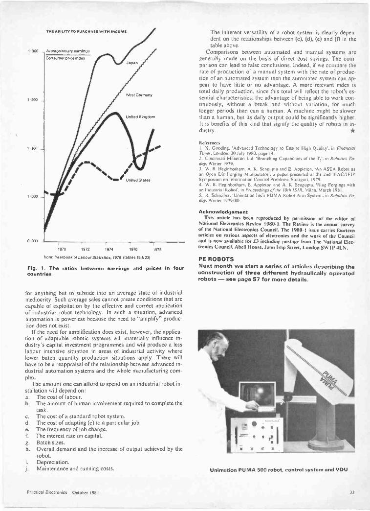
THE ABILITY TO PURCHASE WITH INCOME
1.300 _ Average hourly earnings
Consumer price index
200
1 100
' 000
0-900
Japan
West Germany
United Kingdom
fr,
/I/
"nmr" United Stales
/
1970 1972 1971 1976 1973
from. Yearbook of Labour Statistics, 1979 (tables 18 & 23)
Fig. 1. The ratios between earnings and prices in fourcountries
.or anything but to subside into an average state of industrialmediocrity. Such average sales cannot create conditions that arecapable of exploitation by the effective and correct applicationof industrial robot technology. In such a situation, advancedautomation is powerless because the need to "amplify" produc-tion does not exist.
If the need for amplification does exist, however, the applica-tion of adaptable robotic systems will materially influence in-dustry's capital investment programmes and will produce a lesslabour intensive situation in areas of industrial activity wherelower batch quantity production situations apply. There willhave to be a reappraisal of the relationship between advanced in-dustrial automation systems and the whole manufacturing com-plex.
The amount one can afford to spend on an industrial robot in-stallation will depend on:a. The cost of labour.b. The amount of human involvement required to complete the
task.c. The cost of a standard robot system.d. The cost of adapting (c) to a particular job.e. The frequency of job change.f. The interest rate on capital.g. Batch sizes.h. Overall demand and the increase of output achieved by the
robot.i. Depreciation.j. Maintenance and running costs.
The inherent versatility of a robot system is clearly depen-dent on the relationships between (c). (d). (e) and (f) in thetable above.
Comparisons between automated and manual systems aregenerally made on the basis of direct cost savings. The com-parison can lead to false conclusions. Indeed, if we compare therate of production of a manual system with the rate of produc-tion of an automated system then the automated system can ap-pear to have little or no advantage. A more relevant index istotal daily production, since this total will reflect the robot's es-sential characteristics; the advantage of being able to work con-tinuously, without a break and without variation, for muchlonger periods than can a human. A machine might be slowerthan a human, but its daily output could be significantly higher.It is benefits of this kind that signify the quality of robots in in-dustry.
ReferencesI. K. Gooding. 'Advanced Technology to Ensure High Quality', in FinancialTimes, London. 30 July 1980, page 14.2. Cincinnati Milacron Ltd. 'Branching Capabilities of the T,', in Robotics To-day, Winter 1979.3. W. B. Heginbotham, A. K. Sengupta and E. Appleton. 'An ASEA Robot asan Open Die Forging Manipulator', a paper presented at the 2nd IFAC/IFIPSymposium on Information Control Problems. Stuttgart. 1979.4. W. B. Heginbotham, E. Appleton and A. K. Sengupta, 'Ring Forgings withan Industrial Robot', in Proceedings of the 10th /SIR, Milan. March 1981.5. R. Schreiber. 'Unimation Inc's PUMA Robot Arm System', in Robotics To-day, Winter 1979/80.
AcknowledgementThis article has been reproduced by permission of the editor of
National Electronics Review 1980-1. The Review is the annual surveyof the National Electronics Council. The 1980-I issue carries fourteenarticles on various aspects of electronics and the work of the Counciland is now available for £3 including postage from The National Elec-tronics Council, Abell House, John Islip Street, London SWIP 4LN.
PE ROBOTSNext month we start a series of articles describing theconstruction of three different hydraulically operatedrobots - see page 57 for more details.
Unimation PUMA 500 robot, control system and VDU
Practical Electronics October 1981
UK LISTEX VAT
The first portablescope with acomponent tester.
Capacitor 33 oF Transistor EC Transistor FIE
Oscilloscope Specifications:
Y DeflectionBandwidth: DC - 10 MHz (-3d8)Overshoot: Less than 1%Sensitivity: 5 mV - 20 V/cmInput Imp: 1 M ohm // 25pf
General InformationComponent Tester:Calibrator:Power Supplies:A.C. Input:Weight:Size:
B -E 1 uF r 68ohms
X DeflectionTimebase: 0.2s 0.2.us/cmTriggering: 2 Hz 30 MHz (3mm)
Auto + level controlBandwidth: 2Hz 1 MHz
For single components and In circuit0.2V ± 1% for probe alignmentRegulated including high voltage110, 127. 220, 237, V.A.C., 50- 60 Hz8-V. Lbs.40/2"H x 8-3/81N x 10-7116'D
For further information on HAMEG's full range of topperformance oscilloscopes, contact:
HAMEG LTD.74.78 Collingdon Street, Luton, Beds. LU1 1RXTel: (0582) 413174
NEW! For Atom Owners
VCE C)112tAcorn are right on target with a
whole range of gamesGET THE BEST - FORGET THE RESTAll Acornsoft games are designed and produced by the manufact-urers of the Atom. Trust the manufacturer to get the very best outof his product. Realistic sound effects, great graphics and colour too!
em &&&&&&
0 01 01** *010 0 0 0 0
* * * 0
API AGAMES PACK 1Asteroids Shoot them beforethey crash into you. Lists tenbest scores. Program 4K, graphics6K.Sub Hunt Command a destroyertracking a submarine, find itsposition and destroy it. Program1K, graphics `AK, needs floatingpoint.Breakout Score points knockingbricks from wall. BaIl has twochanges of angle and speedProgram 3K. graphics 1 2K.COLOURGAMES PACK 2Dogfight Two -player gameeach player controls a plane andtries to shoot down his opponentwithout crashing. Program 4K,graphics 6K.Mastermind Guess the cornputer's code before the computergu ours; program 3K,graphics %K.Zombie Land on Zombie island,try to lure all the zombies Intothe swamp. In desperation jumpinto hyperspacel Program 3K.graphics %K. COLOURGAMES PACK 4Star Trek Classic computergame, rid the universe ofKlingons. Short and long-rangescans, galactic map, phasers,photon torpedoes, shields, etc.Program 5K, graphics 2K.Four Row Take turns in placingmarbles on the board, the firstto get a line of four wins.Program 5K, graphics 6K.COLOURSpace Attack Repel theinvasions of earth and avoidbeing hit by the gunner ships.Becomes progressively harderwith each invasion. Program3K, graphics 6K.GAMES PACK 6Dodgems Steer your car andavoid the computer controlledcar programmed to collide.Survive, and the game gets fasterProgram 4K, graphics 6K.Simon Test your ability toremember a progressively longersequence of lights and tones.Adjustable skill level. Program2K, graphics 3K. COLOURAmoeba Try and create theshapes devised by the computer.
SPACE INVADERSThis has proved to be the mostpopular video game ever. Andnow we've brought it right upto date. Different, types ofinvaders, flying saucers, shelters,laser guns and full sound effectsProgram 5K, graphics 6KAlso in Games Pack 5Wumpus r Reversi
GAMES PACK 3Rat Trap Move your rats withoutcolliding with the trails left.Entangle your opponent beforehe entangles youl High speed rataction replay Program 4Kgraphics 6KLunar Lander Land a spacecrafton a lunar crater, altitudevelocity, fuel and drift Program1K, graphics Y.KBlack Box Deduce the positionof four invisible objects in theBlack Box by firing rays at themProgram 4K. graphics ".K
I
GAMES PACK 7Green Things An alien life formhas invaded your spacecraft,discover a way of destroying itwith the weapons available onthe ship. Program 5K, graphics2K. COLOURBallistics Take turns in firingshells at the other player, takinginto account the wind and shapeof the hill, Program 3K. graphics6K, needs floating point.Snake Grow yourself a snake byguiding it towards digits which
Program 3K, graphics 3K. it eats Program 2K, graphics YiKORDER TODAY!
Just send a cheque or money order only E11.50 per packincluding VAT and post and packing. State which packs you want.
Or ring 0223 316039 or 01-930 1614 quoting yourAccess or Barclaycard number. Allow 14 days for delivery.
Or if you think you can wait for more details just write toAcornsoft Limited, 4a Market Hill, Cambridge.
ACORNSeFT TAKE GAMES SERIOUSLY
34 Practical Electronics October 1981
SemiconductorFEATURING OPL100 WD55 LM396
SEE-THROUGH CHIPL.e.d. numeric displays are now available
in a wide range of styles and sizes and canbe used in any application which does notrequire power consumption to be reducedto an absolute minimum. If power is a
problem, then liquid crystal readouts shouldbe considered, but remember that there is abig difference between the light EMITTINGI.e.d. and the purely REFLECTIVE I.c.d.which has a lot in common with the printedpage and its dependency on ambientlighting. The two technologies do competein some areas, but there are also clearlydefined applications where either the I.e.d.or the I.c.d. wins hands down. In digitalwatches, for example, there can be littledoubt that the low consumption of the I.c.d.is the dominant factor despite the con-siderable inconvenience of having toprovide an incandescent backlight for nightviewing. On the other hand, in mainspowered equipment such as digital alarmclocks where ample power is available, thebrightness of the I.e.d. readout and its in-dependence of ambient lighting, make itthe logical choice. The use of I.e.d. readoutsdoes bring some problems, however, andforemost among these is deciding just howbright the display needs to be to competewith any ambient lighting which may bepresent. The range of brightness required tocompete with strong sunshine at one ex-treme and a darkened bedroom at the otheris considerable, and rather than have illeg-ible displays by day and -keep-you-awake"neon signs by night, many clock -radiomanufacturers incorporate a dimmingswitch into their designs to reduce theproblem to manageable proportions.
The provision of just two brightnesslevels is hardly a complete answer to theproblem though, and what is really requiredis a CONTINUOUS adjustment of displaybrightness as the ambient light level altersthroughout the day. You can probably seehow to design one of these. All you need isa photo -detector such as a light dependentresistor or photo -diode, an amplifier, a
voltage controlled pulse width modulator,and a high fanout driver to strobe all thedigits on or off at a fairly high frequencywhich cannot be detected by the humaneye. (You could vary the display voltage,and therefore current, instead of using thestrobe approach but that would meanwasting a lot of power heating up anexpensive power regulator, not to mentionthe problem of a distinctly non-linearvoltage/brightness characteristic.) Although
the concept of an automatic brightnesscontrol is simple enough, the realisation hasusually been too expensive for all but themost up-market equipment, but that situa-tion will soon change thanks to a newdevice from an American firm called TRWOptron.
What TRW Optron have done is to builda complete brightness control integratedcircuit, including an ambient light sensor,into a diminutive eight pin d.i.l. packagemade of see-through plastic The device iscoded OPL100 and it contains a
photodiode, a high gain amplifier, an op -amp and several comparators, a latch,some gating, an output stage and a voltageregulator. A brightness control range ofzero to 100 per cent is possible using thepulse width modulation output to controlthe display duty cycle. The 7447 seven seg-ment decoder which is widely used to driveI.e.d. displays can be directly controlled viaits RBI input; other types of driver may re-quire some gating. Thanks to its internalregulator, the OPL100 can operate fromany available supply from 4.5 to 24 volts,and current drain is constant at around10mA.
The OPL100 could be just the thing forthat digital car instrument panel you havebeen promising yourself'
MICRO TIMERSome time ago I wrote about the CY500
Stepper Motor Controller, which was ac-tually a single chip microprocessor with abuilt-in program designed by a firm otherthan the micro' manufacturer to do aspecial job. Single chip microprocessors arebeing made by the million and they are allbeing manufactured with "built-in"software to do a special job of one kind oranother, although usually they disappearwithout trace into a mass produced productsuch as an automatic washing machine oran electronic game, and are never offeredfor sale to anyone else. Some of thesedevices turn out to be of such general ap-plication however, that their designers DOoffer them for sale to a wider market,recouping their own development costs andmaking a handsome profit into the bargain!
The CY500 was one example of such ageneral purpose development, and thismonth I would like to :ell you aboutanother, the WD 55 from Western Digital,distributed in the UK by Jee Distribution ofHayes, Middlesex. This interesting deviceis a mask programmed member of theWD 50 family of four bit single chip
ElmR.W. Coles
microprocessors, dedicated by the internalprogram ROM to perform the function of acapable timer system able to replace andout -perform timers currently using motors,gears, cams, and micro -switches. The WD55 has two basic operating modes; thesimplest of these requires very few externalcomponents and relies on an array ofthumbwheel switches or even diodes to getthe desired ON/OFF timing intervals with arange of up to 999 hours and a resolutionof 0.1 second. The second mode is selectedby a strapping option, and interfaces theWD 55 to a numeric keyboard matrix and aseven segment I.e.d. display to perform thefunction of a fully programmable timer/se-quencer with up to seven sequentialON/OFF timing periods. In either mode thetiming reference can be 50/60Hz mains fre-quency or an external crystal oscillator, andtiming operations can be continuous orsingle shot. The timer outputs are capableof driving relays or triacs, and an alarm out-put is available to sound a buzzer at counttermination if required. The use of simplemembrane switch keypads is made easierby the provision of audible feedback via thealarm output to signify the proper actuationof keys which give little or no tactileresponse.
The WD 55 is made with PMOStechnology, lives in a 40 -pin plastic orceramic DIP, and runs from nominally 13.2volt supplies. I can think of all kinds of usesfor it, how about you?
MOOSEIt seemed quite wonderful to me when
someone first squashed a 1 amp 5 voltregulator circuit into a TO3 can. A wholeamp I thought, that will keep my TTLhappy! Since then we have seen 1.5 amp 2amp and even 5 amp regulators in the samecan and I for one thought that NOBODYwould ever be able to do any better thanthat, until I saw the National LM 396. Thisdevice, known to its friends as MOOSE, canprovide an astonishing TEN amps at powerlevels of up to 70 watts without evenstarting to melt its little T03 package(provided it's on a heat sink of course!).
National have performed the trick bybringing together on one chip the best dis-crete power transistor and linear amplifierdesign principles. The MOOSE is voltageadjustable over a 1.25 to 15 volt range,and has excellent line and load regulation. Ifyou are planning any arc welding, theLM 396 could be for you
Practical Electronics October 1981 35
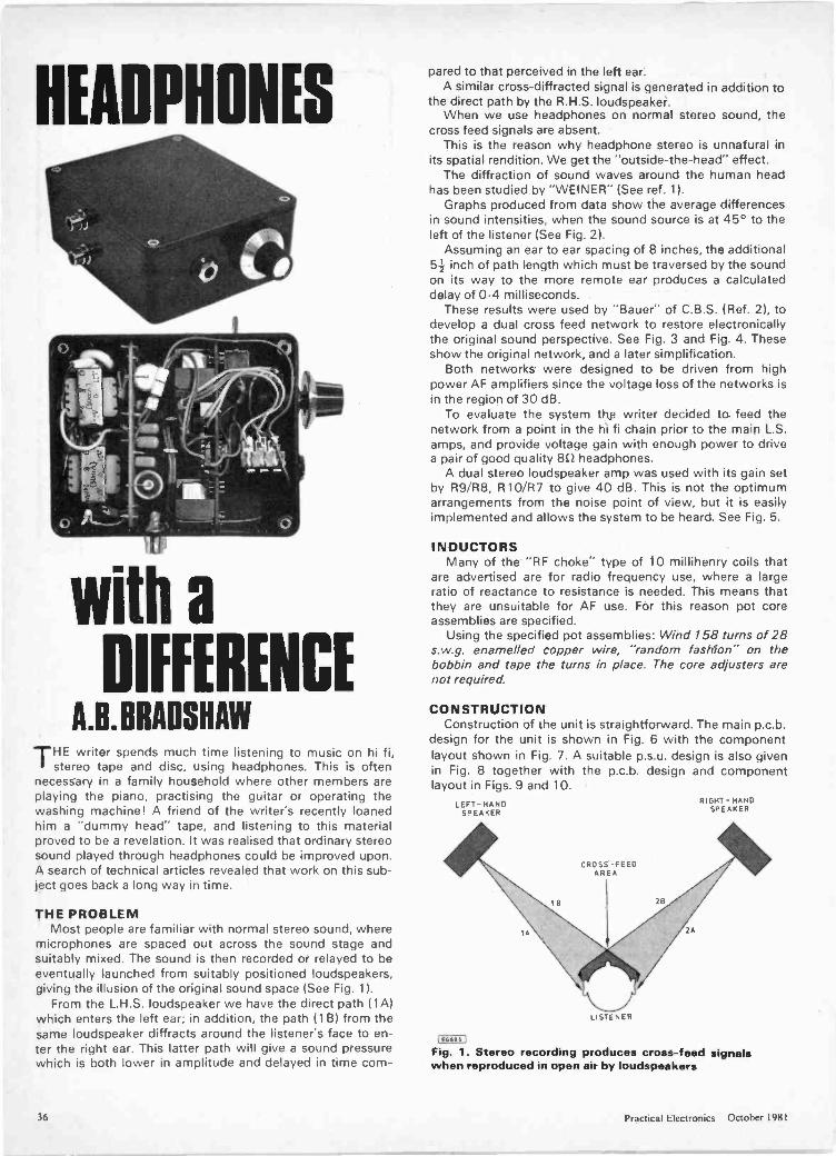
HEADPHONES
with a
DIFFERENCEA.B.BRADSNAW
THE writer spends much time listening to music on hi fi,stereo tape and disc, using headphones. This is often
necessary in a family household where other members areplaying the piano, practising the guitar or operating thewashing machine! A friend of the writer's recently loanedhim a "dummy head" tape, and listening to this materialproved to be a revelation. It was realised that ordinary stereosound played through headphones could be improved upon.A search of technical articles revealed that work on this sub-ject goes back a long way in time.
THE PROBLEMMost people are familiar with normal stereo sound, where
microphones are spaced out across the sound stage andsuitably mixed. The sound is then recorded or relayed to beeventually launched from suitably positioned loudspeakers,giving the illusion of the original sound space (See Fig. 1).
From the L.H.S. loudspeaker we have the direct path (1A)which enters the left ear; in addition, the path ( 1 B) from thesame loudspeaker diffracts around the listener's face to en-ter the right ear. This latter path will give a sound pressurewhich is both lower in amplitude and delayed in time corn -
pared to that perceived in the left ear.A similar cross -diffracted signal is generated in addition to
the direct path by the R.H.S. loudspeaker.When we use headphones on normal stereo sound, the
cross feed signals are absent.This is the reason why headphone stereo is unnatural in
its spatial rendition. We get the "outside -the -head" effect.The diffraction of sound waves around the human head
has been studied by "WEINER" (See ref. 1).Graphs produced from data show the average differences
in sound intensities, when the sound source is at 45° to theleft of the listener (See Fig. 2).
Assuming an ear to ear spacing of 8 inches, the additional54- inch of path length which must be traversed by the soundon its way to the more remote ear produces a calculateddelay of 0.4 milliseconds.
These results were used by "Bauer" of C.B.S. (Ref. 2), todevelop a dual cross feed network to restore electronicallythe original sound perspective. See Fig. 3 and Fig. 4. Theseshow the original network, and a later simplification.
Both networks were designed to be driven from highpower AF amplifiers since the voltage loss of the networks isin the region of 30 dB.
To evaluate the system the writer decided to feed thenetwork from a point in the hi fi chain prior to the main L.S.amps, and provide voltage gain with enough power to drivea pair of good quality 8C headphones.
A dual stereo loudspeaker amp was used with its gain setby R9/R8, R10/137 to give 40 dB. This is not the optimumarrangements from the noise point of view, but it is easilyimplemented and allows the system to be heard. See Fig. 5.
INDUCTORSMany of the "RF choke" type of 10 millihenry coils that
are advertised are for radio frequency use, where a largeratio of reactance to resistance is needed. This means thatthey are unsuitable for AF use. For this reason pot coreassemblies are specified.
Using the specified pot assemblies: Wind 158 turns of 28s.w.g. enamelled copper wire, "random fashion" on thebobbin and tape the turns in place. The core adjusters arenot required.
CONSTRUCTIONConstruction of the unit is straightforward. The main p.c.b.
design for the unit is shown in Fig. 6 with the componentlayout shown in Fig. 7. A suitable p.s.u. design is also givenin Fig. 8 together with the p.c.b. design and componentlayout in Figs. 9 and 10.
LEFT-HANDSPEAKER
CROSS -FEEDAREA
LISTENER
2A
RIGHT-HANDSPEAKER
(E0Gg61
Fig. 1. Stereo recording produces cross -feed signalswhen reproduced in open air by loudspeakers
36 Practical Electronics October 1981
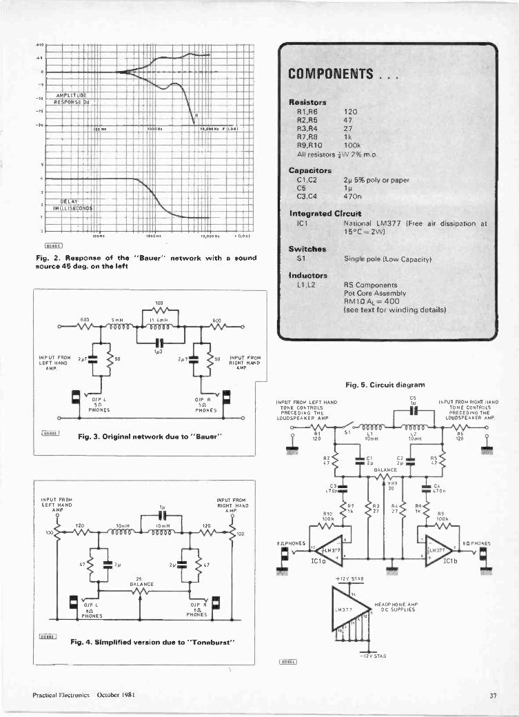
+10
+5
a
10
-IS
-00
2
0
AMPLREPO 4Sr
R
Ma SO Na 10 000Na Loal
IN1
L
LLI iE ilb
160 69 S I
100az 1000111 0,000 Mr 1L001
Fig. 2. Response of the "Bauer" network with a soundsource 45 deg. on the left
INPUT FROM 2p7LEFT HAND
AMP
100
9rn H 600
50 INPUT FROMRIGHT HAND
AMP
0/P L 0/P R
0PHONES
511PHONES5 II
0
1 E011113 1 Fig. 3. Original network due to "Bauer"
INPUT FROMLEFT HAND
AMP
_692
INPUT FROMRIGHT HAND
A MP
J/P L611
PHONES
Fig. 4. Simplified version due to "Toneburst"
COMPONENTS . . .
ResistorsR1,R6 120R2,R5 47R3,R4 27R7,R8 1kR9,R10 100kAll resistors ,.\N 2% m.o.
CapacitorsCl,C2 2115% poly or paperC5C3,C4 470n
Integrated CircuitIC1 National LM377 (Free air dissipation at
15°C = 2W)
SwitchesS 1
InductorsL1,L2
Single pole (Low Capacity)
RS ComponentsPot Core AssemblyRM1D AL= 400(see text for winding details)
INPUT FROM LEFT HANDTONE CONTROLSPRECEDING THE
LOUDSPEAKER AMP
0.11PHONES
R1120
R267
C3470r
R10100k
ICla
Fig. 5. Circuit diagram
+12v
7 R327
ST aB
Rb16
HEADPHONE AMPDC SUPPLIES
TAB
INPUT FROM RIGHT HANDTO NE CONTROLSPRECEDING THE
LOUDSPEAKER AMP.
R6120
44470n
IC1b
BrI PHONES
Practical Electronics October 1981 37
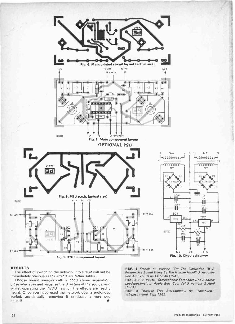
E 19.:
teN3d
6 Fig. 6. 6. Main printed circuit layout (actual size)1/R1 TO VR1TO VR1
EARTH
S1 -vE +VE 0/P2 0/P1
Fig. 7. Main component layout
OPTIONAL PSU
3d
Fig. 8. PSU p.c.b. (actual size)
C1
Fig. 9. PSU component layout
RESULTSThe effect of switching the network into circuit will not be
immediately obvious as the effects are rather subtle.Choose sound sources with a good stereo separation,
close your eyes and visualise the direction of the source, andwhilst operating the IN/OUT switch the effects are readilyheard. Once you have used the network over a prolongedperiod, accidentally removing it produces a very oddsound!
T1 SEC
T1 SEC
L 240V
Lk 0 0 0 WST1
E L 240V
1-NSLOOQS000r-i
- 2V OV +12V
Fig. 10. Circuit diagram
REF. 1 Francis M. Weiner, "On The Diffraction Of AProgressive Sound Wave By The Human Head". J. AcousticSoc. Am: Vol 19 pc 143-14611947).REF. 2 B. B. Bauer, "Stereophonic Earphones And BinauralLoudspeakers". J. Audio Eng. Soc. Vol 9 number 2 April(1961)REF. 3 Towaras True Stereophony. By ''Toneburst".Wireless World, Sept 1969.
T2
38 Practical Electronics October 1981

CHOOSE ATOM POWERAt work or play- everything you need in a personal computer
The Atom is a machine to be usedEvery day, day after day. It's a fullfunction machine- check thespecification against others. It'srugged, easy to operate built to la itand features a full-size typewriterkeyboard.Just look at some of the features! More hardware support than any othe -microcomputer Superfast BASIC - cm beupdated to BBC BASIC if required High resolution and comprehensivegraphics ideal for games programmers cndplayers* Integral printer connection* Software available for games, educat:on,maths, graphs, business, word processing, etc. Other languages: Pascal, FORTH, LISP I/O port for control of external devices Built-in loudspeaker Cassette interlace Full service/repair facility Users clt_b
' Espanded verslan ar.1y
Optional Extras Netwcrk facility with Econet Disk PAL UHF colour encoder Add-cn cards include 32K memory,analogue to digital, viewdata VDU, diskcontroller, daisywheel printer, plus many,many more! Power supplyFREE MANUALThe Atom's highly acclaimed manual comesfree with every Atom and leaves nothing out :njust a whie you'll be completely at ease withyour nev machine! Within hatizs you'll bewriting y DUI own prograrr s.
Dealers or Mail OrderComputer stores are stocking Atoms - there's a list below but if you have any pr nblems gettinghold of one just fill in the coupon and well rush one to ycu within 28 days. If the machine isn'tall you expected, or all we've told you, just return it within 14 days for a full refund.MOM, Aberdeen 22863. Broadway Electronics, Bedford. Owl Computers, Bishops Stortford,52682. Eltec Services, Bradford 491371. Gamer, Brighton 698424. Electronic InformationSystems, Bristol 774564. Cambridge Comp Store, Cambridge 65334. Cardiff Micros, Cardiff373072. Emprise, Colchester 865926. Silicon Centre, Edinburgh 332 527". Esco Computing,Glasgow 204 1811. Control Universal Harlow 31604. Unitron Electronics. Haslington. CastleElectronics, Hastings 437875. Currys Micro Systems, High Wycombe. Microd:gital, Liverpool 2360707. Barrie Electronics. London 488 3316. Off Records, SW12. Technomatic, NWIO 452 1500.H.C.C.S., Low Fell 821924. NSC Conip Shops, Manchester 832 2269. Compshop, New Barnet441 2922. Newbear Comp Store, Newbury 30505. Newcastle Comp Services. Newcastle 615325.Anglia Comp Store, Norwich 29652. Leasalink Viewdata, Nottingham 396976. CustomizedElect, Redcar 481460. Computers fo- All, Romford 751906. Intelligent Artefacts, Royston,Arrington 689. Quadraphenia, Sheffielc 77824. Q-TEK Systems, Stevenage 65385. 3D Computers,Surbiton (01) 337 4317. Computer Supplies, Swansea 290047. Abacus Micro Comp, Tonbridge,Paddock Wood 3861.Northern Comp, Warrington 601683.
YOU AND YOUR CHILDREN
More and more schools are buying Atoms.More and more children will learn on an Atom.You can give them that extra familiarity with anAtom in the home.
ACORNO R
4a Market Hill,C CAMBRIDGE CB2 3NJr -
When you order your Atom we will includefull details of all software packs and theoptional hardwareTo: Acorn Computer Limited, 4A Market Hill,Cambridge CB2 3NJ.
[ enclose a cheque/postal order for £Please debit my Access/Barclaycard NoSignatureName (please print)Address
Telephone NumberRegistered No 1403810 VAT No 215 400 220
Item price inc.Quantity Item VAT + P&P Totals
Atom Krt BK ROM+ Ca E140032K RAMAtom Assembled 8K @ 074 50ROM+ 2K RAMAtom Assembled 12K P E289 SOROM+ I2K RAMPower Supply @E 10 20
TOTAL
Practical Electronics October 1981 39
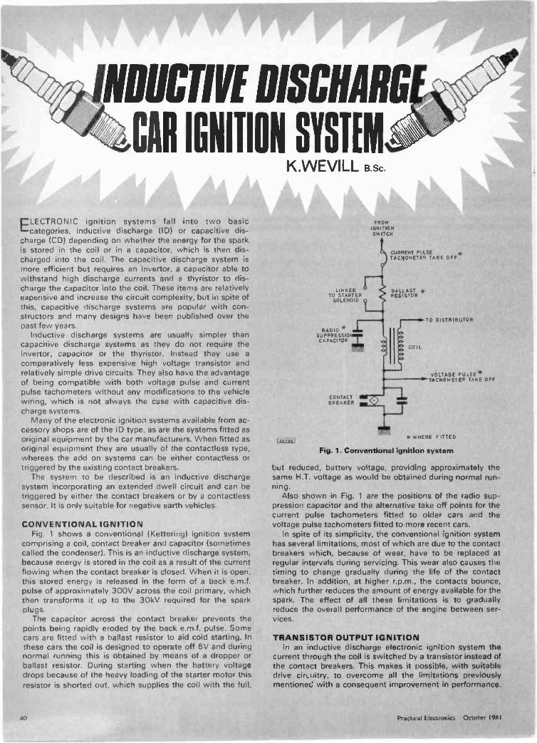
NDUCTIVE DISCHARG
CAR IGNITION SYSTEMK.WEVILL B.Sc.
ELECTRONIC ignition systems fall into two basiccategories, inductive discharge (ID) or capacitive dis-
charge (CD) depending on whether the energy for the sparkis stored in the coil or in a capacitor, which is then dis-charged into the coil. The capacitive discharge system ismore efficient but requires an invertor, a capacitor able towithstand high discharge currents and a thyristor to dis-charge the capacitor into the coil. These items are relativelyexpensive and increase the circuit complexity, but in spite ofthis, capacitive discharge systems are popular with con-structors and many designs have been published over thepast few years.
Inductive discharge systems are usually simpler thancapacitive discharge systems as they do not require theinvertor, capacitor or the thyristor. Instead they use acomparatively less expensive high voltage transistor andrelatively simple drive circuits. They also have the advantageof being compatible with both voltage pulse and currentpulse tachometers without any modifications to the vehiclewiring, which is not always the case with capacitive dis-charge systems.
Many of the electronic ignition systems available from ac-cessory shops are of the ID type, as are the systems fitted asoriginal equipment by the car manufacturers. When fitted asoriginal equipment they are usually of the contactless type,whereas the add on systems can be either contactless ortriggered by the existing contact breakers.
The system to be described is an inductive dischargesystem incorporating an extended dwell circuit and can betriggered by either the contact breakers or by a contactlesssensor. It is only suitable for negative earth vehicles.
CONVENTIONAL IGNITIONFig. 1 shows a conventional (Kettering) ignition system
comprising a coil, contact breaker and capacitor (sometimescalled the condenser). This is an inductive discharge system,because energy is stored in the coil as a result of the currentflowing when the contact breaker is closed. When it is open,this stored energy is released in the form of a back e.m.f.pulse of approximately 300V across the coil primary, whichthen transforms it up to the 30kV required for the sparkplugs.
The capacitor across the contact breaker prevents thepoints being rapidly eroded by the back e.m.f. pulse. Somecars are fitted with a ballast resistor to aid cold starting. Inthese cars the coil is designed to operate off 6V and duringnormal running this is obtained by means of a dropper orballast resistor. During starting when the battery voltagedrops because of the heavy loading of the starter motor thisresistor is shorted out, which supplies the coil with the full,
1E6,00'
LINKEDTO STARTER
SOLENOID
RADIO *
CAPACITOR
CONTACBREAKER
FROMIGNITIONSW ITCH
CURRENT PULSETACHOMETER TAKE OFF
BALLAST *-RESISTOR
COIL
TO DISTRIBUTOR
VOLTAGE PULSE*TACHOMETER TAKE OFF
if WHERE FITTED
Fig. 1. Conventional ignition system
but reduced, battery voltage, providing approximately thesame H.T. voltage as would be obtained during normal run-ning.
Also shown in Fig. 1 are the positions of the radio sup-pression capacitor and the alternative take off points for thecurrent pulse tachometers fitted to older cars and thevoltage pulse tachometers fitted to more recent cars.
In spite of its simplicity, the conventional ignition systemhas several limitations, most of which are due to the contactbreakers which, because of wear, have to be replaced atregular intervals during servicing. This wear also causes thetiming to change gradually during the life of the contactbreaker. In addition, at higher r.p.m., the contacts bounce,which further reduces the amount of energy available for thespark. The effect of all these limitations is to graduallyreduce the overall performance of the engine between ser-vices.
TRANSISTOR OUTPUT IGNITIONIn an inductive discharge electronic ignition system the
current through the coil is switched by a transistor instead ofthe contact breakers. This makes it possible, with suitabledrive circuitry, to overcome all the limitations previouslymentioned with a consequent improvement in performance.
40 Practical Electronics October 1981
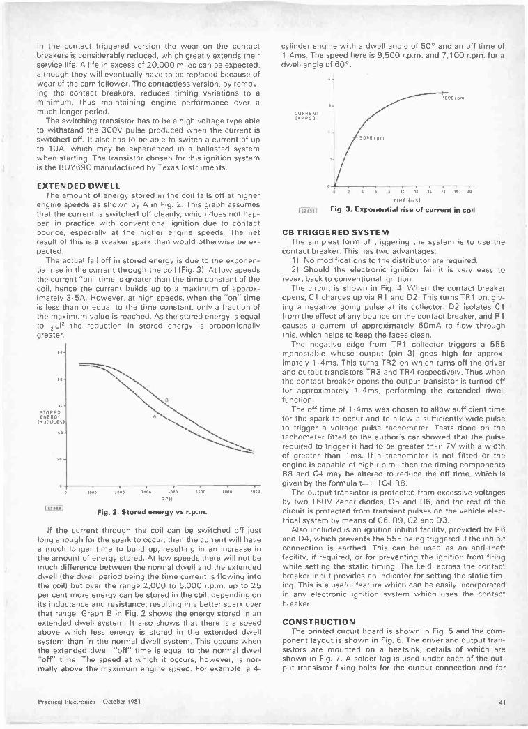
In the contact triggered version the wear on the contactbreakers is considerably reduced, which greatly extends theirservice life. A life in excess of 20,000 miles can be expected,although they will eventually have to be replaced because ofwear of the cam follower. The contactless version, by remov-ing the contact breakers, reduces timing variations to aminimum, thus maintaining engine performance over amuch longer period.
The switching transistor has to be a high voltage type ableto withstand the 300V pulse produced when the current isswitched off. It also has to be able to switch a current of upto 10A, which may be experienced in a ballasted systemwhen starting. The transistor chosen for this ignition systemis the BUY69C manufactured by Texas Instruments.
EXTENDED DWELLThe amount of energy stored in the coil falls off at higher
engine speeds as shown by A in Fig. 2. This graph assumesthat the current is switched off cleanly, which does not hap-pen in practice with conventional ignition due to contactbounce, especially at the higher engine speeds. The netresult of this is a weaker spark than would otherwise be ex-pected.
The actual fall off in stored energy is due to the exponen-tial rise in the current through the coil (Fig. 3). At low speedsthe current "on" time is greater than the time constant of thecoil, hence the current builds up to a maximum of approx-imately 3.5A. However, at high speeds, when the "on" timeis less than or equal to the time constant, only a fraction ofthe maximum value is reached. As the stored energy is equalto ILI' the reduction in stored energy is proportionallygreater.
100
SO
00'STOREDENERGY
1rnIOULES)
40
SO
0
00500]
1000 2000 3000 4000
RPM
5000 40110 7000
Fig. 2. Stored energy vs r.p.m.
If the current through the coil can be switched off justlong enough for the spark to occur, then the current will havea much longer time to build up, resulting in an increase inthe amount of energy stored. At low speeds there will not bemuch difference between the normal dwell and the extendeddwell (the dwell period being the time current is flowing intothe coil) but over the range 2,000 to 5,000 r.p.m. up to 25per cent more energy can be stored in the coil, depending onits inductance and resistance, resulting in a better spark overthat range. Graph B in Fig. 2 shows the energy stored in anextended dwell system. It also shows that there is a speedabove which less energy is stored in the extended dwellsystem than in the normal dwell system. This occurs whenthe extended dwell "off" time is equal to the normal dwell"off" time. The speed at which it occurs, however, is nor-mally above the maximum engine speed. For example, a 4 -
cylinder engine with a dwell angle of 50° and an off time of1.4ms. The speed here is 9,500 r.p.m. and 7,100 r.pm. for adwell angle of 60°.
CURRENT(AMPS I
I-COT-991
4.
5000 rpm
WOO rpm
0 2 4 6 11 10 12 it 70 II 20
TIME (mS)
Fig. 3. Exponential rise of current in coil
CB TRIGGERED SYSTEMThe simplest form of triggering the system is to use the
contact breaker. This has two advantages:1) No modifications to the distributor are required.2) Should the electronic ignition fail it is very easy to
revert back to conventional ignition.The circuit is shown in Fig. 4. When the contact breaker
opens, C1 charges up via R1 and D2. This turns TR 1 on, giv-ing a negative going pulse at its collector. D2 isolates C1from the effect of any bounce on the contact breaker, and R1causes a current of approximately 60mA to flow throughthis, which helps to keep the faces clean.
The negative edge from TR1 collector triggers a 555monostable whose output (pin 3) goes high for approx-imately 1.4ms. This turns TR2 on which turns off the driverand output transistors TR3 and TR4 respectively. Thus whenthe contact breaker opens the output transistor is turned offfor approximate y 1.4ms, performing the extended dwellfunction.
The off time of 1.4ms was chosen to allow sufficient timefor the spark to occur and to allow a sufficiently wide pulseto trigger a voltage pulse tachometer. Tests done on thetachometer fitted to the author's car showed that the pulserequired to trigger it had to be greater than 7V with a widthof greater than 1 ms. If a tachometer is not fitted or theengine is capable of high r.p.m., then the timing componentsR8 and C4 may be altered to reduce the off time, which isgiven by the formula t=1.1C4 R8.
The output transistor is protected from excessive voltagesby two 160V Zener diodes, D5 and D6, and the rest of thecircuit is protected from transient pulses on the vehicle elec-trical system by means of C6, R9, C2 and D3.
Also included is an ignition inhibit facility, provided by R6and D4, which prevents the 555 being triggered if the inhibitconnection is earthed. This can be used as an anti -theftfacility, if required, or for preventing the ignition from firingwhile setting the static timing. The I.e.d. across the contactbreaker input provides an indicator for setting the static tim-ing. This is a useful feature which can be easily incorporatedin any electronic ignition system which uses the contactbreaker.
CONSTRUCTIONThe printed circuit board is shown in Fig. 5 and the com-
ponent layout is shown in Fig. 6. The driver and output tran-sistors are mounted on a heatsink, details of which areshown in Fig. 7. A solder tag is used under each of the out-put transistor fixing bolts for the output connection and for
Practical Electronics October 1981 4I
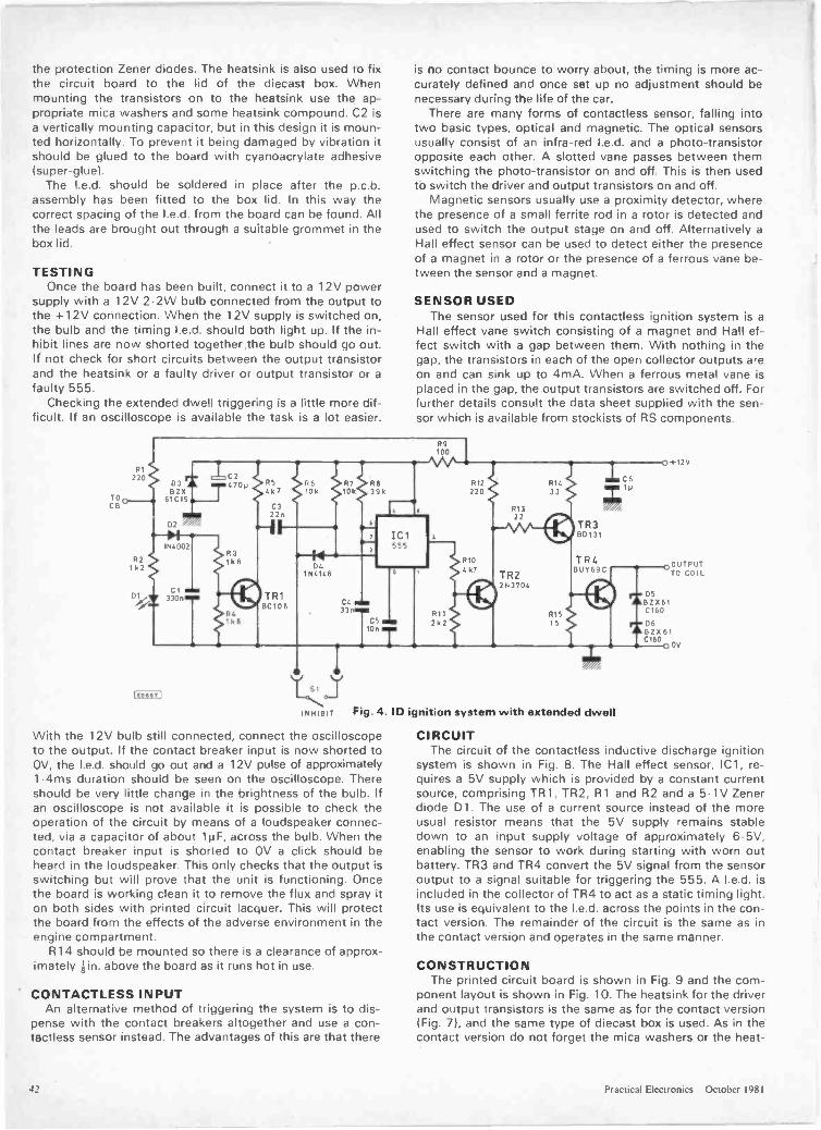
the protection Zener diodes. The heatsink is also used to fixthe circuit board to the lid of the diecast box. Whenmounting the transistors on to the heatsink use the ap-propriate mica washers and some heatsink compound. C2 isa vertically mounting capacitor, but in this design it is moun-ted horizontally. To prevent it being damaged by vibration itshould be glued to the board with cyanoacrylate adhesive(super -glue).
The I.e.d. should be soldered in place after the p.c.b.assembly has been fitted to the box lid. In this way thecorrect spacing of the I.e.d. from the board can be found. Allthe leads are brought out through a suitable grommet in thebox lid.
TESTINGOnce the board has been built, connect it to a 12V power
supply with a 12V 2.2W bulb connected from the output tothe +12V connection. When the 12V supply is switched on,the bulb and the timing I.e.d. should both light up. If the in-hibit lines are now shorted together.the bulb should go out.If not check for short circuits between the output transistorand the heatsink or a faulty driver or output transistor or afaulty 555.
Checking the extended dwell triggering is a little more dif-ficult. If an oscilloscope is available the task is a lot easier.
TOCB
RI220
R21 k 2
DI
D3BZX
61 C15
D2
Pi154002
CI330n
5
457
C322n
TR1BCIOB
C510n
is no contact bounce to worry about, the timing is more ac-curately defined and once set up no adjustment should benecessary during the life of the car.
There are many forms of contactless sensor, falling intotwo basic types, optical and magnetic. The optical sensorsusually consist of an infra -red I.e.d. and a photo -transistoropposite each other. A slotted vane passes between themswitching the photo -transistor on and off. This is then usedto switch the driver and output transistors on and off.
Magnetic sensors usually use a proximity detector, wherethe presence of a small ferrite rod in a rotor is detected andused to switch the output stage on and off. Alternatively aHall effect sensor can be used to detect either the presenceof a magnet in a rotor or the presence of a ferrous vane be-tween the sensor and a magnet.
SENSOR USEDThe sensor used for this contactless ignition system is a
Hall effect vane switch consisting of a magnet and Hall ef-fect switch with a gap between them. With nothing in thegap, the transistors in each of the open collector outputs areon and can sink up to 4mA. When a ferrous metal vane isplaced in the gap, the output transistors are switched off. Forfurther details consult the data sheet supplied with the sen-sor which is available from stockists of RS components.
R9100
TR22N3704
C61ti
TR3130131
0+12V
TR4BUY69C
0 TOOU TcPoUT
R1515
Fig. 4. ID ignition system with extended dwell
With the 12V bulb still connected, connect the oscilloscopeto the output. If the contact breaker input is now shorted toOV, the I.e.d. should go out and a 12V pulse of approximately1.4ms duration should be seen on the oscilloscope. Thereshould be very little change in the brightness of the bulb. Ifan oscilloscope is not available it is possible to check theoperation of the circuit by means of a loudspeaker connec-ted, via a capacitor of about 1µF, across the bulb. When thecontact breaker input is shorted to OV a click should beheard in the loudspeaker. This only checks that the output isswitching but will prove that the unit is functioning. Oncethe board is working clean it to remove the flux and spray iton both sides with printed circuit lacquer. This will protectthe board from the effects of the adverse environment in theengine compartment.
R14 should be mounted so there is a clearance of approx-imately gin. above the board as it runs hot in use.
CONTACTLESS INPUTAn alternative method of triggering the system is to dis-
pense with the contact breakers altogether and use a con -tactless sensor instead. The advantages of this are that there
05BZX 610160
D6BZX 61C160
00V
CIRCUITThe circuit of the contactless inductive discharge ignition
system is shown in Fig. 8. The Hall effect sensor, IC1, re-quires a 5V supply which is provided by a constant currentsource, comprising TR1, TR2, R1 and R2 and a 5.1V Zenerdiode D 1 . The use of a current source instead of the moreusual resistor means that the 5V supply remains stabledown to an input supply voltage of approximately 6.5V,enabling the sensor to work during starting with worn outbattery. TR3 and TR4 convert the 5V signal from the sensoroutput to a signal suitable for triggering the 555. A I.e.d. isincluded in the collector of TR4 to act as a static timing light.Its use is equivalent to the I.e.d. across the points in the con-tact version. The remainder of the circuit is the same as inthe contact version and operates in the same manner.
CONSTRUCTIONThe printed circuit board is shown in Fig. 9 and the com-
ponent layout is shown in Fig. 10. The heatsink for the driverand output transistors is the same as for the contact version(Fig. 7), and the same type of diecast box is used. As in thecontact version do not forget the mica washers or the heat -
42 Practical Electronics October 1981
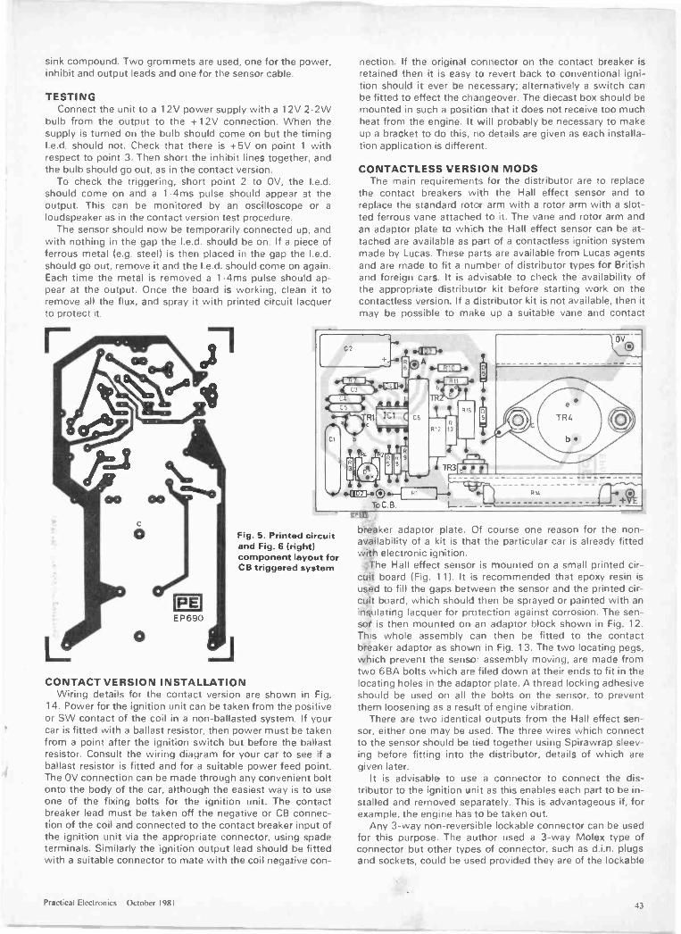
sink compound. Two grommets are used, one for the power,inhibit and output leads and one for the sensor cable.
TESTINGConnect the unit to a 12V power supply with a 12V 2.2W
bulb from the output to the +12V connection. When thesupply is turned on the bulb should come on but the timingI.e.d. should not. Check that there is +5V on point 1 withrespect to point 3. Then short the inhibit lines together, andthe bulb should go out, as in the contact version.
To check the triggering, short point 2 to OV, the I.e.d.should come on and a 1 .4ms pulse should appear at theoutput. This can be monitored by an oscilloscope or aloudspeaker as in the contact version test procedure.
The sensor should now be temporarily connected up, andwith nothing in the gap the I.e.d. should be on. If a piece offerrous metal (e.g. steel) is then placed in the gap the I.e.d.should go out, remove it and the I.e.d. should come on again.Each time the metal is removed a 1.4ms pulse should ap-pear at the output. Once the board is working, clean it toremove all the flux, and spray it with printed circuit lacquerto protect it.
nection. If the original connector on the contact breaker isretained then it is easy to revert back to conventional igni-tion should it ever be necessary; alternatively a switch canbe fitted to effect the changeover. The diecast box should bemounted in such a position that it does not receive too muchheat from the engine. It will probably be necessary to makeup a bracket to do this, no details are given as each installa-tion application is different.
CONTACTLESS VERSION MODSThe main requirements for the distributor are to replace
the contact breakers with the Hall effect sensor and toreplace the standard rotor arm with a rotor arm with a slot-ted ferrous vane attached to it. The vane and rotor arm andan adaptor plate tc whicn the Hall effect sensor can be at-tached are available as part of a contactless ignition systemmade by Lucas. These parts are available from Lucas agentsand are made to fit a number of distributor types for Britishand foreign cars. It is advisable to check the availability ofthe appropriate distributor kit before starting work on thecontactless version. If a cistributor kit is not available, then itmay be possible to make up a suitable vane and contact
Fig. 5. Printed circuitand Fig. 6 (right)component layout forCB triggered system
CONTACT VERSION INSTALLATIONWiring details for the contact version are shown in Fig.
14. Power for the ignition unit can be taken from the positiveor SW contact of the coil in a non -ballasted system. If yourcar is fitted with a ballast resistor, then power must be takenfrom a point after the ignition switch but before the ballastresistor. Consult the wiring diagram for your car to see if aballast resistor is fitted and for a suitable power feed point.The OV connection can be made through any convenient boltonto the body of the car, although the easiest way is to useone of the fixing bolts for the ignition unit. The contactbreaker lead must be taken off the negative or CB connec-tion of the coil and connected to the contact breaker input ofthe ignition unit via the appropriate connector, using spadeterminals. Similarly the ignition output lead should be fittedwith a suitable connector to mate with the coil negative con -
breaker adaptor plate. Of course one reason for the non -availability of a kit is that the particular car is already fittedwith electronic ignition.
*the Hall effect sensor is mounted on a small printed cir-cuit board (Fig. 11). It is recommended that epoxy resin isused to fill the gaps between the sensor and the printed cir-cuit board, which should then be sprayed or painted with aninsulating lacquer for protection against corrosion. The sen-sot is then mounted on an adaptor block shown in Fig. 12.This whole assembly can then be fitted to the contactbteaker adaptor as shown in Fig. 13. The two locating pegs,which prevent the sensor assembly moving, are made fromtwo 6BA bolts which are filed down at their ends to fit in thelocating holes in the adaptor plate. A thread locking adhesiveshould be used on all the bolts on the sensor, to preventthem loosening as a result of engine vibration.
There are two identical outputs from the Hall effect sen-sor, either one may be used. The three wires which connectto the sensor should be tied together using Spirawrap sleev-ing before fitting into the distributor, details of which aregiven later.
It is advisable to use a connector to connect the dis-tributor to the igrition unit as this enables each part to be in-stalled and removed separately. This is advantageous if, forexample, the engine has to be taken out.
Any 3 -way non-reve-sible lockable connector can be usedfor this purpose. The author used a 3 -way Molex type ofconnector but otner types of connector, such as d.i.n. plugsand sockets, could be used provided they are of the lockable
Practical Electronics October 1981 43
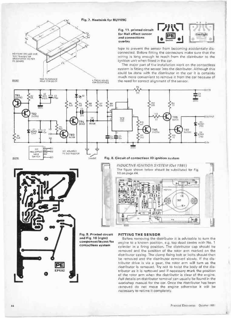
Fig. 7. Heatsink for BUY69C
4.*131115/,
HEATSINK DRILLED FORTO3 TRANSISTORORIENTATION AS PERPC BOARD
lEA212jABA CLEARANCEHOLE FOR BD131
TR1 R2210702 68
',k8
IF82811
2N3702
ICIHALL EFFECT
VANESWITCH
2h1<
13C108
ICI MOUNTEDON DISTRIBUTOR
4 FAXING HOLES4BA CLEARANCE
DC
141N4148
O
6-0
INHIBIT
R710k
R12 1914
220 33
R13
22
TR52N3704
Fig. 11. printed circuitfor Hall effect sensorand connectionsoverlay
[jjEA285
type to prevent the sensor from becoming accidentally dis-connected. Before fitting the connectors make sure that thewiring is long enough to reach from the distributor to theignition unit when fitted in the car.
The major part of the installation work on the contactlesssystem is fitting the sensor into the distributor. Although thiscould be done with the distributor in the car it is certainlymuch more convenient to remove it from the car because ofthe need for correct alignment of the sensor.
R9
ttttC4 C5T33n 10n
TR680131
R15
Fig. 8. Circuit of contactless ID ignition system
Fig. 9. Printed circuitand Fig. 10 (right)component layout forcontactless system
CS +126
-8-0OUTPUT
TR7BUY69C
OSBZX6I
C160
061
INDUCTIVE IGNITION SYSTEM (Oct 1981)The figure shown below should be substituted for Fig.10 on page 44.
C160
00V
FITTING THE SENSORBefore removing the distributor it is advisable to turn the
engine to a known position, e.g. top dead centre with No. 1cylinder in a firing position. The distributor cap should beremoved and the position of the rotor arm marked on thedistributor casing. The clamp fixing bolt or bolts should thenbe removed and the distributor removed slowly. If the dis-tributor drive is via a gear, the rotor arm will turn as thedistributor is removed. Try not to twist the body of the dis-tributor as it is removed and if necessary mark the positionof the rotor arm when the distributor is clear of the engine.Full details on distributor removal can usually be found in theworkshop manual for the car. Once the distributor has beenremoved do not move the engine otherwise it will benecessary to retime it completely.
1.1 Practical Electronics October 1981
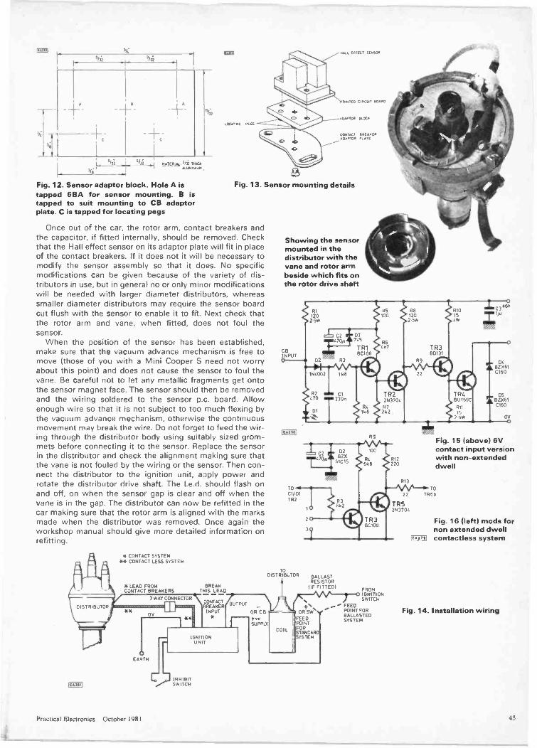
2/3.2 9/3i
5/3i-
'6i .1 tAILEIti. 362 T ICK4.1.101INIUN
Fig. 12. Sensor adaptor block. Hole A istapped 6BA for sensor mounting. B istapped to suit mounting to CB adaptorplate. C is tapped for locating pegs
IOU
LOCATING KOS
NAAL EFFECT SENSOR
PRINTED CIRCUT BOARD
ADAPTOR BLOCP
CONTACT BRENERa01100 PLAT
Fig. 13. Sensor mounting deta:Is
Once out of the car, the rotor arm, contact breakers andthe capacitor, if fitted internally, should be removed. Checkthat the Hall effect sensor on its adaptor plate will fit in placeof the contact breakers. If it does not it will be necessary tomodify the sensor assembly so that it does. No specificmodifications can be given because of the variety of dis-tributors in use, but in general no or only minor modificationswill be needed with larger diameter distributors, whereassmaller diameter distributors may require the sensor boardcut flush with the sensor to enable it to fit. Next check thatthe rotor arm and vane, when fitted, does not foul thesensor.
When the position of the sensor has been established,make sure that the vacuum advance mechanism is free tomove (those of you with a Mini Cooper S need not worryabout this point) and does not cause the sensor to foul thevane. Be careful not to let any metallic fragments get ontothe sensor magnet face. The sensor should then be removedand the wiring soldered to the sensor p.c. board. Allowenough wire so that it is not subject to too much flexing bythe vacuum advance mechanism, otherwise the continuousmovement may break the wire. Do not forget to feed the wir-ing through the distributor body using suitably sized grom-mets before connecting it to the sensor. Replace the sensorin the distributor and check the alignment making sure thatthe vane is not fouled by the wiring or the sensor. Then con-nect the distributor to the ignition unit, apply power androtate the distributor drive shaft. The I.e.d. should flash onand off, on when the sensor gap is clear and off when thevane is in the gap. The distributor can now be refitted in thecar making sure that the rotor arm is aligned with the marksmade when the distributor was removed. Once again theworkshop manual should give more detailed information onrefitting.
DISTRIBUTOR
[wail
* CONTACT SYSTEM*5 CONTACT LESS SYSTEM
* LEAD FROM BREAKCONTACT BREAKERS THIS LEAD
3 WAY CONNECTOR
*5 ED BREAKERCONTACT
INPUTOV
EARTH
Showing the sensormounted in thedistributor with thevane and rotor armbeside which fits onthe rotor drive shaft
D2BZX
61015
TO
C1/01TR2
TODISTRIBUTOR BALLAST
RESISTORFITTED)
OUTPUT
OR CBn +vsSUPPLY
IGNITIONUN T
INHIBITSWITCH
COIL
OR+SW V
FEEDPOINTFORSTANDARDSYSTEM
RS
IOC
RC6 8
BC1011
FROMIGNITIONSWITCH
FEEDPOINT FORBALLASTEDSYSTEM
DC
BZX61C160
Fig. 15 (above) 6Vcontact input version
P12 with non -extended120 dwell
Fig. 16 (left) mods fornon extended dwellcontactless system
Fig. 14. Installation wiring
Practical Electronics October 1981
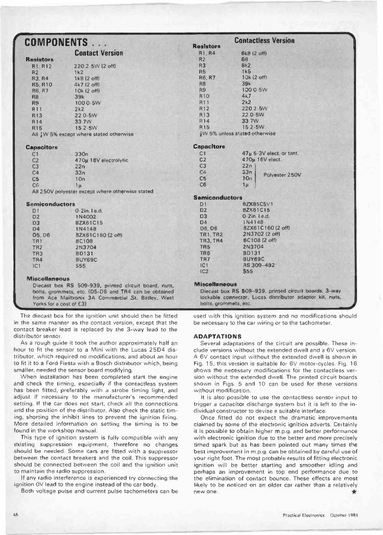
COMPONENTS . . . ResistorsContactless Version
Contact Version R1, R4 6k8 12 offlResistors R2 68
Al. R12 220 2-5W 12 off) R3 8k2R2 1k2 R5 1A5
R3, R4 1k8 (2 off) R6, R7 1Jk (2 off)R5, R10 4k7 (2 off) R8 39kR6, R7 10k (2 off) R9 130 0-5WR8 39k R10 4k7R9 100 0-5W R11 2 c2
R11 2k2 R12 220 2.5WR13 22 0.5W R13 2205WR14 33 7W R14 33 7WR15 15 2-5W R15 15 2.5WAll kW 5% except where stated otherwise
CapacitorsC1 330nC2 470m 16V electrolyticC3 22nC4 33nC5 10nC6
kW 5% unless stated otherwise
CapacitorsCl 47p 6-3VC2 470µC3 22nC4C5 10nC6 lg
elect. or tant.16V elect.
Polyester 250V
All 250V polyester except where otherwise statedSemiconductors
Semiconductors D BZX85C5V1Dl 0-2in. I.e.d. D2 BZX61C15D2 1N4002 D3 0-2in. te.d.D3 BZX61C15 D4 I N4148D4 1N4148 D5, D6 3ZX61C160 (2 off)D5 D6 BZX61C160 (2 off) TR1,TR2 2N3702 (2 off)TR1 BC108 TR3, TR4 8C108 (2 off)TR2 2N3704 TR5 2N3704TR3 BD131 TR6 3D131TR4 BUY69C TR7 BUY69CIC1 555 IC1 RS 309-492
IC2 555Miscellaneous
Diecast box RS 509-939, printed circuit board, nuts,bolts, grommets, etc. (D5-06 and TR4 can be obtainedfrom Ace Mailtronix 3A Commercial St. Batley, WestYorks for a cost of £3)
MiscellaneousDiec.ast box RS 509-939, printed circuit boards, 3 -waylockable connector, Lucas distributor adaptor kit, nuts,bolts, grommets, etc.
The diecast box for the ignition unit should then be fittedin the same manner as the contact version, except that thecontact breaker lead is replaced by the 3 -way lead to thedistributor sensor.
As a rough guide it took the author approximately half anhour to fit the sensor to a Mini with the Lucas 25D4 dis-tributor, which required no modifications, and about an hourto fit it to a Ford Fiesta with a Bosch distributor which, beingsmaller, needed the sensor board modifying.
When installation has been completed start the engineand check the timing, especially if the contactless systemhas been fitted, preferably with a strobe timing light, andadjust if necessary to the manufacturer's recommendedsetting. If the car does not start, check all the connectionsand the position of the distributor. Also check the static tim-ing, shorting the inhibit lines to prevent the ignition firing.More detailed information on setting the timing is to befound in the workshop manual.
This type of ignition system is fully compatible with anyexisting suppression equipment, therefore no changesshould be needed. Some cars are fitted with a suppressorbetween the contact breakers and the coil. This suppressorshould be connected between the coil and the ignition unitto maintain the radio suppression.
If any radio interference is experienced try connecting theignition OV lead to the engine instead of the car body.
Both voltage pulse and current pulse tachometers can be
used with this ignition system and no modifications shouldbe necessary to the car wiring or to the tachometer.
ADAPTATIONSSeveral adaptations of the circuit are possible. These in-
clude versions without the extended dwell and a 6V version.A 6V contact input without the extended dwell is shown inFig. 15; this version is suitable for 6V motor -cycles. Fig. 16shows the necessary modifications for the contactless ver-sion without the extended dwell. The printed circuit boardsshown in Figs. 5 and 10 can be used for these versionswithout modificaton.
It is also possible to use the contactless sensor input totrigger a capacitor discharge system but it is left to the in-dividual constructor to devise a suitable interface.
Once fitted do not expect the dramatic improvementsclaimed by some of the electronic ignition adverts. Certainlyit is possible to obtain higher m.p.g. and better performancewith electronic ignition due to the better and more preciselytimed spark but as has been pointed out many times thebest improvement in m.p.g. can be obtained by careful use ofyour right foot. The most probable results of fitting electronicignition will be better starting and smoother idling andperhaps an improvement in top end performance due tothe elimination of contact bounce. These effects are mostlikely to be noticed on an older car rather than a relativelynew one.
46 Practical Electronics October 198 I
"a Z' Wi.," iiima" a ram "4" 1111..
MI El MIK MI MN If VI MNPIMP IF LIWIF IN= IMmr Mil In\ III. III Nisi atRetail MailOrder Industrial Educational Export
OPEN SIX DAYS A WEEK CALL IN AND SEE FOR YOURSELF
IF /:
LCD DIGITAL MULTIMETRESSPECIAL PURCHASE - LIMITED PERIOD ONLY6220 Reliable 22 range hand held 3' , digit LCD with volt/ohms auto range. unitand range signs 10 amp AC/DC battery warning lower power ohms rangeModel 6110 Also has range hold continuity buzzer and improved accuracy Allmodels high quality rotary operation Resolution 0 1 milli volt 10 -Micro amp0 1 ohm
6220 1030v DC 02/ 10A AC/DC 600v AC 2meg ohm Was £55.95 NOW £42.95
6110 As above plus 20mA AC/DC and improved accuracy Was £85 95
NOW £59.95THIS SPECIAL OFFER IS QUALITY WITH VALUEAlso in stock6200 20/200mA version of 6220 u e no 10 amp)6100 0 2A version of 6110Ii e no 10 ampsI 88ni 16 range with Hfe checker(89m 30 ramie with Hie checker
GLOBAL SPECIALISTS EQUIPMENTGenerators (UK c/p 1-001NCI 1 HZ -100 KHZ sweepable function generator TTL /Sine/Square/Triangle All facilities Mains4001 Ultra Variable Pulse Generator 0 5 HZ -5 MHZ EveryracrIrty Mains £109.00Frequency Counters 1UK c/p 80p1MAX100 100 MHZ Counter Battery operated 8 Digit 30mVtypical Bench portable LED £89.00MAX50 6 Digit 50 MHZ Hand held LED £56.00MAX550 2 range 6 Digit 550 MHZ hand held LEO £97.75PS500 500 MHZ prescaler for MAX50/ 100 £34.50Circuit Powered Logic Probes Pulser and Monitors IUK c/p 65p1LP1 DTL /TTL /CMOS 10 MHZ 100K ohm Pulse Memory£35.5002 MUHL iCmOS 1 5 MHZ 3006 ohm Pulse £19.951P3 NE/TYE/CMOS 50 MHZ 500K ohm Pulse Memory
£55.95LM1 All. 8, 10. 12. 14 6 16 Pin ICS Indicates Pins uniotiDTL/TTL/CMOS/HTL Logic Monitor £33.00DPI Digital Pulse Single shot or 100pps £58.50
cl 13 2
£37 95£49 95£43 50£69.95
HAMEG OSCILLOSCOPESRange or top quality scopes 'or Arnare rr andProfessional (UK c/p 307 £3.00. other£4.00)307 Single trace 10 MHZ 5mV 0 5 micro sec Plus built incomponent tester 6 x 7cm display £158.70(Optional carry case Ma203 Dual 20 MHZ Trig to 30 MHZ 5mV 0 5 micro secs8 x 10cm display (replace model 312) £253.00412-5 Nil 20 MHZ delayed sweep trig 'o 40 MHZ 5mV0 I micro sec 8 x 10cm display £402.50512 Dual 50 MHZ Delayed sweep Single sweep Delayline Trig to 70 MHZ 5mV 0 1 micro sec 8 x 10cm display
£66 7.00Miens 203/412/512 Viewing mod £6 90Component tester 203 412. 5'2 £46.00Carry case (state model) £21.85Optional Probes (All models) XI £8.50: x 0E10 50xi xioE12.95 51oo £16.95
KEITHLEY PROFESSIONALDIGITAL MULTIMETER
Model 130 25 range. Easy to Now and use LCDDMM Size 7 x31 x 15Ranges
DC Volts 200mV-10Q3V 0 5% 130 micro voltAC Volts 200m1/-75CV 1°, 100 micro voltDC current 2mA-10AMP 1-2°, I micro ampAC current 2mA-10AMP 2°, 1 micro ampResistance 200 ohm -20 Meg 0 5°- 0 1 ohm £102.35
SABTRONICS EQUIPMENTNew reuaoie range or DMM s antIrequency computers with thoseextra lacilitres and competitiveprices All battery operated(supplied) Except 5020A mainsOptional mains eliminators available8 01611 COUNTERSO 1 HZ to 10 HZ Res10mV sensitivity to 100 MHZ
(UK c /it El.00)8110A 20 HZ -100 MHZ in 2 ranvs
8610A 20 HZ -600 MHZ in 3 ranges£113.85
9 DIGIT COUNTERS 30mV sensitivity to
1GHZ Resolution 0 1 HZ -10 HZ86108 10 HZ -600 MHZ in 3 ranges
£125.3580008 10 HZ-1GHZ in 3 ranges
£184.00FUNCTION GENERATOR (UK c/p £1.00)with mains adaptor5020A 1 HZ -200 KHZ Sine/Square/Triangle/TTC Freq sweep Lowdistortion £98.90DIGITAL MULTIMETERS Two LCDhand held - one with temperaturerange Also LCD and LED Benchmodels2935A 3'7 digit LCD hand 2A AC/DC20Meg ohm ETC £95.452031A As 2035A with -50' C to 150 C temp range 0 1resolution £109.252010A 3),, Digit LED Auto decimal A. Options Touch A. holdminus 10A AC/DC 20Meg ohm etc Probe for DMM s
£95.45 £14.952015A LCD version of above £109.25 Battery eliminatorsr c/o 2035/37A 65p All others £1.001 state model) £5.69
m111111111:42i,
VARIABLE REGULATEDPOWER SUPPLIESMains operated regulatedsingle metre lUK £1.501241 0/ 12-0/24V 1 amp £35.00154 5-15 volt 3 amp £44.00423 0/ 12.0/24V 3 amp £54.00
SAFGAN PORTABLE OSCILLOSCOPESRange ut low Lust Briar f race Scopes maws operated Made ol UK lcexacting standards Available as 10 MHZ 15 MHZ or 20 MHZ All feature5mV sensitivity. 0.5 micro sec 6 4 x 8cro display IUK c/p £2.50101410 Dual 10 MHZ £194.3501415 Dual 14 MHZ £201.2501420 Dual 20 MHZ £216.20Optional probes available
POWER SUPPLIES 13 8 volt Output regulatedroams operated is £1.001
3 toSamp £15.505to 8 amp £17.95
AMATEUR/CBKOM6 1 5 to 250 MHZ Dip meter6 ranges £38.50SWR9 3-150 MHZ SWR F /S
£9.50SWR50 Twin meter SWR Power1KW max £13.95310 Single meter SWR Powertow £8.95110 SWRiPower iFS-10/ 100W
£11.95171 As 110' Twin meter £14.50175 SWR/FS/AE Match(40 MHZ) £13.80176 As '175 0/5/50 Wattpower £16.95178 As 175 0/10/100W MODScale £19.50HM20 SWR meter Plus 20K /Volt19 range Multimeter £28.95(Note SWR-Power ETC to144/150 MHZ)Just a selection cl a huge rangein stock - send Icr latest listsincluding professional ranges
W01A,parjilin
WOmin on)
LASCAR BENCH MULlIMETER3 Div LCD Made or UK 251anges basic U I
accuracy 2A AC/DC with 0 1 Microamp resolution1KV AC/ 3C 20Meg ohm ETCLM100 £110.00 (UK c/p £1.00Also model LM2001 hand held model 2Meg ohm2A AC/DO ETC £57.70 ILA c p 65p)
TV COLOUR BARPATTERN GENERATORSPAL UHF and VHF ModelsL9C393 VHF 6 pattern £143.75LC6392u UHF 15 pattern £228.85IC6392v VHF 15 pattern £231 15LCG399 VHF, UHF 13 pattern £572 70
LEADER AUDIO RF FMTV GENERATORS
High quality mains operatedequipment (UK c/p£1.501
11916 RF Generator (matches LAG2515 ranges 100 KHZ-100 M-IZ 1303 MPIZharmonics) Int/Ext MOO llXbnrVo/p 1 5°, accuracy £63.5
AUDIOLA626 4 range 20 HZ -20 KHZ Sine/Square 5V o/p Distortion 0 510,.
£73.60LA6120A 5 range 10 HZ -1 MHZ Sine/Square 3V o/p 0 05-0 8% MaxDistortion Switched attenuator
£146.00LA9125 Low distortion (0 02°oversion of LAG120A Plus 'Burst typsignals for Speaker test £273.00
DISCOUNTS Small and large quantity Discounts available for most products for UK and Export Your Enquiries Invited
ALSO STOCKED Range of chassis speakers and kits microphones and public address equipment accessories et
AUDIO ELECTRONICS =e301 EDGWARE ROAD, LONDON, W2 1BN, ENGLAND. TELEPHONE 01 724 3564ALSO AT HENRYS RADIO, 404/406 EDGWARE ROAD, LONDON W2
OPEN SIX DAYS A WEEK CALL IN AND SEE FOR YOURSELF
Order by Post with CHEQUES/ACCESS/VISA or Telephone your order
vir4zzeruE,Send large SAE
120p uK)Schools, Companiesetc. free on request.'
Practical Electronics October 1981 47

FRANK W. HYDE
SUNSPOTS AND THE EARTH'SCLIMATE
There is reason to suppose that there is alink between the cycle of solar activity and theweather. The evidence has been found in themud of Australia. The idea of the Sun's in-fluence on the weather is not new of courseand much effort has been directed towardestablishing a working hypothesis. The Sun'sactivity has scarcely changed over the last500.000.000 years, that is to say, that solaractivity has followed along its present condi-tion of continuous radiation. The change ofintensity of that radiation follows the adventof sunspots and flares. The sunspot activityhas been logged for hundreds of years in greatdetail. Many claims have been made for theeffect of sunspots on motor car sales, stockmarket movements, wars and revolutions,epidemics: in fact in every sphere of worldactivity. However, some years ago there was acooperative investigation between the Elec-tricity Authority and the Meteorological Of-fice which revealed a special cycle of eventswhich correlated with magnetic storms andsunspots. The reason for the investigationarose from the effect of high surges and light-ning strikes on the grid network. A period of174 years with certain significant sub -cycleswas observed.
The recent work by G. E. Williams. who isa geologist with the Exploration Departmentof the Broken Hill Company, Camberwell.Victoria. was undertaken at the FlindersRanges in South Australia. Here thesandstone deposits and siltstone deposits ofsedimentary rocks show a layering whichrelate to climatic conditions and leave a
'signal' which is visible to the eye. Previouslythe periodic effects have been deduced fromstatistical data but in these deposits the layersare visible and show seasonal bands. Layers ofthis nature appear only under special climaticconditions. These layers are called 'varves'.The thickness of these varves indicate the tem-perature at the time they were laid down. The
results shown agree with the 22 year doublesunspot cycles and a 90 year cycle. Recordsare available now for 1760 years of thePrecambrian varves.
Also the magnetic reversals are apparentand thus it seems very likely it will be possibleto examine now some of the problems such asthe 'lack' of nutrino counts which should existaccording to present models. Again, if thevarves are correct the period covered is a con-siderable part of the age of the Solar systemand one in which the Solar clock has beenvery accurate.
A SECOND VISIT TO SATURNThe second Voyager spacecraft pictures of
Saturn and its 17 moons became visible tomankind during August and September. Fiveof the satellites have not till now been morethan blobs of light. The details were seen onthe close approach in the early hours ofAugust 26. Saturn's moon Phoebe will be seenfor the first time. A number of the puzzlingfeatures observed on the first spacecraftflypast will be resolved after the data is
scrutinised. The Cassini division which looksblack from the Earth is in fact filled with manyrings which seem to have polarised crystals orparticles. When the first Voyager passed fromabove, the rings were bright but after passingbelow they became dark. This was discussedat a conference of a small group earlier thisyear. The writer made a suggestion that theanswer might be that there were water icecrystals or particles and also carbon dioxideice. It could be expected that there is polarisa-tion or refraction of sunlight to produce this.As it happened the new controller of opera-tions for this pass was there. Arrangementswere to be made for this suggestion to be ex-amined.
The ring system as a whole was quite unlikeanything that had been imagined. It is un-derstood that there are two satellites whichchange places and it is possible that they wereonce a single satellite; this will now be deter-mined. The programme for the detailed ex-amination of the rings is being carried out bylooking at the rings against the light from thestar Delta Scorpio. This will reveal the struc-tured effect by the way the light is obscured,absorbed or scattered.
The spacecraft will pass closer on this occa-sion to the moons Iapetus, Hyperion, En-celadus, Tethys and Phoebe but will be furtheraway from Titan, Dione, Mimas and Rhea.There are other mysteries to be cleared by therepeat pictures of Iapetus. Why should thissatellite appear with one hemisphere com-pletely dark as though sprayed with soot? En-celadus is covered in ice and smooth like abilliard ball. The others-Mimas, Tethys,Dione and Rhea-are covered in craters withdeep valleys and what may be frozen geysers.The composition of each seems to be different.Some are a mixture of rock and ice thoughTethys has the density of pure ice and Dioneappears to be 40% rock.
More than 18,000 pictures were taken dur-ing this pass and now the spacecraft passes toits new target Uranus. It is hoped that allsystems will remain operational till the fiveyear journey to Uranus is accomplished. Thenwill come the opportunity to see the mysteryplanet Uranus and its environs. This will be in
1986. If at that time the spacecraft is stilloperational it will have as its next target theplanet Neptune, which would be reached by1989.
DYNAMICS EXPLORER MISSIONThe Dynamics Explorer Mission is a twin
spacecraft mission for the explorers toresearch the interaction between themagnetosphere, ionosphere and the atmo-sphere in both high and low altitudes. The pur-pose is to cover areas which have not beenpreviously studied in regard to specialphenomena. The mission is to gather new dataon auroral processes. One of the spacecraftwill detect, when over the equator, powerfulsignals from a transmitter based in the an-tarctic. The signal will be directed into themagnetosphere making changes in the spaceenvironment which will be detected by thespacecraft over the equator. This twin missionis essentially a follow-on mission to theAtmospheric Explorer and the InternationalExplorer programme. Robert Hoffman, one ofthe Project Scientists. said 'The sunlight in-teracts with the upper atmosphere as well asthe lower atmosphere. The interaction ofsunlight with the upper ionospheric region wasstudied in the previous mission together withthe solar wind. The data that was missing wasthe coupling between the magnetosphere, theionosphere and the atmosphere. This gap willbe filled by the new mission.'
The two spacecraft will be used together ac-quiring simultaneous data. For example onespacecraft would be sensing themagnetosphere while the other monitors thestate of the ionosphere and the atmosphereDynamics Explorer A (DE A) will go into anorbit of about 24.875km by 675km and in-clined at 90° so passing over the Earth'spoles. This will ensure that the spacecraft willspend the maximum time in themagnetosphere. The imaging system willmonitor auroral activity. The photographs willenable assessment of the amount of energytransferred from the magnetosphere to theEarth's upper atmosphere to be made.
The second spacecraft DE B will be putinto an orbit 1.300 by 305km. This also will beinclined by 90°. The two Explorers will be inthe same plane. The DE A will carry 6 instru-ment packages and the DE B will carry 9packages.
The antenna systems aboard DE A includetwo long wire units each 328ft. long. This willgive an effective diameter of 656ft. In additionthere will be:- Two I9.3ft. triangular truss booms carryinga loop, search -coil and electric antenna for theplasma wave experiment and a magnetometerto form a 38ft. long span.-A single 4.9ft long S -Band antenna.- Two 13ft. long tubular antennas will bedeployed as part of the plasma experiment.The antenna systems carried by DE B will be:- Six 36ft. long tubular antennas forming aspan of 72ft. around the spacecraft axis aspart of the vector electric field instrument.- A I9.3ft. long triangular truss boom willcarry a magnetometer.- Two 2ft. probes which will sense electrontemperatures and concentrations.-A single 4.9ft. tall S -Band antenna supported by two guy wires of nearly equal length asit sits on top of the spacecraft at launch.
48 Practical Electronics October 1981
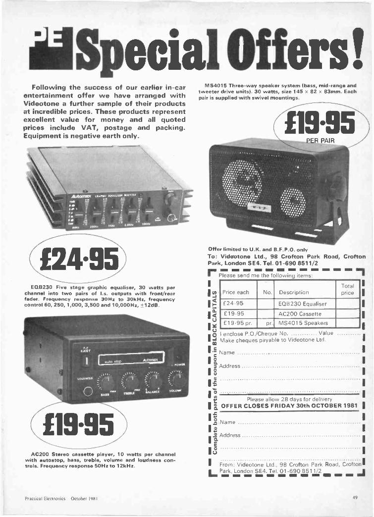
lia Special Offers!Following the success of our earlier in -car
entertainment offer we have arranged withVideotone a further sample of their productsat incredible prices. These products representexcellent value for money and all quotedprices include VAT, postage and packing.Equipment is negative earth only.
fZ4.95EQB230 Five stage graphic equaliser, 30 watts per
channel into two pairs of I.s. outputs with front/rearfader. Frequency response 30Hz to 30kHz, frequencycontrol 60, 250, 1,000, 3,500 and 10,000Hz, 12dB
AC200 Stereo cassette player, 10 watts per channelwith autostop, bass, treble, volume and loudness con-trols. Frequency response 50Hz to 12kHz.
MS4015 Three-way speaker system (bass, mid -range andtweeter drive units). 30 watts, size 145 82 83mm. Eachpair is supplied with swivel mountings.
Offer limited to U.K. and B.F.P.O. onlyTo: Videotone Ltd., 98 Crofton Park Road, CroftonPark, London SEC Tel. 01-690 8511/2..... ttti ttti ..
Please send me the following items:...
Price each No. DescriptionTotalprice
£24.93 EQB230 Equaliser
£19-95 AC200 Cassette
£1995 pr. pr. MS4015 Speakers
I enclose P.O./Cheque No. ValueMake cheques payable to Videotone Ltd.
Name
3 AddressC.)
'r1 Please allow 28 days for delivery
a OFFER CLOSES FRIDAY 30th OCTOBER 1981
I -2.0 NameI
I? AddressI t2'
1
1 From: Videotone Ltd., 98 Crofton Park Road, Crofton'I Park, London SE4. Tel. 01-690 8511/2
ttttta Em Elm - im
Practical Electronics October 1981
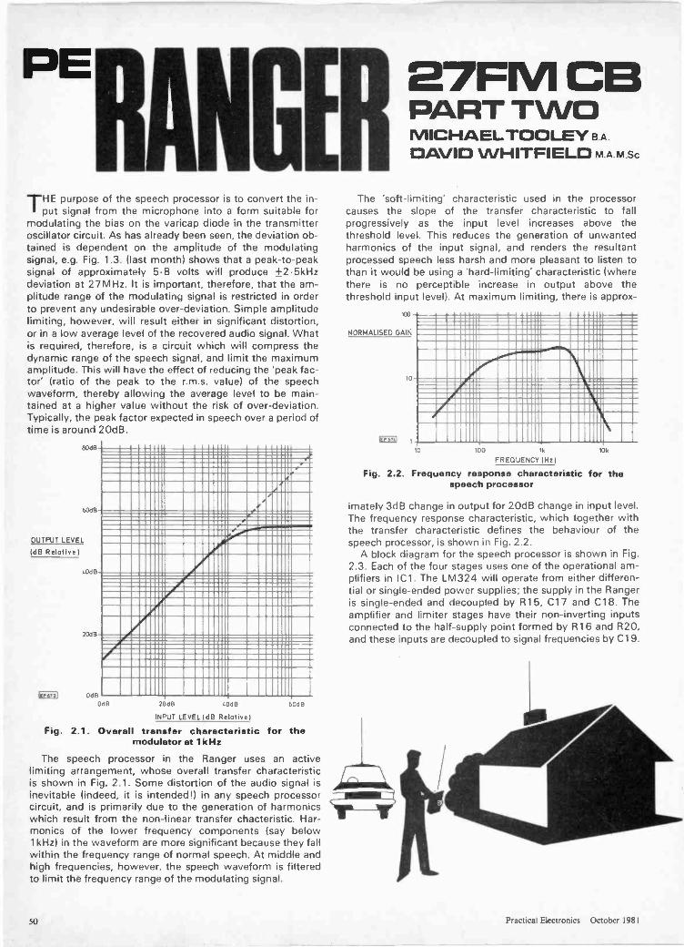
"RANGETHE
purpose of the speech processor is to convert the in-put signal from the microphone into a form suitable for
modulating the bias on the varicap diode in the transmitteroscillator circuit. As has already been seen, the deviation ob-tained is dependent on the amplitude of the modulatingsignal, e.g. Fig. 1.3. (last month) shows that a peak -to -peaksignal of approximately 5.8 volts will produce +2.5kHzdeviation at 27MHz. It is important, therefore, that the am-plitude range of the modulating signal is restricted in orderto prevent any undesirable over -deviation. Simple amplitudelimiting, however, will result either in significant distortion,or in a low average level of the recovered audio signal. Whatis required, therefore, is a circuit which will compress thedynamic range of the speech signal, and limit the maximumamplitude. This will have the effect of reducing the 'peak fac-tor' (ratio of the peak to the r.m.s. value) of the speechwaveform, thereby allowing the average level to be main-tained at a higher value without the risk of over -deviation.Typically, the peak factor expected in speech over a period oftime is around 20dB.
BOdB
60dB
OUTPUT LEVEL
(dB Relative)
40d B
20d8
I
OeB
0dB
Fig. 2.1.
20dB 40dB
INPUT LEVEL (dB Relative)
Overall transfer characteristic for themodulator at 1 kHz
60dB
The speech processor in the Ranger uses an activelimiting arrangement, whose overall transfer characteristicis shown in Fig. 2.1. Some distortion of the audio signal isinevitable (indeed, it is intended!) in any speech processorcircuit, and is primarily due to the generation of harmonicswhich result from the non-linear transfer chacteristic. Har-monics of the lower frequency components (say below1 kHz) in the waveform are more significant because they fallwithin the frequency range of normal speech. At middle andhigh frequencies, however, the speech waveform is filteredto limit the frequency range of the modulating signal.
27FM CBPART TWOMICHAEL TOOLEY B.A.DAVID WHITFIELD M A.M.Sc
The 'soft -limiting' characteristic used in the processorcauses the slope of the transfer characteristic to fallprogressively as the input level increases above thethreshold level. This reduces the generation of unwantedharmonics of the input signal, and renders the resultantprocessed speech less harsh and more pleasant to listen tothan it would be using a 'hard -limiting' characteristic (wherethere is no perceptible increase in output above thethreshold input level). At maximum limiting, there is approx-
100
NORMALISED GAIN
10
lirrnj10 100
FREQUENCY (Hz)
Fig. 2.2. Frequency response characteristic for thespeech processor
10k
imately 3dB change in output for 20dB change in input level.The frequency response characteristic, which together withthe transfer characteristic defines the behaviour of thespeech processor, is shown in Fig. 2.2.
A block diagram for the speech processor is shown in Fig.2.3. Each of the four stages uses one of the operational am-plifiers in IC1. The LM324 will operate from either differen-tial or single -ended power supplies; the supply in the Rangeris single -ended and decoupled by R15, C17 and C18. Theamplifier and limiter stages have their non -inverting inputsconnected to the half -supply point formed by R16 and R20,and these inputs are decoupled to signal frequencies by C19.
50 Practical Electronics October 1981
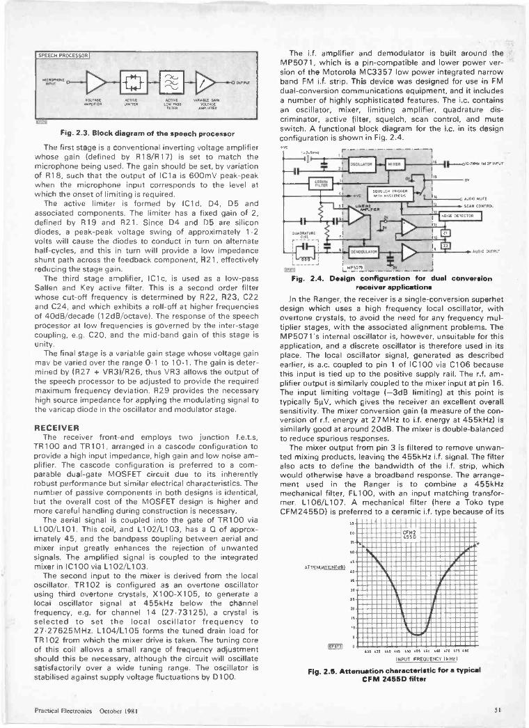
SPEECH PROCESSOR I
MICROPWCOIEPIPUT
VOLTAGEAMPLIFIER
14
ACTIVELIMITER
ACTIVELOW PASS
FILTER
VANMAILE GAINVOLTAGE
A,mL 'FIER
OUTPUT
Fig. 2.3. Block diagram of the speech processor
The first stage is a conventional inverting voltage amplifierwhose gain (defined by R18/R17) is set to match themicrophone being used. The gain should be set, by variationof R18, such that the output of IC1a is 600mV peak -peakwhen the microphone input corresponds to the level atwhich the onset of limiting is required.
The active limiter is formed by IC1d, D4, D5 andassociated components. The limiter has a fixed gain of 2,defined by R19 and R21. Since D4 and D5 are silicondiodes, a peak -peak voltage swing of approximately 1.2volts will cause the diodes to conduct in turn on alternatehalf -cycles, and this in turn will provide a low impedanceshunt path across the feedback component, R21, effectivelyreducing the stage gain.
The third stage amplifier, IC1c, is used as a low-passSallen and Key active filter. This is a second order filterwhose cut-off frequency is determined by R22, R23, C22and C24, and which exhibits a roll -off at higher frequenciesof 40dB/decade (12dB/octave). The response of the speechprocessor at low frequencies is governed by the inter -stagecoupling, e.g. C20, and the mid -band gain of this stage isunity.
The final stage is a variable gain stage whose voltage gainmay be varied over the range 0.1 to 10.1. The gain is deter-mined by (R27 + VR3)/R26, thus VR3 allows the output ofthe speech processor to be adjusted to provide the requiredmaximum frequency deviation. R29 provides the necessaryhigh source impedance for applying the modulating signal tothe varicap diode in the oscillator and modulator stage.
RECEIVERThe receiver front-end employs two junction f.e.t.s,
TR100 and TR101, arranged in a cascode configuration toprovide a high input impedance, high gain and low noise am-plifier. The cascode configuration is preferred to a com-parable dual -gate MOSFET circuit due to its inherentlyrobust performance but similar electrical characteristics. Thenumber of passive components in both designs is identical,but the overall cost of the MOSFET design is higher andmore careful handling during construction is necessary.
The aerial signal is coupled into the gate of TR100 viaL1 00/L101. This coil, and L102/L103, has a Q of approx-imately 45, and the bandpass coupling between aerial andmixer input greatly enhances the rejection of unwantedsignals. The amplified signal is coupled to the integratedmixer in IC100 via L102/L103.
The second input to the mixer is derived from the localoscillator. TR102 is configured as an overtone oscillatorusing third overtone crystals, X100 -X105, to generate alocal oscillator signal at 455kHz below the channelfrequency, e.g. for channel 14 (2743125), a crystal isselected to set the local oscillator frequency to27.27625MHz. L104/L1 05 forms the tuned drain load forTR102 from which the mixer drive is taken. The tuning coreof this coil allows a small range of frequency adjustmentshould this be necessary, although the circuit will oscillatesatisfactorily over a wide tuning range. The oscillator isstabilised against supply voltage fluctuations by D100.
The i.f. amplifier and demodulator is built around theMP5071, which is a pin -compatible and lower power ver-sion of the Motorola MC3357 low power integrated narrowband FM i.f. stnp. This device was designed for use in FMdual -conversion communications equipment, and it includesa number of highly sophisticated features. The i.c. containsan oscillator, mixer, limiting amplifier, quadrature dis-criminator, active filter, squelch, scan control, and muteswitch. A functional block diagram for the i.c. in its designconfiguration is shown in Fig. 2.4.
AU00 MUTE
SCAN CONTROL
NDA=1`MP5071TON
Fig. 2.4. Design configuration for dual conversionreceiver applications
In the Ranger, the receiver is a single -conversion superhetdesign which uses a high frequency local oscillator, withovertone crystals, to avoid the need for any frequency mul-tiplier stages, with the associated alignment problems. TheMP5071's internal oscillator is, however, unsuitable for thisapplication, and a discrete oscillator is therefore used in itsplace. The local oscillator signal, generated as describedearlier, is a.c. coupled to pin 1 of IC100 via C106 becausethis input is tied up to the positive supply rail. The r.f. am-plifier output is similarly coupled to the mixer input at pin 16.The input limiting voltage (-3dB limiting) at this point istypically 5µV, which gives the receiver an excellent overallsensitivity. The mixer conversion gain (a measure of the con-version of r.f. energy at 27MHz to i.f. energy at 455kHz) issimilarly good at around 20dB. The mixer is double -balancedto reduce spurious responses.
The mixer output from pin 3 is filtered to remove unwan-ted mixing products, leaving the 455kHz i.f. signal. The filteralso acts to define the bandwidth of the i.f. strip, whichwould otherwise have a broadband response. The arrange-ment used in the Ranger is to combine a 455kHzmechanical filter, FL100, with an input matching transfor-mer, L106/L107. A mechanical filter (here a Toko typeCFM2455D) is preferred to a ceramic i.f. type because of its
RS
ATTENUATION WS)
NO
SS
SO
LS
40
IS
30
25
20
IS
10
5
=II, 0
CFM24550
430 431 MAO 4LS /SO 455 LSO 461 550 MIS 480
INPUT FREOUENCT (kHz)
Fig. 2.5. Attenuation characteristic for a typicalCFM 2455D filter
Practical Electronics October 1981 51
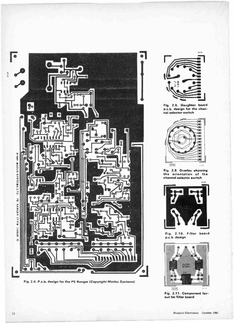
00cncn
cn
cn-4m
rto
-13
m
744
zC,I41I4.3
-n
C
(7)
Fig. 2.6. P.c.b. design for the PE Ranger (Copyright Modus Systems)
E
Fig. 2.8. Daughter boardp.c.b. design for the chan-nel selector switch
Ice is
Fig. 2.9. Overlay showingthe orientation of thechannel selector switch
)
Fig. 2.10. Filter boardp.c.b. design
Enr
Fig. 2.11. Component lay-out for filter board
Practical Electronics October 1981
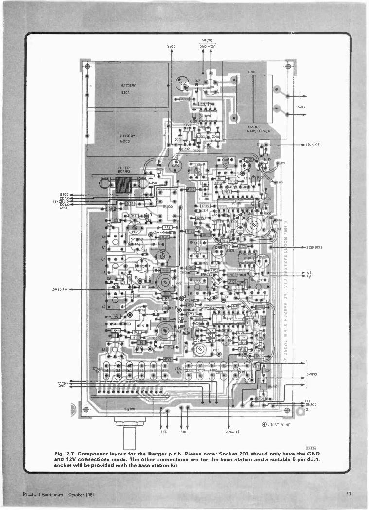
S200COAX
151(20315COAX .4GND
SK20 3)4
PANELOND
BATTERY
5201
BATTERY
B 200
FILTERBOARD 1120?
IY21_16 ir
B L
O c9 C11 4E11
111:111 4Ra iCIO
S' 203
5202
11100
ip-iR2c0}-0-4R2T11-4,
.14A INSTRA4SFORMER
(201.
L100 1
L 2 4011022 11E:31C101
Si< 20. 16
L 3
1t
a
BEAR
1!10-1(41211.-
240V
10.11S X203
0 TEST POINT
(1)
43)
(E,256]
Fig. 2.7. Component layout for the Ranger p.c.b. Please note: Socket 203 should only have the GNDand 12V connections made. The other connections are for the base station and a suitable 6 pin d.i.n.socket will be provided with the base station kit.
Practical Electronics October 1981
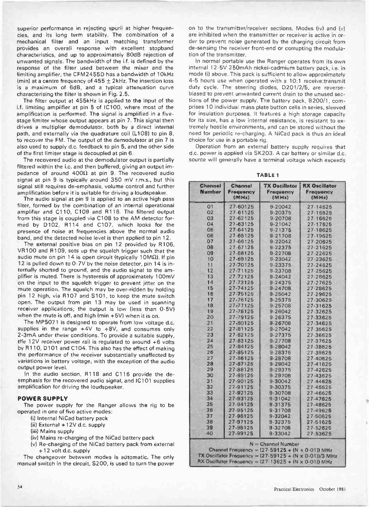
superior performance in rejecting spurii at higher frequen-cies, and its long term stability. The combination of a
mechanical filter and an input matching transformerprovides an overall response with excellent stopbandcharacteristics, and up to approximately 80dB rejection ofunwanted signals. The bandwidth of the i.f. is defined by theresponse of the filter used between the mixer and thelimiting amplifier; the CFM2455D has a bandwidth of 10kHz(min) at a centre frequency of 455 ± 2kHz. The insertion lossis a maximum of 6dB, and a typical attenuation curvecharacterising the filter is shown in Fig. 2.5.
The filter output at 455kHz is applied to the input of thei.f. limiting amplifier at pin 5 of IC100, where most of theamplification is performed. The signal is amplified in a five -stage limiter whose output appears at pin 7. This signal thendrives a multiplier demodulator, both by a direct internalpath, and externally via the quadrature coil (L108) to pin 8,to recover the FM. The output of the demodulator at pin 7 isalso used to supply d.c. feedback to pin 5, and the other sideof the first limiter stage is decoupled at pin 6.
The recovered audio at the demodulator output is partiallyfiltered within the i.c. and then buffered, giving an output im-pedance of around 400n at pin 9. The recovered audiosignal at pin 9 is typically around 350 mV r.m.s., but thissignal still requires de -emphasis, volume control and furtheramplification before it is suitable for driving a loudspeaker.
The audio signal at pin 9 is applied to an active high passfilter, formed by the combination of an internal operationalamplifier and C110, C109 and R116. The filtered outputfrom this stage is coupled via C108 to the AM detector for-med by D102, R114 and C107, which looks for thepresence of noise at frequencies above the normal audioband, and the detected noise level is then applied to pin 12.
The external positive bias on pin 12 provided by R106,VR100 and R109, sets up the squelch trigger such that theaudio mute on pin 14 is open circuit (typically 10mn). If pin12 is pulled down to 0.7V by the noise detector, pin 14 is in-ternally shorted to ground, and the audio signal to the am-plifier is muted. There is hysteresis of approximately 100mVon the input to the squelch trigger to prevent jitter on themute operation. The squelch may be over -ridden by holdingpin 12 high, via R107 and S101, to keep the mute switchopen. The output from pin 13 may be used in scanningreceiver applications; the output is low (less than 0-5V)when the mute is off, and high (min +5V) when it is on.
The MP5071 is designed to operate from low voltage d.c.supplies in the range +4V to +8V, and consumes only2-3mA under these conditions. To provide a suitable supply,the 12V receiver power rail is regulated to around +6 voltsby R110, D101 and C104. This also has the effect of makingthe performance of the receiver substantially unaffected byvariations in battery voltage, with the exception of the audiooutput power level.
In the audio section, R118 and C116 provide the de -emphasis for the recovered audio signal, and IC101 suppliesamplification for driving the loudspeaker.
POWER SUPPLYThe power supply for the Ranger allows the rig to be
operated in one of five active modes:(i) Internal NiCad battery pack(ii) External +12V d.c. supply(iii) Mains supply(iv) Mains re -charging of the NiCad battery pack(v) Re -charging of the NiCad battery pack from external
+12 volt d.c. supplyThe changeover between modes is automatic. The only
manual switch in the circuit, S200, is used to turn the power
on to the transmitter/receiver sections. Modes (iv) and (v)are inhibited when the transmitter or receiver is active in or-der to prevent noise generated by the charging circuit fromde -sensing the receiver front-end or corrupting the modula-tion of the transmitter.
In normal portable use the Ranger operates from its owninternal 12.5V 250mAh nickel -cadmium battery pack, i.e. inmode (i) above. This pack is sufficient to allow approximately4-5 hours use when operated with a 10:1 receive:transmitduty cycle. The steering diodes, D201/2/5, are reverse-
biased to prevent unwanted current drain to the unused sec-tions of the power supply. The battery pack, B200/1, com-prises 10 individua mass plate button cells in series, sleevedfor insulation purposes. It features a high storage capacityfor its size, has a low internal resistance, is resistant to ex-tremely hostile environments, and can be stored without theneed for periodic re -charging. A NiCad pack is thus an idealchoice for use in a portable rig.
Operation from an external battery supply requires thatd.c. power is applied via SK203. A car battery or similar d.c.source will generally have a terminal voltage which exceeds
TABLE 1
ChannelNumber
ChannelFrequency
(MHz)
TX OscillatorFrequency
(MHz)
RX OscillatorFrequency
(MHz)
01 2760125 9.20042 2 7 1462502 27.61125 9.20375 27.1562503 27.62125 9.20708 27.1662504 27.63125 9.21042 27.1762505 27.64125 9.21375 271862506 27.65125 921708 271962507 27.66125 9.22042 272062508 2767125 922375 27.2162509 27.68125 9.22708 27.2262510 27.69125 923042 27.2362511 27.70125 9.23375 27.2462512 27.71125 9 23708 272562513 27 72125 9.24042 272662514 27.73125 9.24375 27.2762515 27.74125 9.24708 27.2862516 2775125 9.25042 27.2962517 2776125 925375 273062518 2777125 9.25708 273162519 27-78125 9.26042 27 3262520 27.79125 926375 27.3362521 27-80125 9.26708 27.3462522 27-81125 9.27042 273562523 27.82125 9.27375 27.3662524 27-83125 9.27708 273762525 27.84125 9.28042 27.3862526 27-85125 928375 273962527 27.86125 9.28708 27.4062528 27.87125 9.29042 27.4162529 27-88125 9.29375 27.4262530 27-89125 929708 274362531 27-90125 930042 27.4462532 27-91125 9.30375 274562533 27.92125 9.30708 27.4662534 27.93125 9.31042 27.4762535 27-94125 9.31375 27.4862536 27-95125 931708 27.4962537 27.96125 9.32042 27.5062538 27-97125 9.32375 27-5162539 27-98125 9-32708 27-5262540 27.99125 933042 27.53625
N = Channel NumberChannel Frequency = (27.59125 + IN x 0.0111 MHz
TX Oscillator Frequency = 127.59125 + IN x 0-0111/3 MHzRX Oscillator Frequency = (27.13625 + (N x 0.01)) MHz
54Practical Electronics October 1981
the 12.5 volts of the internal nickel -cadmium stacks. D201will therefore be forward -biased and D202 will be reverse -biased, causing automatic changeover from the internal bat-teries. With S200 in the 'off position, the battery chargingcircuit formed by IC200 and its associated components willbe active. The 555 timer i.c. in this circuit is configured as anastable multivibrator running at approximately 20kHz. Theastable output is added, via the steering diodes D203 andD204, to the supply voltage to develop a suitable chargingpotential across C204. The NiCad cells in B200/B201 arecharged at almost constant current from this source viaD205 and R202. The maximum charging rate for the250mAh cells specified is 25mA, and 14 hours of chargingare required to restore the charge in a set of fully dischargedcells, i.e. the charge:discharge ratio is 1.4:1. The chargingtime may be extended beyond the fully -charged point by upto 200 per cent without risk of damage to the cells, allowingthe unit to be left on charge overnight to replenish partiallydepleted batteries. The charging circuit is disabled wheneither the receiver or transmitter is active in order to avoidinterference caused by harmonics of the astable output.
CRYSTALSThe frequencies of crystals required for the transmitter
and receiver are listed in Table 1 for the 40 allocated 27MHzCB channels. The transmitter crystals are 9MHz fundamen-tal types designed for use with the circuit loading. Thereceiver crystals are 27MHz third overtone series resonanttypes. By convention, channel 14 is used as the 'callingchannel', and channel 9 is used as the 'emergency channel';they are not working channels and should be reserved fortheir designated uses. A number of alternative channels areuseful for continuing a conversation once contact has beenestablished, usually via channel 14.
CONSTRUCTIONArrange the work surface so that it is well lit and that all
the necessary small tools are available. These should includea soldering iron rated at no more than 25W having aminiature bit, pairs of small long -nosed pliers and cutters, asmall screwdriver, and a sharp knife or scalpel. A magnifyingglass may also be useful for inspecting joints and checkingthat there are no solder bridges between tracks.
The p.c.b. copper foil layout is shown in Fig. 2.6 withcorresponding component layout in Fig. 2.7. The earth plane
Constructors' NoteThe PE Ranger 27FM will only meet the Home Office
specification for UK CB if it is built from a complete kit ofparts from Modus Systems-exactly in accordance with theinstructions given in this series of articles. No responsibilitywill be accepted by Modus Systems for sets which do notmeet the specification due to incorrect assembly or align-ment. The following prices have been specially arranged forPE readers.
The PE Ranger 27FM kit including injection mouldedcase, mains and car input, rechargeable batteries,microphone, helical wave aerial and crystals for two chan-nels, £49.95 plus f 1.40 p&p, plus VAT (C59.05 in:lusive)or £97.00 for a matched pair of transceiver kits with crystalsfor two channels plus £2.80 p&p, plus VAT (£11477inclusive).
Extra sets of crystals are £2.25 for each channel plus 50pp&p (for any quantity), plus VAT.
Extra plastic covered helical wave aerials (overall length50mm) for mobile or base station use, £3.95 each, plus 80pp&p, plus VAT.
Modus Systems Ltd., Dept AP, PO Box 30,Letchworth, Herts. SG6 3DQ V 046 26 74468/76392).
supply rails, and general component layout are quite criticaland constructors should not attempt to use any other layout,p.c.b. design, or construction method since instability willalmost certainly result. Carefully fit the channel selectorswitch, S1/S100, to its daughter p.c.b. (Figs. 2.8 and 2.9),check that it mates correctly and solder the tags. Then fit thein -line right-angle connector which is used to attach thedaughter board to the main transceiver board. Take care notto strain the connector and check that the daughter board isaligned correctly at 90° to the main p.c.b., as shown in Fig.2.7, before soldering it in place. Mount the mains transfor-mer, T200, and solder its connecting tags to the main p.c.b.Having fitted these two components (channel selectorswitch/p.c.b. and mains transformer) it should now be poss-ible to invert the p.c.b. and work on the copper foil sidewithout damaging components fitted to the other side. Theswitch p.c.b. and transformer support the invertedtransceiver p.c.b. clear of the work surface and this con-siderably aids assembly.
It is recommended that the remainder of the componentsbe fitted to the p.c.b. in the following order:
1. r.f. and i.f. inductors and transformers2. i.f. filter and if. chokes3. variable resistors4. variable capacitors5. fixed resistors6. fixed capacitors7. transistors, diodes, bridge rectifier, and i.c.'s8. test points9. links
10. relayNote that the crystals and output filter should not be fitted atthis stage. Instructions for fitting these items are given laterunder the sections dealing respectively with "Initial Testsand Adjustment" and "Alignment". The filter input and out-put pads should, however, be linked together with a shortlength of connecting wire. When fitting the r.f. and i.f.transformers and inductors care should be taken to ensurethat the correct component is fitted in the correct location onthe p.c.b. (part numbers are printed on the metal screeningcans. The transformers should be carefully eased into thep.c.b. observing the pin orientation which is non -reversible.When the bottom of the screening can is flush with the topsurface of the p.c.b. the pins and earth tags may be solderedto the copper foil. Note that L1 has to be modified slightlybefore fitting to the p.c.b. This involves first removing themetal screening can by gently prizing the can away from thebase using the blade of a small screwdriver and pushing thecan upwards. The can may then be discarded and the ferritecup (which is inverted over the coil former assembly) is thenremoved. The remaining coil former, tuning slug, and base isthen mounted on the p.c.b. in a similar manner to that adop-ted for the r.f. and i.f. transformers however, in this case,there are no earth tags to solder. Carefully check the polarityof the electrolytic capacitors and the orientation of thediodes, bridge rectifier, transistors and i.c.'s before fitting,see Fig. 2.7. The use of i.c. sockets is not recommended forthis project since, particularly in the case of IC100, in-stability may result due to the exceptionally high values ofgain involved. Transistor leads should similarly be kept asshort as possible and, in particular, TR3 and TR4 should besoldered so that they are flush with the surface of the p.c.b.Terminal pins of 1mm diameter are used for the test points.These should be carefully push into the p.c.b. using a pair oflong nosed pliers and then soldered into place. The links,which consist of short lengths of insulated connecting wire,should be kept as direct as possible.NEXT MONTH: Testing and Alignment
Practical Electronics October 1981 55

THE LAST WORD IN POCKET PROGRAMMABLE CALCULATORS
* LCD alpha/numeric (dot matrix) scrollingdisplay (86 types).
* Variable input capacity from 32 functionalprogram steps with 88 independentmemories, to 512 steps with 22 memories.
* Memory and program retention whenswitched off.
* Up to 10 pairs unconditional jumps(0010). Manual jump.
* Conditional jumps and count jumps.Indirect addressing.
* Up to 9 subroutines. Nesting possible up to9 levels.
* 50 built-in scientific functions, all usable inprograms.
* PAM (perfect Algebraic Method) with 33brackets at I I levels.
* Ultra high speed calculations.
* Program storage on cassette tape usingoptional FA -1.
* Compatible with FX-501/2P.
* 2 lithium batteries. Approx 660 hours con-tinuous use.
* Battery saving Auto Power Off.
* Only 9.6x71 x 141.2mm. 100g.
CASIO
FX-602P
CI 1.77 CV CIP
(RRP £84.95)
ONLY £74.95
Powerful high speed pocket computer usingBASIC language.
CASIO FX-702P
(RRP £134.95)
ONLY £119.95Available September
LCD scrolling display of alpha/numeric (dot matrix) characters.Input can be varied from 1680 program steps with 26 independentmemories, to 80 program steps with 226 memories. (All retained whenswitched off).Up to 10 programs can be stored (PO to P9). Subroutine: Nested up to 10levels. FORNEXT looping: Nested up to 8 levels.Straightforward program debugging by tracing. Editing by moving cursor.55 built-in scientific aid statistical functions, including regression analysisand correlation coefficient, can be incorporated in programs.Program/data storage on cassette tape via optional FA -2 (available soon).Optional FP -10 mini printer, for program/data print-out, available soon.Two lithium batteries give approx. 200 hours continuous operation, withbattery saving Auto Power Off after approx. 6 minutes non-use.Dimensions: 17x 165 x 82mm (06-1:x3-1-"). Weight: 180g (6.3oz).
JOIN THE KEYBOARD REVOLUTION!
Casiotone Polyphonic Keyboards-Son of success .. The two harpsichords demonstrate theCasiotone's talent for sparkling. crystal clear tones .. Even moreimpressive is the clay (Melody Maker).
CT -202
(RRP £325)
ONLY £27549 instruments ore, 4 octaves. 4 voice memory function withpush button selection. 3 vibrato settings and sustain. Pitchcontrol. CFP jacks. AC only, 3} v 34+v 113/16". 1.5.131bs.
CT -301. NOW ONLY £195CT -401 ONLY £295
MT -30 ONLY £95
INSTANT MUSICIAN!
CASIO VL TONE (VL I)Electronic Musical instrumentand calculator.
C t1,1"ii tit0(1(1'09 951
ONLY £35.95V L I records and plays hack up to 100 notes as a melody.One Key Play or Auto Play of Piano. Violin. Flute. Guitar andFantasy. or create your own unique sounds with A.D.S.R.10 built in Auto Rhythms and Tempo control. LCD digitalreadout of notes and tempo. Also a calculator. Battery poweredwith memory and program retention. Integral amplifier'speaker.Output jack. With Song Book. Dims: 145 1 I 1, 3".
A STAR IS BORN!
The A X 210 is out of this world
CASIOAX -210
(RRP £34.95)
ONLY£29.95
LCD analogue/digital dual display. Dag, alarm playa ).Disielancr, -Greensleeves" or
"My Darling Clementine". Hourly "Big Ben" chime (selectable). Full month calendar display function. Dual time facility (12 or 24 hour). Countdown alarm timer, with repeat. 1/100 second stopwatch. Lap timing.
Delivery normally by return.
ILLUSTRATEDCATALOGUE 20p
NEW LOWER PRICES*
100 metre water resistant watches
With alarm, C/D alarm and stopwatch.
W130
£24.95*W 150C W100
f21.95* £19.95
Time and auto calendar. alarm. hourly chimes. countdown alarmtimer with repeat memory function, stopwatch. Time is always ondisplay. regardless of mode. Stainless steel.
THESE SPACE INVADERS WILL ALARM YOUCasio's most amazing watches ever!
CA90 (left)£19.95*
CA901 (right)£29.95
Time and auto calendar, calculator, alarm, hourly chimes.stopwatch. dual time. DIGITAL SPACE INVADER GAME.
PRICE includes VAT and P&P. Send TEMPUS Dept. PE, FREEPOST,cheques, P.O. or phone your ACCESS 164-167 East Road, Cambridge CB1 1DBor BARCLAYCARD number to: Tel. 0223 312866
56 Practical Electronics October 1981

The age of the robot has arrived with the start of this series describing threeversatile units. Each one employing an electrically driven hydraulic operatingsystem and being capable of real industrial, experimental and domestic tasks.They can be used by amateurs, students and industry to study robotics andassess particular applications of robots. These are not toys but properlydesigned and engineered robcts with arm extensions of up to one metre: fullkits will be available.
Provides, in one programmable unit, a trio backiof drums, bass and a chord instrument. Employinga microprocessor to provide over 3,000 chcrdchanges between approximately 120 chords,makes an ideal project for the penurious soloist.
4/so...FREE ELECTRONC4TMONE (WITH ALL U.K. ISSUES)
ELECTRONICSNOVEMBER ISSUE ON SALE FRIDAY OCTOBER 9th
Practical Electrunics October 1981
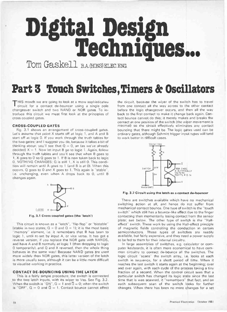
Digital DesignTechniques...
Tom Gaskell B.A.(HONS)RTYC ENG.
Part 3 Touch Switches, Timers & OscillatorsTHIS month we are going to look at a more sophisticateu
circuit for a contact de -bouncer using a single polechangeover switch and two NAND or NOR gates. To in-troduce this circuit we must first look at the principles ofcross coupled gates.
CROSS -COUPLED GATESFig. 3.1 shows an arrangement of cross -coupled gates.
Let's assume that point X starts off at logic 1, and A and Bstart off at logic 0. If you work through the truth tables forthe two gates; and I suggest you do, because it takes a bit ofthinking about; you'll see that Q = 0, an (as we've alreadydecided) X = 1. Now let input B go to logic 1. Again, followthrough the truth tables and you'll see that when B goes to1, X goes to 0 so Q goes to 1. If B is now taken back to logic0, NOTHING CHANGES; Q is still 1, X is still 0. This condi-tion will remain until A goes to 1 (and B is at 0). When thisoccurs, Q goes to 0 and X goes to 1. This again is "stable'',i.e. unchanging, even when A drops back to 0. until Bchanges again.
Fig. 3.1 Cross coupled gates (the latch')
This circuit is known as a "latch", "flip-flop" or "bistable"(stable in two states; Q = 0 and Q = 1); it is the most basic"memory" element, i.e. it remembers that B has been tologic 1, until re -set by input A, or vice versa. It has got areverse version; if you replace the NOR gate with NANDS,and have A and B normally at logic 1 (then dropping to logic0 temporarily), and Q and X reversed, then the whole thingbehaves in the same way! Because NAND gates are usedmore widely than NOR gates, this latter version of the latchis more usually seen, although it can be a little more difficultto visualise working in practice.
CONTACT DE -BOUNCING USING THE LATCHThis is a fairly simple procedure; the switch is connected
to the two latch inputs, with its wiper to Vss. See Fig. 3.2.When the switch is "ON", Q = 1 and 0 = 0; when the switchis "OFF", Q = 0 and Q = 1. Contact bounce cannot affect
the circuit, because the wiper of the switch has to travelfrom one contact all the way across to the other contactbefore the logic changeover occurs, and then all the wayback to the first contact to make it change back again. Con-tact bounce cannot do this; it merely makes and breaks thecontact at one position of the switch (the wiper movement isminimal) so the circuit effectively eliminates any contactbouncing that there might be. The logic gates used can beordinary gates, although Schmitt trigger input types will tendto work better in difficult cases.
50010, 1 Vcc
SWITCH
Vsslor GND
it
FOR CMOS.R IS TYPICALLY10k TO 114FOR TTL R IS 1k
Fig. 3.2 Circuit using the latch as a contact de -bouncer
There are switches available which have no mechanicalswitching action at all, and hence do not suffer frommechanical contact bounce. One type of switch is the "touchswitch" which still has a bounce -like effect due to the fingercontacting then momentarily losing contact from the sensorplate; see below. The other type of switch is the "Hall -effect" switch. These work by using the Hall -effect principleof magnetic fields controlling the conduction in certainsemiconductors. These types of switches are readilyavailable, but fairly expensive, and they need a power supplyto be fed to them for their internal circuitry.
In large assemblies of switches, e.g. calculator or com-puter keyboards, it is often more economical to have com-mon circuitry to contact de -bounce all the switches. Thelogic circuit "scans" the switch array, i.e. looks at eachswitch in sequence, for a short period of time. When itreaches the last switch it starts again at the beginning; overand over again, with each cycle of the process taking a tinyfraction of a second. When the control circuit sees that aparticular switch has changed its logic state since the lasttime that is was scanned, it "remembers" that fact, and oneach subsequent scan of the switch looks for furtherchanges. When there has been no more changes for a set
sx Practical Electronics October 1981
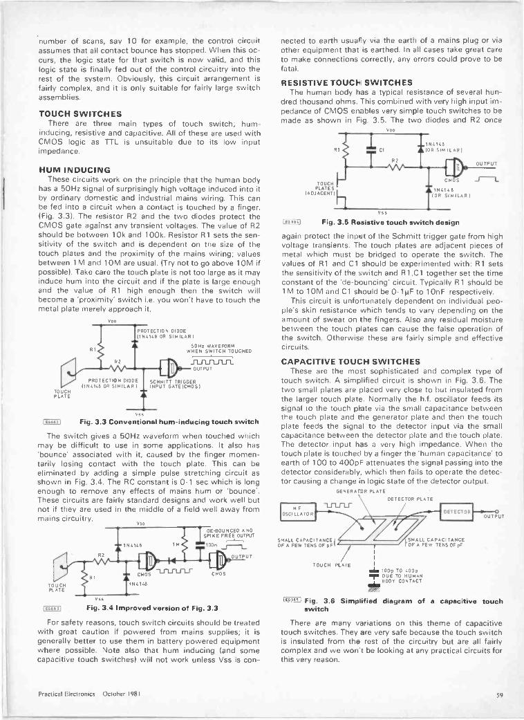
number of scans, say 10 for example, the control circuitassumes that all contact bounce has stopped. When this oc-curs, the logic state for that switch is now valid, and thislogic state is finally fed out of the control circuitry into therest of the system. Obviously, this circuit arrangement isfairly complex, and it is only suitable for fairly large switchassemblies.
TOUCH SWITCHESThere are three main types of touch switch; hum -
inducing, resistive and capacitive. All of these are used withCMOS logic as TTL is unsuitable due to its low inputimpedance.
HUM INDUCINGThese circuits work on the principle that the human body
has a 50Hz signal of surprisingly high voltage induced into itby ordinary domestic and industrial mains wiring. This canbe fed into a circuit when a contact is touched by a finger.(Fig. 3.3). The resistor R2 and the two diodes protect theCMOS gate against any transient voltages. The value of R2should be between 10k and 100k. Resistor R1 sets the sen-sitivity of the switch and is dependent on the size of thetouch plates and the proximity of the mains wiring; valuesbetween 1M and 10M are usual. (Try not to go above 10M ifpossible). Take care the touch plate is not too large as it mayinduce hum into the circuit and if the plate is large enoughand the value of R1 high enough then the switch willbecome a 'proximity' switch i.e. you won't have to touch themetal plate merely approach it.
HOD
PROTECTION DIODE(1N4148 OR SIMILAR)
50Hz WAVEFORMWHEN SWITCH TOUCHED
0 PROTECTION DIODE TRIGGER
OUTPUTT
)1N4140 OR SIMILAR)SCHMITTTRIG
INPUT GATEIc MOsiTOUCHPLATE
I E66621
v,sFig. 3.3 Conventional hum -inducing touch switch
The switch gives a 50Hz waveform when touched whichmay be difficult to use in some applications. It also has'bounce' associated with it, caused by the finger momen-tarily losing contact with the touch plate. This can beeliminated by adding a simple pulse stretching circuit asshown in Fig. 3.4. The RC constant is 0.1 sec which is longenough to remove any effects of mains hum or 'bounce'.These circuits are fairly standard designs and work well butnot if they are used in the middle of a field well away frommains circuitry.
TOUCHPLATE
R2
V ss
VDD
cmosIf
N41413
DE -BOUNCED ANDSPIKE FREE OUTPUT
1 00 n J----1_
C MOS
1E06631 Fig. 3.4 Improved version of Fig. 3.3
OUTPUT
For safety reasons, touch switch circuits should be treatedwith great caution if powered from mains supplies; it isgenerally better to use them in battery powered equipmentwhere possible. Note also that hum inducing (and somecapacitive touch switches) will not work unless Vss is con-
nected to earth usually via the earth of a mains plug or viaother equipment that is earthed. In all cases take great careto make connections correctly, any errors could prove to befatal.
RESISTIVE TOUCI- SWITCHESThe human body has a typical resistance of several hun-
dred thousand ohms. This combined with very high input im-pedance of CMOS enables very simple touch switches to bemade as shown in Fig. 3.5. The two diodes and R2 once
1E00641
Voo
1111111R1
1N4146(OR SIMILAR)
ID:TOUCH
PLATES(ADJACENT)
Vss
C MOS
N2.1413(OR SIMILAR)
Fig. 3.5 Resistive touch switch design
OUTPUT
again protect the input of the Schmitt trigger gate from highvoltage transients. The touch plates are adjacent pieces ofmetal which must be bridged to operate the switch. Thevalues of R1 and Cl should be experimented with: R1 setsthe sensitivity of the switch and R1,C1 together set the timeconstant of the 'de -bouncing' circuit. Typically R1 should be1M to 10M and C1 should be 0.1µF to 10nF respectively.
This circuit is unfo-tunately dependent on individual peo-ple's skin resistance which tends to vary depending on theamount of sweat on the fingers. Also any residual moisturebetween the touch plates can cause the false operation ofthe switch. Otherwise these are fairly simple and effectivecircuits.
CAPACITIVE TOUCH SWITCHESThese are the most sophisticated and complex type of
touch switch. A simplified circuit is shown in Fig. 3.6. Thetwo small plates are placed very close to but insulated fromthe larger touch plate. Normally the h.f. oscillator feeds itssignal to the touch plate via the small capacitance betweenthe touch plate and the generator plate and then the touchplate feeds the signal to the detector input via the smallcapacitance between the detector plate and the touch plate.The detector input has a very high impedance. When thetouch plate is touched by a finger the 'human capacitance' toearth of 100 to 400pF attenuates the signal passing into thedetector considerably, which then fails to operate the detec-tor causing a change in logic state of the detector output.
GENERATOR PLATE
DETECTOR PLATE
H FOSCI LLATOR
SMALL CAPACITANCE!OF A :=EW TENS OF pF
TOUCH PLATE
DETECTOR
/SMALL CAPACITANCEOF A FEW TENS OF pF
1
olio 100p TO 400pIlor DUE TO HUMAN
BODY CONTACT
OUTPUT
1666" Fig. 3.8 Simplified diagram of a capacitive touchswitch
There are many variations on this theme of capacitivetouch switches. They are very safe because the touch switchis insulated from the rest of the circuitry but are all fairlycomplex and we won't be looking at any practical circuits forthis very reason.
Practical Electronics October 1981 59
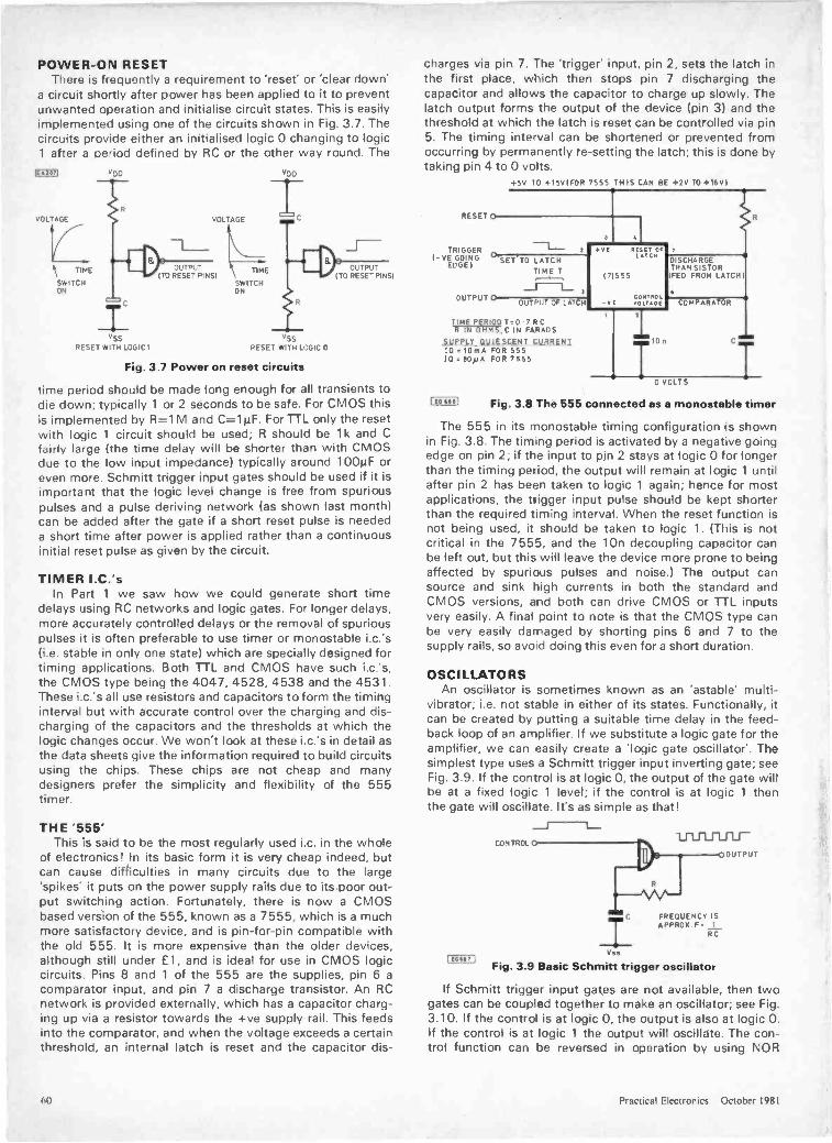
POWER -ON RESETThere is frequently a requirement to 'reset' or 'clear down'
a circuit shortly after power has been applied to it to preventunwanted operation and initialise circuit states. This is easilyimplemented using one of the circuits shown in Fig. 3.7. Thecircuits provide either an initialised logic 0 changing to logic1 after a period defined by RC or the other way round. The
MA
VOLTAGE
TIME
SWITCHON
VD0 VDD
VOLTAGE
OUTPUT I\ TIMEITO RESET PINS)
SWITCHON
Vss VSSRESET WITH LOGIC I RESET WITH LOGIC
OUTPUTITO RESET PINS)
Fig. 3.7 Power on reset circuits
time period should be made long enough for all transients todie down; typically 1 or 2 seconds to be safe. For CMOS thisis implemented by R=1 M and C=1µF. For TTL only the resetwith logic 1 circuit should be used; R should be 1k and Cfairly large (the time delay will be shorter than with CMOSdue to the low input impedance) typically around 100µF oreven more. Schmitt trigger input gates should be used if it isimportant that the logic level change is free from spuriouspulses and a pulse deriving network (as shown last month)can be added after the gate if a short reset pulse is neededa short time after power is applied rather than a continuousinitial reset pulse as given by the circuit.
TIMER I.C.'sIn Part 1 we saw how we could generate short time
delays using RC networks and logic gates. For longer delays,more accurately controlled delays or the removal of spuriouspulses it is often preferable to use timer or monostable i.c.'s(i.e. stable in only one state) which are specially designed fortiming applications. Both TTL and CMOS have such i.c.'s,the CMOS type being the 4047, 4528, 4538 and the 4531.These i.c.'s all use resistors and capacitors to form the timinginterval but with accurate control over the charging and dis-charging of the capacitors and the thresholds at which thelogic changes occur. We won't look at these i.c.'s in detail asthe data sheets give the information required to build circuitsusing the chips. These chips are not cheap and manydesigners prefer the simplicity and flexibility of the 555timer.
THE '555'This is said to be the most regularly used i.c. in the whole
of electronics! In its basic form it is very cheap indeed, butcan cause difficulties in many circuits due to the large'spikes' it puts on the power supply rails due to its poor out-put switching action. Fortunately, there is now a CMOSbased version of the 555, known as a 7555, which is a muchmore satisfactory device, and is pin -for -pin compatible withthe old 555. It is more expensive than the older devices,although still under £1, and is ideal for use in CMOS logiccircuits. Pins 8 and 1 of the 555 are the supplies, pin 6 acomparator input, and pin 7 a discharge transistor. An RCnetwork is provided externally, which has a capacitor charg-ing up via a resistor towards the +ve supply rail. This feedsinto the comparator, and when the voltage exceeds a certainthreshold, an internal latch is reset and the capacitor dis-
charges via pin 7. The 'trigger' input, pin 2, sets the latch inthe first place, which then stops pin 7 discharging thecapacitor and allows the capacitor to charge up slowly. Thelatch output forms the output of the device (pin 3) and thethreshold at which the latch is reset can be controlled via pin5. The timing interval can be shortened or prevented fromoccurring by permanently re -setting the latch; this is done bytaking pin 4 to 0 volts.
+5V TO +15VIFOR 7555 THIS CAN BE +2V TO +11/1
RESET 0
TRIGGERI- YE GOING
EDGE I
OUTPUT 0
SET.TO LATCHTIME T
OUTPUT OF LATCH
TtrIVIP,OV1191Q Ts07RCHMS, C IN FARADS
SUPPLY QUIESCENT CURRENT10 .10mA FOR 55510 :BONA FOR 7555
E RE 17 OE 7L TEN
DISCHARGETRANSISTOR
171555 IFED FROM LATCH
6CONTROL
-VE VOLTAGE COMPARATOR
10n
0 VOLTS
I om) Fig. 3.8 The 555 connected as a monostable timer
The 555 in its monostable timing configuration is shownin Fig. 3.8. The timing period is activated by a negative goingedge on pin 2; if the input to pin 2 stays at logic 0 for longerthan the timing period, the output will remain at logic 1 untilafter pin 2 has been taken to logic 1 again; hence for mostapplications, the trigger input pulse should be kept shorterthan the required timing interval. When the reset function isnot being used, it should be taken to logic 1. (This is notcritical in the 7555, and the 10n decoupling capacitor canbe left out, but this will leave the device more prone to beingaffected by spurious pulses and noise.) The output cansource and sink high currents in both the standard andCMOS versions, and both can drive CMOS or TTL inputsvery easily. A final point to note is that the CMOS type canbe very easily damaged by shorting pins 6 and 7 to thesupply rails, so avoid doing this even for a short duration.
OSCILLATORSAn oscillator is sometimes known as an 'astable' multi -
vibrator; i.e. not stable in either of its states. Functionally, itcan be created by putting a suitable time delay in the feed-back loop of an amplifier. If we substitute a logic gate for theamplifier, we can easily create a 'logic gate oscillator'. Thesimplest type uses a Schmitt trigger input inverting gate; seeFig. 3.9. If the control is at logic 0, the output of the gate willbe at a fixed logic 1 level; if the control is at logic 1 thenthe gate will oscillate. It's as simple as that!
CONTROL
xC
Vss
FREQUENCY ISAPPROX.F 1
RC
Fig. 3.9 Basic Schmitt trigger oscillator
If Schmitt trigger input gates are not available, then twogates can be coupled together to make an oscillator; see Fig.3.10. If the control is at logic 0, the output is also at logic 0.If the control is at logic 1 the output will oscillate. The con-trol function can be reversed in operation by using NOR
OUTPUT
I IOW 1
(1() Practical Electronics October 1981
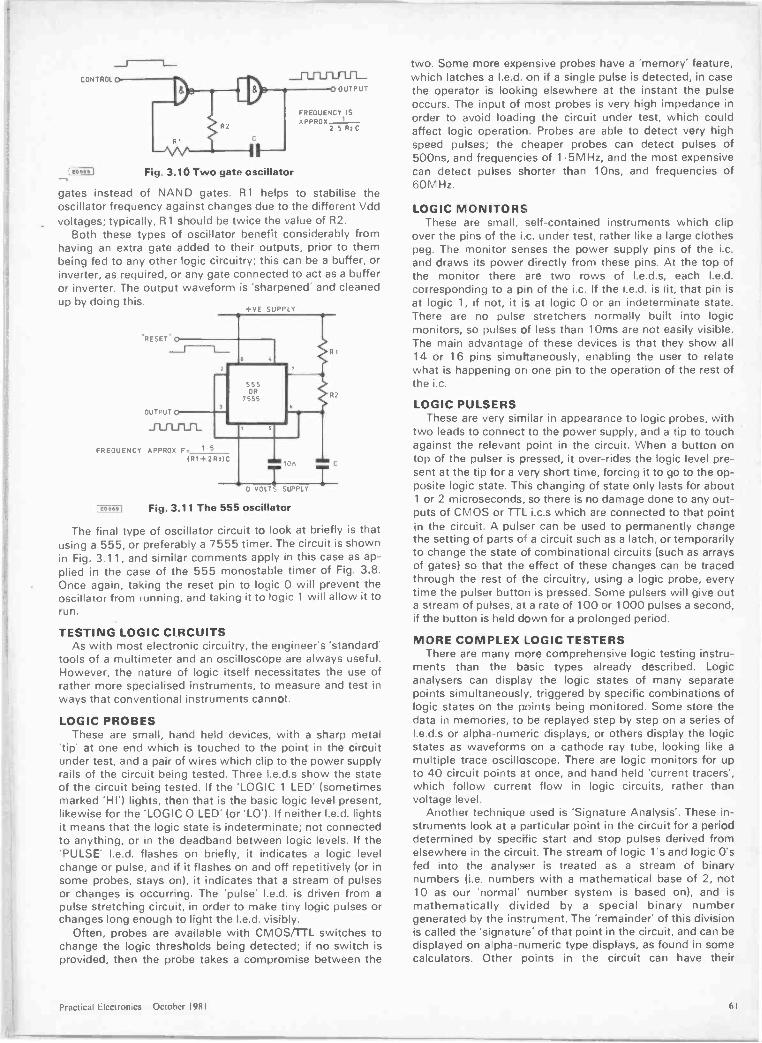
CONTROL
Fig. 3.10 Two gate oscillator
OUTPUT
FREQUENCY ISAPPROX 1
25 Rt C
gates instead of NAND gates. R1 helps to stabilise theoscillator frequency against changes due to the different Vddvoltages; typically, R1 should be twice the value of R2.
Both these types of oscillator benefit considerably fromhaving an extra gate added to their outputs, prior to thembeing fed to any other logic circuitry; this can be a buffer, orinverter, as required, or any gate connected to act as a bufferor inverter. The output waveform is 'sharpened' and cleanedup by doing this.
*RESET -
OUTPUT
FREQUENCY APPROX F. 15
(06691
IR1+2RtIC
+VE SUPPLY
555OR
7555
lOn
0 VOLT SUPPLY
Fig. 3.11 The 555 oscillator
RI
FI2
The final type of oscillator circuit to look at briefly is thatusing a 555, or preferably a 7555 timer. The circuit is shownin Fig. 3.11, and similar comments apply in this case as ap-plied in the case of the 555 monostable timer of Fig. 3.8.Once again, taking the reset pin to logic 0 will prevent theoscillator from running, and taking it to logic 1 will allow it torun.
TESTING LOGIC CIRCUITSAs with most electronic circuitry, the engineer's 'standard'
tools of a multimeter and an oscilloscope are always useful.However, the nature of logic itself necessitates :he use ofrather more specialised instruments, to measure and test inways that conventional instruments cannot.
LOGIC PROBESThese are small, hand held devices, with a sharp metal
'tip' at one end which is touched to the point in the circuitunder test, and a pair of wires which clip to the power supplyrails of the circuit being tested. Three I.e.d.s show the stateof the circuit being tested. If the 'LOGIC 1 LED' (sometimesmarked 'HI') lights, then that is the basic logic level present,likewise for the 'LOGIC 0 LED' (or 'LO'). If neither I.e.d. lightsit means that the logic state is indeterminate; not connectedto anything, or in the deadband between logic levels. If the'PULSE' I.e.d. flashes on briefly, it indicates a logic levelchange or pulse, and if it flashes on and off repetitively (or insome probes, stays on), it indicates that a stream of pulsesor changes is occurring. The 'pulse' I.e.d. is driven from apulse stretching circuit, in order to make tiny logic pulses orchanges long enough to light the I.e.d. visibly.
Often, probes are available with CMOS/TTL switches tochange the logic thresholds being detected; if no switch isprovided, then the probe takes a compromise between the
two. Some more expensive probes have a 'memory' feature,which latches a I.e.d. on if a single pulse is detected, in casethe operator is looking elsewhere at the instant the pulseoccurs. The input of most probes is very high impedance inorder to avoid loading the circuit under test, which couldaffect logic operation. Probes are able to detect very highspeed pulses; the cheaper probes can detect pulses of500ns, and frequencies of 1.5MHz, and the most expensivecan detect pulses snorter than 1 Ons, and frequencies of60M Hz.
LOGIC MONITORSThese are small, self-contained instruments which clip
over the pins of the i.e. under test, rather like a large clothespeg. The monitor senses the power supply pins of the i.c.and draws its power directly from these pins. At the top ofthe monitor there are two rows of I.e.d.s, each I.e.d.corresponding to a pin of the i.c. If the I.e.d. is lit, that pin isat logic 1, if not, it is at logic 0 or an indeterminate state.There are no pulse stretchers normally built into logicmonitors, so pulses of less than 10ms are not easily visible.The main advantage of these devices is that they show all14 or 16 pins simultaneously, enabling the user to relatewhat is happening on one pin to the operation of the rest ofthe i.c.
LOGIC PULSERSThese are very similar in appearance to logic probes, with
two leads to connect to the power supply, and a tip to touchagainst the relevant point in the circuit. When a button ontop of the pulser is pressed, it over -rides the logic level pre-sent at the tip for a very short time, forcing it to go to the op-posite logic state. This changing of state only lasts for about1 or 2 microseconds, so there is no damage done to any out-puts of CMOS or TTL i.c.s which are connected to that pointin the circuit. A pulser can be used to permanently changethe setting of parts o' a circuit such as a latch, or temporarilyto change the state of combinational circuits (such as arraysof gates) so that the effect of these changes can be tracedthrough the rest of the circuitry, using a logic probe, everytime the pulser button is pressed. Some pulsers will give outa stream of pulses, at a rate of 100 or 1000 pulses a second,if the button is held down for a prolonged period.
MORE COMPLEX LOGIC TESTERSThere are many more comprehensive logic testing instru-
ments than the basic types already described. Logicanalysers can display the logic states of many separatepoints simultaneously, triggered by specific combinations oflogic states on the points being monitored. Some store thedata in memories, to be replayed step by step on a series ofI.e d.s or alpha -numeric displays, or others display the logicstates as waveforms on a cathode ray tube, looking like amultiple trace oscilloscope. There are logic monitors for upto 40 circuit points at once, and hand held 'current tracers',which follow current flow in logic circuits, rather thanvoltage level.
Another technique used is 'Signature Analysis'. These in-struments look at a particular point in the circuit for a perioddetermined by specific start and stop pulses derived fromelsewhere in the circuit. The stream of logic l's and logic 0'sfed into the analyser is treated as a stream of binarynumbers (i.e. numbers with a mathematical base of 2, not10 as our 'normal' number system is based on, and ismathematically divided by a special binary numbergenerated by the ins:rument. The 'remainder' of this divisionis called the 'signature' of that point in the circuit, and can bedisplayed on a pha-numeric type displays, as found in somecalculators. Other points in the circuit can have their
Practical Electronics October 1981 61
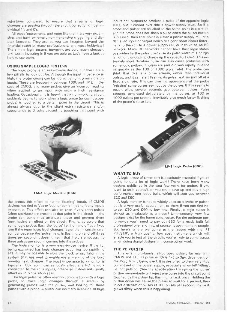
signatures compared, to ensure that streams of logicchanges are passing through the circuit correctly not just in-dividual l's and 0's.
All these instruments, and more like them, are very expen-sive, and have extremely comprehensive triggering and dis-play functions. They are, as you can imagine, beyond thefinancial reach of many professionals, and most hobbyists!The simple logic testers, however, are very much cheaper,and worth investing in if you are able to. Let's have a look athow to use them.
USING SIMPLE LOGIC TESTERSThe logic probe is an easy -to -use device, but these are a
few pitfalls to look out for. Although the input impedance ishigh, the probe circuit can be fooled by pull-up resistors oninputs. These are frequently between 100k and limn in thecase of CMOS, and many probes give an incorrect readingwhen applied to an input with such a high resistanceloading. Occasionally, it is found that a non -working circuitsuddenly begins to work when a logic probe (or oscilloscopeprobe) is touched to a certain point in the circuit! This isalmost always due to the slight extra resistance and/orcapacitance to 0 volts caused by touching that point with
LM -1 Logic Monitor (GSC)
the probe; this often points to 'floating' inputs of CMOSdevices not tied to Vss or Vdd, or sometimes to faulty inputsor outputs. This effect can also be seen if very short pulses(often spurious) are present at that point in the circuit - theprobe can sometimes attenuate these and prevent themfrom having an effect on the circuit. Finally, be aware thatsome logic probes flash the 'pulse' I.e.d. on and off at a fixedrate if the input logic level changes faster than a certain rate;so, just because the 'pulse' I.e.d. is flashing on and off threetimes per second, it doesn't mean that there are necessarilythree pulses per second coming into the probes!
The logic monitor is a very easy -to -use device. If the i.c.being examined has logic changes occurring too rapidly tosee, it may be possible to slow the 'clock' or oscillator in thesystem (if it has one) to enable easier viewing of tie logicmonitor I.e.d. changes. The input impedance to a monitor istypically 100k, so it can seriously affect any RC networkconnected to the i.c.'s inputs; otherwise it does not usuallyaffect an i.c.'s operation at all.
The logic pulser is often used in combination with a logicprobe, to trace logic changes through a system bygenerating pulses with the pulser, and looking for thosepulses with a probe. A pulser can normally over -ride all logic
inputs and outputs to produce a pulse of the opposite logicstate, but it cannot over -ride a power supply level. So if aprobe and pulser are touched to the same point in a circuit,and the probe does not show a pulse when the pulser buttonis pressed, then that point is either a power supply rail, or adamaged input or output which has gone short circuit (inter-nally to the i.c.) to a power supply rail, or it could be an RCnetwork. Many RC networks cannot have their logic statesover-riden by the pulser, because its pulse width of 1 or 2µsis not long enough to charge up the capacitors used. This ex-tremely short duration pulse can also cause problems withsome logic probes, if pulses are sent out very rapidly (but notas quickly as the 100 or 1000 p.p.s. rate. The probe canthink that this is a pulse stream, rather than individualpulses, and it can start flashing its pulse I.e.d. on and off at afixed slow rate. This can give the appearance of the probe'missing' some pulses sent out by the pulser. If this seems tooccur, allow several seconds gap between pulses. Pulsestreams generated deliberately by the pulser, at 100 or1000 pulses per second, inevitably give much faster flashingof the probe's pulse I.e.d.
LP -2 Logic Probe (GSC)
WHAT TO BUYA logic probe of some sort is absolutely essential if you're
going to do a lot of logic work! There have been manydesigns published in the past few years for probes, if youwant to do it yourself, or you could save up and buy a highperformance one ready built, which will cost you between£20 and £60.
A logic monitor is not as widely used as a probe or pulser,but is a very useful supplement to them if you can find be-tween £30 and £40 to buy one. Finally, a logic pulser isalmost as invaluable as a probe! Unfortunately, very fewdesigns exist for the home constructor. For the optimum per-formance you'll need to pay out £50 for a ready built fullprofessional one, and this, of course, is beyond many people.So, here's where we come to the rescue with the 'PEPULSER', a high quality, low cost instrument which willenable you to test all the circuits you're likely to come acrosswhen doing digital designs and construction work!
THE PE PULSERThis is a multi -family, all-purpose pulser, for use with
CMOS and TTL. Its pulse width is 1.5 to 3µs, dependent onthe logic family being used. It is designed to draw very littlecurrent out of the power supply, especially when left 'idling',i.e. not pulsing. (See the specification.) Pressing the 'pulse'button momentarily will inject one pulse into the circuit pointtouched by the pulser tip, flashing its I.e.d. once. Holding thebutton down will cause the pulser to wait for a second, theninject a stream of pulses at 100 pulses per second; the I.e.d.glows dimly when this is happening.
62 Practical Electronics October 1981
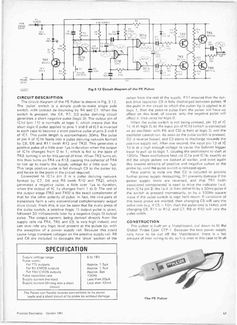
+VEPROBELEAD
DI1N4002
O 01
PROBEI 0LEAD
[89670 I
ICIPIN 14
RED
TR1BC184L
IC IPIN 7
+VE SUPPLY
1N4146
IC1d4093
DV
Fig 3.12 Circuit diagram of the PE Pulser
CIRCUIT DESCRIPTIONThe circuit diagram of the PE Pulser is shown in Fig. 3.12.
The 'pulse' switch is a simple push -to -make single poleswitch, with contact de -bouncing by R4 and C1. When theswitch is pressed, the C4, R7, D3 pulse deriving circuitgenerates a short negative pulse (logic 0). The output pin ofICI d (pin 11) is normally at logic 1, which means that theshort logic 0 pulse applied to pins 1 and 6 of IC1 is invertedin each case to become a short positive pulse at pins 3 and 4of IC1. This pulse length is approximately 30ms. The pulseat pin 4 of ICI b feeds into a pulse deriving network formedby C8, D5 and R11 (with R12 and TR3). This generates apositive pulse of a little over 1p.s in duration when the outputof ICI b changes from 0 to 1, which is fed to the base ofTR3, turning it on for this period of time. When TR3 turns on,this then turns on TR4 via R13, causing the collector of TR4to rise up to nearly the supply voltage for a little over 1ps.This large positive pulse is fed through C9 to the pulser tip,and hence to the point in the circuit required.
Connected to IC1a pin 3 is a pulse deriving networkformed by C7, D4 and R9 (with R10 and TR2), whichgenerates a negative pulse, a little over 1ps in duration,when the output of IC 1a changes from 1 to 0. The rest ofthe output stage (TR2 and TR5) is the exact complement ofthat for the other polarity of pulse. In fact, the two pairs oftransistors form a very conventional complementary outputdrive circuit. From this, it can be seen that for every press ofthe pulse switch, a positive (logic 1) output pulse is given,followed 30 milliseconds later by a negative (logic 0) outputpulse. The output current, being derived directly from thesupply rails via TR4, TR5 and C9, is very high indeed, andcan over -ride any logic level present at the pulser tip, withthe exception of a power supply rail. Because this couldcause large transient voltages on the positive supply rail, R8and C6 are included to decouple the 'drive' section of the
SPECIFICATIONSupply voltage range 5 to 18VPulse width:
For TTL outputs Approx. 1.5pFor 5V CMOS outputs Approx. 1.51.1sFor 15V CMOS outputs Approx. 3t.ts
Pulse repetition rate 100HzSupply current (no load) : ess than 20µASupply current (driving into a short
circuit)Less thar 10mA
The Pulser can handle reverse connections to its powerleads and a short circuit of its probe tip without damage.
1210I" 5k611.4146
C622p25V
CB 811
33p =C5 10k
11..41413
TR2BC214L
TR3BC1B..L
TR4BC 214L
R171k5
TR5BC 18 CL
PUTLIERP
pulser from the rest of the supply. R17 ensures that the out-put drive capacitor C9 is fully discharged between pulses. Ifthe joint in the circuit to which the pulser tip is applied is atlogic 1, then the positive pulse from the pulser will have noeffect on this level, of course, only the negative pulse willaffect it. Vice versa for logic 0.
When the pulse switch is not being pressed, pin 10 of IC1c, is at logic 0, so the input pin of IC1 d (which is connectedas an oscillator with R6 and C5) is held at logic 0, and theoscillator cannot run. As soon as the pulse switch is pressed,D2 is reverse biased, and C3 starts to discharge towards thepositive supply rail. After one second, the input pin 13 of IC1 d is at a high enough voltage to cause the Schmitt triggerinput to pull up to logic 1, causing the oscillations to start at100Hz. These oscillations feed via ICI a and ICI b, exactly asdid the single pulses we looked at earlier, and once againthis creates streams of positive and negative pulses at theprobe tip, until the pulse switch is released again.
Final points to note are that C2 is included to providefurther power supply decoupling, D1 prevents damage if thepower supply leads are reversed, and that TR1 (withassociated comoonents) is used to drive the indicator I.e.d.from IC1a pin 3; the I.e.d. is then either lit by a 30ms pulse ifthe switch is pressed momentarily, or by a 100Hz squarewave if the pulse switch is kept held down. If variations ofthis basic probe are wanted, then changing C5 will vary thepulse rate (e.g. if C5 = 1 On, then the pulse rate is 1kHz), andchanging C8, R11 or R12, and C7, R9 or R10 will vary thepulse width.
CONSTRUCTIONThe pulser is built on a Matchboard, cut down to fit the
Global 'Probe Case' CTP-1. Because the two power supplyrails have to be cut off the Matchboard, there is a fairamount of inter -wiring to do, so it is wise in this case to fit all
The PE Pulsar
Practical Electronics October 1981 63
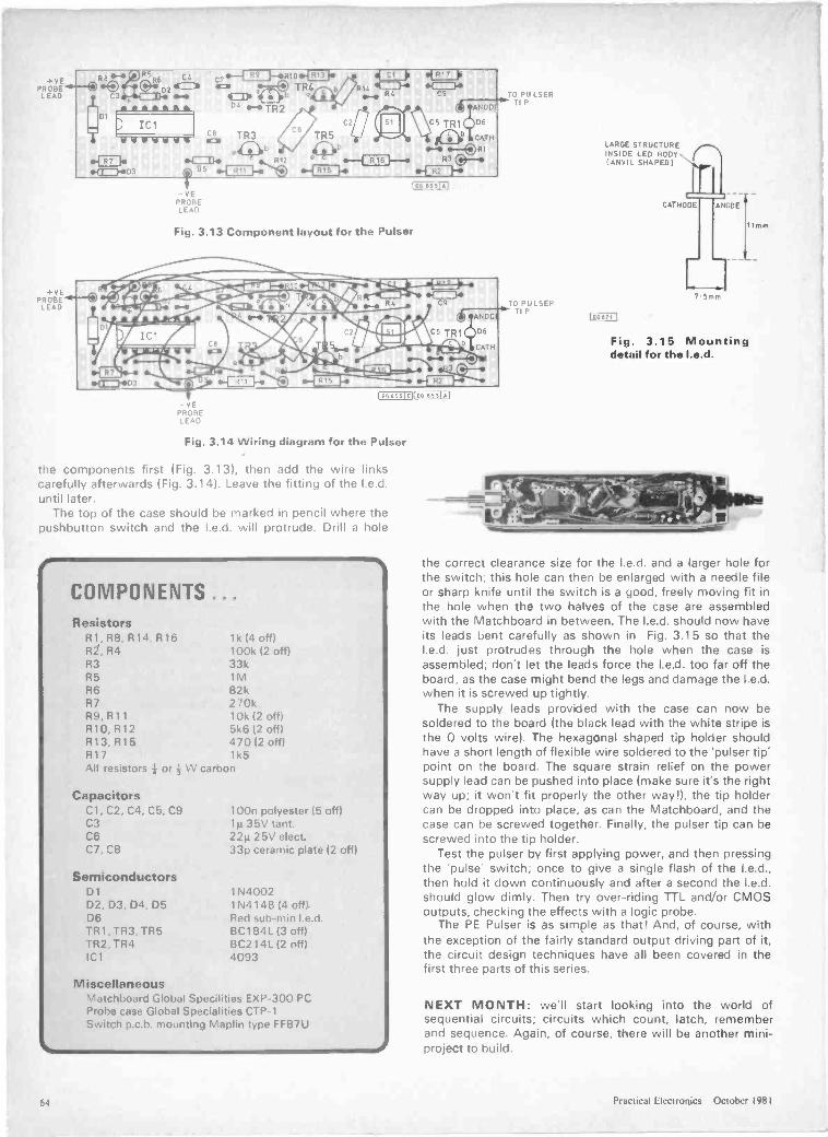
P
Ai
Fig. 3.13 Component layout for the Pulser
-YEPROBE
LEAD
Fig. 3.14 Wiring diagram for the Pulser
the components first (Fig. 3.13), then add the wire linkscarefully afterwards (Fig. 3.14). Leave the fitting of the I.e.d.until later.
The top of the case should be marked in pencil where thepushbutton switch and the I.e.d. will protrude. Drill a hole
COMPONENTS ...Resistors
R1, R8. R14, R16 1k (4 off)R2, R4 100k (2 off)R3 33kR5 1MR6 82kR7 270kR9, R11 10k (2 off)R10,R12 5k6 (2 off)R13, R15 470 (2 off)R17 1k5All resistors I or W carbon
CapacitorsC1, C2, C4, C5, C9 100n polyester (5 offlC3 11.135V tant.C6 22µ 25V elect.C7, C8 33p ceramic plate (2 offl
SemiconductorsD1 1N4002D2, D3. D4, D5 1N4148 (4 off)D6 Red sub -min I.e.d.TR1, TR3, TR5 BC184L (3 offTR2, TR4 BC214L (2 off)ICI 4093
MiscellaneousMatchboard Global Specilities EXP-300 PCProbe case Global Specialities CTP-1Switch p.c.b. mounting Maplin type FF87U
0 PU LSERTI P
ANOD
TR1l 06
413111 CAT H
:3 C
LARGE STRUCTUREINSIDE LED BODYI ANVIL SHAPED)
CATHODE ANODE
7 5mm
Ilmm
Fig. 3.15 Mountingdetail for the I.e.d.
the correct clearance size for the I.e.d. and a larger hole forthe switch; this hole can then be enlarged with a needle fileor sharp knife until the switch is a good, freely moving fit inthe hole when the two halves of the case are assembledwith the Matchboard in between. The I.e.d. should now haveits leads bent carefully as shown in Fig. 3.15 so that theI.e.d. just protrudes through the hole when the case isassembled; don't let the leads force the I.e.d. too far off theboard, as the case might bend the legs and damage the I.e.d.when it is screwed up tightly.
The supply leads provided with the case can now besoldered to the board (the black lead with the white stripe isthe 0 volts wire. The hexagonal shaped tip holder shouldhave a short length of flexible wire soldered to the 'pulser tip'point on the board. The square strain relief on the powersupply lead can be gushed into place (make sure it's the rightway up; it won't fi' properly the other way!), the tip holdercan be dropped into place, as can the Matchboard, and thecase can be screwed together. Finally, the pulser tip can bescrewed into the tip holder.
Test the pulser by first applying power, and then pressingthe 'pulse' switch; once to give a single flash of the I.e.d.,then hold it down continuously and after a second the I.e.d.should glow dimly. Then try over-riding TTL and/or CMOSoutputs, checking the effects with a logic probe.
The PE Pulser is as simple as that! And, of course, withthe exception of the fairly standard output driving part of it,the circuit design techniques have all been covered in thefirst three parts of tlis series.
NEXT MONTH: we'll start looking into the world ofsequential circuits; circuits which count, latch, rememberand sequence. Again, of course, there will be another mini -project to build.
64 Practical Electronics October 1981
Neltronic Ltd.,Dublin 510845Cobbles Ltd ,London 01.699-2282Microdigital Ltd.,Liverpool 051-227-2535Electronics CG Ltd.,Manchester 061.788-0656Spectron Electronics (Manchester) Ltd.,Salford 061-834-4583
Elliott Electronics Ltd.,Le tester 0533-553293
PRB-1 Digital Logic ProbeCompatible with OIL. TTL, CMOS, MOS and Micro-
processors using a 4 to 15V power supply Thres-holds outomaticolly programmed. Automatic re-
setting memory. No adjustment required. Visualindication of logic levels, using LED's to show high
low, bad level or open circuit logic and pulses.Highly sophisticated, shirt pocket portable (pro-
tective tip cap and removable coil cord) Eliminatesneed for heavy test equipment A definite savings in
time and money for Engineer and Technician.
F Blokley & Sons Ltd., F P Tools Ltd ,Heywood 0736-65087 Motherwell C69-65672
F
Horizon Electronics Ltd.,Glastonbury 0458-33600
Ibis Electronics Ltd.,Wokingham 0734-791171
Batvole Marketing Ltd.,Ely 0353-778320Ely 0353-778756
(24 hours)
PLS-1 LOGIC PULSERThe PLS-1 log, impose
dynamic pulse train 20 ups of o single pulseonto the circuit node under test. There is no need to
4111P unsolder pins or cut printed -circuit traces even whenthese nodes are being clamped by digital outputs.
PLS- i is a mu'li mode, high current pulse generatorpackaged in a hand-held shirt pocket portable instrument.
.):). It con source or sink sufficient current to force saturatedoutput transistors in digital circuits into the opposite logic state.
Signal iniection is by means of a pushbutton switch near the proberift... ^ hp When the button is depressed, a single high -going or lowgoioo
pulse of 20. sec wide is delivered to the circuit node under test. Puaolority is automatic high nodes are pulsed low and low nodes are pulse,-
Imeh. Holding the button down delivers a series of pulses of 20 pps tothe circuit under test
NEW DISTRIBUTORS WANTED
DUTTON LANE EAS1LEIGH SOS 4AA :ELI0/03)610944 5AVAILABLE FROM ALL LEADING ELECTRONIC DISTRIBUTORS
Jee Distribution Ltd., Watford Electronics Ltd., Technomotic Ltd.,Middlesex 01-897-3429 Watford 0923-37774 London 01-452-1500
Transom,London. 01 405 5240
A Marshall (London) Ltd ,
London 01-624-0805
Interface Components Ltd ,
Amershom 02403-22307New Bear Computing Store Ltd.,
Newbury 0635-30505
COMPUTERS AUDIO RADIO MUSIC LOGIC TEST GEAR CB GAMES KITSIVIodrnags Ltd.. 145 Charing Cross Road. London WC2H OEE
Wednesday 11th November 10 a.m.-6 p.m.Thursday 12th November 10 a.m.-8 p.m.Friday 13th November 10 a.m.-6 p.m.Saturday 14th November 10 a.m.-6 p.m.Sunday 15th November 10 a.m.-4 p.m.
COMPONENTS DEMONSTRATIONS S ECIAL OFFERS MAGAZINES BOOKS
ROYAL HORTICULTURAL SOCIETY'SNEW HALL, GREYCOAT STREET,WESTMINSTER, LONDON S.W.1.
17,000 PEOPLE CAN'T BE WRONGFor 5 days last year they packed the RHS hallsfor Breadboard '80. All the leading companieswere there
and they're back again this year forBREADBOARD '81 with larger stands andwider gangways.Whether you're buying or just browsing,BREADBOARD '81 has something to offer you.The top electronics magazines will be there.If you're interested in kits, componews orcomputing, BREADBOARD '81 covers it allbooks, bargains and demonstrations. It's allhappening at BREADBOARD '81.
Cost of entry will be C 2.00 for adults and C 1 00 for children under 14 yrsand OAPs
I.
To El V Old queueing. Advance tickets will he available fromAdvance Tickets BB .81
Modmags Ltd. 145 Charing Cros.: RoadLondon WC2H OEE
Special Ads ante Booking Price Adults f 1 75. Children under 14 yrs and 0 A P s 80p
Please send tickets @ f 1 75 tickets @ 80p
To
I enctcse PO cheque for
Advance tickets MUST he ordered BEFORE 20th Octoner 1 981
Practical Electronics October 1981

AY -5-1224 ClockAY -5-1230 Clock/TimerAY -3-1270 ThermometerCA3080 Transconductance OpAmpCA3130 CMOS Op. Amp.CA3140 CMOS Op. Amp.ICL7106 DVM (LCD drivelICM7555 CMOS 555 TimerI M377 Dual 2W Amp.LM379S Dual 6W Amp.LM380 2W Audio Amp.1.M382 Dual low noise pre -ampLM386 250mW low voltage ampLM 1830 Fluid Level DetectorL M2917 F -V converter (14-pinl1. M3909 LED Flasher/oscillatorLM3911 ThermometerL M3914 Dot/Bar driver (linear)L M3915 Dot/Bar driver (log.)LS7220 Electronic Combination Lock with
'Save.' featureLS7225 Electronic Combination Lock with
tamper outputMM74C911 4 -digit display controllerMM74C915 7 -segment BCD converterMM74C926 Counter/7 seg. output5566B TouchdimmerSL440 AC Power ControlSL441 Burst Fire ControllerSN76447 Complex Sound GeneratorTBA800 5W Audio Amp.TBA810AS 7W Audio Amp.T MS1121 Clock/7 day TimerDatafor TMS1121
Tgovi 11'" T H Elacttonictfor top quality component, innovative kits,FAST SERVICE AND LOW, LOW PRICES
000000000
00 ®0
THE KEY TO YOUR SECURITY
IS IN OUR LOCKIf you have problems with people tampering with your, car, electricaland electronic equipment, or if you are lust in a habit of forgetting your doorkeys, we have just the kit for you.
Our ELECTRONIC LOCK KIT includes a 10 -way keyboard and a special IC which provides a750mA output to drive a solenoid or relay (not suppliedl when four keys are depressed inthe correct sequence. This gives over 5.000 possible combinations, The sequence is pre -wired and may be easily changed by means of a small plug and socket. A "SAVE- function isalso available enabling the open code to be stored (especially useful in a car when it is left ina garage for servicing as the open code need not be disclosed). Size. 7 6 3 cms. PowerConsumption is 40uA at 5V to 15V d c.At only £10.50 VAT, it will make a smaller hole in your pocket than a bunch of keys,LOCK I C.sLS7220 with SAVE memory £2.75LS7225 with latched and momentary outputs and a tamper
output £2.60Data only
INTEGRATED CIRCUITS555 Timer 21p556 Dual 555 Timer 40p741 Op. Amp. 19pAD590 Constant current
Temperature Sensor 2.752.604.508.2072p75p43p7,0079p1 453 5080p1.0075p1.501.6060p1.202.102.20
2.75
2.606.5096p
4.502.501.751.351.7568p1.008.5050p
MEMORIES & MICROS
2114270827162732411668106/121P
1.352.252.657.601.401.401.85
280A CPUM6802P8035LZ804 CTC280AP 106850P
5.005 508.004.004 001.853.00
.10
Prices to not include VAT. Add 50p P&P15% VAT to total. Overseas customers add£1.50 I Europe) E4 (elsewhere).Access and Barclaycard welcome. Send saefor price list and with enquiries.Shop open. 9-5 (Mon -Fri) 10-4 (Sat),11 BOSTON ROAD. LONDON, W7 3SJ.Tel 0* 579-9794/2842
YOU MUST HAVE BETTER THINGS TO DOan getting up to switch lights cn when
it gets dark. Our Lamp Dimmer Kit withINFRA RED REMOTE CONTROL willenable you to switch the lights on or off,and set the brightness, at a push of abutton without leaving your armchair,water -bed. etc. Not only will you savetime but it has also been estimated thatthe savings in shoe leather anc carpetwear alone would pay for this unit inapproximately 1 3697 years or more',
NOT JUST r OTHER CLOCK
but a PROGRAMMABLE TIMER KIT whichcan run your central heating, burglar alarm,lighting, taperecorder/radio and lots more.Designed to control four mains outputs in-dependently, switching these on and off onselected days and times in a seven day cycle.
Features include:* 0.5" LED 12 hr. display.* Day of week, am/pm and output status indicators.* Zero Voltage Switching Outputs.* 50/60Hz mains operation.* Battery backup saves stored programmes and continues
time keeping during power failures. (Battery not supplied).* Display blanking during power failure to conserve battery
power.* 18 programme time sets.* Powerful "Everyday" function enabling output to switch
everyday but use only one time set.* Useful "sleep" function - turns on output for one hour.* Direct switch control enabling output to be turned on im-
mediately or after a specified time interval.* 20 function keypad for programme entry.* Programme verification at the touch of a button.To control your central heating, for example, (including differentswitching times at weekends), just connect it to your system,programme it, set it and forget it. The clock will do the rest.There has never been a clock capable of so much at this price.CT5000K Timer Kit (includes all components, assemb y andprogramming instructions, and an attractive black case) £45.00
This has. ofpractical uses. especially for the old,
--- infirm and disabled. It works like aconventional dimmer, enabling you toswitch the lights on or off, or to dim
--. them to whatever brightness you re-, quire. by touch or remotely using the' hand-held infra red transmitter. When
assembled, it fits into a plaster depthbox to replace your conventionalswitch or dimmer with no rewiring.
TDR300K Dimmer Kit £14.30and MK6 Transmitter Kit £4.20.We also still sell our highly pop-ular TD300K Touch Dimmer Kitat £7.00 and the LD300K rotarycontrolled Dimmer Kit at only£3.50 (plus VAT to above
All kits contain all necessarycomponents and full assemblyinstructions. You only need asoldering iron, cutters and a few
sirs.
MINI KITSThese kits form useful subsystems whichmay be incorporated into larger designs orused alone. Kits include PCB. short in-structions and all components.MK1 TEMPERATURE CONTROLLER/THERMOSTATUses LM391 1 IC to sense temperatureq10 °C max) and triac to switchheater. 1KW £4MK2 SOLID STATE RELAYIdeal for switching motors. lights, heatersetc from logic Opto-isolated with zerovoltage switching. Supplied without triacSelect the required triac from QUIrange. £2.60MK3 BAR/DOT DISPLAYDisplays an analogue voltage on a linear 10element LED display as a bar or single dotIdeal for thermometers. level indicators etcMay be stacked to obtain 20 to 100 elementdisplays. Requires 5-20V supply £4.75MK4 PROPORTIONAL TEMPERATURECONTROLLERBased on a new zero voltage switch IC thiskit may be wired to form a 'burst fire powercontroller, enabling the temperature of anenclosure to be maintained within 0.5°CThermistor failure causes output to switchoff. Temperature range ambient to 90°C3KW £5.55MKS MAINS TIMERBased on the ZN1034E Timer IC this kit willswitch a mains load on for off) for a presettime from 20 minutes to 35 hours Longer orshorter periods may be realised by minorcomponent changes Maximum load1KW £4.50
Based on ICL 7106 DVM chip and 3}digit liqurd crystal display Ti,. kitform the basis of a digital rnottoneteronly a few additional switches andrearstors rece.iirred (details suppliedl cifmake sensdive digital thermometeri 50°C to 150°CI mooing to 0 I `CThe basic kit has s sensitivity for hillscale of 21.)0mV. automatrc polanty andruns from a 9v PS3 battery
£13.50 VAT
REMOTE CONTROL COMPONENTS AND KITSLD271 IR Ernitilog DiudeSFH2O5 Photodiode detectorSL480 IC Pulse AmpSL490 32 command encoder/
transmitterM L922 10 -channel receiver
3 analogue outputsM L926 16 -channel receiver 4
momentary binary outputs
.36
.901.70
2.40
4.20
1.40
ML927 16 -channel receives 4momentary binary outputs
ML928 16 -channel receiver 4latched binary outputs
ML929 16 -channel receiver 4latched binary outputs
Clip -on Plastic reflector forIR LEDs. increases range
1.40
1.40
1.40
0.20
ML925 A decoder designed for modeVtoy control, providing a 2 -speed drive motor andThree position latched steering system or a vehicle with momentary action steering and athird motor. e.g gun, turret, winch. etc. Outputs also available for other facilities such ashorn. turn indicators, headlights. etc. 2.10
KITS*** KITS KITS KITSMK6 - Simple Infra Red TRANSMITTER. A pulsed infra red source which comes com-
plete with a hand held plastic box. Requires a 9V battery. 4.20MK7 Infra Red RECEIVER. Single channel range approximately 20 ft, Mains powered
with a triac output to switch loads up to 500W at 240V a.c. but can be modifiedfor use with 5-15V d c. supplies and transistor or relay outputs. 9.00
Special Price MK6 & MK7 together. Order as RC500K 12.50MK8 Coded Infra Red TRANSMITTER. Based on the SL490. the kit includes 2 IR LEDs.
measures only 8 2 1.3 cms and requires a 9V IPP31 battery. 5.90MK9 - 4 -way KEYBOARD. For use with MK8 Kit. 1.90MK10 - 16 -way KEYBOARD for use with MK8 kit, to generate different codes for
decoding by the ML928/926 receiver IMK 12 kit) 5.40MK1 I - 10-on/off Channel IR RECEIVER with 3 analogue outputs 10-10V) for controlling
such functions as lamp brightness, volume. tone, etc. Other functions include anon/standby output and a toggle output, which may be used for sound muting. Bas-ed on ML922 decoder IC, includes its own mains supply. 12.00
MK12 - 16 -channel IR RECEIVER. For use with the MK8 kit with 16 on/off outputs which,with further interface circuitry. such as relays, will switch up to 16 items of equip-ment on or off remotely. Outputs may be latched or momentary. depending onwhether the ML926 or ML928 is specified. Includes its own mains supply. 11.95
MK 13 - 11 -way KEYBOARD. For use with MK8 and MK 11 kits. Transmits programmesnt.roby4and analogue and 131, mute, normalise analogue outputs ando
MINITRANSFORMERS
Standard mainsprimaries 240V a.c.100mA secondaries6-0-6V 80p9-0-9V 85p
12-0-12V 90pIA9-0-9V 210p
LEDs DISCO LIGHTING KITS
0.1" Red 9p0.1" Green 12p0.1" Yellow 12p0.2' Red 9p0,2' Creen 12p0.2" Yellow 12p0.2" clips 3pRectangular Red 18pRectangular GreenlipRectangular Yellow
17pHat Face rect-angular. Triangular.Arrowhead or SquareRed 17pGreen 20pRec. Yellow 20p
Each unit has 4 channels (rated at 1KW at240V per channel) which switch lamps to provide sequencing effects. controlled manually orby an optional opto isolated audio input.DL1000KThis kit features a bi-direcitonal sequence, speedof sequence and frequency ofdirection change beingvariable by means ofpotentiometers. InCorproatesmeter dimming con-trol £14.60DL21000KA lower cost version of theabove featuring undirectionalchannel sequence with speedvariable by means of a presetpot. Outputs switched only atmains zero crossing points toreduce radio interference tominimum £8.00Optional Opto InputD LA I 60p
DISPLAYST., astic Lase axesCQX87A 0.5" dual. c.a. Red 1.80 SO' 3A TIC206D
DL34OM 0.1" 4 -digit c.c. 4.50 BA TIC226D49p58p
OT500 0.5" c.c. 0.75 12A TIC236D 85pOL507 0.5" c.a. 0.75 16A TIC246D 96pMP463 4 -digit 0.5" multiplexed 25A TIC263D 190p
display. 25 9mm 1.30 6A with trigger 04006LT 80pLiquid Crystal Display. 31 digit, BA isolated tab TXAL 2268 65p
Opto isolated mac MOC3020 0.6A/400V 1114P4Diac0 5" digits, d.i.l. package 6.00
TRIACS
AL.
66 Practical Electronics October 1981
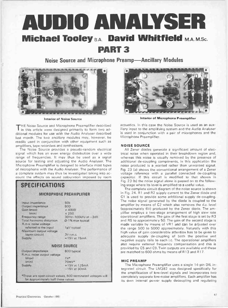
AUDIO ANALYSERMichael Tooley B.A. David Whitfield M.A. M.Sc.
PART 3Noise Source and Microphone Preamp-Ancillary Modules
Interior of Noise Source
THE Noise Source and Microphone Preamplifier describedin this article were designed primarily to form two ad-
ditional modules for use with the Audio Analyser describedlast month. The two ancillary modules may, however, bereadily used in conjunction with other equipment such asamplifiers, tape recorders and synthesisers.
The Noise Source provides a pseudo -random electricalsignal which has an even energy distribution over a widerange of frequencies. It may thus be used as a signalsource for testing and adjusting the Audio Analyser. TheMicrophone Preamplifier is designed to interface most typesof microphone with the Audio Analyser. The performance ofa complete system may thus be investigated taking into ac-count the effects on sound colouration imposed by room
SPECIFICATIONS
MICROPHONE PREAMPLIFIER
Input impedanceOutput impedanceGain (max)
(min)Frequency rangeTotal harmonic distortionR.m.s. noise voltage
referred to the inputMaximum output voltage
(open circuit) 3V r.m.s.Supply -4- 15V at 15mA
50k600x 4000x 25030Hz-100kHz at -3dB0.1% max typical
1µV typical
NOISE SOURCEOutput impedanceR.m.s. noise output voltage
(max)(min)
Supply
600 typical
1V.70mV"415V at 125mA---15V at 30mA
"These are open -circuit values, 600 terminated voltages willhe approximately half these values.
Interior of Microphone Preamplifier
acoustics. In this case the Noise Source is used as an aux-iliary input to the amplifying system and the Audio Analyseris used in conjunction with a pair of microphones and theMicrophone Preamplifier.
NOISE SOURCEAll Zener diodes generate a significant amount of elec-
trical noise when operated in their breakdown region and,whereas this noise is usually removed by the presence ofadditional de -coupling components, in this application thenoise produced is a ,wanted rather than unwanted signal.Fig. 23 (a) shows the conventional arrangement of a Zenervoltage reference with a parallel connected de -couplingcapacitor. If this circuit is modified to that shown inFig. 23 (b) the noise signal alone is passed on to the follow-ing stage where its level is amplified to a useful value.
The complete circuit diagram of the noise source is shownin Fig. 24. R1 and R2 supply current to the Zener diode andC1 is used to provide some additional supply de -coupling.The noise signal generated by the diode is coupled to theamplifier by means of C2 which also removes the d.c. level(approximately 6V) prcduced by the Zener diode. The am-plifier employs a two -stage arrangement of high slew rateoperational amplifiers. The gain of the first stage is set by R3and R5 to approximate y 50. The gain of the second stage ismade variable by means of VR1 and can be adjusted overthe range 500 to 5000 approximately. Naturally with thishigh value of gain considerable attention has to be given toadequate supply de -coupling of both the positive andnegative supply rails to each i.c. The operational amplifiersalso require external frequency compensation and this isprovided by C5 and C9. Twin outputs are available and theseare matched to 600 ohms by means of R13 and R17.
MIC PREAMPThe Microphone Preamplifier uses a single 14 -pin DIL in-
tegrated circuit. The LM382 was designed specifically forthe amplification of low-level signals and incorporates twocompletely separate low -noise amplifiers. Each amplifier hasits own internal power supply decoupling and regulating
Practical Electronics October 198167
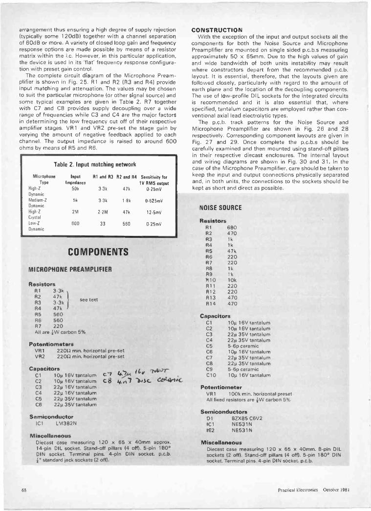
arrangement thus ensuring a high degree of supply rejection(typically some 120dB) together with a channel separationof 60dB or more. A variety of closed loop gain and frequencyresponse options are made possible by means of a resistormatrix within the i.c. However, in this particular application,the device is used in its 'flat' frequency response configura-tion with preset gain control.
The complete circuit diagram of the Microphone Pream-plifier is shown in Fig. 25. R1 and R2 (R3 and R4) provideinput matching and attenuation. The values may be chosento suit the particular microphone (or other signal source) andsome typical examples are given in Table 2. R7 togetherwith C7 and C8 provides supply decoupling over a widerange of frequencies while C3 and C4 are the major factorsin determining the low frequency cut off of their respectiveamplifier stages. VR1 and VR2 pre-set the stage gain byvarying the amount of negative feedback applied to eachchannel. The output impedance is raised to around 600ohms by means of R5 and R6.
Table 2. Input matching network
MicrophoneType
InputImpedance
Al and 133 R2 and 134 Sensitivity forIV RMS output
High -Z
Dynamic
50k 3.3k 47k 0 25mV
Medium -Z
Dynamic5k 3.3k 1 8k 0.625mV
High -Z
Crystal2M 2.2M 47k 12.5mV
Low -Z
Dynamic600 33 560 0.25mV
MICROPHONE PREAMPLIFIER
ResistorsR1 3 3kR2 47kR3 3 3kR4 47kR5 560R6 560R7 220All are kW carbon 5%
PotentiometersVR1VR2
see text
2200 min. horizontal pre-set2200 min. horizontal pre-set
CapacitorsCl l Op 16V tantalumC2 10p 1 6V tantalumC3 22p 1 6V tantalumC4 22µ 16V tantalumC5 22µ 35V tantalumC6 22p 35V tantalum
SemiconductorIC1 LM382N
Cl 4)4, 14,, -1'.4A)r-
c 4.C7 ))is c_ C444-lic
MiscellaneousDiecast case measuring 120 x 65 x 40mm approx.14 -pin DIL socket. Stand-off pillars (4 off). 5 -pin 180°DIN socket. Terminal pins. 4 -pin DIN socket. p.c.b..1" standard jack sockets (2 off.
CONSTRUCTIONWith the exception of the input and output sockets all the
components for both the Noise Source and MicrophonePreamplifier are mounted on single sided p.c.b.s measuringapproximately 50 x 65mm. Due to the high values of gainand wide bandwidth of both units instability may resultwhere constructors depart from the recommended p.c.b.layout. It is essential, therefore, that the layouts given arefollowed closely, particularly with regard to the amount ofearth plane and the location of the decoupling components.The use of low -profile DIL sockets for the integrated circuitsis recommended and it is also essential that, wherespecified, tantalum capacitors are employed rather than con-ventional axial lead electrolytic types.
The p.c.b. track patterns for the Noise Source andMicrophone Preamplifier are shown in Fig. 26 and 28respectively. Corresponding component layouts are given inFig. 27 and 29. Once complete the p.c.b.s should becarefully examined and then mounted using stand-off pillarsin their respective diecast enclosures. The internal layoutand wiring diagrams are shown in Fig. 30 and 31. In thecase of the Microphone Preamplifier, care should be taken tokeep the input and output connections physically separatedand, in both units, the connections to the sockets should bekept as short and direct as possible.
NOISE SOURCE
ResistorsR1 680R2 470R3 1kR4 1kR5 47kR6 220R7 220R8 1kR9 1k1910 10kR11 220R12 220R13 470R14 470
CapacitorsCIC2C3C4C5C6C7C8C9C10
10µ 16V tantalum10p 16V tantalum224 35V tantalum221.135V tantalum5.6p ceramic10p 16V tantalum22p 35V tantalum22µ 35V tantalum5.6p ceramic10p 16V tantalum
PotentiometerVR1 100k min. horizontal presetAll fixed resistors are +W carbon 5%
SemiconductorsDl BZX85 C6V21C1 NE531N1E2 NE531N
MiscellaneousDiecast case measuring 120 x 65 x 40mm. 8 -pin DILsockets (2 off). Stand-off pillars (4 off). 5 -pin 180° DINsocket. Terminal pins. 4 -pin DIN socket. p.c.b.
68 Practical Electronics October 1981
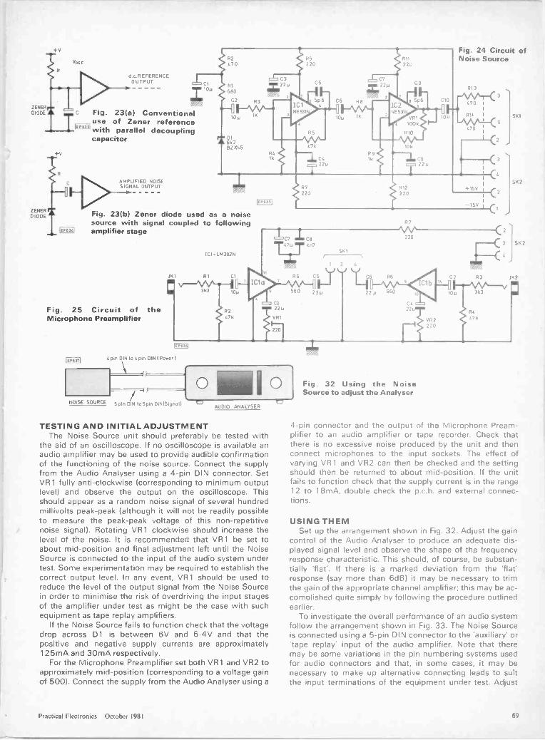
+v
ZENERDIODE
R2VREF 470
ZENERDIODE
V
d c REFERENCEOUTPUT
Fig. 23(a) Conventionaluse of Zener referencewith parallel decouplingcapacitor
C AMPLIFIED NOISESIGNAL OUTPUT
C3C1 3 R1 22u
68010m
C2 R3
FNAC-.19m 16
DI6V2132065
7
IdiNE531
220
CS
5p6
R5
1\KV-'7k
10u
R8
lk
R11
220
R904 1k C822 0 22u
0722u
2
3
IC2NE53I
C9
Fig. 24 Circuit ofNoise Source
R13
-AeAt-r< 3e 5p6 CIO 470
10u jR14Ivvto.<
10k
470
Fig. 23(b) Zener diode used as a noisesource with signal coupled to followingamplifier stage
JK1
Fig. 25 Circuit of theMicrophone Preamplifier
IE P6361
4 pin DIN to 4pin DIN I Power
NOISE SOURCE 5pm DIN to5pm DINlSignuI)
IC1. LM382N
R1 Cl
10m
R2476
IEP63511
C322,
VR1
0
177
220R12
220+15V
-15V
C7 i Cti47M T 4n7
AUDIO ANALYSER
TESTING AND INITIAL ADJUSTMENTThe Noise Source unit should preferably be tested with
the aid of an oscilloscope. If no oscilloscope is available anaudio amplifier may be used to provide audible confirmationof the functioning of the noise source. Connect the supplyfrom the Audio Analyser using a 4 -pin DIN connector. SetVR1 fully anti -clockwise (corresponding to minimum outputlevel) and observe the output on the oscilloscope. Thisshould appear as a random noise signal of several hundredmillivolts peak -peak (although it will not be readily possibleto measure the peak -peak voltage of this non -repetitivenoise signal). Rotating VR1 clockwise should increase thelevel of the noise. It is recommended that VR1 be set toabout mid -position and final adjustment left until the NoiseSource is connected to the input of the audio system undertest. Some experimentation may be required to establish thecorrect output level. In any event, VR1 should be used toreduce the level of the output signal from the Noise Sourcein order to minimise the risk of overdriving the input stagesof the amplifier under test as might be the case with suchequipment as tape replay amplifiers.
If the Noise Source fails to function check that the voltagedrop across D1 is between 6V and 6.4V and that thepositive and negative supply currents are approximately125mA and 30mA respectively.
For the Microphone Preamplifier set both VR 1 and VR2 toapproximately mid -position (corresponding to a voltage gainof 500). Connect the supply from the Audio Analyser using a
560
SKI
5
22,
R6
22m 560
R7
220
C422u
VR 2
220
,411.4.
Fig. 32 Using the NoiseSource to adjust the Analyser
3k3
RC
47k
C1
SK1
SK2
SK2
262
4 -pin connector and the output of the Microphone Pream-plifier to an audio amplifier or tape recorder. Check thatthere is no excessive noise produced by the unit and thenconnect microphones to the input sockets. The effect ofvarying VR 1 and VR2 can then be checked and the settingshould then be returned to about mid -position. If the unitfails to function check :hat the supply current is in the range12 to 18mA, double check the p.c.b. and external connec-tions.
USING THEMSet up the arrangement shown in Fig. 32. Adjust the gain
cont-ol of the Audio Analyser to produce an adequate dis-played signal level and observe the shape of the frequencyresponse characteristic. This should, of course, be substan-tially 'flat'. If there is a marked deviation from the 'flat'response (say more than 6dB) it may be necessary to trimthe gain of the appropriate channel amplifier; this may be ac-complished quite simply by following the procedure outlinedearlier.
To investigate the overall performance of an audio systemfollow the arrangement shown in Fig. 33. The Noise Sourceis connected using a 5 -pin DIN connector to the 'auxiliary' or'tape replay' input of the audio amplifier. Note that theremay be some variations in the pin numbering systems usedfor audio connectors and that, in some cases, it may benecessary to make up alternative connecting leads to suitthe input terminations of the equipment under test. Adjust
Practical Electronics October 1981 69
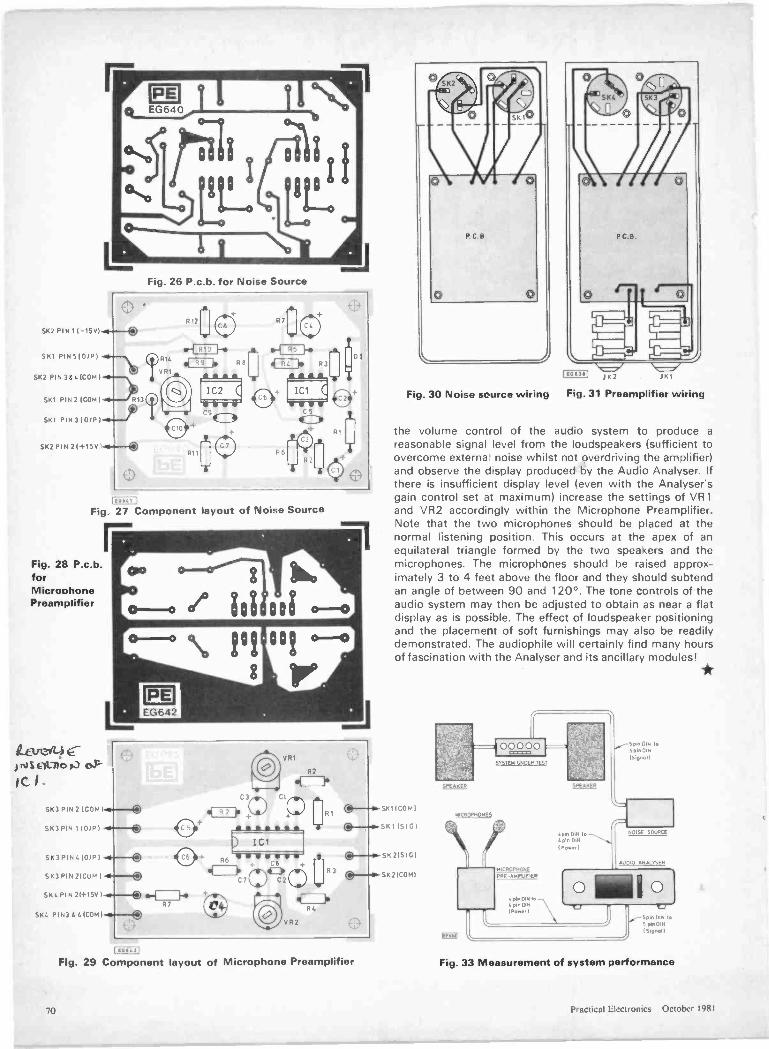
Fig. 26 P.c.b. for Noise Source
SK2 PIN I 1-15V1.---®
SKI PIN 510/P1 -0.- R14
SK2 PIN 3$41COM I -0---\\
SKI PIN 2 ICON I -41-.---)713(1)(0
SKI PIN 310/p1.4-.-fSK2 21-1-15v1-4---®
1C2 (11 W W
R,Ocj
RS bo
R
DI3
IC1
C5
4C:04,Ri
R21:16
LEARN, I
Fig. 27 Component layout of Noise Source
Fig. 28 P.c.b.forMicrophonePreamplifier
Lami4E-) Elt.110 F.3 0P
IC
SK3 PIN 2 ICON)
SK3 PIN 110/P I
SK3PIN 10/171
SK3PIN21CuM
SKi. PIN 21+1581
PIN3 <MOM
881
R2
d=lb
0+ R6 + CB
C)4=),C7 C20 OR34=1
R4
VR2
104 1-0R7
0
Fig. 29 Component layout of Microphone Preamplifier
L
K 0
P.C.B PC B
\=7/1E06311 JK2
\=7"
Fig. 30 Noise source wiring Fig. 31 Preamplifier wiring
the volume control of the audio system to produce areasonable signal level from the loudspeakers (sufficient toovercome externa' noise whilst not overdriving the amplifier)and observe the display produced by the Audio Analyser. Ifthere is insufficient display level (even with the Analysersgain control set at maximum) increase the settings of VR1and VR2 accordingly within the Microphone Preamplifier.Note that the two microphones should be placed at thenormal listening position. This occurs at the apex of anequilateral triangle formed by the two speakers and themicrophones. The microphones should be raised approx-imately 3 to 4 feet above the floor and they should subtendan angle of between 90 and 120°. The tone controls of theaudio system may then be adjusted to obtain as near a flatdisplay as is possible. The effect of loudspeaker positioningand the placement of soft furnishings may also be readilydemonstrated. The audiophile will certainly find many hoursof fascination with the Analyser and its ancillary modules!
SKIICOM)
SKI (SIG)
SK 21S IC)
SK21C0141
SYSTEM UNDER TEST
SPEAKER Melett
MICROPHONES
MICROPHONE
PRE -AMPttFIER
"..'oe.°1]1N"'ortett
I. pm DIN tolion DINI Powor I
Soon DIN toSpin DIN
ISepnall
NOISE SOURCE
Fig. 33 Measurement of system performance
70 Practical Electronics October 1981

TIBIAS - REVERSTREMOLO -- 3
PRESETS - CONr
5,
CC'
JACKHAFN:RUA. I'
''RENO
UlEDI(
IANC
he WERSI ConcepB
PI;Build your own electron c organ with the WERSI system
WERSI presents their new generation of electronic organs andaccessories to you, the do-it-yourselfer. All the tools you need are
ilustrated left, The electronics involved is very revolutionary,mating it very easy to understand. Every non -specialist who canread is able to do it. Building a WERSI organ from a kit can save
you more than half the cost of a similarly equipped ready-made instrument and that means with WERSI and your own
initiative and involvement you can afford a sophisticatedelectonic organ.
Do you have to be a virtuoso or amusic lover to benefit from building a
WERSI organ? No . . . this would meanfailure to recognize the sense of the
hobby. Even after your project iscompleted you will be able to discover
new excitement from the world ofmusic.
Whether you play haunting blues,stomping disco, liturgical hymns ar
classic renditions the new generationof WERSI organs will make yo.ir
life more enjoyable.
TTACKCLARINET --
OBOE - PROGR,ITURGICAL VOICINGASS PATTERNS - SLRIMES HONKYTONKATTERNS - CONTRA CL
TRUMPET - PERCUSSIONECORD PLAYBACK JACK -ASS TUBA -- HARMONICONTRABASS - FREE RUN WA,RCHESTPA - BELLS - FRE'V
'T,HIA
WALI
EltTR
NA
E
U
A
U
IA
T
CL
fAURA SOUNDS LTDare :he first company tosuccessfully market WERSIorgans and kits in the U.K.We have three modern show-rooms where we pride ourselvesyou will receive a friendly welcomeWhy not pop in and see the WERSIrange for yourself - we can alwaysarrange a free demonstration. Wealso offer a free technical telephonesupport service which is second to none.
Alternatively, fill in the coupon belowfor the full colour catalogue. Forimmediate action telephone DI -668 973324 haur answering service quoting Access/Barclaycard Number.
*- 1
CC'- BASS GUITAR - MEC
UN.0 - MEDIUM SUSTAIIOMPUTERS - PIANO - CC
AURA SOUNDS urn. F CK - PRI,14-15 Royal Oak Centre, Brighton Road, Pirley, REPISurrey.
OE - ITel: )1-668 973317 Upper Charter Arcade, Barnsley, Yorksiiire., /CAL VTel: :0226) 5248 TT1729 Coventry Road, Sheldon Wrmingham. Tel: ES021-707 8244
A ilftdAr EIA' PATNOW OPEN - The MicroCentre, Abany Road, 0 - TRNewquay, Cornwall. Tel: Newquey 5953
COWERSI an
r
...ova"'
Want to know more? Justfill in the coupon below,
enclosing £1.00, and we'llsend you the big, full
colour catalogue. It willanswer all your questions.
AT PERC:ISSIROGRAMMABNG CELES
- SOL
0
NS
S -
N --
L -N -
PERCUSSION - SOUNt,K JACK - LONGSUSTAN'ONIC DRAWBARS -- ON.
'4 WAH - DIAPA SON --1\ICH ACCORDIAN -
MEDIUM SUSTAN' - PIZZICATO -
BAG PIPES -- TIBIAS
N -BL A
-f,5' T
MEM.VISA
Please send me the full colour WERSI Catalogue.I enclose cheque/P.O. for £1.
NAME
ADDRESS
Send to Aura Sounds Ltd., 14/15 Royal OakCentre, Brighton Road, Purley, Surrey.
LURA - The Winning Combination
PE I0_
Access /Barclaycard 24 hr telephone serviceFREE 'IMES -

EXCITING OFFERS!DIGITAL VOLTMETER MODULE
Fully built & testedPositive and negative voltages with an ISO
of 999mV which is easily extended.Requires only single supply 7 - 12V.High overall accuracy ± 0.1% 1 digit.Large bright 0.43" (11 min) LED displays.*Supplied with full data and applications
information.
Using this fully built and calibrated module as a basis now means that you caneasily build a wide range of accurate equipment such as multimeters, thermometers,battery indicators, etc. etc. at a fraction of the cost of ready-made equipment. Fulldetails are supplied with each module showing how to easily extend the voltage rangeand measure current, resistance and temperature. Fully guaranteed, the unit has beensupplied to electricity authorities, Government departments, universities, the P.O.and many companies.
Temperature Measurement £2.15 .VATAll easily constructed kit using an I.C. probe providing a linear output of 10mVi°Cover the temperature range from -10°C to *100°C. The unit is ideal for use inconjunction with the above DVM module providing an accurate digital thermometersuitable for a wide range of applications.
Power Supply £4.95 +VATThis fully built mains power supply Provides two stabilised isolated outputs of 9Vproviding current levels of up to 250mA each. The unit is ideally suited for powering the DVM and the Temperature Measurement module.
ULTRASONICALARMMODULEFully built& tested
Range adjustablefrom 5' - 25'
A reallyeffective fully built
module which containsboth ultrasonic transmitter
and receiver, together with thenecessary circuitry for providing the
appropriate delays and false alarm supp-ression. Using this module with a suitable
12V power supply and relay unit such as thatshown, a really effective though inexpensive intruder
alarm may be constructed. The module, which is supp-lied with a comprehensive data sheet, is easily mounted in
a wde range of enclosures. A ready drilled case, together withall the necessary hardware, is available below.
Power Supply & Relay Unit£3.95 +VAT
Incorporating a stabilised 12V supply and as.p.c.o. relay with 3A contacts, this unitis designed to operate in conjunction withthe above ultrasonic unit. Filly built andtested, its compact size makes it ideal forconstructing the smallest of un ts.
Hardware Kit £3.95rVATA suitable ready drilled case together withthe various mounting pillars, nuts and bolts,and including a mains switch and 2mmsockets designed to house the ultrasonicalarm module, together with its associatedpower supply. This hardware kit provides anideal solution for assembling the economicalalarm system. Size 153mm x 120mm x 45mm
In addition to the above a wide range of competitively priced electroniccomponents is stocked. Please telephone your specific requirements. AILV.A.T. must be added on all items. Shop hours 9 - 5.30 (Weds. 9 - 1)
ex -stock delivery on all items. Units on demonstration, callers welcome.Post and packing charge 50p per order. S.A.E. with all enquiries please.
RISCOMP LiMiTEDDept: PE 1,21 Duke Street,Princes Risborough, Bucks.Tel Princes Risborough (084 44) 6326
MICRO TIMES I VOUCH50p 0 F F
ER II When E5 plus order of CMOS.'
Telephone Bideford (023 72) 79798 771 or LINEAR is placed
19 Mill St., Bideford, North Devon EX39 2J R, England
INTRODUCINGCMOS
CMOS ANDTHYRISTORS
M. see below for nprices
74LS175 59p4001 12p C106D 289 7415221 83p4002 12p 7415244 83p4006 68p 741_5245 £1.204007 130 VOLTAGE
REGULATORS7415251 45p
4008 60p4010 36p
741_5257 55p74LS261 £3.10to
4011 120 7805 5V 53p 7415366 38p4012 180 7812 12V 53P 7415373 78p4013 33;; 7905 5V 55P 741S374 78p4014 7912 12V 58P 7415393 60p4015 2p6 100mA4016 78p 78105 5V 29p
LOW PROFILE4017 53p 78L12 12V 29p4018 58p 500mA OIL SOCKETS4019 36p 79M12 12V 62p4020 65p 79M05 5V 62p 40 pin
28 pin 309p4023 18P4024 38p
723 32p 24 pin 24p
4025 148 22 pin 2204026 £1.28 MIWOlp..... 18 pin 18p4027 16 pm 14p4028 8204029 70p
74LSO1,Z-741502 13p
4 pin1
8 pin 19p4030 48p 74LS03 13p4031 £1.954040
741SO414P.,., Ill's88p
4042 55p4044 60p4046 74p
741508 '''P741S10 139741514 5°P,.,741520 -P
TIL32 45pTI L209 red 10p111232 green 18p
4047 78p 741526 4p TIL212 yellow 16p4048 44p4049 27p4050 27p4051 6004052 80p4056 £1.50
741530 4,1,,. A.,7741532 .-Z741538 "741.542 39p
74LS47 410741573 21p
7I1_216 red 180TIL228 red 20p711220 red 12pTIL224T11311 £61.15%711312/3 £1.00111321/A [1.164060 86p
4063 £1.18741574 l'". P741575 29p TIL330A f1.15
4066 369 741586 36p4068 1894069 15p
741590 35p741593 38p LINEAR IC's
4070 22p 741_5107 40p NE555 17p4071 18p 74LS112 70p NE556 48p4075 20p 7415123 450 RC4136 65p4077 22p 7415125 29p LM301AN 26p4078 20p 7415132 50p LM311P 45p4081 18p 7415138 39p LM318 Cl 454093 42p 74LS151 75p LM324N 42p4503 659 7415155 489 LM339N 40p4510 86p 7415157 35p LM348N 75p4511 51p 7415161 42p LM358P 38p4518 70p 74LS163 42p LM380 65p4520 70p 7415164 50p 11143900N 46p4560 02.20 7415173 759 LM3914 £2.004572 30p 7415174 77p LM3915 £2.00
Return Voucher with order. IPEOlemmsimmsio
LM 13600SN76477NUA709LM741UA733UA747UA74871074CN71081CP71082CP
C1.20£1.76
28p169
5Sp£122
3Sp60p
TL084CN1M3302T149014881489872687288795ICM7555
98p85p
E1.1070p
E17.2g£1.50£1.50
80p
NEW S-100PROM BLASTER
FAMILIES OF EPROMSIAccepts 1K/2K/4K or BKEpromsExtended Device OptionPhantom Slave Option.All Programming Character-istics. Software Controlled,Accepts Single or 3 SupplypartsDevice Address SwitchSelectable
On Board Wait States.Put your frequently used rout-ines into EPROM,BAREBOARD £49PROMWRITER £40KIT £176Inc' all parts sckts.. and Prom -writer.Del, 2 weeks.
FLOPPY DISCCONTROLLERS
101791-2WD1691DWD2143-01
£19.50f32.00f14.50£6.00
SPECIALincludes F01191 2 WI:11691D
Pkg. £60.
WD2143-01Set data available f3.00151p SAE please/
6809 SINGLE EOARD COMPUTERUses Motorolaspowertil MC6809 CPU4K/8K/16K ROM 2F RAM ACIA. PIA. 8080simulated I/O. RS -222 Handshake 8 sal BaudRates.BARE BOARD f411.Uses 6809 6850 6821 - Buy set for f18.40COMPLETE KIT f175 plus 15% VAT . El P&PManual includes: 11.17in. Schematic Pans LimUser notes. Software listings and more'ADMONS 127161 £24.00
DATA AVAILABLE ON 6809SAE please.
MEMORIES
25.2114 450ns £1.30 £1.262114 300ns £1.45 [1.407C5514P - £3.65 £3.4514K CMOS RAM I1K s 41450ns4116 200ns £1.20 £1.164116 150ns £1.70 £1.65CMOS RAM
5101 f3.45 £3.40HM6116-3116K 150nsr15.50 £16.26
EPROMS 1 25.2708 450ns [2.55 £2.502716 5v 45Ons £2.65 £2.602732 Intel type f9.90.Buy 4 off for £49.00
CPU's65026504680268098080A8085AZ80Z.80A
£5.45£7.26£5.70
£16.00£4.16£6.46£4.00£5.85
652065226532681068216845685068528212821682288255Z80 CICZ80 PIO280ACTCZEIOAPIO280 DMAZ8OADMAZ80 S10/0ZEIOAS10/0
E3.10E5.55E7.70£2.50E1.90
£15.00£1.90C3.25£1.75f1.75£3.96£4.10£4.25£4.215£5.40[5.40
£14.95£18.00f17.60£22.50
EPROM ERASERFast Erase timeEpoxy coated steel caseHolds up to six EPROMSSafety interlocked U.V. sourceData available. £48.50 se.
AN, -3-8910GI SOUND COMPUTER CHIP
Feature.:- Full software control of sound generation- Interfaces with most 8 -bit and 16 -bit microprOCMSOnl
3 independently programmes analog outputs- Two 8 -bit general purpose I/O pods- Single .5 volt supply.
SPECIAL PRICE f6.915Date £1. Large SAE please.
VEROBLOC SOLDERLESSBREADBOARD
360 reliable contacts.Will accommodate any size IC.Can be full interlocked one with another. £3.66 eachS100 Prototyping BoardsMicroboard pattern 06-2175L e16.40Sp Pad Universal Pattern f16.40Prototyping Board for your APPLEATT 2020 65.37
ANTEX SOLDERING IRONSModel CX. 17W [4.29Kit SKI 15W 111.00incl. base/stand solderKit SK3. 17W te.00Kit SK4. 25W IL11.00SK3 and SK4 complete with stand.MLX Repair Kir [4.1110can be used where no mains elec. is available.Spare Bits. 50p
ORDERING INFORMATIONPlease add 50p P&P.Plus 15% VAT to all orders.EXPORT ORDERS ACCEPTED.Add 15% P&P on total order.VAT not applicable.ACCESS/BARCLAYCARD WELCOMEPlease add 15% VAT after P&PSchools, Univ. Official Orders welcome.
Z80 S10/1 C17.50 Z80 510 2 £17.60280A510/1 £22.50 2130AS10. 2 £22.50
Prices subject to change without notice
72 Practical Electronics October 1981

OVERLOAD PROTECTION
Rudolph Goebel of West Germany haspatented (BP 1 586 495) an overloadprotection circuit for loudspeakers. Thepatent, which dates back to 1976, is aimedat safeguarding a speaker driver againstdamage or destruction by signal overload.Although protection circuits are well knownthe inventor claims that his design has amore precise point of response.
By way of reference a circuit previouslypatented in BP 1 407 824 is shown inFigure 1. When the breakdown voltage ofzener diode ZD is reached, it becomes con -
Copies of Patents can be obtained from:the Patent Office Sales, St. Mary Cray. Orpir.gton, Kent. Price f 1.45 each.
ductive to charge capacitor C via resistorR1. Relay S then pulls in and the audiosignal is fed to the loudspeaker via resistorR2 which prevents overload.
The new circuit is shown in Figure 2. Theaudio signal is rectified by diode D1 andwhen relay S is at rest capacitor C1 chargesvia resistor R1. Zener ZD conducts whenthe DC across divider R4, R3 reaches itsbreakdown voltage. R4 is then shunted and
Fig. 1
relay S pulled in. Capacitor C1 now con-nects to the base of switching transistor TRto hold it in conductive state for a durationdepending on the time constant of C1, R3.The loudspeaker is meanwhile connected tothe audio signal by way of resistor R2. Therelay returns to its normal state when thesignal drops and the Zener and transistorbecome non-conductive after C1 has dis-charged.
Fig. 2
EiA SpecialOffer!
ispownstroR
Including VAT,ostage and packing.
==To tie up with our Digital Design series we have arranged this
special offer with G.S.C. The kit contains one ExperimentorSolderless Breadboard, an Experimentor Scratchpad for layoutdesign and two Matchboard drilled p.c.b.s. for final constriction.
To: G.S.C. (U.K.) Ltd., Shire Hill Industrial Estate,Saffron Walden, Essex CB11 3AQ. Tel. (0799) 21682
Is' Please send me ... Experimentor Kits at £9.25 each.
11E I enclose P.O./Cheque No. Value
1
lu< Make cheques payable to G.S.C. Ltd. IY
1°o IName
Ili 1c Address
IIIoI. i
01 a i a..i.., i
a Please allow 28 days for delivery
1'' OFFER CLOSES FRIDAY 30th OCTOBER 1981 IcoI.I
-z NameI
I2.' II Address IIE I
0
au IIco
I : From: G.S.C. (U.K.) Ltd., Shire Hill Industrial Estate,'
meowimumsmigmmo umSaffron Wa den, Essex CB 3AQ.LTel. (0799) 21682 I
Practical Electronics October 19ii1 73
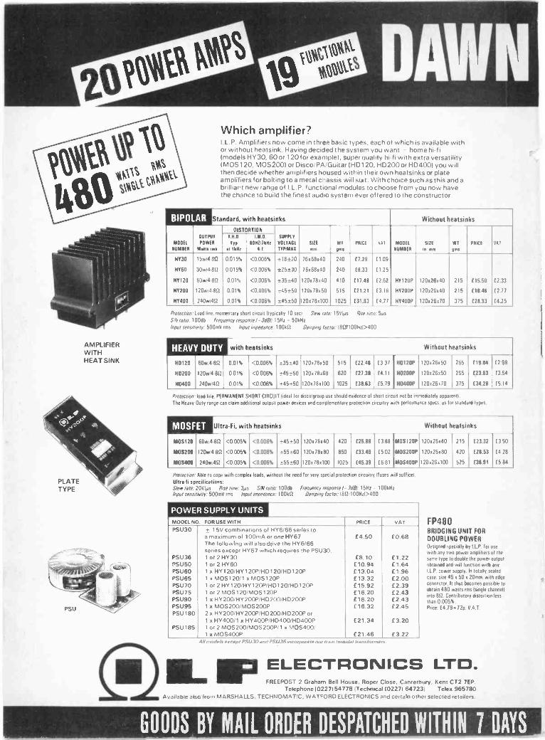
AMPLIFIERWITHHEAT SINK
0,,ELECTRONICS LTD.FREEPOST 2 Graham Bell House, Roper Close, Canterbury. Kent CT2 7EP.
Telephone 10227154778 (Technical 102271 64723) Telex 965780A, 11 th,.. .1,,, from MARSHALLS, TECHNOMATIC, WATFORD ELECTRONICS and certain other selected retailers.
MOOE1
NUMBER
HY30
14060
HY120
HY 200
HY400
Which amplifier?I.L.P. Amplifiers now come in three basic types, each of which is available withor without heatsink. Having decided the system you want - home hi-fi(models HY30, 60 or 120 for example), super quality hi-fi with extra versatilityIMOS120, MOS2001 or Disco/PA/Guitar IHD120, HD200or HD4001 you willthen decide whether amplifiers housed within their own heatsinks or plateamplifiers for bolting to a metal chassis will suit. With choice such as this and abrilliant new range of I.L.P. functional modules to choose from you now havethe chance to build the finest audio system ever offered to the constructor.
Standard, with heatsinks
DISTORTIONOUTPUT
POWER
Watts nu
15w4812
30w:4 812
60w:4 812
120w 4 80
240w 40
Typ
at 111111
0.015%
0.015%
0.01%
0.01%
0.01%
I.M.O.
11011217411.
4:1
<0.006%
<0.006%
<0.006%
<0.006%
<0.006%
SUPPLY
VOLTAGE
TYPIMAX
± 18±20
±25±30
±35±40
± 45±50
±45±50
Without heatsinks
SIZE
awWT
MnPRICE VAT MODEL
NUMBER
SIZE
in matWT
gms
PRICE VAT
76x613140 240 £7.29 t1.09
76x68x40 240 £8.33 t1.25
120x78x40 410 £17.48 (2.62 HY120P 120x26x40 215 £15.50 (2.33
1200650 515 £21.21 (3.18 HY200P 120 ii26s40 215 E 18.48 (2.77
120081100 1025 £31.83 (4.77 HY400P 120x26x20 375 £28.33 £4.25
Protection. load line. momentary short circuit Ityp cally 10 se I Slew rate 15V 4is Rise time 50sS/N ratio 100dh Frequency response- MI 5Hz - 50 HzInput sensitivity: 500mV rms Input impedance 100k4 Damping lac or 1812 100Hri>400
HEAVY DUTY with heatsinks Without heatsinks
110120 60w4 8f2 0.01% <0.006% ±35±40 1200800 515 (22.48 (3.37 HD120P 120126'50 265 £19.84 (2.98
110200 120w14.812 0.01% <0.006% ±45±50 120 x 78 x 60 620 £27.38 (4.11 H0200P 120126x50 265 £23.83 £3.54
140400 240w411 0.01% <0.006% ±45±50 120081100 1025 £38.83 (5.79 110400P 120126170 375 £34.28 f5.14
Protection load line. PERMANENT SHORT CIRCUIT Ideal for discogroup use should evidence of hart circuit not he immediately appar nt).
The Heavy Only range can claim additional output power devices and complementary protection circuitry with performance specs as for standard types.
MOSFET Ultra-Fi, with heatsinks Without heatsinks
MOS120 60w4 812 <0.005% <0.006% ±45±50 120x 78x40 420 £25.88 (3.88 PAOS120P 120x26x40 215 £23.32 0.50
MOS200 120w:4 80 <0.005% <0.006% ±55±60 120x78.80 850 (33.48 £5.02 MOS200P 120,126180 420 £28.53 (4.28
MOS400 240w14f2 <0.005% <0.006% ±55±60 120178x100 1025 £45.39 £6.61 MOS400P 120126.100 525 (38.91 (5.84
Protection Able to cope with contrite loads, without the need for very specie protection circuilr doses will suffice)
Uhrefi specifications:Slew rate. 201/,').is Rise time. 30s SIN ratiO 100dh frequency response - 3dBI: 15Hz 100kHzInput sensitivity 500mV rms Input impedance 100kf2 Damping factor: alf2:100H11>400
POWER SUPPLY UNITSMODEL NO. FOR USE WITH PRICE VAT
PSU30 + 1 5V combinations of HY6/66 series toa maximum of 100mA or one HY67 £4.50 £0.68The following will also drive the HY6/66series except HY67 which requires the PSU30.
PSU36 1 or 2 HY30 E8.10 C 1.22PSU50 1 or 2 HY60 £10.94 £1.64PSU60 1 x HY 120/11Y120P/HD 120/HD 1 20P £13.04 £1.96PSU65 1 x M05120/1 x MOS120P E 13.32 E2.00PSU70 1 or 2 HY 1 20/HY 120P/HD 120/14C1120P £15.92 £2.39PSU75 1 or 2 MOS 120/MOS 120P E16.20 £2.43PSU90 1 x HV200/HY200P/HD200/HD200P E16.20 £2.43PSU95 1 x MOS200/MOS200P £16.32 £2.45PSU180 2 x HY200/HY 200P/HD200/HD 200P or
1 x HY400/ 1 x HY400P/HD400/HD400P £21.34 £3.20PSU185 1 or 2 MOS200/MOS200P/1 x MOS400/
1 x MOS400P £21.46 E3.22
FP480BRIDGING UNIT FORDOUBLING POWERDesigned specially by I P for use
with any two power amplifiers of thesame type to double the power outputobtained and will function with anyI.L.P.power supply In totally sealedcase, site 45 x 50 20mm, with edgeconnector. It thus becomes possible toobtain 480 watts rms (single [barmeninto 812. Contributory distortion lessthan 0.005%.Price: £4.79.72p. Y.A.T.
Ad models except PSU30 and PSU36 incorporate our own torn dal transformers
GOODS BY MAIL ORDER DESPATCHED WITHIN 7 DAYS

OUT NOW!AMBIT'S NEW CATALOGUE
In an attempt to collate and organize our burgeoning rangesof 'stock' components In3iv over 7000 line items), we haveat last produced a 'concise' 80 page parts catalogue tosupplement the popular 'Tecknowledgey' series of 'wordy'applications catalogues, which now lists a wide range of basiccomponents - as well as oar unique RF and Communicationscomponents. The World of Radio and Electronics containseverything the informed electronics user needs, at priceswhich we guarantee will match the lowest on the market forequivalent product.Prices appear on the page alongside the part numbers, andthe catalogue is now updated quarterly - available eitherdirect from here ,; 60p all inc) or at most newsagents andbookstalls where you can find electronics publications. Soas well as all the 'run -of -mill' items like resistor, capacitors,hardware, solder etc - you now have the first genuinely,ornnlete parts source for the radio, communication, elec-tronics, computer user.
Ambit International200, North Service Road,
Brentwood,Essex CM14 4SG
INDEX TO ADVERTISERSAcorn 4, 34, 39Adam Hall Supplies 81Ambit 87Apollo Elektronics 80Audio ElectronicsAudio Video Services
76. 4710
Aura SoundsBarrie Electronics
7178
Bi-PakBolster Instruments
1381
Breadboard .81 ExhibitionBritish National Radio & Electronics School
6511
Cambridge Kits 81Cambridge LearningChromasonic Electronics
79
Clef Products 86Crofton Electronics 10CR Supply Co.C.U.A.
8078
Davian 76ElectrovalueElectroware IOK Machine & Tool)
865
GeminiGJD Electronics
8781
Global Specialties CorporationHameg Limited
534
HeathkitHenry's Radio 12.
8379, 84
Hiykon Ltd. 81ICS Intertext 4, 80ILP ElectronicsIndustrial Supplies
74. 75.8581
Maplin Electronics Cover 4Micro Times 72Midwich ComputersMillhill
8276
Modern Book Co 86Modus Systems 12MusicraftNewbear
8412
ParndonPhonosonics
106 7
Pitman BooksProto Design
8581
Powertran Cover 2Prentice -Hall International 10Radio Component Specialists 86Radio & T.V. Components 16Rapid Electronics 76Riscomp Limited 72Roden Products 81Safgan 8Scientific Wire Co 81Service Trading 77Sheban Electronics 78Sinclair Research 14. 15Swanley 85Tandy Corporation Cover 3Technomatic 88Tempus 56Titan 8T & J Electronic Components 80T.K. Electronics 66T.U.A.C. 84Vero 83Videotone 82Watford Electronics 2.3William Stuart Systems 81Wilmslow Audio 84
INTERESTED IN
ELECTRONICS?TRY A ZEDPACK!
COMPONENTS AT A PRICEEVERYONE CAN AFFORD
21 300 mixed ; and I watt resistors £1 95Z2 150 mixed 1 and 2 watt resistors 50Z3 300 mixed capacitors, most types
£3 95Z4 100 mixed lectrolytics 12 20Z5 100 mixed polystyrene caps £2 20Z6 300 mixed printed circuit
components E1 95Z7 300 sired printed circuit resisters
£1 45Z9 100 mined miniature ceramic and
plate caps £1 20210 25 assorted pots. El 50Z11 25 zssorted presets, skeleton etc. E.1712 20 assorted vdr's and thrmistoes
E1 20213 11b mixed hardware. Nuts bolts
self -tappers, sleeving. et, £1 20Z14 100 mixed, new and marked, full spec.
transistors. Pack includes - BC148.13E154, 13E274, BC212L, BC238, BC184L,PBC108 and, or lots of similar types
E4 95Z15 IN mixed diodes includingi-zener,
powe', bridge, signal, germanium,silicon etc. All full spec. £4 95
Z16 20 1N4148 E1717 20 1N40031002 EtZ18 20 assorted zeners, 1 watt and 400mw
E1 SO219 12 125" TIL 209 RED. LED'S ElZ2010 Assorted switches, includinc push
button, slide, multipole miniature etc.Fantastic value. £1 20.
UHF MODULATORSVideo in UHF out, Calibrated to charnel 36(625 line UHF) housed in metal box 21"2" I" with 9' coaxial lead, TV plug andconnec-ion data. E2 SO ea. 3 for ELAluminium finish slider Snobs, standardfitting. 10 for E121110µA Miniature level/bet. mesas, as
fitted to many cassette recorders. MilrDeluge FIBREGLASS printed circuitetching kits.Includes 150 sq ins. of copperclad F/G board.1 lb ferric chloride, (made for U.S army toMIL. SPEC.), 1 dalo etch resist pen, abrasivecleaner, tweezers etch resist dish and in-structions. OUR PRICE f 5.95llb of FeCI. £2-25.
To: "GEMINI ELECTRONIC
150 sq. ins, single sided board. E2 20150 sq. ins. double sided board. E3-34100 Miniature reed switches. E2-30100 Subminiature Reed Switches. £4 20
SMALL MAGNETSWith hole in 6 for £1
P/B SWITCH BANKSThese cost a fortune! Were made forvarious music centres. Includes indepen-dent and interdependent latching typesmulti pole cio etc. Can be modified.Can't be repeated. 3 Banks for £1,KNOBS for Switch Banks 10 for L1.Chrome or spun aluminium finish.
MINIATURE MAINS TRANSFORMERSTop quality. Split bobbin constructionwill give 4 5V-0-4 5V at 250MA. Ii"" 11"
li", all sorts of uses. ONLY E13 for £2 50.
PP3 Battery Connectors 10 for 50p.Miniature Press to Make Switches, Redknob, 50p.Subminiature S.P.C.O. Slide Switches.
Mfionriasotupra D.P.C.O. Slide Switches.6Standard 2P, 3 Position Slide Switch.4 for 50p.
Fuse Holders including 20mm,P.0 . Panel and chassis types. Pack of 7
401113. CMOS house coded Tube of25 ONLY £2.502012 Static RAM, house coded 450NiS60p each 10 for CS 25 for £10
9 Section, Chrome on Brass TelescopicAerial. Plugs into any 3 5mm socket.Approx 25" extended Et each. 3 for E2 SO.Hi Power Infra Red Transmitter 5mmLED. TIL 30 60p ea. 3 for E1 50.Crystal Clear 3rnm LEDS very prettyRed, Green, Yellow. 10 of one colour £1.10 of each E2 SS.
ALTERNATOR RECTIFIERSMake lovely 60 amp bridges. Ideal forHigh Power Battery Chargers.Type 4AFI. Set of 4 (2 neg. case2 pos. case) E2
Special Purchase enables us tooffer Mallard C201 Polyester Cairo-citors (Liquorice Allsorts) at theunbeatable price of E2 for 100 mixed.EIS for IMO. These consist of factoryclearance lots i.e. spillages, floorsweepings cosmetic rejects etc AlsoMullerd Mini Electrolytic s. 200mixed C2.
COMPONENTS" DEPT PE"THE WAREHOUSE" SPEEDWELL ST. LONDON S.E.8.
Where shown. Send Cheque or Postal Order. Plus 60p P&P. and 15'. VAT.Please Quote ZEC Code. Schools etc. SEND OFFICIAL ORDER
ZED PACKS now evadable for Callers at 50 Deptford Broadway, London, S.E.8.
Practical Electronics October 1981 87

TTL4 byTEXAS
7400 llp7401 12p7402 12p7403 12p7404 14p74SO4 60p7405 18p7406 30p7407 30p7408 16p7409 16p7410 15p7411 20p7412 20p7413 25p7414 35p74C14 90p7416 27p7417 27p7420 17p7421 20p7422 22p7423 25p7425 30p7426 30p7427 30p7428 30p7430 17p74L30 50p7432 30p7433 30p7437 30p7438 30p7440 1774417442A7443744474457446A7447A74487450745174537454746074707472747374747475 30p74L75 150p7476 32p7480 50p7481 100p7482 54P7483A 60p7484 100p7485 100p7486 30p7489 210p7490A 30p7491 60p7492A 40p7493A 30p7494 84p7495A 60p7496 50p7497 180p74100 100p74104 65p74105 65p74107 34p74109 40p74110 55p74111 70p74116 100p74118 100p74119 100p74120 110p74121 28p74122 48p74123 48p74125 55p74126 60p74128 60p74132 50p74136 50p74141 75p74142 200p74145 90p74147 120p74148 100p74150 100p74151A 50p74153 50p74154 90p74156 90p74157 50p74159 120p74160 70p74161 70p74162 70p74163 70p74164 90p74165 90p74166 90p74167 200p74170 200p74172 300p74173 90p74174 75p74175 75p74176 70p74177 90p74178 160p74180 80p74181 160p74182 90p74184A 120p74185 120p74186 500p
7 ;221129SOp
74LS1074 LS11
" ,InTn' 74 LS13
939 74LS1474LS20
70.' 74LS21179 741527tip 741_6301732
772E179 741538
m 7AV326 74LS55249 74LS73
74LS7474L575 28p74LS76 32p74L583 50p74LS85 70p74LS86 25p74LS90 35p74LS93 35p7415107 45p74LS112 100p74LS123 50p74LS124 110p74LS125 30p74LS126 30p74LS132 50p74LS133 30p74LS136 25p74LS138 35p74LS139 35p74LS145 75p74LS151 35p74LS153 35p74LS154 200p74LS155 50p74LS157 34p74LS158 60P74LS160 45p741.5161 45p74LS162 45p74LS163 45p741.5164 90p74LS165 100p74LS166 120p74LS173 70p74LS174 60p74LS175 60p74LS181 200p74LS190 50p74LS191 50p74LS192 50p74LS193 60p74LS194 50p74LS I 95 50p74LS196 60p74LS221 60p74LS240 90p74LS241 90p74LS242 80p74LS243 80p74LS244 80p74LS245 90p74LS251 50p74LS253 40p74LS257 75p74LS259 120p74LS266 100p74LS273 90p74LS283 45p74LS365 50p74LS366 50p74LS367 50p74LS373 80p74LS374 80p74LS375 50p74LS377 90p74LS378 70p74LS390 60p74LS393 60p741.5640 300p74LS641 300p74LS645 300p74L5670 225p
74190 75p74191 75p74192 75p74193 75p74194 90p74195 95p74196 70p74197 80p74198 120p74199 120p74221 90p74C221 150p74251 100p74259 120p74265 90p74278 200p74279 110p74283 100p74284 150p74285 150p74290p 150p74293 150p74294 200p74298 200p74365 50p74366 50p74367 50p74368 50p74390 100p74393 90p74490 150p
74LS SERIES74LS00 12p74LS02 12p74LSO4 14p
15p15p15p15p25p45p15p15p16p15p16p18p16p45p45p20p25p18p
4000 SERIES4000400140024006400740084009401040114012401340144015401640174018401940204021402240234024402540264027402840294030403140334034403540404041404240434044404640474048404940504051405240534054s4055405640594060406340664067406840694070407140724073407540764081408240934094409840994412450245034507451045114514451545164
15p16p15p60p20p60p40p40p14plap35p60p60p30p45p70p45p65p75p70p20p40p20p
130p32p60p75p40p
170p180p200p110p55p70p65p75p70p70p75p55p27p27p60p80p60p
150p125p120p500p90p
100p35p
400p20p20p20p20p20p20p20p60p20p20p40p
175p90p
120p1100p
70p50p45p70p50p
150p150p75p
4520 45P70p4521 150p4528 75p4532 110p4534 500p4536 300p4538 120p4543 100p4553 320p4560 180p4569 180p4583 100p4584 45p40097 90P14433 1100p14500 700p14599 290p
INTERFACEIC.DP8304 450pMC1488 65pMC1489 65p58174 C1275107 160p75182 230p75324 375p74325 375p75361 150p75363 225p75365 150p75451 72p75491/2 96p8T26 140p8T28 140p8795 140p8T97 140p81LS95 120p81L596 140p811597 120p81LS98 140p9601 120p9602 220p
93 SERIES93019302930893108311931293149316932193229334
VEROBOARD160p 0.1175p (copper clad)316p 2 31 75p275p 2 5 85p275p 3 31 85p160p 3 5 95p165p 3 17 380p225p 4 17 420p225p Pkt of 100 pins 50p150p Spot lace curter 85p340p Pin insertion
tool 99pLINEAR I.CAY1-0212 600pAY1-1313 668pAY1-1320 320p AY1-5050 140pAY -3-8910 750pAY3-8912 650pAYS-1224A 240p415-2376 700p
CA3019 80pCA30284 90p
CA3046 70p CA3048 225p043080E 72p
CA3089E 225pCA309040 375pCA3130E 100pCA3140E 50pCA3160E 100pCA3161E 160pCA3162E 490pCA3189E 300pHA1388 260p1017106 850pICL8038 300pICM7555 80pLF351 45pLF356 95pLM3014 27pLM311 70pLM318 200pI.M319 200pLM324 45pL M339 75pLM348 80p
LM377 175p LM380 75p LM381AN 180pLM386 95pLM387 115pLM389 95pLM393 100pLM709 36pLM710 60pLM725 350pLM733 100pLM741 20pLM747 70pLM748 35pLM2917 250pLM3900 60pLM3909 70pLM3911 130pLM3914 210pLM3915 225pLM3916 225pLM4136 70pLM13600 120pMB3712 200p
MC13109 150pMC1458 40pMC1495L 350p
'MC1496 70p MC3340P 120pMC3403 90pMM57160 620pNE531 150p
VERO WIRINGPENPlus spool 340pSpare spool(wire) 80pCombos 7p each
NE555 20pNE566 60pNE564 420pNE565 130pNE566 155pNE567 140p
NE571 425pNE55344 250pPLLO2A 600pRC4136 70p5566B 250p
SAD1024A 1250pSFF96364 800pSN76477 175p747120 120pTA7204 250pTA7205TA7222TA7310
.T84641811TBA65 ITBA800TBA810TBA820TC4940
TC4500A"TDA1004ATDA1008TDA1010
TDA1022TDA1024TDA10340TDA1170TDA2002V
TDA2020TL064TL071/81TL072/82TL07411084T1.170UAA170ULN2003UPC1156HXR2206
ZN414ZN419ZN424EZN425EZN427E -8ZN10346ZN1040E74C92374C92574C928
250p200p200p300p200p90p
100p90p
175p250p3009320p225p600p120p250p300p325p320p150p
45p75p
130p110p
50p175p100p300p300p
90p225p135p350p650p200p700p500p550p600o
VOLTAGEREGULATORS
Fixed PlasticTO -220
14 .Ve Ve
5V 7805 SOp 790512V 7812 50p 791215V 7815 559 791518V 7818 55p 791824V 7824 55p 7924100mA TO -92
5V 78105 309 7910512V 78112 30p 7911215V 78115 309 79115OTHER REGULATORSLM309K 135p TBA625BLM317T 200p TL430LM323K 500p 78H05KCLM723 37p 78MGT2C
55p55p80p60p60p
80p80p80p
120p130p550p140p
TRANSISTORSAC126
BFF180BFR81
25p25p
AC127/8 20p BFX29 30pAC176 25p BFX30 34pAC187/8 25p BFX134/5 30p41116/7 50p BFX86/7 30pAD149 70p BFX88 30pA0161/2 45p BFWIO 90pAU107 250p B FY50 30pBC107/8 1 1 p BFY51/2 30pBC109 1 1 p B FY56 33p
BC117 20p BEY90 90pBC147/8 9p 88139 45pBC149 10p BSX19/20 20pBC157/8 10p BU104 225pBC159 I I p BU105 190pBC169C 12p BU108 250pBC172 12p BU109 225p
BC177/8 17p BU205 200pBCI79 I 8p BU208 200p
5C182/3 10p 13U406 145pBC184 Ilp E300 50p
BC187 30p E308 50p BC212/3 11p J310 50pBC214 12p MJ2501 225p80461 36p MJ2955 90pBC477/8 30p MJ3001 225p
8C516/7 50p MJE340 65p BC547B 16p MJE2955 100pBC549C 18p MJE3055 70p BC5578 16p' MPF102 45pBC559C 18p MPF103/4 40pBCY70 lap MPF105/6 40pBCY71/2 22p MPSA06 30pBD131/2 50p MPS412 50p80135/6 54p MPS413 50pBD139 56p MPSA43 50p80140 60p MPSA20 50pBD189 609 MPS456 32p80242 70p MPS470 50p80156 200p M PSUO6 63pBF115 36p MPSU65 78pBF167 30p 0C28 130pBF173 30p 0C35 130pBF178 36p R20088 200p81200 32p R20108 200p
BF24413 35p T IP29A 40p BF2566 70p TIP29C 55p8F257/8 32p TIP30A 48pBF259 36p T 1930C 60p
13F1339 25p TIP31A 58pBFR40 25p 11931C 62p
BFR4 I 25p TIP324 68pBFR79 25p TIP32C 82p
MEMORIES2102 21 120p21078 400p2111-4 400p2112-4 300p2114125ons) 300p2114 I45ons/ 200p4027 325p4116-2 200p4118125ons) 550p5101 300p6116 1200p6810 250pROM/PROM,71301 700p745188 225p745287 350p745387 350p74S471 700p745571 650p93436 650p93446 650p93448 900pCPUsCP1610 930p1802 750p2650A f166502 500p6800 375p6802 500p6809 £138080A 450p80854 550pIN58060 £10Z80 400pZ804 550pEPROM.2708 300p2716 400p
UART413 1015PAY 5 101341M6402
T11330 90pTIP33C 114pTIP34A 115pTIP34C 160pTIP354 225pTIP35C 290pTIP36A 270pT 1936C 340pTIP41A 65pTIP41C 78p11942A 70pTIP42C 82p1112955 78pTIP3055 70p11P54 150p
TIS93 30p ZTX108 12pZTX300 13pZTX500 15p
ZTX502 18pZTX504 30p2N457A 250p2N696 35p2N697 2592N6982N70642N9182N9302N11312N11322N1613111711 30p2N2102 60p2N2160 300p2N22194 30p2N2222A 30p2N2369A 25p2N2484 30p2N2646 50p2N2904/5 30p2N29064 24p2N9074 30p
'2N2926 9p2113053 30p2N3054 65p2N3055 48p2N3442 140p2N3553 240p
2N3565 30p2N3643/4 48p' 2N3663 20p2N3702/3 12p2N3704/5 12p2N3706/7 149
45p20p35p18p50p30p30p
2N37013/9 12p2N3773 300p2N3819 25p'2N3820 50p2N3823 70p2N3866 90p
2N3903/4 lap2N3905/6 20p2N4037 65p2N4058/9 12p MINI FLOPPY DISC DRIVE
2N4061/2 18p FD -504 40 Track DOUBLE/'2N4123/4 27p SINGLE DENSITY 51' £150 2N4125/6 27p 2N4401/3 27p2N4427 90p EPROM ERASER
2N4871 60p UV140 - Erasers up to 142N5087 27p EPROMS in approx. 20 mins2N5089 27p Slide in tray for safety. Mains2N5172 27p and Erase indicators. £61.502N5179 90p2115191 83p2N5194 90p
2N5245 40p2 N 5294 55p2 N5401 50p2N5457'8 40p 2N5459 40p'2 N5460 60p2 N5485 44p
2 N6027 48p2N6247 190p2N6254 130p2N6290 65p2N6292 65p2SC I 306 200p2SC1307 250p2SC1939 300p2SC2028 150p2SC2029 300p2SC2078 200p3N128 120p3N140 100p3N141 110p3N201 110p3N204 120p40290 250p40361/2 45p40409 100p40410 100p40411 300p40594 120p40595 120p40673 75p40871.2 100p
SOFTYEPROM PROGRAMMERIdeal hardware/software devtool. Ready built for programm-ing 5V EPROMS. £170
ACORN ATOMFull size Qwerty Keyboard,2K Ram, 8K HYPER -ROM.UHF TV output kit £120Ready -built £150Floating Point Rom. £20
MEMORYEXPANSION PCBLow price versatile systemfor UK 101 and Superboard.Compact memory expansion PCB. 8K RAM(21141plus FOUR 24 pin socketsfor 2708. 2716. 2732EPROMS OR 2K staticRAMS(6116) giving (a) BKRAM 16K EPROM; OR031 16K Static RAM. Platedthru holes. Fully bufferedand decoded lay -out. Inter-facing instructions suppliedPCB £12.50Suitable for other com-puters.
CHARACTERGENERATORSR0-3-2513L/CR0-3-2513LCSN 74S262AN
4009350p450p
700p700p
E10
LOW PROFILE OIL SOCKETS BY TEXAS8 pin 9p 18 pin 16p 24 pin 20p
14 pin 10p 20 pin 18p 28 pin 26p16 pin I 1 p 22 pin 20p 40 pin 30p
HEADERPLUGS
16 pm SOP24 pin 90p40 n,n250p
WIRE WRAP SOCKETS BY TEXAS8 pin 25p 18 pin 509 24 pin 70p
14 pin 35p 20 pin 603p 28 pin 80p16 pin 40p 22 pin 65p 40 pin 1000
ZERO FORCEINSERTION
SOCKET24 pin E6.50
OPTO-ELECTRONICS2115777 40p OCP7108912 SOp 0896008961 120p TIL78LEDS0.125"11132111.209 Red711211 GrTIL212 YeTIL216 Red
DISPLAYS3015F01704DL707 RedDL707 Gr01747 RedDL747 GrF N 0357
55p13p20p25pI8p
200p140p140p140p225p225p120p
DRIVERS9368 250p9370 260p
250p120p55p
0.2'TIL220 Red 18pTIL222 Gr 18p111228 Red 22pMV5491 TS 120pClips 3pFND500 120pEND507 120pMAN3640 175pMAN4640A 200pTIL311 600pTIL312/3 110p111321/2 130p111330 140p7750 200p7760 200pNSB5881CC 570p
CRYSTALS32.768KHz 250p100KH: 300p1.00MHz 320p1.8432MHz 250p2.00MHz 250p2.476MHz 250p3.2768MHz 250p3.6864MHz 325p4 00MHz 250p4 1943MHz 250p4 4336MHz 125p5.00MHz 250p6.00MHz 250p6.144MHz 250p8.00MHz 250p8.867MHz 250p10.00MHz 250p10.70MHz 250p16.00MHz18.00MHz 250p18.432MHz 250p19.968MHz 390p27.145MHz 250p38 6667MHz 3509
SUPPORTDEVICES3242 800p3245 450p6522 500p6532 800p6821 180p6845 £106847 E106850 180p6852 250p6875 600p8154 990p8155 850p8205 320p8212 180p8216 180p8224 250p8226 250p8228 250p8251 40098253 800p8255 400p8257 800p8259 800p8279 950pZ80910 400p2804910 450pZ8OCTC 400p280ACTC 450pZBODART 900p2130ADART EIO2130ADMA £12Z80-510.1 £2OpMC144I1 700p,MC14412 800p
* ZX80/ZX81USER PORT *
(as described in Pc.W. Oct. 81)
ADD SOUND TO YOUR 2!)(80/81Port module plugs directly into ZX80/81 toprovide 8 input and 8 output lines.These allow input of data from switches,photocells. joy -sticks etc., and control of upto 8relays. Also 7 segment displays and led lampsmay be used, variable tone audio output maybe produced - CREATE YOUR OWN SOUNDEFFECTS.The port is accessed by simple peek and pokecommands. Complete PORT KIT (includesdouble -sided PCB) £11.50
ALSO ZX81 MEMORY DOUBLERDouble the on board RAM of ZX81 to 2K. Onlyone internal connection required to be made.Kit contains 2K IC plus full instructions £13.00
* SPECIALS *2114L (450ns) £1.202716 ( 5V) £2.754116 (200ns) £1.10
COMPUTER BOOKS INO VAT)Introduction to Microcomputers Vol 0Introduction to Microcomputers Vol 1Micros -Interfacing TechniquesITICookbookC -M OS CookbookPlease add £1.00 p & p per book.
595p630p995p750p795p
NEW RETAILSHOP AT
305 Edgware Rd.,London W2
Tel: 01-723 0233
* UK101 and SUPERBOARD II *INTERFACE SYSTEM
Three board interface system plugs directly into computer expansionsocket to provide wide range of facilities accessible from BASIC orMACHINE code.1. DECODING MODULE -- Providing a dual 5 volt supply, 16 bitprogrammable input/output port, plus extensive address decoding for awide variety of interfaces. including full decoding for a programmablesound generator, and also a 40 pin socket for further ex-pansion. £27.502. ANALOGUE BOARD - Plugs into the decoding module to pro-vide D/A converter, 8 channel multiplexed AID converter with 20 usconversion time, AY -3-8910 Programmable Sound Generator, plus6522 VIA providing timing and counting functions and an additional16 bit port. £39.953. DISPLAY BOARD - Plugs into the decoding module to provide atwo digit 0.5" LED display. A pair of such boards may be used to give afour digit readout. £8.95All are sold in kit form, and in each case the kits are completewith double -sided PCB, and all components, is sockets andconnectors.
A rerint of all "PE" articles available at £3.00
VAT: Please add VAT at15% on total order value.Access & BarclaycasdsAccepted.
Please add 30p p&p & VATGovernment. Colleges, etc. Orders accepted.
CALLERS WELCOME Mon. Fri 9.30-5.30Saturday 10.30-4.30
TECHNOMATIC LTD.17 BURNLEY ROAD, LONDON NW1012 minutes Dollis Hill tube station) )ample street parking)Tel: 01-452 1500 Telex:922800
Published approximately on the 15th of each month by IPC Magazines Ltd., Westover House, West Quay Road. Poole. D trset Silly 1./G. Printed in England by Chapel Riser Press. Andover. Hants. Sole Agents forAustralia and New Zealand - Gordon & Gotch (A/sial Ltd.: South Africa - Central News Agency Ltd.Subscriptions INLAND and OVERSEAS t 1300 payable to IPC Services. Oakfleld House. Perrymount Road. Hayward, Heath. Sussex.Practical Electronics is sold subject to the following conditions, namely, that it shall not, without the written consent of the Publishers first given. be lent, resold. hired out or otherwise disposed of by way of Trade at morethan the recommended wiling price shown on the cover, and that it shall not be lent, resold or hired out or otherwise disposed of in a mutilated condition or in any unauthorised cover by way of Trade.or affixed to or aspan of any publication or advertising, literary or pictorial matter whatsoever.

CHATTER-BOXES
SERVEDHERE.
ROCHANNELLED ELL CIRCUIT
Realistic is the biggest name in Citizens BandRadio and accessories - and you will beable to buy the full range at Tandy - theworld's largest retailer of CB equipment!
-irPEAL.,StiC°
CB fromTandy
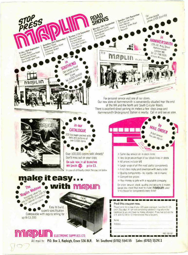
ostt N.\ oxe,e0
PO° nnSk
?cc1,)400, este),00 0.4 159_*
1.7:toe,00""e-
w 0
A160 SeP10`\)ei
tpobetSatoi
uai,1
)14. tez), tinigte23):31P;:ot
Soeselisee-eN,Hovey
G351:oi et \es:sv,,leil:ol
iv% ,sewn: ee
o
Atto cAu pa-70\ SP6kZ
v.\\`'-° p\Ne s v,st*,54,00
n .
ktoopl) ,66,0
P°se'w -
Intomminow...""NNimini
/111
in our
CATALOGUE
320 big pages packed with
me H mmecsmith41.
days)d
o
Ft: TG4,J
Tel 01.748
- =r1Pr
,t.
For personal service visit one of our stores.Our new store at Hammersmith is conveniently situated near the end
of the M4 and the North and South Circular Roads.There is excellent street parking on meters a few steps away and
Hammersmith Underground Station is nearby. Call in and see us soon.
data and pictures of dikover 5 500 items w
Over 100,000 copies sold already!
Don't miss out on your copy.
On sale now in all branches
WH Smith 0 price El.
In case of difficulty check the coupon below.
make it easy...6; ,e,t with fryllarminotoo
ktaP--4,,,a\esoci5 r,s02,,cfp9rooe6 c.:25 el 09,e,C-* ko vc,,W Easy to build,
superb specification.Comparable with organs selling for
up to £1,000.
wo(pitin ELECTRONIC SUPPLIES LID.
All mail to. P.O. Box 3, Rayleigh, Essex SS6 8LR.
seit:service
telY Same day service on in -stock lines
* Very large percentage of our stock lines in stock
All prices include VAT
* Large range of all the most useful components
* First class reply paid envelope with every order
Quality components-no rejects-no re -marks
* Competitive prices
::c Your money is safe with a reputable company .
On price. service, stock, quality and security it makessense now more than ever to make niacin yourtimt choice for components every time!
gm mom no Ns NE tim mi EN EN Nei EN min
Post this coupon now.Please send me a copy of your 320 page catalogue. I enclose (1 25I find. 25p p&p). If l am not completely satisfied I may return thecatalogue to you and have my money refunded. If you live outside the I
" U K. send £1.68 or 12 International Reply Coupons
I
Name
Addre,,,
I
L =11 dmPE -10-81..1
Tel: Southend (0702) 554155 Sales: (0702) 552911