Embed Size (px)
Citation preview
AusNet Transmission Group Pty Ltd
Transmission Revenue Review 2017-2022
Support Document: RWTS Transformer and CB Replacement Planning Report (Public)
Submitted: 30 October 2015
AMS – Electricity Transmission Network
Planning Report Project XC21 Ringwood Terminal Station - Transformer and 66 kV circuit breaker replacement.
Document number AMS 10-306
Issue number 2
Status Final
Approver Jacqui Bridge
Date of approval 14/09/2015

AusNet Services AMS 10-306
Planning Report Project XC21 – RWTS Transformer and 66 kV CB Replacement
ISSUE 2 15/04/2015 3/ 27 UNCONTROLLED WHEN PRINTED
ISSUE/AMENDMENT STATUS
Issue Number
Date
Description Author Approved by
1 7/11/2012 Final. Initial issue S. Lees D. Postlethwaite
2 14/09/2015 Final. Updated scope and cost. S. Lees / H De Beer
J. Bridge
Disclaimer
This template is for generating internal and external document belonging to AusNet Services and may or may not contain all available information on the subject matter this document purports to address.
The information contained in this document is subject to review and AusNet Services may amend this document at any time. Amendments will be indicated in the Amendment Table, but AusNet Services does not undertake to keep this document up to date.
To the maximum extent permitted by law, AusNet Services makes no representation or warranty (express or implied) as to the accuracy, reliability, or completeness of the information contained in this document, or its suitability for any intended purpose. AusNet Services (which, for the purposes of this disclaimer, includes all of its related bodies corporate, its officers, employees, contractors, agents and consultants, and those of its related bodies corporate) shall have no liability for any loss or damage (be it direct or indirect, including liability by reason of negligence or negligent misstatement) for any statements, opinions, information or matter (expressed or implied) arising out of, contained in, or derived from, or for any omissions from, the information in this document.
Contact
This document is the responsibility of AusNet Services.
Please contact the indicated owner of the document with any inquiries. J Bridge
AusNet Services
Level 31, 2 Southbank Boulevard
Melbourne Victoria 3006
Ph: (03) 9695 6000
AusNet Services AMS 10-306
Planning Report Project XC21 – RWTS Transformer and 66 kV CB Replacement
ISSUE 2 15/04/2015 4/ 27 UNCONTROLLED WHEN PRINTED
Table of Contents
1 Executive Summary ..................................................................................................................... 5
1.1 Responsibility .............................................................................................................................................. 5
1.2 Emerging Constraints ................................................................................................................................. 5
1.3 Economic Option ......................................................................................................................................... 5
2 Purpose ......................................................................................................................................... 6
3 Regulatory Obligations and Customer Requirements ............................................................. 6
4 Background .................................................................................................................................. 7
5 Planning Considerations ............................................................................................................. 9
5.1 Planning Responsibilities ............................................................................................................................ 9
5.2 Demand ....................................................................................................................................................... 9
5.3 Future Planning Requirements .................................................................................................................. 9
6 Asset Condition .......................................................................................................................... 11
6.1 220/66 kV Power Transformers ............................................................................................................... 11
6.2 220 kV Circuit Breakers and Current Transformers ................................................................................ 12
6.3 66 kV Circuit Breakers .............................................................................................................................. 12
6.4 66 kV Current transformers ...................................................................................................................... 13
6.5 Secondary Systems .................................................................................................................................. 13
7 Emerging Constraints................................................................................................................ 14
7.1 Safety and Environmental Hazards ......................................................................................................... 14
7.2 Safety, Plant Collateral Damage and Environmental Risk Cost ............................................................. 15
7.3 Reliability and Security of Supply Risk ..................................................................................................... 16
7.4 Baseline Risk ............................................................................................................................................. 18
8 Options to Address Risks ......................................................................................................... 20
9 Evaluation of Options ................................................................................................................ 20
9.1 Option 1: Do Nothing ................................................................................................................................ 20
9.2 Option 2: Non network options of embedded generation and/or demand side response .................... 21
9.3 Option 3: Run to failure ............................................................................................................................. 21
9.4 Option 4: Like for like Replacement ......................................................................................................... 21
9.5 Option 5: Like for like Replacement with upgraded firewalls and gantry ............................................... 22
9.6 Option 6: Like for like Replacement in new location with upgraded firewalls and gantry...................... 22
9.7 PV Analysis ............................................................................................................................................... 22
9.8 Economic Option and economic timing ................................................................................................... 23
9.9 Sensitivity Studies ..................................................................................................................................... 24
10 Scope of Work ............................................................................................................................ 26
AusNet Services AMS 10-306
Planning Report Project XC21 – RWTS Transformer and 66 kV CB Replacement
ISSUE 2 15/04/2015 5/ 27 UNCONTROLLED WHEN PRINTED
1 Executive Summary
1.1 Responsibility
AusNet Transmission Group (AusNet Services) as a Transmission Network Service Provider (TNSP) in the state of Victoria has the ownership, operation and maintenance responsibility for Ringwood Terminal Station (RWTS). TNSP obligations include maintaining a safe working environment for staff and contractors, maintaining the quality, reliability and security of customer supplies, and preventing operating and maintenance costs from escalating to inefficient levels.
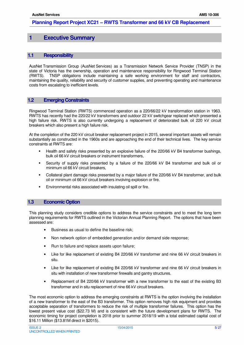
1.2 Emerging Constraints
Ringwood Terminal Station (RWTS) commenced operation as a 220/66/22 kV transformation station in 1963. RWTS has recently had the 220/22 kV transformers and outdoor 22 kV switchgear replaced which presented a high failure risk. RWTS is also currently undergoing a replacement of deteriorated bulk oil 220 kV circuit breakers which also present a high failure risk. At the completion of the 220 kV circuit breaker replacement project in 2015, several important assets will remain substantially as constructed in the 1960s and are approaching the end of their technical lives. The key service constraints at RWTS are:
� Health and safety risks presented by an explosive failure of the 220/66 kV B4 transformer bushings, bulk oil 66 kV circuit breakers or instrument transformers,
� Security of supply risks presented by a failure of the 220/66 kV B4 transformer and bulk oil or minimum oil 66 kV circuit breakers,
� Collateral plant damage risks presented by a major failure of the 220/66 kV B4 transformer, and bulk oil or minimum oil 66 kV circuit breakers involving explosion or fire.
� Environmental risks associated with insulating oil spill or fire.
1.3 Economic Option
This planning study considers credible options to address the service constraints and to meet the long term planning requirements for RWTS outlined in the Victorian Annual Planning Report. The options that have been assessed are:
• Business as usual to define the baseline risk;
• Non network option of embedded generation and/or demand side response;
• Run to failure and replace assets upon failure;
• Like for like replacement of existing B4 220/66 kV transformer and nine 66 kV circuit breakers in
situ.
• Like for like replacement of existing B4 220/66 kV transformer and nine 66 kV circuit breakers in
situ with installation of new transformer firewalls and gantry structures.
• Replacement of B4 220/66 kV transformer with a new transformer to the east of the existing B3
transformer and in situ replacement of nine 66 kV circuit breakers.
The most economic option to address the emerging constraints at RWTS is the option involving the installation of a new transformer to the east of the B3 transformer. This option removes high risk equipment and provides acceptable separation of transformers to reduce the risk of multiple transformer failures. This option has the lowest present value cost ($22.73 M) and is consistent with the future development plans for RWTS. The economic timing for project completion is 2018 prior to summer 2018/19 with a total estimated capital cost of $16.11 Million ($13.81M direct in $2015).
AusNet Services AMS 10-306
Planning Report Project XC21 – RWTS Transformer and 66 kV CB Replacement
ISSUE 2 15/04/2015 6/ 27 UNCONTROLLED WHEN PRINTED
2 Purpose
This planning report outlines asset condition, asset failure risks and network development plans relevant to RWTS for the planning period from 2015/16 to 2022/23. It provides an analysis of viable options to address the identified risks and maintain the efficient delivery of electrical energy from RWTS consistent with the National Electricity Rules (NER) and stakeholder’s requirements. It also summarizes the scope, delivery schedule and expenditures associated with the most economical solution to emerging constraints.
3 Regulatory Obligations and Customer Requirements
This planning report acknowledges AusNet Services’ obligations as a TNSP under the National Electricity Rules with particular emphasis on: Clause 6A.6.7 of the National Electricity Rules requires AusNet Services to propose capital expenditures necessary to: (1) meet or manage the expected demand for prescribed transmission services over that period;
(2) comply with all applicable regulatory obligations or requirements associated with the provision of
prescribed transmission services;
(3) to the extent that there is no applicable regulatory obligation or requirement in relation to:
(i) the quality, reliability or security of supply of prescribed transmission services; or
(ii) the reliability or security of the transmission system through the supply of prescribed transmission
services,
to the relevant extent:
(iii) maintain the quality, reliability and security of supply of prescribed transmission services; and
(iv) maintain the reliability and security of the transmission system through the supply of prescribed
transmission services; and
(4) maintain the safety of the transmission system through the supply of prescribed transmission services.
The Electricity Safety Act (section 98(a)) requires AusNet Services to “design, construct, operate, maintain and decommission its supply network to minimise the hazards and risks, so far as is practicable, to the safety of any person arising from the supply network; having regard to the:
a) severity of the hazard or risk in question; and
b) state of knowledge about the hazard or risk and any ways of removing or mitigating the hazard or
risk; and
c) availability and suitability of ways to remove or mitigate the hazard or risk; and
d) cost of removing or mitigating the hazard or risk”.
AusNet Services AMS 10-306
Planning Report Project XC21 – RWTS Transformer and 66 kV CB Replacement
ISSUE 2 15/04/2015 7/ 27 UNCONTROLLED WHEN PRINTED
4 Background
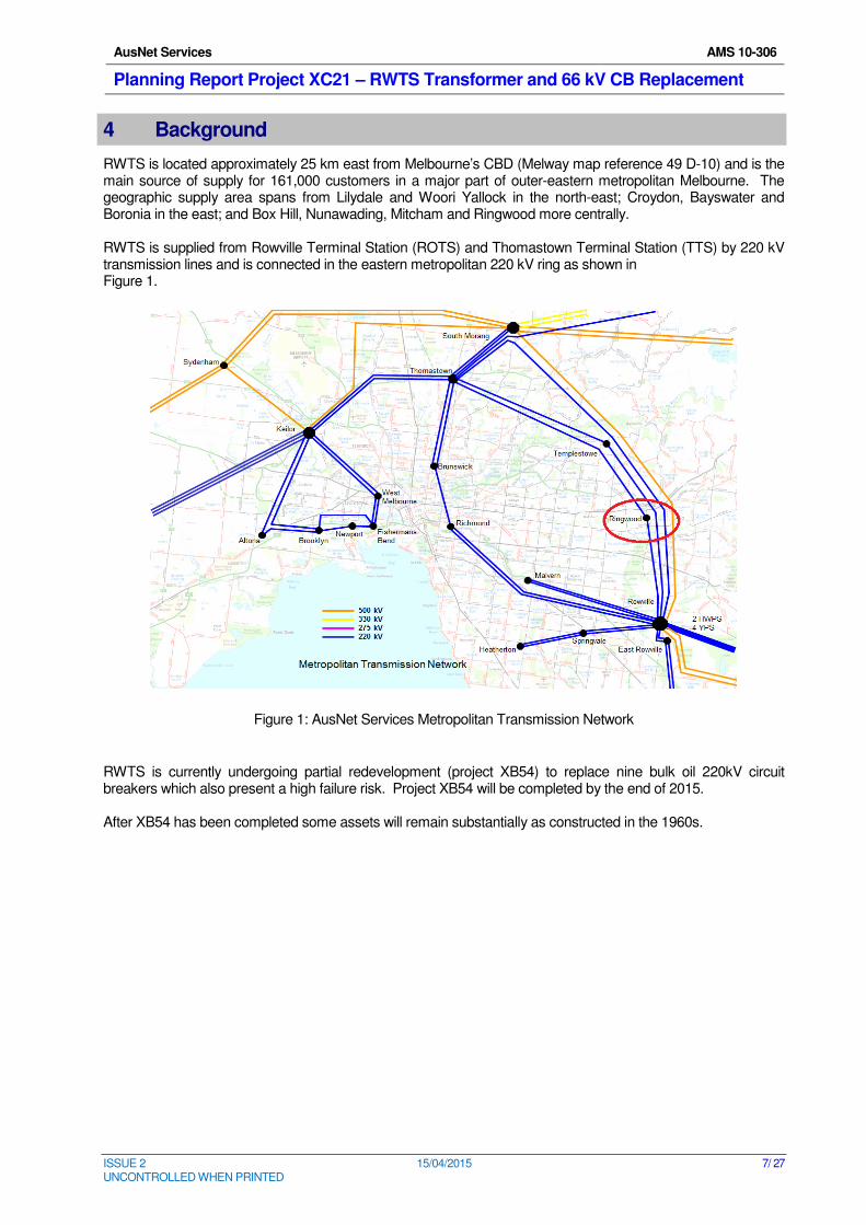
RWTS is located approximately 25 km east from Melbourne’s CBD (Melway map reference 49 D-10) and is the main source of supply for 161,000 customers in a major part of outer-eastern metropolitan Melbourne. The geographic supply area spans from Lilydale and Woori Yallock in the north-east; Croydon, Bayswater and Boronia in the east; and Box Hill, Nunawading, Mitcham and Ringwood more centrally. RWTS is supplied from Rowville Terminal Station (ROTS) and Thomastown Terminal Station (TTS) by 220 kV transmission lines and is connected in the eastern metropolitan 220 kV ring as shown in Figure 1.
Figure 1: AusNet Services Metropolitan Transmission Network
RWTS is currently undergoing partial redevelopment (project XB54) to replace nine bulk oil 220kV circuit breakers which also present a high failure risk. Project XB54 will be completed by the end of 2015. After XB54 has been completed some assets will remain substantially as constructed in the 1960s.
AusNet Services AMS 10-306
Planning Report Project XC21 – RWTS Transformer and 66 kV CB Replacement
ISSUE 2 15/04/2015 8/ 27 UNCONTROLLED WHEN PRINTED
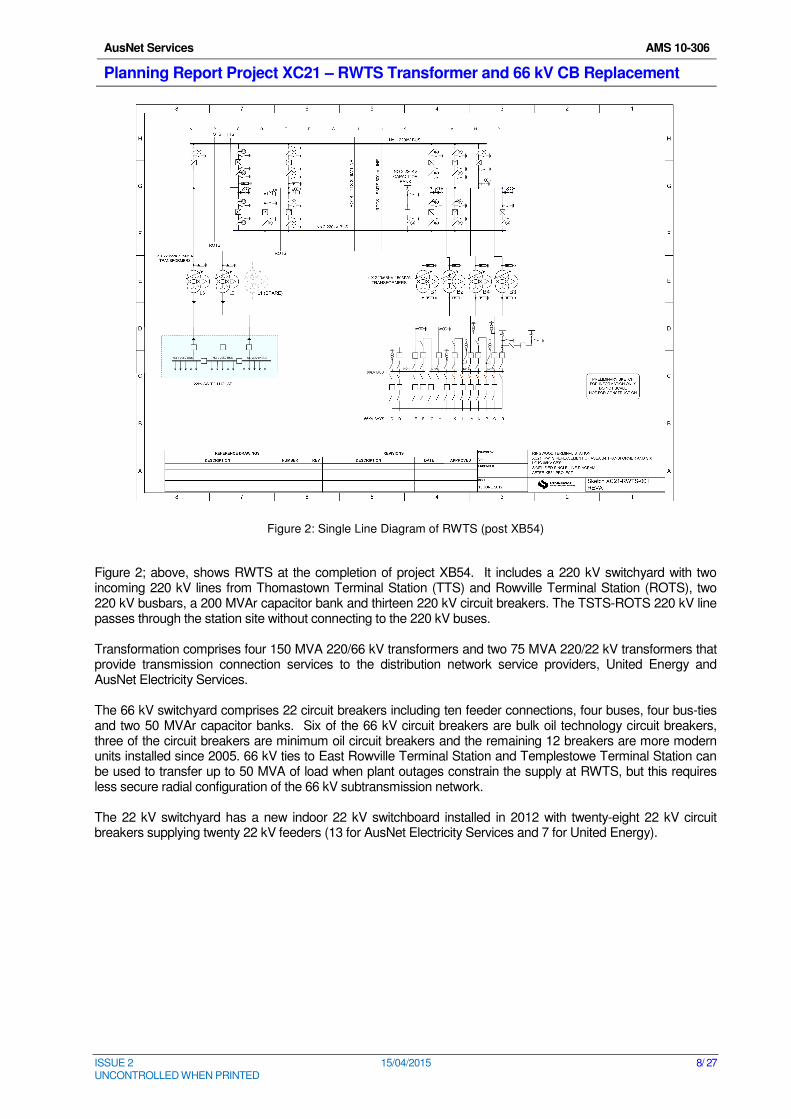
Figure 2: Single Line Diagram of RWTS (post XB54)
Figure 2; above, shows RWTS at the completion of project XB54. It includes a 220 kV switchyard with two incoming 220 kV lines from Thomastown Terminal Station (TTS) and Rowville Terminal Station (ROTS), two 220 kV busbars, a 200 MVAr capacitor bank and thirteen 220 kV circuit breakers. The TSTS-ROTS 220 kV line passes through the station site without connecting to the 220 kV buses. Transformation comprises four 150 MVA 220/66 kV transformers and two 75 MVA 220/22 kV transformers that provide transmission connection services to the distribution network service providers, United Energy and AusNet Electricity Services. The 66 kV switchyard comprises 22 circuit breakers including ten feeder connections, four buses, four bus-ties and two 50 MVAr capacitor banks. Six of the 66 kV circuit breakers are bulk oil technology circuit breakers, three of the circuit breakers are minimum oil circuit breakers and the remaining 12 breakers are more modern units installed since 2005. 66 kV ties to East Rowville Terminal Station and Templestowe Terminal Station can be used to transfer up to 50 MVA of load when plant outages constrain the supply at RWTS, but this requires less secure radial configuration of the 66 kV subtransmission network.
The 22 kV switchyard has a new indoor 22 kV switchboard installed in 2012 with twenty-eight 22 kV circuit breakers supplying twenty 22 kV feeders (13 for AusNet Electricity Services and 7 for United Energy).
AusNet Services AMS 10-306
Planning Report Project XC21 – RWTS Transformer and 66 kV CB Replacement
ISSUE 2 15/04/2015 9/ 27 UNCONTROLLED WHEN PRINTED
5 Planning Considerations
5.1 Planning Responsibilities
The augmentation responsibility for RWTS lies with the Australian Energy Market Operator (AEMO) for the shared transmission network and with the distributors, AusNet Electricity Services and United Energy, for the transmission connection assets.
5.2 Demand
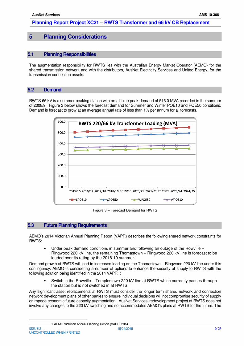
RWTS 66 kV is a summer peaking station with an all-time peak demand of 516.0 MVA recorded in the summer of 2008/9. Figure 3 below shows the forecast demand for Summer and Winter POE10 and POE50 conditions. Demand is forecast to grow at an average annual rate of less than 1% per annum for all forecasts.
Figure 3 – Forecast Demand for RWTS
5.3 Future Planning Requirements
AEMO’s 2014 Victorian Annual Planning Report (VAPR) describes the following shared network constraints for RWTS:
• Under peak demand conditions in summer and following an outage of the Rowville – Ringwood 220 kV line, the remaining Thomastown – Ringwood 220 kV line is forecast to be loaded over its rating by the 2018-19 summer.
Demand growth at RWTS will lead to increased loading on the Thomastown – Ringwood 220 kV line under this contingency. AEMO is considering a number of options to enhance the security of supply to RWTS with the following solution being identified in the 2014 VAPR
1:
• Switch in the Rowville – Templestowe 220 kV line at RWTS which currently passes through the station but is not switched in at RWTS.
Any significant asset replacements at RWTS must consider the longer term shared network and connection network development plans of other parties to ensure individual decisions will not compromise security of supply or impede economic future capacity augmentation. AusNet Services’ redevelopment project at RWTS does not involve any changes to the 220 kV switching and so accommodates AEMO’s plans at RWTS for the future. The
1 AEMO Victorian Annual Planning Report (VAPR) 2014.
AusNet Services AMS 10-306
Planning Report Project XC21 – RWTS Transformer and 66 kV CB Replacement
ISSUE 2 15/04/2015 10/ 27 UNCONTROLLED WHEN PRINTED
current XB54 project involving the replacement of the 220 kV circuit breakers has taken this requirement into account. The distributor’s future plans for RWTS include the following:
� Five 150 MVA 220/66 kV transformers
� Three 75 MVA 220/22 kV transformers
� Provision for two more 66 kV feeders for a total of twelve feeders
� Provision for six more 22 kV feeders for a total of twenty six feeders
The proposed works at RWTS are consistent with these requirements.
AusNet Services AMS 10-306
Planning Report Project XC21 – RWTS Transformer and 66 kV CB Replacement
ISSUE 2 15/04/2015 11/ 27 UNCONTROLLED WHEN PRINTED
6 Asset Condition
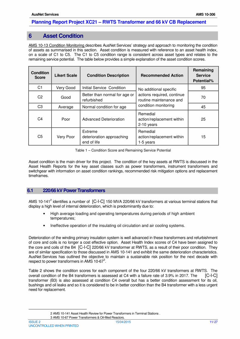
AMS 10-13 Condition Monitoring describes AusNet Services’ strategy and approach to monitoring the condition of assets as summarised in this section. Asset condition is measured with reference to an asset health index, on a scale of C1 to C5. The C1 to C5 condition range is consistent across asset types and relates to the remaining service potential. The table below provides a simple explanation of the asset condition scores.
Condition Score
Likert Scale Condition Description Recommended Action
Remaining
Service
Potential%
C1 Very Good Initial Service Condition No additional specific
actions required, continue
routine maintenance and
condition monitoring
95
C2 Good Better than normal for age or
refurbished 70
C3 Average Normal condition for age 45
C4 Poor Advanced Deterioration
Remedial
action/replacement within
2-10 years
25
C5 Very Poor
Extreme
deterioration approaching
end of life
Remedial
action/replacement within
1-5 years
15
Table 1 – Condition Score and Remaining Service Potential
Asset condition is the main driver for this project. The condition of the key assets at RWTS is discussed in the Asset Health Reports for the key asset classes such as power transformers, instrument transformers and switchgear with information on asset condition rankings, recommended risk mitigation options and replacement timeframes.
6.1 220/66 kV Power Transformers
AMS 10-1412 identifies a number of [C-I-C] 150 MVA 220/66 kV transformers at various terminal stations that
display a high level of internal deterioration, which is predominantly due to:
• High average loading and operating temperatures during periods of high ambient temperatures;
• Ineffective operation of the insulating oil circulation and air cooling systems.
Deterioration of the winding primary insulation system is well advanced in these transformers and refurbishment of core and coils is no longer a cost effective option. Asset Health Index scores of C4 have been assigned to
the core and coils of the B4 [C-I-C] 220/66 kV transformer at RWTS, as a result of their poor condition. They are of similar specification to those discussed in AMS 10-141 and exhibit the same deterioration characteristics. AusNet Services has outlined the objective to maintain a sustainable risk position for the next decade with respect to power transformers in AMS 10-67
3.
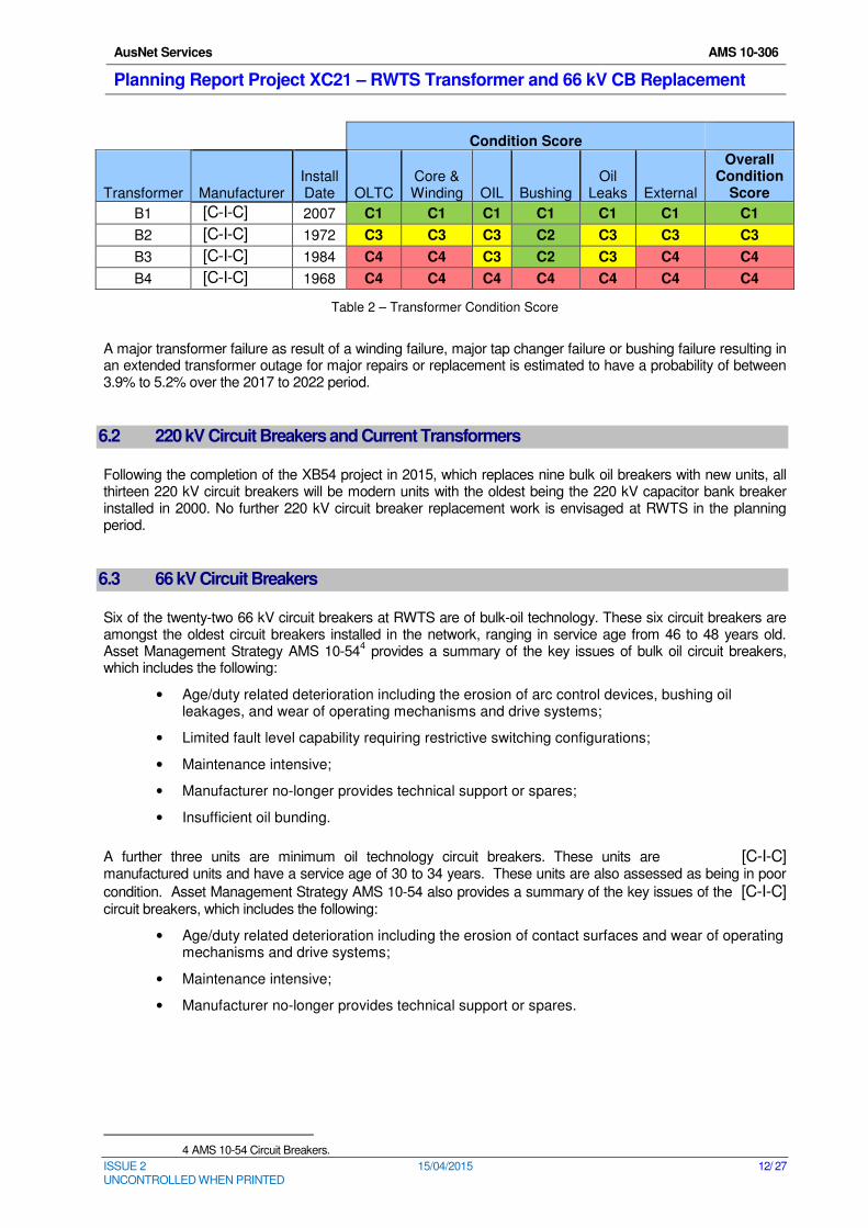
Table 2 shows the condition scores for each component of the four 220/66 kV transformers at RWTS. The
overall condition of the B4 transformers is assessed at C4 with a failure rate of 3.9% in 2017. The [C-I-C] transformer (B3) is also assessed at condition C4 overall but has a better condition assessment for its oil, bushings and oil leaks and so it is considered to be in better condition than the B4 transformer with a less urgent need for replacement.
2 AMS 10-141 Asset Health Review for Power Transformers in Terminal Stations .
3 AMS 10-67 Power Transformers & Oil-filled Reactors.
AusNet Services AMS 10-306
Planning Report Project XC21 – RWTS Transformer and 66 kV CB Replacement
ISSUE 2 15/04/2015 12/ 27 UNCONTROLLED WHEN PRINTED
Condition Score
Transformer Manufacturer Install Date OLTC
Core & Winding OIL Bushing
Oil Leaks External
Overall Condition
Score
B1 [C-I-C] 2007 C1 C1 C1 C1 C1 C1 C1
B2 [C-I-C] 1972 C3 C3 C3 C2 C3 C3 C3
B3 [C-I-C] 1984 C4 C4 C3 C2 C3 C4 C4
B4 [C-I-C] 1968 C4 C4 C4 C4 C4 C4 C4
Table 2 – Transformer Condition Score
A major transformer failure as result of a winding failure, major tap changer failure or bushing failure resulting in an extended transformer outage for major repairs or replacement is estimated to have a probability of between 3.9% to 5.2% over the 2017 to 2022 period.
6.2 220 kV Circuit Breakers and Current Transformers
Following the completion of the XB54 project in 2015, which replaces nine bulk oil breakers with new units, all thirteen 220 kV circuit breakers will be modern units with the oldest being the 220 kV capacitor bank breaker installed in 2000. No further 220 kV circuit breaker replacement work is envisaged at RWTS in the planning period.
6.3 66 kV Circuit Breakers
Six of the twenty-two 66 kV circuit breakers at RWTS are of bulk-oil technology. These six circuit breakers are amongst the oldest circuit breakers installed in the network, ranging in service age from 46 to 48 years old. Asset Management Strategy AMS 10-54
4 provides a summary of the key issues of bulk oil circuit breakers,
which includes the following:
• Age/duty related deterioration including the erosion of arc control devices, bushing oil leakages, and wear of operating mechanisms and drive systems;
• Limited fault level capability requiring restrictive switching configurations;
• Maintenance intensive;
• Manufacturer no-longer provides technical support or spares;
• Insufficient oil bunding.
A further three units are minimum oil technology circuit breakers. These units are [C-I-C] manufactured units and have a service age of 30 to 34 years. These units are also assessed as being in poor
condition. Asset Management Strategy AMS 10-54 also provides a summary of the key issues of the [C-I-C] circuit breakers, which includes the following:
• Age/duty related deterioration including the erosion of contact surfaces and wear of operating mechanisms and drive systems;
• Maintenance intensive;
• Manufacturer no-longer provides technical support or spares.
4 AMS 10-54 Circuit Breakers.
AusNet Services AMS 10-306
Planning Report Project XC21 – RWTS Transformer and 66 kV CB Replacement
ISSUE 2 15/04/2015 13/ 27 UNCONTROLLED WHEN PRINTED
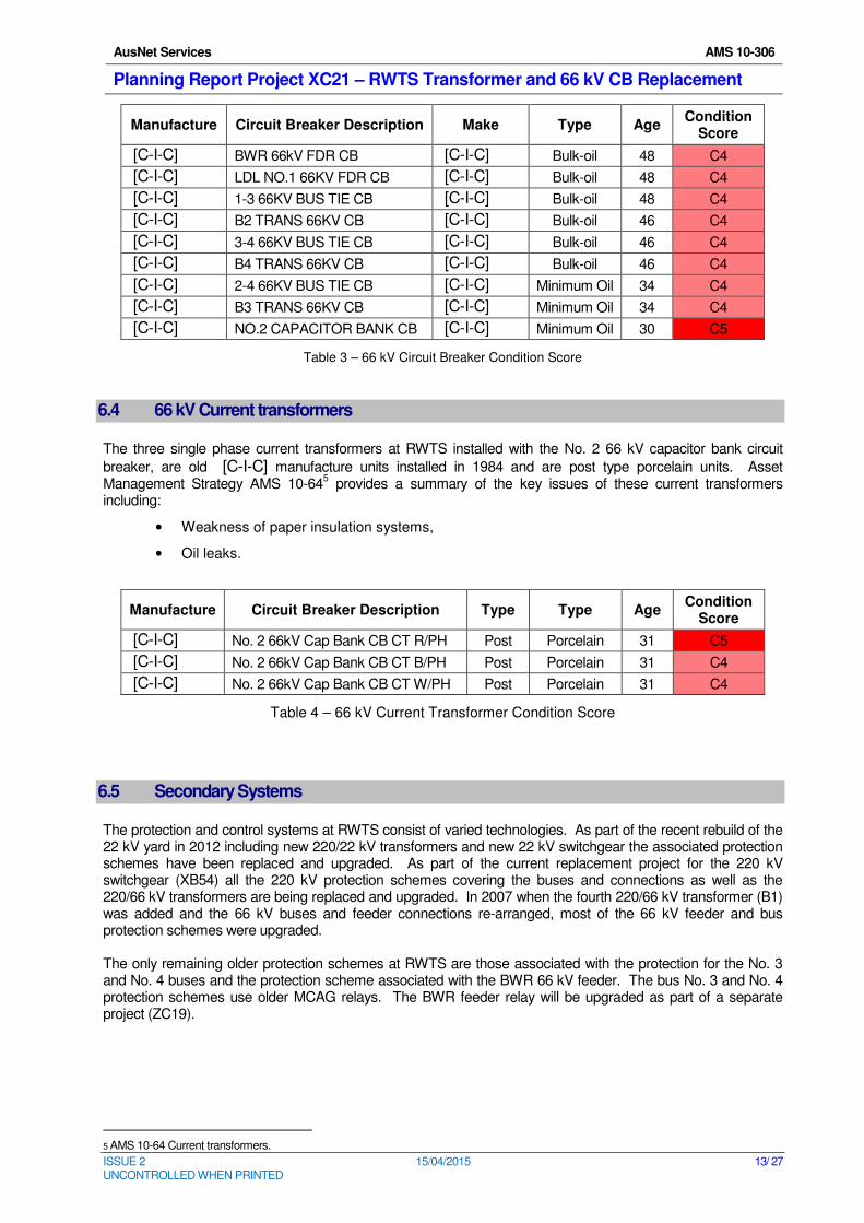
Manufacture Circuit Breaker Description Make Type Age Condition
Score
[C-I-C] BWR 66kV FDR CB [C-I-C] Bulk-oil 48 C4
[C-I-C] LDL NO.1 66KV FDR CB [C-I-C] Bulk-oil 48 C4
[C-I-C] 1-3 66KV BUS TIE CB [C-I-C] Bulk-oil 48 C4
[C-I-C] B2 TRANS 66KV CB [C-I-C] Bulk-oil 46 C4
[C-I-C] 3-4 66KV BUS TIE CB [C-I-C] Bulk-oil 46 C4
[C-I-C] B4 TRANS 66KV CB [C-I-C] Bulk-oil 46 C4
[C-I-C] 2-4 66KV BUS TIE CB [C-I-C] Minimum Oil 34 C4
[C-I-C] B3 TRANS 66KV CB [C-I-C] Minimum Oil 34 C4
[C-I-C] NO.2 CAPACITOR BANK CB [C-I-C] Minimum Oil 30 C5
Table 3 – 66 kV Circuit Breaker Condition Score
6.4 66 kV Current transformers
The three single phase current transformers at RWTS installed with the No. 2 66 kV capacitor bank circuit
breaker, are old [C-I-C] manufacture units installed in 1984 and are post type porcelain units. Asset Management Strategy AMS 10-64
5 provides a summary of the key issues of these current transformers
including:
• Weakness of paper insulation systems,
• Oil leaks.
Manufacture Circuit Breaker Description Type Type Age Condition
Score
[C-I-C] No. 2 66kV Cap Bank CB CT R/PH Post Porcelain 31 C5
[C-I-C] No. 2 66kV Cap Bank CB CT B/PH Post Porcelain 31 C4
[C-I-C] No. 2 66kV Cap Bank CB CT W/PH Post Porcelain 31 C4
Table 4 – 66 kV Current Transformer Condition Score
6.5 Secondary Systems
The protection and control systems at RWTS consist of varied technologies. As part of the recent rebuild of the 22 kV yard in 2012 including new 220/22 kV transformers and new 22 kV switchgear the associated protection schemes have been replaced and upgraded. As part of the current replacement project for the 220 kV switchgear (XB54) all the 220 kV protection schemes covering the buses and connections as well as the 220/66 kV transformers are being replaced and upgraded. In 2007 when the fourth 220/66 kV transformer (B1) was added and the 66 kV buses and feeder connections re-arranged, most of the 66 kV feeder and bus protection schemes were upgraded. The only remaining older protection schemes at RWTS are those associated with the protection for the No. 3 and No. 4 buses and the protection scheme associated with the BWR 66 kV feeder. The bus No. 3 and No. 4 protection schemes use older MCAG relays. The BWR feeder relay will be upgraded as part of a separate project (ZC19).
5 AMS 10-64 Current transformers.
AusNet Services AMS 10-306
Planning Report Project XC21 – RWTS Transformer and 66 kV CB Replacement
ISSUE 2 15/04/2015 14/ 27 UNCONTROLLED WHEN PRINTED
7 Emerging Constraints
The key service constraints and monetised risk identified for the aging and deteriorated assets at RWTS are described in this section.
7.1 Safety and Environmental Hazards
7.1.1 Transformers
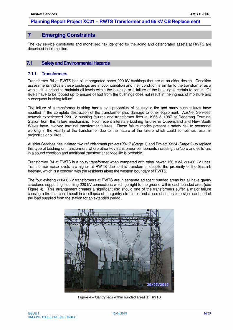
Transformer B4 at RWTS has oil impregnated paper 220 kV bushings that are of an older design. Condition assessments indicate these bushings are in poor condition and their condition is similar to the transformer as a whole. It is critical to maintain oil levels within the bushing or a failure of the bushing is certain to occur. Oil levels have to be topped up to ensure oil lost from the bushings does not result in the ingress of moisture and subsequent bushing failure. The failure of a transformer bushing has a high probability of causing a fire and many such failures have resulted in the complete destruction of the transformer plus damage to other equipment. AusNet Services’ network experienced 220 kV bushing failures and transformer fires in 1965 & 1987 at Dederang Terminal Station from this failure mechanism. Four recent interstate bushing failures in Queensland and New South Wales have involved terminal transformer failures. These failure modes present a safety risk to personnel working in the vicinity of the transformer due to the nature of the failure which could sometimes result in projectiles or oil fires. AusNet Services has initiated two refurbishment projects X417 (Stage 1) and Project X834 (Stage 2) to replace this type of bushing on transformers where other key transformer components including the ‘core and coils’ are in a sound condition and additional transformer service life is probable. Transformer B4 at RWTS is a noisy transformer when compared with other newer 150 MVA 220/66 kV units. Transformer noise levels are higher at RWTS due to this transformer despite the proximity of the Eastlink freeway, which is a concern with the residents along the western boundary of RWTS. The four existing 220/66 kV transformers at RWTS are in separate adjacent bunded areas but all have gantry structures supporting incoming 220 kV connections which go right to the ground within each bunded area (see Figure 4). This arrangement creates a significant risk should one of the transformers suffer a major failure causing a fire that could result in a collapse of the gantry structures and a loss of supply to a significant part of the load supplied from the station for an extended period.
Figure 4 – Gantry legs within bunded areas at RWTS
AusNet Services AMS 10-306
Planning Report Project XC21 – RWTS Transformer and 66 kV CB Replacement
ISSUE 2 15/04/2015 15/ 27 UNCONTROLLED WHEN PRINTED
7.1.2 Circuit Breakers
Six of the 66 kV circuit breakers at RWTS are bulk oil technology circuit breakers. They have generally provided reliable service, but are approaching the end of their technical lives.
As described in AMS 10-54 Circuit Breakers, bulk oil circuit breakers are expensive to maintain in comparison with the modern equivalent. Their failure modes can include explosion and fire. Due to the large volume of insulating oil within the tanks and the high voltage bushings, failures could potentially cause collateral damage to adjacent high voltage plant, cable trenches, secondary cabling and secondary system functionality. Spillage of oil also poses environmental hazards as bulk oil circuit breakers are not positioned within a bunded area.
Three of the 66 kV circuit breakers at RWTS are [C-I-C] minimum oil technology circuit breakers. They have generally provided reliable service, but are also in poor condition and approaching the end of their technical lives.
7.1.3 Current Transformers
As described in AMS 10-64 Instrument Transformers, several explosive failures6 have confirmed that
deteriorated single-phase, porcelain clad, oil insulated current transformers present an unacceptable risk. This risk includes supply outages, collateral plant damage, environment damage and possible injury to personnel. A progressive replacement with toroidal current transformers incorporated within plant such as dead tank circuit breakers is part of AusNet Services’ asset management strategy to address these risks.
There are three [C-I-C] post type porcelain current transformers in the RWTS 66 kV switchyard. It has been ascertained that some of these current transformers are exhibiting thermal and partial discharge issues and declining Dissolved Gas Analysis (DGA) test results.
7.2 Safety, Plant Collateral Damage and Environmental Risk Cost
The Electricity Safety Act requires AusNet Services to design, construct, operate, maintain and decommission its supply network to minimize hazards and risks, so far as is practicable, to the safety of any person arising from the supply network. In practice this means safety risk should be proactively managed until the cost becomes disproportionate to the benefits. With respect to the management of safety risks that may cause a single fatality amongst a crew of
workers; application of the principle of “so far as is practicable” indicates costs in excess of $ [C-I-C] may be disproportionate. The following assumptions were used to calculate the monetise safety, plant collateral damage and environmental hazards presented by the plant described in Section 7.1; consistent with the methodology described in AMS 10-24 Victorian Electricity Transmission Network – Asset Renewal Planning Guideline:
• An explosive failure or oil fire could injure or kill workers on site with an economic
consequence cost of $ [C-I-C] ;
• Plant that contains large volumes of oil poses an environmental risk with an average
consequence cost of $30k per event;
• Transformer with oil that contains poly-chlorinated biphenyls (PCB) poses an environmental
risk with an average consequence cost of $100k per event;
• Plant collateral damage, including consequent supply outages, is on average $1.0 M per
event.
The likelihood of the above hazards occurring at RWTS have been calculated from the major failure rates in the circuit breaker, current transformer and power transformer reliability centred maintenance (RCM) models and the CIGRE research into the probability of explosion and fire associated with major plant failures
7.
6 Moorabool Terminal Station 2002 & 2005, Jeeralang Terminal Station 2003, Ballarat Terminal Station 2006 and Terang
Terminal Station 2006.
7 Cigre Final Report of the 2004 – 2007 International Enquiry on Reliability of High Voltage Equipment.
AusNet Services AMS 10-306
Planning Report Project XC21 – RWTS Transformer and 66 kV CB Replacement
ISSUE 2 15/04/2015 16/ 27 UNCONTROLLED WHEN PRINTED
Figure 5 shows the expected safety, plant collateral damage and environmental risk cost at RWTS based on the following risks:
• Health and safety risk due to a power transformer bushing, current transformer or bulk oil
circuit breaker explosive failure;
• Environmental risk presented by insulating oil spillage;
• Collateral damage to adjacent plant due to catastrophic failure of bulk oil circuit breakers or
current transformers.
[C-I-C]
Figure 5 – Expected Annual Safety, Plant Collateral Damage and Environmental Risk Cost
7.3 Reliability and Security of Supply Risk
7.3.1 220 kV Switchyard
Following the completion of the XB54 project in 2015 which replaces nine bulk oil circuit breakers with new units the station will have a fully switched configuration supported by circuit breakers which are all in good condition. Supply security risks will be at low and acceptable levels.
7.3.2 66 kV Switchyard
Six of the 66 kV circuit breakers at RWTS are bulk oil technology circuit breakers and three of the 66 kV circuit breakers are minimum oil technology. The consequences of a bulk oil or minimum oil circuit breaker failure include:
• A failure of the 1-3 bus tie circuit breaker would most likely cause a total loss of supply to both 66 kV buses resulting in the loss of supply for bus group 1-3 involving five zone substations and 92,000 customers. It could take up to 2 hours to isolate the failed circuit breaker and to restore the supply resulting in a major disruption to supply during this time.
• A failure of the 2-4 bus tie circuit breaker would most likely cause a total loss of supply to both 66 kV buses resulting in the loss of supply for bus group 2-4 involving three zone substations and 69,000 customers. It could take up to 2 hours to isolate the failed circuit breaker and to restore the supply resulting in a major disruption to supply during this time
• A failure of the B2 and B4 Transformer circuit breakers would result in un-availability of that transformer for a period of at least 4 days. This would place some load at risk for an outage during a period of high demand.
AusNet Services AMS 10-306
Planning Report Project XC21 – RWTS Transformer and 66 kV CB Replacement
ISSUE 2 15/04/2015 17/ 27 UNCONTROLLED WHEN PRINTED
• A failure of the B3 Transformer circuit breaker would result in un-availability of that transformer for a period of at least 4 days. This would place some load at risk for an outage during a period of high demand.
• The bus tie between bus 3 and bus 4 is a bulk oil circuit breaker which is normally open under normal station configuration. In the event that this circuit breaker is required to close for an outage of another 66 kV bus or transformer this circuit breaker is prone to failure on closure which would result in loss of supply to both 66 kV buses. There is however a newer bus tie circuit breaker that ties bus No.1 and 2 that could also be closed to restore supply to all 66 kV feeders so the supply risk for this circuit breaker is low.
• The Bayswater and Lilydale No. 1 66 kV feeders are bulk oil circuit breakers and a failure of either of these circuit breakers would result in this feeder being un-available for a period of at least 4 days. This would place considerable 66 kV load at a greater risk of being lost should a further 66 kV line outage occur. Both the 66 kV loops to LDL and BWR will be reinforced with a third 66 kV line prior to 2015 so the risk for these outages is low.
• The No. 2 capacitor bank circuit breaker could fail resulting in loss of the capacitor bank but this would only increase the station loading marginally as a result of poorer power factor so the supply risk for this circuit breaker is low.
7.3.3 220/66 kV transformers
A major failure of the 220/66 kV transformers presents a risk to supplies from RWTS. This risk will increase over time as the condition of the 220/66 kV transformers deteriorates and the failure risk increases. The transformer failure risk model indicates that the annual probability of a major failure of the B4 and B3 transformers is 3.9% in 2017 but will rise to 5.2% by 2022. A failure of one of these transformers would result in the station operating with only three transformers for up to three months while the transformer is repaired or replaced with a spare transformer. The consequence of a coincident failure of two transformers will be significant. This scenario could happen if one transformer is lost and a failure of the remaining unit occurs before the first unit can be replaced. It will result in a significant disruption to customers supplied from RWTS as only two transformers will be available.
7.3.4 Gantry’s for connection of 220 kV supply to 220/66 kV transformers
The current configuration for the 220 kV connections gantry, which has tower legs within each bund also represents a risk of gantry failure resulting in loss of supply to a significant part of the load supplied from the station for a period of up to 12 hours following a transformer fire.
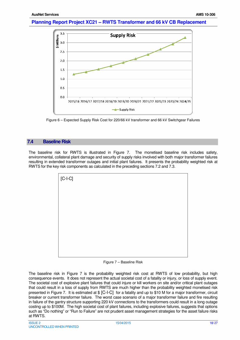
7.3.5 Expected Supply Risk
Figure 6 shows the expected supply risk cost associated with 66 kV switchgear and 220/66 kV transformer failures.
AusNet Services AMS 10-306
Planning Report Project XC21 – RWTS Transformer and 66 kV CB Replacement
ISSUE 2 15/04/2015 18/ 27 UNCONTROLLED WHEN PRINTED
Figure 6 – Expected Supply Risk Cost for 220/66 kV transformer and 66 kV Switchgear Failures
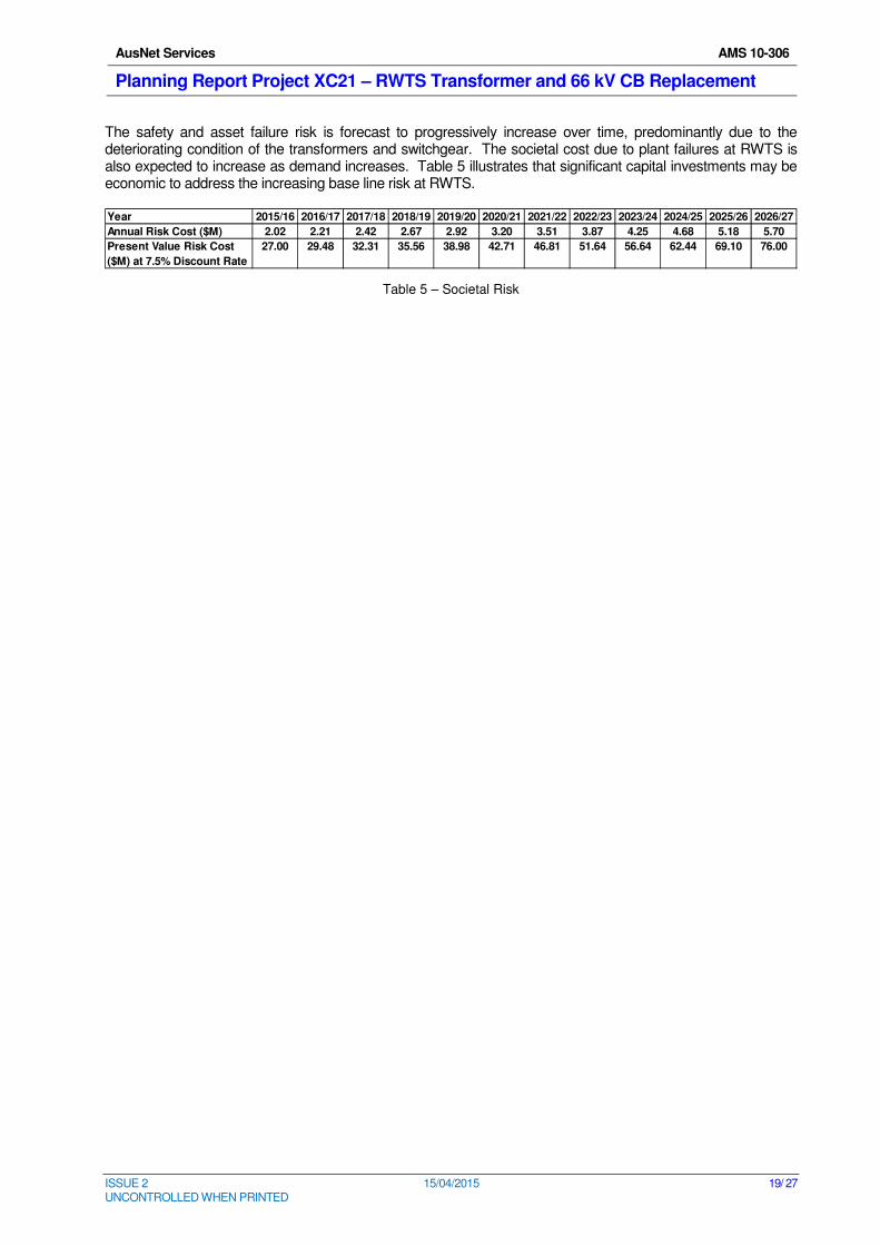
7.4 Baseline Risk
The baseline risk for RWTS is illustrated in Figure 7. The monetised baseline risk includes safety, environmental, collateral plant damage and security of supply risks involved with both major transformer failures resulting in extended transformer outages and initial plant failures. It presents the probability weighted risk at RWTS for the key risk components as calculated in the preceding sections 7.2 and 7.3.
[C-I-C]
Figure 7 – Baseline Risk
The baseline risk in Figure 7 is the probability weighted risk cost at RWTS of low probability, but high consequence events. It does not represent the actual societal cost of a fatality or injury, or loss of supply event. The societal cost of explosive plant failures that could injure or kill workers on site and/or critical plant outages that could result in a loss of supply from RWTS are much higher than the probability weighted monetised risk
presented in Figure 7. It is estimated at $ [C-I-C] for a fatality and up to $10 M for a major transformer, circuit breaker or current transformer failure. The worst case scenario of a major transformer failure and fire resulting in failure of the gantry structure supporting 220 kV connections to the transformers could result in a long outage costing up to $100M. The high societal cost of plant failures, including explosive failures, suggests that options such as “Do nothing” or “Run to Failure” are not prudent asset management strategies for the asset failure risks at RWTS.
AusNet Services AMS 10-306
Planning Report Project XC21 – RWTS Transformer and 66 kV CB Replacement
ISSUE 2 15/04/2015 19/ 27 UNCONTROLLED WHEN PRINTED
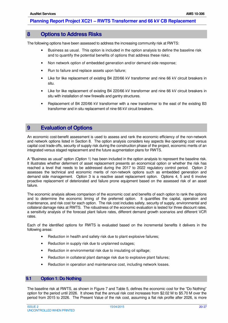
The safety and asset failure risk is forecast to progressively increase over time, predominantly due to the deteriorating condition of the transformers and switchgear. The societal cost due to plant failures at RWTS is also expected to increase as demand increases. Table 5 illustrates that significant capital investments may be economic to address the increasing base line risk at RWTS.
Table 5 – Societal Risk
Year 2015/16 2016/17 2017/18 2018/19 2019/20 2020/21 2021/22 2022/23 2023/24 2024/25 2025/26 2026/27
Annual Risk Cost ($M) 2.02 2.21 2.42 2.67 2.92 3.20 3.51 3.87 4.25 4.68 5.18 5.70
Present Value Risk Cost 27.00 29.48 32.31 35.56 38.98 42.71 46.81 51.64 56.64 62.44 69.10 76.00
($M) at 7.5% Discount Rate
AusNet Services AMS 10-306
Planning Report Project XC21 – RWTS Transformer and 66 kV CB Replacement
ISSUE 2 15/04/2015 20/ 27 UNCONTROLLED WHEN PRINTED
8 Options to Address Risks
The following options have been assessed to address the increasing community risk at RWTS:
• Business as usual. This option is included in the option analysis to define the baseline risk
and to quantify the potential benefits of options that address these risks;
• Non network option of embedded generation and/or demand side response;
• Run to failure and replace assets upon failure;
• Like for like replacement of existing B4 220/66 kV transformer and nine 66 kV circuit breakers in
situ.
• Like for like replacement of existing B4 220/66 kV transformer and nine 66 kV circuit breakers in
situ with installation of new firewalls and gantry structures.
• Replacement of B4 220/66 kV transformer with a new transformer to the east of the existing B3
transformer and in situ replacement of nine 66 kV circuit breakers.
9 Evaluation of Options
An economic cost-benefit assessment is used to assess and rank the economic efficiency of the non-network and network options listed in Section 8. The option analysis considers key aspects like operating cost versus capital cost trade-offs, security of supply risk during the construction phase of the project, economic merits of an integrated versus staged replacement and the future augmentation plans for RWTS. A “Business as usual” option (Option 1) has been included in the option analysis to represent the baseline risk. It illustrates whether deferment of asset replacement presents an economical option or whether the risk has reached a level that needs to be addressed during the 2017 to 2022 regulatory control period. Option 2 assesses the technical and economic merits of non-network options such as embedded generation and demand side management. Option 3 is a reactive asset replacement option. Options 4, 5 and 6 involve proactive replacement of deteriorated and failure prone equipment based on the assessed risk of an asset failure. The economic analysis allows comparison of the economic cost and benefits of each option to rank the options and to determine the economic timing of the preferred option. It quantifies the capital, operation and maintenance, and risk cost for each option. The risk cost includes safety, security of supply, environmental and collateral damage risks at RWTS. The robustness of the economic evaluation is tested for three discount rates, a sensitivity analysis of the forecast plant failure rates, different demand growth scenarios and different VCR rates. Each of the identified options for RWTS is evaluated based on the incremental benefits it delivers in the following areas:
• Reduction in health and safety risk due to plant explosive failures;
• Reduction in supply risk due to unplanned outages;
• Reduction in environmental risk due to insulating oil spillage;
• Reduction in collateral plant damage risk due to explosive plant failures;
• Reduction in operation and maintenance cost, including network losses.
9.1 Option 1: Do Nothing
The baseline risk at RWTS, as shown in Figure 7 and Table 5, defines the economic cost for the “Do Nothing” option for the period until 2026. It shows that the annual risk cost increases from $2.02 M to $5.70 M over the period from 2015 to 2026. The Present Value of the risk cost, assuming a flat risk profile after 2026, is more
AusNet Services AMS 10-306
Planning Report Project XC21 – RWTS Transformer and 66 kV CB Replacement
ISSUE 2 15/04/2015 21/ 27 UNCONTROLLED WHEN PRINTED
than $56.2 M8. This suggests that a “Do Nothing” approach would not be an economical option or a prudent
management strategy for the assets at RWTS. The progressive reduction in reliability of supply and increase in safety risk is inconsistent with AusNet Services’ obligations under the National Electricity Rules. Recurring asset failures is furthermore inconsistent with the requirements of the Electricity Safety Act and AusNet Services’ accepted Electricity Safety Management Scheme. This option is used in the economic evaluation as a reference to measure the economic benefits of options that mitigate the identified risks at RWTS and to ascertain the economical time
9 for a particular option to proceed.
9.2 Option 2: Non network options of embedded generation and/or demand side response
RWTS has energy at risk only under the 10% POE forecast extreme hot summer days conditions based on the current demand forecast for the planning period from 2015 to 2025. The economic benefits of non-network options are hence limited over the planning period and insufficient to warrant further analysis of this option based on typical costs for non-network options. Non network options cannot address the safety risk or meet the full supply requirements at RWTS.
9.3 Option 3: Run to failure
This option involves replacing assets upon failure, which poses a significant risk to the community. The community costs that would result from applying an asset management strategy to only replace an asset after the asset has failed is as follows:
• Up to $100 M for a major transformer fire and gantry failure.
• $10 M for key bus-tie circuit breaker failure
Some of the plant (transformer bushings, bulk oil 66 kV circuit breakers and current transformers) at RWTS also present a safety risk should they fail explosively. This risk cannot be managed with a “run to failure” strategy as it would involve workers replacing failed equipment in a switchyard containing other equipment known to be in a
deteriorated condition with a potentially hazardous mode of failure. This type of safety risk is valued at $ [C-I-C] as a person/s could be injured or killed following an explosive failure. Unplanned replacement of assets after a failure occurred is furthermore an inefficient asset replacement strategy for terminal stations due to the significantly higher cost (project mobilisation and demobilisation) of emergency replacements. Recurring unplanned outages associated with a series of asset failures is inconsistent with the requirements of the Electricity Safety Act, AusNet Services’ accepted Electricity Safety Management Scheme and the National Electricity Rules. This option is hence only used for modelling purposes.
9.4 Option 4: Like for like Replacement
Under this option assets with high failure risks are replaced on a like-for-like basis and in-situ. A weakness in this approach is that it fails to address the supply risk associated with a gantry failure due to a transformer fire. This approach also involves risk for a three month period whilst the B4 transformer is replaced in situ and the station has only three transformers available. This option has a lower capital cost ($13.46M ) when compared with the other two options but has an inferior NPV due to the remaining supply risk associated with the existing gantry design and the delivery risks of an in-situ replacement.
8 This is a conservative assumption as the risk cost is more likely to increase as a result of deteriorating plant condition and
consequent failure rates, and demand growth.
9 “Do Nothing” is the default option until the year when the annual benefits (reduction in risk cost and operating cost) of the
most economical option exceed the annual cost.
AusNet Services AMS 10-306
Planning Report Project XC21 – RWTS Transformer and 66 kV CB Replacement
ISSUE 2 15/04/2015 22/ 27 UNCONTROLLED WHEN PRINTED
9.5 Option 5: Like for like Replacement with upgraded firewalls and gantry
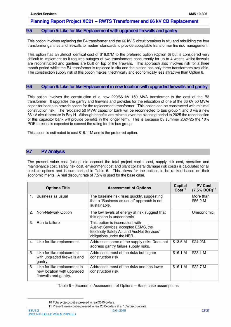
This option involves replacing the B4 transformer and the 66 kV S circuit breakers in situ and rebuilding the four transformer gantries and firewalls to modern standards to provide acceptable transformer fire risk management. This option has an almost identical cost of $16.07M to the preferred option (Option 6) but is considered very difficult to implement as it requires outages of two transformers concurrently for up to 4 weeks whilst firewalls are reconstructed and gantries are built on top of the firewalls. This approach also involves risk for a three month period whilst the B4 transformer is replaced in situ and the station has only three transformers available. The construction supply risk of this option makes it technically and economically less attractive than Option 6.
9.6 Option 6: Like for like Replacement in new location with upgraded firewalls and gantry
This option involves the construction of a new 220/66 kV 150 MVA transformer to the east of the B3 transformer. It upgrades the gantry and firewalls and provides for the relocation of one of the 66 kV 50 MVAr capacitor banks to provide space for the replacement transformer. This option can be constructed with minimal construction risk. The relocated 50 MVAr capacitor bank will be reconnected to bus group 1 and 3 via a new 66 kV circuit breaker in Bay H. Although benefits are minimal over the planning period to 2025 the reconnection of this capacitor bank will provide benefits in the longer term. This is because by summer 2024/25 the 10% POE forecast is expected to exceed the rating for this bus group. This option is estimated to cost $16.11M and is the preferred option.
9.7 PV Analysis
The present value cost (taking into account the total project capital cost, supply risk cost, operation and maintenance cost, safety risk cost, environment cost and plant collateral damage risk costs) is calculated for all credible options and is summarised in Table 6. This allows for the options to be ranked based on their economic merits. A real discount rate of 7.5% is used for the base case.
Options Title Assessment of Options Capital Cost
10
PV Cost (7.5% DCR)
11
1. Business as usual The baseline risk rises quickly, suggesting that a “Business as usual” approach is not sustainable.
More than $56.2 M
2. Non-Network Option The low levels of energy at risk suggest that this option is uneconomic.
Uneconomic
3. Run to failure This option is inconsistent with AusNet Services’ accepted ESMS, the Electricity Safety Act and AusNet Services’ obligations under the NER.
4. Like for like replacement. Addresses some of the supply risks Does not address gantry failure supply risks.
$13.5 M $24.2M.
5. Like for like replacement with upgraded firewalls and gantry.
Addresses most of the risks but higher construction risk.
$16.1 M $23.1 M
6. Like for like replacement in new location with upgraded firewalls and gantry.
Addresses most of the risks and has lower construction risk.
$16.1 M $22.7 M
Table 6 – Economic Assessment of Options – Base case assumptions
10 Total project cost expressed in real 2015 dollars.
11 Present value cost expressed in real 2015 dollars at a 7.5% discount rate.
AusNet Services AMS 10-306
Planning Report Project XC21 – RWTS Transformer and 66 kV CB Replacement
ISSUE 2 15/04/2015 23/ 27 UNCONTROLLED WHEN PRINTED
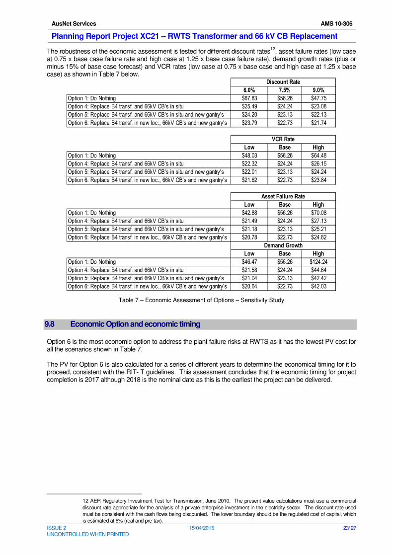
The robustness of the economic assessment is tested for different discount rates12
, asset failure rates (low case at 0.75 x base case failure rate and high case at 1.25 x base case failure rate), demand growth rates (plus or minus 15% of base case forecast) and VCR rates (low case at 0.75 x base case and high case at 1.25 x base case) as shown in Table 7 below.
Table 7 – Economic Assessment of Options – Sensitivity Study
9.8 Economic Option and economic timing
Option 6 is the most economic option to address the plant failure risks at RWTS as it has the lowest PV cost for all the scenarios shown in Table 7. The PV for Option 6 is also calculated for a series of different years to determine the economical timing for it to proceed, consistent with the RIT- T guidelines. This assessment concludes that the economic timing for project completion is 2017 although 2018 is the nominal date as this is the earliest the project can be delivered.
12 AER Regulatory Investment Test for Transmission, June 2010. The present value calculations must use a commercial
discount rate appropriate for the analysis of a private enterprise investment in the electricity sector. The discount rate used
must be consistent with the cash flows being discounted. The lower boundary should be the regulated cost of capital, which
is estimated at 6% (real and pre-tax).
6.0% 7.5% 9.0%
Option 1: Do Nothing $67.83 $56.26 $47.75
Option 4: Replace B4 transf. and 66kV CB's in situ $25.49 $24.24 $23.08
Option 5: Replace B4 transf. and 66kV CB's in situ and new gantry's $24.20 $23.13 $22.13
Option 6: Replace B4 transf. in new loc., 66kV CB's and new gantry's $23.79 $22.73 $21.74
Low Base High
Option 1: Do Nothing $48.03 $56.26 $64.48
Option 4: Replace B4 transf. and 66kV CB's in situ $22.32 $24.24 $26.15
Option 5: Replace B4 transf. and 66kV CB's in situ and new gantry's $22.01 $23.13 $24.24
Option 6: Replace B4 transf. in new loc., 66kV CB's and new gantry's $21.62 $22.73 $23.84
Low Base High
Option 1: Do Nothing $42.88 $56.26 $70.08
Option 4: Replace B4 transf. and 66kV CB's in situ $21.49 $24.24 $27.13
Option 5: Replace B4 transf. and 66kV CB's in situ and new gantry's $21.18 $23.13 $25.21
Option 6: Replace B4 transf. in new loc., 66kV CB's and new gantry's $20.78 $22.73 $24.82
Low Base High
Option 1: Do Nothing $46.47 $56.26 $124.24
Option 4: Replace B4 transf. and 66kV CB's in situ $21.58 $24.24 $44.64
Option 5: Replace B4 transf. and 66kV CB's in situ and new gantry's $21.04 $23.13 $42.42
Option 6: Replace B4 transf. in new loc., 66kV CB's and new gantry's $20.64 $22.73 $42.03
Demand Growth
Discount Rate
VCR Rate
Asset Failure Rate
AusNet Services AMS 10-306
Planning Report Project XC21 – RWTS Transformer and 66 kV CB Replacement
ISSUE 2 15/04/2015 24/ 27 UNCONTROLLED WHEN PRINTED
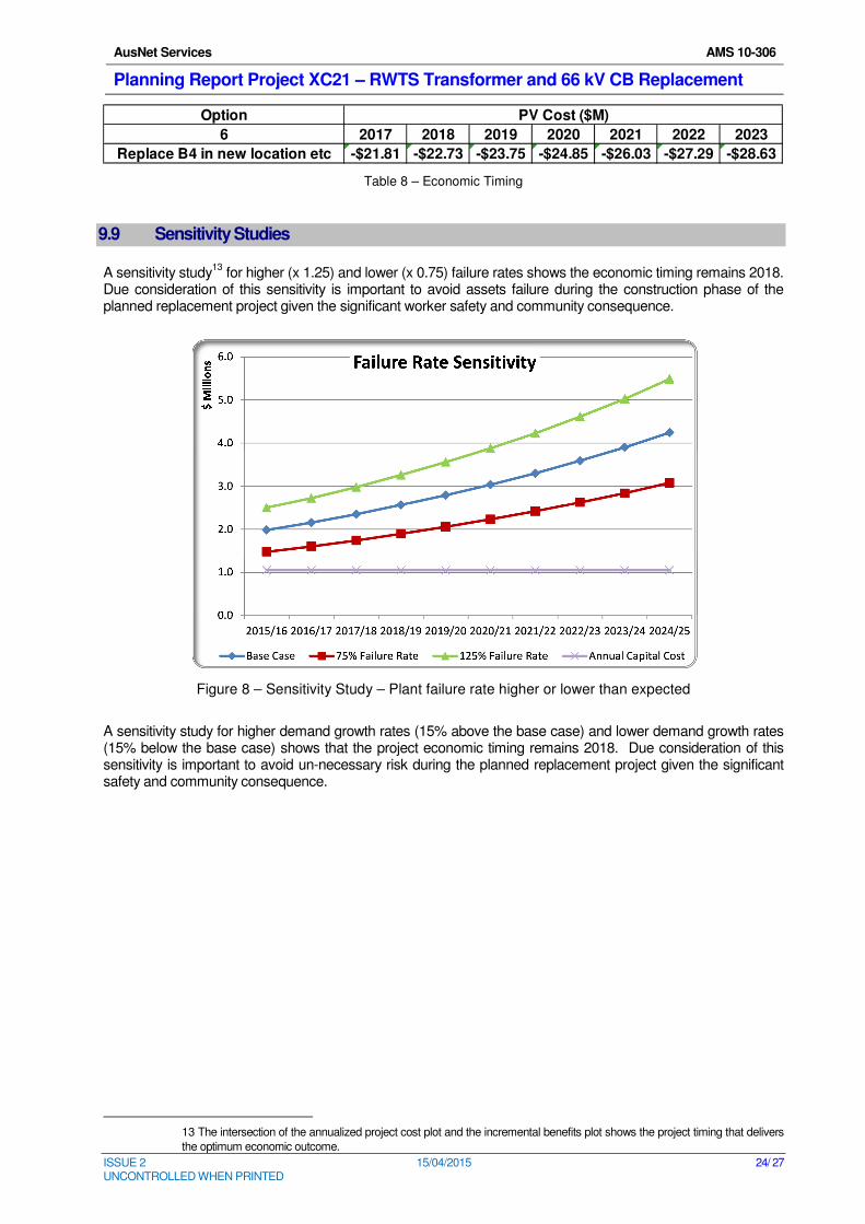
Table 8 – Economic Timing
9.9 Sensitivity Studies
A sensitivity study13
for higher (x 1.25) and lower (x 0.75) failure rates shows the economic timing remains 2018. Due consideration of this sensitivity is important to avoid assets failure during the construction phase of the planned replacement project given the significant worker safety and community consequence.
Figure 8 – Sensitivity Study – Plant failure rate higher or lower than expected
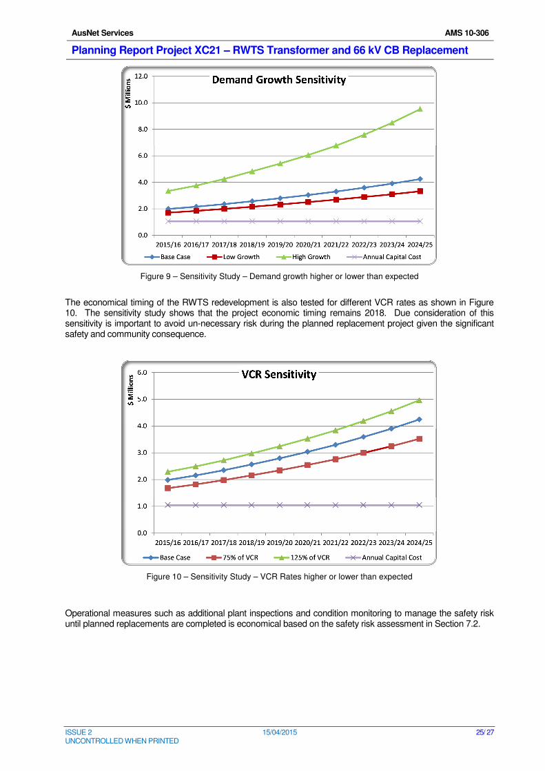
A sensitivity study for higher demand growth rates (15% above the base case) and lower demand growth rates (15% below the base case) shows that the project economic timing remains 2018. Due consideration of this sensitivity is important to avoid un-necessary risk during the planned replacement project given the significant safety and community consequence.
13 The intersection of the annualized project cost plot and the incremental benefits plot shows the project timing that delivers
the optimum economic outcome.
Option PV Cost ($M)
6 2017 2018 2019 2020 2021 2022 2023
Replace B4 in new location etc -$21.81 -$22.73 -$23.75 -$24.85 -$26.03 -$27.29 -$28.63
AusNet Services AMS 10-306
Planning Report Project XC21 – RWTS Transformer and 66 kV CB Replacement
ISSUE 2 15/04/2015 25/ 27 UNCONTROLLED WHEN PRINTED
Figure 9 – Sensitivity Study – Demand growth higher or lower than expected
The economical timing of the RWTS redevelopment is also tested for different VCR rates as shown in Figure 10. The sensitivity study shows that the project economic timing remains 2018. Due consideration of this sensitivity is important to avoid un-necessary risk during the planned replacement project given the significant safety and community consequence.
Figure 10 – Sensitivity Study – VCR Rates higher or lower than expected
Operational measures such as additional plant inspections and condition monitoring to manage the safety risk until planned replacements are completed is economical based on the safety risk assessment in Section 7.2.
AusNet Services AMS 10-306
Planning Report Project XC21 – RWTS Transformer and 66 kV CB Replacement
ISSUE 2 15/04/2015 26/ 27 UNCONTROLLED WHEN PRINTED
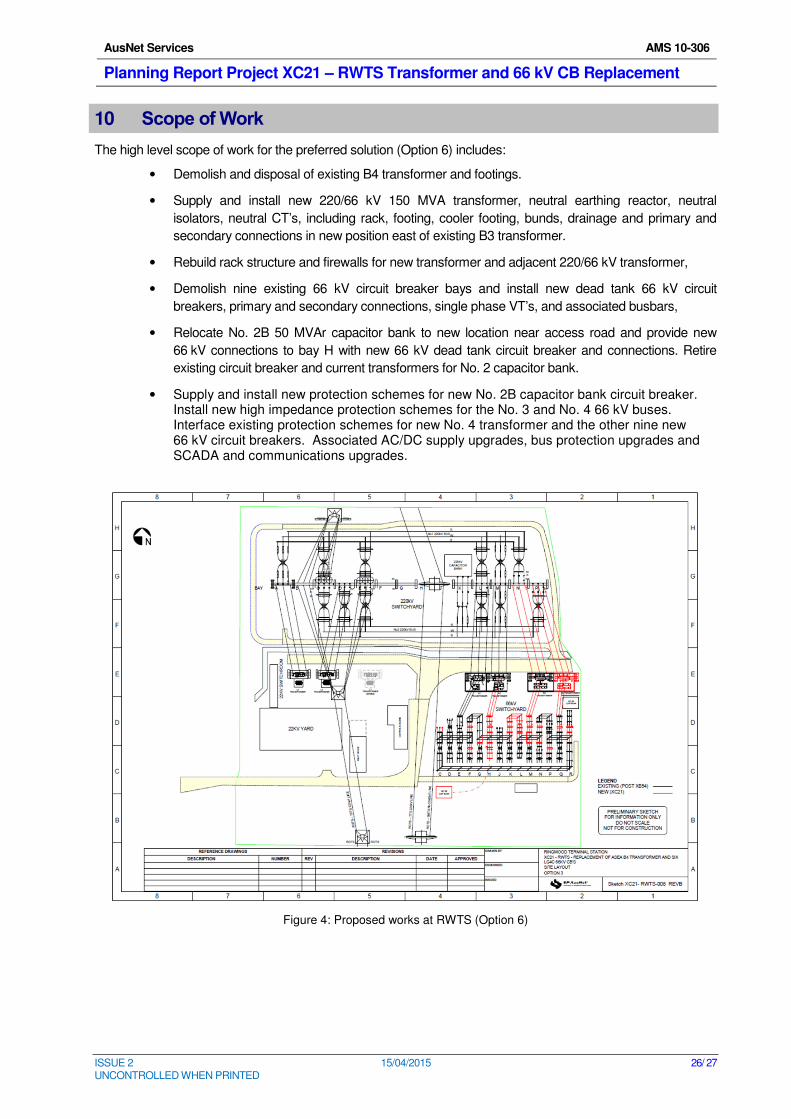
10 Scope of Work
The high level scope of work for the preferred solution (Option 6) includes:
• Demolish and disposal of existing B4 transformer and footings.
• Supply and install new 220/66 kV 150 MVA transformer, neutral earthing reactor, neutral
isolators, neutral CT’s, including rack, footing, cooler footing, bunds, drainage and primary and
secondary connections in new position east of existing B3 transformer.
• Rebuild rack structure and firewalls for new transformer and adjacent 220/66 kV transformer,
• Demolish nine existing 66 kV circuit breaker bays and install new dead tank 66 kV circuit
breakers, primary and secondary connections, single phase VT’s, and associated busbars,
• Relocate No. 2B 50 MVAr capacitor bank to new location near access road and provide new
66 kV connections to bay H with new 66 kV dead tank circuit breaker and connections. Retire
existing circuit breaker and current transformers for No. 2 capacitor bank.
• Supply and install new protection schemes for new No. 2B capacitor bank circuit breaker. Install new high impedance protection schemes for the No. 3 and No. 4 66 kV buses. Interface existing protection schemes for new No. 4 transformer and the other nine new 66 kV circuit breakers. Associated AC/DC supply upgrades, bus protection upgrades and SCADA and communications upgrades.
Figure 4: Proposed works at RWTS (Option 6)
AusNet Services AMS 10-306
Planning Report Project XC21 – RWTS Transformer and 66 kV CB Replacement
ISSUE 2 15/04/2015 27/ 27 UNCONTROLLED WHEN PRINTED
APPENDIX A: PLANNING ESTIMATE FOR PREFERRED OPTION – OPTION 6 –
REPLACE B4 IN NEW LOCATION
[C-I-C]