Embed Size (px)
Citation preview
JACE, Niagara Niagara AX and the Sedona are of Inc.
AUR-AX-2 (JACE 2) Mounting and Wiring Guide 1 Rev 1 Published: July 1, 2011
304 N. Isabella Street
PO BOX 5189
Sylvester, GA 31791 USA
MOUNTING AND WIRING GUIDE
:
This document covers the mounting and wiring of the Aurora-AX series
(JACE 2) controller. It assumes that you are an engineer, technician, or
service person who is performing control system installation. Instructions
in this document apply to the following products:
Models Description
AUR-AX-2 AUR-AX-2 base unit controller, powered by (either):
NPB-PWR 24Vac/dc input/15Vdc output power module, DIN mountable
NPB-PWR-UN 90–263Vac universal input/15Vdc output power module, DIN mountable
WPB-XXX Wall-mount universal AC power adapter, with different models available,
where -XXX is either: -US, -EUR, or -UK (vary by AC wall plug).
Note Not covered in this document is the NiagaraAX software installation and configuration required for a
fully functioning unit. This includes setting host IP address and password, serial port configuration, and
other parameters. Refer to the JACE NiagaraAX Install and Startup Guide for this information.
In addition, the mounting and wiring of JACE® expansion options are covered in separate documents.
See sections ―Related Documentation,‖ page 4, and ―About Expansion Options,‖ page 8.
These are the main topics included in this document:
• Preparation, page 2
• Precautions, page 3
• Mounting, page 5
• Board Layout, page 7
• About Expansion Options, page 8
• Wiring Details, page 11
– Grounding, page 11
– Power Wiring, page 11
– Communications Wiring, page 15
• Power Up and Initial Checkout, page 17
• Using Status LEDs, page 19
• Maintaining the AUR-AX-2, page 20
• Replacement Parts, page 21
• Certifications, page 24
• Tab Mounting Dimensions, page 26
AURORA-AX-2 (JACE 200)

AUR-AX-2 (JACE 2) Mounting and Wiring Guide
Part Number 11842 Rev 1
2 Published: July 1, 2011
Included in this Package
Preparation
Preparation
Unpack the AUR-AX-2 and power module (NPB-PWR, NPB-PWR-UN, or WPM-XXX) and inspect the
package contents for damaged or missing components. If damaged, notify the appropriate carrier at once and
return any damaged components for immediate repair or replacement. See ―Returning a Defective Unit‖ on
page 23.
• Included in this Package
• Material and Tools Required
Included in this Package
Included in this package you should find the following items:
• a AUR-AX-2 or AUR-AX-2-USA base controller.
• This AUR-AX-2 (JACE 2) Mounting and Wiring Guide, Rev 1
• a hardware bag containing the following items:
– A grounding wire, with quick-disconnect 0.187‖ female connector.
• a power module (if ordered), which is required for operation.
The power module can be one of the following:
– NPB-PWR: 24Vac in-line, DIN-mount capable, with grounding wire, or
– NPB-PWR-UN: 90-263 Vac in-line, DIN-mount capable, with grounding wire, or
– WPM-XXX: External wall-mount power adapter (input: 90–254Vac, 50–60 Hz, output: 15Vdc, 1A)
where XXX varies by the AC wall plug (for installation locale), such as:
WPM-US (U.S. or Japan installations), WPM-EUR (European installations, type ―C‖ plug)
WPM-UK (United Kingdom installations, type ―B‖ plug)
Material and Tools Required
The following supplies and tools may be required for installation:
• DIN rail, type NS35/7.5 (35mm x 7.5mm) and DIN rail end-clips (stop clips), recommended for any
installation that includes NPB-PWR or NPB-PWR-UN module and/or optional I/O modules.
Note Length of DIN rail is determined by the number of optional DIN-mounted options.
See Figure 1 on page 6 for more details.
• If using a NPB-PWR power module, either one of the following:
– UL listed, Class 2, 24Vac transformer, rated at minimum of 8.5VA to 20VA (approximate range of
JACE-2 alone, to fully-expanded unit with four additional AUR-IO-16 modules and other option
boards). Note that a dedicated transformer is required (cannot also power additional equipment).
– 24Vdc power supply, capable of supplying at least 1A (24W).
• Suitable screws and screwdriver for mounting DIN rail, or if DIN rail not used, for mounting bases of
AUR-AX-2 controller, NPB-PWR or NPB-PWR-UN module (if used), and any I/O modules (if used).
• #2 phillips screwdriver: used to install and remove optional communications modules.
• Small flat-blade screwdriver: used for mounting or removing the AUR-AX-2 from DIN rail, also for
making wiring connections to RS-485 connector, and optionally LON and I/O connectors.
AUR-AX-2 (JACE 2) Mounting and Wiring Guide 3
Part Number 11842 Rev 1 Published: July 1, 2011
Precautions
Safety Precautions
Precautions
This document uses the following warning and caution conventions:
Caution Cautions remind the reader to be careful. They alert readers to situations where there is a chance
that the reader might perform an action that cannot be undone, might receive unexpected results, or
might lose data. Cautions contain an explanation of why the action is potentially problematic.
Warning Warnings alert the reader to proceed with extreme care. They alert readers to situations where there
is a chance that the reader might do something that can result in personal injury or equipment
damage. Warnings contain an explanation of why the action is potentially dangerous.
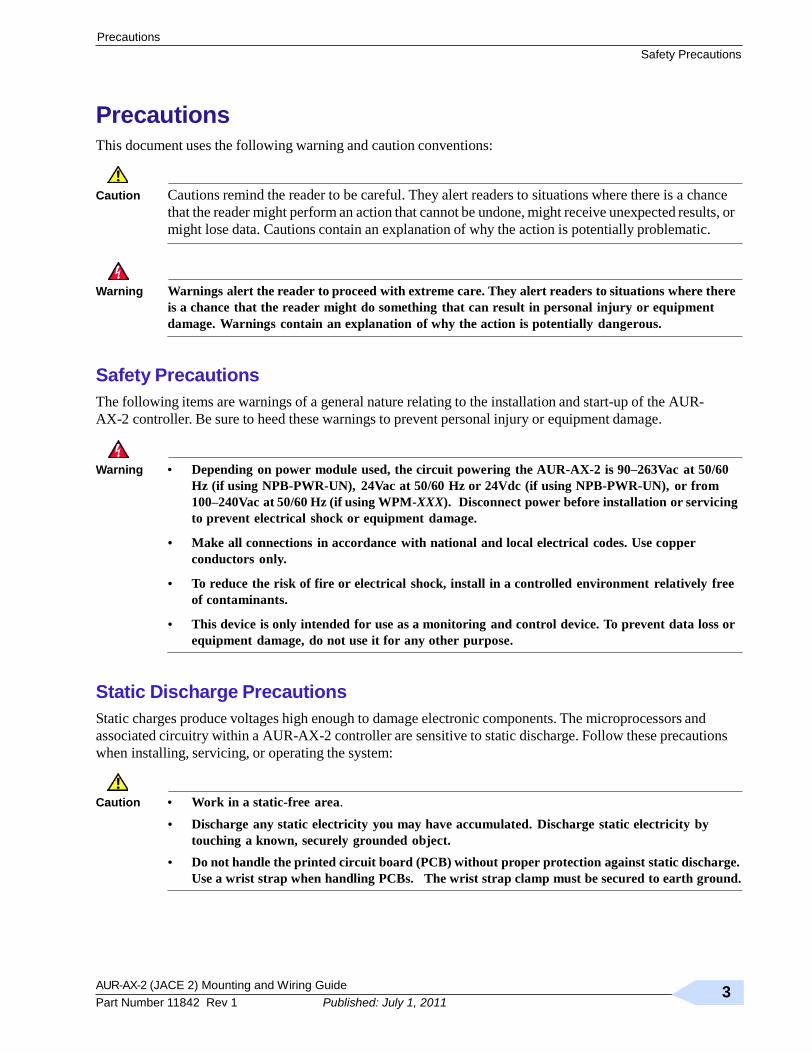
Safety Precautions
The following items are warnings of a general nature relating to the installation and start-up of the AUR-
AX-2 controller. Be sure to heed these warnings to prevent personal injury or equipment damage.
Warning • Depending on power module used, the circuit powering the AUR-AX-2 is 90–263Vac at 50/60
Hz (if using NPB-PWR-UN), 24Vac at 50/60 Hz or 24Vdc (if using NPB-PWR-UN), or from
100–240Vac at 50/60 Hz (if using WPM-XXX). Disconnect power before installation or servicing
to prevent electrical shock or equipment damage.
• Make all connections in accordance with national and local electrical codes. Use copper
conductors only.
• To reduce the risk of fire or electrical shock, install in a controlled environment relatively free
of contaminants.
• This device is only intended for use as a monitoring and control device. To prevent data loss or
equipment damage, do not use it for any other purpose.
Static Discharge Precautions
Static charges produce voltages high enough to damage electronic components. The microprocessors and
associated circuitry within a AUR-AX-2 controller are sensitive to static discharge. Follow these precautions
when installing, servicing, or operating the system:
Caution • Work in a static-free area.
• Discharge any static electricity you may have accumulated. Discharge static electricity by
touching a known, securely grounded object.
• Do not handle the printed circuit board (PCB) without proper protection against static discharge.
Use a wrist strap when handling PCBs. The wrist strap clamp must be secured to earth ground.

AUR-AX-2 (JACE 2) Mounting and Wiring Guide
Rev 1 4
Published: July 1, 2011
Battery Precautions
Related Documentation
Battery Precautions
Caution • The NiMH battery used in this device may present a risk of fire or chemical burn if mistreated.
Do not disassemble, heat above 122ºF (50ºC), or incinerate. Replace battery pack with type
NPB-BATT only. Use of another battery may present a risk of fire or explosion.
• Dispose of used battery promptly. Keep away from children. Do not disassemble and do not
dispose of in fire.
WEEE (Waste of Electrical and Electronic Equipment)
Recycling of Electronic Products: (International Installations)
In 2006 the European Union adopted regulations (WEEE) for the collection and recycling of all waste electrical
and electronic equipment. It is no longer allowable to simply throw away such equipment. Instead, these products
must enter the recycling process. To properly dispose of this product, please take it to a local recycling center.
If a local recycling center cannot be found, please return it to one of these offices:
Tridium Europe Ltd
1, The Grainstore Brooks
Green Road Coolham, West
Sussex RH138GR United
Kingdom
Tridium Asia Pacific Pte Ltd
17 Changi Business Park Central 1
Honeywell Building
Singapore 486073
Tridium Inc.
2256 Dabney Road, Suite C
Richmond, VA 23230
Related Documentation
For more details on configuring and using the AUR-AX-2 (JACE 2) controller, consult the following
documents:
• JACE NiagaraAX Install and Startup Guide
• AUR-IO-16 Installation and Configuration Guide
• AUR-IO-34 Installation and Configuration Guide
• Various option card installation documents, such as:
– NPB-LON Option Install Sheet
– NPB-2X-485 Option Install Sheet
– NPB-232 Option Install Sheet
See the ―About Option Cards‖ section on page 8 for a listing of option card types.
• NiagaraAX Ndio Guide
• NiagaraAX User Guide
AUR-AX-2 (JACE 2) Mounting and Wiring Guide 5
Part Number 11842 Rev 1 Published: July 1, 2011
Mounting
Environmental Requirements
Mounting
Mount the AUR-AX-2 controller in a location that allows clearance for wiring, servicing, and module removal.
Environmental Requirements
Note the following requirements for the controller’s mounting location:
• This product is intended for indoor use only. Do not expose the unit to ambient conditions outside of the
range of 0ºC (32º F) to 50ºC (122º F) and relative humidity outside the range 5% to 95% non-condensing
(pollution degree 1).
• If mounting inside an enclosure, that enclosure should be designed to keep the unit within its required
operating range considering a 20-watt dissipation by the controller, plus dissipation from any other
devices installed in the same enclosure. This is especially important if the controller is mounted inside an
enclosure with other heat producing equipment.
• Do not mount the unit:
– in an area where excessive moisture, corrosive fumes, or explosive vapors are present.
– where vibration or shock is likely to occur.
– in a location subject to electrical noise. This includes the proximity of large electrical contractors,
electrical machinery, welding equipment, and spark igniters, and variable frequency drives.
Physical Mounting
The following information applies about physically mounting the unit.
• You can mount the AUR-AX-2 in any orientation. It it not necessary to remove the cover before mounting.
• Mounting on a 35mm wide DIN rail is recommended. The controller’s base has a molded DIN rail slot
and locking clip, as do power modules (NPB-PWR, NPB-PWR-UN) and both types of I/O expansion
modules. Mounting on a DIN rail ensures accurate alignment of connectors between all modules.
• If DIN rail mounting is impractical, you can use screws in mounting tabs on the AUR-AX-2, then
in any end-connected accessory (NPB-PWR, etc.). Tab dimensions are on the last page of this
document.
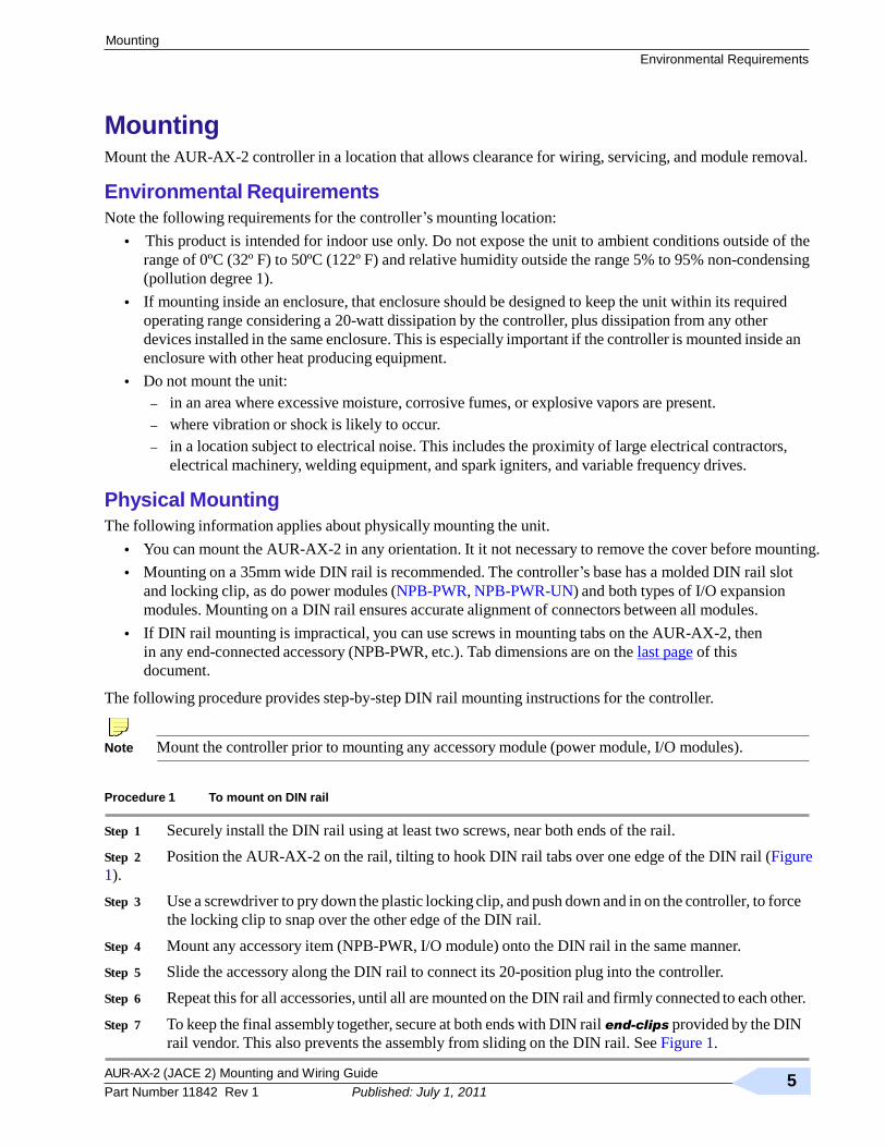
The following procedure provides step-by-step DIN rail mounting instructions for the controller.
Note Mount the controller prior to mounting any accessory module (power module, I/O modules).
Procedure 1 To mount on DIN rail
Step 1 Securely install the DIN rail using at least two screws, near both ends of the rail.
Step 2 Position the AUR-AX-2 on the rail, tilting to hook DIN rail tabs over one edge of the DIN rail (Figure
1).
Step 3 Use a screwdriver to pry down the plastic locking clip, and push down and in on the controller, to force
the locking clip to snap over the other edge of the DIN rail.
Step 4 Mount any accessory item (NPB-PWR, I/O module) onto the DIN rail in the same manner.
Step 5 Slide the accessory along the DIN rail to connect its 20-position plug into the controller.
Step 6 Repeat this for all accessories, until all are mounted on the DIN rail and firmly connected to each other.
Step 7 To keep the final assembly together, secure at both ends with DIN rail end-clips provided by the DIN
rail vendor. This also prevents the assembly from sliding on the DIN rail. See Figure 1.
AUR-AX-2 (JACE 2) Mounting and Wiring Guide
Rev 1 6
Published: July 1, 2011
Removing and Replacing the Cover
Mounting
Figure 1 AUR-AX-2 controller and accessory mounting details.
Mounting on DIN Rail
Removing from DIN Rail
DIN rail
End Clip NPB-PWR or NPB-PWR-UN
AUR-AX-2
Install DIN rail End Clip DIN Rail (Stop Clip) at both ends of End Clip final assembly.
AUR-AX-2
AUR-IO-16
Up to four (4) AUR-IO-16
modules
7.13‖ (181 mm) are supported.
6.38‖ (162 mm)
NPB-PWR or
2.05‖ (52 mm) AUR-IO-16 AUR-IO-16 AUR-IO-16 AUR-IO-16 NPB-PWR-UN
AUR-AX-2
4.1‖ (104 mm)
NOTE: If installing
10.35‖ (263 mm) AUR-IO-16 modules and
13.58‖ (345 mm) using the NPB-PWR or NPB-PWR-UN power
16.81‖ (427 mm) supply module, the power supply module installs at
20.04‖ (509 mm) the end of the chain.
23.27‖ (591 mm)
Removing and Replacing the Cover
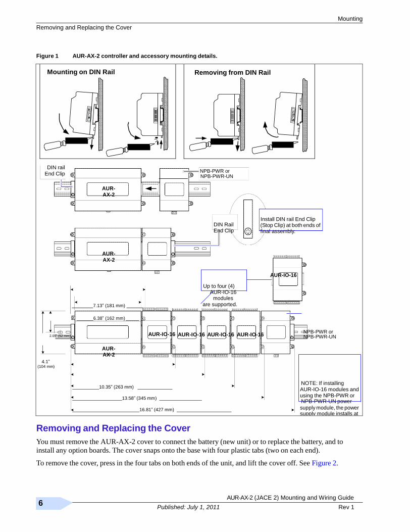
You must remove the AUR-AX-2 cover to connect the battery (new unit) or to replace the battery, and to
install any option boards. The cover snaps onto the base with four plastic tabs (two on each end).
To remove the cover, press in the four tabs on both ends of the unit, and lift the cover off. See Figure 2.
AUR-AX-2 (JACE 2) Mounting and Wiring Guide 7
Part Number 11842 Rev 1 Published: July 1, 2011
Board Layout
Removing and Replacing the Cover
Figure 2 Press in four tabs on ends of cover to remove cover.
Cover Tabs (2 each end)
Cover lifted away
Press Tabs In
Note If accessory modules are plugged into the controller, you may need to slide them away from the unit to
get to the cover tabs.
To replace the cover, orient it so the cutout area for comm ports is correct, then push inwards to snap in place.
Board Layout
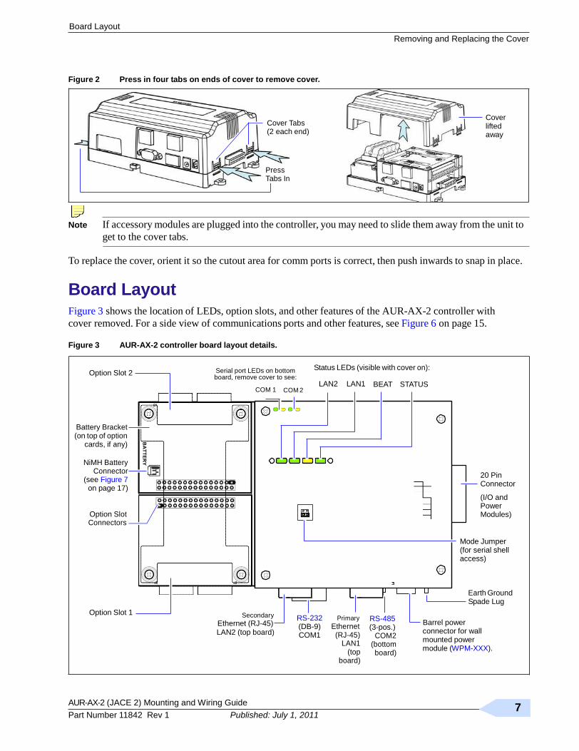
Figure 3 shows the location of LEDs, option slots, and other features of the AUR-AX-2 controller with
cover removed. For a side view of communications ports and other features, see Figure 6 on page 15.
Figure 3 AUR-AX-2 controller board layout details.
Option Slot 2
Serial port LEDs on bottom board, remove cover to see:
COM 1 COM 2
Status LEDs (visible with cover on):
LAN2 LAN1 BEAT STATUS
Battery Bracket (on top of option
cards, if any)
NiMH Battery Connector
(see Figure 7 on page 17)
Option Slot Connectors
20 Pin Connector
(I/O and Power Modules)
Mode Jumper (for serial shell access)
Option Slot 1
Secondary
Ethernet (RJ-45)
RS-232 (DB-9)
Primary
Ethernet
RS-485 (3-pos.)
Barrel power
Earth Ground Spade Lug
LAN2 (top board) COM1 (RJ-45) LAN1
(top board)
COM2 (bottom board)
connector for wall mounted power module (WPM-XXX).
AUR-AX-2 (JACE 2) Mounting and Wiring Guide
Rev 1 8
Published: July 1, 2011
About Option Cards
About Expansion Options
About Expansion Options
The AUR-AX-2 controller provides for field-installable expansion with two kinds of options:
• Option cards—Install on connectors inside the controller base unit. See ―About Option Cards‖.
• Accessory modules—To ―chain‖ on the AUR-AX-2’s 20-pin end connector. See ―About Accessory
Modules‖.
About Option Cards
The AUR-AX-2 has two (2) option slots for custom option cards designed for use with JACE controllers. Each
slot has a 30-pin connector on the controller’s base board. See Figure 3 on page 7.
Warning Power to the controller must be OFF when installing or removing option cards, or damage will occur!
Also, you must be very careful to plug an option card into its connector properly (pins aligned).
Option cards typically provide additional communications features, such as with the following available models
(with others still in development) listed in Table 1.
Table 1 AUR-AX-2 option cards.
Model Description Notes
NPB-LON FTT-10A LON (LonWorks) adapter
with a 2-position removable
screw-terminal connector plug.
Up to 2 LON option cards may be installed.
• If one LON option, it operates as LON1, regardless of slot.
• If two LON options, LON1 is Option slot 1, LON2 is Option slot 2.
NPB-2X-485 Dual, optically-isolated, RS-485
adapter with two 3-position
removable screw-terminal
connector plugs.
One or two 485 option cards may be installed.
If installed in Option slot 1, ports are COM3 and COM4. If two 485 options
are installed, ports are COM3 and COM4 for Option slot 1, and COM5 and
COM6 for Option slot 2.
NPB-MDM 56Kbps Auto-dial/Auto-answer
Modem with one RJ-11 connector
for phone line.
Maximum of one. Does not have own UART (unlike NPB-2X-485,
NPB-232, etc.). Must be installed in Option slot 1, where it operates as
COM1. This disables the RS-232 base serial port (DB-9 connector) on the
AUR-AX-2 during normal operation. Note: Not supported if NPB-GPRS
modem option is also installed. Note: If a NPB-MDM is installed, and the ―mode jumper‖ (see Figure 3) is
put in ―Serial Shell‖ position, the AUR-AX-2 base RS-232 port becomes
active immediately following a reboot. This allows an RS-232 connection
to the ―serial shell‖ for debugging purposes. To re-enable the modem, you
must put the mode jumper back in the ―Normal‖ position, and reboot
again.
NPB-232 Single port RS-232 adapter, with a
DB-9M connector. Uses its own
on-board UART. Supports baud
rates up to 115200.
One or two 232 option cards may be installed.
If installed in Option slot 1, port is COM3. If two 232 options are installed,
ports are COM3 for Option slot 1, and COM4 for Option slot 2
NPB-GPRS-W
NPB-GPRS
Wireless GSM cellular modem
using GPRS (General Packet
Radio Service) data technology,
powered by the controller.
Requires AX-3.4 or later. One GPRS option card is supported.
Includes SMA coax stub antenna.
The NPB-GPRS-W model is bundled with a Wyless provisioned SIM card.
The NPB-GPRS model does not include a SIM card.
NPB-SED-001 Sedona Framework™ option card
with Jennic JN5139 microcontroller
and Sedona module for 802.15.4
wireless network and 6LoWPAN
bridge support. Wired RS-485
MSTP networking also supported.
Requires AX-3.4 or later. One Sedona option card is supported.
Includes RP-SMA coax stub antenna. If installed in Option slot 1, is COM3.
For more details on port assignments and other features, refer to specific option card installation documents.

AUR-AX-2 (JACE 2) Mounting and Wiring Guide 9
Part Number 11842 Rev 1 Published: July 1, 2011
About Expansion Options
About Option Cards
Mounting Option Cards
Refer to the installation document that accompanies a specific option card for complete details. The following
procedure provides a basic set of steps.
Procedure 2 Mounting option cards on a AUR-AX-2 controller.
Step 1 Remove power from the controller—see the previous Warning.
Step 2 Remove the cover. See ―Removing and Replacing the Cover,‖ page 6.
Step 3 Remove the battery and bracket assembly by taking out the four screws holding it in place, setting the
screws aside for later. Unplug the battery from the connector on the controller’s base board.
Step 4 Remove the blanking end plate for the slot you are installing the option card into.
(Retain the blanking plate in case the option card must be removed at a later date.)
Step 5 Carefully insert the pins of the option card into the socket of the appropriate option card slot.
The mounting holes on the option board should line up with the standoffs on the base board. If they
do not, the connector is not properly aligned. Press until the option card is completely seated.
Step 6 Place the custom end plate that came with the option card over the connector(s) of the option card.
Step 7 Plug the battery connector plug into the battery connector on the controller’s base board.
Step 8 Set the battery and bracket assembly back over the option card slots, with the mounting holes aligned
with the standoffs.
Step 9 Place the four screws through the battery bracket, end plates, and into the standoffs on the controller’s
base board. Using a screwdriver, hand tighten these screws.
Step 10 Replace the cover.
AUR-AX-2 (JACE 2) Mounting and Wiring Guide
Rev 1 10
Published: July 1, 2011
About Accessory Modules
About Expansion Options
About Accessory Modules
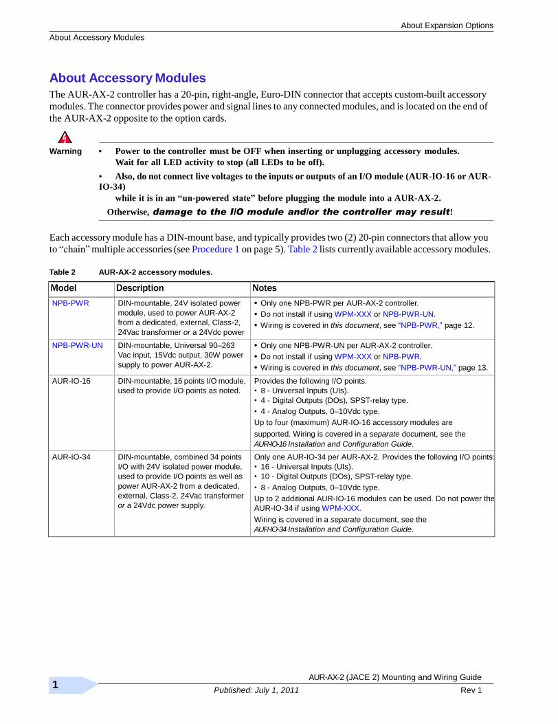
The AUR-AX-2 controller has a 20-pin, right-angle, Euro-DIN connector that accepts custom-built accessory
modules. The connector provides power and signal lines to any connected modules, and is located on the end of
the AUR-AX-2 opposite to the option cards.
Warning • Power to the controller must be OFF when inserting or unplugging accessory modules.
Wait for all LED activity to stop (all LEDs to be off).
• Also, do not connect live voltages to the inputs or outputs of an I/O module (AUR-IO-16 or AUR-
IO-34)
while it is in an “un-powered state” before plugging the module into a AUR-AX-2.
Otherwise, damage to the I/O module and/or the controller may result!
Each accessory module has a DIN-mount base, and typically provides two (2) 20-pin connectors that allow you
to ―chain‖ multiple accessories (see Procedure 1 on page 5). Table 2 lists currently available accessory modules.
Table 2 AUR-AX-2 accessory modules.
Model Description Notes
NPB-PWR DIN-mountable, 24V isolated power
module, used to power AUR-AX-2
from a dedicated, external, Class-2,
24Vac transformer or a 24Vdc power
supply.
• Only one NPB-PWR per AUR-AX-2 controller.
• Do not install if using WPM-XXX or NPB-PWR-UN.
• Wiring is covered in this document, see ―NPB-PWR,‖ page 12.
NPB-PWR-UN DIN-mountable, Universal 90–263
Vac input, 15Vdc output, 30W power
supply to power AUR-AX-2.
• Only one NPB-PWR-UN per AUR-AX-2 controller.
• Do not install if using WPM-XXX or NPB-PWR.
• Wiring is covered in this document, see ―NPB-PWR-UN,‖ page 13.
AUR-IO-16 DIN-mountable, 16 points I/O module,
used to provide I/O points as noted.
Provides the following I/O points:
• 8 - Universal Inputs (UIs).
• 4 - Digital Outputs (DOs), SPST-relay type.
• 4 - Analog Outputs, 0–10Vdc type.
Up to four (maximum) AUR-IO-16 accessory modules are
supported. Wiring is covered in a separate document, see the
AUR-IO-16 Installation and Configuration Guide.
AUR-IO-34 DIN-mountable, combined 34 points
I/O with 24V isolated power module,
used to provide I/O points as well as
power AUR-AX-2 from a dedicated,
external, Class-2, 24Vac transformer
or a 24Vdc power supply.
Only one AUR-IO-34 per AUR-AX-2. Provides the following I/O points:
• 16 - Universal Inputs (UIs).
• 10 - Digital Outputs (DOs), SPST-relay type.
• 8 - Analog Outputs, 0–10Vdc type.
Up to 2 additional AUR-IO-16 modules can be used. Do not power the
AUR-IO-34 if using WPM-XXX.
Wiring is covered in a separate document, see the
AUR-IO-34 Installation and Configuration Guide.
AUR-AX-2 (JACE 2) Mounting and Wiring Guide 11
Part Number 11842 Rev 1 Published: July 1, 2011
Wiring Details
Grounding
Wiring Details
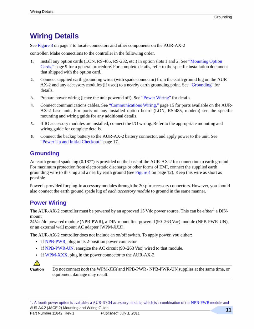
See Figure 3 on page 7 to locate connectors and other components on the AUR-AX-2
controller. Make connections to the controller in the following order.
1. Install any option cards (LON, RS-485, RS-232, etc.) in option slots 1 and 2. See ―Mounting Option
Cards,‖ page 9 for a general procedure. For complete details, refer to the specific installation document
that shipped with the option card.
2. Connect supplied earth grounding wires (with spade connector) from the earth ground lug on the AUR-
AX-2 and any accessory modules (if used) to a nearby earth grounding point. See ―Grounding‖ for
details.
3. Prepare power wiring (leave the unit powered off). See ―Power Wiring‖ for details.
4. Connect communications cables. See ―Communications Wiring,‖ page 15 for ports available on the AUR-
AX-2 base unit. For ports on any installed option board (LON, RS-485, modem) see the specific
mounting and wiring guide for any additional details.
5. If IO accessory modules are installed, connect the I/O wiring. Refer to the appropriate mounting and
wiring guide for complete details.
6. Connect the backup battery to the AUR-AX-2 battery connector, and apply power to the unit. See
―Power Up and Initial Checkout,‖ page 17.
Grounding
An earth ground spade lug (0.187") is provided on the base of the AUR-AX-2 for connection to earth ground.
For maximum protection from electrostatic discharge or other forms of EMI, connect the supplied earth
grounding wire to this lug and a nearby earth ground (see Figure 4 on page 12). Keep this wire as short as
possible.
Power is provided for plug-in accessory modules through the 20-pin accessory connectors. However, you should
also connect the earth ground spade lug of each accessory module to ground in the same manner.
Power Wiring
The AUR-AX-2 controller must be powered by an approved 15 Vdc power source. This can be either1 a DIN-
mount
24Vac/dc-powered module (NPB-PWR), a DIN-mount line-powered (90–263 Vac) module (NPB-PWR-UN),
or an external wall mount AC adapter (WPM-XXX).
The AUR-AX-2 controller does not include an on/off switch. To apply power, you either:
• if NPB-PWR, plug in its 2-position power connector.
• if NPB-PWR-UN, energize the AC circuit (90–263 Vac) wired to that module.
• if WPM-XXX, plug in the power connector to the AUR-AX-2.
Caution Do not connect both the WPM-XXX and NPB-PWR / NPB-PWR-UN supplies at the same time, or
equipment damage may result.
1. A fourth power option is available: a AUR-IO-34 accessory module, which is a combination of the NPB-PWR module and
AUR-AX-2 (JACE 2) Mounting and Wiring Guide
Rev 1 12
Published: July 1, 2011
two AUR-IO-16 modules (plus two extra relays). Please refer to its mounting and wiring instructions document for more details. For general information on accessory modules, see ―About Accessory Modules,‖ page 10.
AUR-AX-2 (JACE 2) Mounting and Wiring Guide 13
Part Number 11842 Rev 1 Published: July 1, 2011
Power Wiring
Wiring Details
If desired, you can use the wall mount WPM-XXX in your office (to initially commission the AUR-AX-2), and
then install the AUR-AX-2 at the job using either a NPB-PWR or NPB-PWR-UN module. The following
sections provide more details:
• NPB-PWR (24Vac/dc-powered in-line module)
• NPB-PWR-UN (Universal 90V–263Vac-powered in-line module)
• WPM-XXX (Wall Power Modules)
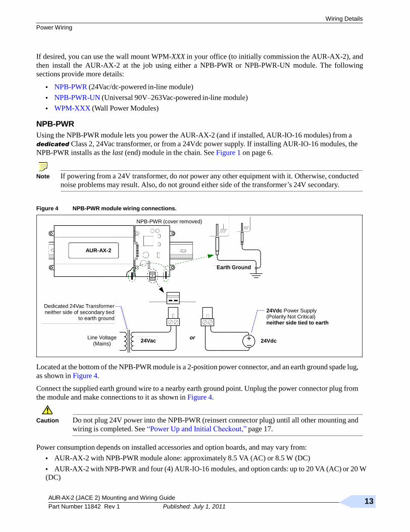
NPB-PWR
Using the NPB-PWR module lets you power the AUR-AX-2 (and if installed, AUR-IO-16 modules) from a
dedicated Class 2, 24Vac transformer, or from a 24Vdc power supply. If installing AUR-IO-16 modules, the
NPB-PWR installs as the last (end) module in the chain. See Figure 1 on page 6.
Note If powering from a 24V transformer, do not power any other equipment with it. Otherwise, conducted
noise problems may result. Also, do not ground either side of the transformer’s 24V secondary.
Figure 4 NPB-PWR module wiring connections.
NPB-PWR (cover removed)
AUR-AX-2
Earth Ground
Dedicated 24Vac Transformer neither side of secondary tied
to earth ground
Line Voltage (Mains)
24Vac or
24Vdc Power Supply (Polarity Not Critical) neither side tied to earth
+ 24Vdc
–
Located at the bottom of the NPB-PWR module is a 2-position power connector, and an earth ground spade lug,
as shown in Figure 4.
Connect the supplied earth ground wire to a nearby earth ground point. Unplug the power connector plug from
the module and make connections to it as shown in Figure 4.
Caution Do not plug 24V power into the NPB-PWR (reinsert connector plug) until all other mounting and
wiring is completed. See ―Power Up and Initial Checkout,‖ page 17.
Power consumption depends on installed accessories and option boards, and may vary from:
• AUR-AX-2 with NPB-PWR module alone: approximately 8.5 VA (AC) or 8.5 W (DC)
• AUR-AX-2 with NPB-PWR and four (4) AUR-IO-16 modules, and option cards: up to 20 VA (AC) or 20 W
(DC)

AUR-AX-2 (JACE 2) Mounting and Wiring Guide
Rev 1 14
Published: July 1, 2011
Wiring Details
Power Wiring
NPB-PWR-UN
The NPB-PWR-UN module lets you power the AUR-AX-2 (and if installed, AUR-IO-16 modules) from AC
line power, with a universal input range from 90–263Vac. If installing AUR-IO-16 modules, the NPB-PWR-
UN installs as the last (end) module in the chain. See Figure 1 on page 6.
Warning • A 120Vac or 240Vac circuit powers the NPB-PWR-UN. Disconnect power to this circuit
before installation to prevent electrical shock of equipment damage.
• Make all connections in accordance with national and local electrical codes. Use copper
conductors only.
• Do not exceed the 30W capacity of the NPB-PWR-UN by the powered devices.
Power input connections are made to the terminals on the circuit board (cover removal is required). An earth
ground connection must be made to the grounding lug using the supplied earth wire. See Figure 5.
Figure 5 NPB-PWR-UN module wiring connections.
Remove cover
JACE or last
AUR-IO-16
AC Input
6-pin connector not used
NOTE: The 6-pin connector of the NPB-PWR-UN is not used with a AUR-AX-2 series controller.
The 6-pin connector is designed for use with other controllers or modules, and must be left unused.
L N 120 or 240Vac
50–60 Hz Single Phase
Line
Neutral
Earth Ground
Procedure 3 Wiring NPB-PWR-UN input power and earth ground.
Step 1 Remove power from the AC circuit being wired to the NPB-PWR-UN—see previous Warning •.
Step 2 Remove the NPB-PWR-UN cover.
To do this, press in the four tabs on both ends of the unit, and lift the cover off.
Step 3 If the controller or a AUR-IO-16 accessory module is plugged into the unit, you may need to slide it
away to get to the cover tabs.
Step 4 Connect the supplied earth grounding wire to a nearby grounding point. See Figure 5.
Step 5 Make AC circuit connections line (mains) and neutral to the terminals labeled ―INPUT PWR.‖
Step 6 Replace the cover on the NPB-PWR-UN.
Make sure all modules in the mounted assembly are firmly connected together and secured.
Caution Do not energize the AC circuit wired to the NPB-PWR-UN until all other JACE mounting and
wiring is completed. See ―Power Up and Initial Checkout,‖ page 17.
AUR-AX-2 (JACE 2) Mounting and Wiring Guide 15
Part Number 11842 Rev 1 Published: July 1, 2011
Power Wiring
Wiring Details
WPM-XXX
All models of wall power modules (US, EUR, UK, JA) are self-contained, isolated, switching power supplies
designed to plug into a standard building power receptacle of appropriate voltage. To supply power to the AUR-
AX-2, you then simply plug the barrel connector plug from the WPM-XXX into the barrel power connector on
the
AUR-AX-2 base board (see Figure 6 on
page 15).
Caution Do not plug the barrel connector plug from the WPM-XXX into the AUR-AX-2 until all other
mounting and wiring is completed. See ―Power Up and Initial Checkout,‖ page 17.
AUR-AX-2 (JACE 2) Mounting and Wiring Guide
Rev 1 16
Published: July 1, 2011
Wiring Details
Communications Wiring
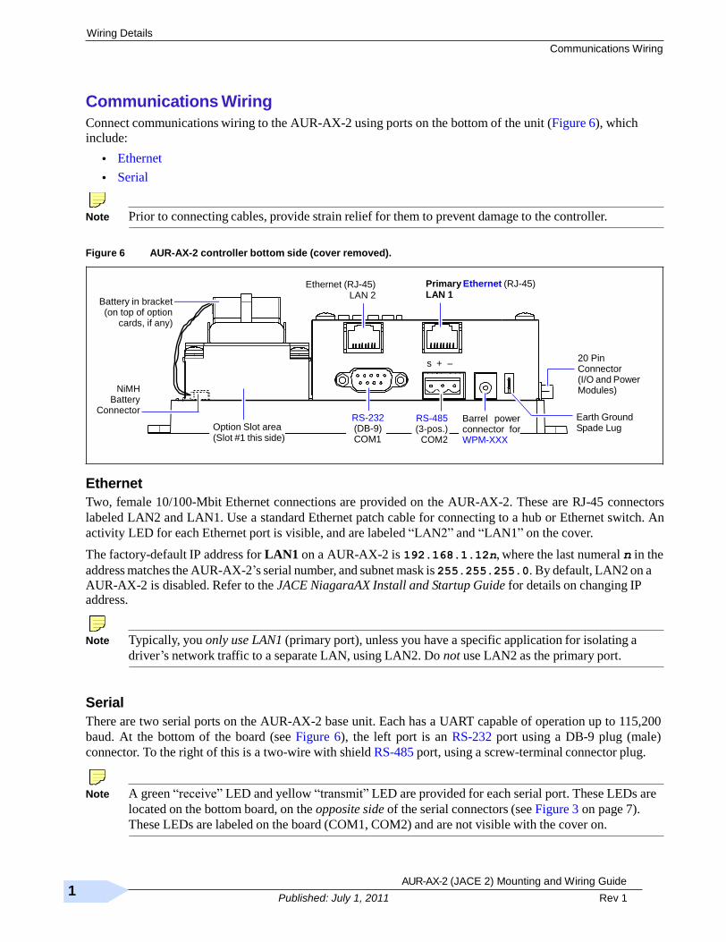
Communications Wiring
Connect communications wiring to the AUR-AX-2 using ports on the bottom of the unit (Figure 6), which
include:
• Ethernet
• Serial
Note Prior to connecting cables, provide strain relief for them to prevent damage to the controller.
Figure 6 AUR-AX-2 controller bottom side (cover removed).
Battery in bracket (on top of option
cards, if any)
Ethernet (RJ-45) LAN 2
Primary Ethernet (RJ-45) LAN 1
NiMH Battery
Connector
Option Slot area (Slot #1 this side)
RS-232 (DB-9) COM1
s + –
RS-485 (3-pos.)
COM2
Barrel power connector for WPM-XXX
20 Pin Connector (I/O and Power Modules)
Earth Ground Spade Lug
Ethernet
Two, female 10/100-Mbit Ethernet connections are provided on the AUR-AX-2. These are RJ-45 connectors
labeled LAN2 and LAN1. Use a standard Ethernet patch cable for connecting to a hub or Ethernet switch. An
activity LED for each Ethernet port is visible, and are labeled ―LAN2‖ and ―LAN1‖ on the cover.
The factory-default IP address for LAN1 on a AUR-AX-2 is 192.168.1.12n, where the last numeral n in the
address matches the AUR-AX-2’s serial number, and subnet mask is 255.255.255.0. By default, LAN2 on a AUR-AX-2 is disabled. Refer to the JACE NiagaraAX Install and Startup Guide for details on changing IP address.
Note Typically, you only use LAN1 (primary port), unless you have a specific application for isolating a
driver’s network traffic to a separate LAN, using LAN2. Do not use LAN2 as the primary port.
Serial
There are two serial ports on the AUR-AX-2 base unit. Each has a UART capable of operation up to 115,200
baud. At the bottom of the board (see Figure 6), the left port is an RS-232 port using a DB-9 plug (male)
connector. To the right of this is a two-wire with shield RS-485 port, using a screw-terminal connector plug.
Note A green ―receive‖ LED and yellow ―transmit‖ LED are provided for each serial port. These LEDs are
located on the bottom board, on the opposite side of the serial connectors (see Figure 3 on page 7).
These LEDs are labeled on the board (COM1, COM2) and are not visible with the cover on.
AUR-AX-2 (JACE 2) Mounting and Wiring Guide 17
Part Number 11842 Rev 1 Published: July 1, 2011
Communications Wiring
Wiring Details
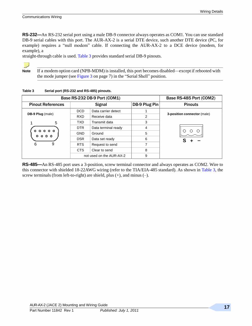
RS-232—An RS-232 serial port using a male DB-9 connector always operates as COM1. You can use standard
DB-9 serial cables with this port. The AUR-AX-2 is a serial DTE device, such another DTE device (PC, for
example) requires a ―null modem‖ cable. If connecting the AUR-AX-2 to a DCE device (modem, for
example), a
straight-through cable is used. Table 3 provides standard serial DB-9 pinouts.
Note If a modem option card (NPB-MDM) is installed, this port becomes disabled—except if rebooted with
the mode jumper (see Figure 3 on page 7) in the ―Serial Shell‖ position.
Table 3 Serial port (RS-232 and RS-485) pinouts.
Base RS-232 DB-9 Port (COM1) Base RS-485 Port (COM2)
Pinout References Signal DB-9 Plug Pin Pinouts
DB-9 Plug (male)
1 5
6 9
DCD Data carrier detect 1 3-position connector (male)
S + –
RXD Receive data 2
TXD Transmit data 3
DTR Data terminal ready 4
GND Ground 5
DSR Data set ready 6
RTS Request to send 7
CTS Clear to send 8
not used on the AUR-AX-2 9
RS-485—An RS-485 port uses a 3-position, screw terminal connector and always operates as COM2. Wire to
this connector with shielded 18-22AWG wiring (refer to the TIA/EIA-485 standard). As shown in Table 3, the
screw terminals (from left-to-right) are shield, plus (+), and minus (–).
AUR-AX-2 (JACE 2) Mounting and Wiring Guide
Rev 1 18
Published: July 1, 2011
Power Up and Initial Checkout
Connect the Backup Battery
Power Up and Initial Checkout
Ensure power wiring to the AUR-AX-2 controller is ready—see the ―Power Wiring‖ section on page 11. Refer
to Figure 3 on page 7 for the locations of the AUR-AX-2 battery connector, status LEDs and barrel power
connector (for WPM-XXX only). Refer to Figure 4 on page 12 for location of the power connector on the NPB-
PWR module.
Following all mounting and wiring, perform the following:
Procedure 4 Initial power up and checkout
Step 1 Connect the Backup Battery.
Step 2 Apply Power.
Step 3 Check the Status LEDs.
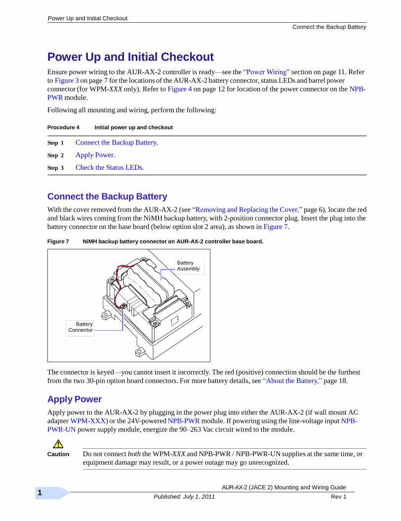
Connect the Backup Battery
With the cover removed from the AUR-AX-2 (see ―Removing and Replacing the Cover,‖ page 6), locate the red
and black wires coming from the NiMH backup battery, with 2-position connector plug. Insert the plug into the
battery connector on the base board (below option slot 2 area), as shown in Figure 7.
Figure 7 NiMH backup battery connector on AUR-AX-2 controller base board.
Battery Assembly
Battery
Connector
The connector is keyed—you cannot insert it incorrectly. The red (positive) connection should be the furthest
from the two 30-pin option board connectors. For more battery details, see ―About the Battery,‖ page 18.
Apply Power
Apply power to the AUR-AX-2 by plugging in the power plug into either the AUR-AX-2 (if wall mount AC
adapter WPM-XXX) or the 24V-powered NPB-PWR module. If powering using the line-voltage input NPB-
PWR-UN power supply module, energize the 90–263 Vac circuit wired to the module.
Caution Do not connect both the WPM-XXX and NPB-PWR / NPB-PWR-UN supplies at the same time, or
equipment damage may result, or a power outage may go unrecognized.

AUR-AX-2 (JACE 2) Mounting and Wiring Guide 19
Part Number 11842 Rev 1 Published: July 1, 2011
Check the Status LEDs
Power Up and Initial Checkout
Check the Status LEDs
When power is applied, the green LED labeled ―STATUS‖ will light. This indicates that the system is OK and
that power is applied. Once the AUR-AX-2 boots, the yellow ―BEAT‖ (heartbeat) LED will begin blinking,
with a typical rate of about 1 Hz. Blinking should begin within 30 seconds after power is applied.
If after applying power, the STATUS LED goes out, or if the BEAT LED comes on (steady) and stays lit longer
than two minutes, contact Systems Engineering for technical assistance. See also the ―Using Status LEDs‖
section on page 19.
About the Battery
The AUR-AX-2 is provided with a custom 10-cell NiMH battery pack mounted to the unit (under the cover).
This battery allows the JACE to continue operation through very short power bumps (a few seconds in
duration). If a longer power outage occurs, the battery provides enough run time for the AUR-AX-2 to backup
data and then shutdown. Typically, this is one minute. Shutdown occurs automatically, after data is backed up
to on-board flash memory.
The AUR-AX-2 charges the battery during normal operation, until fully charged. Typically, the charge
operation completes within 18 hours. Following a power outage, the battery is charged again, as necessary. The
power and battery circuitry is monitored by a station running on the JACE (via the PowerMonitorService).
Station alarms are generated whenever primary power is lost, or if the battery is uncharged or unable to hold a
sufficient charge.
The battery should be replaced approximately every three years, or more often if the unit is in a high temperature
environment.
Note A NiMH battery characteristic is to lose charge if not left in charge mode (trickle charge). Leaving the
battery unconnected, or in the unit powered off will cause the battery to fully discharge in a matter of
weeks. Note that in the case of a new AUR-AX-2, it ships from the factory with a completely
discharged battery. Therefore, allow at least 18 hours for the battery to charge if it has not been in a
powered unit.
For more information on the use and replacement of the battery, refer to the ―Required Battery Maintenance‖
section on page 20.
AUR-AX-2 (JACE 2) Mounting and Wiring Guide
Rev 1 20
Published: July 1, 2011
Using Status LEDs
Ethernet Ports
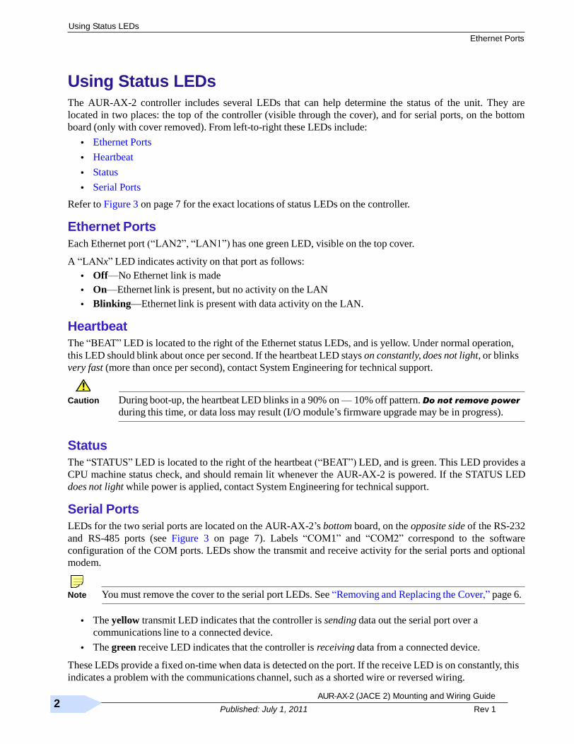
Using Status LEDs
The AUR-AX-2 controller includes several LEDs that can help determine the status of the unit. They are
located in two places: the top of the controller (visible through the cover), and for serial ports, on the bottom
board (only with cover removed). From left-to-right these LEDs include:
• Ethernet Ports
• Heartbeat
• Status
• Serial Ports
Refer to Figure 3 on page 7 for the exact locations of status LEDs on the controller.
Ethernet Ports
Each Ethernet port (―LAN2‖, ―LAN1‖) has one green LED, visible on the top cover.
A ―LANx‖ LED indicates activity on that port as follows:
• Off—No Ethernet link is made
• On—Ethernet link is present, but no activity on the LAN
• Blinking—Ethernet link is present with data activity on the LAN.
Heartbeat
The ―BEAT‖ LED is located to the right of the Ethernet status LEDs, and is yellow. Under normal operation,
this LED should blink about once per second. If the heartbeat LED stays on constantly, does not light, or blinks
very fast (more than once per second), contact System Engineering for technical support.
Caution During boot-up, the heartbeat LED blinks in a 90% on — 10% off pattern. Do not remove power
during this time, or data loss may result (I/O module’s firmware upgrade may be in progress).
Status
The ―STATUS‖ LED is located to the right of the heartbeat (―BEAT‖) LED, and is green. This LED provides a
CPU machine status check, and should remain lit whenever the AUR-AX-2 is powered. If the STATUS LED
does not light while power is applied, contact System Engineering for technical support.
Serial Ports
LEDs for the two serial ports are located on the AUR-AX-2’s bottom board, on the opposite side of the RS-232
and RS-485 ports (see Figure 3 on page 7). Labels ―COM1‖ and ―COM2‖ correspond to the software
configuration of the COM ports. LEDs show the transmit and receive activity for the serial ports and optional
modem.
Note You must remove the cover to the serial port LEDs. See ―Removing and Replacing the Cover,‖ page 6.
• The yellow transmit LED indicates that the controller is sending data out the serial port over a
communications line to a connected device.
• The green receive LED indicates that the controller is receiving data from a connected device.
These LEDs provide a fixed on-time when data is detected on the port. If the receive LED is on constantly, this
indicates a problem with the communications channel, such as a shorted wire or reversed wiring.
AUR-AX-2 (JACE 2) Mounting and Wiring Guide 21
Part Number 11842 Rev 1 Published: July 1, 2011
Cleaning
Maintaining the AUR-AX-2
Maintaining the AUR-AX-2
This section provides information on the following topics:
• Cleaning
• Required Battery Maintenance
• Replacement Parts
• Replacing the AUR-AX-2 base assembly
• Returning a Defective Unit
Cleaning
If dust or metal filings are present inside the unit, clean with vacuum or compressed air. Otherwise, no cleaning
inside the unit is required. Optionally, if the cover becomes dirty, you can wipe it with a damp cloth and mild
detergent.
Required Battery Maintenance
Battery life expectancy is a function of its discharge cycles (the number of discharges and their depth) and the
ambient temperature of the battery during normal operation. In most applications, the battery should see
relatively few discharges. Therefore, ambient temperature has more to do with determining the life expectancy
of the battery than does any other factor. If the AUR-AX-2 is installed in a conditioned space, the battery
should provide dependable service for approximately three years (average). In an environment where the
operating temperature is higher (that is, 50ºC or 122ºF), you should only expect the battery to last approximately
one year.
The NiMH battery in the AUR-AX-2 controller is fully discharged when factory shipped. Additionally, NiMH
batteries lose charge over time if not kept trickle-charged (for more details, see ―About the Battery,‖ page 18).
Therefore, even a new unit (or replacement battery) will require up to 18 hours of powered operation before it
can provide reliable backup power (is at full charge).
The controller monitors the battery and periodically loads the battery to test its ability to maintain battery-backed
functions. Investigate any battery trouble message, and check the battery connections to the unit. Replace the
battery as required. To order a new battery, see the ―Standard Replacement Parts‖ section on page 21.
Replacing the Battery
The replacement NPB-BATT battery is a complete assembly, that is a custom NiMH battery pack pre-attached
to a battery bracket. See Figure 7 on page 17.
Caution Use only battery packs approved for use with the AUR-AX-2
controller. To replace the battery, proceed as follows:
Procedure 5 Replacing NiMH battery assembly on a AUR-AX-2.
Step 1 Backup the controller ’s configuration to your PC using the appropriate NiagaraAX software tool (for
example, Workbench).
Step 2 Remove power from the controller.
Wait for LED activity to stop—after several seconds, all LEDs on the JACE should be off.
Step 3 Remove the cover. See ―Removing and Replacing the Cover,‖ page 6.
AUR-AX-2 (JACE 2) Mounting and Wiring Guide
Rev 1 22
Published: July 1, 2011
Replacement Parts
Non-replaceable Parts
Step 4 Remove the old battery and bracket assembly by taking out the four screws holding it in place, setting
the screws aside for later. Unplug the battery from the connector on the base board.
Step 5 Plug the battery connector plug of the replacement battery into the battery connector on the controller.
Step 6 Set the replacement battery/bracket assembly back over the option card slots, with the mounting holes
aligned with the standoffs.
Step 7 Place the four screws through the battery bracket, option card blanking plates, option cards (if any),
and into the standoffs on the controller’s base board. Using a screwdriver, hand tighten these screws.
Step 8 Replace the cover.
Step 9 Restore power to the controller and verify normal operation.
Replacement Parts
Servicing the AUR-AX-2 controller may call for replacement parts. There are three categories of parts:
• Non-replaceable Parts
• Standard Replacement Parts
• New Replacement Units
Non-replaceable Parts
Other than the parts listed in the replacement parts sections, there are no serviceable components on the base
assembly.
Memory
Any addition, modification, or replacement of memory components requires software configuration and is not
a field upgrade. For additional information on modifying the memory capacity of the AUR-AX-2, consult your
regional Tridium office.
Fuse
The controller contains a non-user replaceable fuse, soldered on the circuit board. This fuse provides protection
from internal shorts or connection to incorrect power supplies. If the fuse circuitry is suspect, contact your
regional Tridium office for technical support. See the ―Returning a Defective Unit‖ section on page 23.
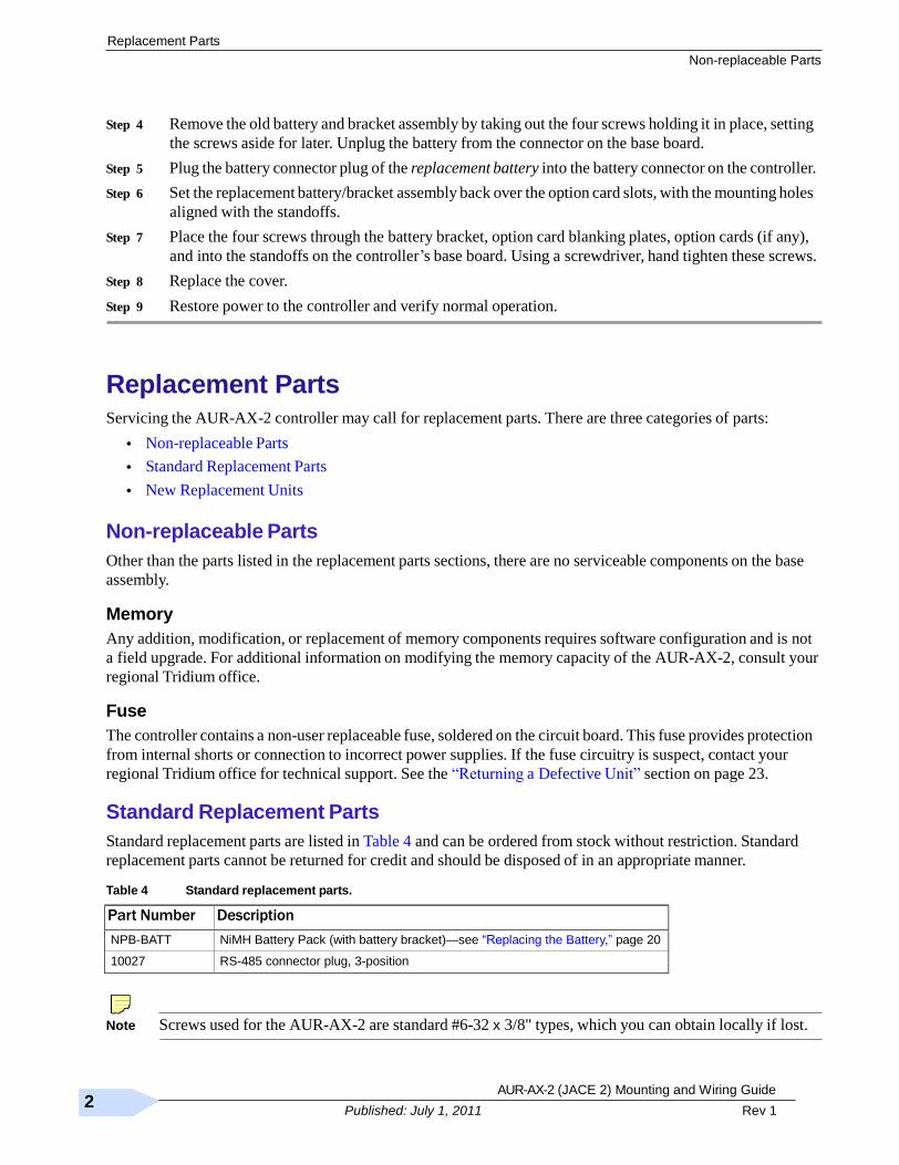
Standard Replacement Parts
Standard replacement parts are listed in Table 4 and can be ordered from stock without restriction. Standard
replacement parts cannot be returned for credit and should be disposed of in an appropriate manner.
Table 4 Standard replacement parts.
Part Number Description
NPB-BATT NiMH Battery Pack (with battery bracket)—see ―Replacing the Battery,‖ page 20
10027 RS-485 connector plug, 3-position
Note Screws used for the AUR-AX-2 are standard #6-32 x 3/8" types, which you can obtain locally if lost.
AUR-AX-2 (JACE 2) Mounting and Wiring Guide 23
Part Number 11842 Rev 1 Published: July 1, 2011
New Replacement Units
Replacement Parts
New Replacement Units
To replace a faulty unit, order and install a new AUR-AX-2 controller—please note this series of products does
not
have special ―field replacement units,‖ or FRUs, with separate part numbers.
If the faulty AUR-AX-2 is still in warranty, you can receive credit by returning it. Be sure to contact the vendor
for a return material authorization (RMA) number before shipping an item for return credit. See ―Returning a
Defective Unit,‖ page 23, for more details.
Note Before ordering a new AUR-AX-2, it is strongly recommended that you contact your normal
technical support resource to eliminate the possibility of a software issue or mis-configuration
problem.
Replacing the AUR-AX-2 base assembly
Caution Before handling circuit boards, discharge any accumulated static by touching the metal surface of
the AUR-AX-2. For details, see the ―Static Discharge Precautions‖ section on page 3.
To replace the AUR-AX-2 base assembly in the field, proceed as follows:
Procedure 6 Replacing an AUR-AX-2 base assembly.
Step 1 Using the appropriate NiagaraAX software tool, back up the controller’s configuration to your PC.
Step 2 Remove power to the controller. The unit should power down automatically.
Wait for all LEDs to remain off.
Note If IO accessory modules are installed, and any I/O points have voltage, turn the devices off or
disconnect power to them.
Step 3 Note positions of all communications and other wiring cables going to the AUR-AX-2, as well as all
installed accessory modules (if they must be removed). If necessary, label connectors and accessory
modules to avoid mis-connection later, after AUR-AX-2 is replaced.
Step 4 Unplug all Ethernet, serial, LON, modem, and I/O connectors from the AUR-AX-2, and unplug its
earth ground wire.
Step 5 If IO accessory modules are installed:
– If DIN rail mounting with DIN end-clips was used, you may be able to remove the DIN rail end clip
that secures the AUR-AX-2 end of the assembly, and then slide the controller away from the rest of
the assembly. Then you can remove the controller from the DIN rail (see Figure 1 on page 6), leaving
the mounting and wiring of IO modules untouched.
In this case, after removing the AUR-AX-2 controller from the DIN rail, skip ahead to Step 6.
– If tab (screw) mounting was used instead of DIN rail mounting, or if a combination of DIN rail
mounting and tab screws (into the AUR-AX-2’s ―accessory side‖ tab holes, see last page), you will
need to remove the accessory modules first, before removing the AUR-AX-2.
AUR-AX-2 (JACE 2) Mounting and Wiring Guide
Rev 1 24
Published: July 1, 2011
Replacement Parts
Returning a Defective Unit
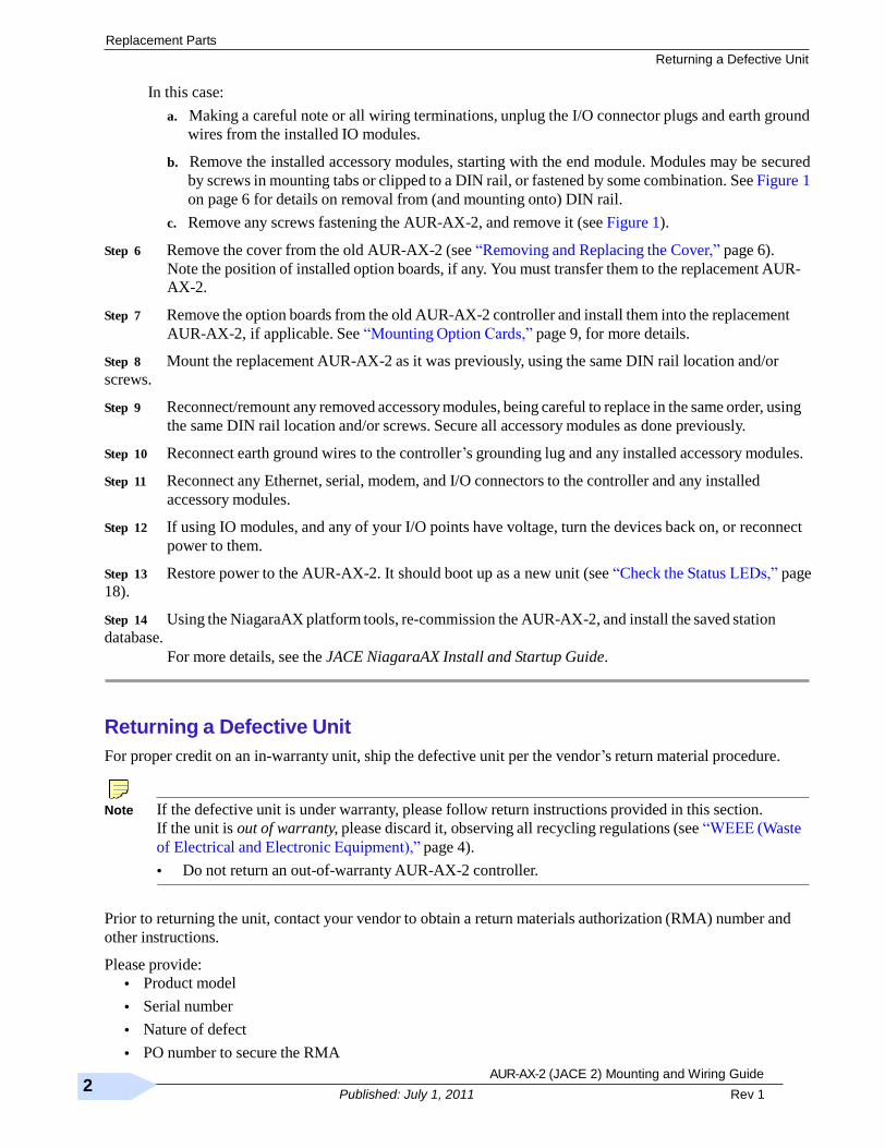
In this case:
a. Making a careful note or all wiring terminations, unplug the I/O connector plugs and earth ground
wires from the installed IO modules.
b. Remove the installed accessory modules, starting with the end module. Modules may be secured
by screws in mounting tabs or clipped to a DIN rail, or fastened by some combination. See Figure 1
on page 6 for details on removal from (and mounting onto) DIN rail.
c. Remove any screws fastening the AUR-AX-2, and remove it (see Figure 1).
Step 6 Remove the cover from the old AUR-AX-2 (see ―Removing and Replacing the Cover,‖ page 6).
Note the position of installed option boards, if any. You must transfer them to the replacement AUR-
AX-2.
Step 7 Remove the option boards from the old AUR-AX-2 controller and install them into the replacement
AUR-AX-2, if applicable. See ―Mounting Option Cards,‖ page 9, for more details.
Step 8 Mount the replacement AUR-AX-2 as it was previously, using the same DIN rail location and/or
screws.
Step 9 Reconnect/remount any removed accessory modules, being careful to replace in the same order, using
the same DIN rail location and/or screws. Secure all accessory modules as done previously.
Step 10 Reconnect earth ground wires to the controller’s grounding lug and any installed accessory modules.
Step 11 Reconnect any Ethernet, serial, modem, and I/O connectors to the controller and any installed
accessory modules.
Step 12 If using IO modules, and any of your I/O points have voltage, turn the devices back on, or reconnect
power to them.
Step 13 Restore power to the AUR-AX-2. It should boot up as a new unit (see ―Check the Status LEDs,‖ page
18).
Step 14 Using the NiagaraAX platform tools, re-commission the AUR-AX-2, and install the saved station
database.
For more details, see the JACE NiagaraAX Install and Startup Guide.
Returning a Defective Unit
For proper credit on an in-warranty unit, ship the defective unit per the vendor’s return material procedure.
Note If the defective unit is under warranty, please follow return instructions provided in this section.
If the unit is out of warranty, please discard it, observing all recycling regulations (see ―WEEE (Waste
of Electrical and Electronic Equipment),‖ page 4).
• Do not return an out-of-warranty AUR-AX-2 controller.
Prior to returning the unit, contact your vendor to obtain a return materials authorization (RMA) number and
other instructions.
Please provide:
• Product model
• Serial number
• Nature of defect
• PO number to secure the RMA

AUR-AX-2 (JACE 2) Mounting and Wiring Guide 25
Part Number 11842 Rev 1 Published: July 1, 2011
Federal Communications Commission (FCC)
Certifications
Certifications Federal Communications Commission (FCC)
This equipment generates, uses, and can radiate radio frequency energy, and if not installed and used in
accordance with the instruction manual, may cause interference with radio communications. It has been tested
and found to comply with the limits for a Class A computing device pursuant to Subpart J of Part 15 of FCC
Rules, which are designed to provide reasonable protection against such interference when operated in a
commercial environment. Operation of this equipment in a residential area may cause interference, in which
case, users at their own expense will be required to take whatever measures may be required to correct the
interference. Any unauthorized modification of this equipment may result in the revocation of the owner's
authority to continue its operation.
Canadian Department of Communications (DOC)
This Class A digital apparatus meets all requirements of the Canadian Interference-Causing Equipment
Regulations.
Cet appareil numerique de la classe A respecte toutes les exigencies du Reglement sur le material broilleur du
Canada.
Declaration of RoHS Compliance This product meets all requirements of RoHS Directive (EU 202/95/EC). All components used in this product
are RoHS compliant, and there have been no leaded solders used in manufacture.
Related to the RoHS (Restriction of Hazardous Substances) Directive is another European Directive
2002/96/EC on Waste Electrical and Electronic Equipment (WEEE). The WEEE Directive aims to reduce the
waste arising from electrical and electronic equipment, and improve the environmental performance of
everything involved in the life cycle of electrical and electronic equipment.
For related details, see the precaution ―WEEE (Waste of Electrical and Electronic Equipment)‖ on page 4.
AUR-AX-2 (JACE 2) Mounting and Wiring Guide
Rev 1 26
Published: July 1, 2011
Certifications
CE Declaration of Conformity
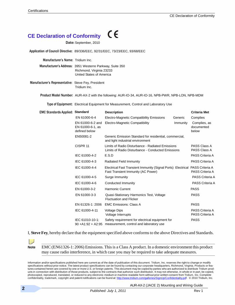
CE Declaration of Conformity Date: September, 2010
Application of Council Directive: 89/336/EEC, 92/31/EEC, 73/23/EEC, 93/68/EEC
Manufacturer’s Name: Tridium Inc.
Manufacturer’s Address: 3951 Westerre Parkway, Suite 350
Richmond, Virginia 23233
United States of America
Manufacturer’s Representative: Steve Fey, President
Tridium Inc.
Product Model Number: AUR-AX-2 with the following: AUR-IO-34, AUR-IO-16, NPB-PWR, NPB-LON, NPB-MDM
Type of Equipment: Electrical Equipment for Measurement, Control and Laboratory Use
EMC Standards Applied: Standard
EN 61000-6-4
Description
Electro-Magnetic Compatibility Emissions Generic
Criteria Met
Complies
EN 61000-6-2 and
EN 61000-6-1, as
defined below
Electro-Magnetic Compatibility Immunity Complies, as
documented
below
EN50081-2 Generic Emission Standard for residential, commercial,
and light industrial environment
CISPR 11 Limits of Radio Disturbance - Radiated Emissions
Limits of Radio Disturbance - Conducted Emissions
PASS Class A
PASS Class A
IEC 61000-4-2 E.S.D PASS Criteria A
IEC 61000-4-3 Radiated Field Immunity PASS Criteria A
IEC 61000-4-4 Electrical Fast Transient Immunity (Signal Ports) Electrical PASS Criteria A
Fast Transient Immunity (AC Power) PASS Criteria A
IEC 61000-4-5 Surge Immunity PASS Criteria A
IEC 61000-4-6 Conducted Immunity PASS Criteria A
EN 61000-3-2 Harmonic Current PASS
EN 61000-3-3 Quasi-Stationary Harmonics Test, Voltage
Fluctuation and Flicker
PASS
EN 61326-1: 2006 EMC Emissions: Class A PASS
IEC 61000-4-11 Voltage Dips
Voltage Interrupts
PASS Criteria A
PASS Criteria A
IEC 61010-10-1:
90 +A1:92 + A2:95
Safety requirement for electrical equipment for
measurement, control and laboratory use
PASS
I, Steve Fey, hereby declare that the equipment specified above conforms to the above Directives and Standards.
Note EMC (EN61326-1: 2006) Emissions. This is a Class A product. In a domestic environment this product
may cause radio interference, in which case you may be required to take adequate measures.
Information and/or specifications published here are current as of the date of publication of this document. Tridium, Inc. reserves the right to change or modify specifications without prior notice. The latest product specifications can be found by contacting our corporate headquarters, Richmond, Virginia. Products or fea- tures contained herein are covered by one or more U.S. or foreign patents. This document may be copied by parties who are authorized to distribute Tridium prod- ucts in connection with distribution of those products, subject to the contracts that authorize such distribution. It may not otherwise, in whole or in part, be copied, photocopied, reproduced, translated, or reduced to any electronic medium or machine-readable form without prior written consent from Tridium, Inc. Complete confidentiality, trademark, copyright and patent notifications can be found at: http://www.tridium.com/galleries/SignUp/Confidentiality.pdf. © 2010 Tridium, Inc.
AUR-AX-2 (JACE 2) Mounting and Wiring Guide 27
Part Number 11842 Rev 1 Published: July 1, 2011
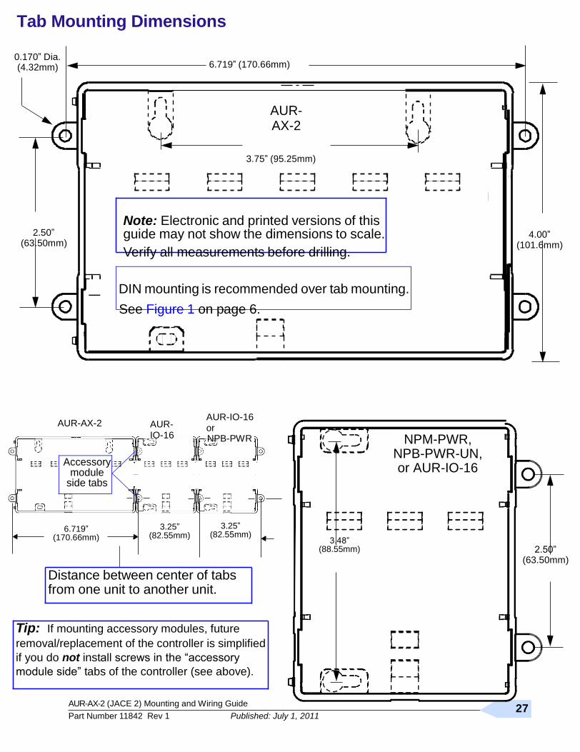
Tab Mounting Dimensions
0.170‖ Dia. (4.32mm)
6.719‖ (170.66mm)
AUR-AX-2
3.75‖ (95.25mm)
2.50‖
(63.50mm)
Note: Electronic and printed versions of this guide may not show the dimensions to scale.
Verify all measurements before drilling.
4.00‖ (101.6mm)
DIN mounting is recommended over tab mounting.
See Figure 1 on page 6.
AUR-AX-2
Accessory module
side tabs
AUR-IO-16
AUR-IO-16 or NPB-PWR
NPM-PWR,
NPB-PWR-UN, or AUR-IO-16
6.719‖ (170.66mm)
3.25‖ (82.55mm)
3.25‖ (82.55mm)
3.48‖ (88.55mm)
2.50‖ (63.50mm)
Distance between center of tabs from one unit to another unit.
Tip: If mounting accessory modules, future
removal/replacement of the controller is simplified
if you do not install screws in the ―accessory
module side‖ tabs of the controller (see above).