Embed Size (px)
Citation preview
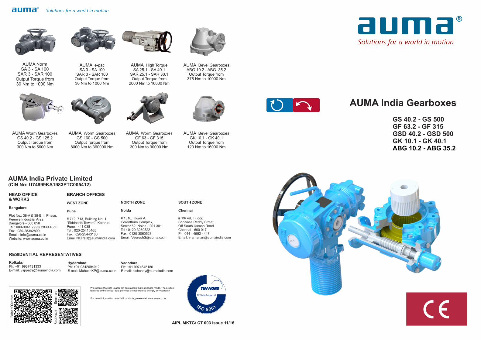
AUMA Worm GearboxesGS 40.2 - GS 125.2Output Torque from300 Nm to 5600 Nm
AUMA Worm GearboxesGS 160 - GS 500
Output Torque from8000 Nm to 360000 Nm
AUMA Worm GearboxesGF 63 - GF 315
Output Torque from300 Nm to 90000 Nm
AUMA Bevel GearboxesGK 10.1 - GK 40.1Output Torque from
120 Nm to 16000 Nm
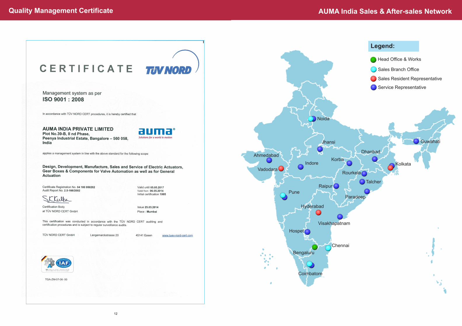
HEAD OFFICE & WORKS
Bangalore
Plot No.: 38-A & 39-B, II Phase, Peenya Industrial Area,Bangalore - 560 058Tel : 080-3041 2222/ 2839 4656 Fax : 080-28392809Email : [email protected]: www.auma.co.in
BRANCH OFFICES
WEST ZONE
Pune
# 712, 713, Building No. 1, “Siddharth Towers”, Kothrud, Pune - 411 038Tel : 020-25410465Fax : 020-25443186Email:[email protected]
NORTH ZONE
Noida
# 1310, Tower A, Corenthum Complex, Sector 62, Noida - 201 301 Tel : 0120-3060522 Fax : 0120-3060523 Email: [email protected]
SOUTH ZONE
Chennai
# 19/ 49, I Floor,Srinivasa Reddy Street,Off South Usman RoadChennai - 600 017Ph: 044 - 4552 4447Email: [email protected]
AUMA India Private Limited(CIN No: U74999KA1983PTC005412)
Kolkata:Ph: +91 9937431333E-mail: [email protected]
Vadodara: Ph: +91 9974645180E-mail: [email protected]
Hyderabad:Ph: +91 9342694012E-mail: [email protected]
RESIDENTIAL REPRESENTATIVES
AUMA NormSA 3 - SA 100
SAR 3 - SAR 100Output Torque from 30 Nm to 1000 Nm
AUMA e-pacSA 3 - SA 100
SAR 3 - SAR 100Output Torque from 30 Nm to 1000 Nm
AUMA High TorqueSA 25.1 - SA 40.1
SAR 25.1 - SAR 30.1Output Torque from
2000 Nm to 16000 Nm
AUMA Bevel Gearboxes ABG 10.2 - ABG 35.2
Output Torque from375 Nm to 10000 Nm
We reserve the right to alter the data according to changes made. The product features and technical data provided do not express or imply any warranty.
For latest information on AUMA products, please visit www.auma.co.in
AUMA India Gearboxes
GS 40.2 - GS 500GF 63.2 - GF 315GSD 40.2 - GSD 500GK 10.1 - GK 40.1ABG 10.2 - ABG 35.2
AIPL MKTG/ CT 003 Issue 11/16
Introduction 1
Applications 2
AUMA India Gearboxes 3-5
Specification for Part-turn Worm Gearboxes
6
Specification for Multi-turn Bevel Gearboxes
7
Features & Benefits of AUMA India Worm Gearboxes
8
Actuator / Gearbox Selection Procedure 9-10
Service Condition & Certificates 11
Quality Management Certificate 12
Table of Contents: Gearbox Catalogue
Note: There are various features and options that are available other than what is listed in the catalogue. For special needs, please contact AUMA India.
Armaturen-UndMaschinen-Antriebe
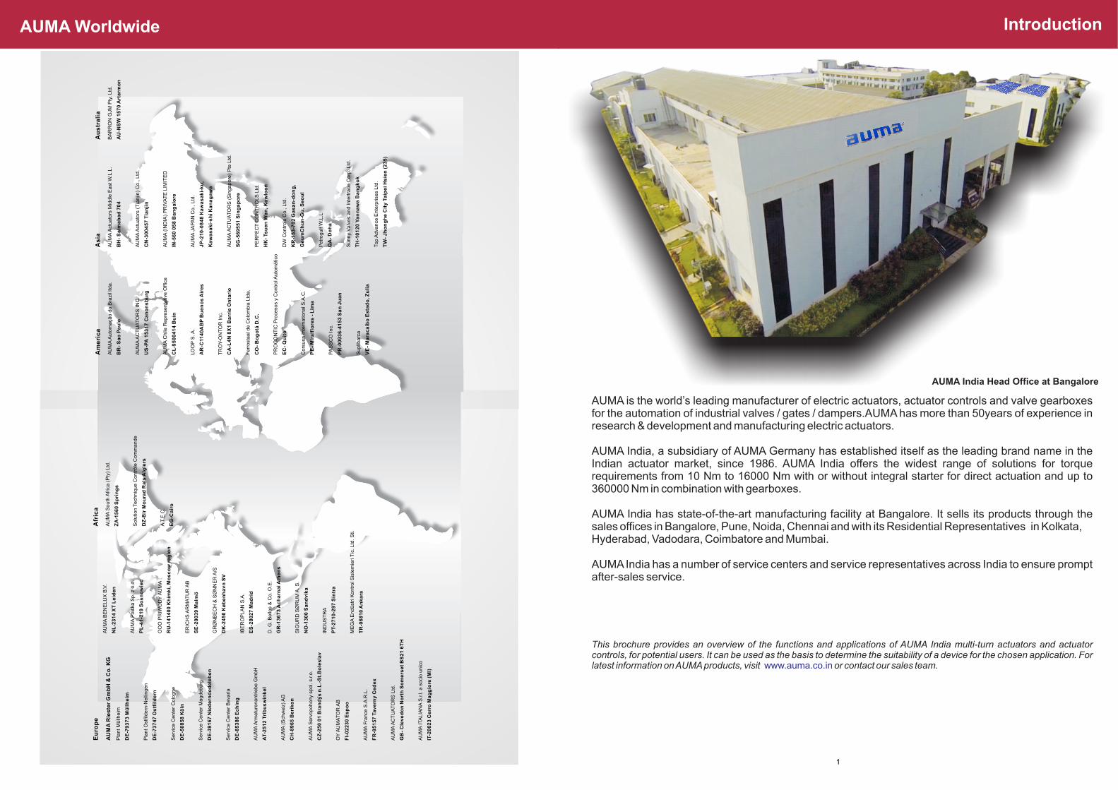
AUMA WorldwideA
UM
A w
orl
dw
ide
AU
MA
wo
rld
wid
e
Eu
rop
e
AU
MA
Rie
ste
r G
mb
H &
Co
. K
G
Pla
nt M
üllh
eim
DE
-79
37
3 M
üll
he
im
Pla
nt O
stfi ld
ern
-Nelli
ngen
DE
-73
74
7 O
stf
ild
ern
Serv
ice C
ente
r C
olo
gne
DE
-50
85
8 K
öln
Serv
ice C
ente
r M
agdeburg
DE
-39
16
7 N
ied
ern
do
de
leb
en
Serv
ice C
ente
r B
ava
ria
DE
-85
38
6 E
ch
ing
AU
MA
Arm
atu
renantr
iebe G
mbH
AT-2
51
2 T
rib
us
win
ke
l
AU
MA
(S
chw
eiz
) A
G
CH
-89
65 B
eri
ko
n
AU
MA
Serv
opohony
spol.
s.r.o.
CZ
-25
0 0
1 B
ran
dý
s n
.L.-
St.
Bo
les
lav
OY
AU
MA
TO
R A
B
FI-
02
23
0 E
sp
oo
AU
MA
Fra
nce
S.A
.R.L
.
FR
-95
15
7 T
av
ern
y C
ed
ex
AU
MA
AC
TU
AT
OR
S L
td.
GB
- C
lev
ed
on
No
rth
So
me
rse
t B
S2
1 6
TH
AU
MA
IT
ALIA
NA
S.r.l.
a s
oci
o u
nic
o
IT-2
00
23 C
err
o M
ag
gio
re (
MI)
AU
MA
BE
NE
LU
X B
.V.
NL
-23
14 X
T L
eid
en
AU
MA
Pols
ka S
p. z
o.o
.
PL
-41
-21
9 S
os
no
wie
c
OO
O P
RIW
OD
Y A
UM
A
RU
-14
14
00 K
him
ki,
Mo
sc
ow
re
gio
n
ER
ICH
S A
RM
AT
UR
AB
SE
-20
03
9 M
alm
ö
GR
ØN
BE
CH
& S
ØN
NE
R A
/S
DK
-24
50 K
øb
en
ha
vn
SV
IBE
RO
PLA
N S
.A.
ES
-28
02
7 M
ad
rid
D. G
. B
ello
s &
Co. O
.E.
GR
-13
67
3 A
ch
arn
ai A
the
ns
SIG
UR
D S
ØR
UM
A. S
.
NO
-13
00 S
an
dv
ika
IND
US
TR
A
PT-2
71
0-2
97 S
intr
a
ME
GA
Endüst
ri K
ontr
ol S
iste
mie
ri T
ic. Ltd
. S
ti.
TR
-06
81
0 A
nk
ara
Afr
ica
AU
MA
South
Afr
ica (
Pty
) Ltd
.
ZA
-15
60 S
pri
ng
s
Solu
tion T
ech
niq
ue C
ontr
ôle
Com
mande
DZ
-Bir
Mo
ura
d R
ais
Alg
iers
A.T
.E.C
.
EG
-Ca
iro
Am
eri
ca
AU
MA
Auto
maçã
o d
o B
razi
l ltda.
BR
- S
ao
Pa
ulo
AU
MA
AC
TU
AT
OR
S IN
C.
US
-PA
15
31
7 C
an
on
sb
urg
AU
MA
Chile
Repre
senta
tive
Offi c
e
CL
-95
00
41
4 B
uin
LO
OP
S. A
.
AR
-C11
40
AB
P B
ue
no
s A
ire
s
TR
OY
-ON
TO
R Inc.
CA
-L4
N 8
X1 B
arr
ie O
nta
rio
Ferr
ost
aal d
e C
olo
mbia
Ltd
a.
CO
- B
og
otá
D.C
.
PR
OC
ON
TIC
Pro
ceso
s y
Contr
ol A
uto
mático
EC
- Q
uit
o
Cors
usa
Inte
rnatio
nal S
.A.C
.
PE
- M
ira
lflo
res -
Lim
a
PA
SS
CO
Inc.
PR
-00
93
6-4
15
3 S
an
Ju
an
Suplib
arc
a
VE
- M
ara
ca
ibo
Es
tad
o, Z
uli
a
As
ia
AU
MA
Act
uato
rs M
iddle
East
W.L
.L.
BH
- S
alm
ab
ad
70
4
AU
MA
Act
uato
rs (
Tia
njin
) C
o., L
td.
CN
-30
04
57 T
ian
jin
AU
MA
(IN
DIA
) P
RIV
AT
E L
IMIT
ED
IN-5
60 0
58 B
an
ga
lore
AU
MA
JA
PA
N C
o., L
td.
JP
-21
0-0
84
8 K
aw
as
ak
i-k
u,
Ka
wa
sa
ki-
sh
i K
an
ag
aw
a
AU
MA
AC
TU
AT
OR
S (
Sin
gapore
) P
te L
td.
SG
-56
95
51 S
ing
ap
ore
PE
RF
EC
T C
ON
TR
OLS
Ltd
.
HK
- T
su
en
Wa
n, K
ow
loo
n
DW
Contr
ols
Co., L
td.
KR
-15
3-7
02 G
as
an
-do
ng
,
Ge
um
Ch
un
-Gu
, S
eo
ul
Petr
ogulf W
.L.L
QA
- D
oh
a
Sunny
Valv
es
and Inte
rtra
de C
orp
. Ltd
.
TH
-10
12
0 Y
an
na
wa B
an
gk
ok
Top A
dva
nce
Ente
rprise
s Ltd
.
TW
- J
ho
ng
he C
ity T
aip
ei H
sie
n (
23
5)
Au
str
ali
a
BA
RR
ON
GJM
Pty
. Ltd
.
AU
-NS
W 1
57
0 A
rta
rmo
n
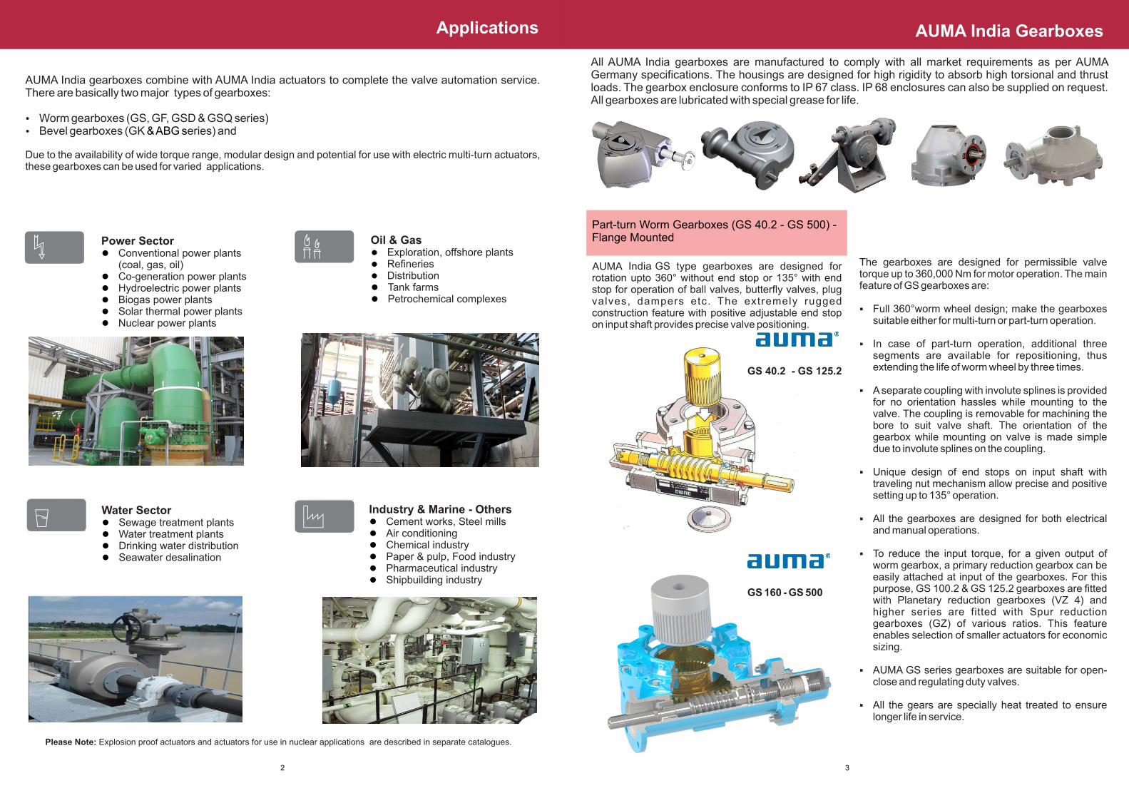
AUMA India Head Office at Bangalore
Introduction
1
Part-turn Worm Gearboxes (GS 40.2 - GS 500) - Flange Mounted
The gearboxes are designed for permissible valve torque up to 360,000 Nm for motor operation. The main feature of GS gearboxes are:
§ Full 360°worm wheel design; make the gearboxes suitable either for multi-turn or part-turn operation.
§ In case of part-turn operation, additional three segments are available for repositioning, thus extending the life of worm wheel by three times.
§ A separate coupling with involute splines is provided for no orientation hassles while mounting to the valve. The coupling is removable for machining the bore to suit valve shaft. The orientation of the gearbox while mounting on valve is made simple due to involute splines on the coupling.
§ Unique design of end stops on input shaft with traveling nut mechanism allow precise and positive setting up to 135° operation.
§ All the gearboxes are designed for both electrical and manual operations.
§ To reduce the input torque, for a given output of worm gearbox, a primary reduction gearbox can be easily attached at input of the gearboxes. For this purpose, GS 100.2 & GS 125.2 gearboxes are fitted with Planetary reduction gearboxes (VZ 4) and higher series are fitted with Spur reduction gearboxes (GZ) of various ratios. This feature enables selection of smaller actuators for economic sizing.
§ AUMA GS series gearboxes are suitable for open-close and regulating duty valves.
§ All the gears are specially heat treated to ensure longer life in service.
AUMA India Gearboxes
All AUMA India gearboxes are manufactured to comply with all market requirements as per AUMA Germany specifications. The housings are designed for high rigidity to absorb high torsional and thrust loads. The gearbox enclosure conforms to IP 67 class. IP 68 enclosures can also be supplied on request. All gearboxes are lubricated with special grease for life.
3
AUMA
Applications
Please Note: Explosion proof actuators and actuators for use in nuclear applications are described in separate catalogues.
AUMA India gearboxes combine with AUMA India actuators to complete the valve automation service. There are basically two major types of gearboxes:
Ÿ Worm gearboxes (GS, GF, GSD & GSQ series)Ÿ Bevel gearboxes (GK eries) and & ABG s Due to the availability of wide torque range, modular design and potential for use with electric multi-turn actuators, these gearboxes can be used for varied applications.
Power Sector l Conventional power plants
(coal, gas, oil)l Co-generation power plantsl Hydroelectric power plantsl Biogas power plantsl Solar thermal power plantsl Nuclear power plants
Water Sector l Sewage treatment plantsl Water treatment plantsl Drinking water distributionl Seawater desalination
Industry & Marine - Others l Cement works, Steel millsl Air conditioningl Chemical industryl Paper & pulp, Food industryl Pharmaceutical industryl Shipbuilding industry
Oil & Gas l Exploration, offshore plantsl Refineriesl Distributionl Tank farmsl Petrochemical complexes
2
Auma India Gearboxes
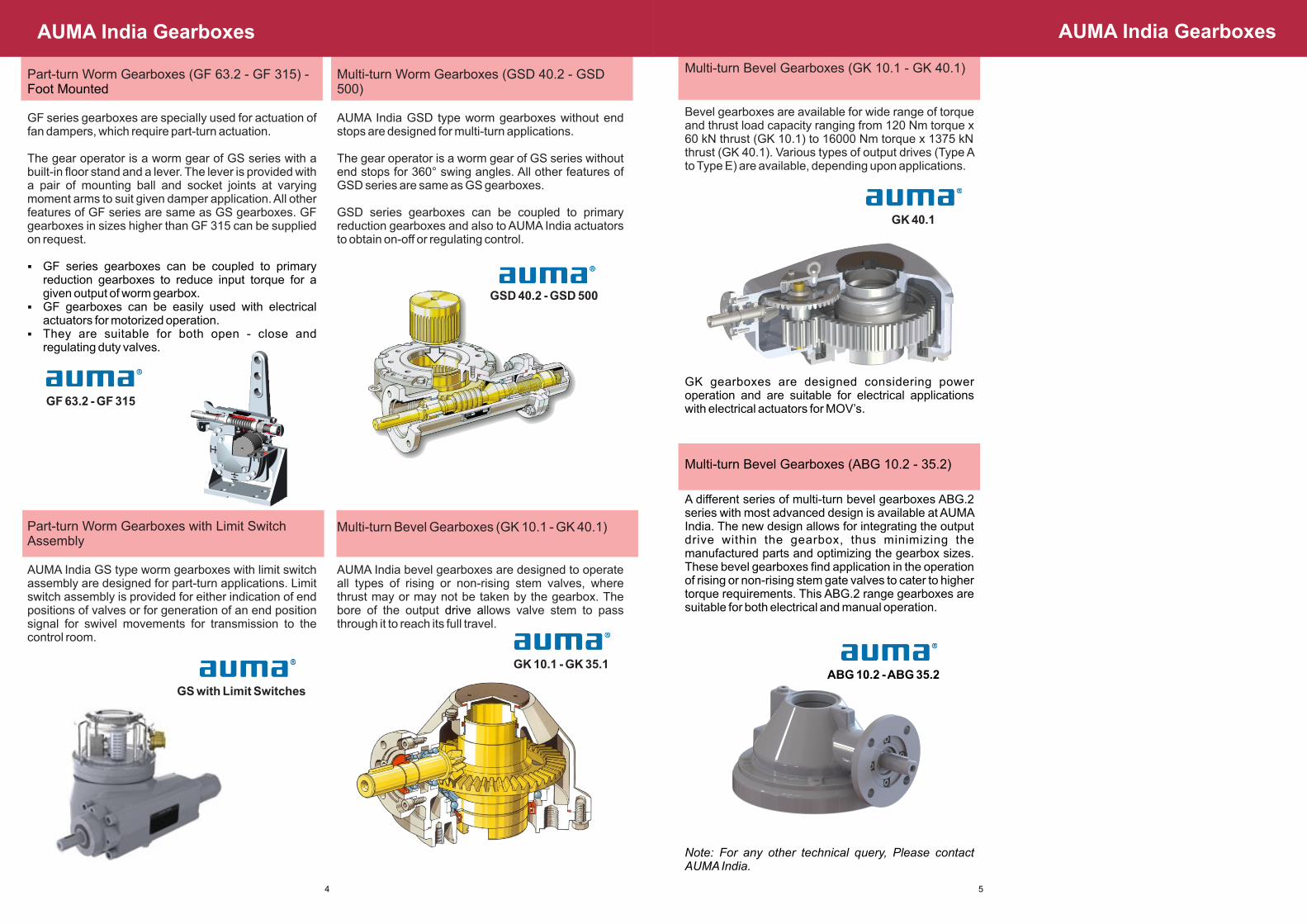
Multi-turn Bevel Gearboxes (GK 10.1 - GK 40.1)
Bevel gearboxes are available for wide range of torque and thrust load capacity ranging from 120 Nm torque x 60 kN thrust (GK 10.1) to 16000 Nm torque x 1375 kN thrust (GK 40.1). Various types of output drives (Type A to Type E) are available, depending upon applications.
GK 40.1
GK gearboxes are designed considering power operation and are suitable for electrical applications with electrical actuators for MOV’s.
Multi-turn Bevel Gearboxes (ABG 10.2 - 35.2)
A different series of multi-turn bevel gearboxes ABG.2 series with most advanced design is available at AUMA India. The new design allows for integrating the output drive within the gearbox, thus minimizing the manufactured parts and optimizing the gearbox sizes. These bevel gearboxes find application in the operation of rising or non-rising stem gate valves to cater to higher torque requirements. This ABG.2 range gearboxes are suitable for both electrical and manual operation.
ABG 10.2 - ABG 35.2
Note: For any other technical query, Please contact AUMA India.
AUMA India Gearboxes
5
Part-turn Worm Gearboxes (GF 63.2 - GF 315) - Foot Mounted
Multi-turn Worm Gearboxes (GSD 40.2 - GSD 500)
GF series gearboxes are specially used for actuation of fan dampers, which require part-turn actuation.
The gear operator is a worm gear of GS series with a built-in floor stand and a lever. The lever is provided with a pair of mounting ball and socket joints at varying moment arms to suit given damper application. All other features of GF series are same as GS gearboxes. GF gearboxes in sizes higher than GF 315 can be supplied on request.
§ GF series gearboxes can be coupled to primary reduction gearboxes to reduce input torque for a given output of worm gearbox.
§ GF gearboxes can be easily used with electrical actuators for motorized operation.
§ They are suitable for both open - close and regulating duty valves.
GF 63.2 - GF 315
AUMA India GSD type worm gearboxes without end stops are designed for multi-turn applications.
The gear operator is a worm gear of GS series without end stops for 360° swing angles. All other features of GSD series are same as GS gearboxes.
GSD series gearboxes can be coupled to primary reduction gearboxes and also to AUMA India actuators to obtain on-off or regulating control.
GSD 40.2 - GSD 500
Multi-turn Bevel Gearboxes (GK 10.1 - GK 40.1)Part-turn Worm Gearboxes with Limit Switch Assembly
AUMA India GS type worm gearboxes with limit switch assembly are designed for part-turn applications. Limit switch assembly is provided for either indication of end positions of valves or for generation of an end position signal for swivel movements for transmission to the control room.
GS with Limit Switches
AUMA India bevel gearboxes are designed to operate all types of rising or non-rising stem valves, where thrust may or may not be taken by the gearbox. The bore of the output llows valve stem to pass drive athrough it to reach its full travel.
GK 10.1 - GK 35.1
AUMA India Gearboxes
4
Specification for Multi-turn Bevel Gearboxes
1. All gearboxes shall have bevel gear transmission with completely enclosed construction. The gear casing
shall be designed adequately to withstand shock and vibration of the pipeline. The design shall be
compact and of light weight and shall not cause any trouble during operation at sites.
2. The gearbox shall be filled with grease. The specification of lubricant i.e., grease, shall be furnished. There
shall be no leakage of lubricant from the gearbox.
3. The gearbox shall be suitable for mounting in any position to suit the site requirements.
4. It shall be possible to use the same gearbox for different applications (rising and non-rising stem) by
changing only the output drive of the gearbox.
5. The gearbox shall have a base suitable to take the thrust with needle roller bearing. A blank high tensile
brass or aluminum bronze drive sleeve shall be provided as a standard supply.
6. The assembly of all gears, shafts etc., shall be done properly to have smooth, noise free operation.
7. The flange for connecting the valve shall have dimensions as per DIN 3210 / ISO 5210 standards.
8. Wherever gearboxes are required to be assembled with electrical actuators, gearboxes are to be supplied
with input flanges to suit the keyed shaft of the actuator. The design should be suitable for both manual as
well as electrical operation.
9. The bevel pinion shall be of case hardened steel and gear of alloy steel EN19 / SG Iron 600/3 with suitable
heat treatment.
10. All gearboxes shall have stem protection covers for rising stem application.
11. The gearbox shall be painted with corrosion protection epoxy based paint.
12. The gearbox shall be enclosed to a minimum of IP 67 protection class.
13. Gearboxes shall be suitable for an ambient temperature range of -20°C to +80°C. Other
temperatures on request.
14. Supplier will furnish the general arrangement drawing of the gearbox incorporating the material
specification for all critical components and overall dimensional details for approval.
15. The gearbox shall be tested to the design requirement of torque / thrust wherever applicable and type test
certificates shall be furnished.
7
FOOT MOUNTED SECONDARY WORM GEARBOX - GF2.
FLANGE MOUNTED SECONDARY WORM GEARBOX - GS1.
1.1 The secondary worm gearbox shall be so selected that in combination with Electrical actuator, it
shall meet specified torque and operating time.
1.2 Secondary gearbox shall be flange mounted.
1.3 The secondary gearbox shall be self-locking, having 360° full worm wheel. It shall be possible to
position and use extra 3 quadrants of worm wheel available.
1.4 Gearbox shall be provided with adjustable mechanical stoppers (traveling nut arrangement) on the
input shaft so that only the input torque is sensed, ensuring safety and to have positive feeling when
end position is reached while operating manually.
1.5 The gearbox shall be provided with adjustable mechanical stopper arrangement adjustable from
80° to 120°angle of travel.
1.6 The secondary gearbox shall have minimum IP 67 protection class.
1.7 The gearbox housing shall be grease filled and suitable for any position mounting. (Refer page 7 for
more information)
1.8 A separate splined coupling shall be provided for fixing the gearbox on to valve to avoid orientation
problems while mounting.
1.9 It shall be possible to change the version of the gearbox for the following operation:
a. Clockwise rotation at the input shaft of gearbox, resulting in clockwise rotation of the valve shaft.
b. Clockwise rotation at the input shaft of gearbox, resulting in anti-clockwise rotation of the valve
shaft.
This shall be an inherent feature of the gearbox, to have maximum flexibility at site.
1.10 An adjustable mechanical pointer cover to show valve position shall be available.
1.11 The gearbox shall be painted with corrosion proof epoxy resin paint. Paint shade shall be
manufacturer's standard.
1.12 Gearboxes shall be suitable for an ambient temperature range of -20°C to +80°C. Other
temperatures on request.
2.1 The secondary Worm gearbox shall be so selected that in combination with electrical actuator, it
shall meet specified torque and operating time.
2.2 Secondary gearbox shall be foot mounted with lever arrangement design.
2.3 The secondary gearbox shall be self-locking having 360° full worm wheel. It shall be possible to
position and use extra 3 quadrants of worm wheel available.
2.4 Gearbox shall be provided with adjustable mechanical stoppers (traveling nut arrangement) on the
input shaft so that only the input torque is sensed, ensuring safety and to have positive feeling when
end position is reached while operating manually.
2.5 The gearbox shall be provided with adjustable mechanical stopper arrangement adjustable from 80°
to 120° angle of travel.
2.6 The secondary gearbox shall have minimum IP 67 protection class.
2.7 The gearbox housing shall be grease filled and suitable for any position mounting. (Refer page 7 for
more information)
2.8 It shall be possible to change the version of the gearbox for the following operation:
a. Clockwise rotation at the input shaft of gearbox, resulting in clockwise rotation of the valve shaft.
b. Clockwise rotation at the input shaft of gearbox, resulting in anti-clockwise rotation of the valve
shaft.
This shall be an inherent feature of the gearbox, to have maximum flexibility at site.
2.9 An adjustable mechanical pointer cover to show valve position shall be available.
2.10 The gearbox shall be painted with corrosion proof epoxy resin paint. Paint shade shall be
manufacturer's standard.
2.11 Gearboxes shall be suitable for an ambient temperature range of -20°C to +80°C. Other
temperatures can be provided on request.
Specification for Part-turn Worm Gearboxes
6
Actuator / Gearbox Selection Procedure
LINEAR OR MULTI-TURN VALVES(Eg: GATE, GLOBE, DIAPHRAGM TYPE ETC.)
For output thrust up to 190 kN and output torque up to 100 kgm, AUMA multi-turn actuators can be directly selected and mounted on the valve. However, AUMA also offers bevel gearboxes type “GK” and spur gearboxes type “GST” for up to and higher torque / thrust requirements.
Data required for proper sizing:
§ Type of valve§ Max. thrust incase of rising stem valves§ Max. torque incase of rotating stem valves§ Type of service / duty§ No. of turns of stem per stroke or stroke and stem
thread details§ Operating time§ Stem diameter§ Mounting details
Sizing Examples:
Minimum data:§ Max. thrust = 300 kN = 30000kgf§ No. of turns / stroke = 20§ Operating time = 60 secs.§ Open-Close duty
Step 1 : Selection of Gearbox
§ Refer “Technical Data” and “Output Drive Types” of gearboxes (GK 10.1 - 40.1) in catalogue
§ For rising stem valves, always select output drive ‘type A’
§ Select gearbox type whose max. thrust permissible is more than or equal to required thrust
In this case, gearbox type is GK 25.1, whose maximum thrust permissible is 320 kN.
Step 2 : Selection of Actuator
§ Referring to the “Technical Data” of Gearbox catalogue (GK 10.1 - 40.1), suitable actuator model given in the table is to be selected.
§ The required output rpm of the actuator can be calculated as follows:
Actuator output rpm =
No. of turns of valve / stroke x reduction ratio of gearbox x 60Operating time in secs.
In this case, suitable actuator model is SA 50and Actuator output rpm = 20 x 6 x 60 60 = 120 rpm
Choose the nearest available actuator output speed (refer AUMA Actuator catalogue for details) i.e. 125 rpm.
Hence, the selected combination is GK25.1A/SA50E125 and the revised operating time ~ 52 secs.
Where actuator designation SA50E125 indicates open-close duty actuator SA50 with output drive type E having output rpm of 125.
Note: When couplingAUMA actuator with AUMA gearbox, always employ output drive type ‘E’.
After selecting the suitable model, the following points should be verified:
§ Output torque values (refer “Technical Data” for details).
§ Max. stem acceptance dia. (refer “Technical Data” and “”Output Drive” for details)
§ Mounting flange compatibility (refer “Technical Data” and “Output Drive” for details).
Note: 1. In case of multi-turn, non-rising (rotating) stem valves, same selection procedure should be followed except for the following:
§ Output torque values are to be compared and evaluated
§ Output drive types B, C, D or E should be selected, depending on type of coupling required (normally, the output drive type will be either ‘B’ or ‘E’)
9
Features & Benefits of AUMA India Worm Gearboxes
FEATURES BENEFITS
Rigid Casting Ÿ Strong and Reliable
Manufactured according to AUMA Germany Drawings
Ÿ Reliable, proven design, German know-how
360° Worm wheelŸ Enhanced life since 3 extra segments are
available for future use
Removable Splined coupling Ÿ No orientation hassles
Enclosure protection : IP 67 Ÿ Safe for outdoor applications
Grease lubricationŸ Ensures smooth operationŸ Freedom of “any position mounting”
Mechanical end stoppers at the gearbox inputŸ Allows easy setting for the desired output travelŸ Imparts a positive feeling when end positions
are reached, during manual operation
Only input torque is sensed by the mechanical stoppers (and not the output torque which is very high)
Ÿ No chance of damage to gearbox housing
Available with various reduction ratiosŸ Meets different operating time requirement and
optimizes electrical actuator selection
High mechanical advantageŸ Results in lesser input torque requirement, thus
optimizing electrical actuator selection
Different versionsŸ Provides “choice of selection” to meet plant
requirement
8
Service Condition and Certificates
Declaration of Incorporation
Declaration of incorporation in accordance with Machinery Directive
According to the EU directives, AUMA actuators, actuator controls and valve gearboxes are not machines. This means that a declaration of conformity in accordance with the Machinery Directive cannot be issued by AUMA . AUMA’s Declaration of Incorporation confirms that during the design stage of the devices, the standards mentioned in the Machinery Directive were applied, The declaration of Incorporation are included in the operation instruction of the devices.
Only by mounting the devices to other components (valves, pipelines, etc. ) a ‘machine’ within the meaning of the directive is formed. Before commissioning this machine a certificate of conformity must be issued.
Compulsory marking with CE mark
AUMA products meet the requirements of the mentioned EU directives. The name plate therefore is marked with the CE mark.
Enclosure Protection Painting
AUMA gearboxes conform to enclosure protection IP 67 as per IS / IEC 60529. The definition of IP 67 as per standard is as follows :
IP : Ingress Protection
First Numeral 6 : Dust tight, prevents ingress of dust.
Second Numeral 7 : Protected against the effects of immersion. Test is done by completely immersing the equipment in water so that:
l Surface of water is at least 150 mm above highest point of equipment.
l The lowest point of equipment is at least 1 m below the surface of water.
l Duration of test is 30 min.
Under above conditions, ingress of water in harmful quantity shall not be possible.
AUMA India gearboxes can also be offered with IP 68 enclosure protection on request.
Other paints & color can be provided based on mutually agreed customer requirement.
11
Type of Paint Epoxy/ Polyurethane
Standard Color Smoke Grey 692
Zinc Phosphate Epoxy Primer Thickness
50 microns
Epoxy Thickness (Finish)
60 microns
C3 - EN ISO 12944-2
Actuator / Gearbox Selection Procedure
10
PART-TURN VALVES (Eg: BUTTERFLY, BALL, PLUG, LOUVRE DAMPERS ETC.)
In part-turn valves, the final movement of valve shaft required is normally 90°. The electrical actuators are primarily multi-turn type and hence, it is necessary to employ an intermediate worm gearbox between the actuator and the valve so as to achieve 90° angle of rotation.
§ AUMA offers the following two types of worm gearboxes:
§ Direct flange mounting type “GS”§ Foot mounting type “GF”
Data required for proper sizing:
§ Type of valve§ Max. valve torque *(unseating torque)§ Type of service / duty§ Angle of travel (normally 90°)§ Operating time required§ Shaft diameter§ Mounting flange details
*Note: In case of regulating / modulating service, max. (or unseating) torque and regulating (or running) torque are required for proper selection. Regulating torque should not exceed 50% of max. torque.
Sizing Examples:Minimum data:§ Max. valve torque = 7000 Nm (~700 kgm)§ Operating time = 30 secs.§ Open-Close duty
Step 1 : Selection of Gearbox
§ Refer “Technical Data” of gearboxes (Part-turn worm gearboxes GS 40.2 - GS 500) in catalogue
§ Select a gearbox type whose “Max. permissible valve torque ” is more than or equal to required “valve torque”
§ In this case, gearbox type is GS 125.2, whose maximum torque capacity for motor operation is 8000Nm
Step 2 : Selection of Actuator
§ Referring to the “Technical Data” of Gearbox catalogue, suitable actuator model given in the table is to be selected.
§
§ Please note that economical sizing of actuator can be done by using higher reduction ratios considering operating time requirement. This is achieved by employing a primary reduction gearbox having different ratios.
§ Refer to the “Technical Data” for different operating time in seconds for 90 at different actuator output speed.
In this case, two options are available for selection:
Option 1 : Referring to the Technical data of GS125.2 Model : GS125.2 with SA50E32 actuator,
Operating time = 24 sec. (for 90°)Actuator designation SA50E32 indicates open-close duty actuator SA50 with output drive type E, having output speed of 32.
Option 2 : Referring to Technical data of GS125.2 Model : GS125.2 + VZ4 (204:1) with SA12E125
actuator.Operating time = 24 sec. (for 90°)Where VZ4 is the primary reduction gearbox and 204:1 is the total reduction ratio of the gearbox.
Note : Always select output drive type ‘E’ for Actuator when coupling AUMA actuator with AUMA Gearbox.
Out of the above two options, any one suitable combination can be selected, considering the operating time.
After selecting the suitable model, following important points should be checked:
§ Max. stem / shaft dia. (refer “Technical Data” for details)
§ Max. stem / shaft length acceptance (refer dimension ‘I max’ in Dimension Data sheet)
§ Mounting flange compatibility (refer “Technical Data” for details).
Note :
1 The selection procedure is same for foot mounted type worm gearboxes “GF”.
2 In case of manually operated valves, select the gearbox model whose “Max Permissible valve torque” is more than or equal to required valve torque.
O
Quality Management Certificate
12
Ahmedabad
Vadodara
Pune
Hospet
Bengaluru
Coimbatore
Hyderabad
Indore
AUMA India Sales & After-sales Network
Visakhapatnam
Noida
Raipur
Jhansi
Korba
Chennai
Paradeep
Rourkela
Dhanbad
Talcher
Legend:
Service Representative
Sales Resident Representative
Sales Branch Office
Head Office & Works
Kolkata
Guwahati