Embed Size (px)
Citation preview
ED 031 016Final Report to Social Rehabilitation Administration, Department of Health, Education, and Welfare,Washington, D.C.
Massachusetts Inst. of Tech., Cambridge. Sensory Aids Evaluation Development Center.Sports Agency-Vocational Rehabilitation Administration (DHEW), Washington, D.C.Pub Date 30 Apr 69Note-75p.EDRS Price MF-$0.50 HC-$3.85Descriptors- Advisory Committees, Agency Role, Athletic Equipment, Braille, Computers, Electronic Equipment,Equipment Evaluation, *Exceptional Child Services, Magnetic Tapes, Mobihty Aids, Pilot Protects, Sensory Aids,*Visually Handicapped
Identifiers-DOTSYS, Electrified Perkins Brailler, Lindsay Russell Path Sounder, Sound Source BallProjects and activities reviewed include the DOTSYS production of the first
braille book from teletypsetter input, the use of DOTSYS, mechanical and electronicfeatures of the high speed braille embosser developed at the MassachusettsInstitute of Technology, and the pilot demonstration program for Perkins School forthe Blind. Also surveyed are the following. the crooked handle folding cane project(design changes on the cane and evaluation process and questionnaire), theelectrified Perkins brailler (explanation and development, electronic design, andmechanical features), the path sounder, and the sound source ball. Proposed workfor calender year 1969 is outlined including the embosser field test and evaluation,straight handle folding cane, electrified Perkins brailler evaluation, path sounderevalu,ation, and sound source ball demonstration. Also summarized are theadministrative structure; industrial cooperation with the center; seminars,presentations, conferences, and publications, and special conferences. Sevenappendixes. are provided. (JD)
DOCUMENT RESUME
aullsay
EC 004 008
FINAL REPORT
to
SOCIAL REHABILITATION ADMINISTRATION
DEPARTMENT OF HEALTH, EDUCATION AND WELFARE
Washington, D.C.
of work done under Contract SAV-1057-67
for the period
1 December 1967 through 31 December 1968
from
THE SENSORY AIDS EVALUATION AND DEVELOPMENT CENTER
Massachusetts Institute of Technology
292 Main Street
Cambridge, Massachusetts 02142
30 April 1969

FINAL REPORT
to
SOCIAL REHABILITATION ADMINISTRATIONDEPARTMENT OF HEALTH, EDUCATION AND WELFARE
Washington, D .0 .
of work done under Contract SAV-1057-67
for the period
1 December 1967 through 31 December 1968
U.S. DEPARTMENT OF HEALTH, EDUCATION & WELFARE
OFFICE OF EDUCATION
THIS DOCUMENT HAS BEEN REPRODUCED EXACTLY AS RECEIVED FROM THE
PERSON OR ORGANIZATION ORIGINATING IT. POINTS OF VIEW OR OPINIONS
STATED DO NOT NECESSARILY REPRESENT OFFICIAI OFFICE OF EDUCATION
POSITION OR POLICY.
from
THE SENSORY AIDS EVALUATION AND DEVELOPMENT CENTER
Massachusetts Institute of Technology
292 Main Street
Cambridge, Massachusetts 02142
30 April 1969
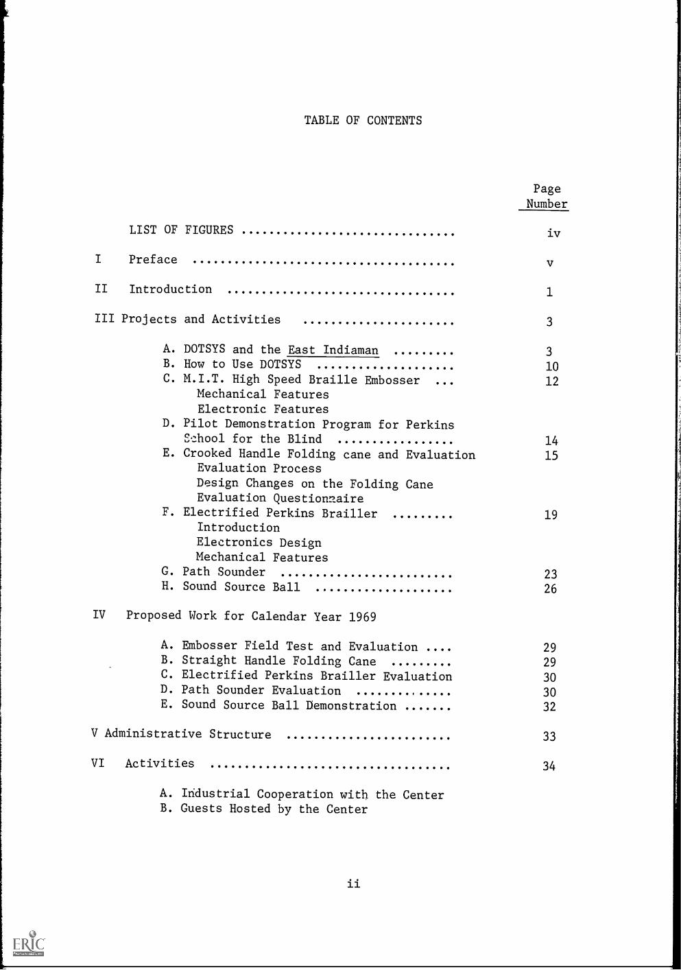
TABLE OF CONTENTS
Page
Number
LIST OF FIGURES iv
Preface
II Introduction 1
III Projects and Activities 3
A. DOTSYS and the East Indiaman 3
B. How to Use DOTSYS 10C. M.I.T. High Speed Braille Embosser 000 12
Mechanical FeaturesElectronic Features
D. Pilot Demonstration Program for PerkinsSchool for the Blind 14
E. Crooked Handle Folding cane and Evaluation 15Evaluation ProcessDesign Changes on the Folding CaneEvaluation Questionnaire
F. Electrified Perkins Brailler 19Introduction
Electronics DesignMechanical Features
G. Path Sounder 23H. Sound Source Ball 26
IV Proposed Work for Calendar Year 1969
A. Embosser Field Test and Evaluation 29B. Straight Handle Folding Cane 29
C. Electrified Perkins Brailler Evaluation 30D. Path Sounder Evaluation 30E. Sound Source Ball Demonstration 32
V Administrative Structure 33
VI Activities 34
A. Industrial Cooperation with the CenterB. Guests Hosted by the Center

PageNumber
VII Seminars, Presentations, Conferences and Publications 36
A. Seminars and Presentations 36
B. Conferences 37
C. Publications 38
VII Special Conferences 38
IX Summary 39
X Appendices 41
1. Model 3 Brailler Timing Diagram
2. Model 3 Timing Control3. Cane lengths and number of canes4. Agencies used in Crooked Handle Folding Cane
Evaluation5. Instruction for Advisors in Folding Cane
Evaluation Program6. Electrified Perkins Brailler Triac Driver
Schematic7. Sample Agenda
XI References

LIST OF FIGURES
Page
Number
M.I.T. High Speed Braille Embosser, Model 3 12
Electrified Perkins Brailler 19
Electrified Perkins Brailler, with internal electronicsvisible 22
Lindsay Russell Path Sounder, Model H 23
Pathsounder Control Panel 25
Sound Source Ball and Sound Source Ball, with internal
electronizs visible 26
iv

I. Preface
As the newly appointed director of the Center for Sensory Aids
Evaluation and Development it was my responsibility to carry on with the
traditional work established by the initial contract with Health, Education
and Welfare, Vocational Rehabilitation Administration. The work undertaken by
the Center has been documented in the previous final reports, conference pro-
ceedings, articles, papers and so forth. involvement in the area of
sensory aids in general is a long and impressive one and the Center has been
continuing in this same tradition in the specialized area of sensory aids for
the blind.
The initial phase of activities was to review the programs, commit-
ments, and obligations of the fiscal year contracts. The second task facing
the new director zwao to re-establish the-lines of communication broken by the
unfortunate death of John K. Dupress, the former managing director. After
these tasks were initiated the Center was once again on its way to fulfilling
its duties as a leader in the field of sensory aids for the blind. The achieve-
ments of the Center are noted and reviewed in this report.
The accomplishments are broad in scope and significant in meaning.
The uniqueness of the Center is that it is able to tackle and cope with a
large variety of problems and projects which require the skills of a host of
disciplines. These disciplines require the involvement of engineering, re-
search, development, evaluation, consultation, documentation, education, and
the dissemination of information.
The current activities were performed with the ible assistance of
the Center staff and through the expert help of the consultants. I am par-
ticularly indebted to the tireless assistance of Professor Robert W. Mann, of

the Mechanical Engineering Department at M.I.T., who is also chairman of the
Steering Committee. Mr. George F. Dalrymple should be commended for his loyal
participation as staff electronics engineer and helping the Center meet its
goals in a difficult year. I also extend my appreciation to the very able
administrative secretary, Mrs. Chantal Teller for her support to the Center's
activities. In conclusion the Center and its staff look forward to promising
years of activity and devoted service to the blind.
Vito A. ProsciaDirector
Introduction
The Sensory Aids Evaluation and Development Center was estab-
lished on September 1, 1964, under Contract SAM-1036-65 from the Voca-
tional Rehabilitation Administration of the Department of Health, Educa-
tion and Welfare. Members of the Staff of the Center include:
Mr. Vito A. Proscia, Director
Mr. George F. Dalrymple, Electrical Engineer
Mrs. Chantal Teller, Administrative Secretary
Mr. Norman Berube, Mechanical Technician
Mr. Alexander Glimcher, Electrical Technician
In addition to the regular staff members, the following persons
performed work on specific projects (on a part-time basis) during the
fourth contract year:
Mr. Murray Burnstine, Mechanical Engineer
Mr. Peter Duran, Mathematician'
Mr. Lindsay Russell, Electrical Engineer
Mr. Ranulf Gras, Mechanical Engineer
Mr. and Mrs. Joseph Schack, Computer Programming
Mr. John Burke, Consultant Peripatologist
Mr. William Curtis, Consultant Peripatologist
Mr. Paul Maccarrone, Layout Draftsman
Mr. Ernest Johnson, Engineering Assistant
The Steering and National Advisory Committee provide necessary
leadership and advice.

The scope of activities, as outlined in the initial contract,
is as follows:
"The Center's activities consist of the following: (1) Evalu-
ation of existing sensory aids and devices; (2) Location of new and
promising aids for evaluation; (3) To encourage others to develop new
aids which then can be submitted for production engineering at the Center;
(4) In conjunction with the above, but to a lesser degree, development
of new sensory aids for the blind; (5) Development of training principles
and techniques for blind users of the sensory aids; (6) Behavioral re-
search with blind users under field conditions; and (7) Development of
objective standards to evaluate such devices.
Basic research and development will not constitute a major
activity of the Center."
During the first contract year, the Center concentrated on
staffing, facilities, laboratory equipment, arrangements with rehabilita-
tion agencies and local manufacturers, and reliability engineering of
prototypes.
During the second and third years, emphasis was placed on
final field testing, production engineering, and negotiations with re-
habilitation facilities for applications.
During the fourth contract year emphasis was placed on the de-
velopment of the evaluation process and objective standards for the
evaluation of existing devices. In addition a significant contribution
was made in the demonstration of the feasibility of the current tech-
nology in sensory aids communication systems.
2

t
III. Projects and Activities

DOTSYS and The East Indiaman^
The Braille edition of THE EAST INDIAMAN, by Ellis K. Meacham,
(Little Brown and Co.), the first to be produced from teletypesetter
input, was published in November, 1968, only a few weeks after the ink-
print edition. The master Braille plates were produced with a minimum
of human intervention, using a series of computer programs. The pro-
cedure can be described in three parts:
1. Conversion of the TTS codes into BCD codes and the insertion of
the special format codes required for Braille.
2. Editing and correcting the BCD tape thus created.
3. Translation of the BCD tape into Grade II Braille.
Tite TTS input tape was translated to a formatted BCD tape by
a modified DOTSYS system of programs. (For a detoiled description of
1DOTSYS see 'PROCEEDINGS, BRAILLE RESEARCH AND DEVELOPMENT CONFERENCE,
NOVEMBER 18, 1966'.) The following boxes were used: INBOX, TELCON,
UNICON and UNIPER. These programs, originally written to operate on
the CTSS system at M.I.T., were modified for the 709 at the American
Printing House for the Blind. This, involved rewriting those parts of
the programs which were CTSS-dependent.
The UNICON box was rewritten and expanded to perform some of
the function formerly handled by TELCON and TELCON was thereby consider-
ably simplified. A major objective of DOTSYS is to minimize the re-
programming required to handle new forms of input and output. The UNICON
box is independe,lt of the medium which supplies its input. It is perman-
3

ent section of DOTSYS which performs the analysis and interpretation
necessary to conform to the Braille rules. TELCON is just one of a
possible set of conversion program designed to translate compositors
media into Universal code. There could be boxes written to convert
Monotype, Linofilm, etc. Each of these boxes would be independent of
the Braille conventions and would perform only that interpretation re-
quired because of the particular typesetting equipment and the conven-
tions which govern its use.
For example, the TELCON program performs a rather simple anal-
ysis to determine whether a particular letter is a capital or lower
case and passes the appropriate Universal code to the UNICON box. UNICON
performs a more complex analysis to determine whether a whole word, a
portion of a word or only the first letter is capitalized to supply the
correct BCD code.
The general flow chart on page 9a illustrates the operations,
machine and manual, which were performed in the course of producing the
Braille plates. As shown there, the six channel paper tape vihich had
been used to set the first galleys for THE EAST INDIAMAN was copied onto
magnetic tape. This step, performed in New York on an IBM 360/40 was
necessary because the APH 709 has no paper tape reading facility.
(Ironically, this operation which is technically the simplest, took an
inordinate amount of time. Both the TTS tape and APH's 200 bit-per-inch
magnetic tape are, in a sense, non-standard in terms of current tech-
nology and finding the appropriate machine configuration to accomplish
the conversion proved quite difficult.)
4

The magnetic tape containing the TTS codes sen-ed as input to
the modified DOTSYS which produced an intermediate BCD tape and a line-
numbered listing suitable for editing. A sample of this listing and of
the input from which it was created is shown on pa3es 9a-9e. This first
phase would remain essentially unchanged for producing any other book
which had been set by paper tape controlled line-casting equipment. To
publish a Braille edition from another composition medium would require
that TELCON be replaced with another box. The initial conversion step
might or might not be necessary.
Phase two, the editing phase, would remain unchanged no matter
what sort of compositors tape is used. The number of iterations through
the .editing procedure vary depending on the completeness and correctness
of the tape. In the case of EAST INDIAMAN the paper tape was used to
set the first galley proofs. From that point corrections tc, .zubsequent
galleys and page proofs were made by hand in the metal and these correc-
tions had to be detected and made on the inteYmediate BCD tape.
As shown in the flow chart, the EDIT program merges correction
cards and the intermediate tape to produce a new tape and a listing.
The first step in editing involves reading the BCD listing against copy
to locate errors. In the hope that it would simplify the proof-reading
task, a set of galleys were obtained from the publisher. Their correc-
tions which were pencilled on the margins were the first made to the in-
termediate tape. Unfortunately, the galleys at our disposal were not
those which had been run from tne tape, but had been partially corrected.
Apparently, in the course of making certain corrections, other errors
were made, leading to a rather confusing situation; there were errors
5

noted on the galleys which did not appear on the listing of the inter-
mediate tape, and errors on that listing which were no longer in the
galleys. After the first set of corrections were made the corrected
tape was proof-read against the inkprint copy of the book.
A new box, called EDIT, was added to the system to facilitate
error correction. This program reads correction cards, locates and
changes the erroneous information on the intermediate BCD tape and
writes a new tape incorporating the changes. Under console control the
new tape may be printed completely or in part. The following correction
statements are permitted:
1. LINE n: This indicates the number of the line to be changed
by one of the following statements. All the lines pre-
ceeding this one are copied from the old intermediate
tape onto the new one; then the-proper correction is
made. The line numbers are not actually stored on the
tape but are re-calculated airing each run. The number
appears on the listing for every fifth line and lines
which have been changed are flagged with asterisks.
2. CHANGE /xxx/yyy/: This causes the character string 'xxx' to be
replaced by 'yyy'. The two strings need not be equal
in length. A consistent separator character must be
used within a given CHANGE card and it must appear
three times. CHANGE may be used to delete, change,
add or rearrange characters within a line. For example:
CHANGE /teh/the/ CHANGE /tothe/to the/
6

CHANGE /thee/the/
CHANGE /th/the/
CHANGE /th e/the/
CHANGE /the//
CHANGE /he/the/
CHANGE /te/the/
The correction will be made to the first occurrence of
the lxxx' string in the line.
3. DELETE n: This will delete the nth line. Subsequent lines will
be re-numbered.
4. RETYPE xxx: The entire line indicated by the preceeding LINE
card will be replaced by the character string 'xxx'.
5. INSERT xxx: The character string 'xxx' will be inserted as a
whole line, in front of the line indicated on the pre-
ceeding LINE card.
It is interesting and gratifying to note that the proof-
reading and error-correction proceeded quiv,3fficiently, despite the
fact that the Printing House personnel involved had had no prior exper-
ience with this kind of work. Because there Qas some concern about how
quickly they would learn the techniques required, it was decided that
only two of the four Braille volumes would be edited in this fashion.
The balance of the book was corrected by key-verifying the cards which
were punched from the intermediate BCD tape. It is difficult and unfair
to compare these two procedures. However, the general impression was
that the new method worked quite well and could be expected to become
even more efficient with practice, some modifications to the EDIT box,
and, of course, cleaner input tapes.
The third phase was the translation of the corrected BCD tape
7

to Braille using the Braille Translation program which has been oper-
ating at the American Printing House for several years. Because DOTSYS
supplies the format code and special character codes usually added to
the text by the key-punch operator, this BCD tape 'looked' the same as
it would had it been produced by keypunching. Thus, the translation
phase, and the subsequent steps in the production of the book itself
were those which have become conventional at the Printing House.
This project encountered at least as many - and pro'cably more -
stumbling blocks as one would expect in any pioneering system. In
addition to the problems already indicated, the final debugging of the
new boxes (which could not be done until the magnetic input tape was
available) was performed under great pressure. Withal, we feel
that this was a successful and important 'first'. The experience thus
gained plus the progr sz. modifications outlined below will enable futtrz?
publications to proceed more rapidly and smoothly.
In order to speed and simplify the editing procedure, we pro-
pose that the EDIT program be expanded and refined. The modified box
would eliminate the need for a separate LINE card, permit making more
than one CHANGE within a given line, permit making a CHANGE to a line
which has just been INSERTed or CHANGEd, etc. In addition, the UNIPER
box which prints the intermediate BCD tape would be modified to flag
paragraph beginnings and other special format codes so that they would
be easier to locate.
Some of the errors which had to be corrected manually could be
recognized by a computer program. For this reason we propose adding a
8

new box, or more accurately a part, called PRUNE which would be a PRe-
UNicon Editor. PRUNE would be concerned with re-ordering the input stream
and correcting it so that it makes more sense,for Braille translation.
9

9 a
b 4-14-Atvel.-Ms Om. I'M
. --....,.........
()I__:nkfijLi...._
17071
u 00'00
_
-NvmeeR6i
).-4S171 CI.
.._......-
11. MM. .... .... .... Ow. 11.1.
Fe..,
-. - ..m IMP

GALLEY I.
Little, Brown, East Indiaman 85-4212 10 Electra on 12x23hf
Guide: Chapter IOnly a single captain on the 'etive list of the Naval Service of theHonourable East India Company was in England this raw Januarymorning. This was by no means remarkable, since the normaltheater of operations of the service was half a world away and itsofficers had little occasion to come to Britain except as invalids orupon retirementif they were fortunate enough to survive so.long.
The popular name of the service was the Bombay Marine, often.called with grudging admiration by officers of the Royal Navy,"The Bombay Buccaneers." The Marine was the only privatenavy in the world and was employed by the Honourable Compa-ny to protect its far-flung operations, which extended from the.Red Sea and Persian Gulf, across the Indian Ocean and thecrowded East Indian archipelago, to China. It was a service smallin numbers, but already possessed of a hundred and ninety-threeyears of honorable tradition in this year of 1806. While it sailedfrigates of as many as fifty-six guns, it was more often concernedwith ketches, snows, brigs, sloops, schooners and grabs of shoaldraft, carrying six to fourteen guns, which met and defeatedFrench, Dutch, Portuguese, Spanish, Chinese, Arab, Malay andMoro ships and forces under adverse conditions.
The officers of the Marine served not only at sea but as diplo-mats in remote areas among savage peoples; as commanders ofunits in combined operations ashore with army siege trains; asexpeditionary forces with elements of the Marinc Battalion; andas surveyors charting the eastern seas. Few sprigs of the nobility orsons of landed gentry chose the arduous service of the BombayMarine as a carecr in preference to His Majesty's Navy or Army..Some officer candidates entered as volunteers or midshipmen;others rose from the ranks if thev possessed sufficient educationand ability. Cannon and musket balls, tropical fevers, accidentand shipwreck, provided a constant attrition in the lower commis-sioned ranks and left promotion lc captain in the Service largely amatter of fortune and influence in the Court of Directors of theCompany.
This one captain in the Bombay Marine was in London for thefirst time in nine years by pure chance. He bore the somewhatpretentious name of Percival Merewether, but had risen to hisexalted rank from humble origins in life by way of the lower deck.He was a man of a little more than middle height, broad in theshoulders, not yet stooped by life below decks, and carried himselfwith the alert air of agile grace often seen in the practiced sea-man. His face, with lively blue eyes under dark brown hair, wasunremarkable except for a broken nose, badly set, a long disfigur-ing scar along his right jawline, a missing right earlobe and blue-tinged powder burns on his cheek, the combination of which gavehim an expression of ruthless determination. He had held therank of captain less than twenty-four hours, though sixteen of histwenty-eight years had been spent at sea in the service of thecompany.
Yesterday, Merewether had been a first lieutenant in the Serv-ice, junior to at least a score of other officers of vast experience,courage and ability, equally deserving of promotion to the onevacancy in the list of captains. It had been his fortune to distin-guish himself under the eyes of an Indimm's captain, who was

-90-/@@@B*W53/005K*N 25,5%LmITTLE, 1%BmROWN, 1%EmAST 1%InNDIAMAN,@10 1%EmLECTRA 10N 112X23HF33/MmARIE 13-2633/@/@%GmUIDE%. 1CmHAPTER 1133/@%00NLY A SINGLE CAPTAIN ON THE ACTIVE LIST OF THE %NmAVAL %SmE@%HmONOURABLE %EmAST %ImNDIA %CmOMPANY WAS IN %EmNGLAND THIS RA@MORNING. %TmHIS WAS BY NO MEANS REMARKABLE, SINCE THE NORMAL@THEATER OF OPERATIONS OF THE SERVICE WAS HALF A WORLD AWAY AND@0%1LICERS HAD LITTLE OCCASION TO COME TO %BoRITAIN EXCEPT AS IN@UPON RETIREMENT%80IF THEY WERE FORTUNATE ENOUGH TO SURVIVE [email protected]/@3%T1HE POPULAR NAME OF THE SERVICE WAS THE %BmOMBAY %MmARINE,@CALLED WITH GRUDGING ADMIRATION BY 0%1LICERS OF THE %RnOYAL %No@%,,TmHE %BmOMBAY %BmUCCANEERS.,, %TmHE MARINE WAS THE ONLY P@NAVY IN THE WORLD AND WAS EMPLOYED BY THE %HmONOURABLE %CmOMPA@NY TO PROTECT ITS FAR-%OmUNG OPERATIONS, WHICH EXTENDED FROM TaRmED %SmEA AND %PmERSIAN %GmULF, ACROSS THE %ImNDIAN %0LICEAN@CROWDED %EmAST UmNDIAN ARCHIPELAGO, TO %CmHINA. %ImT WAS A SE@IN NUMBERS, BUT ALREADY POSSESSED OF A HUNDRED AND NINETY-THRE@YEARS OF HONORABLE TRADITION IN THIS YEAR OF 1806. %WnHILE IT@FRIGATES OF AS MANY AS 29LIFTY-SIX GUNS, IT WAS MORE OFTEN CONC@WITH KETCHES, SNOWS, BRIGS, SLOOPS, SCHOONERS AND GRABS OF SHO@DRAFT, CARRYING SIX TO FOURTEEN GUNS, WHICH MET AND DEFEATED@%FmRENCH, %DmUTCH, %PmORTUGUESE, %SmPANISH, %CmHINESE, %AmRAB,@MORO 1SHIPS lAND 1FORCES 1UNDER 1ADVERSE 1CONDITIONS.33/@3%TmHE 0%10CEPS OF THE MARINE SEI'VED NOT ONLY AT SEA BUT AS@MATS IN REMOTE AREAS AMONG SAVAGE PEOPLES. AS COMMANDERS OF@UNITS IN COMBINED OPERATIONS ASHORE, WITH ARMY SIEGE TRAINS. A@EXPEDITIONARY FORCES WITH ELEMENTS OF THE MARINE %BnATTALIOK@AL SURVEYORS CHARTING THE EASTERN SEAS. %FmEW SPRIGS OF THE NC@SONS OF LANDED GENTRY CHOSE THE ARDUOUS SERVICE OF THE %BmOMBtMmARINE AS A CAREER IN PREFERENCE TO %HmIS 5MrAJESTY,S %NmAVYaSmOME OULICER CANDIDATES ENTERED AS VOLUNTEERS OR MIDSHIPMEN.@OTHERS ROSE FROM THE RANKS IF THEY POSSESSED SU%1LICIENT EDUCA1@AND ABILITY. %CmANNON AND MUSKET BALLS, TROPICAL FEVERS, ACCIC@AND SHIPWRECK, PROVIDED A CONSTANT ATTRITION IN THE LOWER CO*@SIONED RANKS AND LEFT PROMOTION TO CAPTAIN IN THE %SmERVICE LI@MATTER OF FORTUNE AND IN%OmUENCE IN THE %CmOURT OF %DnIRECTOR@%CmOMPANY.33/@3%T1iHIS ONE CAPTAIN IN THE %BmOMBAY MARINE WAS IN% LmONDON F@%9mRST TIME IN NINE YEARS BY PURE CHANCE. %HmE BORE THE SOMEWF@PRETENTIOUS NAME OF %PmERCIVAL MEREWETHER, BUT HAD RISEN TO@EXALTED RANK FROM HUMBLE ORIGINS IN LIFE BY WAY OF THE LOWER (
@%HmE WAS A MAN OF A mLITTLE MORE THAN MIDDLE HEIG:IT, BROAD IN@SHOULDERS, NOT YET STOOPED BY LIFE BELOW DECKS, AND CARRIED H:@WITH THE ALERT AIR OF AGILE GRACE OFTEN SEEN IN THE PRACTICED@%HmIS FACE, WITH LIVELY BLUE EYES UNDER DARK BROWN HAIR, WAS l
@MARKABLE EXCEPT FOR A BROKEN NOSE, BADLY SET, A LONG DIS%9LIGUF@SCAR ALONG HIS RIGHT JAWLINE, A MISSING RIGHT EARLOBE AND BLUI@TINGED POWDER BURNS ON HIS CHEEK, THE COMBINATION OF WHICH GA@HIM AN EXPRESSION OF RUTHLESS DETERMINATION. %HmE HAD HELD THI@RANK OF CAPTAIN LESS THAN TWENTY-FOUR HOURS, THOUGH SIXTEEN Of@TWENTY-EIGHT YEARS HAD BEEN SPENT AT SEA IN THE SERVICE OF [email protected]/@3%YmESTERDAY, %MmEREWETHER HAD BEEN A %9mRST LIEUTENANT IN THI@ICE, JUNIOR TO AT LEAST A SCORE OF OTHER 0%1LICERS OF VAST EXPI

9c1 -360808081325192129360303211E2506040404392126211B091F000101091026C
04201B0C1F06120C180718062604202C21322A3937393434360MW2D04201B130051634343602081B071F180A0C100420303239353434360201i36p2081B0h1F1373434360204B031F060915041804140C060B0910040E180001180C06040306C1604010510041B061F180F1809041B141F100A0FOCOE10040316040105100208101041B0C1F06120C18041B0E1F03070D18061504191814040C06U41B101F060BC061C180A15020807030A060C060B27041B011F050C1404191814041315040603C041400060E10040105100406030407180902080105101801100A040316040301)]0A0FOCOE1004191814040518091604180419030A091204181918150418061204(090C0101091004030E0E18140C0306040103040E030710040103041B131F0A0a18090C121404030AD208)1CODO306040A1001000A10071006011B2C1F0C160401(041006031C0B0504010304141C0A0FOCOF100414002250903060B273434376US
1-
0710040316040105100414100A0FOCOE100419181404010510041B131F030713]02080E180909101204190C0105040BOA/C120B0C060B041812070C0A18010CO3(0510041B0A1F03151809041B061F180F152602081B2222011E0510041B131FOR2222041B011F0510041B071F180A0C0610041918140401051C0403060915040D(100419030A091204180612041918140410070D09031510120413150401051004)0D181F3202080615040103040D0A0301100E01040C011404161804 321B2D1F1C(0E0504101701100612101204160403070401051002081BOA1F1012041B141F1031F1C09162604180E0A03141404010510041B0C1F06120C1806041B031F0E1C18(041B101F181401041B0C1F06120C18060418040E050C0D100918030326040103(0418041410040FOCOE1004140718090902080C0604061C07131C04 142604131C(12040316041804051C06120A10120418061204060C061001153201050A101002(1004010A18120C010C0306040C060401050C14041510180A04031604372C2D35;
12020816040C0B180110140403160418140407180615041814041B231F160115:07030A10040316011006040E03060E100A0610120208190C0105041E10010E05140903030D142604140E05030306100A1404180612040B0A1813140403160414(0C060B04140C170401030416031C0A01101006040B1C0614260419050C0E0504(1B1O1F0A10060E0526041B121F1C010E0526041BOD1F00011COB1C10141026(1C141026041B181F04 181326041B071F180918350418061202081B071F030403(101404201C06121004042018120F100A141004200E0306120C010C0306142734:1404031604010510041B071F1804 00061004141004 0F10120406030104030609OD09031F32020807180114040C06040A100703011004180A101814041807030611814040E03070718061240041404031602081C060C0114040C06040E0307130C10304 102604190C0105041804071504140C100B10040104180C06142B0418140210E101404190C010504100910071006011404031604010510041B071F1804 0006
0208181404141C040F1015030414040E051804010C060B0401051004101814010A0C0B1404031604010510040603130C09,)C011504030A020814030614040316(14100401051004180A121C031C140414100A0FOCOE1004031604010510041B13140418040E180A10100A040C06040D0A1016100A1C060E1C040103041B051FOC0F1504030041B181F0407152702081B141F03071004031B371F0E1004040E18.14040F03091C060110100A1404030A04070C121405000D0710062B02080301050A18061E14040C160401051015040D031414101414101204141C1B371F0E0C1018130C090C011527041B0E1F18060603060418061204071C141E100104131809142604180E0E0C1210060102081806120414050C0190A100E1E26040D0A030F010A0C010C0306040C060401051004090319100A040E0307070C141F320208141601040D0A030703010C0306040103040E180D01180C06040C0604010510041B020807180101100A0403160416030A011C061004180612040C061B2D1F1C1006
0316041B121FOCOA100E01030A140403160401051002081B0E1F030701806150E180D01180C06040C060401051C041B131F0307131815041B071F180A0C0610030A0401051002081B231F0A140104010C0710040C0604060C0610041510180A1B051F100413030A1004010510041403071C1905180102080D0A10011006010COCOF1809041B071F100A1019100105100A2604131C0104051812040A0C14100618061E041604030704051C071309100403040C0B0C0614040C0604090C161C040A0412100E1E2702081B051F10041918140418040718060403160418041F090C1209100405100C0B05012604130A031812040C060401C51002081405031C0912101204131504090C16100413100903190412100E1E142604180612040E180A0A

s
T.FL I1 2X.2::.11F $i L =vAR I,. 3-26 1::1
=c1,AP1H-', 1 1.i.L =1.LY A r:.I;a;L, (APTAIN 71d A(TIV LU.T
=N4VAL =1-10\WPAPLE =FAST =I:".)14 =COMPANY t.
=.GLAN'..) Thr- =JANUAkY =IHIS ,:111 NO N'EAN:.
SINC. THc NOIL Tt-IATER OF uPtP,',110Ni; OF 'EH,:
HAD= A ;.*:UNLL,1 PM; r1;d: LiITLt C;CC;A:1:1%
COW- 10 =P,NITAAN LXCtPT A() INVALIDS 0:: uPCM
FORTuNATc: FNOI.Y,-)H Tr.; SUF,VIWL SO LO!%W. ;I:FL SPAk =THE P(
NP.:..T OF TW. THL =;1,0MBAY =N1ARINE, OFTEN CALLF:
(IRL.nc7I IO D OFF 1(P Of- TH' !CYL flAVY, =(=Jf
=PUCCANFF.R::..=) =tHL =',1ARINE wAS TH: Of'iLY PRIVATF ;
TAE VORC". AV, '::As THF
FARFLUNG OPERATIONS, ::HICH Thf:". =RE!) =Si
=r..!JLF, ACROS Thf =0(:1?% T-fr c,Rom,-:!;
=INDIAN ARCHIPFLA(7;0, TO =CHINA. =IT VAS 4 Si4ALL U
7UT ;ILD,FV.:Y Pcc;nEFD OF A 1-4Uts.i--:P NINTYP-J!
YEARS OF HONORA:AF 71.-or1 1 icN IN THIr... ().;- 1806. =v/HILE
SAILED ;'Prii%TFS lANY I) VOkE
-02 CCNCERNiO AC;Pr, 5CHOGNER
OF SHOAL PIU;FT, ctRPYIr:(1 SIX TO FO)RT!:Fil CUW:, HIC VrT /
nEFFATFn =PRNr1-1, =r)UTCH, =PORTUGu, =CHINFSE
=vALAY =:'ORn FrRCI.S X,IrNr:P :.rVrR!F Cr)NITION:
SPAR =THY, TAF =1\/.1 W NCYT OLY iT s;:A. !
r'IP.L0'4ATc. I" .7- VInt°.0 r'""T'Lr5=,
UNIT IN (0%,.1 ODLN/410: AIT bPYY
rXpflITIOw.:*RY 4:ITH ::1_77:%1ETS F T:;,"
AND AS 5A:RVF.Y0S CHAPIING 1-4,ST,IRN =FF*1 !,:PRIr.:7!: 01
%%)!A;T(; =HP)
=1,1LVY
vI)SHIpzY=, 1:No;. THL: Ii-. THY DC;.55E)A-ILITY. cALL
TROPICAL FrVEI-?S, =Nh PKVID:=1) A (-T
ATTRITIr"v T-1:DP.7:0T
r/IPTAIN Im 1.:LY A YATT=!: ("):: I
Ir THF =CoUkT =:1.n.CTOR7, THE =C(,)=A,%Y. =Tr
CP-PTA1N IM TH= =viti-;17 +..AS IN =:CN1%0N TH:: PIK.
IN MINE Y:7AS P;P:. CH:\NCL. PRFT;:
:..;,4 NAVE OF =PPCIVAL HAt N I P.)
FROM LIFt ';:AY OF IHC =H:
MAN OF A LITIL' THAN hLIr.:r1T, rk0A", IN TH.-
NOT YET sT:)OPE:). Y
bLFRT AIR f)i- r-RACF OL'T't F.J"-.N: IN T:-' PRACTI(7.-r7n
FACE, LIW-LY 'A HAIk,
mNRPWRKAnLF rXr:DT 7:01: A :ROKFN tc.cr , PArILY A LO
:1_0.\!u JL:A_I:vr, A "ISSIN6
L:!RN!,. r;N h1 17.:4
YHICH AN 'XPkt..c:10.4 OF kUfl-LC.S r
";'5' HELD THi- PINK =')f-THAI\ TVI,NIYE0 HooRs,
SIXTEi-N OF :-.P) 't'LARS :-.P:NT AT .-/LA I
cERVICE CF Tr :.:1.1PNY.
LP:',:ILT IN Ir17: IU LEAsT A
OTH;:R OFFII..1 1/;)1 1-XPLkI-%CF, ((;tsk; ALILITY,
flFc,Ff-VINC. (,TION \I^.CA!0(Nr LIST OF
CAPTAINS. =11 -1Ai, FONTMFPic rYFr. o- '=" "C-0
C;F LAK(74-
yL 117 OF
,! 6 =vtrF"Fri-ir,...FUSION F TI-
=t)IPF-,T^RS =IN:IA
IN =LEA1)t-NLL :-....1JECf TO INCTLRVP.,% IF
=COURT (-0 1.2)E:,PE1.), IN FULLDRF.SS JNIFOR%r",.11 0.1,e( 7, r r.' 1 ! I r1L, e. i

How to Use DOTSYS
HOOK is the program which is concerned with configuring the system
for a particular purpose. For example, to print typewritten dots on a
terminal from typed input it is necessary to use TYPEIN, BRAILL and DOTPR.
This information would be furnished to HOOK.
HOOK creates the linkages betwlen boxes by placing the appropriate
XEC OUTER instruction in the input terminal of each box. HOOK also
calls the reset routine, if any, of each box, and then transfers control
to the final or output box, which then starts the processing.
In order to accomplish HOOK's function each box must provide an
ENTRY card and a table of contents as follows:
ENTRY Name of box (e.B. UNICON)
INTER CLS =0OUTER TSX MYSELF,4UNICON TRA RESET or TRA 1,4 if resetting is
not necessary
The table of contents may be located anywhere in the program, while
the ENTRY card, of course, must be one of the first cards of the program.
The TSX instruction of the OUTER (OUter TERminal) must transfer to
a location within the box which saves the address in index register 4
in order to return correctly when the box has completed processing and
has information to output. Because the calling box has performed an
10

XEC the proper return location is placed in index register 4 by OUTER's
TSX.
HOOK requires a list of programs to be reset and linked to-
gether. This is furnished by modifying a card in the HOOK FAP deck and
reassembling. The card is labeled HOOK and a sample follows:
HOOK RESET (OUTBOX,FORMAT,BRAILLUNICON,TELCON,INBOX)
RESET is a macro which generates a list of TSXs to the in-
struction which transfers to the reset routines. Each RESET must end
with a TRA 1,4. After resetting HOOK then creates the XEC instructions
using the information in the transfer vector created by assembly. Execu-
tion of a particular configuration is accomplished by loading HOOK and
the desired boxes and then transferring control to HOOK.
Please note the details of the HOOK card. The label must be
HOOK, the op code must be RESET. The box names are separated by commas
and enclosed within parentheses. There must be at least two boxes.
One final note on configuration which requires the use of the
BRAILL box. At load time BRAILL must be loaded followed directly by
SMALLT and TABLE i.e. LOAD BRAILL SMALLT TABLE HOOK UNICON INBOX etc.
This is necessary because the TABLE is referenced by its distance from
the last location in BRAILL.
This document is intended to read in conjunction with the des-
cription of DOTSYS given in the Proceedings of the Braille Research and
Development Conference2dated 18 November 1966 and sponsored by the
Sensory Aids Evaluation and Development Center, M.I.T.
11

M.I.T. High Speed Braille Embosser
Mechanical Features
A high speed braille embossing system has been under development
at the SAEDC and the Mechanical Engineering Department at M.I.T. since
1960. A detailed historical account including the disposition of assembled
units can be found in our previous documents. A grant from the Hartford
Foundation running through June 1970 is providing support for the program.
Since 1967 the SAEDC has utilized design,drafting and shop facilities
of the M.I.T. Instrumentation Laboratory.
Out of this cooperative effort has evolved a much improved
machine known as the IL or Model 3 Brailler. While the cost of some
fabricated components has gone up, others have been replaced by parts
which are now commercially available. Only the major design changes not
previously reported are listed below.
1. The crank-shaft cycle clutch has been replaced by a clutch-brake.
To date we have tested these units to 6 million emboss cycles without
failure.
2. The friction roller paper drive has been replaced by a paper
tractor/digimotor drive.
3. The cam driven escapement has been replaced by a continuously
driven 1/2 revolution gear set.
4. The escapement rack is displaced horizontally instead of ver-
tically.
5. The embossing heads are located by a set of "V" ways instead of

M.I.T. High Speed Braille Embosser, Model 3

flat ways.
6. Ducting has been utilized to direct cooling air where required.
Electronic Features
The Mark 2 Electronics for the Model 3 has four modes of
operation: Manual, Tape Reader, EQIDOT Exerciser, and BIDOT Exerciser.
The manual mode permits embossing single or multiple dot cells by switches
on the control panel. In the tape reader mode, a Friden SP-2 tape reader
controls th, :Jibosser. The EQIDOT Exerciser produces a braille pattern
that has all possible cell combinations (except space). This pattern is
generated by a "Maximal Length" Shift Register. An option for Carriage
Return after "for" is available. The BIDOT Exerciser has most of the
test features described for the exerciser in the 1965 Final Report.
The electronics are constructed using Digital Equipment Co.
R- and W- series computer modules. Several logic functions have been
changed in conjunction with mechanical changes. The Carriage Return func-
tion is now performed by spacing to the end of the line. Previously it
was performed by holding the rack down with a solenoid and letting the
heads move freely until a head struck the "false tooth" on the rack.
The timing of the automatic Line Feed has been changed. In
the earlier design the Line Feed was started by the head closing the
start line switch. In the Model 3 the time of the automatic Line Feed
is determined by a delay in the electronics. This delay is initiated
by the pulse that triggers the cycle-clutch. The delay is the time it
takes the platen to emboss and clear the pins. The circuit is enabled
13

'by a head in the last cell holding the end-of-line switch closed.
The embosser has operated for short periods of time at 16 cells
per second embossing from punched paper tape. Most of the embossing per-
formed to date with the Model 3 has been at 16 cells per second using
the exerciser modes, both EQIDOT and BIDOT.
Pilot Demonstration Program for Perkins School for the Blind
A test brailler, with most, but not all features of the
Model 3 brailler was used to emboss 800 sheets (25 copies of 32 pages)
of braille from punched paper tape. The input tape was prepared at
Howe Press of Perkins School for the Blind using equipment developed
at the American Printing House for the Blind. The material was part of
a pamphlet on the American Revolution. Fifteen copies were given to
high school history students at the Perkins School for the Blind. Only
11 errors could not be attributed to errors in the tape and brailler
operation. This is one random error per 43.6 pages or 24 errors per
million cells.
The purpose of the program was to demonstrate a possible applica-
tion for limited copy braille duplication. The normal process of braille
duplication requires the preparation and use of embossing plates to produce
braille. However this demonstration showed that a single punched paper tape
could be used to produce several copies or limited multiple copy ruus of the
required literary material, thereby substituting one paper tape for many
zinc embossing plates. The pilot program also demonstrated the use for a
14

device which fills the gap between the large run braille printing system
and the hand-copy braille production method. An added advantage shown
by this pilot study is that the vehicle used for production, punched
paper tape instead of zinc plates, is more easily stored in the case of
the M.I.T. high speed braille embosser.
Crooked Handle Folding Cane and Evaluation
Since its founding in 1964 the M.I.T, SAEDC has been pursuing
a development of folding canes. The learning process has been a long
and tedious one, past reports have indicated and have been documented as
to the effort and emphasis that has been placed in the evaluation and
development of existing folding canes. Studies included testing of
commercially available canes which are distributed and sold to the blind
for mobility purposes. However, these canes do not meet with the rigid
requirements specified by the M.I.T. studies in the area of .Rolding canes
as specified as early as the Final Report for fiscal year 1965-1966 for
M.I.T. SAEDC, The requirements laid down by the Center state that the
folding cane must be portable, light weight, durable, rigid when ex-
tended, balanced, economical and must have a life time of at least a
year. The Center feels that the swaged tube central steel cable folding
cane presently meets many of these specificati.ons,
During the conference for mobility trainers and technologists3
the Center was urged by the attendees to distribute the presellt config-
15
uration of the swaged tube central steel cable crooked handle folding
cane for evaluation purposes to appropriate agencies and participants.
Shortly after the conference the project was undertaken at the Genter
to manufacture and distribute 100 folding canes to interested evaluators.
Chart I, Appendix 4, contains a list of the agencies that took part in
this evaluation program and includes the number of folding canes dis-
tributed to each agency and also to a number of individuals.
Evaluation Process
A folding cane evaluation and distribution program was initiated
at the Center early in 1968. The following steps were taken in order to
insure distribution and evaluation of the folding cane: 1) drawings ware
prepared aad sent out to vendors to bid on the manufacture of cane sections;
2) the cane parts were manufactured and returned to the Center, to be
assembled into various length canes; 3) the participating agencies and
individuals specified length of canes required for the subjects and also
tips, see Chart II; 4) a cane package uas assembled which included descrip-
tive material, instructional material and questionnaires (Final Report,
1965-1966) for evaluation purposes; 5) cartons and packing materials were
purchased for mailing purposes; 6) a maintenance facility was established
at the Center for damaged or broken cares.
The procedure used in the evaluation conzzists of several steps:
1) A subject and a sighted advisor are selected. The subject
must be an experienced cane traveler.
2) The cane is made to order for the subject, with lengths re-
16

stricted to even-numbered inches: 48, 50, 52 etc., with the choice
of tips: the AFB glide tip or the nylon tip similar to the one used
on the Veterans Administration Cane.
3) The sighted advisor following the illustrated instructions
teaches the subject the correct techniques in folding and extending the
cane.
4) The Legal Release, General Information Form, and a Pre-
Test Questionnaire are filled out.
5) The subject uses the cane in his normal activities for
approximately 2 months.
6) Broken or damaged canes are returned within a day after
they are received.
7) After this period the Post-Test Questionnaire is filled
out to record the subjeces response to, and his opinion of, the cane.
8) The cane is left with the subject as long as he submits
periodic informal reports of his use of the cane to SAEDC.
The technical custody remains with the Sensory Aids Center.
Canes that are not being actively used are recalled. The recalled ones
have been reissued to additional subjects.
Desi.gn Changes on the Folding Cane
All canes returned to the Center were examined by design
personnel before the canes were repaired. In many instances, wear marks
not related to the more obvious defects indicated the user was not
17

properly instructed in the assembly and disassembly of the cane. Several
returned canes were damaged by abuses which no design could eliminate,
i.e. "run over by automobile", "bashed against steps by naughty child",
etc. Based on field failures the following changes were made.
The Center purchased a better designed ferrule crimping tool
to secure the loops at either end of the central steel cable. The new
tool features dies that cannot be closed beyond the optimum distance
required for maximum cable strength.
The roll pin cable attachment design at the lower cane section
has been replaced by a tapered aluminum plug. The described design
change improves cane balance, facilitates cane assembly and improves the
exterior appearance of the cane.
Evaluation Questionnaires
The actual evaluation process is being conducted through the
use of two forms: the Pre-Test Questionnaire, and the Post-Test Ques-
tionnaire. The first is answered by the subject before he is given the
SAEDC folding cane and it is meant to determine his attitudes and opinions
towards canes he has used in the past and toward cane travel in general.
The main questions about past canes concern: durability, the material
of which the canes were maat,the material of which the tips were made,
the piesence or absence of reflectorized coating, compactness of the
canes and whether they were folding or rigid. And finally a series of
questions ask how the subject feels about the cane as a sign to others
that he is blind. After completing this questionnaire the subject is
18

given a crooked handle folding cane, instructed in its use and asked to
use it for a two month evaluation period. At this time the subject is
asked to fill out the Post-Tert Questionnaire. This questionnaire has
as its main purpose to determine the attitudes and opinions of the sub-
ject on the cane independently and relative to his past canes. The
questions about the folding cane concern: its rigidity, balance, ease
of Issembly and disassembly, compactness, durability, comfort of the
grip, capacity to relay information along the shaft and comparative
weight. Again the subject is asked how he feels about the cane as a
sign to others that he is blind and whether the folding cane has made
any difference to his feelings.
All the questionnaires have not yet been returned, so the re-
sults of the evaluation will only be available in calendar year 1969.
Electrified Perkins Brailler
Introduction
Many atcempts have been made to electrically assist the manual
effort input to the Perkins Brailler. However no attempts have been
made to manufacture a Perkins Brailler which would incorporate an
electrical assist feature. This document will not attempt to explain
the whys and wherefores of the other efforts or to attempt explanation
of any philosophy or technological features of other systems. Instead
a description will be devoted to a program which the Center has undertaken
19
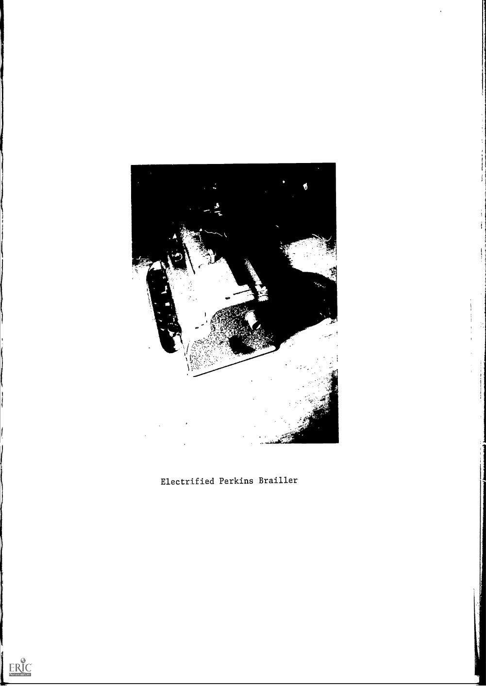
Electrified Perkins Brailler
and which is considered to be a straightforward solution to the elec-
trification of a Perkins Brailler.
The Center initially attacked the problem of the electrifica-
tion of the brailler by building a large electronic test package to
pulse a solenoid which would drive a rack and platen. (This system was
described in the 1966-1967 Final Report.) (The solenoid was selected
and installed by Howe Press of Perkins School for the Blind.) Even
though excellent braille was produced by this electronic test package
it was evident that the size of the test module was too large for
practical purposes. In mid 1968 a further development proceeded along
the lines to design a small alectronic package which would be housed in
a carrying case and which could easily be connected via a cable to the
brailler. However the two unit approach is undesirable since it would
involve carrying two packages, an electronics pack and a braille writer.
This approach became no longer necessary since electronic state of the
art made new components available. An ensuing development was undertaken
to bread board a final design which would then be incorporated in the
brailler frame. Special attention was also given to hardening of strate-
gic parts, which would otherwise be weakened by excessive forces applied
to the machine; improving linkages betwee' rack and solenoid; selection
of a solenoid different from that proposed by Howe Press of Perkins
School for the Blind; and mounting of the apprOVTradrewitches.
The basic design concept envisioned in this program was to
maintain as many of the original design features of the machine as was
possible. The design features which were established required that:
20

1) an electrical assist would be applied to replace the manual embossing
effort; 2) the functions for the line-feed, back-space, and carriage
return would remain as in the original brailler; 3) the electronics used
would be self-contained in the machine; 4) the original carrying case
would be used to store the machine; 5) some technique for controlling
the electronics would be incorporated to help overcome some of the
noise produced by applying excessive forces during embossing; 6) relia-
bility and maintainability would be essential design features; 7) safety
is a prime consideration; 8) a low cost brailler was considered to be
the final goal.
The design parameters set forth in the above specifications
have been realized in a limited run production of ten Perkins Electri-
fied Braillers which will be made available for distribution and evalu-
ation in fiscal 1969. The acceptability and utility of these machines
will be tested by a select group of individuals covering a cross-section
of braille activities and disciplines. The group will consist of students,
professional workers and volunteer braillists. It is anticipated that
this evaluation program will run for a period of one year in order that
a large sampling of the blind and volunteer braillist population may
be tested.
At the Ramada Inn conference of May 1967 complaints were
voiced concerning the excessive noise produced by the snap action of the
solenoid. Due to the variation in the tolerances of the components
(electrical, mechanical and brailler production) it was difficult to make
identical operating units. Therefore an external adjastment knob was
21

J
, ,t I
k40 4 44,1-10
A .4 I?. I " 41"
f
)21
e
Electrified Perkins Brailler, with internal electronics visible

mounted to the end-plate of the brailler in order to compensate for the
differences incurred in component variation. A secondary effect of the
presence of the adjustment circuitry was to create a trade-off between
noise created by solenoid action and acceptable braille display. Further
attempts will be made to investigate other noise limiting substances or
methods which may make the brailler even more attractive.
Electronics Deskin
The electronics uses a "Triac" as the switch. This is a bi-
directional solid state device that conducts when it is triggered by a
low level control pulse and turns off at the next reversal of the line
voltage. A "one-shot" and gate is used to generate the trigger pulses
from a fill-wave rectified signal. This provides the correct timing
for the Triac trigger pulse. To supply sufficient energy to emboss the
brailler requires one full cycle; therefore the triac must be triggered
twice.
A series rheostat in the solenoid circuit to control the peak
current and thereby the force is used to set the force level to the
lowest usable point. The different grades of braille paper require
varying amounts of force to emboss. By operating at the lowest reason-
able force level both the wear and the noise level of the brailler can
be minimized.
A "one-shot" is used to provide a 7 ms delay between the space
bar switch closure and energizing the solenoid. This compensates for
the time variation of key depression by the braillist. The embossing
22

action takes less than 16 ms and all embossing pins must be locked by
the cams before the solenoid is energized.
Mechanical Features
SAEDC personnel have assisted the manufacturer of the Perkins
Bra-111er (Howe Press) in advancing their design concept of a solenoid
assist to reduce the manual effort required at the keyboard. The Center's
participation has been confined to the areas of design, preparation of
engineering drawings, fabrication of electronic modules, and evaluation
of assembled units. All mechanical assembly and adjustment operations
were handled by Howe Press personnel. In general the design changes
accomplished since last reported provided for mounting and actuator
linkage and certain frame modifications necessary to mount the circuit
boards within the existing brail1er envelope.
The initial advantages of the solenoid assisted platen design
(economy and simplicity) are trade offs for the high accelerations, snap
action, and noise characteristic of solenoids. We do not plan to under-
take a noise reduction program for the described machine until its
durability has been demonstrated by actual use in the field.
Pathsounder
Reference is made to earlier annual reports for a detailed
23

Lindsay Russell Path Sounder, Model H

description of the Pathsounder, a small, chest-mounted sonar designed as
a supplementary travel aid for cane users. It was noted in the imme-
diately previous report that in the year coming up some further design
refinement was to be made on the instrument and that the project had
reached a stage wherein closer ties ought to be established with the
cane traveling community. These objectives have been accomplished during
the past year, with fairly encouraging results.
Two instructors of mobility,graduates'of the Boston College
program in that field, were retained by the Center as consultants, part-
,V
time. Between them they trained three blind cane travelers in the use
of the Pathsounder, using redesigned instruments that became available
in the summer of 1968. A photograph of one of the instruments is
shown in the figure. This training project added substantially to the
total experience with the "man-machine interface", au aspect obviously
of dominant importance in this program.
The end of autumn brought to four the number of cane users
who have received formal Pathsounder instructions. Of these, one has
left the country and another, whose progress was impeded by a number of
technical problems, was not interested in continuing with the aid.
The third, a college sophomore, has retained the instrument he
trained with and is using it regularly in commuting from a suburban home
to a city college via public transportation. Re is one of the most
skilled users, and has many times co-operated with the Center staff by
navigating through shopping crowds, trailed by his instructor in the
company of teachers-in-training, visiting mobility workers, etc.
24

The fourth trainee, a high school student just turned sixteen,
is finishing his lesson program - both cane and Pathsounder - and is
probably the closest of the four to being describable as an "enthusiast".
Significantly, perhaps, his training with the aid began along with his
general travel lessons, in contrast to the others, who were fairly ek, r-
ienced travelers with well-developed habits before being introduced to
the Pathsounder. He sought permission to retain the instrument for use
on his own, rather than just at lesson time, and is reportee by his in-
structor to be using it very regularly in his home town for shopping
trips, recreational travel, etc.
It has become apparent that instruments should be available
for retention by some students after their lesson program is completed,
and so five more have been ordered. The object is not to give the Center
the role of distribution agency, hut rather to make possible the study
of Pathsounder users with a lot of experience, a most important part of
the evaluation effort.
Description of the Pathsounder
*Jr
f
Remote Audio Jack
41
Loudness Switch
41 40 Z4 11:77
25
-"Charging Jack
On-Off Switch
Ramp Switch

The sketch shows the control panel of the H model sounder. The
ON-OFF switch turns the sounder on when pushed forward (away from the
user's chest). The 'RAMP switch affects the loudness of outer-zone
sounds. It is normally pushed forward in a noisy location. The LOUD-
SOFT switch controls the volume of all display sounds, and the forward
position is for loud. An effort has been made on these units to have
all switches function such that "Forward is Safest". Safest means that
the unit is on, volume loudest, greatest range in the case of special
switches installed to alter range limits, etc. The charging jack allows
the sounder to accumulate power for approximately 8 hours use from a
separate charger pack. The remote-audio jack is provided for special
projects: feeding the display sounds to a tape recorder, radio data-
link, special speaker or headset, etc.
Sound Source Ball
During the spring of 1968, a Sound Source Ball was loaned to
a Physical Education teacher, Michael Cataruzolo, at Perkins School for
the Blind, for student use, primarily in the elementary school Physical
Education program. The ball was essentially the latest design of the
Woodie Flowers Sound Source Ball (70249-3)4except for the use of a punch-
ing bag bladder. Since that time round bladders have been obtained.
While at Perkins the ball was used for several different types of games,
both indoors and outdoors.
26

Sound Source Ball
,
Sound Source Ball, with internal electronics visible

One of the games was baseball as played by the lower school
boys. They played in a paved court, normally used for roller skating.
In their usual game, a soccer ball is bounced to the batter who swings
with his arms. The bounce helps the batter to locate the ball. With
the Sound Source Ball it was possible to eliminate the bounce and the
ball was pitched directly to the batter. Most students could catch
the ball, some on the fly. The sound source ball added greater flex-
ibility to the game and increased the students' enjoyment of the game.
The same group of boys used the ball for soccer, which was
played on a grass field. The students with the better mobility capa-
bility could run up to the ball and kick it on the run. Most of the
others could locate the ball, but could not kick it with a high degree
of certainty. One student -- a very poor traveler -- could not even
locate it.
The ball was also used by this group of boys in basketball.
Again there was the wide variety of performande of the students, but the
indoor environment added a new problem, sound reflections from the walls.
In the new gym, approximately regulation size, the performance of each
boy was worse than in the older gym or outside. This difficulty apparently
was caused by reflections from the hard walls of the new gym. These
walls are of heavy wooden doors or solid masonry. The old gym is smaller
but mats hung along parts of the length of the long walls do much towards
deadening the room. A metronome is mounted just behind the backboard
and slightly above the basket as a basket locator. The wall and floor
reflections have less effect on the basket locator than on the sound
27

source ball because the short slaration of the metronome pulse, the
fixed geometry of the metronome in the room, and the experience of the
players with the metronome all reduced the effects of the reflections.
The high school boys also uses the ball in their baseball
games. In this game a softball bat is used by the batter. During one
of these games, the ball was batted into a tree, where it became caught
on a snag. This ripped the cover and punctured the bladder. Before
this accident the ball survived 3 weeks of heavy usage without diffi-
culty.
Mounting the electronics via shaped rubber pads on the skin
appears the optimum method of those investigated previously. These pads
affect the rebound or bouncing characteristics only slightly. A student
can dribble the ball with no difficulty, but on long bounce passes the
ball does not always bounce true. The dynamic balance of the ball is
sufficient for the ball to be passed or thrown on a line without notice-
able deviaLion.
The skin and bladder of the ball require further developmcut.
They must be transparent to sound, resistant to abrasion, and puncture
proof. Since the last criterion is not met the present design is
serviceable only in environments selected such that there are no sharp
objects, twigs, thorns, small stones, etc. But this brief exposure to
students demonstrated that the ball has a definite place in the blind
students physical education and play programs, even in its present
state of development.
28

IV. Proposed Work for Calendar Year 1969

Embosser Field Test and Evaluation
The use of the time-shared computer as the means of providing
instantaneous braille translation from keyboard input at remote braille
consoles has been demonstrated a number of times at the Center. The
Center proposes to expand the demonstration of this capability and thereby
explore the economic and operational aspects of extended applications
of the system. We plan to investigate the installation of several braille
terminals to be located in selected public or private schools in the
Boston area as well as in selected industrial locations where the effect-
iveness of already employed blind persons would be enhanced by access
to immediate braille. Several terminals simultaneously operational
over a select time-period will be used to gather detailed information on
the use and cost of such a system as well as deriving peripheral bene-
fits from the evaluation, reliability and accuracy testing of both the
brailler machines and the computer translation program.
Straight Handle Folding Cane
Cane users and peripatologists have urged the development of
a straight-handle folding cane. Subsequently a prototype model was
designed and assembled by SAEDC personnel. It is therefore proposed
that a straight-handle folding cane be developed and distributed for
comparative evaluation according to the guidelines escablished for the
crooked-handle folding cane. [Note: see the section on crooked-handle
29

folding canes.]
The program will distribute canes to agencies and subjects,
with the qualification that the latter will be experienced with folding
and rigid cane mobility techniques. In addition to the assembling and
distribution of the straight-handle folding cane to a select group of
evaluators it is proposed that a revised questionnaire be developed for
this program which will be specifically tailored to collect data on the
usefulness, acceptability, desirability and appropriateness of the
straight-handle folding cane.
Electrified Perkins Brailler
Plans have been made to manufacture and distribute a limited
number of electrified Perkins braillers for evaluation purposes. [Note:
The brailler has been described in section III] The evaluation process
will include the preparation of a questionnaire to be distributed with
each brailler. Subjects will be selected from volunteer braillist groups,
blind professionals and students. The evaluation period for this program
will extend for approximately one year, during which time each participant
will be required to operate the machine for a period of about two months.
Lindsay Russell Pathsounder
The Center has in its possession several monaural "pathsounders",
30

ultrasonic mobility devices designed as supplementary aids for cane
travelers. The pathsounder travel technique is in an experimental
stage, and the Center's role has been that of teaching the technique,
evaluating its usefulness, suggesting technical modifications of the
basic instrument, and so on.
At the end of fiscal year 1968 (Dec. 31, 1968), several qual-
ified teachers of cane travel have become experienced in the use of the
pathsounder and have instructed a small number of blind clients in this
technique. A start has been made in the direction that appears most
sensible for this program: the introduction of pathsounder training
to a carefully selected group of cane users, and the development of a
small cadre of teachers -- general mobility trainers in their own r4.ght --
who are well grounded in pathsounder training.
Several purposes have been served:
1. The device has received a preliminary evaluation, feedback
has become available to the Center and its staff from the realities of
street travel experience, and from this data some early assessment of
the aid's usefulness has been made.
2. An introduction of this travel aid has been made to the
orientation and mobility community.
In accordance with this thinking, the proposed pathsounder
activity of the Center is to continue what has been started during the
present year: to expand the scope by increasing the number of trainers
which will allow an increase in the number of trained subjects. From the
results of this evaluation a training manual will be prepared and, in
31

addition, a conference or symposium may be organized for mobility
teachers interested in learning the new technique.
Sound Source Ball
A great deal of interest has been aroused in the agencies and
community of the blind by the introduction and development of the
M.I.T. "Sound Source Ball". [Note: See the section on Sound Source
Ball.] The "Sound Source Ball" originated as a thesis project under the
guidance of the Mechanical Engineering Department at M.I.T. The proto-
types are presently undergoing severe reliability testing. Many inquiries
are received at the Center for Sensory Aids Evaluation and Development
from agencies and schools for the blind as to the status and availability
of the Sound Source Ball for distribution and testing. The Center pro-
poses to manufacture and distribute a limited'number of the present de-
sign of the Sound Source Ball to a select group of evaluators. It is
planned that interested groups, agencies and schools will participate in
this evaluation program, however the list of participants has not yet
been completed.
32

V. Administrative Structure
The Director and staff of the Center are responsible to the
Mechanical Engineering Department at M.I.T. In addition, all Center
projects are submitted to its Steering Committee for approval.
Members of the Steering Committee participate in the day-to-
day activities of the Center as consultants in their areas of individual
specialization (Sensory Psychology, Mechanical Engineering, Electrical
Engineering, Rehabilitation, Special Education, etc.) Alsc, this commit-
tee is divided into behavioral science and engineering task forces to
assist staff members in designing and carrying out major projects.
The Advisory Committee to the Center maintains more effective
contact for Center staff with research and rehabilitation facilities
throughout the country. Their other main function is to join with the
Steering Committee and Center staff to develop optimum planning.
Members of the Steering and Advisory Committees are listed
below:
Natianal ,kdvisory Committee
Dr. R. A. Bottenberg, Air Force Personnel Lab., Lackland A.F.B., TexasMr. Leon Harmon, Bell Telephone Labs, Murray Hill, New JerseyProf. E. Foulke, Department of Psychology, University of LouisvilleProf. R. H. Gibson, Department of Psychology, University of PittsburghDr. H. Goldstein, Children's Bureau, H.E.W.Dr. M. D. Graham, American Foundation for the BlindProf. J. G. Linvill, Electrical Engineering Dept., Stanford UniversityProf. I. F. Lukoff, School of Social Work, Columbia UniversityDr. C. Y. Nolan, American Printing House for the Blind
Dr. R. A. Scott, Sociology Department, Princeton UniversityDr. M. R. Rosenzweig, Psychology Department, Univ, of California, Berkeley
33

Dr. W. P. Tanner, Jr., Sensory Intelligence Lab, University of Michigan
Di. B. W. White, Psychology Department, San Francisco State College
Steering Committee
Mr. C. Davis, Perkins School for the Blind
Prof. R. Held, Psychology Department, M.I.T.
Prof. S. J. Mason, Electrical Engineering Department, M.I.T.
Prof. A. W. Mills, Psychology Department, Tufts University
Prof. R. B. Morant, Psychology Department, Brandeis University
Mr. J. F. Mungovan, Massachusetts Commission for the Blind
Dr. L. H. Riley, American Center for Research in Blindness and Rehabili-
tation
Dr. 0. Selfridge, Lincoln Lab, M.I.T.
Prof. T. B. Sheridan, Mechanical Engineering Department, M.I.T.
Dr. M.L. Simmel, Psychology Dept., Brandeis University
Prof. R.W. Mann, (Chairman), Mechanical Engineering Department, M.LT.
VI. Activities
Industrial Cooperation with the Center
In accordance with the statemtnts cutlining the initial con-
tract agreeoents with SRS the Center has aevoted its resources to the
location of new devices for evaluation, to the involvement of others in
developing new devices and to the development of new sensory aids for
the blind. In order to fulfill the implicit purpose of these agreements
an essential step has been included in the scope of our activities.
The goal of this program is to explore industrial involvement and par-
ticipation in the production of devices in the irea of sensory aids
for the blind.
The development and evaluation of aids or devices, by them-
34

selves, will not put the aids in the hands of the blind user. However
this process helps to sort out the appropriate and useful aids which
then can be applied as serviceable tools. The Center is only geared
to handle a very limited production of any of these devices and then
only for evaluation purposes. For example, the crooked handle folding
cane, the electrified Perkins Brailier, the High Speed Braille Embosser,
and the Sound Source Ball. The responsibility for production must be
accepted by manufacturers. Therefore the Center's present role is to
confront industry and acquaint them with the facts related to the pro-
duction of sensory devices: 1) the necessity to align the product with
the capability of the firm; 2) the extent of initial investments nec-
essary to become involved; 3) marketing and distribution problems. The
Center is now willing to explore with any responsible industrial or
manufacturing organization or firm the nature of these problems, The
Center is also willing to explore joint participation efforts in order
to allow industrial cooperation and involvement in products and develop-
ment program.
Guests Hosted by the Center
The following enumeration of guests is a partial listing of
people and members of organizations received at the Center as part of
its seminar, consultation, industrial, interest group and other educa-
tional activities:
35

Kaarlo Virkki
Irma Virkki
Paul WeeneLen SmollenJohn H. Stewart
Richard HirshPaul R. McDuke
John EichornRobert McEntireRobert CunioEdward LantzStephen DigelRichard J. Roper
Mrs. Barry SakowFilomena GargiuloMichele StephensGary KrissLester LehonPhyllis LehonWhiting WickerGwendolyn Gover
Judith Rutberg
Jan BroadfortRobert Friedman
Lois MatthewsJune A. ZalewskiMary T. DolanIrene Taube
Martha ColeCarol BiermanJim LyonsLoretta McGrawCaroline CulpepperMary GreeneMary DailyJane McCroskyMaurice TretakoffMrs. Joan SmithVictoria EastmanDonna CribbsJasha LeviTheodore Nathanson
Paul Touchette
George BarrosJohn F. Dunn, Jr.
John O'ConnellRichard von HandorfJ.F. McClughanJoseph Kopitsky
John WattsRobert StreightD. WorltonYasuhiro KizukaMr, LangDaphne FoxDr. Paul Bach-Y-RitaAllen DowningJ. Robert A. LemieuxGeorge HarrisRoland LanglaisHans RasmussenJorgen VindingCharles A. Hallenbeck
VII. Seminars, Presentations, Conferences and Publications
Seminars and Presentations(See sample agenda in appendix 7)
1. A one-day seminar was held for the graduate'peripatology students
from San Francisco State College. January 1968
2. A staff member spoke to the Blind University Group about sensory
aids activity at a supper engagement. March 11, 1968.
3. M.I.T.-Harvard Task Force in sensory aids at the Ramada Inn. June 19-21, 1968
4. A two-day seminar summer session was held at M.I.T. for the graduate
special education students of Columbia University, School of Education,
Special Education Department. Speakers included mechanical engineering
staff, sensory aids staff, electrical engineering staff and Research
36
AAA.)

Laboratory of Electronics staff. August 19-20, 1968.
5, A staff member spoke at a teacher's conference in special educa-
tion at Northern Illinois University at DeKalb, Illinois, on the
M.I.T. High Speed Braille Embosser. November 13, 1968.
6. A demonstration was held at the Boston Sheraton Hotel of the M.I.T.
High Speed Braille Embosser and the Blanco tape reader, as a major
contribution to the Easter Seal Convention. November 16, 1968.
7. The director of the Center spoke to the Blind University Group about
an overview of the current activities of the Center at a supper
engagement. November 20, 1968.
8. The director spoke to the Eastern regional counselors of the Com-
mission for the Blind in Boston on forthcoming activities of the
Center. November 21, 1968.
9. An overview of the Center's activities and a discussion of involve-
ment and participation was held with the Steering and National
Advisory Committees at the Ramada Inn in a general conference.
December 2, 1968.
10. A morning seminar was held at the Center for the peripatology
graduate students of Boston College acquainting them with the
current activities of the Center. December 6, 1968.
Conferences
1. Conference on Mobility Trainers and Technologists was held at the
37
Faculty Club at M.I.T. Decwber 14, 15, 1967. Proceedings pub-
lished.
2. Conference on New Processes in Braille Manufacture was held jointly
with the Center and the American Printing House for the Blind in
Louisville, Kentucky. Hebruary 8,9, 1968. Proceedings published.
Publications
1. Dupress, John K.; Baumann, Dwight B.; Ma.,a, Robert W. Towards Makkm
Braille as Accessible as Print. Report No. DSR 70249-1, June 1968. En-
gineering Project Laboratory, M.I.T.
VIII. Special Conferences
Visits were made and special conferences held with:
1. IBM - June 6, 1968, Poughkeepsie, New York.
2. Veterans Administration, Howard Freiburger - August 8, 1968, New
York, New York.
3. Haskins Laboratories, Dr. Frank Cooper - August 8, 1968, New York,
New York.
4. American Association of Workers for the Blind - July 7,8, 1968,
Toronto, Canada.
5. University of the Pacific, Dr. Paul Bach-y-Rita - September 23,
1968, San Francisco, California.
6. Stanford Research Institute, Drs. Bliss and Linvill - September 24,
1968, Menlo Park, California.
7. Recording for the Blind, Jasha Levi - October 7, 1968, New York,
New York.
8. American Foundation for the Blind, Mr. Clark and Dr. Graham -
October 7, 1968, New York, New York.
9. Riverside Research Institute - October 7, 1968.
38

10. Albert Einstein Institute, Drs. Vaughan and Shimmel October 17,
1968, New York, New York.
11. Health, Education and Welfare, Social and Rehabilitation Service,
Dr. Deno Reed - October 29, 1968.
12. Northern Illinois University - November 13, 1968, DeKalb, Illinois.
13. Washington Univ. , Drs. Theodor Sterling and Charles Hallenbeck -
November 14, 1968, St. Louis, Missouri.
14. American Association of Workers for the Blind - November 21, 1968,
Harrisburg, Pennsylvania.
15. National Institute for Neurological Diseases and Stroke, Dr. McNichols -
December 11, 1968.
16. American Printing House for the Blind, Mr. Davis - Louisville,
Kentucky.
a. Summary
A summary of the activities of the Center for the fiscal year
ending December 31, 1968, can be reviewed in the following manner:
1. The feasibility of a simultaneous braille and inkprint
version of a novel was demonstrated through the publication of The
East Indiaman by E. K. Meacham.
2. The design of the electrified Perkins Brailler has been
completed for evaluation purposes.
3. A Model 3 version of the M.I.T. High Speed Braille
Embosser has evolved through re-design efforts.
4. A pilot demonstration program for producing limited copy
braille text was initiated and completed.
5. Assembly and distribution of a crooked-handle folding
cane has been completed for evaluation purposes.
6. The Sound Ball was field tested at Perkins School for
39

the Blind.
7. An expanded Pathsounder evaluation program was undertaken
including the training of peripatologists in Pathsounder techniques and
the gathering of data as part of an evaluation program.
40

X. Appendices

TA
PE
RE
-14W
?
Ptu
zsE
Oct
Cs
40P
gal
e
MA
TE
Iii
Pa5
)77
OM
MO
DE
L 3
B R
A I
LL
ER
TIM
MA
G 1
)1/(
46R
A/A
DO
W41
SE
LEC
T O
Ra
fig.
Pa-
5 E
I
HE
AD
r____
_--
t *P
ii IE
V O
Usf
a C
YC
LE11
-DV
AN
cE
L1A
IK
EE
D
51 6
.1 R
I .1_
;
7
1I.
1...
....L
......
......
1....
.__L
L_L
......
....._
,I...
._.._
__1.
......
.I
05
10r
5"z_
o2
530
35"
zi 0
'h'
---5
" 0
5-5-
6 0
C. 5
' 7 0'
7h-
CI)
1- -I
M E
-(A
ns.i
piA
PP
IL 6
9,.4
tv

Appendix 2. Mode.1 3 Timing Control
The Model3 Mk 2 Electronics has four operation modes, Manual,
Tape Reader, EQIDOT Exerciser, ani BIDOT Exerciser. The primary mode
is the tape reader. The input device is a Friden SP-2 Punch Paper Tape
Reader. This reader has an approximate 23 millisecond delay from the
time it is pulsed until data is available. This strongly influences
the timing and requires some operations to be completed after the tape
reader has been pulsed for the next cycle. In all cases operations
that must inhibit the tape reader start before the next tape reader
pulse such that the tape reader pulse may be inhibited.
The cycle shaft is operated at 1180 rpm or 50.8 ms per revolu-
tion. The actual time for one complete cycle is approximately 60 ms
because of the finite starting and stopping time. Another constraint
is that the head advance or paper feed operation must not be done when
the platen is in contact with the head or embossing pins.
The initial step is to pulse the tape reader. The data is
examined and the operation follows one of three paths, according to the
coding. The first kind is Emboss. For this level eight has a "0", and
the desired dots in the braille cell have a "1" in the corresponding
levels. After 1 ms delay from the time of initially receiving data,
the cycle clutch is pulsed at 24 ms. At 34 ms selector bars correspond-
ing to the desired braille code are energized for 24 ms. The platen
driven by the cycle shaft reaches its maximum downward excursion at
54 ms. The head release occurs at 74 ms and is done mechanically.
41

The second group of operations are the "Machine Functions."
For these operations level 8 has a "1" and at least one other level has
flu
n.a
Space. Levels 7 and 8 both have a "1". The cycle shaft is
triggered at 24 ms, but all other operations except buffer storage
re.set and the next reader pulse are inhibited.
Line Feed. Levels 1, 3, 7 and 8 have a "1". The line feed
solenoid is energized at 24 ms. All other operations are inhibited
until the operation is complete. The buffer storage is reset at the
end of the operation.
Carriage Return. Levels 1 and 8 have a "1". At 24 ms, the
CR Flip Flop is set and the cycle clutch triggered. During the time
the CR FF is set the cycle clutch is retriggered at 62 ms intervals until
the CR FF is reset by the Automatic Line Feed. The buffer storage is
reset at the end of the operation.
Automatic Line Feed. After the 38tfi cell of a line is embossed
the brailler provides an ALF function. This circuit is enabled when the
End-of-Line switch is closed by the head in the last cell. The LF
solenoid is then energized at a time when the platen has just cleared
the embossing pins. This time is determined by a delay circuit started
when the cycle clutch is pulsed. All other operations are inhibited
during the ALF function.
Error. All levels, 1 through 8, have a "1". All operations
of the brailler are inhibited except the buffer storage is reset at
50 ms and the tape reader is retriggered at 62 ms.
42

'Ir 1 P's
1
:3 1/ 83 3S lo 4/Z. 'Pi IC 10 50 C2: Pi C4.
CME LEW6 T-/-ir

Appendix 4. Chart I
No. of Canes A encies Used in Cane Evaluation
3 Boston College, School of Education,96 College Road, Chestnut Hill, Mass. 02167
3 Boston Public Schools,220 Warren St., Roxbury, Mass. 02119
2
5
8
2
1
8
5
3
8
6
2
10
4
7
Florida State University, College of Education,
Tallahassee, Florida 32306
State of Hawaii, Dept. of Social Services,1901 Bachelot St., Honolulu, Hawaii 96817
V.A. Hospital,Bldg. 148, Hines, Illinois 60141
I.H.B.,P.O. Box 104 Central Station, Jamaica, N.Y. 11435
Illinois Visually Handicapped Institute,1151 South Wood St., Chicago, Ill. 60612
Mass. Assoc. for Adult Blind120 Boylston St., Boston, Mass. 02116
New Mexico DHEW, Div. of Services for the Blind
321 Fifth St., S.W., Albuquerque, New Mexico 87102
N.D. Div. of Vocational Rehabilitation,Occupational Therapy Bldg., Box 8117, Grand Forks, N.D.
Palo Alto V.A. Hospital,380 Miranda Ave., Palo Alto, Calif. 94304
St. Paul's Rehabilitation Center770 Centre St., Newton, Mass. 02158
R.N.I.B.224-6-8 Great Portland St., London W.1, England
S.F. State College, School of Education
1600 Holloway Ave., San Francisco, Calif. 94132
Western Michigan University, Institute of Blind Rehab.,
Kalamazoo, Michigan 49001
Individuals: Boston - 1, Kentucky - 1, New York - 3,
Washington - 1, Washington, D.C. - 1.
43
Appendix 5.
INSTRUCTIONS FOR ADVISORS
(N.B. These instructions are for the advisors only and are NOT to be readto the subject.)
The folding cane is constructed of the same aluminum alloy and with
the same outside diameter as the VA's Typhlocane. When the cane is extended
and locked, its characteristics are the same as the Typhlocane except for
the additional weight of the steel tension cable and the overlapping metal
at the joints. It is able to withstand the same use and abuse as a standard
cane when extended and locked.
The cane may be damaged during the folding or extending operatiG.. c
treated carelessly or incorrectly. The most probable causes of failure
are overstress or abrasion of the cable caused by poor techniques in folding
or extending the cane. One of your functions is to teach the subject the
correct technigues to ensure that the service life of the cane is not reduced.
The cautions in the detailed instructions are to point out to you where
carelessness or improper technique will cause undue wear or strain. Do not
overemphasize these to the subject in such a fashion as to make them apprehensive.
Please be familiar with the accompanying material: Relese, Introduction,
General Information, Pre-Test Questionaire, Post-Test nuestionnaire forms,
and Malfunctioning Folding Cane Report. ,
Practice the folding and extending operations of the cane as described
below until you can do it smoothly and rapid!y.
I. Read the Introduction to the subject unless he read it in braille.
II. Have the subject understand and sign the Release. The technical custody
of the canes will remain at the Center, but they will not be recalled
if the subject is actively using them. The cane is not to be given to
the subject unless the Release is understood and signed.
III. Let the subject explore the cane, starting with the handle when the
cane is folded. Name each part as it is explored by the subject.
Be sure the subject notes each part labeled in Figures I and 2.

locking lever
locking lever pin
ockino levern in detent
locking lever
locking pawl
FIGURE I. CANE FOLDED
FIGURE 2.a. CANE HANDLE,
UNLATCHED
detent
locking
FIGURE 2.b. CANE HANDLE,
LATCHED

IV. Assemble the cane and let the subject continue to explore the cane.
Describe any additional parts the subject desires. Let him try the
cane for rigidity.
V. Have the subject fold the cane under your close supervision. Describe
each step. Explain the reasons for each step if necessary.
I. Depress the locking pawl. This
unlatches the locking lever
and releases the tension cable.
(Figure 3)
2. Slide the locking lever around the
curvature of the handle until it
comes to a stop at the end of the
slot.
3. Hold the handle horizontally palm
down with the crook away from the
body.
4. Slide the top section up along the
cable until it touches the handle.
(Figure 4)
00 44
1.70 ,4.4: ..4,""L": *4 Ai
04 a.. .00 4 , 1,.%4 4,
411- ill
!,41';'&l41e411FIGURE 4. SUBJECT FOLDING
THE CANE
MON*
I I 111 I lb,
%
VI 4'Itvie* si7.7.0, 9
44itaje...FIGURE 3. SUBJECT DEPRESSING
THE LOCKING PAWL
5. Repeat for each section until
all sections are held narallel
to the handle.
CAUTION
It is necessary to properlydistribute the slack in the cable toprevent chaffing at the joints while
folding. If the sections cannot be
laid parallel to the handle easily,
release the sections. Make sure thelocking lever is against the stop and
begin folding again.
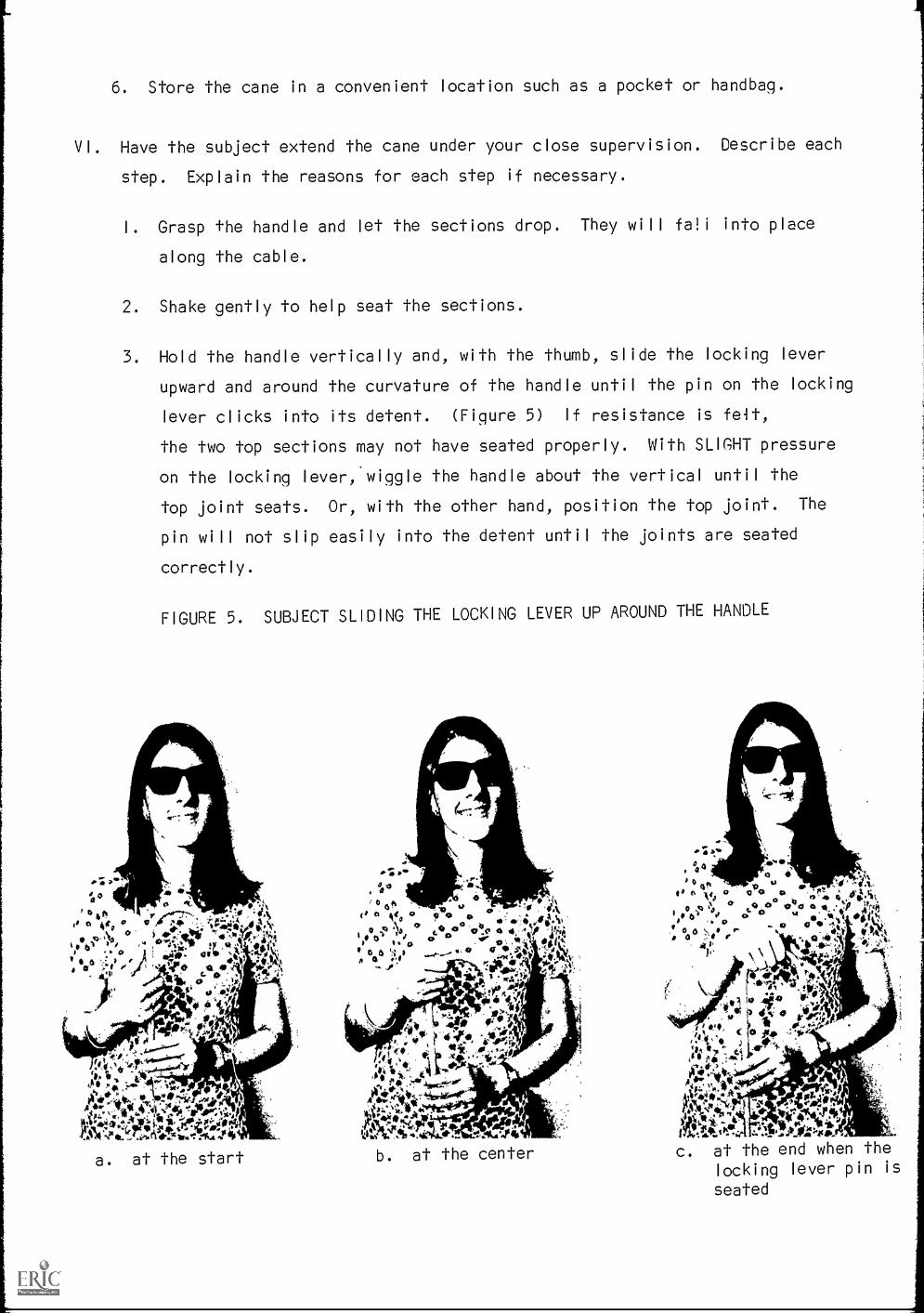
6. Store the cane in a convenient location such as a pocket or handbag.
VI. Have the subject extend the cane under your close supervision. Describe each
step. Explain the reasons for each step if necessary.
I. Grasp the handle and let the sections drop. They will fa!i into place
along the cable.
2. Shake gently to help seat the sections.
3. Hold the handle vertically and, with the thumb, slide the locking lever
upward and around the curvature of the handle until the pin on the locking
lever clicks into its detent. (Figure 5) If resistance is felt,
the two top sections may not have seated properly. With SLIGHT pressure
on the locking lever:wiggle the handle about the vertical until the
top joint seats. Or, with the other hand, position the top joint. The
pin will not slip easily into the detent until the joints are seated
correctly.
FIGURE 5. SUBJECT SLIDING THE LOCKING LEVER UP AROUND THE HANDLE
0 #k
Ab.ir .,- w to,
Ait°4***I14.1.Q1
a. at the start
0,,,Sago .0
b. at the center
Ai'.
ao .x
000 0 ,a , I, ,A q , : ,.
g 0 0'0 4 a Y Irloso0 v ., .titts ati s.,,,- a1
,
a NI 1,,;. ,..p.',..,
t41A'art
4o 11p IN riPAA, *
tCSe" lr."
041t.*Ai**,
4111:-sik.
,11VII --at
c. at the end when thelocking lever pin is
seated

CAUTION
Do not force the locking handle pin into the detent
unless the cane is completely assembled. To do so will strain
the cable and will lead to premature failure.
4. Press the locking lever towards the handle until the locking pawl seats.
(Figure 6) The cane is now ready for use.
VII. Let the subject repeat the folding
and extending operations under your
supervision until satisfied of his
proficiency in these operations. Use
more than one session if necessary.
VIII. Administer the General Information
and Pre-Test Questionnaire.
IX. Give the subject the shipping container
and Malfunctioning Folding Cane Report
form in case the cane must be returned
for repairs.
X. After two months, administer the Post-
Test Questionnaire. If possible,
maintain contact and help the subject
with additional reports as necessary.
4:14
do o ° ,a *a o 0..
10 4 00
60
12,0 ..
0,
00 9::,,4;t*I'S'
44A
-"'--14-'470 Ill ;*e..i.,.*
A4,iijel...
, lc
.''''. 4 °re' -; * '74. t Coda, i'l
to0 0 D ti"1.41..0. .
0 0 0to00 o
Ilt,10 0V
° 0 0 61If i * 0 ` .
totIt*' 9 0. *giji 4 ,,,10, co
i4 41r V 4 ,
., fe 4 4 .0i.: ir -0°Si1.44''' O.:,- *:it.OL ,* * .., O plow. :oir
FIGURE 6. SUBJECT LOCKING THE CANE
Do not hesitate to contact us for any assistance or information you require.
Any comments or suggestions in the evaluation, design, or other aspects of the cane
will be appreciated.
PLEASE do not let the subject use the cane unless he is proficient in
folding and extending it and has signed the Release. Thank You.
The Sensory Aids Evaluation and Development Center
292 Main StreetCambridge, Massachusetts 02142
ph. (617) 864-6900 Ext. 5331
'70

F I
P-1 FL
Appendix 6. Electrified Per
4;7C 3 2,2-
Li 1.3 II
Q. SA/ /5-21/..,N
100
01 a

Electrified Perkins Brailler Triac Driver Schematic
(If 30
/00D
9:6ti IML1315-
DATE YMkREVI
t
07 3-0 -4-
D3 higioo TZ
12 IC)
411111111111101.01.0.P.
Of 14/11oui
-ri
nix
CR3 kiik,
SI.
TOLERANCES(EXCEPT AS NOTED)
DECIMAL Co MPo YE:A/TS L. r
2--c)0.31 1 2_,SCAL
FRACTIONAL TiTLEELE.. c-rRic. PERI<TRIAlc E
ANGULAR DATE DRAWING NUMBER
FAPAL '10062

ematic
DATE SYM REVISION RECORD AUTH,I DR.
i zR7 51° 'IL
---)VVV%
D3 holo 0 !r2-
1
i
)
4..
ID i
VI INtiout
riI
a3 A4h."1
Pip(
L I
SI_
TOLERANCES(EXCEPT AS NOTED)
DECIMAL
±
:: o m Po/VE:4/7J 1,.. I 57
2,'C)0.1 1 2- ,
CALE DR
AP DYED BY
FRACTIONAL
±
ANGULAR
±
TITLIE L., e: cr-Rid pp..: RK(1v57RiAc Q_Eivek ,ScrifelMT16.,DATE
FAPP!L 69
DRAWING NUMBER
7. 006 2-1 l

Appendix 7.
Sample Seminar Agenda
Sensory Aids Evaluation and Development Center
292 Main StreetCambridge, Mass. 02142
864-6900 x5331
I. Introductory Remarks
A. History and background of the Center
B. Current funding
C. Objectives and goals of the Center
II. Organization of the Center
A. Permanent staff
B. Consulting staff
C. Committees1 Steering2. National Advisory
III. The Center's initial charter
A. Evaluation of existing sensory aids and devices
B. Location of new aids for evaluation
C. Encouraging others to become involved in sensory aids
D. In-house development of sensory aids
E. Development of training procedures,for devices
F. Involvement in behavioral research under field test conditions
G. Development of standards for evaluation purposes
IV. Review of current activities at the Center
A. Crooked handle folding cane
1. History and comparison with other canes
2. Distribution and selection
3. Evaluation process
B. Electrified Perkins Brailler development project
C. High speed brailler embosser
1. Funded by a Hartford Foundation grant
2. Re-design and manufacture of 20 embossers
3. Demonstration
D. Pathsounder evaluation program
1. Pathsounder demonstration
2. Kay aid demonstration
E. Simultaneous braille and inkprint publication of The East India-
man by E. Meacham
F. The Sound Source Ball

1. Description and demonstration2. Field testing
V. Continuation Programs at the Center
A. Straight handle folding cane project1. Development and test2. Distribution and evaluation
B. Electrified Perkins Brailler program1. Distribution of 10 braillers2. Development and evaluation process
C. M.I.T. High Speed Braille Embosser field test and evaluationprogram
1. Terminal at the Center2. Simultaneous feild test operation3. Pilot demonstration program for the Perkins School for
the BlindD. Expanded Pathsounder Evaluation program
1. Large scale trainee program2. Instruction manual
E. Manufacture and distribution of Sound Source Ball1. Selection of test facilities2. Distribution of 10 Sound Source Balls
F. Other programs1. Mono-type compositor's tape2. Storage of compositor's tape
VI. Seminar activities of the Center
A. Columbia University Teacher's College, School of Special Educa-tion - August 19, 20, 1968
B. Northern Illinois University Novethber 13, 1968C. Easter Seal Convention - November 16, 1968D. Blind University Group - November 20, 1968E. Commission for the Blind - November 21, 1968F. Steering and National Advisory Committee joint meeting -
December 2, 1968G. Boston College, School of Peripatology - December 6, 1968
VII. Conferences
A. Mobility Conference - "Proceedings Conference for MobilityTrainers and Technologists" December 14, 15, 1967
B. Braille conference - "Proceedings Conference on New Processesin Braille Manufacture" February 8, 9, 1968
VIII. Industrial Participation with the Center
A. For purposes of manufacturing sensory aids devicesB. Stimulation of joint projectsC. Consultation with the CenterD. To stimulate new ideas
IX. Closing Remarks

XI. References
1. Proceedings: Conference on New Processes for Braille Manufac-
ture, 1968, organized and sponsored by the Center for Sensory
Aids Evaluation and Development, M.I.T., Feb. 8 & 9, 1968.
2. Proceedings: Braille Research and Development Conference,
sponsored by the Sensory Aids Evaluation and Development Center,
M.I.T., Friday, 18 November, 1966.
3. Proceedings: Conference for Mobility Trainers and Technologists,
sponsored by the Sensory Aids Evaluation and Development Center,
M.I.T., December 14 & 15, 1967.
4. Woodie Flowers: A Sound-Source Ball for Blind Children, Report
No. 70249-3, Engineering Projects Laboratory, Department of
Mechanical Engineering, M.I.T., June 1967.