Embed Size (px)
Citation preview

TRENCHLESS WATER MAIN REHABILITATION DESIGN CONSIDERATIONS
V. Firat Sever PE, PhDProject Manager and Senior Engineer
August 28, 2014Columbus, Ohio

Water Main Investment Needs
Source: AWWA – Buried No Longer: Confronting America’s Water Infrastructure Challenge
Water Quality
• Water quality degrades in distribution systems
• Most rehabilitation methods substantially increase water quality
• Issues with cement linings exposed to soft water or premature curing of polymers
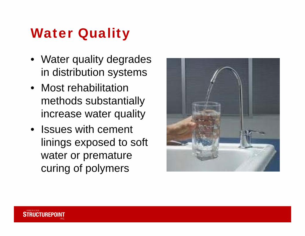
Water Loss
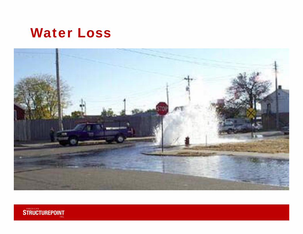
Structural Integrity
• Avoid failure• Depends on the
lining type• Class II and III
(AWWA) linings are semi-structural
• Class IV linings are fully structural
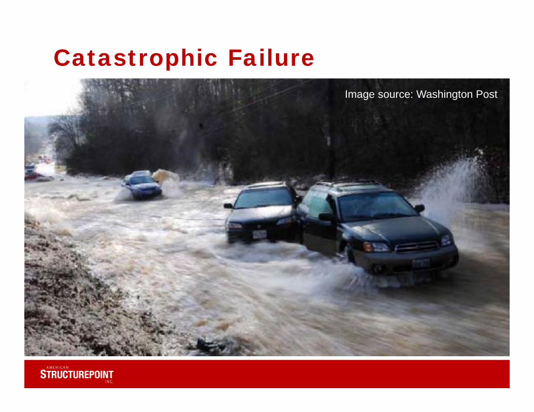
Catastrophic Failure Image source: Washington Post
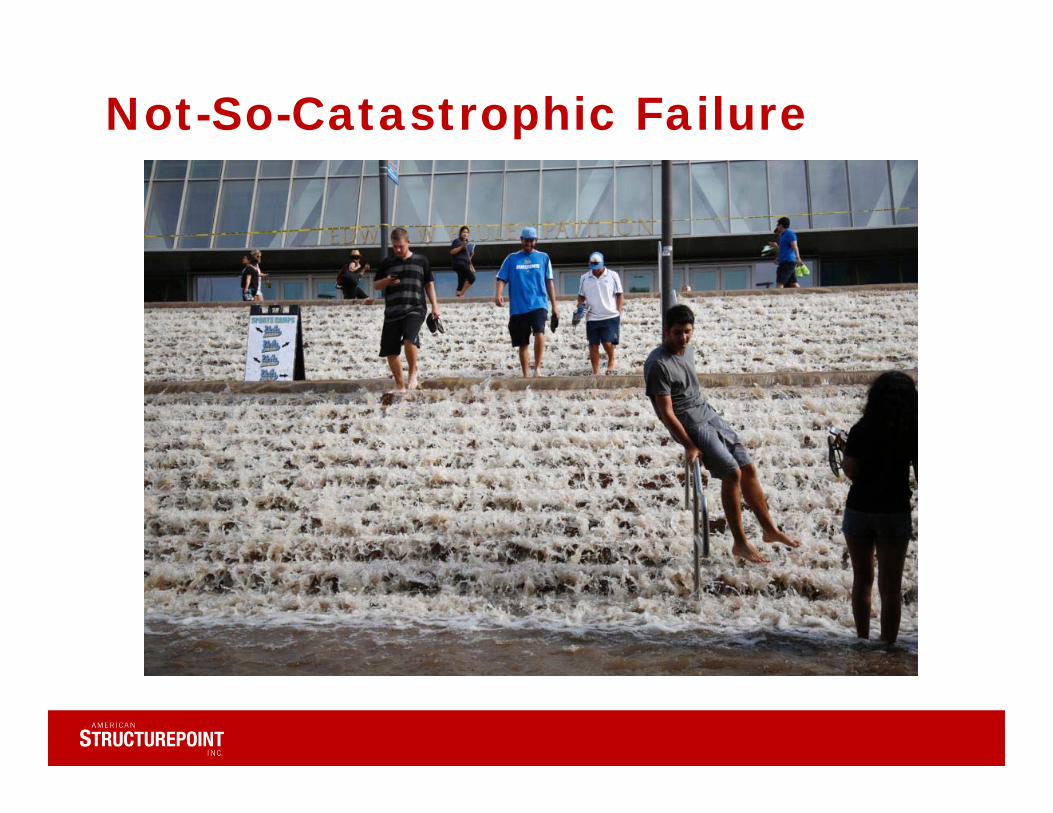
Not-So-Catastrophic Failure

Hydraulic Capacity

Basis of Water Main Rehabilitation
• Preserve/improve water quality
• Prevent water loss in the distribution system
• Prevent structural (catastrophic) failure
• Improve hydraulic capacity
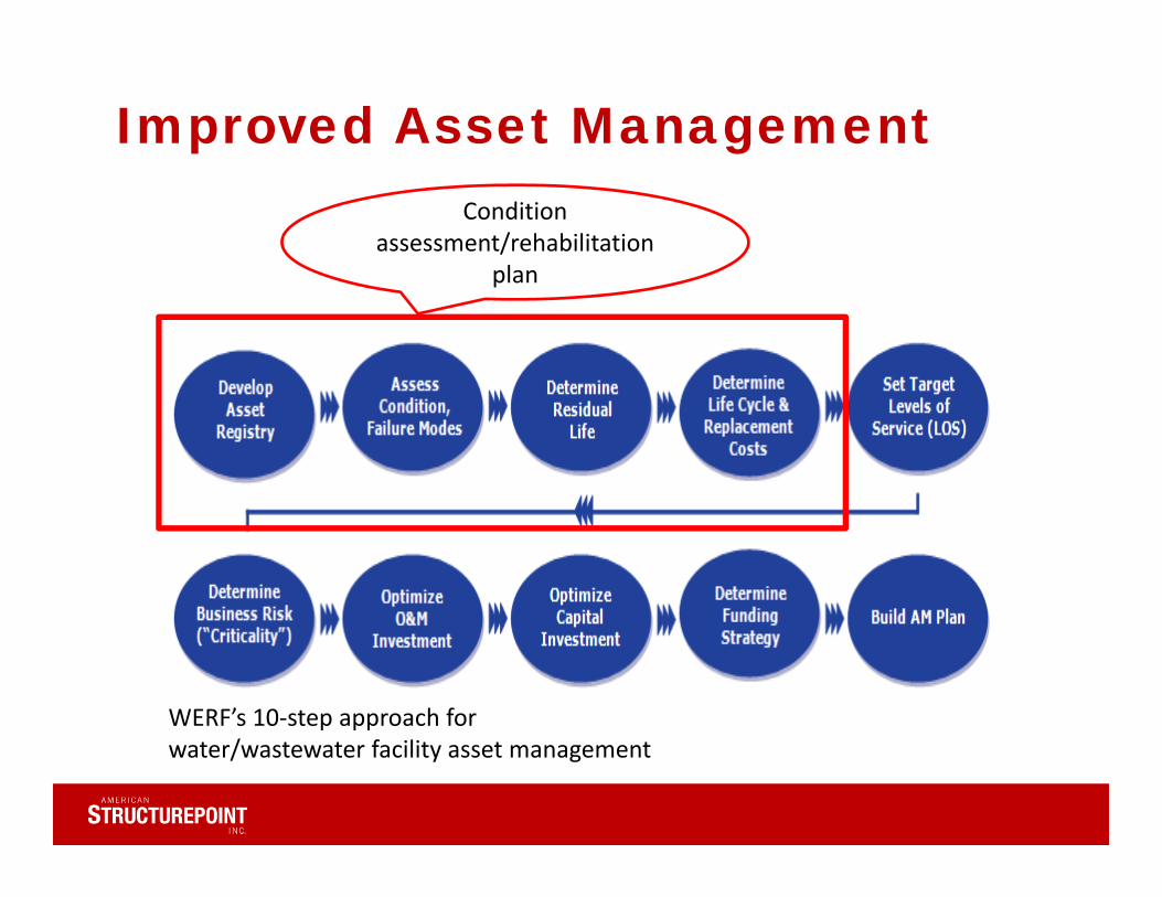
Improved Asset Management Condition
assessment/rehabilitation plan
WERF’s 10‐step approach for water/wastewater facility asset management
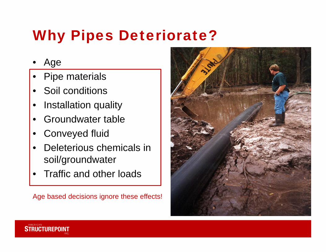
Why Pipes Deteriorate?
• Age• Pipe materials• Soil conditions• Installation quality• Groundwater table• Conveyed fluid• Deleterious chemicals in
soil/groundwater• Traffic and other loads
Age based decisions ignore these effects!

Issues w/ Open Cut Replacement
• Design life = 70 years (high end)
• Replacement rate = 0.5 % or typically less
• Economic cost• Impact damage• Social cost• Feasibility
Trenchless Rehab Cost Factors• Host pipe condition• Soil properties• Traffic• Pipe size• Market conditions• Design standards• Number of valves, fittings, service
connections• Contractor availability/bid competitiveness• Groundwater

Cement Mortar Lining
• Oldest method of water main relining
• May provide structural support with steel fiber reinforcement
• Issues with soft waters Image Source: Cement Lining Corp
International
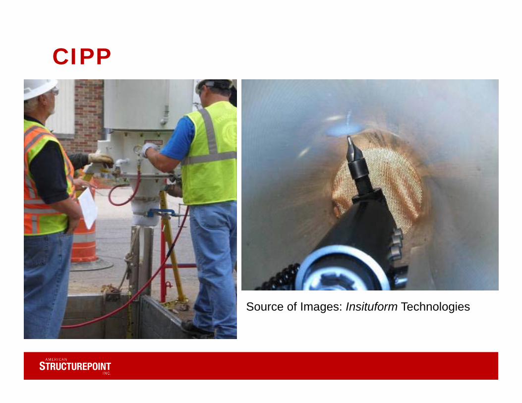
CIPP
Source of Images: Insituform Technologies
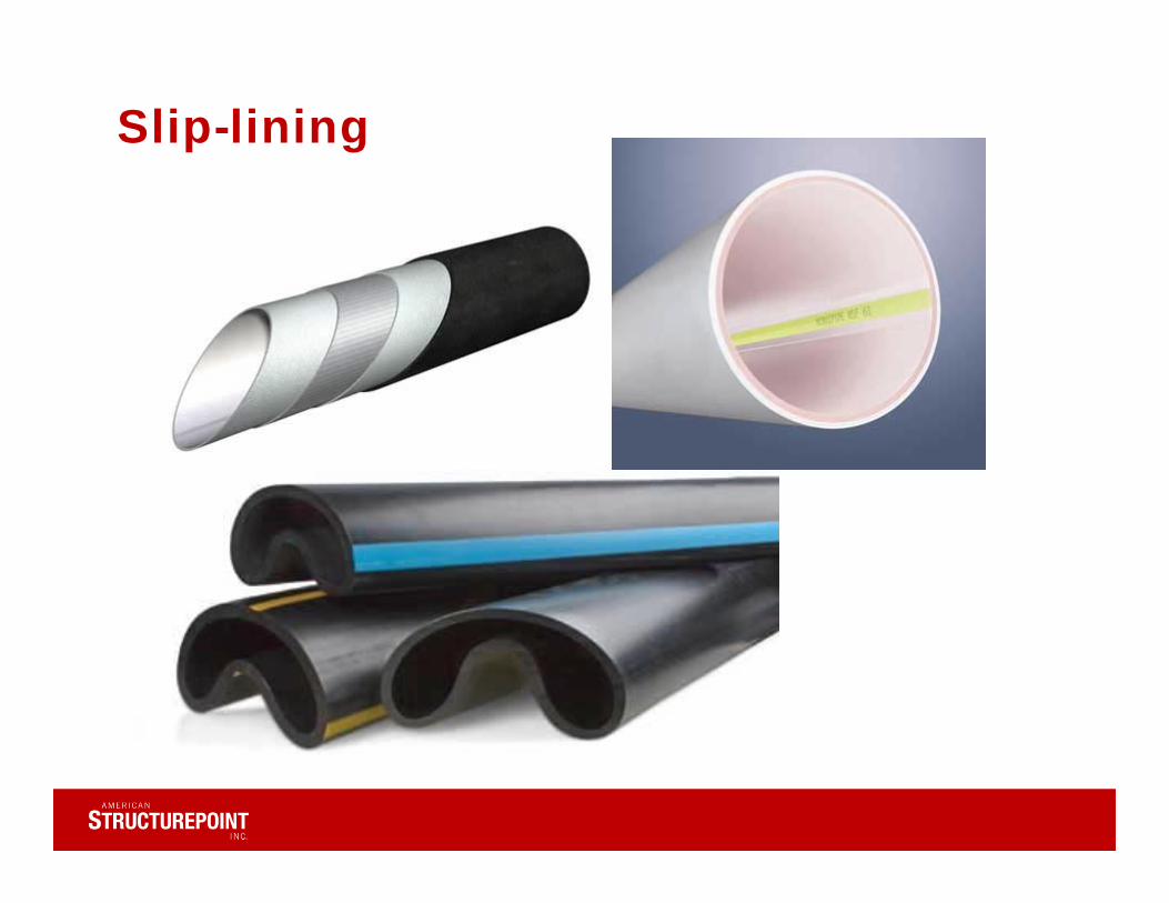
Slip-lining
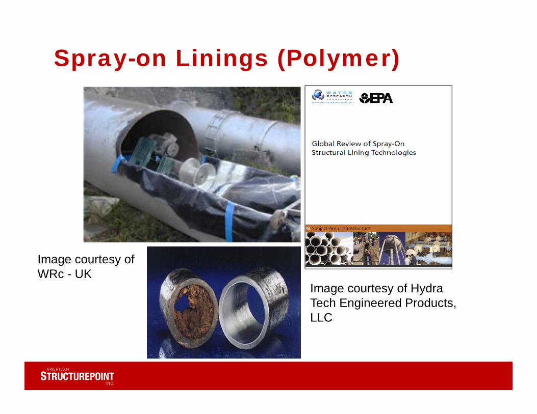
Spray-on Linings (Polymer)
Image courtesy of WRc - UK
Image courtesy of Hydra Tech Engineered Products, LLC
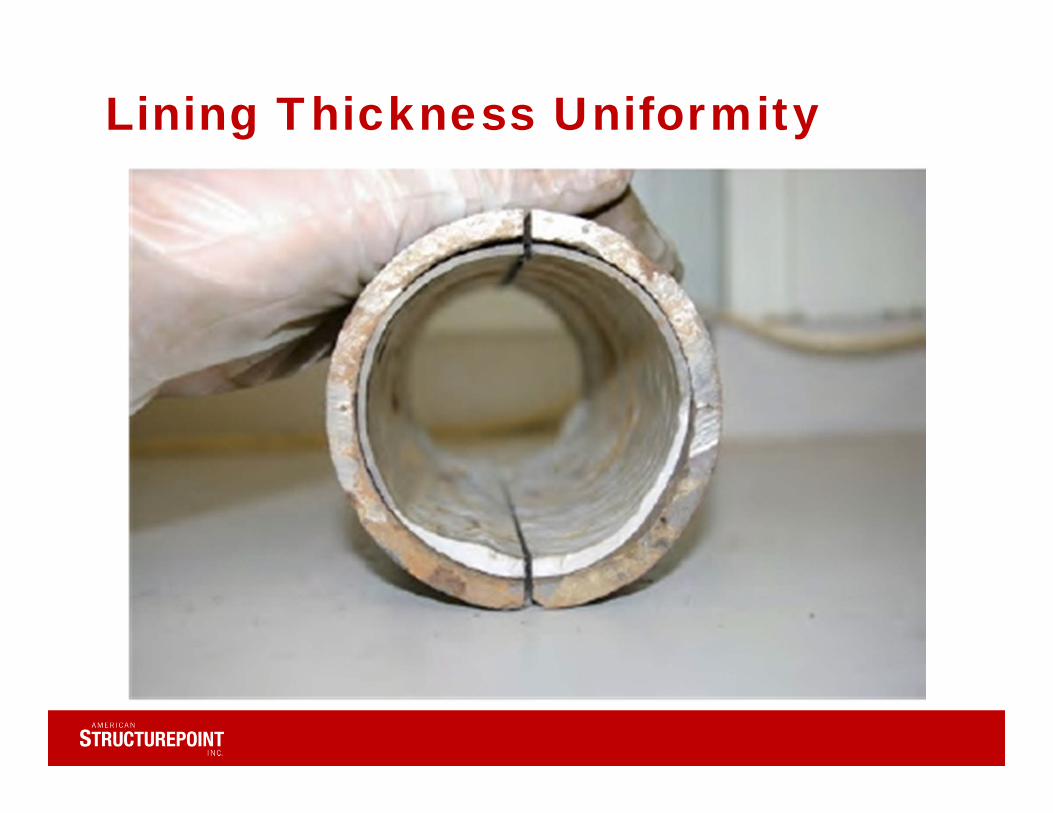
Lining Thickness Uniformity

Trenchless Replacement
• Where rehabilitation unfeasible due to host pipe conditions
• Upsizing needed–hydraulic capacity issues
• Competitive pricing• Methods include pipe
bursting and pipe eating• Replacement pipe materials
include HDPE, PVC, DISource of Image: TT Technologies
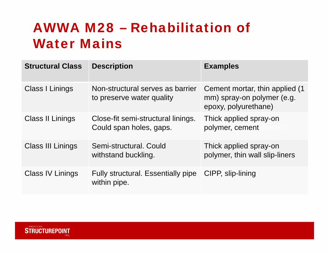
AWWA M28 – Rehabilitation of Water Mains
Structural Class Description Examples
Class I Linings Non-structural serves as barrier to preserve water quality
Cement mortar, thin applied (1 mm) spray-on polymer (e.g. epoxy, polyurethane)
Class II Linings Close-fit semi-structural linings. Could span holes, gaps.
Thick applied spray-onpolymer, cement mortar?
Class III Linings Semi-structural. Could withstand buckling.
Thick applied spray-on polymer, thin wall slip-liners
Class IV Linings Fully structural. Essentially pipe within pipe.
CIPP, slip-lining
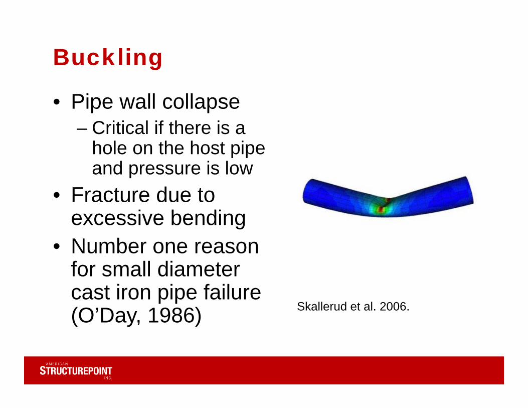
Buckling
• Pipe wall collapse– Critical if there is a
hole on the host pipe and pressure is low
• Fracture due to excessive bending
• Number one reason for small diameter cast iron pipe failure (O’Day, 1986) Skallerud et al. 2006.
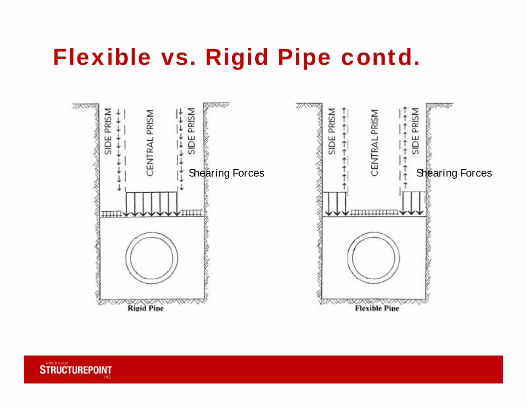
Flexible vs. Rigid Pipe contd.
Shearing Forces Shearing Forces
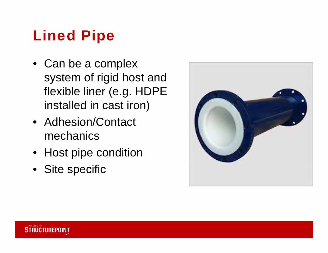
Lined Pipe
• Can be a complex system of rigid host and flexible liner (e.g. HDPE installed in cast iron)
• Adhesion/Contact mechanics
• Host pipe condition• Site specific
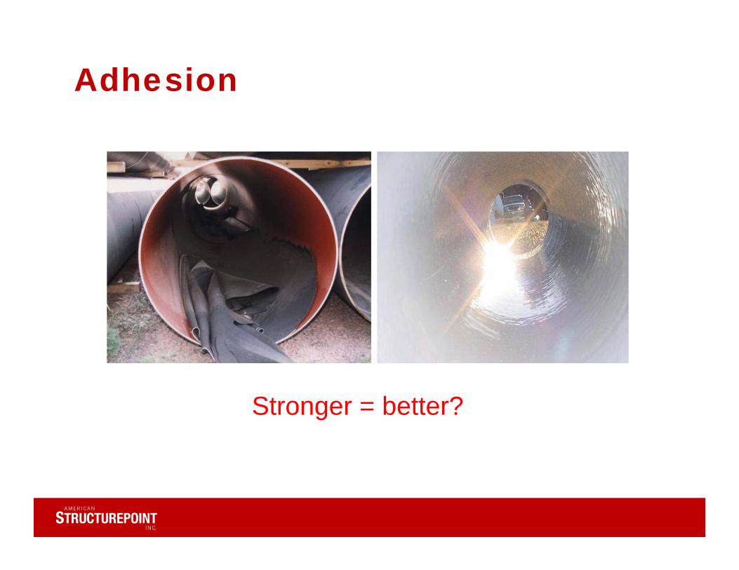
Adhesion
Stronger = better?
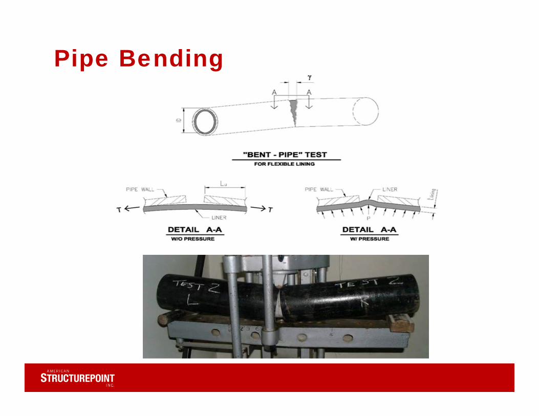
Pipe Bending
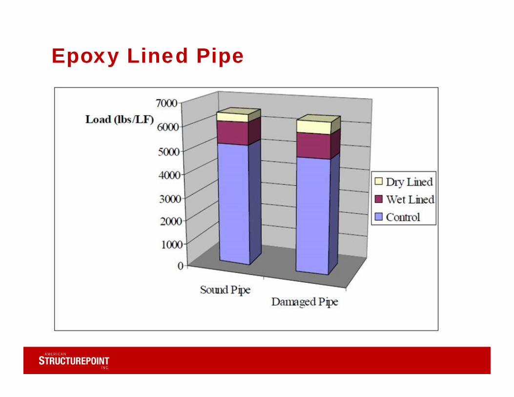
Epoxy Lined Pipe
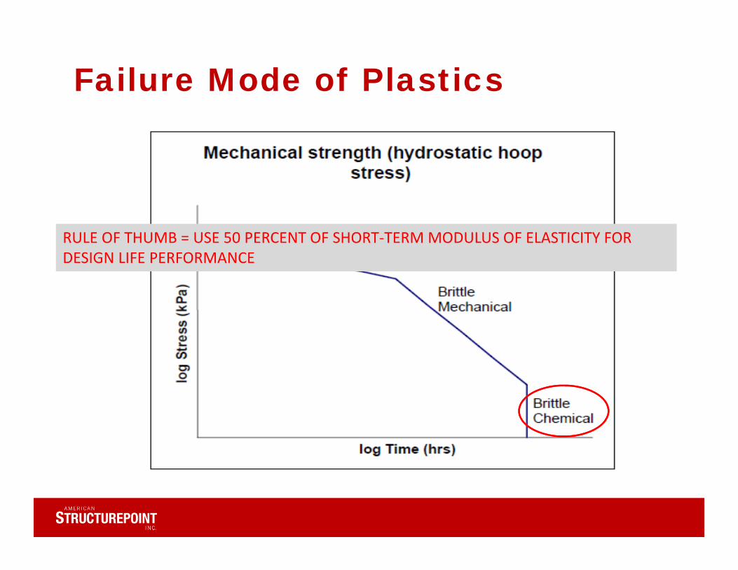
Failure Mode of Plastics
RULE OF THUMB = USE 50 PERCENT OF SHORT‐TERM MODULUS OF ELASTICITY FOR DESIGN LIFE PERFORMANCE
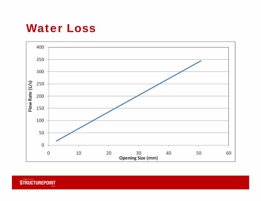
Water Loss
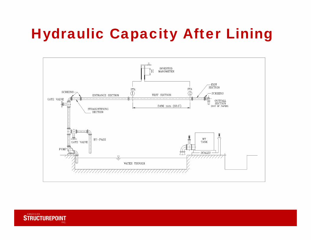
Hydraulic Capacity After Lining
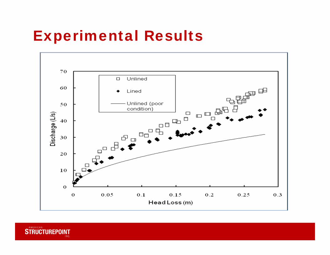
Experimental Results

Method SelectionCriteria Trenchless
Rehab (Lining)TrenchlessReplacement
Open‐cut Replacement
Project Objective
Feasibility
Cost (direct and social)
ServiceConnections/Valves
System Hydraulics
Host Pipe Condition
Other (e.g. contractor availability, bonding, insurance, regulatory)
Prepared for Teaching & Educational Purposes Only; 31

Material SelectionCriteria CIPP Cement SIPP
(Polymer)Close‐fit Slip‐liner FRP
HDPE PVC HDPE PVC
Project Objective
Feasibility
Host Pipe Condition
Cost
ServiceConnections/Valves
Prepared for Teaching & Educational Purposes Only; No Other Use Permitted

Installation – Access Pit
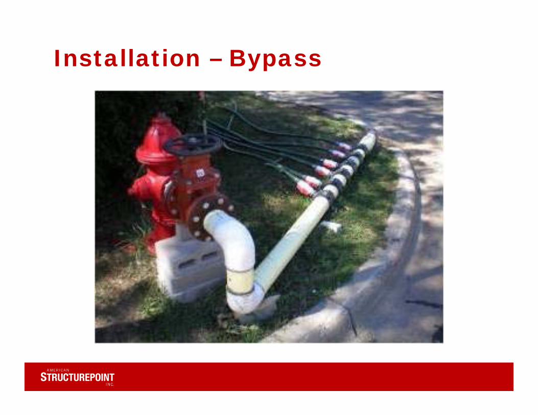
Installation – Bypass
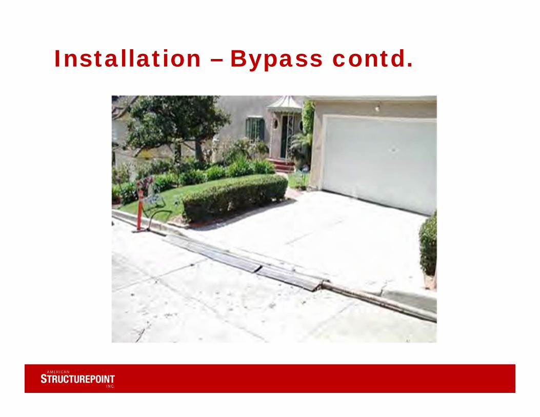
Installation – Bypass contd.
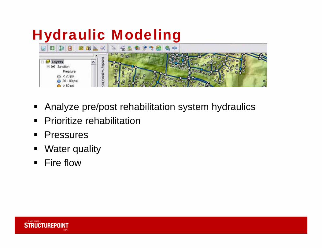
Hydraulic Modeling
Analyze pre/post rehabilitation system hydraulics Prioritize rehabilitation Pressures Water quality Fire flow

Hydrant Flow Test

Mapping/GIS
Pipe size: 6 inchMaterial: CIPEpoxy Lined (2013)
Pipe size: 6 inchMaterial: CIPEpoxy Lined (2013)
Regulatory
• Most water main linings on the North American market achieved NSF 61
• OEPA approves trenchless water main rehab
Conclusions
• Rehabilitation by relining:– Will preserve/improve water quality– Will improve structural integrity– Will prevent water loss– Can save significantly – Hydraulic capacity?
Conclusions contd.
• Hydraulic capacity: Depends on the host pipe and initial design conditions– Will likely improve existing capacity – Will likely reduce design capacity– High strength linings w/ high DR preferable
• Structural Integrity:– Complex… Need to analyze host pipe, site, soil,
etc. – Class I,II, III might serve the needs– There is no silver bullet - sound engineering
needed!
Questions?
V. Firat Sever, PhD, PE Senior Engineer/Project ManagerAmerican [email protected] (O)217-494-7569 (M)