Embed Size (px)
Citation preview
ITS of SMART (Storm Management And Road Tunnel)
August 2006
by
Ir Mohd Saleh Santhiman, Director of SMART Highway, LLM Looi Hong Weei, HOD-M&E, MGJV
Content• Overview• 3 Modes of Operation• Stormwater Components
– Flood Detection System– Flood Gate / Road Gate
• Motorway Components– Ventilation System– Lighting System– Heat Detection System– Fire and Emergency System– Radio Communication and Cellular System– CCTV
• Event 1 : Tunnel Closure from Mode 2 to Mode 3• Event 2 : Traffic Accident• Event 3 : Fire Accident
Overview
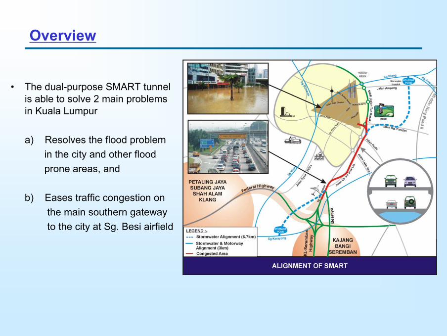
• The dual-purpose SMART tunnel is able to solve 2 main problems in Kuala Lumpur
a) Resolves the flood problemin the city and other floodprone areas, and
b) Eases traffic congestion onthe main southern gatewayto the city at Sg. Besi airfield
Overview
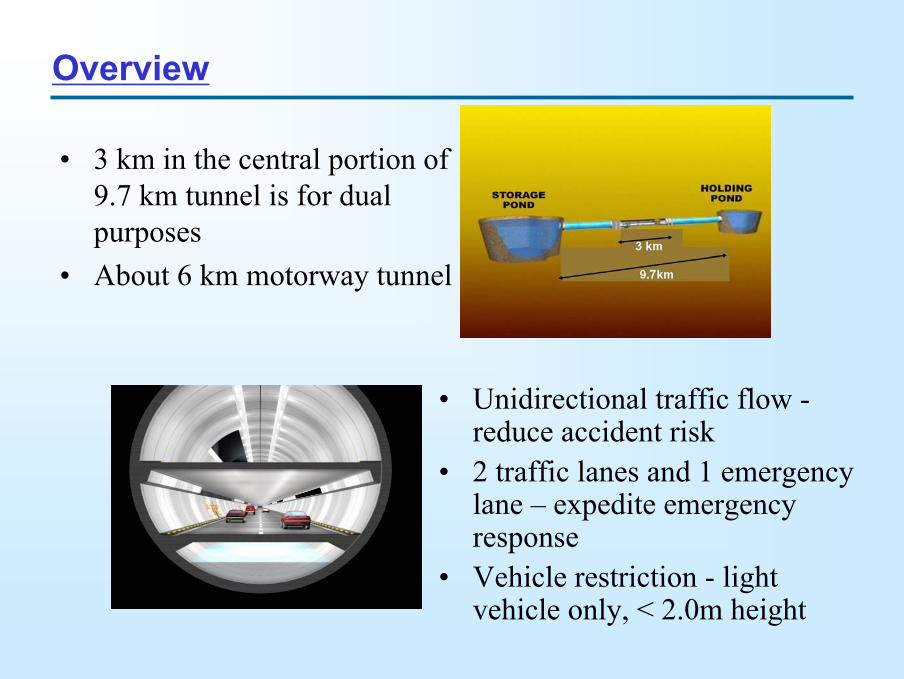
• 3 km in the central portion of 9.7 km tunnel is for dual purposes
• About 6 km motorway tunnel
• Unidirectional traffic flow -reduce accident risk
• 2 traffic lanes and 1 emergency lane – expedite emergency response
• Vehicle restriction - light vehicle only, < 2.0m height
TamanSalak
Selatan
LEGEND
LOT 10
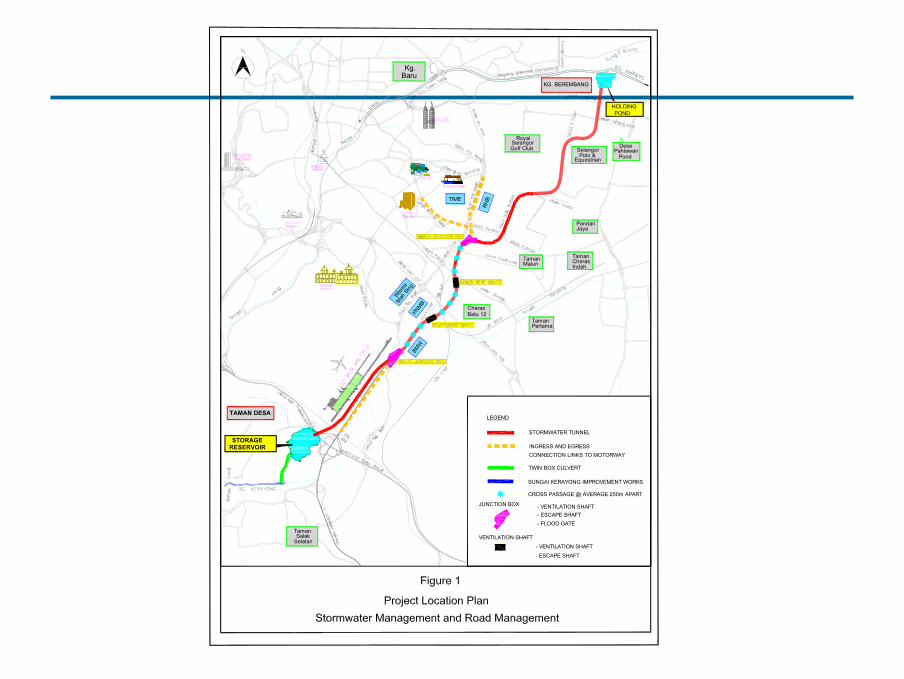
STORMWATER TUNNEL
INGRESS AND EGRESS CONNECTION LINKS TO MOTORWAY
TamanPertama
CherasBatu 12
HOLDINGPOND
SelangorPolo &
Equestrian
KG. BEREMBANG
DesaPahlawan
Pond
Jaya
TamanMaluri
TamanCheras Indah
Pandan
Kg. Baru
RoyalSelangorGolf Club
TWIN BOX CULVERT
SUNGAI KERAYONG IMPROVEMENT WORKS
CROSS PASSAGE @ AVERAGE 250m APART
- VENTILATION SHAFT
- VENTILATION SHAFT
JUNCTION BOX
- ESCAPE SHAFT- FLOOD GATE
VENTILATION SHAFT
- ESCAPE SHAFT
BMW
TIME
PNMB
Wism
aMah
Sing
RHB
RESERVOIR
TAMAN DESA
STORAGE
3 Modes of Operation
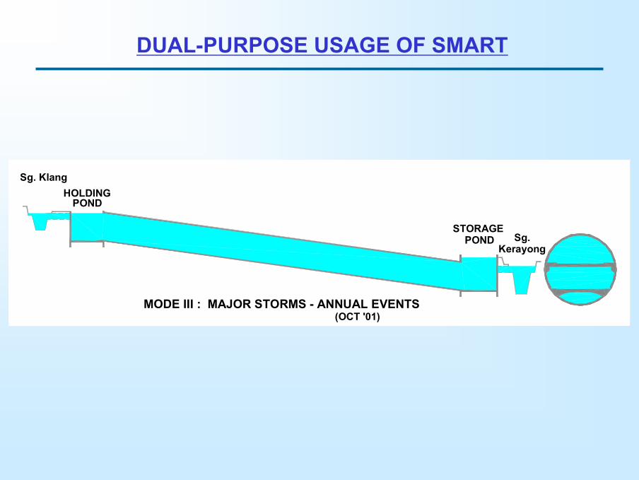
DUAL-PURPOSE USAGE OF SMART
HOLDINGPOND
STORAGE
MODE I : NO STORMS
POND
Sg. Klang
Sg.Kerayong
HOLDINGPOND
STORAGEPOND
Sg. Klang
Sg.Kerayong
MODE II : MOST STORMS - 7 TO 10 TIMESMODE III : MAJOR STORMS - ANNUAL EVENTS
HOLDINGPOND
STORAGEPOND
Sg. Klang
Sg.Kerayong
(OCT '01)

Stormwater Components
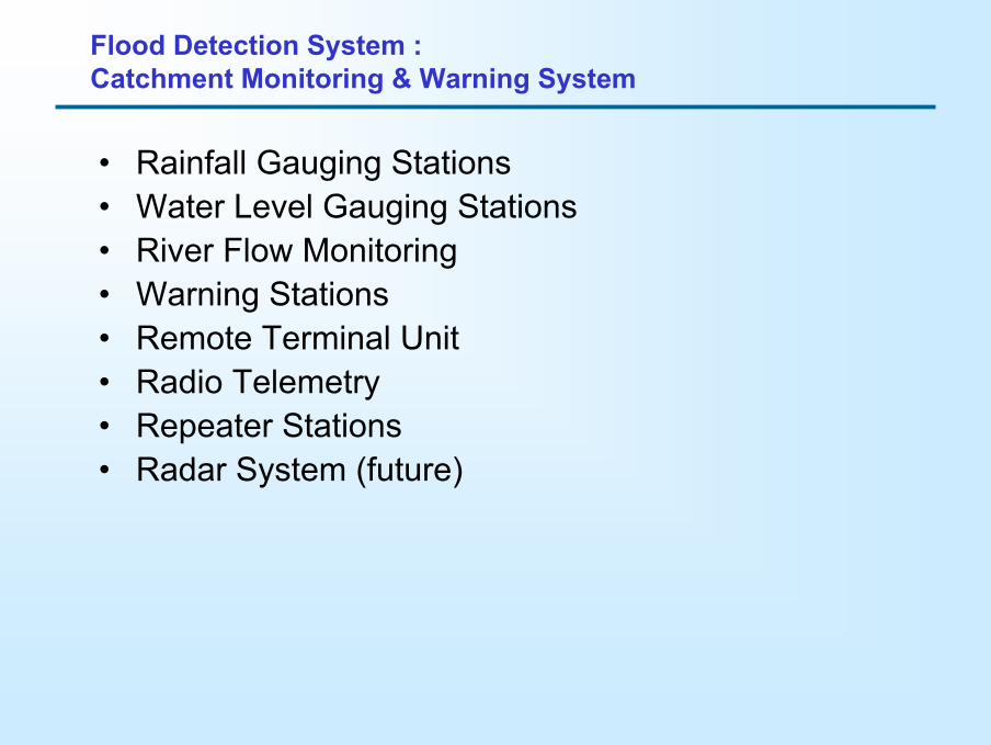
• Rainfall Gauging Stations• Water Level Gauging Stations• River Flow Monitoring• Warning Stations• Remote Terminal Unit• Radio Telemetry• Repeater Stations• Radar System (future)
Flood Detection System : Catchment Monitoring & Warning System
SUNGAI BATU CATCHMENT
SUNGAI BUNUS CATCHMENT
SUNGAI KLANG CATCHMENT
SUNGAI AMPANG CATCHMENT
SUNGAI GOMBAK CATCHMENT
KLANG GATES DAM CATCHMENT
KLANG GATES DAM
BATU DAM
SG. KERAYONGSG. KLANG
SG. K
LAN
G
SG. B
UNUS
SG. A
MPA
NG
SG. G
OM
BAK
SG. B
ATU
SUNGAI KERAYONGCATCHMENT
3.3.53.3.4
3.1.14 3.3.33.3.2
3.3.1
3.2.9 3.2.6
3.2.4
3.1.13
3.2.12
3.1.10
3.1.4
3.1.8
3.1.3 3.1.2
3.1.1
3.1.12
3.2.5
3.1.7
3.1.9
3.1.11
3.2.23.1.6
3.1.53.2.8
3.2.11
3.2.103.2.7
3.2.3
3.2.1
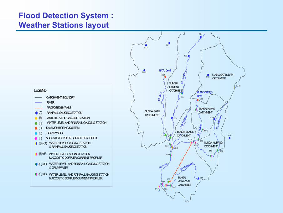
LEGEND
CATCHMENT BOUNDRYRIVERPROPOSED BYPASSRAINFALL GAUGING STATION
WATER LEVERL GAUGING STATIONWATER LEVEL AND RAINFALL GAUGING STATIONDAM MONITORING SYSTEMCRUMP WEIRACCOSTIC DOPPLER CURRENT PROFILER
WATER LEVEL GAUGING STATION& RAINFALL GAUGING STATION
WATER LEVEL GAUGING STATION& ACCOSTIC DOPPLER CURRENT PROFILER
WATER LEVEL AND RAINFALL GAUGING STATION& CRUMP WEIR
WATER LEVEL AND RAINFALL GAUGING STATION& ACCOSTIC DOPPLER CURRENT PROFILER
(A)
(B)
(C)(D)
(E)(F)
(B)+(A)
(B)+(F)
(C)+(E)
(C)+(F)
Flood Detection System : Weather Stations layout
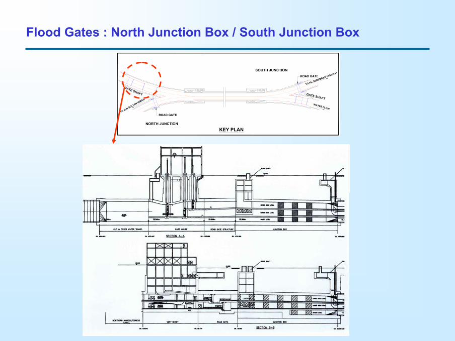
TO JLN SULTAN ISMAIL
WATER FLOW
TO KL-SEREMBAN HIGHWAY
NORTH JUNCTION
SOUTH JUNCTION
GATE SHAFT
GATE SHAFT
KEY PLAN
ROAD GATE
ROAD GATE
Flood Gates : North Junction Box / South Junction Box
TO JLN SULTAN ISMAIL
WATER FLOW
TO KL-SEREMBAN HIGHWAY
NORTH JUNCTION
SOUTH JUNCTION
GATE SHAFT
GATE SHAFT
KEY PLAN
ROAD GATE
ROAD GATE
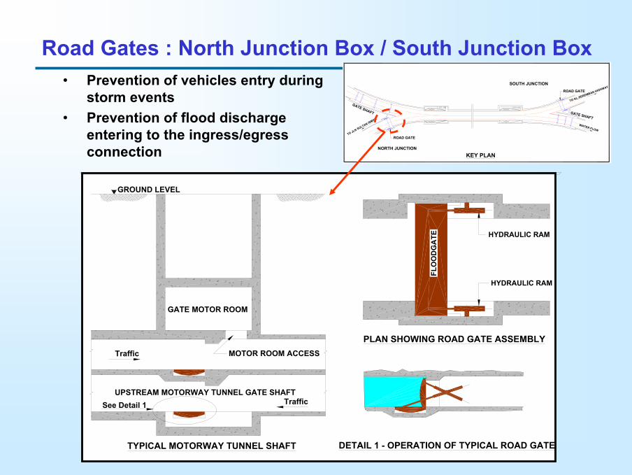
• Prevention of vehicles entry during storm events
• Prevention of flood discharge entering to the ingress/egress connection
UPSTREAM MOTORWAY TUNNEL GATE SHAFT
MOTOR ROOM ACCESS
GROUND LEVEL
FLO
OD
GA
TE
GATE MOTOR ROOM
HYDRAULIC RAM
HYDRAULIC RAM
TYPICAL MOTORWAY TUNNEL SHAFT DETAIL 1 - OPERATION OF TYPICAL ROAD GATE
PLAN SHOWING ROAD GATE ASSEMBLY
Traffic
Traffic
See Detail 1
Road Gates : North Junction Box / South Junction Box

Motorway Components
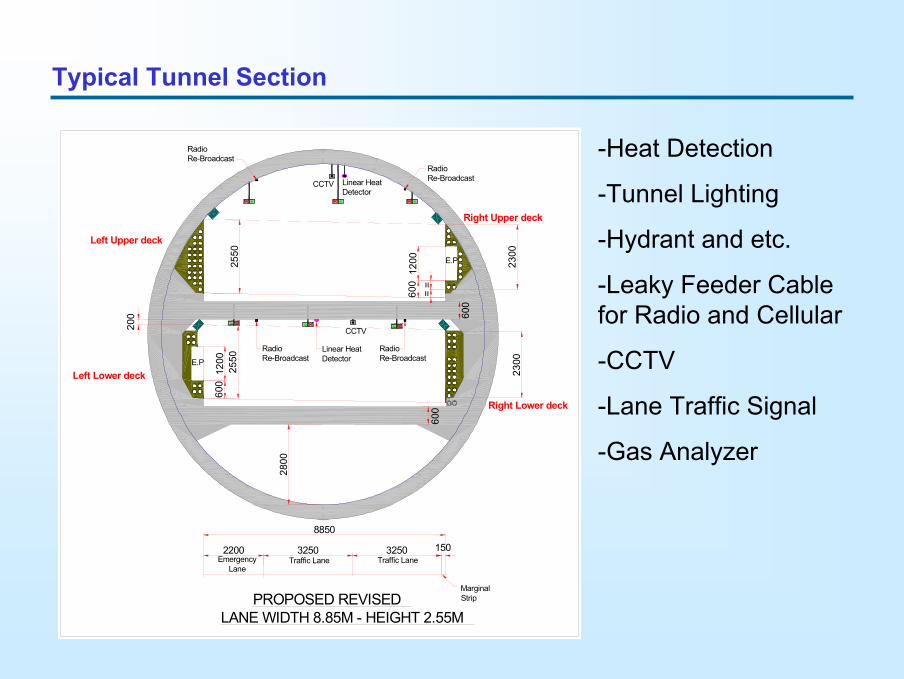
Typical Tunnel Section
600
600
200
2550
2800
PROPOSED REVISEDLANE WIDTH 8.85M - HEIGHT 2.55M
2200 3250 3250 150
8850
Traffic LaneTraffic LaneEmergency Lane
MarginalStrip
2550
Right Upper deck
600
==
1200
Right Lower deck
Left Upper deck
Left Lower deck
E.P 2300
1200
600
2300E.P
RadioRe-BroadcastLinear Heat
DetectorCCTV
RadioRe-Broadcast
CCTV
Linear HeatDetector
RadioRe-Broadcast
RadioRe-Broadcast
-Heat Detection
-Tunnel Lighting
-Hydrant and etc.
-Leaky Feeder Cable for Radio and Cellular
-CCTV
-Lane Traffic Signal
-Gas Analyzer
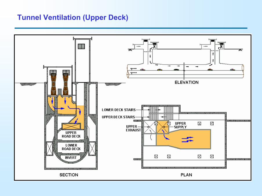
Tunnel Ventilation (Upper Deck)
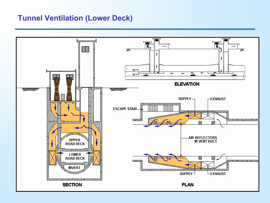
Tunnel Ventilation (Lower Deck)
Th - Threshold Zone
Tr1 - Transition Zone 1
Tr2 - Transition Zone 2
Tr3 - Transition Zone 3
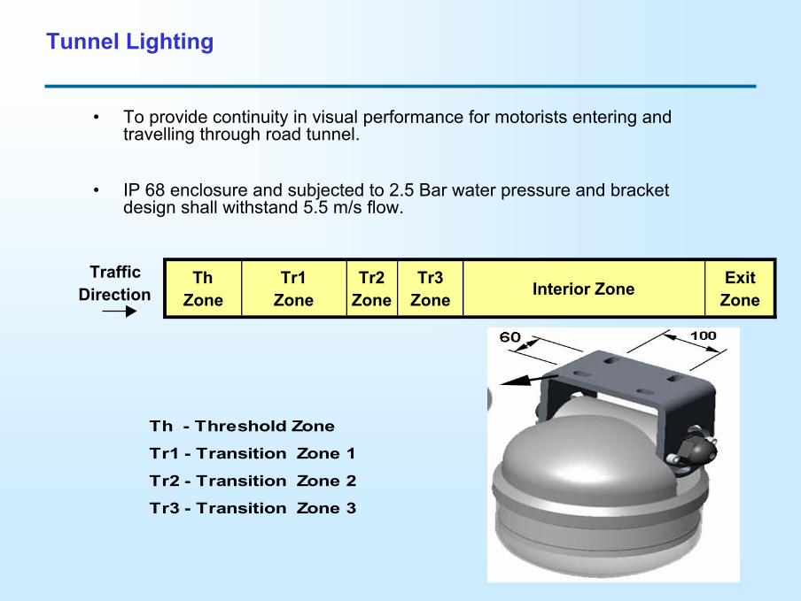
Tunnel Lighting
Traffic Direction
ThZone
Tr1Zone
Tr2 Zone
Tr3Zone Interior Zone Exit
Zone
• To provide continuity in visual performance for motorists entering and travelling through road tunnel.
• IP 68 enclosure and subjected to 2.5 Bar water pressure and bracket design shall withstand 5.5 m/s flow.
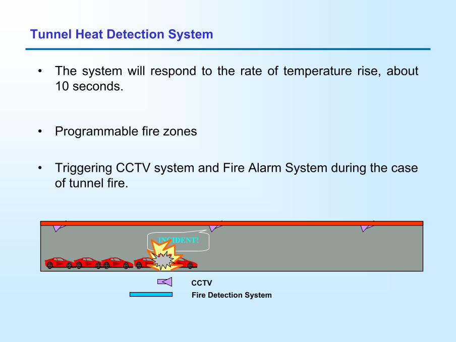
• The system will respond to the rate of temperature rise, about 10 seconds.
• Programmable fire zones
• Triggering CCTV system and Fire Alarm System during the case of tunnel fire.
Fire Detection System
INCIDENT!
CCTV
FIRE
Tunnel Heat Detection System
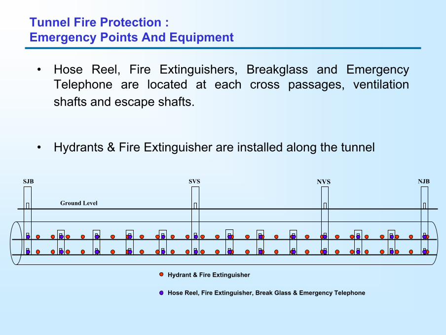
Tunnel Fire Protection : Emergency Points And Equipment
• Hose Reel, Fire Extinguishers, Breakglass and Emergency Telephone are located at each cross passages, ventilation shafts and escape shafts.
• Hydrants & Fire Extinguisher are installed along the tunnel
NJBNVSSVSSJB
Ground Level
Hydrant & Fire Extinguisher
Hose Reel, Fire Extinguisher, Break Glass & Emergency Telephone
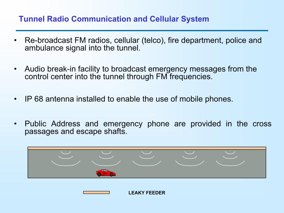
• Re-broadcast FM radios, cellular (telco), fire department, police and ambulance signal into the tunnel.
• Audio break-in facility to broadcast emergency messages from the control center into the tunnel through FM frequencies.
• IP 68 antenna installed to enable the use of mobile phones.
• Public Address and emergency phone are provided in the cross passages and escape shafts.
Tunnel Radio Communication and Cellular System
LEAKY FEEDER
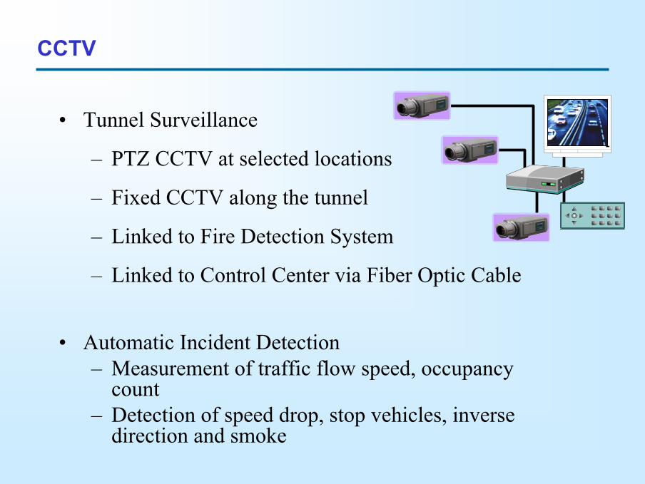
• Tunnel Surveillance
– PTZ CCTV at selected locations
– Fixed CCTV along the tunnel
– Linked to Fire Detection System
– Linked to Control Center via Fiber Optic Cable
• Automatic Incident Detection – Measurement of traffic flow speed, occupancy
count – Detection of speed drop, stop vehicles, inverse
direction and smoke
CCTV
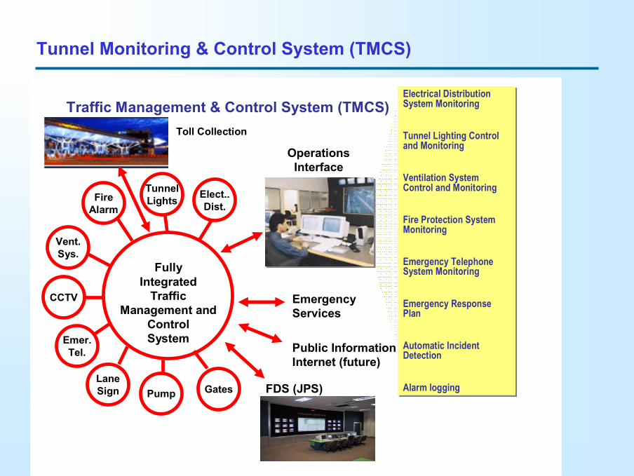
Tunnel Monitoring & Control System (TMCS)
Emer.Tel.
CCTV
LaneSign
Vent.Sys.
FireAlarm
TunnelLights Elect..
Dist.
EmergencyServices
Public InformationInternet (future)
FullyIntegrated
Traffic Management and
ControlSystem
Electrical Distribution System Monitoring
Tunnel Lighting Control and Monitoring
Ventilation System Control and Monitoring
Fire Protection System Monitoring
Emergency Telephone System Monitoring
Emergency Response Plan
Automatic Incident Detection
Alarm logging
Electrical Distribution System Monitoring
Tunnel Lighting Control and Monitoring
Ventilation System Control and Monitoring
Fire Protection System Monitoring
Emergency Telephone System Monitoring
Emergency Response Plan
Automatic Incident Detection
Alarm logging
Operations Interface
Traffic Management & Control System (TMCS)
Pump Gates FDS (JPS)
Toll Collection
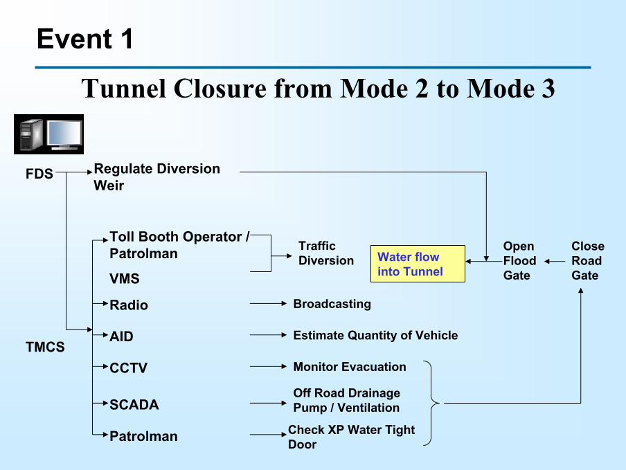
Event 1
Tunnel Closure from Mode 2 to Mode 3
FDS
TMCS
Toll Booth Operator / Patrolman
VMS
Traffic Diversion
Radio Broadcasting
AID Estimate Quantity of Vehicle
CCTV Monitor Evacuation
SCADAOff Road Drainage Pump / Ventilation
Patrolman Check XP Water Tight Door
Regulate Diversion Weir
Water flow into Tunnel
Open Flood Gate
Close Road Gate
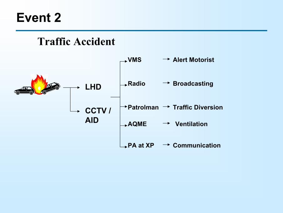
Event 2
Traffic Accident
CCTV / AID
LHD
Patrolman Traffic Diversion
VMS Alert Motorist
Radio Broadcasting
AQME Ventilation
PA at XP Communication
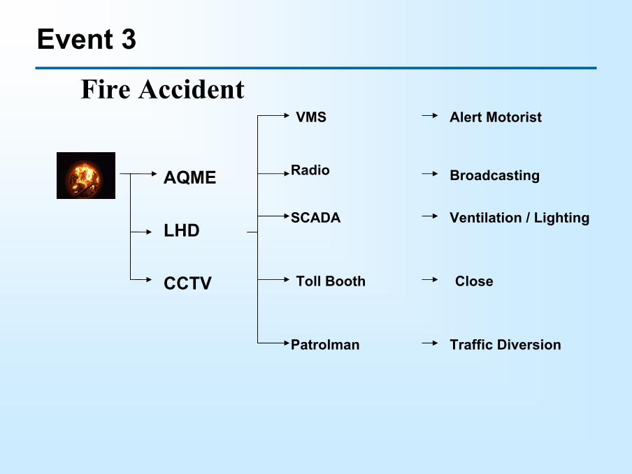
Event 3
Fire Accident
Radio Broadcasting
Patrolman Traffic Diversion
Toll Booth Close
Alert MotoristVMS
SCADA Ventilation / Lighting
CCTV
LHD
AQME
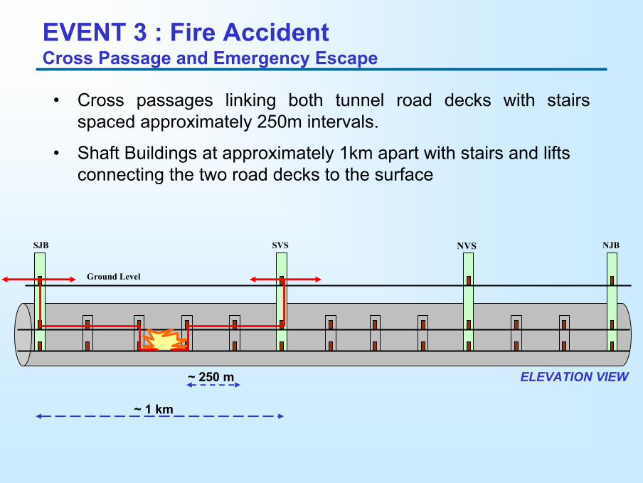
EVENT 3 : Fire Accident Cross Passage and Emergency Escape
• Cross passages linking both tunnel road decks with stairs spaced approximately 250m intervals.
• Shaft Buildings at approximately 1km apart with stairs and liftsconnecting the two road decks to the surface
NJBNVSSVSSJB
Ground Level
~ 1 km
~ 250 m ELEVATION VIEW
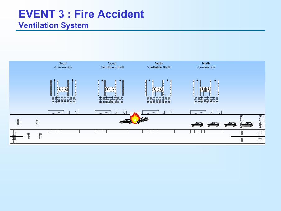
SouthJunction Box
SouthVentilation Shaft
NorthVentilation Shaft
NorthJunction Box
EVENT 3 : Fire Accident Ventilation System
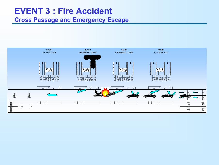
EVENT 3 : Fire Accident Cross Passage and Emergency Escape
SouthJunction Box
SouthVentilation Shaft
NorthVentilation Shaft
NorthJunction Box
THANK YOUTerima Kasih
www.smarttunnel.com.my


![ModelIdentificationforAdvancedTunnelVentilation Control€¦ · nationalguidelines[PIARC(2011)],suchasRVSinAustria[RVS09.02.31(2014)],RABT in Germany [RABT(2006)], ASTRA in Switzerland](https://img.pdfslide.us/doc/110x75/60967291b7cdac23505fa192/modelidentiicationforadvancedtunnelventilation-control-nationalguidelinespiarc2011suchasrvsinaustriarvs0902312014rabt.jpg)