Embed Size (px)
Citation preview

Mike's Electronic Parts, LLCAudio Amplifier Kit 1
Page 1https://www.mikeselectronicparts.com/
Mike's Electronic Parts
R3
100K
C1
.001
uf
Q1
PN10
0A
VR1
100K
R1
4.7M
R2
10K
EAR OUT
9 VOLT
EAR GND
C2
.1uf
C3
10uf
INPUT
GND
31
2
NEGPOS

1 - Circuit Board 1 - 100K Variable Resistor Pre-soldered To Circuit Board1 - PN100A Transistor1 - .001uf Capacitor (marked 102)1 - .1uf Capacitor (marked 104)1 - 10uf Capacitor1 - 4.7M Resistor (yellow violet green gold)1 - 10K Resistor (brown black orange gold)1 - 100K Resistor (brown black yellow gold)1 - Ceramic Earphone1 - 9 Volt Battery Clip4 - Fahnestock Clips1 - Knob17 - 3/8" #6 Screws4 - 3/4" #6 Screws38 - #6 Nuts17 - #6 Washers4 - Rubber Feet2 - ~1 foot wire
Parts List
Mike's Electronic Parts, LLCAudio Amplifier Kit 1
Knob
Ceramic Earphone.001uf Capacitor
Fahnestock Clip Rubber Foot
Circuit Board
3/8" #6 Screw 3/4" #6 Screw #6 Washer #6 Nut
https://www.mikeselectronicparts.com/ Page 2
Philips Screwdriver5/16" Wrench
Tools Required
100K Variable Resistor
100K Resistor4.7M Resistor 10K Resistor
PN100A 10uf Capacitor
9 Volt Battery Clip
Wire
.1uf Capacitor

Mike's Electronic Parts, LLCAudio Amplifier Kit 1
AssemblyLocate and familiarize yourself with all the parts in the parts list.1.
2.
https://www.mikeselectronicparts.com/ Page 3
Audio Amplifier Kit 1 is a fun and simple project for both beginners and expert builders alike. Everything needed to build a fully functional audio amplifier is included in the kit. Easy to assemble with no soldering required. Audio Amplifier Kit 1 is a great project to build with your child or grandchild, boy scout groups and schools.
Audio Amplifier Kit 1 was designed to compliment our Crystal Radio Kit 4. The amplifier was tested and designed for use with our cyrstal radio and radio IC kits. The amplifier should work well with other home built radios but was not designed as a general purpose amplifier for mp3 players, phones and the like. The kit was designed for use with a high impedance headphone or earphone with 2,000 ohm or higher impedance. The kit has been tested with all the headphones and earphones available on our site. Using headphones or earphones with less than 2,000 ohms impedance may work acceptably, however that was not the kits design so performance may suffer.
The kit contains small parts that may be a choking hazard. Adult supervision is always advised while building the kit.
Assemble the posts.Items used: 6 - 3/8" #6 Screws, 6 #6 Nuts.Push a 3/8" #6 screw through the circuit board from the bottom. Use a #6 nut from the top to fasten the screw to the circuit board.Repeat for the remaining holes in the circuit board.
Assemble the legs.Items used: 4 - 3/4" #6 Screws, 4 #6 Nuts, 4 - Fahnestock Clips, 4 - Rubber Feet.Insert a 3/4" #6 screw through a Fahnestock Clip. Insert the screw with fahnestock clip through the circuit board. Attach a #6 nut from the bottom side of the circuit board. Snug the nut, do not over tighten. Push a rubber foot over the bottom of the screw. Lightly turn the rubber foot clockwise to ensure it is fully pushed into the screw.Repeat for all four legs.
3.
Assembly Continued
Mike's Electronic Parts, LLCAudio Amplifier Kit 1
4.
5.
https://www.mikeselectronicparts.com/ Page 4
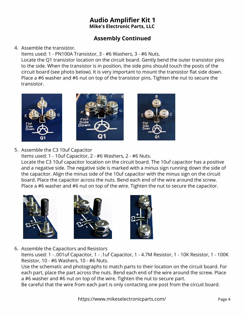
Assemble the transistor.Items used: 1 - PN100A Transistor, 3 - #6 Washers, 3 - #6 Nuts.Locate the Q1 transistor location on the circuit board. Gently bend the outer transistor pins to the side. When the transistor is in position, the side pins should touch the posts of the circuit board (see photo below). It is very important to mount the transistor flat side down. Place a #6 washer and #6 nut on top of the transistor pins. Tighten the nut to secure the transistor.
Assemble the C3 10uf CapacitorItems used: 1 - 10uf Capacitor, 2 - #6 Washers, 2 - #6 Nuts.Locate the C3 10uf capacitor location on the circuit board. The 10uf capacitor has a positive and a negative side. The negative side is marked with a minus sign running down the side of the capacitor. Align the minus side of the 10uf capacitor with the minus sign on the circuit board. Place the capacitor across the nuts. Bend each end of the wire around the screw. Place a #6 washer and #6 nut on top of the wire. Tighten the nut to secure the capacitor.
6. Assemble the Capacitors and ResistorsItems used: 1 - .001uf Capacitor, 1 - .1uf Capacitor, 1 - 4.7M Resistor, 1 - 10K Resistor, 1 - 100K Resistor, 10 - #6 Washers, 10 - #6 Nuts.Use the schematic and photographs to match parts to their location on the circuit board. For each part, place the part across the nuts. Bend each end of the wire around the screw. Place a #6 washer and #6 nut on top of the wire. Tighten the nut to secure part.Be careful that the wire from each part is only contacting one post from the circuit board.

Assembly Continued
Mike's Electronic Parts, LLCAudio Amplifier Kit 1
https://www.mikeselectronicparts.com/
Attach the 9 Volt Battery Clip.Items used: 1 - 9 Volt Battery Clip, 2 - #6 Washers, 2 - #6 Nuts.Locate the 9V Battery location on the circuit board. Attach the black wire to the negative (minus) post and the red wire to the positive (plus) post.
9.
Page 5
Attach the kob.Items used: 1 - Knob.Turn the variable resistor shaft full left. Press the knob onto the shaft of the variable resistor (VR1) aligning the marking of the knob with the left markings of the circuit board. The knob will fit tight and require a good amount of pressure to attach.
10.
Attach the earphone.Items used: 1 - Ceramic Earphone.Locate the Fahnestock clips marked EAR. Push down on the fahnestock clip. Slide the end of the earphone wire through the opening. Release the fahnestock clip. Note: Do not clip the wire by the plactic coating. The bare metal portion of the wire must be clamped by the fahnestock clip.
11.
Operation
Attach the audio amplifier to your radio. Attach the GND to the ground output of your radio. Attach the INPUT to the output side of your radio.
Insert a 9 volt battery into the battery clip.
Use the variable resistor to adjust the volume.
Remove the battery from the clip to turn off.

Connected To Crystal Radio Kit 4
Mike's Electronic Parts, LLCAudio Amplifier Kit 1
https://www.mikeselectronicparts.com/ Page 6
Mike's Electronic Parts