Embed Size (px)
Citation preview

Autodesk Inventor®: Client Graphics API exposed
Philippe Leefsma & Xiaodong Liang - Autodesk Inc. Developer Technical Services
CP3320 With the Client Graphics API, Inventor provides the ability to dynamically display custom
graphics in the Inventor® modeling window. Some common uses of Client Graphics are representing
transient objects, creating dynamic previews and interactive manipulators within commands, as well
as displaying the results of analysis and animation operations. This class will benefit Inventor®
developers who want to enhance their plug-in commands by integrating visual feedback, as well as
programmers migrating their existing solutions from systems that rely on OpenGL based graphics.
Learning Objectives
At the end of this class, you will be able to:
� Describe the ClientGraphics Object model, how is structured the API and how to use it at its best
� Create cutting-edge commands for your plug-ins or leverage existing ones using efficient graphic
functionalities and visual feedback
� Master advanced features of the Graphics API
About the Authors
Philippe has a master's degree in Computer Sciences. He carried his studies in Paris at I.S.E.P and in
USA, at Colorado School of Mines. He started his career as software engineer for a French company
where he participated to the implementation of a simulator for the French Navy combat frigate Horizon.
He joined Autodesk more than four years ago where he works as developer consultant for Autodesk
Developer Network. He supports various products APIs such as AutoCAD®, AutoCAD Mechanical®, and
Autodesk® Inventor®. He likes to travel, meet developers from around the world to work with them
around challenging programming, CAD and manufacturing topics.
Xiaodong has a bachelor degree in Mechanics in HUST and master degree in solid mechanics from
Tsinghua University in China. He started working as a researcher of aeronautical products for IECAS,
then worked for software company as engineer on a CAD platform project.
He joined Autodesk four years ago, where he works as developer consultant for Autodesk Developer Network. He supports various products APIs such as Autodesk® Inventor®, Autodesk® Navisworks®, AutoCAD®, and AutoCAD Mechanical®. He likes to deal with challenging cases, discussing with developers API related topics and writing articles to help the developer community.
Contact: [email protected], [email protected]
CP3320 - Autodesk Inventor®: Client Graphics API exposed
2
Introduction
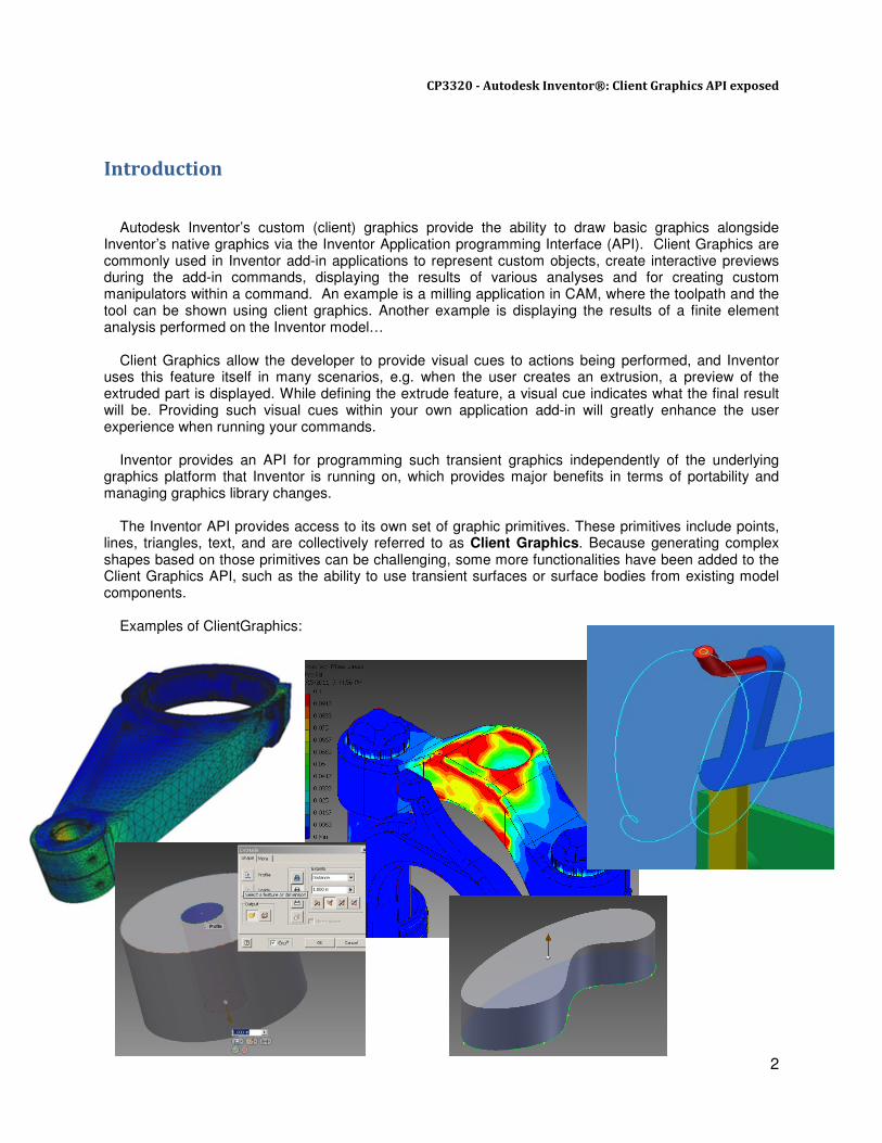
Autodesk Inventor’s custom (client) graphics provide the ability to draw basic graphics alongside Inventor’s native graphics via the Inventor Application programming Interface (API). Client Graphics are commonly used in Inventor add-in applications to represent custom objects, create interactive previews during the add-in commands, displaying the results of various analyses and for creating custom manipulators within a command. An example is a milling application in CAM, where the toolpath and the tool can be shown using client graphics. Another example is displaying the results of a finite element analysis performed on the Inventor model… Client Graphics allow the developer to provide visual cues to actions being performed, and Inventor uses this feature itself in many scenarios, e.g. when the user creates an extrusion, a preview of the extruded part is displayed. While defining the extrude feature, a visual cue indicates what the final result will be. Providing such visual cues within your own application add-in will greatly enhance the user experience when running your commands. Inventor provides an API for programming such transient graphics independently of the underlying graphics platform that Inventor is running on, which provides major benefits in terms of portability and managing graphics library changes. The Inventor API provides access to its own set of graphic primitives. These primitives include points, lines, triangles, text, and are collectively referred to as Client Graphics. Because generating complex shapes based on those primitives can be challenging, some more functionalities have been added to the Client Graphics API, such as the ability to use transient surfaces or surface bodies from existing model components. Examples of ClientGraphics:
CP3320 - Autodesk Inventor®: Client Graphics API exposed
3
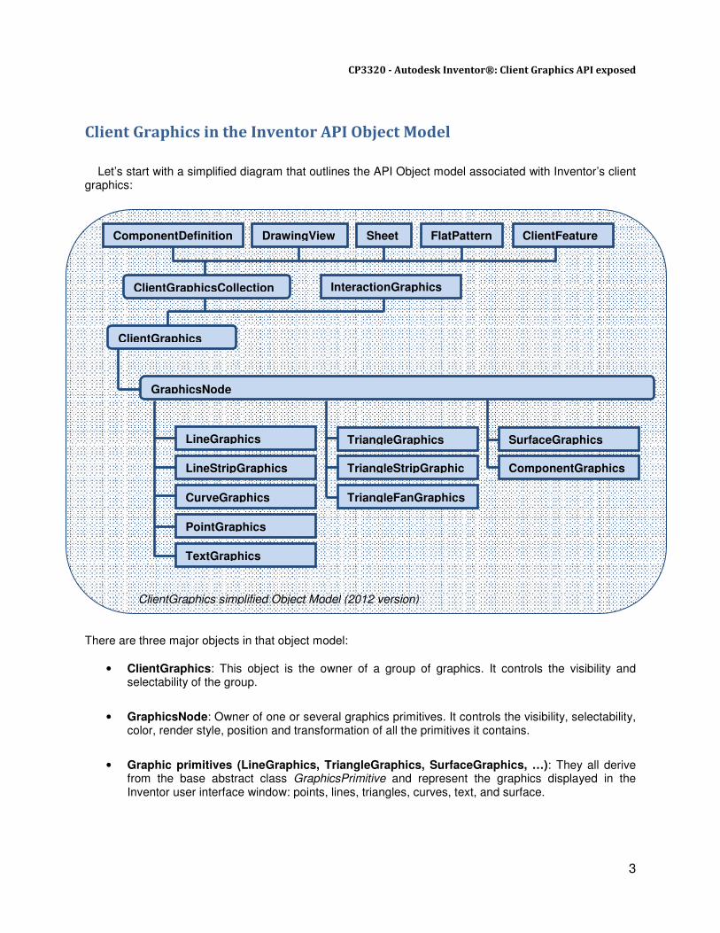
Client Graphics in the Inventor API Object Model Let’s start with a simplified diagram that outlines the API Object model associated with Inventor’s client graphics:
There are three major objects in that object model:
• ClientGraphics: This object is the owner of a group of graphics. It controls the visibility and selectability of the group.
• GraphicsNode: Owner of one or several graphics primitives. It controls the visibility, selectability, color, render style, position and transformation of all the primitives it contains.
• Graphic primitives (LineGraphics, TriangleGraphics, SurfaceGraphics, …): They all derive from the base abstract class GraphicsPrimitive and represent the graphics displayed in the Inventor user interface window: points, lines, triangles, curves, text, and surface.
ComponentDefinition DrawingView Sheet FlatPattern
TriangleFanGraphics CurveGraphics
LineStripGraphics
PointGraphics
InteractionGraphics
ComponentGraphics
SurfaceGraphics LineGraphics TriangleGraphics
TriangleStripGraphic
TextGraphics
ClientGraphicsCollection
ClientGraphics
GraphicsNode
ClientFeature
ClientGraphics simplified Object Model (2012 version)

CP3320 - Autodesk Inventor®: Client Graphics API exposed
4
Types of Client Graphics ClientGraphics can be distinguished in two main categories, depending on the object they are invoked
from.
Regular Client Graphics
These types of client graphics are associated with an Inventor document. They are transient unless
associated with a client feature (we will see more about this in the section “Storing Graphics”), which
means they are not retained by the document when the document is closed. They can be associated with
the following API objects: PartComponentDefinition, AssemblyComponentDefinition, FlatPattern,
DrawingView, Sheet, ClientFeatureDefinition.
Each of the previous objects can have more than one ClientGraphics object associated with it. Each
ClientGraphics object can have many graphics nodes and each node can contain any number and any
type of GraphicsPrimitive.
Interaction Client Graphics
This type of client graphics is available when using InteractionEvents. They would be used typically to
display temporary or preview graphics while running a command and will be automatically deleted as the
InteractionEvents terminates, that is when the command is finished or cancelled. They are always
transient. Like regular ClientGraphics, the InteractionEvents object can have any number of nodes and
graphics primitives.
Basic Properties
A GraphicsNode object has some properties to control the default behavior of all primitives it contains.
Here are the most important:
Render Style
By default, the linetype, lineweight and color of the graphics primitives owned by a node will use the
settings of the RenderStyle until they are overridden by LineType, LineWeight, Color (for Curve and
SurfaceGraphics), and ColorSet (for Line, Triangle and TriangleFan graphics).
Visibility
The Visible property controls and overwrites the visibility of all primitives owned by the node
The VisibleInViews returns an object containing the Views that this graphics node is visible in. If there
are no views in the list, the node is visible in all views.
The VisibleInActiveEditObject is a Boolean that gets or sets whether this graphics node is visible when
the containing object is not the active edit object.
Selectable
Specifies whether the GraphicsNode object can be selected when the Select command is running in
Inventor.
Transformation
A 4x4 transformation matrix that can be used to get or set the transformation of the GraphicsNode.
When transforming a node, each graphic primitive it contains will be transformed accordingly.
CP3320 - Autodesk Inventor®: Client Graphics API exposed
5
Graphics Data in the Inventor API Object Model
In Inventor most client graphics will need to be defined using two different types of objects: one of the
graphic primitive that we introduced in the previous section and potentially some graphics data. The
graphics data is the low-level information that can be used to define primitives, for example that will be
coordinates of the start and end points of a LineGraphics. An advantage of separating the data from the
primitives is that same data can be re-used by many different graphics primitives.
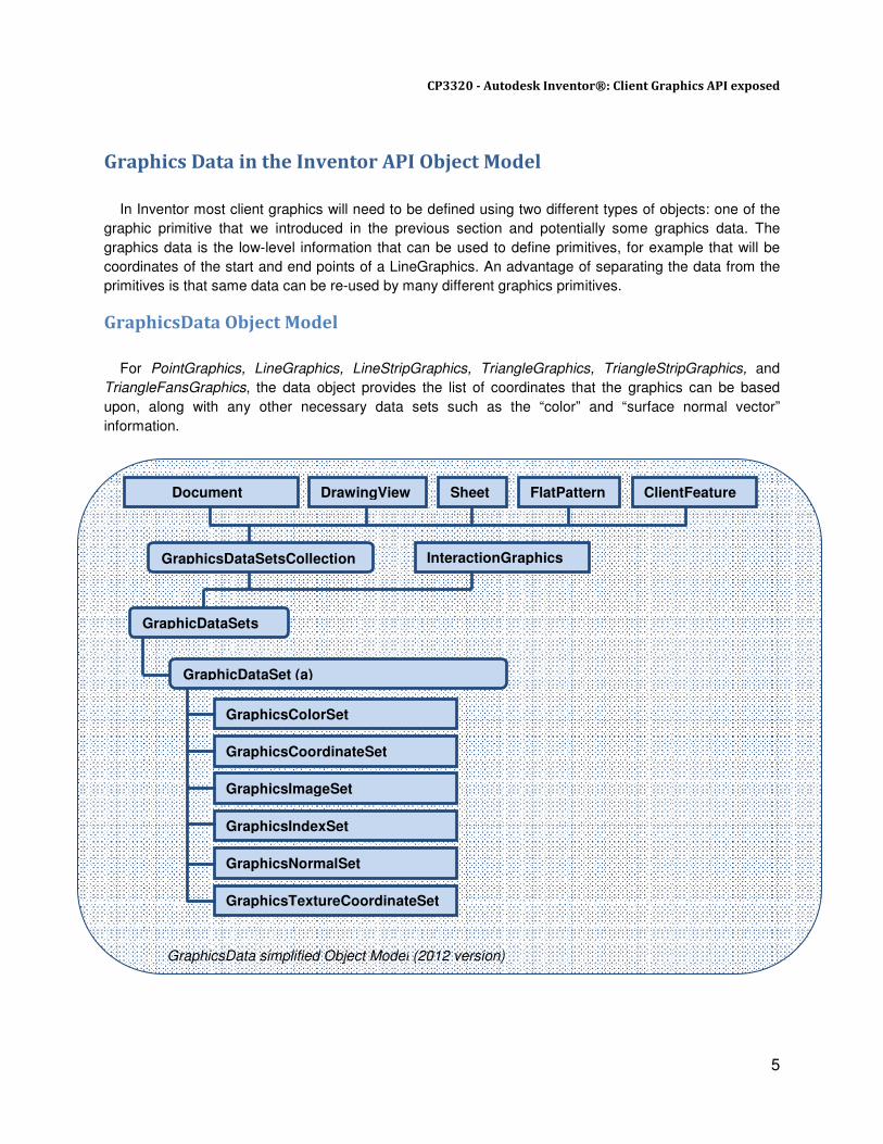
GraphicsData Object Model
For PointGraphics, LineGraphics, LineStripGraphics, TriangleGraphics, TriangleStripGraphics, and
TriangleFansGraphics, the data object provides the list of coordinates that the graphics can be based
upon, along with any other necessary data sets such as the “color” and “surface normal vector”
information.
Document DrawingView Sheet FlatPattern
GraphicsIndexSet
GraphicsImageSet
GraphicsNormalSet
InteractionGraphics
GraphicsCoordinateSet
GraphicsColorSet
GraphicsTextureCoordinateSet
GraphicsDataSetsCollection
GraphicDataSets
GraphicDataSet (a)
ClientFeature
GraphicsData simplified Object Model (2012 version)

CP3320 - Autodesk Inventor®: Client Graphics API exposed
6
The GraphicsData object model is very similar to the one we presented earlier for ClientGraphics. The data set collection can be obtained from various sources: either Document, DrawingView, Sheet, FlatPattern or ClientFeatureDefinition. And the InteractionEvents also exposes its own GraphicsDataSets that will be cleared as the interaction terminates. A GraphicsDataSetsCollection can contain one or several GraphicsDataSets, each of them containing as many GraphicsDataSet as needed. The GraphicsDataSet being the base abstract class, it derives into the following types:
• GraphicsCoordinateSet: The coordinates used to specify the vertices for the graphic sets.
• GraphicsColorSet: A set of colors used by a graphic set. It overrides any other color information assigned to the set. Colors in the color set can be bound to the entire graphic set, each individual primitive in the set (e.g. each triangle in a triangle strip), or each vertex in the set (i.e. interpolated color).
• GraphicsNormalSet: Contains a list of normal vectors (which can be used to define how the lighting is calculated for the triangles).
• GraphicsIndexSet: Each graphics primitive can access this set to more efficiently use an associated
coordinate or color.
• GraphicsImageSet:Contains a list of images to be used by PointGraphics using custom images.
• GraphicsTextureCoordinateSet: contains a list of coordinate values to be used by graphic primitives to define their texture coordinates.
Subsidiary Objects
Other objects that you might need at some point during your quest for creating ClientGraphics are:
• TransientGeometry
The TransientGeometry object is a utility object you use to create various mathematical transient
objects such as points, curves, surfaces, vectors, and matrices. In association with client graphics,
the ability to create different types of curves is useful because you can use these as input to define
CurveGraphics.
• TransientBrep
The TransientBRep object is used to create transient surfaces and solids. These can be used to
create SurfaceGraphics.

CP3320 - Autodesk Inventor®: Client Graphics API exposed
7
General procedure to draw ClientGraphics
Creation of ClientGraphics follows the general procedure below:
1. Get the ClientGraphicsCollection from the graphics source, which can be:
� The ComponentDefinition in a Part or an Assembly document
� A DrawingView or a Sheet in a Drawing document
� ClientFeatureDefinition if the graphics are to be attached with a ClientFeature
� InteractionEvents for Interaction Client Graphics
2. Add a new ClientGraphics object to ClientGraphicsCollection, or use an existing one.
3. Add to the ClientGraphics group as many GraphicsNodes as you need
4. If graphics data is needed, get the GraphicsDataSetsCollection object from graphics source, which will be most likely the same object than the one used to obtain ClientGraphicsCollection
5. Add a GraphicsDataSets object and create the graphics data depending on the type of data you are going to need to define your primitives: coordinates, indices, images, and so on… Other type of transient data can also be generated, such as curves and surface bodies, which are not part of a GraphicsDataSets.
6. Create new GraphicsPrimitive objects to the node(s) using one of the GraphicsNode.Addxxx method.
7. Assign graphics data to the primitives created previously and set primitive properties if needed
8. Update the view(s)
Let’s take a look at a first sample code to see concretely how the previous workflow is applied when
using the Inventor API.
The following Sample is written in C# and illustrates how to create a LineGraphics inside a
PartDocument. We are assuming here that the document does not contain any existing ClientGraphics or
GraphicsData, so for simplicity no error checking or exception handling is performed.
CP3320 - Autodesk Inventor®: Client Graphics API exposed
8
// Demonstrates creation of a simple LineGraphics primitive in a PartDocument
static public void LineGraphicsDemo(PartDocument doc)
{
// ClientId, can be any string
// Typically use instead current add-in GUID
string clientId = "{Add-in Guid}";
// Add a new graphics group.
// This will fail if a group with same name already exists
ClientGraphics graphics =
doc.ComponentDefinition.ClientGraphicsCollection.Add(clientId);
// Add a new graphic node, with Id=1.
// Id needs to be unique within graphics group
GraphicsNode node = graphics.AddNode(1);
// Add new data set
GraphicsDataSets dataSets =
doc.GraphicsDataSetsCollection.Add(clientId);
// Add new coordinate set
// Id needs to be unique within data set
GraphicsCoordinateSet coordSet = dataSets.CreateCoordinateSet(1);
// Fill up coordinates
// Point1: [0.0, 0.0, 0.0]
// Point2: [1.0, 1.0, 1.0]
double[] coords = new double[]
{
0.0, 0.0, 0.0,
1.0, 1.0, 1.0
};
coordSet.PutCoordinates(ref coords);
// Create new GraphicsPrimitive
LineGraphics lineGraphPrimitive = node.AddLineGraphics();
lineGraphPrimitive.LineWeight = 5;
// Set coordinates
lineGraphPrimitive.CoordinateSet = coordSet;
// Update the current view, so we see the graphics
doc.Views[1].Update();
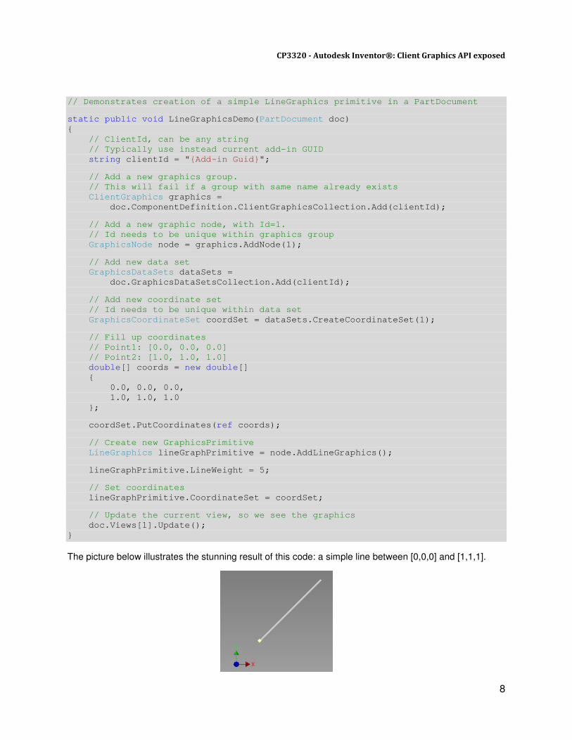
} The picture below illustrates the stunning result of this code: a simple line between [0,0,0] and [1,1,1].
CP3320 - Autodesk Inventor®: Client Graphics API exposed
9
Graphic Primitives exposed
In this section we take a look in more detail at the GraphicsPrimitives. However before going through
each type of primitive, let’s expose a few important properties that are common to all of them:
BurnThrough
This specifies whether or not graphics are always visible even if they are blocked by other objects.
DepthPriority
Property that allows you to specify a display priority to the graphics. This is used in the cases where entities are coincident. The entities with the higher priority will render on top of lower priority entities.
SetViewSpaceAnchor
This will anchor the primitive in view space so that the graphics will display in one fixed position, no
matter how the view changes.
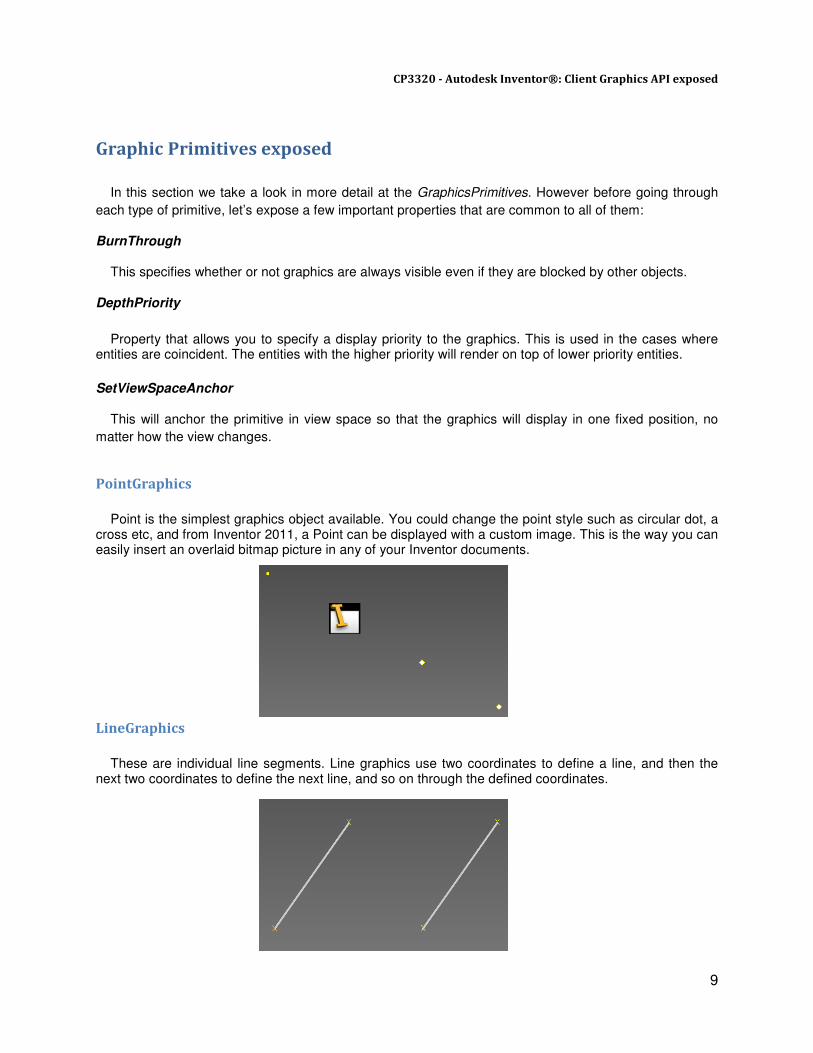
PointGraphics
Point is the simplest graphics object available. You could change the point style such as circular dot, a cross etc, and from Inventor 2011, a Point can be displayed with a custom image. This is the way you can easily insert an overlaid bitmap picture in any of your Inventor documents.
LineGraphics
These are individual line segments. Line graphics use two coordinates to define a line, and then the next two coordinates to define the next line, and so on through the defined coordinates.
CP3320 - Autodesk Inventor®: Client Graphics API exposed
10
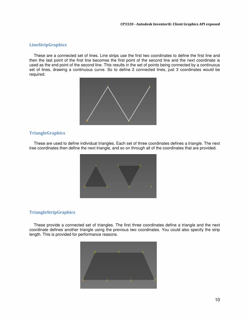
LineStripGraphics
These are a connected set of lines. Line strips use the first two coordinates to define the first line and then the last point of the first line becomes the first point of the second line and the next coordinate is used as the end point of the second line. This results in the set of points being connected by a continuous set of lines, drawing a continuous curve. So to define 2 connected lines, just 3 coordinates would be required. TriangleGraphics
These are used to define individual triangles. Each set of three coordinates defines a triangle. The next tree coordinates then define the next triangle, and so on through all of the coordinates that are provided.
TriangleStripGraphics These provide a connected set of triangles. The first three coordinates define a triangle and the next coordinate defines another triangle using the previous two coordinates. You could also specify the strip length. This is provided for performance reasons.
CP3320 - Autodesk Inventor®: Client Graphics API exposed
11
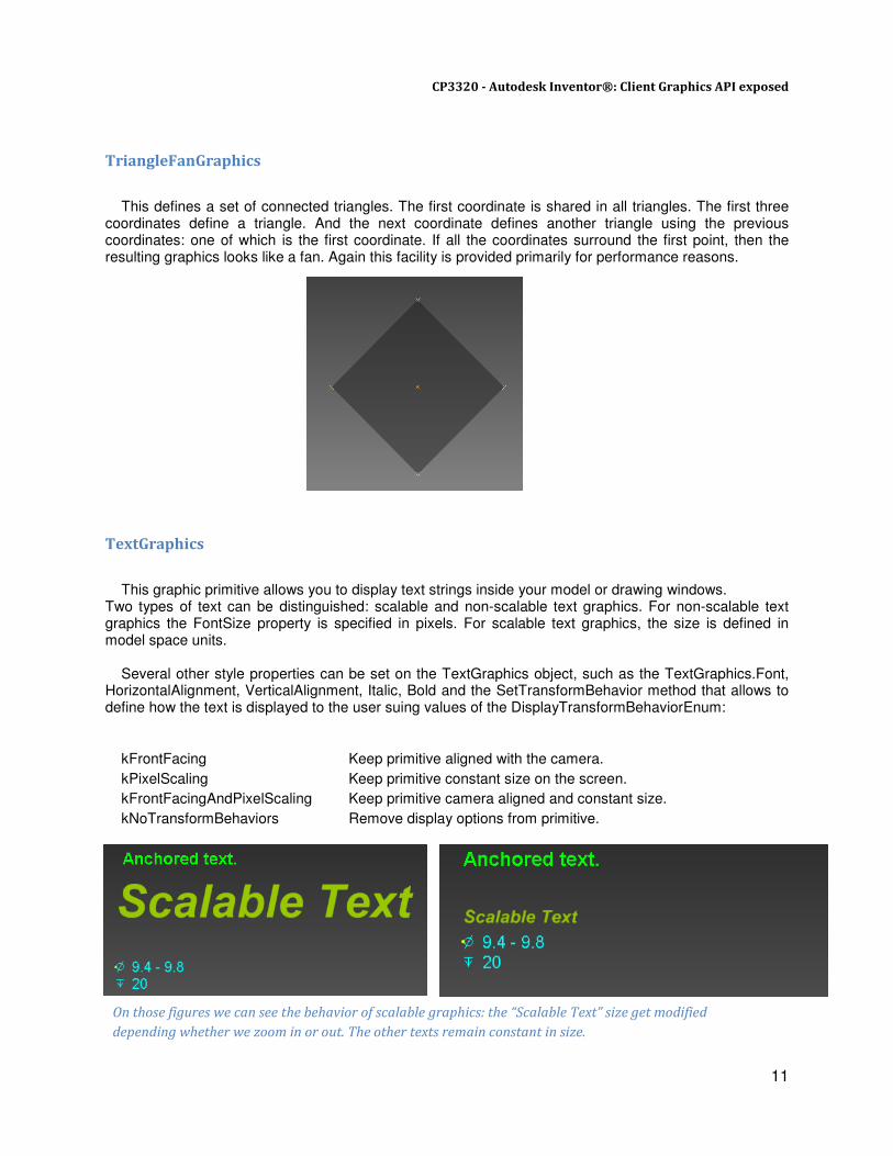
TriangleFanGraphics This defines a set of connected triangles. The first coordinate is shared in all triangles. The first three coordinates define a triangle. And the next coordinate defines another triangle using the previous coordinates: one of which is the first coordinate. If all the coordinates surround the first point, then the resulting graphics looks like a fan. Again this facility is provided primarily for performance reasons. TextGraphics This graphic primitive allows you to display text strings inside your model or drawing windows. Two types of text can be distinguished: scalable and non-scalable text graphics. For non-scalable text graphics the FontSize property is specified in pixels. For scalable text graphics, the size is defined in model space units. Several other style properties can be set on the TextGraphics object, such as the TextGraphics.Font, HorizontalAlignment, VerticalAlignment, Italic, Bold and the SetTransformBehavior method that allows to define how the text is displayed to the user suing values of the DisplayTransformBehaviorEnum:
kFrontFacing Keep primitive aligned with the camera.
kPixelScaling Keep primitive constant size on the screen.
kFrontFacingAndPixelScaling Keep primitive camera aligned and constant size.
kNoTransformBehaviors Remove display options from primitive.
On those figures we can see the behavior of scalable graphics: the “Scalable Text” size get modified
depending whether we zoom in or out. The other texts remain constant in size.
CP3320 - Autodesk Inventor®: Client Graphics API exposed
12
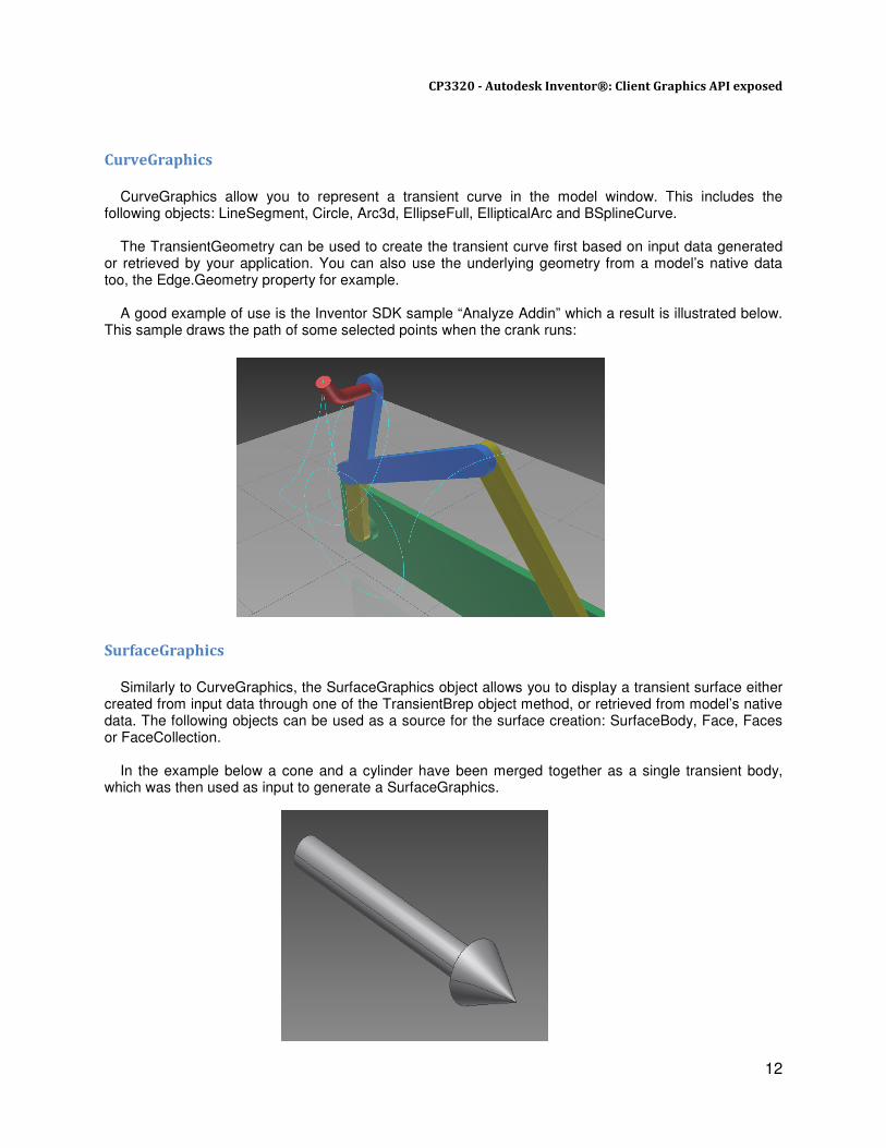
CurveGraphics
CurveGraphics allow you to represent a transient curve in the model window. This includes the following objects: LineSegment, Circle, Arc3d, EllipseFull, EllipticalArc and BSplineCurve.
The TransientGeometry can be used to create the transient curve first based on input data generated or retrieved by your application. You can also use the underlying geometry from a model’s native data too, the Edge.Geometry property for example. A good example of use is the Inventor SDK sample “Analyze Addin” which a result is illustrated below. This sample draws the path of some selected points when the crank runs:
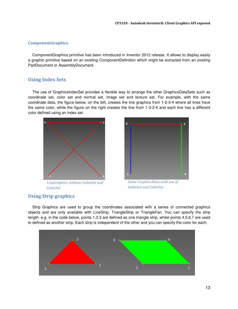
SurfaceGraphics
Similarly to CurveGraphics, the SurfaceGraphics object allows you to display a transient surface either created from input data through one of the TransientBrep object method, or retrieved from model’s native data. The following objects can be used as a source for the surface creation: SurfaceBody, Face, Faces or FaceCollection. In the example below a cone and a cylinder have been merged together as a single transient body, which was then used as input to generate a SurfaceGraphics.
CP3320 - Autodesk Inventor®: Client Graphics API exposed
13
ComponentGraphics
ComponentGraphics primitive has been introduced in Inventor 2012 release. It allows to display easily
a graphic primitive based on an existing ComponentDefinition which might be extracted from an existing
PartDocument or AssemblyDocument.
Using Index Sets
The use of GraphicsIndexSet provides a flexible way to arrange the other GraphicsDataSets such as
coordinate set, color set and normal set, image set and texture set. For example, with the same
coordinate data, the figure below, on the left, creates the line graphics from 1-2-3-4 where all lines have
the same color, while the figure on the right creates the line from 1-3-2-4 and each line has a different
color defined using an index set.
Using Strip graphics
Strip Graphics are used to group the coordinates associated with a series of connected graphics
objects and are only available with LineStrip, TriangleStrip or TriangleFan. You can specify the strip
length. e.g. in the code below, points 1,2,3 are defined as one triangle strip, whilst points 4,5,6,7 are used
to defined as another strip. Each strip is independent of the other and you can specify the color for each.
LineGraphics without IndexSet and
ColorSet
Same GraphicsData with use of
IndexSet and ColorSet

CP3320 - Autodesk Inventor®: Client Graphics API exposed
14
Below is a code sample that illustrates how to use GraphicsIndexSet to index coordinates and colors
for our ClientGraphics lines shown in the pictures above:
GraphicsNode node = graphics.AddNode(graphics.Count + 1);
GraphicsCoordinateSet coordSet =
dataSets.CreateCoordinateSet(dataSets.Count + 1);
double[] coords = new double[]{
0.0, 0.0, 0.0, //point 1
1.0, 1.0, 0.0, //point 2
0.0, 1.0, 0.0, //point 3
1.0, 0.0, 0.0 //point 4
};
coordSet.PutCoordinates(ref coords);
LineGraphics primitive = node.AddLineGraphics();
primitive.LineWeight = 5;
//Create Coordinate Index Set
GraphicsIndexSet indexSetCoords =
dataSets.CreateIndexSet(dataSets.Count + 1);
indexSetCoords.Add(1, 1); //from point 1
indexSetCoords.Add(2, 3); //connect to point 3
indexSetCoords.Add(3, 3); //from point 3
indexSetCoords.Add(4, 2); //connect to point 2
indexSetCoords.Add(5, 2); //from point 2
indexSetCoords.Add(6, 4); //connect to point 4
//Create the color set with two colors
GraphicsColorSet colorSet =
dataSets.CreateColorSet(dataSets.Count + 1);
colorSet.Add(1, 250, 0, 0);
colorSet.Add(2, 0, 250, 0);
colorSet.Add(2, 0, 0, 250);
//Create the index set for color
GraphicsIndexSet indexSetColors =
dataSets.CreateIndexSet(dataSets.Count + 1);
indexSetColors.Add(1, 3); //line 1 uses color 3
indexSetColors.Add(2, 1); //line 2 uses color 1
indexSetColors.Add(3, 2); //line 3 uses color 3
primitive.CoordinateSet = coordSet;
primitive.CoordinateIndexSet = indexSetCoords;
primitive.ColorSet = colorSet;
primitive.ColorIndexSet = indexSetColors;
primitive.ColorBinding = ColorBindingEnum.kPerItemColors;
CP3320 - Autodesk Inventor®: Client Graphics API exposed
15
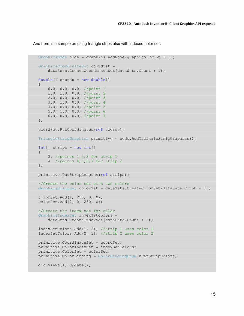
And here is a sample on using triangle strips also with indexed color set:
GraphicsNode node = graphics.AddNode(graphics.Count + 1);
GraphicsCoordinateSet coordSet =
dataSets.CreateCoordinateSet(dataSets.Count + 1);
double[] coords = new double[]
{
0.0, 0.0, 0.0, //point 1
1.0, 1.0, 0.0, //point 2
2.0, 0.0, 0.0, //point 3
3.0, 1.0, 0.0, //point 4
4.0, 0.0, 0.0, //point 5
5.0, 1.0, 0.0, //point 6
6.0, 0.0, 0.0, //point 7
};
coordSet.PutCoordinates(ref coords);
TriangleStripGraphics primitive = node.AddTriangleStripGraphics();
int[] strips = new int[]
{
3, //points 1,2,3 for strip 1
4 //points 4,5,6,7 for strip 2
};
primitive.PutStripLengths(ref strips);
//Create the color set with two colors
GraphicsColorSet colorSet = dataSets.CreateColorSet(dataSets.Count + 1);
colorSet.Add(1, 250, 0, 0);
colorSet.Add(2, 0, 250, 0);
//Create the index set for color
GraphicsIndexSet indexSetColors =
dataSets.CreateIndexSet(dataSets.Count + 1);
indexSetColors.Add(1, 2); //strip 1 uses color 1
indexSetColors.Add(2, 1); //strip 2 uses color 2
primitive.CoordinateSet = coordSet;
primitive.ColorIndexSet = indexSetColors;
primitive.ColorSet = colorSet;
primitive.ColorBinding = ColorBindingEnum.kPerStripColors;
doc.Views[1].Update();
CP3320 - Autodesk Inventor®: Client Graphics API exposed
16
Using Model Native Data
Most scenarios where Client Graphics are required are based on the models native geometry. It is
quite easy to get the data using Inventor API objects. e.g. SurfaceBody, Face, Edge, Vertex in Part or
Assembly Documents, and DrawingCurve in drawing documents. The code below creates and transforms
a surface using an existing SurfaceBody from the model.
It is also possible to obtain a coordinate data set from the existing SurfaceBody, Edge or Face objects
using the CalculateStrokes method. You determine the tolerance (the number of points you need) by first
calling GetExistingStrokeTolerances. You may need to do this multiple times in order to assess the
average tolerance for the model. Similarly, obtain triangular facets from a SurfaceBody or Face using
CalculateFacets.
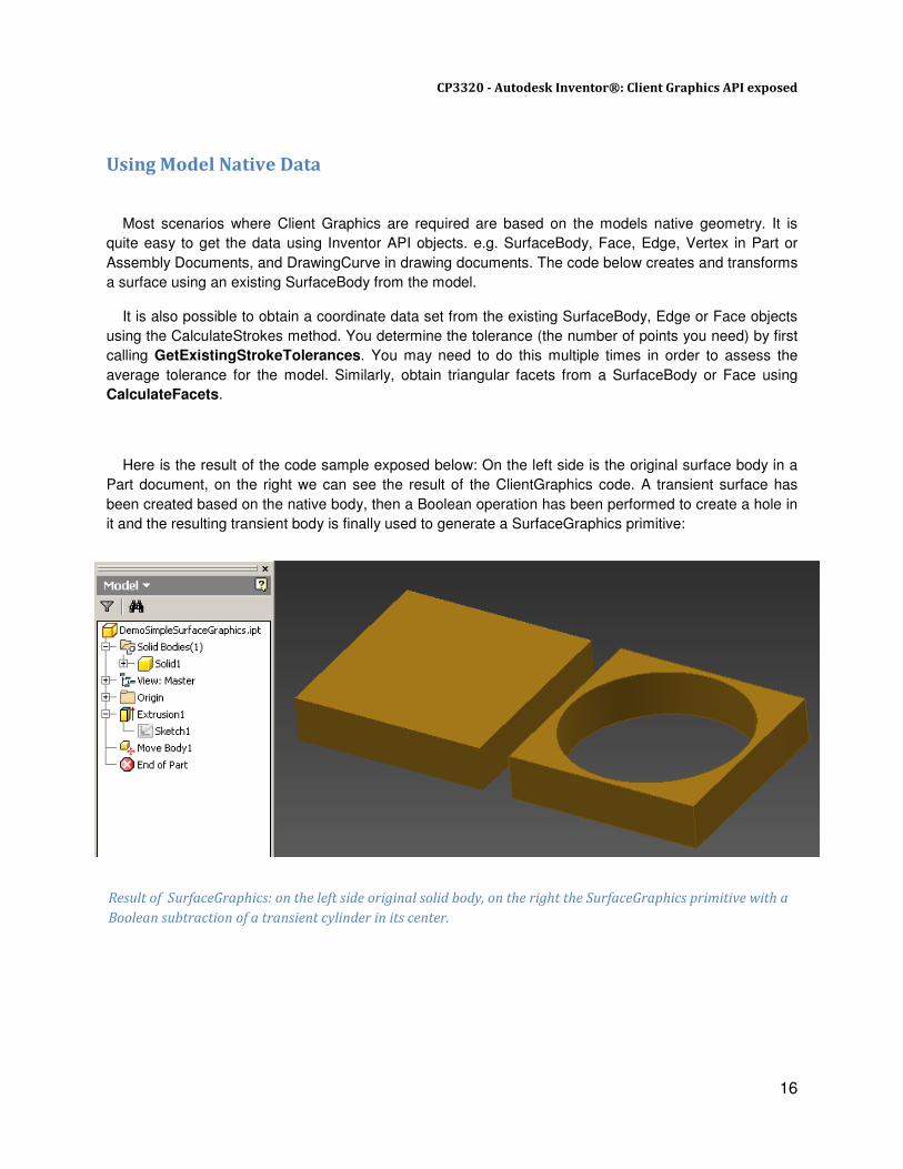
Here is the result of the code sample exposed below: On the left side is the original surface body in a
Part document, on the right we can see the result of the ClientGraphics code. A transient surface has
been created based on the native body, then a Boolean operation has been performed to create a hole in
it and the resulting transient body is finally used to generate a SurfaceGraphics primitive:
Result of SurfaceGraphics: on the left side original solid body, on the right the SurfaceGraphics primitive with a
Boolean subtraction of a transient cylinder in its center.

CP3320 - Autodesk Inventor®: Client Graphics API exposed
17
Here is the code sample used to generate the result illustrated by the picture above. We assume here
the active document is a Part with at least 1 Surface Body in it:
//Store utility objects
TransientGeometry geom =
AdnInventorUtilities.InventorApplication.TransientGeometry;
TransientBRep brep =
AdnInventorUtilities.InventorApplication.TransientBRep;
GraphicsNode node = graphics.AddNode(graphics.Count + 1);
//We will work on the first surface body in our document
SurfaceBody nativeBody = doc.ComponentDefinition.SurfaceBodies[1];
//Create a transient copy of the native body to work on it
SurfaceBody body = brep.Copy(nativeBody);
//Compute bottom/top points based on body bounding box
Point bottom = geom.CreatePoint(
(nativeBody.RangeBox.MinPoint.X + nativeBody.RangeBox.MaxPoint.X)/2,
(nativeBody.RangeBox.MinPoint.Y + nativeBody.RangeBox.MaxPoint.Y)/2,
nativeBody.RangeBox.MinPoint.Z);
Point top = geom.CreatePoint(
(nativeBody.RangeBox.MinPoint.X + nativeBody.RangeBox.MaxPoint.X)/2,
(nativeBody.RangeBox.MinPoint.Y + nativeBody.RangeBox.MaxPoint.Y)/2,
nativeBody.RangeBox.MaxPoint.Z);
//Create transient tool body, a cylinder of radius 2.0 cm
SurfaceBody tool =
brep.CreateSolidCylinderCone(bottom, top, 2.0, 2.0, 2.0, null);
//Do boolean operation between transient bodies to remove cylinder
brep.DoBoolean(body, tool, BooleanTypeEnum.kBooleanTypeDifference);
//Add SurfaceGraphics primitive
SurfaceGraphics primitive = node.AddSurfaceGraphics(body);
//Copy render style of native body if any
StyleSourceTypeEnum source;
RenderStyle style = nativeBody.GetRenderStyle(out source);
node.RenderStyle = style;
//Hide native body
nativeBody.Visible = false;
doc.Views[1].Update();
CP3320 - Autodesk Inventor®: Client Graphics API exposed
18
Interaction Client Graphics
Interaction Client Graphics operate in a similar manner to regular ClientGraphics, except that it all
happens in the context of InteractionEvents. ClientGraphics created via InteractionGraphics are optimized
for this environment, and run much faster than transacted graphics. They are well suited to real-time
feedback during a command. As the client graphics are displayed in the context of an InteractionEvents
object, they can take advantage of mouse movement information, selection information, and any other
events supported by the InteractionEvents objects. Typically the MouseMove event can be used to
dynamically update preview graphics as the user is moving the mouse or hovering over certain entities in
the model window.These graphics are automatically removed once the associated InteractionEvents
object stops.
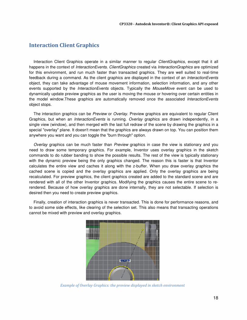
The interaction graphics can be Preview or Overlay. Preview graphics are equivalent to regular Client
Graphics, but when an InteractionEvents is running. Overlay graphics are drawn independently, in a
single view (window), and then merged with the last full redraw of the scene by drawing the graphics in a
special "overlay" plane. It doesn't mean that the graphics are always drawn on top. You can position them
anywhere you want and you can toggle the "burn through" option.
Overlay graphics can be much faster than Preview graphics in case the view is stationary and you
need to draw some temporary graphics. For example, Inventor uses overlay graphics in the sketch
commands to do rubber banding to show the possible results. The rest of the view is typically stationary
with the dynamic preview being the only graphics changed. The reason this is faster is that Inventor
calculates the entire view and caches it along with the z-buffer. When you draw overlay graphics the
cached scene is copied and the overlay graphics are applied. Only the overlay graphics are being
recalculated. For preview graphics, the client graphics created are added to the standard scene and are
rendered with all of the other Inventor graphics. Modifying the graphics causes the entire scene to re-
rendered. Because of how overlay graphics are done internally, they are not selectable. If selection is
desired then you need to create preview graphics.
Finally, creation of interaction graphics is never transacted. This is done for performance reasons, and
to avoid some side effects, like clearing of the selection set. This also means that transacting operations
cannot be mixed with preview and overlay graphics. Example of Overlay Graphics: the preview displayed in sketch environment

CP3320 - Autodesk Inventor®: Client Graphics API exposed
19
Here is one of the simplest implementation of InteractionEvents controlling InteractionGraphics. The
code creates a TriangleGraphics and uses mouse move events to update the 3rd
vertex of the triangle as
user moves the mouse pointer in the model window:
class SimpleInteraction{
static TriangleGraphics _triangleGraph = null;
static InteractionEvents _interactionEvents;
static MouseEvents _mouseEvents;
public static void Demo(){
Inventor.Application InvApp = AdnInventorUtilities.InventorApplication;
_interactionEvents = InvApp.CommandManager.CreateInteractionEvents();
_mouseEvents = _interactionEvents.MouseEvents;
//Enable mouse move. This is disabled by default for performance reasons
_mouseEvents.MouseMoveEnabled = true;
//Listen to OnMouseMove event
_mouseEvents.OnMouseMove +=
new MouseEventsSink_OnMouseMoveEventHandler(MouseEvents_OnMouseMove);
_interactionEvents.StatusBarText = "Select triangle vertex: ";
//Retrieve InteractionGraphics
InteractionGraphics ig = _interactionEvents.InteractionGraphics;
//Create new node and add Triangle primitive to it
GraphicsNode node = ig.OverlayClientGraphics.AddNode(1);
_triangleGraph = node.AddTriangleGraphics();
GraphicsCoordinateSet coordSet = ig.GraphicsDataSets.CreateCoordinateSet(1);
double[] coords = new double[]{
0.0, 0.0, 0.0, //vertex 1
5.0, 0.0, 0.0, //vertex 2
2.5, 5.0, 0.0 //vertex 3
};
coordSet.PutCoordinates(ref coords);
_triangleGraph.CoordinateSet = coordSet;
_interactionEvents.Start();
}
static void MouseEvents_OnMouseMove(MouseButtonEnum Button,
ShiftStateEnum ShiftKeys, Inventor.Point ModelPosition,
Point2d ViewPosition, Inventor.View View)
{
//Retrieve coordinates and update the 3rd vextex of our graphics triangle
_triangleGraph.CoordinateSet[3] = ModelPosition;
//Update active view to see result
_interactionEvents.InteractionGraphics.UpdateOverlayGraphics(
AdnInventorUtilities.InventorApplication.ActiveView);
}
}
CP3320 - Autodesk Inventor®: Client Graphics API exposed
20
Storing Client Graphics
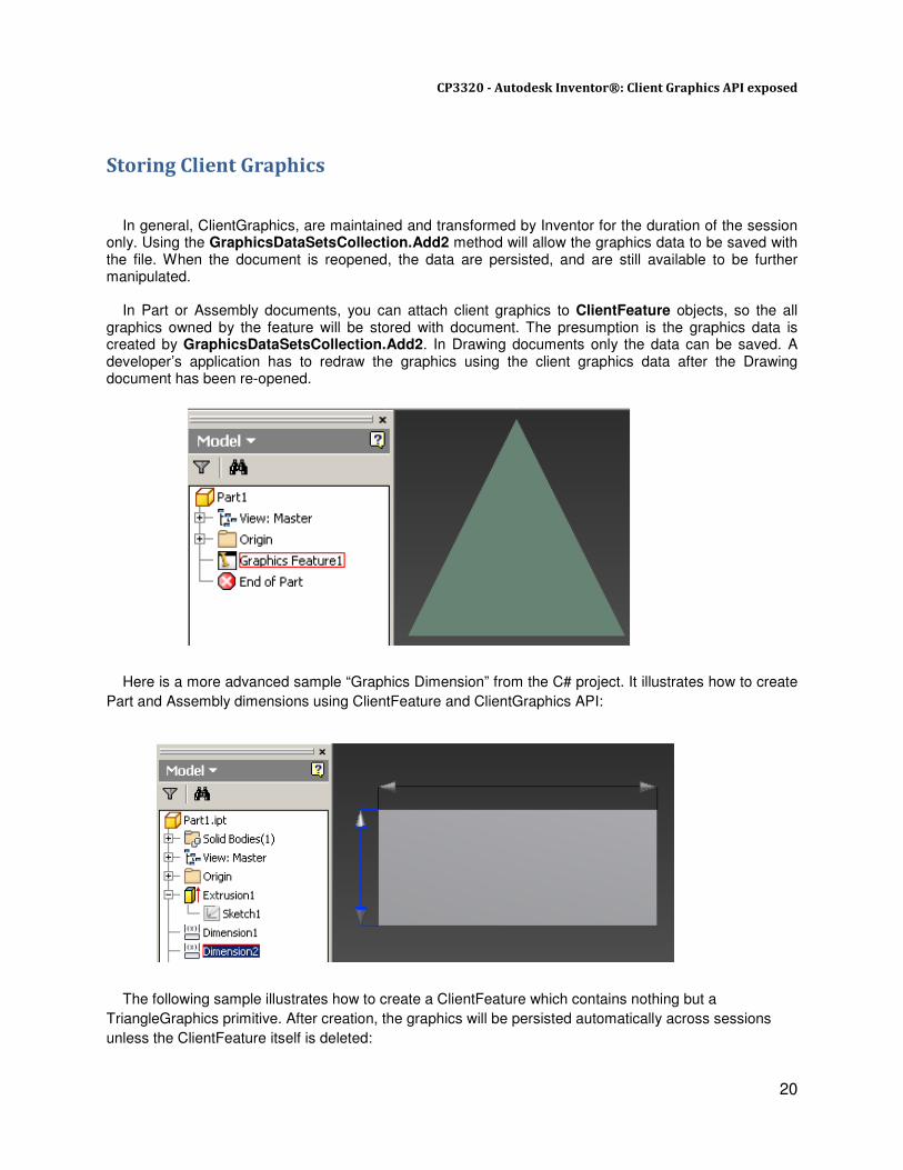
In general, ClientGraphics, are maintained and transformed by Inventor for the duration of the session only. Using the GraphicsDataSetsCollection.Add2 method will allow the graphics data to be saved with the file. When the document is reopened, the data are persisted, and are still available to be further manipulated. In Part or Assembly documents, you can attach client graphics to ClientFeature objects, so the all graphics owned by the feature will be stored with document. The presumption is the graphics data is created by GraphicsDataSetsCollection.Add2. In Drawing documents only the data can be saved. A developer’s application has to redraw the graphics using the client graphics data after the Drawing document has been re-opened.
Here is a more advanced sample “Graphics Dimension” from the C# project. It illustrates how to create
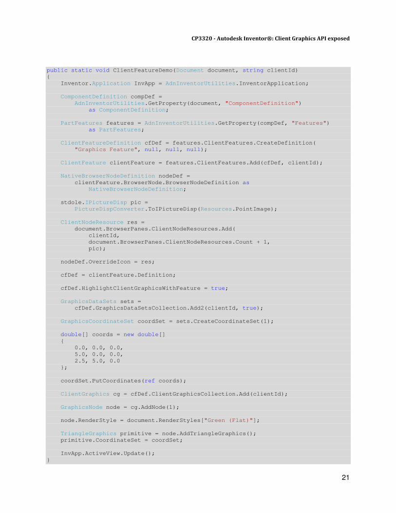
Part and Assembly dimensions using ClientFeature and ClientGraphics API: The following sample illustrates how to create a ClientFeature which contains nothing but a
TriangleGraphics primitive. After creation, the graphics will be persisted automatically across sessions
unless the ClientFeature itself is deleted:
CP3320 - Autodesk Inventor®: Client Graphics API exposed
21
public static void ClientFeatureDemo(Document document, string clientId)
{
Inventor.Application InvApp = AdnInventorUtilities.InventorApplication;
ComponentDefinition compDef =
AdnInventorUtilities.GetProperty(document, "ComponentDefinition")
as ComponentDefinition;
PartFeatures features = AdnInventorUtilities.GetProperty(compDef, "Features")
as PartFeatures;
ClientFeatureDefinition cfDef = features.ClientFeatures.CreateDefinition(
"Graphics Feature", null, null, null);
ClientFeature clientFeature = features.ClientFeatures.Add(cfDef, clientId);
NativeBrowserNodeDefinition nodeDef =
clientFeature.BrowserNode.BrowserNodeDefinition as
NativeBrowserNodeDefinition;
stdole.IPictureDisp pic =
PictureDispConverter.ToIPictureDisp(Resources.PointImage);
ClientNodeResource res =
document.BrowserPanes.ClientNodeResources.Add(
clientId,
document.BrowserPanes.ClientNodeResources.Count + 1,
pic);
nodeDef.OverrideIcon = res;
cfDef = clientFeature.Definition;
cfDef.HighlightClientGraphicsWithFeature = true;
GraphicsDataSets sets =
cfDef.GraphicsDataSetsCollection.Add2(clientId, true);
GraphicsCoordinateSet coordSet = sets.CreateCoordinateSet(1);
double[] coords = new double[]
{
0.0, 0.0, 0.0,
5.0, 0.0, 0.0,
2.5, 5.0, 0.0
};
coordSet.PutCoordinates(ref coords);
ClientGraphics cg = cfDef.ClientGraphicsCollection.Add(clientId);
GraphicsNode node = cg.AddNode(1);
node.RenderStyle = document.RenderStyles["Green (Flat)"];
TriangleGraphics primitive = node.AddTriangleGraphics();
primitive.CoordinateSet = coordSet;
InvApp.ActiveView.Update();
}
CP3320 - Autodesk Inventor®: Client Graphics API exposed
22
Using Non-transacted ClientGraphics Until Inventor 2011, the only non-transacted client graphics that developers could use with the API
were preview and overlay graphics obtained from the InteractionEvents. That meant that the only way to
have a fast rendering of client graphics was to start InteractionEvents, which could be undesirable in
certain workflows.
Inventor 2012 now offers the ability to work with non-transacted graphics which provide the exact same
functionalities than regular client graphics, but much faster.
Their use is pretty straightforward: you would need to call the “AddNonTransacting” method on the
“GraphicsDataSetsCollection” and “ClientGraphicsCollection” instead of the regular “Add” method.
This will generate a non-transacted set which exposes the exact same methods and properties that its
transacted counterpart.
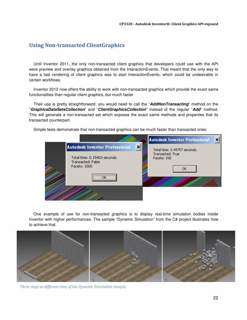
Simple tests demonstrate that non-transacted graphics can be much faster than transacted ones:
One example of use for non-transacted graphics is to display real-time simulation bodies inside
Inventor with higher performances. The sample “Dynamic Simulation” from the C# project illustrates how
to achieve that.
Miscellaneous Functionalities
Slicing
This provides the functionality to slice a graphic node based on the input planes and optionally caps the
sliced end.
Three steps at different time of the Dynamic Simulation Sample.
CP3320 - Autodesk Inventor®: Client Graphics API exposed
23
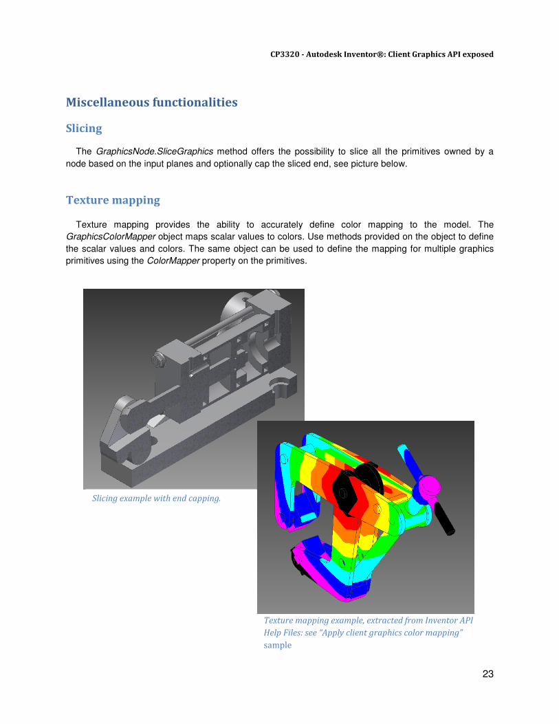
Miscellaneous functionalities
Slicing
The GraphicsNode.SliceGraphics method offers the possibility to slice all the primitives owned by a
node based on the input planes and optionally cap the sliced end, see picture below.
Texture mapping
Texture mapping provides the ability to accurately define color mapping to the model. The
GraphicsColorMapper object maps scalar values to colors. Use methods provided on the object to define
the scalar values and colors. The same object can be used to define the mapping for multiple graphics
primitives using the ColorMapper property on the primitives.
Slicing example with end capping.
Texture mapping example, extracted from Inventor API
Help Files: see “Apply client graphics color mapping”
sample

CP3320 - Autodesk Inventor®: Client Graphics API exposed
24
Additional resources for Inventor developers
• A good starting point for all Inventor developers is the resources listed on the Inventor Developer
Center: www.autodesk.com/developinventor.
These include:
� Training material, recorded presentations, and Add-ins Wizards.
� My First Inventor Plug-in, a self-paced tutorial project for newbie’s and power users who want
to get up and running with Inventor programming:
http://usa.autodesk.com/adsk/servlet/index?siteID=123112&id=17324828
� Information on joining the Autodesk Developer Network: www.autodesk.com/joinadn
� Information on training classes and webcasts: www.autodesk.com/apitraining
� Links to the Autodesk discussion groups: www.autodesk.com/discussion.
• Many of the concepts you need to understand ClientGraphics are included in the Inventor API SDK
documentation. You will also find there many VB.Net and C# samples.
• Brian Ekins’ blog, the Inventor API main designer: http://modthemachine.typepad.com.
• If you’re an ADN partner, there is a wealth of Autodesk API information on the members-only ADN
website: http://adn.autodesk.com
� ADN members can ask unlimited API questions through our DevHelp Online interface
• Watch out for our regular ADN DevLab events. DevLab is a programmers’ workshop (free to ADN
and non-ADN members) where you can come and discuss your Autodesk programming problems
with the ADN DevTech team.
• The following link points to the Webcast Recordings Archive, where you will find, among many other,
the Introductory Inventor API (Modules 1-10) in English and also some further resources in various
languages: http://www.adskconsulting.com/adn/cs/api_course_webcast_archive.php

CP3320 - Autodesk Inventor®: Client Graphics API exposed
25
Samples Description:
The zip file provided with this class contains a C# project with extensive samples about the various
ClientGraphics functionalities, and also VB.Net and VBA projects.
• ClientGraphicsDemoAU
This is a C# addin, which can be accessed from the Inventor Ribbon bar, Tab “Tools”. It contains
several modules, each of them illustrates one functionality of the ClientGraphics API:
� BasicPrimitives.cs: A series of simple demos for various graphic primitives.
� BasicLine.cs: Displays a LineGraphics between two vertices selected by the user on the model.
� ClientFeatureGraphics.cs: Displays a TriangleGraphics attached to a ClientFeature. The graphics
stored inside the ClientFeature are persisted across sessions.
� Component.cs: A more advanced example illustrating the use of ComponentGraphics and MouseEvents. The user can select a part or assembly to insert inside the active part, a Non-Parametric base feature is then created.
� CurveGraphic.cs: Displays a CurveGraphics based on an edge selected by the user on the
model.
� DrawingGraphics.cs: Illutrates use of ClientGraphics in Drawing Sheet, using Interaction and
MouseEvents to draw a moving symbol on the drawing.
� DynamicSimulationControl.cs: Performed dynamic simulation inside an assembly using transacted or non-transacted ClientGraphics. The dynamic simulation engine is powered by Bullet, a professional free 3D Game Multiphysics Library, visit http://bulletphysics.org for more details about Bullet.
� GraphicsDimension.cs: Illutrates use of ClientGraphics to store ClientGraphics based dimensions
working in Part or Assembly documents.
� InteractionLineStrip.cs: An interaction example using a LinStripsGraphics and MouseEvents.
� LineStrip.cs: Displays a LineStripGraphics between three vertices selected by the user on the
model.
� SimpleInteraction.cs: A simple interaction example using a TriangleGraphics and MouseEvents.
� SimpleInteractionMng.cs: A simple interaction example using a LineGraphics and MouseEvents.
� SliceGraphics.cs: Illustrates use of graphic node slicing functionality.

CP3320 - Autodesk Inventor®: Client Graphics API exposed
26
• Clientgraphics.ivb
It contains VBA code, and can be loaded into the Inventor VBA environment via the VBA IDE. There
are 3 modules and 1 class:
� modBasicSample: These macros demonstrate the creation of graphics primitives, using an index set, strip graphics and using native model geometry as a basis for generating client graphics. You can run the macros from the VBA IDE or from the Inventor user interface directly from the tools menu; Tools�Macros.
� modInteractionGraphics: These macros demonstrate client graphics of when associated with the InteractionEvents object.
� modAdvancedFun: This macro demonstrates some advanced client graphics functionality.
� clsDragComponent: A utility class that is used with the InteractionGraphics sample.
Each macro is commented to help explain what it is doing, and how the task is accomplished.
• VBNet_ClientGraphics
This is a VB.Net addin, which is accessed from the Inventor Ribbon Bar:
� ClientGraphicsSetup.msi: This is the installer. After installing, open a Part, Assembly or Drawing document, then run the command from the user interface as follows (Select Tools�Client Graphics). This displays a dialog with a series of buttons that run each of the individual samples. They illustrate various techniques related to client graphics creation. Selecting an option in the CComBox will draw the relevant graphics primitive in the current view.
� Source code: The source code can be loaded and run in Microsoft’s Visual Studio development environment.
Thank you!
The Authors: Philippe Leefsma & Xiaodong Liang.