Embed Size (px)
Citation preview
Atmel SmartConnect
ATWILC3000 Bluetooth Porting Guide
USER GUIDE
Introduction
This user guide describes the software deliveries of Atmel® ATWILC3000 Wi-Fi®/Bluetooth® combo chip
and the features it provides tested by the software.
Deliveries are tested against SAMA5D4 running Android KitKat 4.4.
Atmel-42562A-ATWILC3000-Porting-Guide_UserGuide_032016
ATWILC3000 Bluetooth Porting Guide [USER GUIDE] Atmel-42562A-ATWILC3000-Porting-Guide_UserGuide_032016 2
2
Table of Contents
1 HCI Interface ................................................................................................................. 4
1.1 Introduction ............................................................................................................................................ 4 1.2 HCI Command Packet ......................................................................................................................... 4
1.3 HCI Event Packet ................................................................................................................................. 5
2 Vendor Specific HCI Commands ................................................................................ 6
2.1 Update UART Parameters Command ................................................................................................ 6
2.2 Change BD Address ............................................................................................................................ 6
2.3 Write Memory ....................................................................................................................................... 6
2.4 Vendor Specific Reset......................................................................................................................... 6
2.5 Read Register ...................................................................................................................................... 6
3 Firmware Download ..................................................................................................... 7
3.1 Using UART ......................................................................................................................................... 7
3.1.1 Detecting if Firmware is Downloaded or Not........................................................................ 7
3.1.2 Firmware is Already Downloaded ......................................................................................... 7
3.1.3 Start Firmware Download....................................................................................................... 7
4 ATMEL EVALUATION BOARD/KIT IMPORTANT NOTICE AND DISCLAIMER ........ 11
5 Revision History ........................................................................................................ 12
ATWILC3000 Bluetooth Porting Guide [USER GUIDE] Atmel-42562A-ATWILC3000-Porting-Guide_UserGuide_032016
3
3
Icon Key Identifiers
Useful Tips and Techniques
Delivers Contextual Information About a Specific Topic
Note to Quality and Performance
Objectives to be Completed
Actions to be Executed Out of the Target
The Expected Result of an Assignment Step
Procedure Which Can Result in Minor Equipment Damage
Procedure With Potential Equipment Damage
Procedure With Imminent Equipment Destruction
ATWILC3000 Bluetooth Porting Guide [USER GUIDE] Atmel-42562A-ATWILC3000-Porting-Guide_UserGuide_032016 4
4
1 HCI Interface
Bluetooth (BT) uses standard HCI commands for communication between the host and BT controller. The
HCI commands are defined in the Bluetooth Specification Version 4.0.
1.1 Introduction
There are four kinds of HCI packets that can be sent via the UART Transport Layer:
HCI Command Packet
HCI Event Packet
HCI ACL Data Packet
HCI Synchronous Data Packet
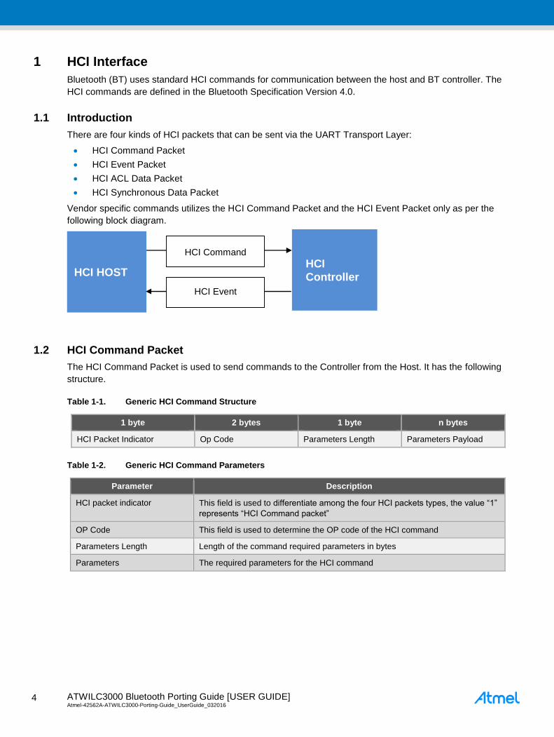
Vendor specific commands utilizes the HCI Command Packet and the HCI Event Packet only as per the
following block diagram.
1.2 HCI Command Packet
The HCI Command Packet is used to send commands to the Controller from the Host. It has the following
structure.
Table 1-1. Generic HCI Command Structure
1 byte 2 bytes 1 byte n bytes
HCI Packet Indicator Op Code Parameters Length Parameters Payload
Table 1-2. Generic HCI Command Parameters
Parameter Description
HCI packet indicator This field is used to differentiate among the four HCI packets types, the value “1”
represents “HCI Command packet”
OP Code This field is used to determine the OP code of the HCI command
Parameters Length Length of the command required parameters in bytes
Parameters The required parameters for the HCI command
HCI HOST HCI
Controller
HCI Command
HCI Event
ATWILC3000 Bluetooth Porting Guide [USER GUIDE] Atmel-42562A-ATWILC3000-Porting-Guide_UserGuide_032016
5
5
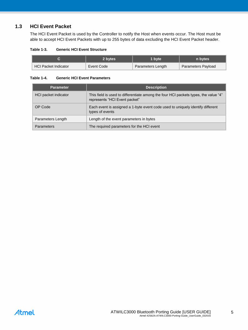
1.3 HCI Event Packet
The HCI Event Packet is used by the Controller to notify the Host when events occur. The Host must be
able to accept HCI Event Packets with up to 255 bytes of data excluding the HCI Event Packet header.
Table 1-3. Generic HCI Event Structure
C 2 bytes 1 byte n bytes
HCI Packet Indicator Event Code Parameters Length Parameters Payload
Table 1-4. Generic HCI Event Parameters
Parameter Description
HCI packet indicator This field is used to differentiate among the four HCI packets types, the value “4”
represents “HCI Event packet”
OP Code Each event is assigned a 1-byte event code used to uniquely identify different
types of events
Parameters Length Length of the event parameters in bytes
Parameters The required parameters for the HCI event
ATWILC3000 Bluetooth Porting Guide [USER GUIDE] Atmel-42562A-ATWILC3000-Porting-Guide_UserGuide_032016 6
6
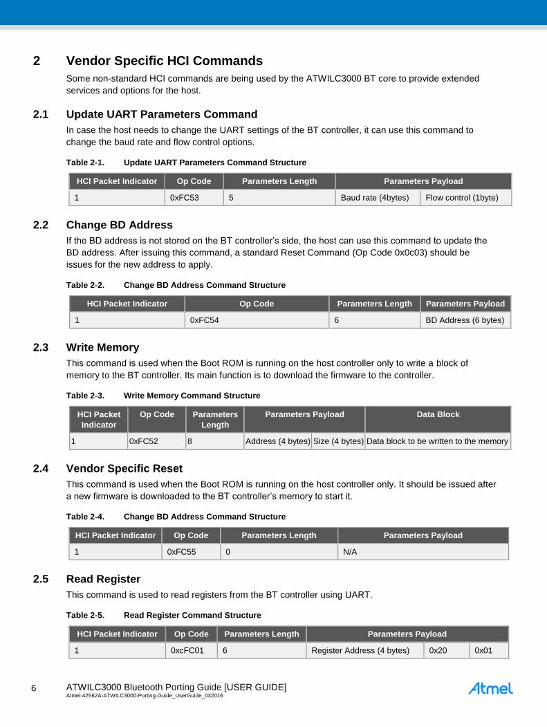
2 Vendor Specific HCI Commands
Some non-standard HCI commands are being used by the ATWILC3000 BT core to provide extended
services and options for the host.
2.1 Update UART Parameters Command
In case the host needs to change the UART settings of the BT controller, it can use this command to
change the baud rate and flow control options.
Table 2-1. Update UART Parameters Command Structure
HCI Packet Indicator Op Code Parameters Length Parameters Payload
1 0xFC53 5 Baud rate (4bytes) Flow control (1byte)
2.2 Change BD Address
If the BD address is not stored on the BT controller’s side, the host can use this command to update the
BD address. After issuing this command, a standard Reset Command (Op Code 0x0c03) should be
issues for the new address to apply.
Table 2-2. Change BD Address Command Structure
HCI Packet Indicator Op Code Parameters Length Parameters Payload
1 0xFC54 6 BD Address (6 bytes)
2.3 Write Memory
This command is used when the Boot ROM is running on the host controller only to write a block of
memory to the BT controller. Its main function is to download the firmware to the controller.
Table 2-3. Write Memory Command Structure
HCI Packet
Indicator
Op Code Parameters
Length
Parameters Payload Data Block
1 0xFC52 8 Address (4 bytes) Size (4 bytes) Data block to be written to the memory
2.4 Vendor Specific Reset
This command is used when the Boot ROM is running on the host controller only. It should be issued after
a new firmware is downloaded to the BT controller’s memory to start it.
Table 2-4. Change BD Address Command Structure
HCI Packet Indicator Op Code Parameters Length Parameters Payload
1 0xFC55 0 N/A
2.5 Read Register
This command is used to read registers from the BT controller using UART.
Table 2-5. Read Register Command Structure
HCI Packet Indicator Op Code Parameters Length Parameters Payload
1 0xcFC01 6 Register Address (4 bytes) 0x20 0x01
ATWILC3000 Bluetooth Porting Guide [USER GUIDE] Atmel-42562A-ATWILC3000-Porting-Guide_UserGuide_032016
7
7
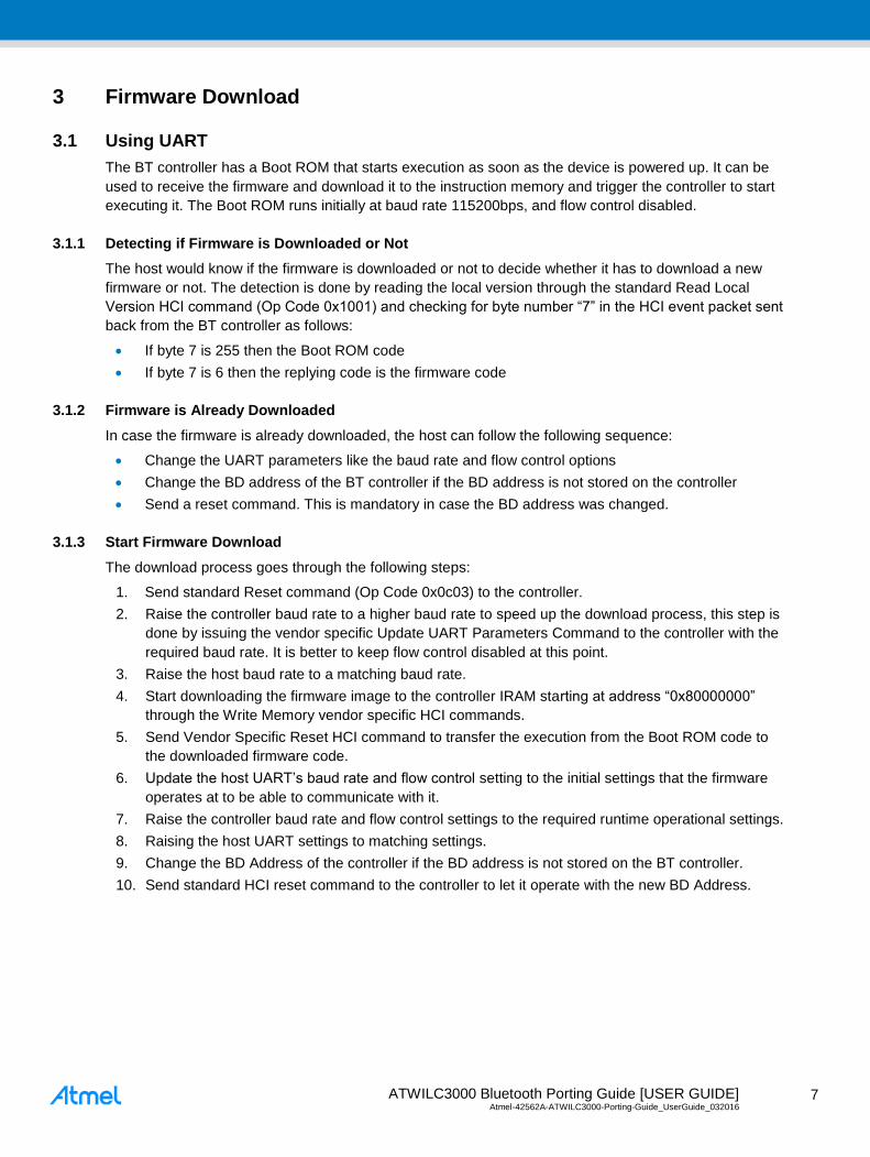
3 Firmware Download
3.1 Using UART
The BT controller has a Boot ROM that starts execution as soon as the device is powered up. It can be
used to receive the firmware and download it to the instruction memory and trigger the controller to start
executing it. The Boot ROM runs initially at baud rate 115200bps, and flow control disabled.
3.1.1 Detecting if Firmware is Downloaded or Not
The host would know if the firmware is downloaded or not to decide whether it has to download a new
firmware or not. The detection is done by reading the local version through the standard Read Local
Version HCI command (Op Code 0x1001) and checking for byte number “7” in the HCI event packet sent
back from the BT controller as follows:
If byte 7 is 255 then the Boot ROM code
If byte 7 is 6 then the replying code is the firmware code
3.1.2 Firmware is Already Downloaded
In case the firmware is already downloaded, the host can follow the following sequence:
Change the UART parameters like the baud rate and flow control options
Change the BD address of the BT controller if the BD address is not stored on the controller
Send a reset command. This is mandatory in case the BD address was changed.
3.1.3 Start Firmware Download
The download process goes through the following steps:
1. Send standard Reset command (Op Code 0x0c03) to the controller.
2. Raise the controller baud rate to a higher baud rate to speed up the download process, this step is
done by issuing the vendor specific Update UART Parameters Command to the controller with the
required baud rate. It is better to keep flow control disabled at this point.
3. Raise the host baud rate to a matching baud rate.
4. Start downloading the firmware image to the controller IRAM starting at address “0x80000000”
through the Write Memory vendor specific HCI commands.
5. Send Vendor Specific Reset HCI command to transfer the execution from the Boot ROM code to
the downloaded firmware code.
6. Update the host UART’s baud rate and flow control setting to the initial settings that the firmware
operates at to be able to communicate with it.
7. Raise the controller baud rate and flow control settings to the required runtime operational settings.
8. Raising the host UART settings to matching settings.
9. Change the BD Address of the controller if the BD address is not stored on the BT controller.
10. Send standard HCI reset command to the controller to let it operate with the new BD Address.
ATWILC3000 Bluetooth Porting Guide [USER GUIDE] Atmel-42562A-ATWILC3000-Porting-Guide_UserGuide_032016 8
8
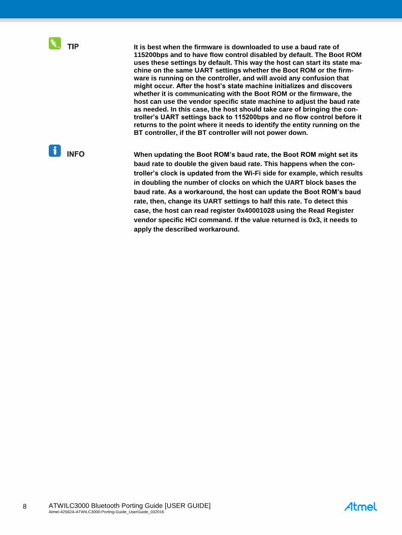
It is best when the firmware is downloaded to use a baud rate of 115200bps and to have flow control disabled by default. The Boot ROM uses these settings by default. This way the host can start its state ma-chine on the same UART settings whether the Boot ROM or the firm-ware is running on the controller, and will avoid any confusion that might occur. After the host’s state machine initializes and discovers whether it is communicating with the Boot ROM or the firmware, the host can use the vendor specific state machine to adjust the baud rate as needed. In this case, the host should take care of bringing the con-troller’s UART settings back to 115200bps and no flow control before it returns to the point where it needs to identify the entity running on the BT controller, if the BT controller will not power down.
When updating the Boot ROM’s baud rate, the Boot ROM might set its
baud rate to double the given baud rate. This happens when the con-
troller’s clock is updated from the Wi-Fi side for example, which results
in doubling the number of clocks on which the UART block bases the
baud rate. As a workaround, the host can update the Boot ROM’s baud
rate, then, change its UART settings to half this rate. To detect this
case, the host can read register 0x40001028 using the Read Register
vendor specific HCI command. If the value returned is 0x3, it needs to
apply the described workaround.
ATWILC3000 Bluetooth Porting Guide [USER GUIDE] Atmel-42562A-ATWILC3000-Porting-Guide_UserGuide_032016
9
9
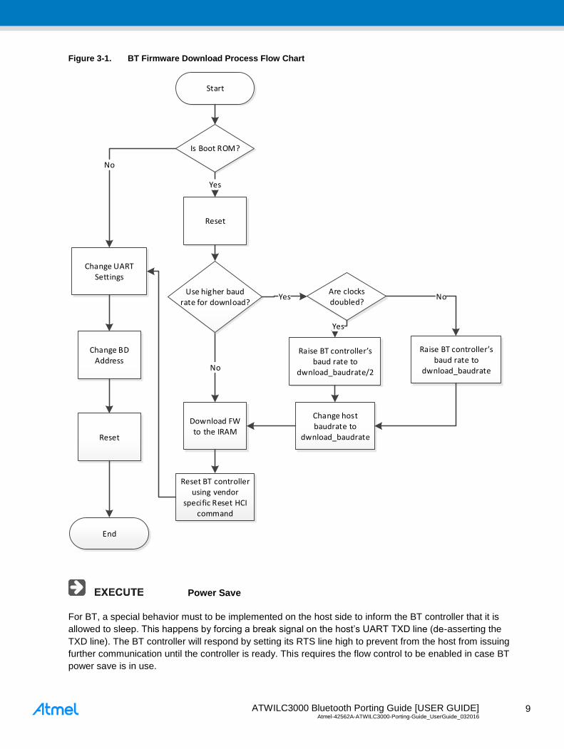
Figure 3-1. BT Firmware Download Process Flow Chart
Is Boot ROM?
Change BD Address
No
Reset
Change UART Settings
End
Start
Reset
Yes
Download FW to the IRAM
No
Use higher baud rate for download?
YesAre clocks doubled?
Raise BT controller’s baud rate to
dwnload_baudrate/2
Raise BT controller’s baud rate to
dwnload_baudrate
Yes
No
Change host baudrate to
dwnload_baudrate
Reset BT controller using vendor
specific Reset HCI command
Power Save
For BT, a special behavior must to be implemented on the host side to inform the BT controller that it is
allowed to sleep. This happens by forcing a break signal on the host’s UART TXD line (de-asserting the
TXD line). The BT controller will respond by setting its RTS line high to prevent from the host from issuing
further communication until the controller is ready. This requires the flow control to be enabled in case BT
power save is in use.
ATWILC3000 Bluetooth Porting Guide [USER GUIDE] Atmel-42562A-ATWILC3000-Porting-Guide_UserGuide_032016 1
0
10
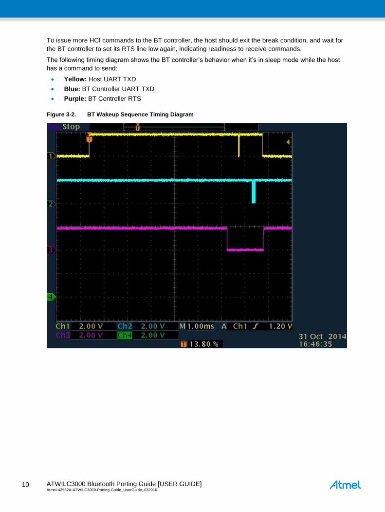
To issue more HCI commands to the BT controller, the host should exit the break condition, and wait for
the BT controller to set its RTS line low again, indicating readiness to receive commands.
The following timing diagram shows the BT controller’s behavior when it’s in sleep mode while the host
has a command to send:
Yellow: Host UART TXD
Blue: BT Controller UART TXD
Purple: BT Controller RTS
Figure 3-2. BT Wakeup Sequence Timing Diagram
ATWILC3000 Bluetooth Porting Guide [USER GUIDE] Atmel-42562A-ATWILC3000-Porting-Guide_UserGuide_032016
1
1
11
4 ATMEL EVALUATION BOARD/KIT IMPORTANT NOTICE AND
DISCLAIMER
This evaluation board/kit is intended for user's internal development and evaluation purposes only. It is
not a finished product and may not comply with technical or legal requirements that are applicable to
finished products, including, without limitation, directives or regulations relating to electromagnetic
compatibility, recycling (WEEE), FCC, CE or UL. Atmel is providing this evaluation board/kit “AS IS”
without any warranties or indemnities. The user assumes all responsibility and liability for handling and
use of the evaluation board/kit including, without limitation, the responsibility to take any and all
appropriate precautions with regard to electrostatic discharge and other technical issues. User indemnifies
Atmel from any claim arising from user's handling or use of this evaluation board/kit. Except for the limited
purpose of internal development and evaluation as specified above, no license, express or implied, by
estoppel or otherwise, to any Atmel intellectual property right is granted hereunder. ATMEL SHALL NOT
BE LIABLE FOR ANY INDIRECT, SPECIAL, INCIDENTAL, OR CONSEQUENTIAL DAMGES RELATING
TO USE OF THIS EVALUATION BOARD/KIT.
ATMEL CORPORATION
1600 Technology Drive
San Jose, CA 95110
USA
ATWILC3000 Bluetooth Porting Guide [USER GUIDE] Atmel-42562A-ATWILC3000-Porting-Guide_UserGuide_032016 1
2
12
5 Revision History
Doc Rev. Date Comments
42562A 03/2016 Initial document release.

ATWILC3000 Bluetooth Porting Guide [USER GUIDE] Atmel-42562A-ATWILC3000-Porting-Guide_UserGuide_032016
1
3
13
Atmel Corporation 1600 Technology Drive, San Jose, CA 95110 USA T: (+1)(408) 441.0311 F: (+1)(408) 436.4200 │ www.atmel.com
© 2016 Atmel Corporation. / Rev.: Atmel-42562A-ATWILC3000-Porting-Guide_UserGuide_032016. Atmel®, Atmel logo and combinations thereof, Enabling Unlimited Possibilities®, and others are registered trademarks or trademarks of Atmel Corporation in U.S. and other countries. ARM®, ARM Connected® logo, and others are the registered trademarks or trademarks of ARM Ltd. Other terms and product names may be trademarks of others. DISCLAIMER: The information in this document is provided in connection with Atmel products. No license, express or implied, b y estoppel or otherwise, to any intellectual property right is granted by this document or in connection with the sale of Atmel products. EXCEPT AS SET FORTH IN THE ATMEL TERMS AND CONDITIONS OF SALES LOCATED ON THE ATMEL WEBSITE, ATMEL ASSUMES NO LIABILITY WHATSOEVER AND DISCLAIMS ANY EXPRESS, IMPLIED OR STATUTORY WARRANTY RELATING TO ITS PRODUCTS
INCLUDING, BUT NOT LIMITED TO, THE IMPLIED WARRANTY OF MERCHANTABILITY, FITNESS FOR A PARTICULAR PURPOSE, OR NON-INFRINGEMENT. IN NO EVENT SHALL ATMEL BE LIABLE FOR ANY DIRECT, INDIRECT, CONSEQUENTIAL, PUNITIVE, SPECIAL OR INCIDENTAL DAMAGES (INCLUDING, WITHOUT LI MITATION, DAMAGES FOR LOSS AND PROFITS, BUSINESS INTERRUPTION, OR LOSS OF INFORMATION) ARISING OUT OF THE USE OR INABILITY TO USE THIS DOCUMENT, EVEN IF ATMEL
HAS BEEN ADVISED OF THE POSSIBILITY OF SUCH DAMAGES. Atmel makes no representations or warranties with respect to the accurac y or completeness of the contents of this document and reserves the right to make changes to specifications and products descriptions at any time without notice. Atmel does not make any commitment to update the information contained herein. Unless specifically provided otherwise, Atmel products are not suitable for, and shall not be used in, automotive applications. Atmel produc ts are not intended,
authorized, or warranted for use as components in applications intended to support or sustain life.
SAFETY-CRITICAL, MILITARY, AND AUTOMOTIVE APPLICATIONS DISCLAIMER: Atmel products are not designed for and will not be used in connect ion with any applications where the failure of such products would reasonably be expected to result in significant personal injury or death (“Safety-Critical Applications”) without an Atmel officer's specific written consent. Safety-Critical Applications include, without limitation, life support devices and systems, equipment or systems for the operation o f nuclear facilities and weapons systems. Atmel
products are not designed nor intended for use in military or aerospace applications or environments unless specifically desi gnated by Atmel as military-grade. Atmel products are not
designed nor intended for use in automotive applications unless specifically designated by Atmel as automotive-grade.