Embed Size (px)
Citation preview

ATV38_58.book Page 1 Mardi, 11. février 2003 11:15 11
Guide d'exploitationUser's manual
Altivar 38-58-58F
Variables internes de communicationInternal Communication Variables
1
FRA
NÇ
AIS
ENG
LISH
Altivar 38-58-58F
Variables internes de communication Page 2
Internal Communication Variables Page 42
ATV38_58.book Page 1 Mardi, 11. février 2003 11:15 11

2
FRA
NÇ
AIS
Malgré tout le soin apporté à l'élaboration de ce document, Schneider Electric SA ne donne aucune garantiesur les informations qu'il contient, et ne peut être tenu responsable ni des erreurs qu'il pourrait comporter, nides dommages qui pourraient résulter de son utilisation ou de son application.
Les produits présentés dans ce document sont à tout moment susceptibles d'évolutions quant à leurscaractéristiques de présentation et de fonctionnement. Leur description ne peut en aucun cas revêtir unaspect contractuel.
Depuis le début de sa commercialisation, l'Altivar 58 a bénéficié de fonctionnalités supplémentaires, et dela création des ATV 58F et ATV 38. Ce document tient compte de ces adjonctions. Son utilisation avec lespremiers appareils reste opérationnelle mais dans ce cas, il est normal d'y voir décrits des paramètresabsents de ces variateurs.
ATV38_58.book Page 2 Mardi, 11. février 2003 11:15 11

3
FRA
NÇ
AIS
Sommaire
Généralités ________________________________________________________________________ 4Modes de commande _______________________________________________________________ 5Contrôle et pilotage en mode LIGNE ____________________________________________________ 8Variables de l'Altivar ________________________________________________________________ 12
Paramètres de configuration générale _____________________________________ 12Paramètres de configuration de l'entraînement _______________________________ 14Paramètres de configuration des entrées / sorties ____________________________ 17Paramètres de configuration des défauts ___________________________________ 21Paramètres de réglage _________________________________________________ 22Paramètres de commande ______________________________________________ 27Paramètres de surveillance ______________________________________________ 30Paramètres "DRIVECOM" _______________________________________________ 37
Index alphabétique par codes ________________________________________________________ 40
ATV38_58.book Page 3 Mardi, 11. février 2003 11:15 11

FRA
NÇ
AIS
ATV38_58.book Page 4 Mardi, 11. février 2003 11:15 11
Généralités
Ce document s'applique aux variateurs ATV 38, ATV 58 et ATV 58F, désignés par l'appellationgénérique "Altivar".La plupart des variables internes sont communes aux ATV 38, ATV 58 et ATV 58F.Les variables ou les valeurs spécifiques à l'un ou à l'autre sont explicitées lorsque c'est nécessaire.
Ce guide décrit toutes les variables des versions logicielles suivantes :• ATV 38 : V5• ATV58 : V5• ATV58F : V3Les variables des versions logicielles précédentes y sont toutes décrites. Attention, certaines variablessont nouvelles et n’existent pas dans ces versions précédentes. Le variateur Altivar permet la communication :
• par sa liaison série RS485 intégrée, avec le kit de connexion à commander séparément.• par ses cartes de communications optionnelles.
Le guide d'exploitation "Variables internes de communication" définit le processus de commande duvariateur par liaison série ainsi que les variables internes du variateur communes aux différents bus.
Il vient en complément de chacune des documentations spécifiques fournies avec :
• le kit de connexion RS485• les cartes de communication Modbus Plus, Profibus DP, UNI-TELWAY-Modbus, Interbus S...
Ces documentations spécifiques sont à consulter pour la mise en œuvre matérielle et logicielle, ainsi quepour les éventuelles variables spécifiques à chaque bus.
Il est également nécessaire de consulter le guide de programmation approprié à l'Altivar 38, 58 ou 58F pourobtenir des explications complémentaires (fonctionnement, réglages "usine", etc ...). Vérifierimpérativement la compatibilité des fonctions configurées.En cas d’utilisation de l’atelier logiciel PowerSuite, consulter son aide en ligne.
Pour le chargement d’un ensemble de paramètres, il est conseillé de procéder commme suit :1 Dévalider le contrôle de cohérence (bit 15 du paramètre CMI = 1, voir page 28).2 Ecrire les paramètres.3 Valider le contrôle de cohérence (bit 15 du paramètre CMI = 0, voir page 28).
Les mots de variables internes sont listés avec :
• Leur adresse logique W••• en "décimal" pour les protocoles Modbus, Profibus DP, etc…• Leur adresse DRIVECOM, index/sous-index ••••/•• en "hexadécimal", pour les protocoles CANopen
et Interbus S.• Leur adresse (path) DeviceNet, classe instance attribut •• •• •• en "hexadécimal".
Exemple :
(index = 5FE1/sous-index = 1A)(classe = 65 instance = 01 attribut = 1A)
Les variables internes sont classées dans l’ordre croissant des adresses, ce qui facilite lesrecherches. Un index à la fin de ce document permet une recherche par ordre alphabétique des codesde variables.
W755FE1/1A65 01 1A
4

FRA
NÇ
AIS
ATV38_58.book Page 5 Mardi, 11. février 2003 11:15 11
Modes de commande
Description des modes de commandeLes modes de commande possibles sont :
Mode TERMINALLa commande provient du terminal d’exploitation.Il faut avoir validé cette fonction dans le menu 4 ("Com Terminal"), choix "LCC". Pour ATV 38 uniquement,le mode terminal peut aussi être obtenu en mettant à 1 une entrée logique LI affectée à la fonction FTK.L’écriture et la lecture des paramètres sont possibles.
Mode FORÇAGE LOCALLa commande provient du bornier.Le passage dans ce mode se fait par l’activation au bornier d’une entrée logique configurée à "Forçagelocal".L’écriture par la prise terminal RS485 Modbus RTU ou par un bus de communication est refusée. Lalecture est possible.
Mode LIGNELa commande provient d’un bus de communication :
- La prise terminal RS485 Modbus RTU- Un bus de terrain via une carte option de communication
Une seule de ces liaisons peut commander le variateur. Le bus de terrain est prioritaire.Lorsque la commande provient du bus de terrain, la prise terminal permet de lire et d’écrire les paramètresde configuration (moteur à l’arrêt), de réglage et de lire les paramètres de signalisation.Le mode LIGNE ne devient opérationnel qu’après la première écriture du registre de commande CMD ouCMDD. • Pour la commande par la prise terminal RS485 Modbus RTU, le mode LIGNE doit ensuite être entretenu
par n’importe quel accès au variateur, lecture ou écriture d’un paramètre quelconque dans le temps enveloppe.
• Pour la commande par un bus de terrain, consulter la documentation spécifique à ce bus.
Mode LOCALAttention, ce mode est différent du mode FORÇAGE LOCAL.
La commande provient du bornier.L’écriture et la lecture des paramètres sont possibles.
Lorsque le variateur est piloté par le bornier, la surveillance, le réglage et la configuration sont possiblespar un bus de communication.
- Pour les liaisons série (Modbus, Unitelway, ...) ou Ethernet sans I/O scanner, il suffit de ne pas envoyerde requête d'écriture de CMD.
- Pour les autres bus de terrain (Fipio, ModbusPlus, ...), CMD fait automatiquement partie des variablespériodiques. Si on veut rester en mode LOCAL et communiquer avec le variateur, il faut donner à CMD lavaleur 2#1xxx xxx1 xxxx xxxx (Par exemple 16#8100).
5
FRA
NÇ
AIS
ATV38_58.book Page 6 Mardi, 11. février 2003 11:15 11
Modes de commande
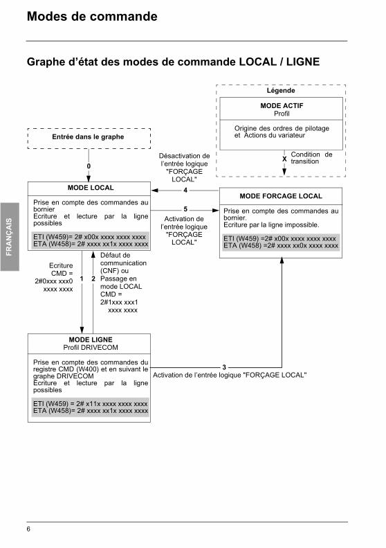
Graphe d’état des modes de commande LOCAL / LIGNE
MODE LIGNEProfil DRIVECOM
Prise en compte des commandes duregistre CMD (W400) et en suivant legraphe DRIVECOMEcriture et lecture par la lignepossibles
ETI (W459) = 2# x11x xxxx xxxx xxxxETA (W458)= 2# xxxx xx1x xxxx xxxx
MODE LOCAL
Prise en compte des commandes aubornierEcriture et lecture par la lignepossibles
ETI (W459)= 2# x00x xxxx xxxx xxxxETA (W458)= 2# xxxx xx1x xxxx xxxx
MODE FORCAGE LOCAL
Prise en compte des commandes aubornier. Ecriture par la ligne impossible.
ETI (W459) =2# x00x xxxx xxxx xxxxETA (W458) =2# xxxx xx0x xxxx xxxx
Entrée dans le graphe
Légende
MODE ACTIFProfil
Origine des ordres de pilotageet Actions du variateur
Défaut de communication (CNF) ou Passage en mode LOCALCMD = 2#1xxx xxx1 xxxx xxxx
Désactivation de l’entrée logique
"FORÇAGE LOCAL"
Activation de l’entrée logique
"FORÇAGE LOCAL"
EcritureCMD =
2#0xxx xxx0xxxx xxxx
Activation de l’entrée logique "FORÇAGE LOCAL"
Condition detransition
2
3
1
0X
4
5
6

FRA
NÇ
AIS
ATV38_58.book Page 7 Mardi, 11. février 2003 11:15 11
Modes de commande
Arrêts prioritairesLorsqu’on est en mode ligne les demandes d’arrêt qui peuvent être activées par le bornier ou par le terminalsont toujours prioritaires :
(1) Sauf si le paramètre PST est à "NON"
Contrôle du bus de communicationLe bit 14 (NTO) du mot de commande CMI permet de supprimer le contrôle de la communication.Si NTO = 1, le variateur ne prend plus en compte les erreurs de communication provenant du busde communication qui commande le variateur.Pour des raisons de sécurité son utilisation doit être réservée à la phase de mise au point ou àdes applications spéciales.
Adresses autoriséesSeules les adresses et valeurs définies dans ce document sont utilisables. Toute autreadresse ou valeur doit être considérée comme réservée et ne doit jamais faire l’objetd’écriture. Le non respect de cette précaution risque d’entraîner des dysfonctionnements.
Type d’arrêt Origine Etat Drivecom atteint Actions pour reprendre le contrôle de l’Altivar par le bus de terrain
Arrêt rapide LI2 à LI4 "Operation enabled" - positionner à 1 l’entrée logique affectée à la fonction "arrêt rapide" (active à 0)
Arrêt par injection de courant continu
LI2 à LI4 "Operation enabled" - positionner à 0 l’entrée logique affectée à la fonction "arrêt par injection" (active à 1)
Arrêt roue libre LI2 à LI4 "Switch on disabled" - positionner à 1 l’entrée logique affectée à la fonction "arrêt roue libre" (active à 0) - effectuer les transitions nécessaires pour retourner dans l’état variateur en marche.
En commande 3 fils arrêt par l’entrée logique STOP (LI1)
LI1 (commande 3 fils)
"Switch on disabled" - positionner à 1 l’entrée logique affectée à STOP (active à 0)- effectuer les transitions nécessaires pour retourner dans l’état variateur en marche.
Arrêt par le terminal Touche STOP(1)
"Switch on disabled" - relâcher la touche Stop- effectuer les transitions nécessaires pour retourner dans l’état variateur en marche.
7

FRA
NÇ
AIS
ATV38_58.book Page 8 Mardi, 11. février 2003 11:15 11
Contrôle et pilotage en mode LIGNE
Graphe d’état DRIVECOM
��� ����� �� ��� ����� ���� ����
��� �������
������ ����� ���� � ������
������ �������
� ���� � ����
�� �������
��� �������
�����!
��� �������
����"#
$�#��%
��� �������
��
&��'( ����
��� ������)
����"# $�#��%
��� �������
��
������'����
�*� �����+��
� '���%������
,����� � #*���-�.
��
���'� �/0
�� �����#
��
�/0 �� "����
������
���� ��������� ������������ $������� ���#�1�� � ���
��� �������
2����'��% �����# ���2
�������
� ��������
��� �������
������� �� ��� �� ����
�����������
�������� ������
��� �������
�������������� ������
��� �������
��� �� ����� ��-�
��� �����)3
24�52
!"#
$
!
��� �� ���%������ $�����##�
��� �����6�
27 �2
����� �� ��� ����� ����
��� �����)�
27 �2
&���' ��� ���������-� �*��%'
��� ������8
24�59 ���9 ��:2
( )
!*
!+
��"#
�������
��� ������;
��"#
�������
��� ������; ����"#
�������
��� ������8
��������� ���%������ ���'�
��� �����)8
24<79 4�59 ===2
����#� >
��� �����)8 > ���-� ����# ��
? ���'� �� �$��9 $���� �����
��� �����)8 > ���'� �� ����+�9 $���� �����
��� ����))8 > ���'� �� �$�� ��� �� ���
��� ����))8 > ���'� �� ����+� ��� �� ���
��� ������; > ���'� �� �$��
��� ������; > ���'� �� ����-�
��� ������; > ���-� ��� ����
��� ���)��; > ���-� �@'��� '����� '����
��� ���6��; > ���-� �����
* +
!!
!(
!��'� �
��� ������8 �����!
��� �������
�����!
��� �������
&��'( ����
��� ������:
"
",
-
.
/
����"#
$�#��%
��� �������
��
������'����
�*� �����+��
� '���%������
,����� � #*���-�.
!#
���� ����� � 2/������ �"#�2 ���� ��� 2&��'( ����2 ���-� ��� #�"�
����"# $�#��%
��� �������
��
������'����
�*� �����+��
� '���%������
,����� � #*���-�.
��
���'� �/0
�� �����#
��
�/0 �� "����
8

FRA
NÇ
AIS
ATV38_58.book Page 9 Mardi, 11. février 2003 11:15 11
Contrôle et pilotage en mode LIGNE
Le processus de commande de l’Altivar par liaison série est conforme au graphe d’état du standard DRIVECOM. Chaque état représente un comportement interne du variateur.
Ce graphe évolue en fonction de l'envoi du registre de commande (CMDD W601 ou CMD W400) ou parl’apparition d’un événement (exemple : verrouillage en défaut). L’identification de l’état du variateur estdonnée par la valeur du registre d’état (ETAD W602 ou ETA W458).
Not ready to switch on (Initialisation) :L'initialisation de la carte de communication se déroule.Cet état n'est visible qu'avec la carte Interbus - S (VW3-A58304E), qui peut être alimentée séparément.Avec les autres cartes c'est un état transitoire, pendant l'initialisation.
Switch on disabled (Configuration) :L'initialisation du variateur est terminée.Les paramètres de configuration et de réglage peuvent être modifiés.Si on désire charger tout ou partie de la configuration et des réglages, il est conseillé de désactiver lafonction contrôle de cohérence pendant le transfert (CMI W402, bit 15 = 1). A l'issue du transfert, on doitvalider le contrôle de cohérence (CMI W402, bit 15 = 0).Le variateur est verrouillé.
Ready to switch on et Switched on (Variateur initialisé) :Le variateur est verrouillé.L'étage puissance du variateur est prêt à fonctionner, mais la tension n'est pas appliquée en sortie.Les paramètres de configuration et de réglage peuvent être modifiés. La modification d'un paramètre deconfiguration provoque le retour à l'état Switch on disabled.
Operation enabled (Opérationnel) :Les fonctions d'entraînement du variateur sont activées, la tension est appliquée aux bornes du moteur.Seuls les paramètres de réglage peuvent être modifiés. La modification d'un paramètre de configuration(moteur à l'arrêt) provoque le retour à l'état Switch on disabled.L'autoréglage (TUN) nécessite une injection de courant, on doit donc être dans cet état pour cettecommande.
Quick stop active (Arrêt d'urgence actif) :Arrêt rapide.Le redémarrage n'est possible qu'après passage dans l'état Switch on disabled.
Malfunction reaction active (Réaction sur défaut) :Etat transitoire où le variateur exécute une action appropriée au type de défaut.La fonction d'entraînement est désactivée.
Malfunction (Défaut) :Variateur en défaut.Le variateur est verrouillé.
Particularité de DeviceNet :Le graphe d’état DriveCom ne s’applique pas à DeviceNet. Dans le cas de DeviceNet, le graphe d’état estpiloté par la carte de communication qui amène automatiquement le variateur dans l’état Operationenabled. Le programme de l’automate doit uniquement mettre à 1 la commande Run dans le registre decommande sans se préoccuper de la séquence de démarrage de DriveCom.
9
FRA
NÇ
AIS
ATV38_58.book Page 10 Mardi, 11. février 2003 11:15 11
Contrôle et pilotage en mode LIGNE
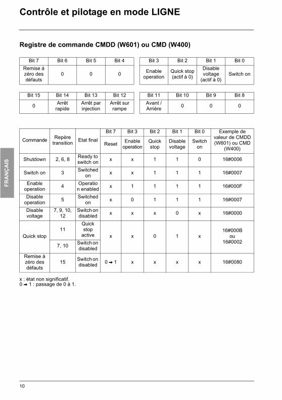
Registre de commande CMDD (W601) ou CMD (W400)
x : état non significatif.0 V 1 : passage de 0 à 1.
Bit 7 Bit 6 Bit 5 Bit 4 Bit 3 Bit 2 Bit 1 Bit 0Remise à zéro des défauts
0 0 0 Enable operation
Quick stop(actif à 0)
Disable voltage
(actif à 0)Switch on
Bit 15 Bit 14 Bit 13 Bit 12 Bit 11 Bit 10 Bit 9 Bit 8
0 Arrêt rapide
Arrêt par injection
Arrêt sur rampe
Avant / Arrière 0 0 0
Commande Repère transition Etat final
Bit 7 Bit 3 Bit 2 Bit 1 Bit 0 Exemple de valeur de CMDD (W601) ou CMD
(W400)Reset Enable
operationQuick stop
Disable voltage
Switch on
Shutdown 2, 6, 8 Ready to switch on x x 1 1 0 16#0006
Switch on 3 Switched on x x 1 1 1 16#0007
Enable operation 4 Operatio
n enabled x 1 1 1 1 16#000F
Disable operation 5 Switched
on x 0 1 1 1 16#0007
Disable voltage
7, 9, 10, 12
Switch on disabled x x x 0 x 16#0000
Quick stop11
Quick stop
active x x 0 1 x16#000B
ou16#0002
7, 10 Switch on disabled
Remise à zéro des défauts
15 Switch on disabled 0 V 1 x x x x 16#0080
10

FRA
NÇ
AIS
ATV38_58.book Page 11 Mardi, 11. février 2003 11:15 11
Contrôle et pilotage en mode LIGNE
Registre d'état ETAD (W602) ou ETA (W458)
x : état non significatif.
(1) Le bit 4 du registre d’état ETA correspond à "Voltage distabled".
Bit 7 Bit 6 Bit 5 Bit 4 Bit 3 Bit 2 Bit 1 Bit 0
Alarme Switch on disabled
Quick stopactif à 0
0(1) Malfunction Operation
enabledSwitched
onReady to switch on
Bit 15 Bit 14 Bit 13 Bit 12 Bit 11 Bit 10 Bit 9 Bit 8
Sens de rotation
Arrêt touche STOP
0 0 Consigne hors limites
Consigne atteinte
Forçage local
(actif à 0)0
EtatBit 6 Bit 5 Bit 3 Bit 2 Bit 1 Bit 0 ETA (W458)
masqué par16#006F
Switch on disabled Quick stop Malfunc-
tionOperation enabled
Switched on
Ready to switch on
Not ready to switch on 0 x 0 0 0 0 16#0000
16#0020Switch on disabled 1 x 0 0 0 0 16#0040
16#0060Ready to switch on 0 1 0 0 0 1 16#0021
Switched on 0 1 0 0 1 1 16#0023Operation enabled 0 1 0 1 1 1 16#0027
Malfunction 0 x 1 0 0 0 16#000816#0028
Malfunction reaction active 0 x 1 1 1 1 16#000F
16#002FQuick stop active 0 0 0 1 1 1 16#0007
11
FRA
NÇ
AIS
ATV38_58.book Page 12 Mardi, 11. février 2003 11:15 11
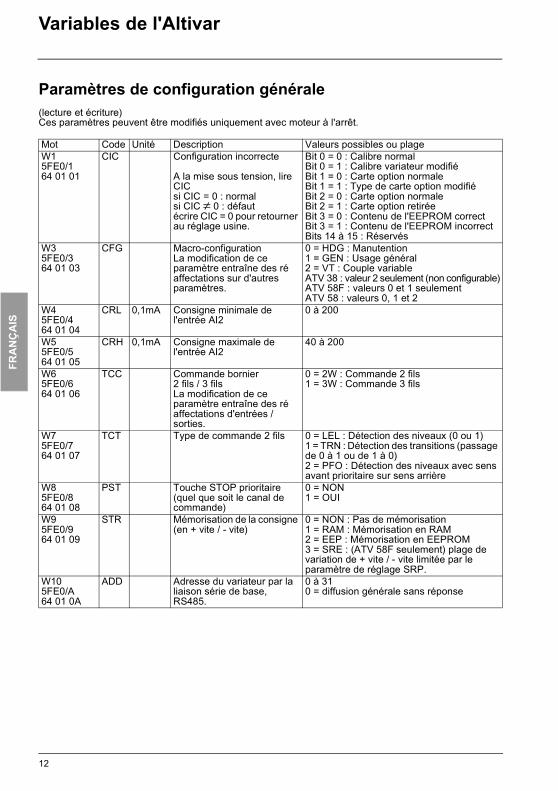
Variables de l'Altivar
Paramètres de configuration générale(lecture et écriture)Ces paramètres peuvent être modifiés uniquement avec moteur à l'arrêt.
Mot Code Unité Description Valeurs possibles ou plageW15FE0/164 01 01
CIC Configuration incorrecte
A la mise sous tension, lire CICsi CIC = 0 : normalsi CIC ≠ 0 : défaut écrire CIC = 0 pour retourner au réglage usine.
Bit 0 = 0 : Calibre normalBit 0 = 1 : Calibre variateur modifiéBit 1 = 0 : Carte option normaleBit 1 = 1 : Type de carte option modifiéBit 2 = 0 : Carte option normaleBit 2 = 1 : Carte option retiréeBit 3 = 0 : Contenu de l'EEPROM correctBit 3 = 1 : Contenu de l'EEPROM incorrectBits 14 à 15 : Réservés
W35FE0/364 01 03
CFG Macro-configurationLa modification de ce paramètre entraîne des ré affectations sur d'autres paramètres.
0 = HDG : Manutention1 = GEN : Usage général2 = VT : Couple variableATV 38 : valeur 2 seulement (non configurable)ATV 58F : valeurs 0 et 1 seulementATV 58 : valeurs 0, 1 et 2
W45FE0/464 01 04
CRL 0,1mA Consigne minimale de l'entrée AI2
0 à 200
W55FE0/564 01 05
CRH 0,1mA Consigne maximale de l'entrée AI2
40 à 200
W65FE0/664 01 06
TCC Commande bornier 2 fils / 3 filsLa modification de ce paramètre entraîne des ré affectations d'entrées / sorties.
0 = 2W : Commande 2 fils1 = 3W : Commande 3 fils
W75FE0/764 01 07
TCT Type de commande 2 fils 0 = LEL : Détection des niveaux (0 ou 1)1 = TRN : Détection des transitions (passage de 0 à 1 ou de 1 à 0)2 = PFO : Détection des niveaux avec sens avant prioritaire sur sens arrière
W85FE0/864 01 08
PST Touche STOP prioritaire (quel que soit le canal de commande)
0 = NON1 = OUI
W95FE0/964 01 09
STR Mémorisation de la consigne (en + vite / - vite)
0 = NON : Pas de mémorisation1 = RAM : Mémorisation en RAM2 = EEP : Mémorisation en EEPROM3 = SRE : (ATV 58F seulement) plage de variation de + vite / - vite limitée par le paramètre de réglage SRP.
W105FE0/A64 01 0A
ADD Adresse du variateur par la liaison série de base, RS485.
0 à 310 = diffusion générale sans réponse
12

FRA
NÇ
AIS
ATV38_58.book Page 13 Mardi, 11. février 2003 11:15 11
Variables de l'Altivar
Paramètres de configuration générale(lecture et écriture)Ces paramètres peuvent être modifiés uniquement avec moteur à l'arrêt.
Mot Code Unité Description Valeurs possibles ou plageW115FE0/B64 01 0B
ORT Application à couple standard.Ce paramètre ne peut être modifié que sur les calibres ATV 58 supérieurs à 7,5 kW en 208/240V et 15 kW en 380/500V. La modification de ce paramètre entraîne un retour au réglage usine des paramètres : UNS, NCR, NSP, COS, TUN, ITH, IDC.Pour tous les ATV 38, ATV 58F et les autres calibres ATV 58, il est toujours à 0.
0 = NON (fort couple)1 = OUI (couple standard)
W125FE0/C64 01 0C
RIN Inhibition de la marche en sens inverse de celui demandé par les entrées logiques, même si cette inversion est requise par une fonction sommation ou régulation.Inhibition du sens arrière s'il est demandé par la touche REV du terminal.
0 = NON1 = OUI
W135FE0/D64 01 0D
BSP Ecrêtage / Epiétage de la consigne. 0 = NON : normal1 = BLS : écrêtage2 = BNS : épiétage
W145FE0/E64 01 0E
AOL 0,1mA Valeur minimale de la sortie AO, et de la sortie AO1.
0 à 200
W155FE0/F64 01 0F
AOH 0,1mA Valeur maximale de la sortie AO, et de la sortie AO1.
0 à 200
W165FE0/1064 01 10
TBR Vitesse de transmission par la liaison série RS485
7 = 9600 Bits / seconde8 = 19200 Bits / seconde
W175FE0/1164 01 11
RPR Remise à zéro des kWh ou du temps de fonctionnement.La remise à zéro est immédiate, puis le paramètre repasse automatique-ment à 0. Il est donc toujours lu à 0.
0 = NON1 = Remise à zéro des kWh2 = Remise à zéro du temps de fonctionnement
13

FRA
NÇ
AIS
ATV38_58.book Page 14 Mardi, 11. février 2003 11:15 11
Variables de l'Altivar
Paramètres de configuration de l'entraînement(lecture et écriture)Ces paramètres peuvent être modifiés uniquement avec moteur à l'arrêt.
Mot Code Unité Description Valeurs possibles ou plageW505FE1/165 01 01
SFT Type de découpage.Un passage de LF à HF1 ou HF2 ou vice versa entraîne un réglage usine des paramètres SFR et NRD. Un passage de LF ou HF1 à HF2 ou vice versa entraîne un réglage usine des paramètres NCR, CLI, ITH, IDC, IBR et CTD.
0 = LF : Basse fréquence1 = HF1 : Haute fréquence sans déclassement (Si th >= 95% :- passage à 2 ou 4 kHz selon le calibre.Si th < 70% : - retour à la fréquence "SFR")2 = HF2 : Haute fréquence avec déclassement d'un calibre
W515FE1/265 01 02
SFR Fréquence de découpageLes fréquences 8 kHz, 12 kHz et 16 kHz ne sont accessibles que sur certains calibres de variateurs (voir guide de programmation).
0 = Découpage à 0,5kHz si SFT = LF1 = Découpage à 1kHz si SFT = LF2 = Découpage à 2kHz si SFT = LF3 = Découpage à 4kHz si SFT = LF ou HF1/HF2 selon calibre variateur4 = Découpage à 8kHz si SFT = HF1 ou HF25 = Découpage à 12kHz si SFT = HF1 ou HF26 = Découpage à 16kHz si SFT = HF1 ou HF2
W525FE1/365 01 03
TFR 0,1Hz Fréquence maximale SFR = "0,5" : 100 à 620SFR = "1" : 100 à 1250SFR = "2" : 100 à 2500SFR = "4" ,"8", "12", "16" : 100 à 5000 pour ATV 38 et ATV 58 et 100 à 4500 pour ATV 58F
W535FE1/465 01 04
FRS 0,1Hz Fréquence nominale moteur 100 à 5000
W545FE1/565 01 05
NCR 0,1A Courant nominal moteur ATV 38 : 0,25 INV à 1,1 INVATV58 et ATV 58F : 0,25 INV à 1,36 INV(INV : courant nominal variateur)
W555FE1/665 01 06
UNS 1V Tension nominale moteur ATV 38 : 200 à 480ATV 58•••M2 : 200 à 240ATV 58•••N4 : 200 à 500ATV 58F•••N4 : 200 à 500
W565FE1/765 01 07
NSP 1rpm Vitesse nominale moteur 0 à 32767
W575FE1/865 01 08
COS 0,01 Cosinus Phi moteur 50 à 100
W585FE1/965 01 09
TLI 1% Limitation de couple(sauf ATV 38)
0 à 200
W595FE1/A65 01 0A
TUN Auto réglagePour demander un auto réglage il faut être dans l’état "Opération enabled".
0 = NON : Auto réglage non effectué(on utilise une valeur tabulée).Si écriture : retour à cette valeur tabulée1 = OUI : Commande d'auto réglage2 = Fait : Auto réglage effectué
W605FE1/B65 01 0B
NRD Réduction du bruit moteur 0 = NON1 = OUI
14
FRA
NÇ
AIS
ATV38_58.book Page 15 Mardi, 11. février 2003 11:15 11
Variables de l'Altivar
Paramètres de configuration de l'entraînement(lecture et écriture)Ces paramètres peuvent être modifiés uniquement avec moteur à l'arrêt.
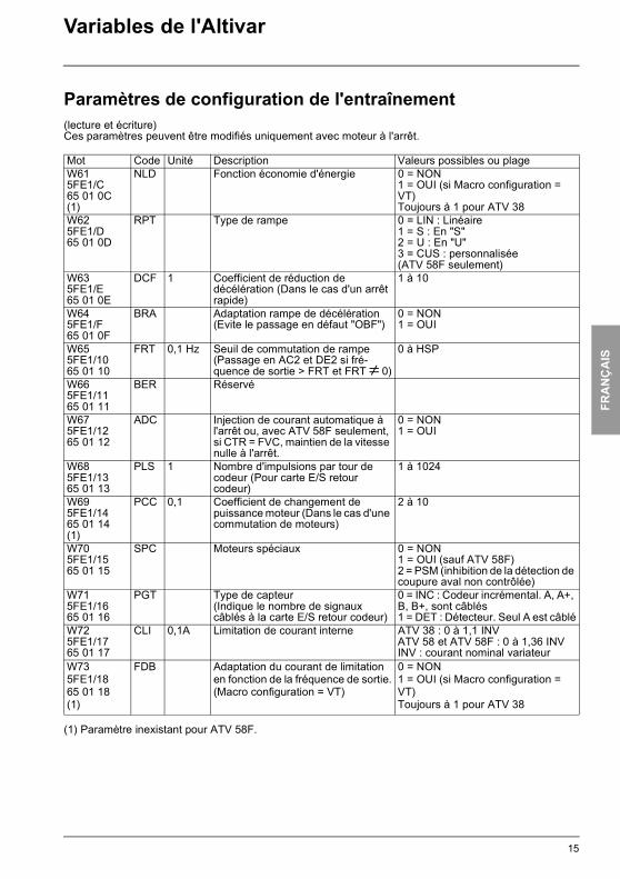
(1) Paramètre inexistant pour ATV 58F.
Mot Code Unité Description Valeurs possibles ou plageW615FE1/C65 01 0C(1)
NLD Fonction économie d'énergie 0 = NON1 = OUI (si Macro configuration = VT)Toujours à 1 pour ATV 38
W625FE1/D65 01 0D
RPT Type de rampe 0 = LIN : Linéaire1 = S : En "S"2 = U : En "U"3 = CUS : personnalisée (ATV 58F seulement)
W635FE1/E65 01 0E
DCF 1 Coefficient de réduction de décélération (Dans le cas d'un arrêt rapide)
1 à 10
W645FE1/F65 01 0F
BRA Adaptation rampe de décélération(Evite le passage en défaut "OBF")
0 = NON1 = OUI
W655FE1/1065 01 10
FRT 0,1 Hz Seuil de commutation de rampe(Passage en AC2 et DE2 si fré-quence de sortie > FRT et FRT ≠ 0)
0 à HSP
W665FE1/1165 01 11
BER Réservé
W675FE1/1265 01 12
ADC Injection de courant automatique à l'arrêt ou, avec ATV 58F seulement, si CTR = FVC, maintien de la vitesse nulle à l'arrêt.
0 = NON1 = OUI
W685FE1/1365 01 13
PLS 1 Nombre d'impulsions par tour de codeur (Pour carte E/S retour codeur)
1 à 1024
W695FE1/1465 01 14(1)
PCC 0,1 Coefficient de changement de puissance moteur (Dans le cas d'une commutation de moteurs)
2 à 10
W705FE1/1565 01 15
SPC Moteurs spéciaux 0 = NON1 = OUI (sauf ATV 58F)2 = PSM (inhibition de la détection de coupure aval non contrôlée)
W715FE1/1665 01 16
PGT Type de capteur(Indique le nombre de signaux câblés à la carte E/S retour codeur)
0 = INC : Codeur incrémental. A, A+, B, B+, sont câblés1 = DET : Détecteur. Seul A est câblé
W725FE1/1765 01 17
CLI 0,1A Limitation de courant interne ATV 38 : 0 à 1,1 INVATV 58 et ATV 58F : 0 à 1,36 INVINV : courant nominal variateur
W735FE1/1865 01 18(1)
FDB Adaptation du courant de limitation en fonction de la fréquence de sortie.(Macro configuration = VT)
0 = NON1 = OUI (si Macro configuration = VT)Toujours à 1 pour ATV 38
15

FRA
NÇ
AIS
ATV38_58.book Page 16 Mardi, 11. février 2003 11:15 11
Variables de l'Altivar
Paramètres de configuration de l'entraînement(lecture et écriture)Ces paramètres peuvent être modifiés uniquement avec moteur à l'arrêt, à l'exception de W74 (FLU) quipeut être modifié en marche. Ce paramètre FLU est accessible par le terminal d'exploitation et par l'atelierlogiciel dans le menu REGLAGES.
Les mots W74 à W78 n'existent que sur les ATV 58F.
Mot Code Unité Description Valeurs possibles ou plageW745FE1/1965 01 19
FLU Fluxage moteur. 0 = FNC : Fluxage non continu1 = FCT : Fluxage continu
W755FE1/1A65 01 1A
CTR Choix du mode de contrôle 0 = SVC : Boucle ouverte1 = FVC : Boucle fermée
W765FE1/1B65 01 1B
PGI 1 Nombre de points par tour du codeur (carte contrôle)
100 à 5000
W775FE1/1C65 01 1C
SSL Choix du type de boucle vitesse 0 = IP : Structure IP1 = PI : Structure PI
W785FE1/1D65 01 1D
ENC Vérification du retour codeur.Les valeurs 0 et 2 ne sont pas à écrire.La valeur 1 ne doit plus être écrite si W78 = 2.
0 = NON : Test non effectué1 = OUI : Commande de test2 = FAIT : Test effectué
W795FE1/1E65 01 1E
STT Type d’arrêt.Sur demande d’arrêt, le type d’arrêt choisi est actif jusqu’au seuil FFT. En dessous de ce seuil l’arrêt s’effectue en roue libre.
0 = STN : Sur rampe1 = FST : Arrêt rapide2 = NST : Arrêt roue libre3 = DCI : Arrêt par injection de courant continu
16

FRA
NÇ
AIS
ATV38_58.book Page 17 Mardi, 11. février 2003 11:15 11
Variables de l'Altivar
Paramètres de configuration des entrées / sorties(lecture et écriture)Ces paramètres peuvent être modifiés uniquement avec moteur à l'arrêt.
Mot Code Description Valeurs possibles ou plageW1005FE2/166 01 01
LI1 Affectation de l'entrée logique "LI1"
1 = STP : Stop. (Si TCC = 3W)2 = FW : Marche avant. (Si TCC = 2 W)
W1015FE2/266 01 02
LI2 Affectation de l'entrée logique "LI2"
0 = NON : Non affectée2 = FW : Marche avant. (Si TCC = 3W)3 = RV : Marche arrière4 = RP2 : Commutation de rampe5 = JOG : Marche pas à pas6 = + SP : + Vite7 = - SP : - Vite8 = PS2 : 2 Vitesses présélectionnées11 = RFC : Commutation de référence12 = NST : Arrêt roue libre13 = DCI : Arrêt par injection14 = FST : Arrêt rapide15 = CHP : Commutation de moteurs ou, avec ATV 58F seulement, si CTR = FVC, commutation boucle ouverte / boucle fermée.16 = TL2 : Seconde limitation de couple (sauf ATV 38)17 = FLO : Forçage local18 = RST : Effacement des défauts19 = ATN : Autoréglage22 = PAU : Auto-manu PI(D)24 = PR2 : 2 consignes PI(D) présélectionnées26 = TLA : Limitation de couple par AI (sauf ATV 38)27 = EDD : Défaut externeValeurs spécifiques à l'ATV 58F :20 = SPM : Mémorisation de consigne21 = FLI : Fluxage moteur23 = PIS : Shuntage intégrale PI(D)Valeur spécifique à l'ATV 38 :28 = FTK : Forçage console (mode terminal)
17

FRA
NÇ
AIS
ATV38_58.book Page 18 Mardi, 11. février 2003 11:15 11
Variables de l'Altivar
Paramètres de configuration des entrées / sorties(lecture et écriture)Ces paramètres peuvent être modifiés uniquement avec moteur à l'arrêt.
Mot Code Description Valeurs possibles ou plageW1025FE2/366 01 03
LI3 Affectation de l'entrée logique "LI3"
0 = NON : Non affectée3 = RV : Marche arrière4 = RP2 : Commutation de rampe5 = JOG : Marche pas à pas6 = +SP : + Vite7 = -SP : - Vite8 = PS2 : 2 Vitesses présélectionnées9 = PS4 : 4 Vitesses présélectionnées11 = RFC : Commutation de référence12 = NST : Arrêt roue libre13 = DCI : Arrêt par injection14 = FST : Arrêt rapide15 = CHP : Commutation de moteurs ou, avec ATV 58F seulement, si CTR = FVC, commutation boucle ouverte / boucle fermée.16 = TL2 : Seconde limitation de couple (sauf ATV 38)17 = FLO : Forçage local18 = RST : Effacement des défauts19 = ATN : Autoréglage22 = PAU : Auto-manu PI(D)24 = PR2 : 2 consignes PI(D) présélectionnées25 = PR4 : 4 consignes PI(D) présélectionnées26 = TLA : Limitation de couple par AI (sauf ATV 38)27 = EDD : Défaut externeValeurs spécifiques à l'ATV 58F :20 = SPM : Mémorisation de consigne21 = FLI : Fluxage moteur23 = PIS : Shuntage intégrale PI(D)Valeur spécifique à l'ATV 38 :28 = FTK : Forçage console (mode terminal)
W1035FE2/466 01 04
LI4 Affectation de l'entrée logique "LI4"
Identique à W102
W1045FE2/566 01 05
LI5 Affectation de l'entrée logique "LI5"
Identique à W102
W1055FE2/666 01 06
LI6 Affectation de l'entrée logique "LI6"
Identique à W102
18

FRA
NÇ
AIS
ATV38_58.book Page 19 Mardi, 11. février 2003 11:15 11
Variables de l'Altivar
Paramètres de configuration des entrées / sorties(lecture et écriture)Ces paramètres peuvent être modifiés uniquement avec moteur à l'arrêt.
Nota : Les affectations relatives au régulateur PI(D) ne sont accessibles que si une entrée analogique estaffectée à PIF : retour PI(D)
Mot Code Description Valeurs possibles ou plageW1075FE2/866 01 08
AI2 Affectation de l'entrée analogique "AI2"
0 = NON : Non affectée2 = FR2 : Référence vitesse N°23 = SAI : Référence sommatrice4 = PIF : Retour PI (Régulateur PI)Valeurs spécifiques à l'ATV 58F :8 = ATL : Limitation de couple9 = DAI : référence soustractrice
W1085FE2/966 01 09
AI3 Affectation de l'entrée analogique "AI3" ou de l'entrée codeur (selon type de carte E / S)
0 = NON : Non affectée2 = FR2 : Référence vitesse n°2 (spécifique ATV 38)3 = SAI : Référence sommatrice4 = PIF : Retour PI (Régulateur PI)5 = SFB : Retour dynamo tachymétrique6 = RGI : Retour codeur (sauf ATV 58F)7 = PTC : Sondes PTC8 = ATL : Limitation de couple (sauf ATV 38)10 = PIM : Consigne de vitesse manuelle du régulateur PI(D) (auto-manu)Valeurs spécifiques à l'ATV 58F :9 = DAI : Référence soustractrice11 = FPI : Consigne vitesse du régulateur PI(D) (consigne prédictive)
19
FRA
NÇ
AIS
ATV38_58.book Page 20 Mardi, 11. février 2003 11:15 11
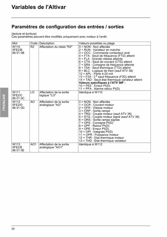
Variables de l'Altivar
Paramètres de configuration des entrées / sorties(lecture et écriture)Ces paramètres peuvent être modifiés uniquement avec moteur à l'arrêt.
Mot Code Description Valeurs possibles ou plageW1105FE2/B66 01 0B
R2 Affectation du relais "R2" 0 = NON : Non affectée2 = RUN : Variateur en marche3 = OCC : Commande contacteur aval4 = FTA : Seuil de fréquence (FTD) atteint5 = FLA : Grande vitesse atteinte6 = CTA : Seuil de courant (CTD) atteint7 = SRA : Consigne de fréquence atteinte8 = TSA : Seuil thermique (TTD) atteint9 = BLC : Logique de frein (sauf ATV 38)12 = APL : Perte 4-20 mA13 = F2A : 2 e seuil fréquence (F2D) atteint14 = TAD : Seuil état thermique variateur atteintValeurs spécifiques à l'ATV 58F :10 = PEE : Erreur PI(D)11 = PFA : Alarme retour PI(D)
W1115FE2/C66 01 0C
LO Affectation de la sortie logique "LO"
Identique à W110
W1125FE2/D66 01 0D
AO Affectation de la sortie analogique "AO"
0 = NON : Non affectée 1 = OCR : Courant moteur 2 = OFR : Vitesse moteur3 = ORP : Sortie rampe 4 = TRQ : Couple moteur (sauf ATV 38)5 = STQ : Couple moteur signé (sauf ATV 38)6 = ORS : Sortie rampe signée7 = OPS : Consigne PI(D)8 = OPF : Retour PI(D)9 = OPE : Erreur PI(D)10 = OPI : Intégrale PI(D)11 = OPR : Puissance moteur12 = THR : Etat thermique moteur13 = THD : Etat thermique variateur
W1135FE2/E66 01 0E
AO1 Affectation de la sortie analogique "AO1"
Identique à W112
20
FRA
NÇ
AIS
ATV38_58.book Page 21 Mardi, 11. février 2003 11:15 11
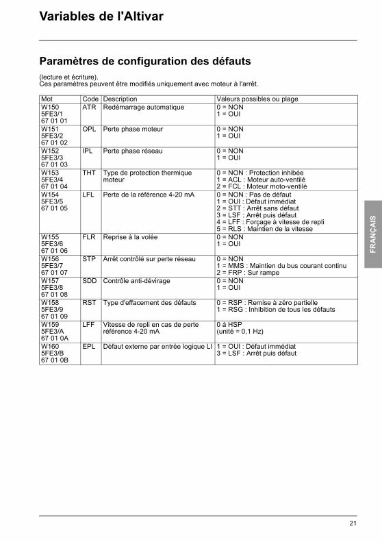
Variables de l'Altivar
Paramètres de configuration des défauts(lecture et écriture).Ces paramètres peuvent être modifiés uniquement avec moteur à l'arrêt.
Mot Code Description Valeurs possibles ou plageW1505FE3/167 01 01
ATR Redémarrage automatique 0 = NON1 = OUI
W1515FE3/267 01 02
OPL Perte phase moteur 0 = NON1 = OUI
W1525FE3/367 01 03
IPL Perte phase réseau 0 = NON1 = OUI
W1535FE3/467 01 04
THT Type de protection thermique moteur
0 = NON : Protection inhibée1 = ACL : Moteur auto-ventilé2 = FCL : Moteur moto-ventilé
W1545FE3/567 01 05
LFL Perte de la référence 4-20 mA 0 = NON : Pas de défaut1 = OUI : Défaut immédiat2 = STT : Arrêt sans défaut3 = LSF : Arrêt puis défaut4 = LFF : Forçage à vitesse de repli5 = RLS : Maintien de la vitesse
W1555FE3/667 01 06
FLR Reprise à la volée 0 = NON1 = OUI
W1565FE3/767 01 07
STP Arrêt contrôlé sur perte réseau 0 = NON1 = MMS : Maintien du bus courant continu2 = FRP : Sur rampe
W1575FE3/867 01 08
SDD Contrôle anti-dévirage 0 = NON1 = OUI
W1585FE3/967 01 09
RST Type d'effacement des défauts 0 = RSP : Remise à zéro partielle1 = RSG : Inhibition de tous les défauts
W1595FE3/A67 01 0A
LFF Vitesse de repli en cas de perte référence 4-20 mA
0 à HSP(unité = 0,1 Hz)
W1605FE3/B67 01 0B
EPL Défaut externe par entrée logique LI 1 = OUI : Défaut immédiat3 = LSF : Arrêt puis défaut
21
FRA
NÇ
AIS
ATV38_58.book Page 22 Mardi, 11. février 2003 11:15 11
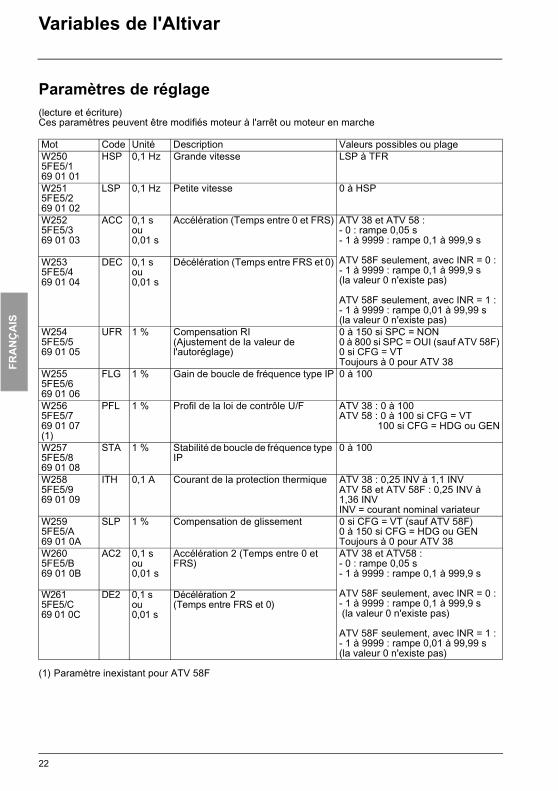
Variables de l'Altivar
Paramètres de réglage(lecture et écriture)Ces paramètres peuvent être modifiés moteur à l'arrêt ou moteur en marche
(1) Paramètre inexistant pour ATV 58F
Mot Code Unité Description Valeurs possibles ou plageW2505FE5/169 01 01
HSP 0,1 Hz Grande vitesse LSP à TFR
W2515FE5/269 01 02
LSP 0,1 Hz Petite vitesse 0 à HSP
W2525FE5/369 01 03
ACC 0,1 sou0,01 s
Accélération (Temps entre 0 et FRS) ATV 38 et ATV 58 :- 0 : rampe 0,05 s- 1 à 9999 : rampe 0,1 à 999,9 s
ATV 58F seulement, avec INR = 0 :- 1 à 9999 : rampe 0,1 à 999,9 s(la valeur 0 n'existe pas)
ATV 58F seulement, avec INR = 1 :- 1 à 9999 : rampe 0,01 à 99,99 s(la valeur 0 n'existe pas)
W2535FE5/469 01 04
DEC 0,1 sou0,01 s
Décélération (Temps entre FRS et 0)
W2545FE5/569 01 05
UFR 1 % Compensation RI(Ajustement de la valeur de l'autoréglage)
0 à 150 si SPC = NON0 à 800 si SPC = OUI (sauf ATV 58F)0 si CFG = VTToujours à 0 pour ATV 38
W2555FE5/669 01 06
FLG 1 % Gain de boucle de fréquence type IP 0 à 100
W2565FE5/769 01 07(1)
PFL 1 % Profil de la loi de contrôle U/F ATV 38 : 0 à 100ATV 58 : 0 à 100 si CFG = VT 100 si CFG = HDG ou GEN
W2575FE5/869 01 08
STA 1 % Stabilité de boucle de fréquence type IP
0 à 100
W2585FE5/969 01 09
ITH 0,1 A Courant de la protection thermique ATV 38 : 0,25 INV à 1,1 INVATV 58 et ATV 58F : 0,25 INV à 1,36 INVINV = courant nominal variateur
W2595FE5/A69 01 0A
SLP 1 % Compensation de glissement 0 si CFG = VT (sauf ATV 58F)0 à 150 si CFG = HDG ou GENToujours à 0 pour ATV 38
W2605FE5/B69 01 0B
AC2 0,1 sou0,01 s
Accélération 2 (Temps entre 0 et FRS)
ATV 38 et ATV58 :- 0 : rampe 0,05 s- 1 à 9999 : rampe 0,1 à 999,9 s
ATV 58F seulement, avec INR = 0 :- 1 à 9999 : rampe 0,1 à 999,9 s (la valeur 0 n'existe pas)
ATV 58F seulement, avec INR = 1 :- 1 à 9999 : rampe 0,01 à 99,99 s(la valeur 0 n'existe pas)
W2615FE5/C69 01 0C
DE2 0,1 sou0,01 s
Décélération 2(Temps entre FRS et 0)
22
FRA
NÇ
AIS
ATV38_58.book Page 23 Mardi, 11. février 2003 11:15 11
Variables de l'Altivar
Paramètres de réglage(lecture et écriture)Ces paramètres peuvent être modifiés moteur à l'arrêt ou moteur en marche
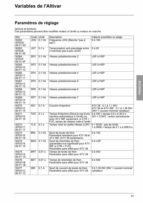
Mot Code Unité Description Valeurs possibles ou plageW2625FE5/D69 01 0D
JOG 0,1 Hz Fréquence JOG (Marche "pas à pas")
0 à 100
W2635FE5/E69 01 0E
JGT 0,1 s Temporisation anti-pianotage entre 2 marches pas à pas (JOG)
0 à 20
W2645FE5/F69 01 0F
SP2 0,1 Hz Vitesse présélectionnée 2 LSP à HSP
W2655FE5/1069 01 10
SP3 0,1 Hz Vitesse présélectionnée 3 LSP à HSP
W2665FE5/1169 01 11
SP4 0,1 Hz Vitesse présélectionnée 4 LSP à HSP
W2675FE5/1269 01 12
SP5 0,1 Hz Vitesse présélectionnée 5 LSP à HSP
W2685FE5/1369 01 13
SP6 0,1 Hz Vitesse présélectionnée 6 LSP à HSP
W2695FE5/1469 01 14
SP7 0,1 Hz Vitesse présélectionnée 7 LSP à HSP
W2705FE5/1569 01 15
IDC 0,1 A Courant d'injection ATV 38 : 0,1 à 1,1 INVATV 58 et ATV 58F : 0,1 à 1,36 INV(INV = courant nominal variateur)
W2715FE5/1669 01 16
TDC 0,1 s Temps d'injection (Dans le cas d'une injection automatique à l'arrêt) ou, avec ATV 58F seulement, si CTR = FVC, temps de vitesse nulle à l'arrêt
0 à 300 = temps 0,0 s à 30,0 s301 = CONT : action permanente
W2725FE5/1769 01 17
TLS 0,1 s Temps maxi en petite vitesse (LSP) 0 = NON : pas de limite 1 à 9999 = temps de 0,1 s à 999,9 s
W2735FE5/1869 01 18
BRL 0,1 Hz Seuil de levée de freinParamètre inexistant pour ATV 38 et ATV 58F (ATV 58 seulement).
0 à 100
W2745FE5/1969 01 19
BEN 0,1 Hz Seuil de retombée de frein(paramètre non significatif pour ATV 58F si CTR = FVC)Paramètre sans effet pour ATV 38
0 à LSP
W2755FE5/1A69 01 1A
BRT 0,01 s Temps de levée de freinParamètre sans effet pour ATV 38
0 à 500
W2765FE5/1B69 01 1B
BET 0,01 s Temps de retombée de freinParamètre sans effet pour ATV 38
0 à 500
W2775FE5/1C69 01 1C
IBR 0,1 A Seuil de courant de levée de freinParamètre sans effet pour ATV 38
0 à 1,36 INV (INV = courant nominal variateur)
23

FRA
NÇ
AIS
ATV38_58.book Page 24 Mardi, 11. février 2003 11:15 11
Variables de l'Altivar
Paramètres de réglage(lecture et écriture)Ces paramètres peuvent être modifiés moteur à l'arrêt ou moteur en marche
Les mots W294 à W307 et le mot W310 n'existent que pour les ATV 58F
Mot Code Unité Description Valeurs possibles ou plageW2785FE5/1D69 01 1D
TL2 1 % Seconde limitation de couple(sauf ATV 38)
0 à 200
W2795FE5/1E69 01 1E
RPG 0,01 Gain proportionnel du PI 1 à 10000
W2805FE5/1F69 01 1F
RIG 0,01/s Gain intégral du PI 1 à 10000
W2815FE5/2069 01 20
FBS 0,1 Facteur d'échelle du retour PIParamètre inexistant pour ATV 58F
10 à 1000
W2825FE5/2169 01 21
CTD 0,1 A Seuil de courant ATV 38 : 0 à 1,1 INVATV 58 et ATV 58F : 0 à 1,36 INVINV. = courant nominal variateur
W2835FE5/2269 01 22
TTD 1 % Seuil état thermique moteur 0 à 118
W2845FE5/2369 01 23
FTD 0,1 Hz Seuil de fréquence LSP à HSP
W2855FE5/2469 01 24
DTS 0,01 Facteur d'échelle du retour tachymétrique (Pour carte E/S avec entrée analogique)
100 à 200
W2865FE5/2569 01 25
JPF 0,1 Hz Fréquence occultée (plage de fréquence : +/- 2,5 Hz)
0 à HSP
W2875FE5/2669 01 26
PIC Inversion du sens de correction du régulateur PI
0 = NON1 = OUI
W2885FE5/2769 01 27
SDC 0,1 A Intensité du courant de freinage par injection à l'arrêt appliqué au bout de 30 secondes
ATV 38 : 0,1 à 1,1 INVATV 58 et ATV 58F : 0,1 à 1,36 INV(INV = courant nominal variateur)
W2895FE5/2869 01 28
USC 0,01 Coefficient appliqué à RFR pour l'affichage de la vitesse machine par USP (USP = RFR x USC)
1 à 10000
W2905FE5/2969 01 29
BIP Impulsion de levée de freinParamètre sans effet pour ATV 38
0 = NON : Impulsion dans le sens demandé1 = OUI : Impulsion toujours dans le sens "montée"
W2915FE5/2A69 01 2A
INR Incrément (finesse) des réglages de rampes
0 = 0,1 s1 = 0,01 s
W2925FE5/2B69 01 2B
SRP 1% Plage d'action de "plus vite" "moins vite" autour de la consigne
0 à 50% de la consigne
W2935FE5/2C69 01 2C
TA1 1% Arrondi du début de rampe d'accélération
0 à 100% du temps de rampe
24
FRA
NÇ
AIS
ATV38_58.book Page 25 Mardi, 11. février 2003 11:15 11
Variables de l'Altivar
Paramètres de réglage(lecture et écriture)Ces paramètres peuvent être modifiés moteur à l'arrêt ou moteur en marche
Les mots W294 à W307 et le mot W310 n'existent que pour les ATV 58F
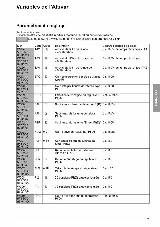
Mot Code Unité Description Valeurs possibles ou plageW2945FE5/2D69 01 2D
TA2 1 % Arrondi de la fin de rampe d'accélération
0 à 100% du temps de rampe -TA1
W2955FE5/2E69 01 2E
TA3 1% Arrondi du début de rampe de décélération
0 à 100% du temps de rampe
W2965FE5/2F69 01 2F
TA4 1% Arrondi de la fin de rampe de décélération
0 à 100% du temps de rampe -TA3
W2975FE5/3069 01 30
SPG 1% Gain proportionnel boucle de vitesse type PI
0 à 1000
W2985FE5/3169 01 31
SIG 1% Gain intégral boucle de vitesse type PI
0 à 1000
W2995FE5/3269 01 32
REO Offset de la consigne du régulateur PI(D)
-999 à +999
W3005FE5/3369 01 33
PAL 1% Seuil mini de l'alarme du retour PI(D) 0 à 100%
W3015FE5/3469 01 34
PAH 1% Seuil maxi de l'alarme du retour PI(D)
0 à 100%
W3025FE5/3569 01 35
PER 1% Seuil maxi de l'alarme "Erreur PI(D)" 0 à 100%
W3035FE5/3669 01 36
RDG 0,01 Gain dérivé du régulateur PI(D) 0 à 10000
W3045FE5/3769 01 37
PSP 0,1 s Constante de temps du filtre du retour PI(D)
0 à 100
W3055FE5/3869 01 38
PSR 1% Ratio du multiplicateur d'entrée vitesse du PI(D)
0 à 100
W3065FE5/3969 01 39
PLR 1% Ratio de l'écrêtage du régulateur PI(D)
0 à 100
W3075FE5/3A69 01 3A
PLB 0,1Hz Talon de l'écrêtage du régulateur PI(D)
0 à HSP
W3085FE5/3B69 01 3B
PI2 1% 2è consigne PI(D) présélectionnée 0 à 100
W3095FE5/3C69 01 3C
PI3 1% 3è consigne PI(D) présélectionnée 0 à 100
W3105FE5/3D69 01 3D
PRG Gain de la consigne du régulateur PI(D)
-999 à +999
25

FRA
NÇ
AIS
ATV38_58.book Page 26 Mardi, 11. février 2003 11:15 11
Variables de l'Altivar
Paramètres de réglage(lecture et écriture)Ces paramètres peuvent être modifiés moteur à l'arrêt ou moteur en marche
Mot Code Unité Description Valeurs possibles ou plageW3115FE5/3E69 01 3E
JF2 0,1 Hz 2 e fréquence occultée (plage fréquence : + / - 2,5 Hz)
0 à HSP
W3125FE5/3F69 01 3F
JF3 0,1 Hz 3 e fréquence occultée (plage fréquence : + / - 2,5 Hz)
0 à HSP
W3135FE5/4069 01 40
FFT 0,1 Hz Seuil de déclenchement d’arrêt roue libre
0 à HSP
W3145FE5/4169 01 41
F2D 0,1 Hz 2 e seuil de fréquence LSP à HSP
W3155FE5/4269 01 42
DTD % Seuil d’état thermique variateur 0 à 118
W3165FE5/4369 01 43
SP8 0,1 Hz Vitesse présélectionnée 8 Paramètre spécifique ATV 38
LSP à HSP
26

FRA
NÇ
AIS
ATV38_58.book Page 27 Mardi, 11. février 2003 11:15 11
Variables de l'Altivar
Paramètres de commande(lecture et écriture)
(1) ATV 58F : 0,1Hz ou 0,015Hz- Si le bit 9 de CMI est à 0 la résolution est de 0,1Hz (plage 0 à 5000 pour 0 à 500Hz). - Si le bit 9 de CMI est à 1 la résolution est de 0,015Hz environ (plage 0 à 32767 = 0 à 500Hz).
Mot Code Unité Description Valeurs possibles ou plageW4005FE7/16A 01 01
CMD Registre de commande DRIVECOM Paramètre réinitialisé en fin de "time-out" sauf si le bit 14 de CMI est à 1 (W402 ou 5FE7/3)
Bit 0 : Switch onBit 1 : Disable voltageBit 2 : Quick stopBit 3 : Enable operationBits 4 à 6 : Mettre à 0Bit 7 : Remise à zéro des défautsBits 9 à 10 : Mettre à 0Bit 11 = 0 : Commande sens avantBit 11 = 1 : Commande sens arrièreBit 12 = 0 : Aucune actionBit 12 = 1 : Commande arrêt sur rampeBit 13 = 0 : Aucune actionBit 13 = 1 : Commande arrêt par injectionBit 14 = 0 : Aucune actionBit 14 = 1 : Commande arrêt rapideBits 8 et 15 : Sélection mode LOCAL / LIGNE - Bit 15 = 0 et bit 8 = 0 : mode LIGNE profil Drivecom - Bit 15 = 1 et bit 8 = 1 : mode LOCAL
W4015FE7/26A 01 02
LFR 0,1Hz(1)
Consigne de fréquence en ligne (signée en complément à 2).
LSP à HSP
Paramètre réinitialisé en fin de "time-out" sauf si le bit 14 de CMI est à 1 (W402 ou 5FE7/3).
27

FRA
NÇ
AIS
ATV38_58.book Page 28 Mardi, 11. février 2003 11:15 11
Variables de l'Altivar
Paramètres de commande(lecture et écriture)
(1) Attention : la durée de vie de l’EEPROM est limitée à 100000 écritures.
Mot Code Description Valeurs possibles ou plageW4025FE7/36A 01 03
CMI Registre de commande étendu Paramètre réinitialisé en fin de "time-out" sauf si le bit 14 de CMI est à 1
Bit 0 = 0 : Aucune actionBit 0 = 1 : Commande rappel réglages usine. Ce bit repasse automatiquement à 0 après prise en compte de la demande, mais si CMI est une variable périodique, le programme automate doit l’écrire à 0 après prise en compte de la première demande. Il est inactif si le moteur est sous tension.Bit 1 = 0 : Aucune actionBit 1 = 1 : Mémorisation configuration/réglages en EEPROM si la tension est suffisante (hors défaut USF). Ce bit repasse automatiquement à 0 après prise en compte de la demande, mais si CMI est une variable périodique, le programme automate doit l’écrire à 0 après prise en compte de la première demande (1).Bit 2 = 0 : Aucune actionBit 2 = 1 : Rappel configuration/réglages de l'EEPROM, inactif si le moteur est sous tension. Ce bit repasse automa-tiquement à 0 après prise en compte de la demande, mais si CMI est une variable périodique, le programme automate doit l’écrire à 0 après prise en compte de la première demande.Bit 3 = 0 : Aucune actionBit 3 = 1 : Commande défaut externe (EPF)Bit 4 = 0 : Aucune actionBit 4 = 1 : Commande commutation de rampeBit 5 = 0 : Aucune actionBit 5 = 1 : Commande commutation moteur ou, avec ATV 58F seulement, si CTR = FVC, commutation boucle ouverte / boucle fermée.Bit 6 = 0 : Aucune actionBit 6 = 1 : Commande seconde limitation de couple (sauf ATV 38)Bit 7 : Laisser toujours ce bit à 0Bit 8 = 0 : Aucune actionBit 8 = 1 : Pour ATV 58F seulement, court-circuitage de la rampe.Bit 9 = 0 : La consigne LFR (W401 ou 16#5FE7/2) est exprimée avec une résolution de 0,1Hz.Bit 9 = 1 : La consigne LFR est exprimée avec une résolution de 0,015Hz.Bits 10 à 12 : RéservésBit 13 = 0 : Variateur non verrouillé à l'arrêtBit 13 = 1 : Variateur verrouillé à l'arrêtBit 14 (NTO) = 0 : Commande avec contrôle de la communication.Bit 14 (NTO) = 1 : Commande sans contrôle de la
communication. A réserver à la phase de mise au point pour des raisons de sécurité.
Bit 15 = 0 : Contrôle de la cohérence des paramètresBit 15 = 1 : Pas de contrôle de la cohérence des para-mètres plus variateur verrouillé à l'arrêt. Le passage à 0 de ce bit entraîne une revalidation de tous les paramètres.
28

FRA
NÇ
AIS
ATV38_58.book Page 29 Mardi, 11. février 2003 11:15 11
Variables de l'Altivar
Paramètres de commande(lecture et écriture)
Mot Code Unité Description Valeurs possibles ou plageW4035FE7/46A 01 04
PISP 0,001 V Consigne du régulateur PI.Ce paramètre est accessible uniquement par la liaison série.Paramètre réinitialisé en fin de "time-out" sauf si le bit 14 (NTO) de CMI est à 1 (W402 ou 16#5FE7/3).Ce mot n'est pris en compte que si une entrée analogique est affectée au retour PI.Dans ce cas, LFR et LFRD (consignes de fréquence et de vitesse) ne sont plus prises en compte. L'entrée analogique affectée au retour PI reste active en mode ligne.
0 à 10000
29

FRA
NÇ
AIS
ATV38_58.book Page 30 Mardi, 11. février 2003 11:15 11
Variables de l'Altivar
Paramètres de surveillance(lecture seule, sauf pour les sorties si elles sont non affectées)
(1) ATV 58F : 0,1Hz ou 0,015HzSi le bit 9 de CMI est à 0 la résolution est de 0,1Hz (plage 0 à 5000 pour 0 à 500Hz). Si le bit 9 de CMI està 1 la résolution est de 0,015Hz environ (plage 0 à 32767 = 0 à 500Hz).
Mot Code Unité Description Valeurs possibles ou plageW4505FE8/16B 01 01
FRH 0,1Hz Consigne de fréquence (en valeur absolue)
Valeur lue
W4515FE8/26B 01 02
RFR 0,1Hz(1)
Fréquence de sortie appliquée au moteur (En valeur absolue)
Valeur lue
W4525FE8/36B 01 03
SPD 1rpm Vitesse moteur estimée par le variateur (En valeur absolue)
Valeur lue
W4535FE8/46B 01 04
LCR 0,1A Courant dans le moteur
Valeur lue
W4545FE8/56B 01 05
ULN 0,1V Tension réseau (via le bus continu)
Valeur lue
W4555FE8/66B 01 06
THR 1% Etat thermique moteur (100 % = Etat thermique nominal, 118 % = Seuil OLF)
Valeur lue
W4565FE8/76B 01 07
THD 1% Etat thermique variateur (100 % = Etat thermique nominal, 118 % = Seuil OHF)
Valeur lue
W4575FE8/86B 01 08
LFT Dernier défaut apparu 0 = NOF : Pas de défaut mémorisé1 = INF : Défaut interne2 = EEF : Défaut mémoire EEPROM3 = CFF : Configuration (paramètres) incorrecte(à l'initialisation)4 = CFI : Configuration (paramètres) invalide(si écriture d'une configuration)5 = SLF : Défaut liaison communication de base (coupure liaison)6 = ILF : Défaut liaison communication rapide (coupure liaison)7 = CNF : Défaut "NET" communication rapide8 = EPF : Défaut externe9 = OCF : Défaut surintensité (LIC prolongé)10 = CRF Défaut relais de charge11 = SPF : Défaut coupure retour vitesse12 = ANF : Défaut dévirage de la charge13 = LFF : Défaut perte 4-20 mA14 = TSF : Défaut sonde PTC15 = OTF : Défaut surchauffe moteur (PTC)16 = OHF : Défaut surchauffe variateur (sur radiateur)17 = OLF : Défaut surcharge moteur (simulation thermique ou PTC)18 = OBF : Défaut surtension bus continu19 = OSF : Défaut surtension réseau20 = OPF : Défaut perte phase moteur21 = PHF : Défaut perte phase réseau (> 1s)22 = USF : Défaut sous tension réseau (> 200 ms)23 = SCF : Défaut court circuit moteur (phase, terre)24 = SOF : Défaut survitesse (Avec retour vitesse :1,11 x HSP, sans retour : 1,2 x TFR)
30
FRA
NÇ
AIS
ATV38_58.book Page 31 Mardi, 11. février 2003 11:15 11
Variables de l'Altivar
Paramètres de surveillance (lecture seule, sauf pour les sorties si elles sont non affectées)
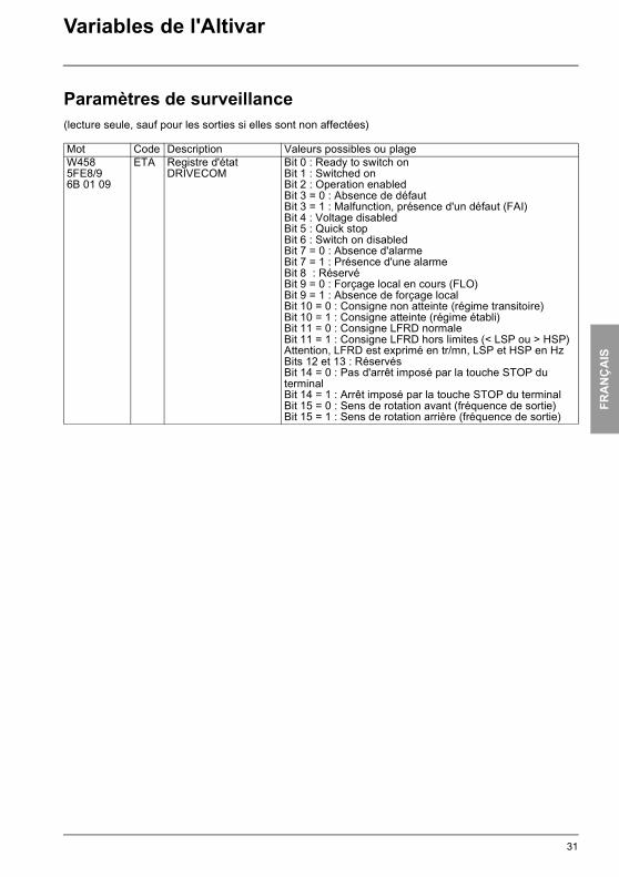
Mot Code Description Valeurs possibles ou plageW4585FE8/96B 01 09
ETA Registre d'état DRIVECOM
Bit 0 : Ready to switch onBit 1 : Switched onBit 2 : Operation enabledBit 3 = 0 : Absence de défautBit 3 = 1 : Malfunction, présence d'un défaut (FAI)Bit 4 : Voltage disabledBit 5 : Quick stopBit 6 : Switch on disabledBit 7 = 0 : Absence d'alarmeBit 7 = 1 : Présence d'une alarmeBit 8 : RéservéBit 9 = 0 : Forçage local en cours (FLO)Bit 9 = 1 : Absence de forçage localBit 10 = 0 : Consigne non atteinte (régime transitoire)Bit 10 = 1 : Consigne atteinte (régime établi)Bit 11 = 0 : Consigne LFRD normaleBit 11 = 1 : Consigne LFRD hors limites (< LSP ou > HSP) Attention, LFRD est exprimé en tr/mn, LSP et HSP en HzBits 12 et 13 : RéservésBit 14 = 0 : Pas d'arrêt imposé par la touche STOP du terminalBit 14 = 1 : Arrêt imposé par la touche STOP du terminalBit 15 = 0 : Sens de rotation avant (fréquence de sortie)Bit 15 = 1 : Sens de rotation arrière (fréquence de sortie)
31
FRA
NÇ
AIS
ATV38_58.book Page 32 Mardi, 11. février 2003 11:15 11
Variables de l'Altivar
Paramètres de surveillance(lecture seule, sauf pour les sorties si elles sont non affectées)
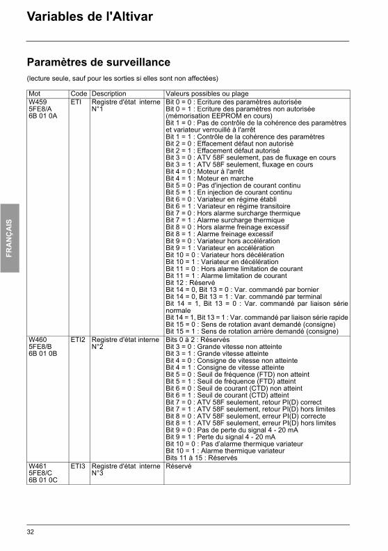
Mot Code Description Valeurs possibles ou plageW4595FE8/A6B 01 0A
ETI Registre d'état interne N°1
Bit 0 = 0 : Ecriture des paramètres autoriséeBit 0 = 1 : Ecriture des paramètres non autorisée (mémorisation EEPROM en cours)Bit 1 = 0 : Pas de contrôle de la cohérence des paramètres et variateur verrouillé à l'arrêtBit 1 = 1 : Contrôle de la cohérence des paramètresBit 2 = 0 : Effacement défaut non autoriséBit 2 = 1 : Effacement défaut autoriséBit 3 = 0 : ATV 58F seulement, pas de fluxage en coursBit 3 = 1 : ATV 58F seulement, fluxage en coursBit 4 = 0 : Moteur à l'arrêtBit 4 = 1 : Moteur en marcheBit 5 = 0 : Pas d'injection de courant continuBit 5 = 1 : En injection de courant continuBit 6 = 0 : Variateur en régime établiBit 6 = 1 : Variateur en régime transitoireBit 7 = 0 : Hors alarme surcharge thermiqueBit 7 = 1 : Alarme surcharge thermiqueBit 8 = 0 : Hors alarme freinage excessifBit 8 = 1 : Alarme freinage excessifBit 9 = 0 : Variateur hors accélérationBit 9 = 1 : Variateur en accélérationBit 10 = 0 : Variateur hors décélérationBit 10 = 1 : Variateur en décélérationBit 11 = 0 : Hors alarme limitation de courantBit 11 = 1 : Alarme limitation de courantBit 12 : RéservéBit 14 = 0, Bit 13 = 0 : Var. commandé par bornierBit 14 = 0, Bit 13 = 1 : Var. commandé par terminalBit 14 = 1, Bit 13 = 0 : Var. commandé par liaison sérienormaleBit 14 = 1, Bit 13 = 1 : Var. commandé par liaison série rapideBit 15 = 0 : Sens de rotation avant demandé (consigne)Bit 15 = 1 : Sens de rotation arrière demandé (consigne)
W4605FE8/B6B 01 0B
ETI2 Registre d'état interne N°2
Bits 0 à 2 : RéservésBit 3 = 0 : Grande vitesse non atteinteBit 3 = 1 : Grande vitesse atteinteBit 4 = 0 : Consigne de vitesse non atteinteBit 4 = 1 : Consigne de vitesse atteinteBit 5 = 0 : Seuil de fréquence (FTD) non atteintBit 5 = 1 : Seuil de fréquence (FTD) atteintBit 6 = 0 : Seuil de courant (CTD) non atteintBit 6 = 1 : Seuil de courant (CTD) atteintBit 7 = 0 : ATV 58F seulement, retour PI(D) correctBit 7 = 1 : ATV 58F seulement, retour PI(D) hors limitesBit 8 = 0 : ATV 58F seulement, erreur PI(D) correcteBit 8 = 1 : ATV 58F seulement, erreur PI(D) hors limitesBit 9 = 0 : Pas de perte du signal 4 - 20 mABit 9 = 1 : Perte du signal 4 - 20 mABit 10 = 0 : Pas d’alarme thermique variateurBit 10 = 1 : Alarme thermique variateurBits 11 à 15 : Réservés
W4615FE8/C6B 01 0C
ETI3 Registre d'état interne N°3
Réservé
32

FRA
NÇ
AIS
ATV38_58.book Page 33 Mardi, 11. février 2003 11:15 11
Variables de l'Altivar
Paramètres de surveillance(lecture seule, sauf pour les sorties si elles sont non affectées)
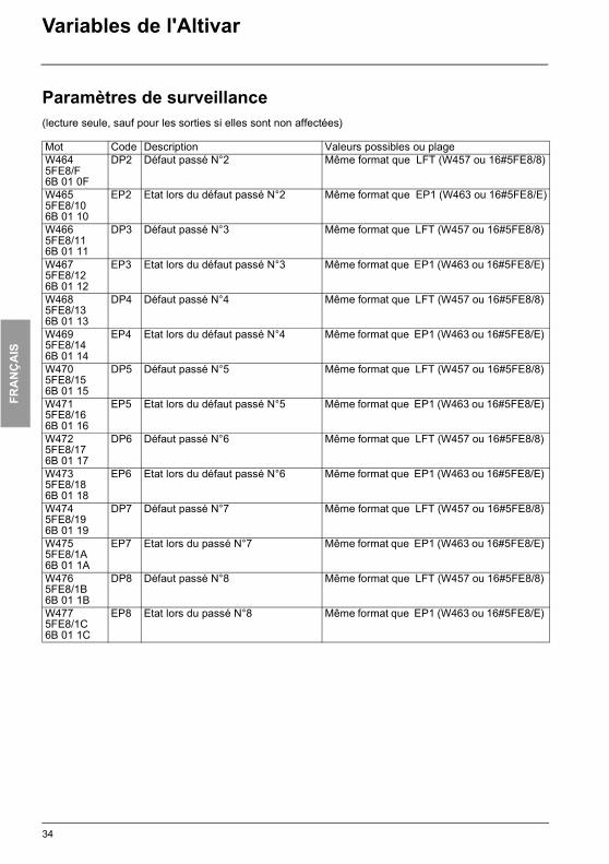
Mot Code Description Valeurs possibles ou plageW4625FE8/D6B 01 0D
DP1 Défaut passé N°1 Même format que LFT (W457 ou 16#5FE8/8)
W4635FE8/E6B 01 0E
EP1 Etat lors du défaut passé N°1
Bit 0 idem ETA. bit 1 :Bit 0 = 0 : Variateur non prêtBit 0 = 1 : Variateur prêt (RDY)Bit 1 idem ETA. bit 5 :Bit 1 = 0 : Arrêt d'urgence en coursBit 1 = 1 : Absence d'arrêt d'urgenceBit 2 idem ETA. bit 6 :Bit 2 = 0 : Etat ≠ Switch on disabled Bit 2 = 1 : Etat = Switch on disabled (ATV verrouillé, arrêt roue
libre)Bit 3 idem ETA. bit 9 : Bit 3 = 0 : Forçage local en cours (FLO)Bit 3 = 1 : Absence forçage localBit 4 idem ETA. bit 15 : Bit 4 = 0 : Sens de rotation avant (fréquence de sortie)Bit 4 = 1 : Sens de rotation arrière (fréquence de sortie)Bit 5 idem ETI.bit 4 :Bit 5 = 0 : Moteur à l'arrêtBit 5 = 1 : Moteur en marcheBit 6 idem ETI. bit 5 : Bit 6 = 0 : Pas d'injection de courant continuBit 6 = 1 : En injection de courant continuBit 7 idem ETI. bit 7 : Bit 7 = 0 : Hors alarme surcharge thermiqueBit 7 = 1 : Alarme surcharge thermiqueBit 8 idem ETI. bit 8 :Bit 8 = 0 : Hors alarme freinage excessifBit 8 = 1 : Alarme freinage excessifBit 9 idem ETI. bit 9 : Bit 9 = 0 : Variateur hors accélérationBit 9 = 1 : Variateur en accélérationBit 10 idem ETI. bit 10 : Bit 10 = 0 : Variateur hors décélérationBit 10 = 1 : Variateur en décélérationBit 11 idem ETI. bit 11 : Bit 11 = 0 : Hors alarme limitation de courantBit 11 = 1 : Alarme limitation de courant Bit 12 : RéservéBits 13 et 14 idem ETI. bits 13 et 14 : Bit 14 = 0, Bit 13 = 0 : Var. commandé par bornierBit 14 = 0, Bit 13 = 1 : Var. commandé par terminalBit 14 = 1, Bit 13 = 0 : Var. commandé par liaison série normaleBit 14 = 1, Bit 13 = 1 : Var. commandé par liaison série rapideBit 15 idem ETI. bit 15 :Bit 15 = 0 : Sens de rotation avant demandé (consigne)Bit 15 = 1 : Sens de rotation arrière demandé (consigne)
33
FRA
NÇ
AIS
ATV38_58.book Page 34 Mardi, 11. février 2003 11:15 11
Variables de l'Altivar
Paramètres de surveillance(lecture seule, sauf pour les sorties si elles sont non affectées)
Mot Code Description Valeurs possibles ou plageW4645FE8/F6B 01 0F
DP2 Défaut passé N°2 Même format que LFT (W457 ou 16#5FE8/8)
W4655FE8/106B 01 10
EP2 Etat lors du défaut passé N°2 Même format que EP1 (W463 ou 16#5FE8/E)
W4665FE8/116B 01 11
DP3 Défaut passé N°3 Même format que LFT (W457 ou 16#5FE8/8)
W4675FE8/126B 01 12
EP3 Etat lors du défaut passé N°3 Même format que EP1 (W463 ou 16#5FE8/E)
W4685FE8/136B 01 13
DP4 Défaut passé N°4 Même format que LFT (W457 ou 16#5FE8/8)
W4695FE8/146B 01 14
EP4 Etat lors du défaut passé N°4 Même format que EP1 (W463 ou 16#5FE8/E)
W4705FE8/156B 01 15
DP5 Défaut passé N°5 Même format que LFT (W457 ou 16#5FE8/8)
W4715FE8/166B 01 16
EP5 Etat lors du défaut passé N°5 Même format que EP1 (W463 ou 16#5FE8/E)
W4725FE8/176B 01 17
DP6 Défaut passé N°6 Même format que LFT (W457 ou 16#5FE8/8)
W4735FE8/186B 01 18
EP6 Etat lors du défaut passé N°6 Même format que EP1 (W463 ou 16#5FE8/E)
W4745FE8/196B 01 19
DP7 Défaut passé N°7 Même format que LFT (W457 ou 16#5FE8/8)
W4755FE8/1A6B 01 1A
EP7 Etat lors du passé N°7 Même format que EP1 (W463 ou 16#5FE8/E)
W4765FE8/1B6B 01 1B
DP8 Défaut passé N°8 Même format que LFT (W457 ou 16#5FE8/8)
W4775FE8/1C6B 01 1C
EP8 Etat lors du passé N°8 Même format que EP1 (W463 ou 16#5FE8/E)
34
FRA
NÇ
AIS
ATV38_58.book Page 35 Mardi, 11. février 2003 11:15 11
Variables de l'Altivar
Paramètres de surveillance(lecture seule, sauf pour les sorties si elles sont non affectées)
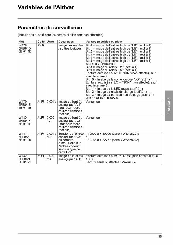
Mot Code Unité Description Valeurs possibles ou plageW4785FE8/1D6B 01 1D
IOLR Image des entrées / sorties logiques
Bit 0 = Image de l'entrée logique "LI1" (actif à 1)Bit 1 = Image de l'entrée logique "LI2" (actif à 1)Bit 2 = Image de l'entrée logique "LI3" (actif à 1)Bit 3 = Image de l'entrée logique "LI4" (actif à 1)Bit 4 = Image de l'entrée logique "LI5" (actif à 1)Bit 5 = Image de l'entrée logique "LI6" (actif à 1)Bits 6 et 7 : RéservésBit 8 = Image du relais "R1" (actif à 1)Bit 9 = Image du relais "R2" (actif à 1)Ecriture autorisée si R2 = "NON" (non affecté), sauf avec Interbus-S.Bit 10 = Image de la sortie logique "LO" (actif à 1)Ecriture autorisée si LO = "NON" (non affecté), sauf avec Interbus-S.Bit 11 = Image de la LED rouge (actif à 1)Bit 12 = Image du relais de charge (actif à 1)Bit 13 = Image du transistor de freinage (actif à 1)Bits 14 et 15 : Réservés
W4795FE8/1E6B 01 1E
AI1R 0,001V Image de l'entrée analogique "AI1" (grandeur réelle calibrée et mise à l'échelle)
Valeur lue
W4805FE8/1F6B 01 1F
AI2R 0,002 mA
Image de l'entrée analogique "AI2" (grandeur réelle calibrée et mise à l'échelle)
Valeur lue
W4815FE8/206B 01 20
AI3R 0,001Vou 1
Tension de l'entrée analogique "AI3" ou nombre d'impulsions sur l'entrée codeur, selon le type de carte E/S
- 10000 à + 10000 (carte VW3A58201)ou- 32768 à + 32767 (carte VW3A58202)
W4825FE8/216B 01 21
AOR 0,002 mA
Image de la sortie analogique "AO"
Ecriture autorisée si AO = "NON" (non affectée) : 0 à 10000Lecture seule si affectée : Valeur lue
35

FRA
NÇ
AIS
ATV38_58.book Page 36 Mardi, 11. février 2003 11:15 11
Variables de l'Altivar
Paramètres de surveillance(lecture seule, sauf pour les sorties si elles sont non affectées)
Le mot W493 n'existe que pour les ATV 58F
Mot Code Unité Description Valeurs possibles ou plageW4865FE8/256B 01 25
CUS Entrées / sorties réaffectées(Macro config. = CUS)
0 = NON1 = OUI
W4875FE8/266B 01 26
OTR 1% Couple moteur(sauf ATV 38)
Valeur lue100% = couple nominal moteur
W4885FE8/276B 01 27
FRO 0,1Hz Sortie rampe (signée)
Valeur lue
W4915FE8/2A6B 01 2A
OPR 1% Puissance de sortie
Valeur lue100% = puissance nominale moteur
W4925FE8/2B6B 01 2B
AO1R
0,002 mA
Image de la sortie analogique "AO1"
Ecriture autorisée si AO1 = "NON"(non affectée) : 0 à 10000Lecture seule si affectée = valeur lue
W4935FE8/2C6B 01 2C
UOP 0,1 V Tension appliquée au moteur
Valeur lue
W4945FE8/2D6B 01 2D
APH 1 kWhou1MWh
Energie consommée
Si bit 15 = 0, consommation en kWh sur bits 0 à 14Si bit 15 = 1, consommation en MWh sur bits 0 à 14
W4955FE8/2E6B 01 2E
RTH 1h Temps de fonction-nement en heures (moteur sous tension)
Valeur lue
36
FRA
NÇ
AIS
ATV38_58.book Page 37 Mardi, 11. février 2003 11:15 11
Variables de l'Altivar
Paramètres "DRIVECOM"
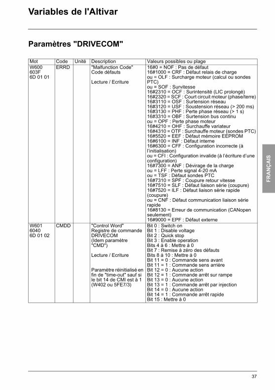
Mot Code Unité Description Valeurs possibles ou plageW600603F6D 01 01
ERRD "Malfunction Code"Code défauts
Lecture / Ecriture
16#0 = NOF : Pas de défaut16#1000 = CRF : Défaut relais de chargeou = OLF : Surcharge moteur (calcul ou sondes PTC)ou = SOF : Survitesse16#2310 = OCF : Surintensité (LIC prolongé)16#2320 = SCF : Court circuit moteur (phase/terre)16#3110 = OSF : Surtension réseau16#3120 = USF : Soustension réseau (> 200 ms)16#3130 = PHF : Perte phase réseau (> 1 s)16#3310 = OBF : Surtension bus continuou = OPF : Perte phase moteur16#4210 = OHF : Surchauffe variateur16#4310 = OTF : Surchauffe moteur (sondes PTC)16#5520 = EEF : Défaut mémoire EEPROM16#6100 = INF : Défaut interne16#6300 = CFF : Configuration incorrecte (à l’initialisation)ou = CFI : Configuration invalide (à l’écriture d’une configuration)16#7300 = ANF : Dévirage de la chargeou = LFF : Perte signal 4-20 mAou = TSF : Défaut sondes PTC16#7310 = SPF : Coupure retour vitesse16#7510 = SLF : Défaut liaison série (coupure)16#7520 = ILF : Défaut liaison série rapide (coupure)ou = CNF : Défaut communication liaison série rapide16#8130 = Erreur de communication (CANopen seulement)16#9000 = EPF : Défaut externe
W60160406D 01 02
CMDD "Control Word"Registre de commande DRIVECOM(Idem paramètre "CMD")
Lecture / Ecriture
Paramètre réinitialisé en fin de "time-out" sauf si le bit 14 de CMI est à 1 (W402 ou 5FE7/3)
Bit 0 : Switch onBit 1 : Disable voltageBit 2 : Quick stopBit 3 : Enable operationBits 4 à 6 : Mettre à 0Bit 7 : Remise à zéro des défautsBits 8 à 10 : Mettre à 0Bit 11 = 0 : Commande sens avantBit 11 = 1 : Commande sens arrièreBit 12 = 0 : Aucune actionBit 12 = 1 : Commande arrêt sur rampeBit 13 = 0 : Aucune actionBit 13 = 1 : Commande arrêt par injectionBit 14 = 0 : Aucune actionBit 14 = 1 : Commande arrêt rapideBit 15 : Mettre à 0
37
FRA
NÇ
AIS
ATV38_58.book Page 38 Mardi, 11. février 2003 11:15 11
Variables de l'Altivar
Paramètres "DRIVECOM"
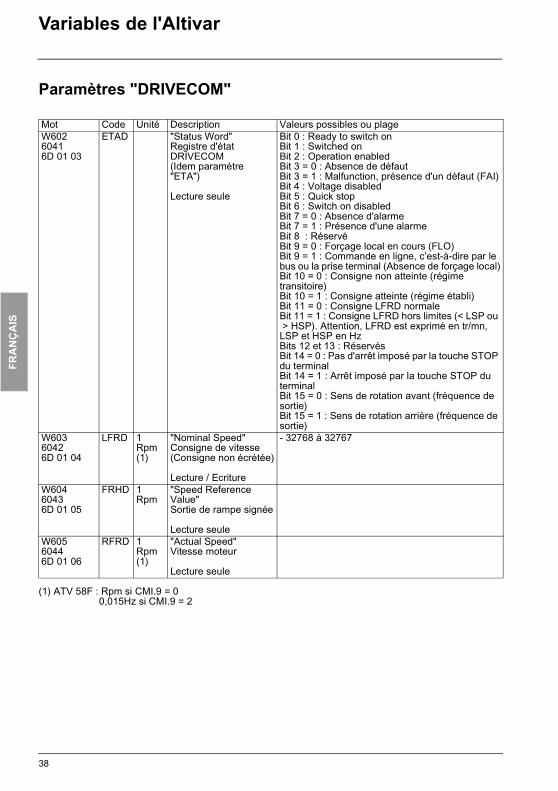
(1) ATV 58F : Rpm si CMI.9 = 00,015Hz si CMI.9 = 2
Mot Code Unité Description Valeurs possibles ou plageW60260416D 01 03
ETAD "Status Word"Registre d'état DRIVECOM(Idem paramètre "ETA")
Lecture seule
Bit 0 : Ready to switch onBit 1 : Switched onBit 2 : Operation enabledBit 3 = 0 : Absence de défautBit 3 = 1 : Malfunction, présence d'un défaut (FAI)Bit 4 : Voltage disabledBit 5 : Quick stopBit 6 : Switch on disabledBit 7 = 0 : Absence d'alarmeBit 7 = 1 : Présence d'une alarmeBit 8 : RéservéBit 9 = 0 : Forçage local en cours (FLO)Bit 9 = 1 : Commande en ligne, c’est-à-dire par le bus ou la prise terminal (Absence de forçage local)Bit 10 = 0 : Consigne non atteinte (régime transitoire)Bit 10 = 1 : Consigne atteinte (régime établi)Bit 11 = 0 : Consigne LFRD normaleBit 11 = 1 : Consigne LFRD hors limites (< LSP ou > HSP). Attention, LFRD est exprimé en tr/mn, LSP et HSP en HzBits 12 et 13 : RéservésBit 14 = 0 : Pas d'arrêt imposé par la touche STOP du terminalBit 14 = 1 : Arrêt imposé par la touche STOP du terminalBit 15 = 0 : Sens de rotation avant (fréquence de sortie)Bit 15 = 1 : Sens de rotation arrière (fréquence de sortie)
W60360426D 01 04
LFRD 1 Rpm(1)
"Nominal Speed"Consigne de vitesse(Consigne non écrétée)
Lecture / Ecriture
- 32768 à 32767
W60460436D 01 05
FRHD 1 Rpm
"Speed Reference Value"Sortie de rampe signée
Lecture seuleW60560446D 01 06
RFRD 1 Rpm(1)
"Actual Speed"Vitesse moteur
Lecture seule
38
FRA
NÇ
AIS
ATV38_58.book Page 39 Mardi, 11. février 2003 11:15 11
Variables de l'Altivar
Paramètres "DRIVECOM"
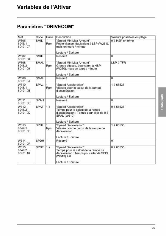
Mot Code Unité Description Valeurs possibles ou plageW6066046/16D 01 07
SMIL 1 Rpm
"Speed Min Max Amount"Petite vitesse, équivalent à LSP (W251), mais en tours / minute
Lecture / Ecriture
0 à HSP en tr/mn
W6076D 01 08
SMIH Réservé 0
W6086046/26D 01 09
SMAL 1 Rpm
"Speed Min Max Amount"Grande vitesse, équivalent à HSP (W250), mais en tours / minute
Lecture / Ecriture
LSP à TFR
W6096D 01 0A
SMAH Réservé 0
W6106048/16D 01 0B
SPAL 1 Rpm
"Speed Acceleration"Vitesse pour le calcul de la rampe d’accélération
Lecture / Ecriture
1 à 65535
W6116D 01 0C
SPAH Réservé 0
W6126048/26D 01 0D
SPAT 1 s "Speed Acceleration"Temps pour le calcul de la rampe d’accélération : Temps pour aller de 0 à SPAL (W610)
Lecture / Ecriture
0 à 65535
W6136049/16D 01 0E
SPDL 1 Rpm
"Speed Deceleration"Vitesse pour le calcul de la rampe de décélération
Lecture / Ecriture
1 à 65535
W6146D 01 0F
SPDH Réservé 0
W6156049/26D 01 10
SPDT 1 s "Speed Deceleration"Temps pour le calcul de la rampe de décélération : Temps pour aller de SPDL (W613) à 0
Lecture / Ecriture
0 à 65535
39

FRA
NÇ
AIS
ATV38_58.book Page 40 Mardi, 11. février 2003 11:15 11
Index alphabétique par codes
Code Adresse Code Adresse Code Adresse Code AdresseAC2 W260 DTS W285 LI2 W101 SIG W298ACC W252 ENC W78 LI3 W102 SLP W259ADC W67 EP1 W463 LI4 W103 SMAL W608ADD W10 EP2 W465 LI5 W104 SMIL W606AI1R W479 EP3 W467 LI6 W105 SP2 W264AI2 W107 EP4 W469 LO W111 SP3 W265AI2R W480 EP5 W471 LSP W251 SP4 W266AI3 W108 EP6 W473 NCR W54 SP5 W267AI3R W481 EP7 W475 NLD W61 SP6 W268AO W112 EP8 W477 NRD W60 SP7 W269AO1 W113 EPL W160 NSP W56 SP8 W316AO1R W492 ERRD W600 OPL W151 SPAL W610AOH W15 ETA W458 OPR W491 SPAT W612AOL W14 ETAD W602 ORT W11 SPC W70AOR W482 ETI W459 OTR W487 SPD W452APH W494 ETI2 W460 PAH W301 SPDL W613ATR W150 ETI3 W461 PAL W300 SPDT W615BEN W274 F2D W314 PCC W69 SPG W297BER W66 FBS W281 PER W302 SRP W292BET W276 FDB W73 PFL W256 SSL W77BIP W290 FFT W313 PGI W76 STA W257BRA W64 FLG W255 PGT W71 STP W156BRL W273 FLR W155 PI2 W308 STR W9BRT W275 FLU W74 PI3 W309 STT W79BSP W13 FRH W450 PIC W287 TA1 W293CFG W3 FRHD W604 PISP W403 TA2 W294CIC W1 FRO W488 PLB W307 TA3 W295CLI W72 FRS W53 PLR W306 TA4 W296CMD W400 FRT W65 PLS W68 TBR W16CMDD W601 FTD W284 PRG W310 TCC W6CMI W402 HSP W250 PSP W304 TCT W7COS W57 IBR W277 PSR W305 TDC W271CRH W5 IDC W270 PST W8 TFR W52CRL W4 INR W291 R2 W110 THD W456CTD W282 IOLR W478 RDG W303 THR W455CTR W75 IPL W152 REO W299 THT W153CUS W486 ITH W258 RFR W451 TL2 W278DCF W63 JF2 W311 RFRD W605 TLI W58DE2 W261 JF3 W312 RIG W280 TLS W272DEC W253 JGT W263 RIN W12 TTD W283DP1 W462 JOG W262 RPG W279 TUN W59DP2 W464 JPF W286 RPR W17 UFR W254DP3 W466 LCR W453 RPT W62 ULN W454DP4 W468 LFF W159 RST W158 UNS W55DP5 W470 LFL W154 RTH W495 UOP W493DP6 W472 LFR W401 SDC W288 USC W289DP7 W474 LFRD W603 SDD W157DP8 W476 LFT W457 SFR W51DTD W315 LI1 W100 SFT W50
40

FRA
NÇ
AIS
ATV38_58.book Page 41 Mardi, 11. février 2003 11:15 11
41

42
ENG
LISH
While every precaution has been taken in the preparation of this document, Schneider Electric SA assumesno liability for any omissions or errors it may contain, nor for any damages resulting from the application oruse of the information herein.
The products described in this document may be changed or modified at any time, either from a technicalpoint of view or in the way they are operated. Their description can in no way be considered contractual.
Since its original launch, the Altivar 58 has benefited from additional functions and the introduction of theATV 58F and ATV 38. This document takes account of these additions. It is still valid for our earliest devicesbut contains descriptions of parameters which are not included in those drives.
ATV38_58.book Page 42 Mardi, 11. février 2003 11:15 11
43
ENG
LISH
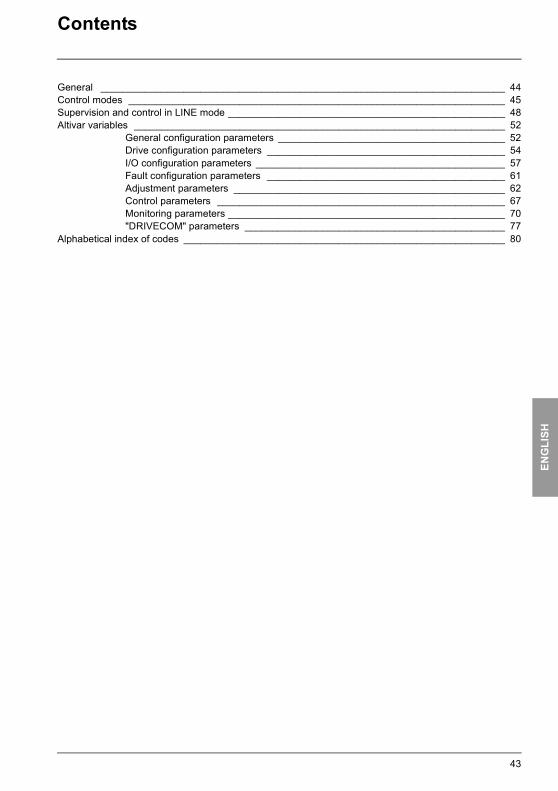
Contents
General _________________________________________________________________________ 44Control modes ____________________________________________________________________ 45Supervision and control in LINE mode __________________________________________________ 48Altivar variables ___________________________________________________________________ 52
General configuration parameters _________________________________________ 52Drive configuration parameters ___________________________________________ 54I/O configuration parameters _____________________________________________ 57Fault configuration parameters ___________________________________________ 61Adjustment parameters _________________________________________________ 62Control parameters ____________________________________________________ 67Monitoring parameters __________________________________________________ 70"DRIVECOM" parameters _______________________________________________ 77
Alphabetical index of codes __________________________________________________________ 80
ATV38_58.book Page 43 Mardi, 11. février 2003 11:15 11
ENG
LISH
ATV38_58.book Page 44 Mardi, 11. février 2003 11:15 11
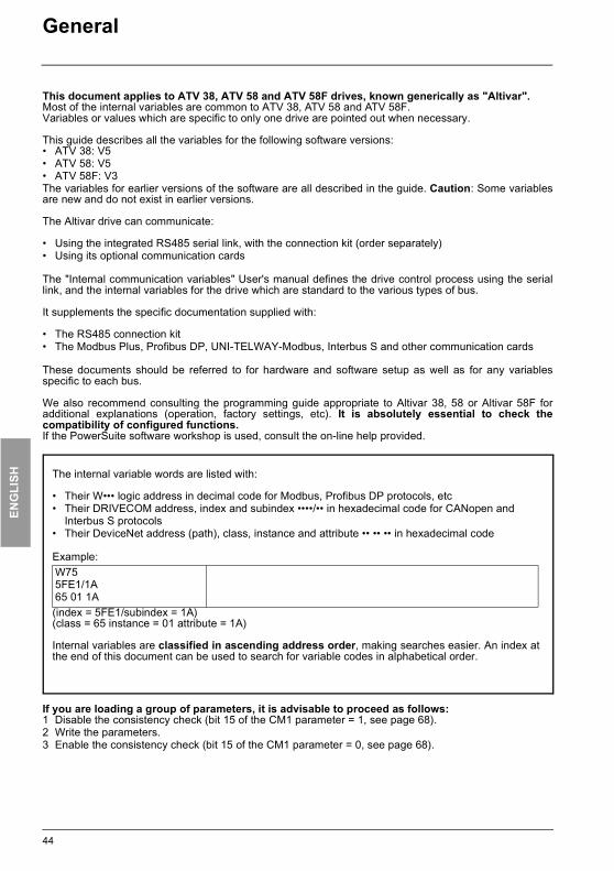
General
This document applies to ATV 38, ATV 58 and ATV 58F drives, known generically as "Altivar".Most of the internal variables are common to ATV 38, ATV 58 and ATV 58F.Variables or values which are specific to only one drive are pointed out when necessary.
This guide describes all the variables for the following software versions:• ATV 38: V5• ATV 58: V5• ATV 58F: V3The variables for earlier versions of the software are all described in the guide. Caution: Some variablesare new and do not exist in earlier versions. The Altivar drive can communicate:
• Using the integrated RS485 serial link, with the connection kit (order separately)• Using its optional communication cards
The "Internal communication variables" User's manual defines the drive control process using the seriallink, and the internal variables for the drive which are standard to the various types of bus.
It supplements the specific documentation supplied with:
• The RS485 connection kit • The Modbus Plus, Profibus DP, UNI-TELWAY-Modbus, Interbus S and other communication cards
These documents should be referred to for hardware and software setup as well as for any variablesspecific to each bus.
We also recommend consulting the programming guide appropriate to Altivar 38, 58 or Altivar 58F foradditional explanations (operation, factory settings, etc). It is absolutely essential to check thecompatibility of configured functions.If the PowerSuite software workshop is used, consult the on-line help provided.
If you are loading a group of parameters, it is advisable to proceed as follows:1 Disable the consistency check (bit 15 of the CM1 parameter = 1, see page 68).2 Write the parameters.3 Enable the consistency check (bit 15 of the CM1 parameter = 0, see page 68).
The internal variable words are listed with:
• Their W••• logic address in decimal code for Modbus, Profibus DP protocols, etc• Their DRIVECOM address, index and subindex ••••/•• in hexadecimal code for CANopen and
Interbus S protocols• Their DeviceNet address (path), class, instance and attribute •• •• •• in hexadecimal code
Example:
(index = 5FE1/subindex = 1A)(class = 65 instance = 01 attribute = 1A)
Internal variables are classified in ascending address order, making searches easier. An index atthe end of this document can be used to search for variable codes in alphabetical order.
W755FE1/1A65 01 1A
44
ENG
LISH
ATV38_58.book Page 45 Mardi, 11. février 2003 11:15 11
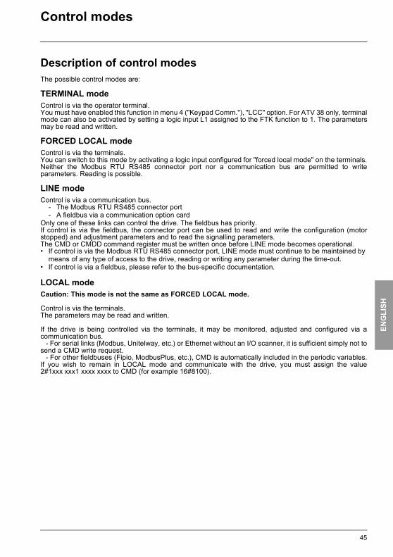
Control modes
Description of control modesThe possible control modes are:
TERMINAL modeControl is via the operator terminal.You must have enabled this function in menu 4 ("Keypad Comm."), "LCC" option. For ATV 38 only, terminalmode can also be activated by setting a logic input L1 assigned to the FTK function to 1. The parametersmay be read and written.
FORCED LOCAL modeControl is via the terminals.You can switch to this mode by activating a logic input configured for "forced local mode" on the terminals.Neither the Modbus RTU RS485 connector port nor a communication bus are permitted to writeparameters. Reading is possible.
LINE modeControl is via a communication bus.
- The Modbus RTU RS485 connector port - A fieldbus via a communication option card
Only one of these links can control the drive. The fieldbus has priority.If control is via the fieldbus, the connector port can be used to read and write the configuration (motorstopped) and adjustment parameters and to read the signalling parameters.The CMD or CMDD command register must be written once before LINE mode becomes operational. • If control is via the Modbus RTU RS485 connector port, LINE mode must continue to be maintained by
means of any type of access to the drive, reading or writing any parameter during the time-out.• If control is via a fieldbus, please refer to the bus-specific documentation.
LOCAL modeCaution: This mode is not the same as FORCED LOCAL mode.
Control is via the terminals.The parameters may be read and written.
If the drive is being controlled via the terminals, it may be monitored, adjusted and configured via acommunication bus.
- For serial links (Modbus, Unitelway, etc.) or Ethernet without an I/O scanner, it is sufficient simply not tosend a CMD write request.
- For other fieldbuses (Fipio, ModbusPlus, etc.), CMD is automatically included in the periodic variables.If you wish to remain in LOCAL mode and communicate with the drive, you must assign the value2#1xxx xxx1 xxxx xxxx to CMD (for example 16#8100).
45
ENG
LISH
ATV38_58.book Page 46 Mardi, 11. février 2003 11:15 11
Control modes
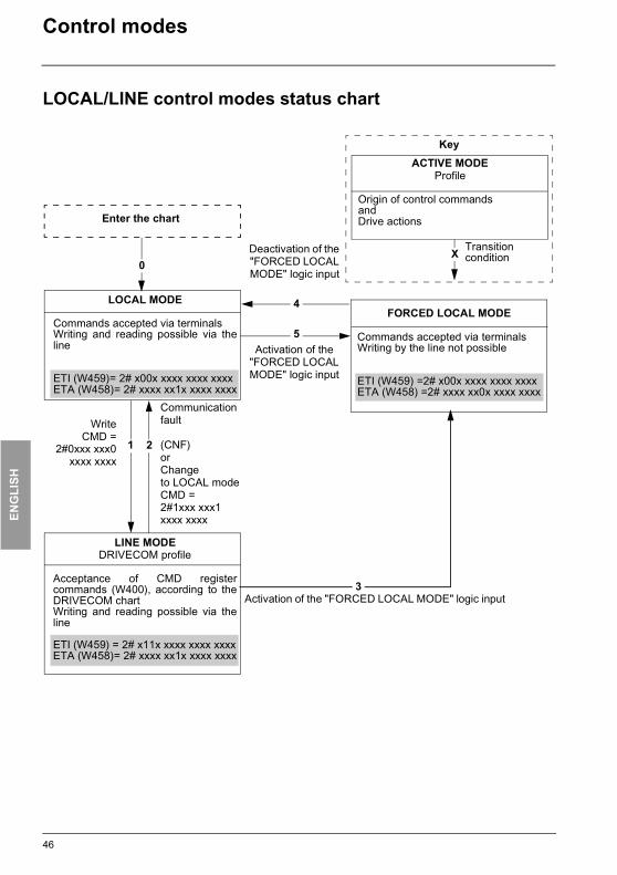
LOCAL/LINE control modes status chart
LINE MODEDRIVECOM profile
Acceptance of CMD registercommands (W400), according to theDRIVECOM chartWriting and reading possible via theline
ETI (W459) = 2# x11x xxxx xxxx xxxxETA (W458)= 2# xxxx xx1x xxxx xxxx
LOCAL MODE
Commands accepted via terminalsWriting and reading possible via theline
ETI (W459)= 2# x00x xxxx xxxx xxxxETA (W458)= 2# xxxx xx1x xxxx xxxx
FORCED LOCAL MODE
Commands accepted via terminals Writing by the line not possible
ETI (W459) =2# x00x xxxx xxxx xxxxETA (W458) =2# xxxx xx0x xxxx xxxx
Enter the chart
KeyACTIVE MODE
Profile
Origin of control commandsandDrive actions
Communication fault (CNF) orChangeto LOCAL modeCMD = 2#1xxx xxx1xxxx xxxx
Deactivation of the "FORCED LOCAL MODE" logic input
Activation of the "FORCED LOCAL MODE" logic input
WriteCMD =
2#0xxx xxx0xxxx xxxx
Activation of the "FORCED LOCAL MODE" logic input
Transitioncondition
2
3
1
0X
4
5
46
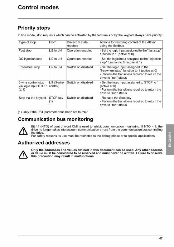
ENG
LISH
ATV38_58.book Page 47 Mardi, 11. février 2003 11:15 11
Control modes
Priority stopsIn line mode, stop requests which can be activated by the terminals or by the keypad always have priority:
(1) Only if the PST parameter has been set to "NO"
Communication bus monitoringBit 14 (NTO) of control word CMI is used to inhibit communication monitoring. If NTO = 1, thedrive no longer takes into account communication errors from the communication bus controllingthe drive.For safety reasons its use must be restricted to the debug phase or to special applications.
Authorized addressesOnly the addresses and values defined in this document can be used. Any other addressor value must be considered to be reserved and must never be written. Failure to observethis precaution may result in malfunctions.
Type of stop From Drivecom state reached
Actions for restoring control of the Altivar using the fieldbus
Fast stop LI2 to LI4 Operation enabled - Set the logic input assigned to the "fast stop" function to 1 (active at 0)
DC injection stop LI2 to LI4 Operation enabled - Set the logic input assigned to the "injection stop" function to 0 (active at 1)
Freewheel stop LI2 to LI4 Switch on disabled - Set the logic input assigned to the "freewheel stop" function to 1 (active at 0) - Perform the transitions required to return the drive to "run" status
3-wire control stop via logic input STOP (LI1)
LI1 (3-wire control)
Switch on disabled - Set the logic input assigned to STOP to 1 (active at 0) - Perform the transitions required to return the drive to "run" status
Stop via the keypad STOP key(1)
Switch on disabled - Release the Stop key- Perform the transitions required to return the drive to "run" status
47

ENG
LISH
ATV38_58.book Page 48 Mardi, 11. février 2003 11:15 11
Supervision and control in LINE mode
DRIVECOM status chart
��� ����� �� ��� ����� ������ ��
��� � ������
����� � ����� � ���
����� ����������
����� �����
��� � ������
� ����
��� � ������
����!��
"����#�
��� � ������
��
$��%& ����
��� � �����'
����!�� "����#�
��� � ������
��
(����%���� ��
� %���#������
����(����
)(���� ������*
��
��+, &�- �
���(���
��
��+, �� ���(����
�����
�������� ����� �������"� ������ ������ �� ���
��� � ������
.��� ���(��� �����-.
��������
%�����
��� � ������
��� ��� ����
�����������
�������� ������
��� � ������
�������������� �����-
��� � ������
���� �� ����� ���-
��� � ����'/
.0�1.
��
!
�
���� �� ���"������ ��%&�
��� � ����2�
.3��.
����� �� ��� ����� �����#
��� � ����'
.3��.
#���$ ��% �������(��#�%- ����
��� � �����4
.0�1� ���� ��5.
& '
�(
�)
��!��
��������
��� � ������
��!��
��������
��� � ������ ����!��
��������
��� � �����4
�%������� ���"������ ���#
��� � ����'4
.063� 0�1� 777.
���(���� 8
��� � ����'4 8 3��(�� ���� ��
9 ������ ��������� ���� ���% �
��� � ����'4 8 0�"���� ��������� ���� ���% �
��� � ���''4 8 ������ ��������� ��� �� ���
��� � ���''4 8 0�"���� ��������� ��� �� ���
��� � ������ 8 ������ ��������
��� � ������ 8 0�"���� ��������
��� � �� ��� 8 ���� � ��(�
��� � ��'��� 8 �� �:�%��� ����
��� � ��2��� 8 ���� ����
( )
��
�&
����% �
��� � �����4� ����
��� � ������
� ����
��� � ������
$��%& ����
��� � �����5
�
��
*
+
,
����!��
"����#�
��� � ������
��
(����%���� ��
� %���#������
����(����
)(���� ������*
�
�- .+������� ��!��. ������ ��%��� .$��%& ����. � ����� ��� ����
����!�� "����#�
��� � ������
��
(����%���� ��
� %���#������
����(����
)(���� ������*
��
��+, &�- �
���(���
��
��+, �� ���(����
48
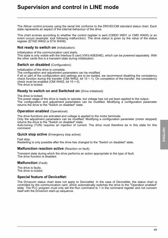
ENG
LISH
ATV38_58.book Page 49 Mardi, 11. février 2003 11:15 11
Supervision and control in LINE mode
The Altivar control process using the serial link conforms to the DRIVECOM standard status chart. Eachstate represents an aspect of the internal behaviour of the drive.
This chart evolves according to whether the control register is sent (CMDD W601 or CMD W400) or anevent occurs (example: lock following malfunction). The drive status is given by the value of the statusregister (ETAD W602 or ETA W458).
Not ready to switch on (Initialization):Initialization of the communication card starts.This state is only visible with the Interbus-S card (VW3-A58304E), which can be powered separately. Withthe other cards this is a transient state during initialization.
Switch on disabled (Configuration):Initialization of the drive is complete.The configuration and adjustment parameters can be modified.If all or part of the configuration and settings are to be loaded, we recommend disabling the consistencycheck function during the transfer (CMI W402, bit 15 = 1). On completion of the transfer, the consistencycheck must be enabled (CMI W402, bit 15 = 0).The drive is locked.
Ready to switch on and Switched on (Drive initialized):The drive is locked.The power stage of the drive is ready to operate, but voltage has not yet been applied to the output.The configuration and adjustment parameters can be modified. Modifying a configuration parameterreturns the drive to the "Switch on disabled" state.
Operation enabled (Operational):The drive functions are activated and voltage is applied to the motor terminals.Only the adjustment parameters can be modified. Modifying a configuration parameter (motor stopped)returns the drive to the "Switch on disabled" state.Auto-tuning (TUN) requires an injection of current. The drive must therefore be in this state for thiscommand.
Quick stop active (Emergency stop active):Fast stop.Restarting is only possible after the drive has changed to the "Switch on disabled" state.
Malfunction reaction active (Reaction on fault):Transient state during which the drive performs an action appropriate to the type of fault.The drive function is disabled.
Malfunction (Fault):The drive is faulty.The drive is locked.
Special feature of DeviceNet:The Drivecom status chart does not apply to DeviceNet. In the case of DeviceNet, the status chart iscontrolled by the communication card, which automatically switches the drive to the "Operation enabled"state. The PLC program must only set the Run command to 1 in the command register and not concernitself with the Drivecom start-up sequence.
49

ENG
LISH
ATV38_58.book Page 50 Mardi, 11. février 2003 11:15 11
Supervision and control in LINE mode
CMDD (W601) or CMD (W400) control register
x: state is not significant0 → 1: switch from 0 to 1
Bit 7 Bit 6 Bit 5 Bit 4 Bit 3 Bit 2 Bit 1 Bit 0
Fault reset 0 0 0 Enable operation
Quick stop(active at 0)
Disable voltage
(active at 0)Switch on
Bit 15 Bit 14 Bit 13 Bit 12 Bit 11 Bit 10 Bit 9 Bit 8
0 Fast stopDC
injection stop
Stop on ramp
Forward/Reverse 0 0 0
Command Transition address Final state
Bit 7 Bit 3 Bit 2 Bit 1 Bit 0 Typical value of CMDD (W601) or
CMD (W400)Reset Enable operation
Quick stop
Disable voltage
Switch on
Shut down 2, 6, 8 Ready to switch on x x 1 1 0 16#0006
Switch on 3 Switched on x x 1 1 1 16#0007
Enable operation 4 Operation
enabled x 1 1 1 1 16#000F
Disable operation 5 Switched
on x 0 1 1 1 16#0007
Disable voltage
7, 9, 10, 12
Switch on disabled x x x 0 x 16#0000
Quick stop11 Quick stop
activex x 0 1 x
16#000Bor
16#00027, 10 Switch on disabled
Fault reset 15 Switch on disabled 0 → 1 x x x x 16#0080
50

ENG
LISH
ATV38_58.book Page 51 Mardi, 11. février 2003 11:15 11
Supervision and control in LINE mode
ETAD (W602) or ETA (W458) status register
x: state is not significant
(1) Bit 4 of the ETA status register corresponds to "Voltage disabled".
Bit 7 Bit 6 Bit 5 Bit 4 Bit 3 Bit 2 Bit 1 Bit 0
Alarm Switch on disabled
Quick stopactive at 0
0(1) Malfunction Operation
enabledSwitched
onReady to switch on
Bit 15 Bit 14 Bit 13 Bit 12 Bit 11 Bit 10 Bit 9 Bit 8
Direction of rotation
Stop via STOP key 0 0 Reference
exceededReference reached
Forced local mode(active at 0)
0
StateBit 6 Bit 5 Bit 3 Bit 2 Bit 1 Bit 0 ETA (W458)
masked by16#006F
Switch on disabled Quick stop Malfunction Operation
enabledSwitched
onReady to switch on
Not ready to switch on 0 x 0 0 0 0 16#0000
16#0020Switch on disabled 1 x 0 0 0 0 16#0040
16#0060Ready to switch on 0 1 0 0 0 1 16#0021
Switched on 0 1 0 0 1 1 16#0023Operation enabled 0 1 0 1 1 1 16#0027
Malfunction 0 x 1 0 0 0 16#000816#0028
Malfunction reaction active 0 x 1 1 1 1 16#000F
16#002FQuick stop active 0 0 0 1 1 1 16#0007
51
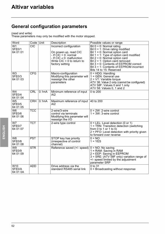
ENG
LISH
ATV38_58.book Page 52 Mardi, 11. février 2003 11:15 11
Altivar variables
General configuration parameters(read and write)These parameters may only be modified with the motor stopped.
Word Code Unit Description Possible values or rangeW15FE0/164 01 01
CIC Incorrect configuration
On power-up, read CIC- If CIC = 0: normal- If CIC ≠ 0: malfunctionWrite CIC = 0 to return to factory setting
Bit 0 = 0: Normal ratingBit 0 = 1: Drive rating modifiedBit 1 = 0: Normal option cardBit 1 = 1: Type of option card modifiedBit 2 = 0: Normal option cardBit 2 = 1: Option card removedBit 3 = 0: Contents of EEPROM correctBit 3 = 1: Contents of EEPROM incorrectBits 14 to 15: Reserved
W35FE0/364 01 03
CFG Macro-configurationModifying this parameter will reassign the other parameters
0 = HDG: Handling1 = GEN: General use2 = VT: Variable torqueATV 38: Value 2 only (cannot be configured) ATV 58F: Values 0 and 1 onlyATV 58: Values 0, 1 and 2
W45FE0/464 01 04
CRL 0.1mA Minimum reference of input AI2
0 to 200
W55FE0/564 01 05
CRH 0.1mA Maximum reference of input AI2
40 to 200
W65FE0/664 01 06
TCC 2-wire/3-wirecontrol via terminalsModifying this parameter will reassign the I/O
0 = 2W: 2-wire control 1 = 3W: 3-wire control
W75FE0/764 01 07
TCT 2-wire type control 0 = LEL: Level detection (0 or 1)1 = TRN: Transition detection (switching from 0 to 1 or 1 to 0)2 = PFO: Level detection with priority given to forward over reverse
W85FE0/864 01 08
PST STOP key has priority (irrespective of control channel)
0 = NO1 = YES
W95FE0/964 01 09
STR Reference saved (+/- speed) 0 = NO: No saving1 = RAM: Saving in RAM2 = EEP: Saving in EEPROM3 = SRE: (ATV 58F only) variation range of +/- speed limited by the adjustment parameter SRP
W105FE0/A64 01 0A
ADD Drive address via the standard RS485 serial link
0 to 310 = Broadcasting without response
52
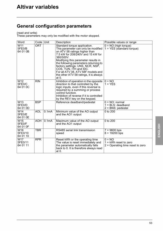
ENG
LISH
ATV38_58.book Page 53 Mardi, 11. février 2003 11:15 11
Altivar variables
General configuration parameters(read and write)These parameters may only be modified with the motor stopped.
Word Code Unit Description Possible values or rangeW115FE0/B64 01 0B
ORT Standard torque application.This parameter can only be modified on ATV 58 ratings higher than 7.5 kW for 208/240V and 15 kW for 380/500V. Modifying this parameter results in the following parameters returning to factory settings: UNS, NCR, NSP, COS, TUN, ITH and IDC.For all ATV 38, ATV 58F models and the other ATV 58 ratings, it is always at 0.
0 = NO (high torque)1 = YES (standard torque)
W125FE0/C64 01 0C
RIN Inhibition of operation in the opposite direction to that controlled by the logic inputs, even if this reversal is required by a summing or process control function.Inhibition of reverse if it is controlled by the REV key on the keypad.
0 = NO1 = YES
W135FE0/D64 01 0D
BSP Reference deadband/pedestal 0 = NO: normal1 = BLS: deadband2 = BNS: pedestal
W145FE0/E64 01 0E
AOL 0.1mA Minimum value of the AO outputand the AO1 output
0 to 200
W155FE0/F64 01 0F
AOH 0.1mA Maximum value of the AO outputand the AO1 output
0 to 200
W165FE0/1064 01 10
TBR RS485 serial link transmission speed
7 = 9600 bps8 = 19200 bps
W175FE0/1164 01 11
RPR Reset kWh or the operating timeThe value is reset immediately and the parameter automatically falls back to 0. It is therefore always read at 0.
0 = NO1 = kWh reset to zero2 = Operating time reset to zero
53

ENG
LISH
ATV38_58.book Page 54 Mardi, 11. février 2003 11:15 11
Altivar variables
Drive configuration parameters(read and write)These parameters may only be modified with the motor stopped.
Word Code Unit Description Possible values or rangeW505FE1/165 01 01
SFT Type of switching. Switching from LF to HF1 or HF2 or vice versa results in parameters SFR and NRD returning to factory settings. Switching from LF or HF1 to HF2 or vice versa results in the following parameters returning to factory settings: NCR, CLI, ITH, IDC, IBR and CTD.
0 = LF: Low frequency 1 = HF1: High frequency without derating (If th >= 95%:- Switch to 2 or 4 kHz according to the ratingIf th < 70%: - Return to frequency "SFR")2 = HF2: High frequency with derating by one rating
W515FE1/265 01 02
SFR Switching frequency8 kHz, 12 kHz and 16 kHz frequencies can only be accessed on certain drive ratings (see programming manual).
0 = Switching at 0.5kHz if SFT = LF1 = Switching at 1kHz if SFT = LF2 = Switching at 2kHz if SFT = LF3 = Switching at 4kHz if SFT = LF or HF1/HF2 according to the drive rating4 = Switching at 8kHz if SFT = HF1 or HF25 = Switching at 12kHz if SFT = HF1 or HF26 = Switching at 16kHz if SFT = HF1 or HF2
W525FE1/365 01 03
TFR 0.1Hz Maximum frequency SFR = "0.5": 100 to 620SFR = "1": 100 to 1250SFR = "2": 100 to 2500SFR = "4","8", "12", "16": 100 to 5000 for ATV 38 and ATV 58 and 100 to 4500 for ATV 58F
W535FE1/465 01 04
FRS 0.1Hz Nominal motor frequency 100 to 5000
W545FE1/565 01 05
NCR 0.1A Nominal motor current ATV 38: 0.25 INV to 1.1 INVATV58 and ATV 58F: 0.25 INV to 1.36 INV(INV: nominal drive current)
W555FE1/665 01 06
UNS 1V Nominal motor voltage ATV 38: 200 to 480ATV 58•••M2: 200 to 240ATV 58•••N4: 200 to 500ATV 58F•••N4: 200 to 500
W565FE1/765 01 07
NSP 1rpm Nominal motor speed 0 to 32767
W575FE1/865 01 08
COS 0.01 Motor cosine Phi 50 to 100
W585FE1/965 01 09
TLI 1% Torque limiting(except ATV 38)
0 to 200
W595FE1/A65 01 0A
TUN Auto-tuningAuto-tuning can only be performed in the "Operation enabled" state.
0 = NO: Auto-tune not performed(value from table used)If written: return to value from table1 = YES: Auto-tune command2 = Done: Auto-tune performed
W605FE1/B65 01 0B
NRD Motor noise reduction 0 = NO1 = YES
54

ENG
LISH
ATV38_58.book Page 55 Mardi, 11. février 2003 11:15 11
Altivar variables
Drive configuration parameters(read and write)These parameters may only be modified with the motor stopped.
(1) Parameter does not exist for ATV 58F.
Word Code Unit Description Possible values or rangeW615FE1/C65 01 0C(1)
NLD Energy saving function 0 = NO1 = YES (if macro-configuration = VT)Always at 1 for ATV 38
W625FE1/D65 01 0D
RPT Type of ramp 0 = LIN: Linear1 = S: S-shape ramp2 = U: U-shape ramp3 = CUS: customized(ATV 58F only)
W635FE1/E65 01 0E
DCF 1 Deceleration reduction coefficient (in the event of a fast stop)
1 to 10
W645FE1/F65 01 0F
BRA Deceleration ramp adaptation (Avoids switch to "OBF" fault)
0 = NO1 = YES
W655FE1/1065 01 10
FRT 0.1 Hz Ramp switching threshold(Switch to AC2 and DE2 if output frequency > FRT and FRT ≠ 0)
0 to HSP
W665FE1/1165 01 11
BER Reserved
W675FE1/1265 01 12
ADC Automatic DC current injection on stop or, for ATV 58F only, if CTR = FVC, zero speed maintained on stop
0 = NO1 = YES
W685FE1/1365 01 13
PLS 1 Number of pulses per encoder revolution (for encoder feedback I/O card)
1 to 1024
W695FE1/1465 01 14(1)
PCC 0.1 Motor power load coefficient (in the event of motor switching)
2 to 10
W705FE1/1565 01 15
SPC Special motors 0 = NO1 = YES (except ATV 58F)2 = PSM (disabling the detection of uncontrolled loss of power downstream of the drive)
W715FE1/1665 01 16
PGT Type of sensor (Indicates the number of signals wired to the encoder feedback I/O card)
0 = INC: Incremental encoder. A, A+, B, B+, are hard-wired.1 = DET: Detector. Only A is hard-wired.
W725FE1/1765 01 17
CLI 0.1A Internal current limit ATV 38: 0 to 1.1 INVATV 58 and ATV 58F: 0 to 1.36 INVINV: nominal drive current
W735FE1/1865 01 18(1)
FDB Adaptation of the limit current according to the output frequency(macro-configuration = VT)
0 = NO1 = YES (if macro-configuration = VT)Always at 1 for ATV 38
55
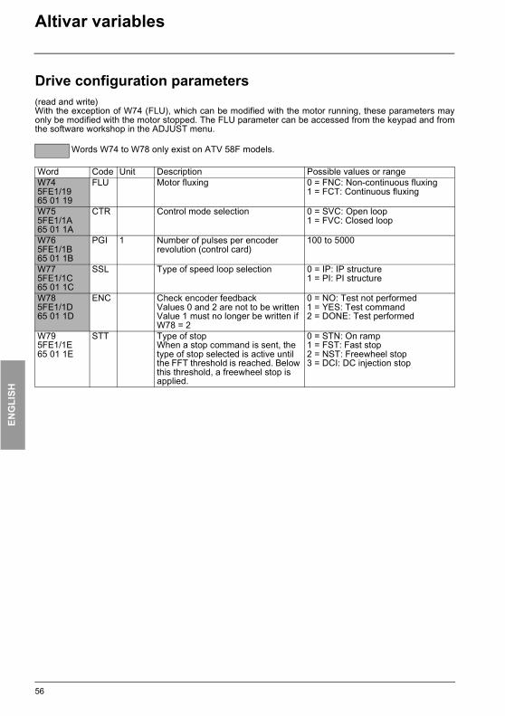
ENG
LISH
ATV38_58.book Page 56 Mardi, 11. février 2003 11:15 11
Altivar variables
Drive configuration parameters(read and write)With the exception of W74 (FLU), which can be modified with the motor running, these parameters mayonly be modified with the motor stopped. The FLU parameter can be accessed from the keypad and fromthe software workshop in the ADJUST menu.
Words W74 to W78 only exist on ATV 58F models.
Word Code Unit Description Possible values or rangeW745FE1/1965 01 19
FLU Motor fluxing 0 = FNC: Non-continuous fluxing1 = FCT: Continuous fluxing
W755FE1/1A65 01 1A
CTR Control mode selection 0 = SVC: Open loop 1 = FVC: Closed loop
W765FE1/1B65 01 1B
PGI 1 Number of pulses per encoder revolution (control card)
100 to 5000
W775FE1/1C65 01 1C
SSL Type of speed loop selection 0 = IP: IP structure1 = PI: PI structure
W785FE1/1D65 01 1D
ENC Check encoder feedback Values 0 and 2 are not to be writtenValue 1 must no longer be written if W78 = 2
0 = NO: Test not performed1 = YES: Test command2 = DONE: Test performed
W795FE1/1E65 01 1E
STT Type of stopWhen a stop command is sent, the type of stop selected is active until the FFT threshold is reached. Below this threshold, a freewheel stop is applied.
0 = STN: On ramp1 = FST: Fast stop2 = NST: Freewheel stop3 = DCI: DC injection stop
56

ENG
LISH
ATV38_58.book Page 57 Mardi, 11. février 2003 11:15 11
Altivar variables
I/O configuration parameters(read and write)These parameters may only be modified with the motor stopped.
Word Code Description Possible values or rangeW1005FE2/166 01 01
LI1 Assignment of logic input "LI1"
1 = STP: Stop (If TCC = 3W)2 = FW: Forward operation (If TCC = 2W)
W1015FE2/266 01 02
LI2 Assignment of logic input "LI2"
0 = NO: Not assigned2 = FW: Forward operation (If TCC = 3W)3 = RV: Reverse operation4 = RP2: Ramp switching5 = JOG: Jog operation6 = + SP: + speed 7 = - SP: - speed 8 = PS2: 2 preset speeds11 = RFC: Reference switching 12 = NST: Freewheel stop13 = DCI: DC injection stop14 = FST: Fast stop15 = CHP: Motor switching or, for ATV 58F only, if CTR = FVC, open loop/closed loop switching16 = TL2: Second torque limit (except ATV 38)17 = FLO: Forced local mode18 = RST: Fault reset19 = ATN: Auto-tuning22 = PAU: PI(D) auto-man24 = PR2: 2 preset PI(D) references26 = TLA: Torque limitation via AI (except ATV 38)27 = EDD: External faultValues specific to ATV 58F:20 = SPM: Save reference21 = FLI: Motor fluxing23 = PIS: Integral shunting PI(D)Value specific to ATV 38:28 = FTK: Forced terminal (terminal mode)
57

ENG
LISH
ATV38_58.book Page 58 Mardi, 11. février 2003 11:15 11
Altivar variables
I/O configuration parameters(read and write)These parameters may only be modified with the motor stopped.
Word Code Description Possible values or rangeW1025FE2/366 01 03
LI3 Assignment of logic input "LI3"
0 = NO: Not assigned3 = RV: Reverse operation4 = RP2: Ramp switching5 = JOG: Jog operation6 = + SP: + speed 7 = - SP: - speed 8 = PS2: 2 preset speeds9 = PS4: 4 preset speeds11 = RFC: Reference switching 12 = NST: Freewheel stop13 = DCI: DC injection stop14 = FST: Fast stop15 = CHP: Motor switching or, for ATV 58F only, if CTR = FVC, open loop/closed loop switching16 = TL2: Second torque limit (except ATV 38)17 = FLO: Forced local mode18 = RST: Fault reset19 = ATN: Auto-tuning22 = PAU: PI(D) auto-man24 = PR2: 2 preset PI(D) references25 = PR4: 4 preset PI(D) references26 = TLA: Torque limitation via AI (except ATV 38)27 = EDD: External faultValues specific to ATV 58F:20 = SPM: Save reference21 = FLI: Motor fluxing23 = PIS: Integral shunting PI(D)Value specific to ATV 38:28 = FTK: Forced terminal (terminal mode)
W1035FE2/466 01 04
LI4 Assignment of logic input "LI4"
Identical to W102
W1045FE2/566 01 05
LI5 Assignment of logic input "LI5"
Identical to W102
W1055FE2/666 01 06
LI6 Assignment of logic input "LI6"
Identical to W102
58
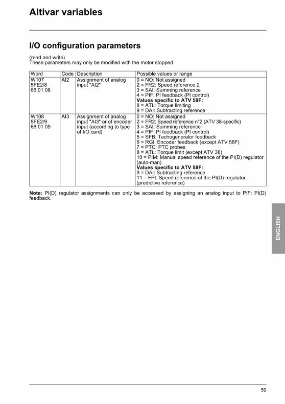
ENG
LISH
ATV38_58.book Page 59 Mardi, 11. février 2003 11:15 11
Altivar variables
I/O configuration parameters(read and write)These parameters may only be modified with the motor stopped.
Note: PI(D) regulator assignments can only be accessed by assigning an analog input to PIF: PI(D)feedback.
Word Code Description Possible values or rangeW1075FE2/866 01 08
AI2 Assignment of analog input "AI2"
0 = NO: Not assigned2 = FR2: Speed reference 23 = SAI: Summing reference4 = PIF: PI feedback (PI control)Values specific to ATV 58F:8 = ATL: Torque limiting9 = DAI: Subtracting reference
W1085FE2/966 01 09
AI3 Assignment of analog input "AI3" or of encoder input (according to type of I/O card)
0 = NO: Not assigned2 = FR2: Speed reference n°2 (ATV 38-specific)3 = SAI: Summing reference4 = PIF: PI feedback (PI control)5 = SFB: Tachogenerator feedback 6 = RGI: Encoder feedback (except ATV 58F)7 = PTC: PTC probes8 = ATL: Torque limit (except ATV 38)10 = PIM: Manual speed reference of the PI(D) regulator (auto-man)Values specific to ATV 58F:9 = DAI: Subtracting reference11 = FPI: Speed reference of the PI(D) regulator (predictive reference)
59

ENG
LISH
ATV38_58.book Page 60 Mardi, 11. février 2003 11:15 11
Altivar variables
I/O configuration parameters(read and write)These parameters may only be modified with the motor stopped.
Word Code Description Possible values or rangeW1105FE2/B66 01 0B
R2 Assignment of relay "R2" 0 = NO: Not assigned2 = RUN: Drive running3 = OCC: Downstream contactor control4 = FTA: Frequency threshold (FTD) reached5 = FLA: High speed reached6 = CTA: Current threshold (CTD) reached7 = SRA: Frequency reference reached8 = TSA: Thermal threshold (TTD) reached9 = BLC: Brake sequence (except ATV 38)12 = APL: Loss of 4-20mA13 = F2A: Second frequency threshold reached (F2D)14 = TAD: Drive thermal state threshold reachedValues specific to ATV 58F:10 = PEE: PI(D) error11 = PFA: PI(D) feedback alarm
W1115FE2/C66 01 0C
LO Assignment of logic output "LO"
Identical to W110
W1125FE2/D66 01 0D
AO Assignment of analog output "AO"
0 = NO: Not assigned1 = OCR: Motor current2 = OFR: Motor speed3 = ORP: Ramp output4 = TRQ: Motor torque (except ATV 38)5 = STQ: Signed motor torque (except ATV 38)6 = ORS: Signed ramp output7 = OPS: PI(D) reference8 = OPF: PI(D) feedback9 = OPE: PI(D) error10 = OPI: PI(D) integral11 = OPR: Motor power12 = THR: Motor thermal state13 = THD: Drive thermal state
W1135FE2/E66 01 0E
AO1 Assignment of analog output "AO1"
Identical to W112
60
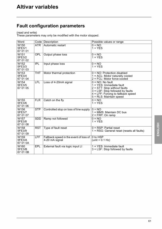
ENG
LISH
ATV38_58.book Page 61 Mardi, 11. février 2003 11:15 11
Altivar variables
Fault configuration parameters(read and write)These parameters may only be modified with the motor stopped.
Word Code Description Possible values or rangeW1505FE3/167 01 01
ATR Automatic restart 0 = NO1 = YES
W1515FE3/267 01 02
OPL Output phase loss 0 = NO1 = YES
W1525FE3/367 01 03
IPL Input phase loss 0 = NO1 = YES
W1535FE3/467 01 04
THT Motor thermal protection 0 = NO: Protection disabled1 = ACL: Motor naturally cooled 2 = FCL: Motor force-cooled
W1545FE3/567 01 05
LFL Loss of 4-20mA signal 0 = NO: No fault 1 = YES: Immediate fault2 = STT: Stop without faults3 = LSF: Stop followed by faults4 = LFF: Forcing to fallback speed5 = RLS: Maintain speed
W1555FE3/667 01 06
FLR Catch on the fly 0 = NO1 = YES
W1565FE3/767 01 07
STP Controlled stop on loss of line supply 0 = NO1 = MMS: Maintain DC bus 2 = FRP: On ramp
W1575FE3/867 01 08
SDD Ramp not followed 0 = NO1 = YES
W1585FE3/967 01 09
RST Type of fault reset 0 = RSP: Partial reset 1 = RSG: General reset (resets all faults)
W1595FE3/A67 01 0A
LFF Fallback speed in the event of loss of 4-20 mA signal
0 to HSP(unit = 0.1 Hz)
W1605FE3/B67 01 0B
EPL External fault via logic input LI 1 = YES: Immediate fault3 = LSF: Stop followed by faults
61

ENG
LISH
ATV38_58.book Page 62 Mardi, 11. février 2003 11:15 11
Altivar variables
Adjustment parameters(read and write)These parameters may be modified with the motor stopped or running.
(1) Parameter does not exist for ATV 58F.
Word Code Unit Description Possible values or rangeW2505FE5/169 01 01
HSP 0.1 Hz High speed LSP to TFR
W2515FE5/269 01 02
LSP 0.1 Hz Low speed 0 to HSP
W2525FE5/369 01 03
ACC 0.1 sor0.01 s
Acceleration (time between 0 and FRS)
ATV 38 and ATV 58:- 0: ramp 0.05 s- 1 to 9999: ramp 0.1 to 999.9 s
ATV 58F only, where INR = 0:- 1 to 9999: ramp 0.1 to 999.9 s(the value 0 does not exist)
ATV 58F only, where INR = 1:- 1 to 9999: ramp 0.01 to 99.99 s(the value 0 does not exist)
W2535FE5/469 01 04
DEC 0.1 sor0.01 s
Deceleration (time between FRS and 0)
W2545FE5/569 01 05
UFR 1% IR compensation(Adjustment of auto-tune value)
0 to 150 if SPC = NO0 to 800 if SPC = YES (except ATV 58F)0 if CFG = VTAlways at 0 for ATV 38
W2555FE5/669 01 06
FLG 1% IP type frequency loop gain 0 to 100
W2565FE5/769 01 07(1)
PFL 1% U/F ratio profile ATV 38: 0 to 100ATV 58: 0 to 100 if CFG = VT100 if CFG = HDG or GEN
W2575FE5/869 01 08
STA 1% IP type frequency loop stability 0 to 100
W2585FE5/969 01 09
ITH 0.1 A Thermal protection current ATV 38: 0.25 INV to 1.1 INVATV 58 and ATV 58F: 0.25 INV to 1.36 INVINV = nominal drive current
W2595FE5/A69 01 0A
SLP 1% Slip compensation 0 if CFG = VT (except ATV 58F)0 to 150 if CFG = HDG or GENAlways at 0 for ATV 38
W2605FE5/B69 01 0B
AC2 0.1 sor0.01 s
Acceleration 2 (time between 0 and FRS)
ATV 38 and ATV 58:- 0: ramp 0.05 s- 1 to 9999: ramp 0.1 to 999.9 s
ATV 58F only, where INR = 0:- 1 to 9999: ramp 0.1 to 999.9 s(the value 0 does not exist)
ATV 58F only, where INR = 1:- 1 to 9999: ramp 0.01 to 99.99 s(the value 0 does not exist)
W2615FE5/C69 01 0C
DE2 0.1 sor0.01 s
Deceleration 2(time between FRS and 0)
62

ENG
LISH
ATV38_58.book Page 63 Mardi, 11. février 2003 11:15 11
Altivar variables
Adjustment parameters(read and write)These parameters may be modified with the motor stopped or running.
Word Code Unit Description Possible values or rangeW2625FE5/D69 01 0D
JOG 0.1 Hz JOG frequency (jog operation) 0 to 100
W2635FE5/E69 01 0E
JGT 0.1 s Anti-repeat delay between 2 jog operations (JOG)
0 to 20
W2645FE5/F69 01 0F
SP2 0.1 Hz Preset speed 2 LSP to HSP
W2655FE5/1069 01 10
SP3 0.1 Hz Preset speed 3 LSP to HSP
W2665FE5/1169 01 11
SP4 0.1 Hz Preset speed 4 LSP to HSP
W2675FE5/1269 01 12
SP5 0.1 Hz Preset speed 5 LSP to HSP
W2685FE5/1369 01 13
SP6 0.1 Hz Preset speed 6 LSP to HSP
W2695FE5/1469 01 14
SP7 0.1 Hz Preset speed 7 LSP to HSP
W2705FE5/1569 01 15
IDC 0.1 A Injection current ATV 38: 0.1 to 1.1 INVATV 58 and ATV 58F: 0.1 to 1.36 INV(INV = nominal drive current)
W2715FE5/1669 01 16
TDC 0.1 s Injection time (in the case of automatic injection on stopping) or, for ATV 58F only, if CTR = FVC, zero speed time on stopping
0 to 300 = from 0.0 s to 30.0 s301 = CONT: continuous action
W2725FE5/1769 01 17
TLS 0.1 s Max. time at low speed (LSP) 0 = NO: no limit1 to 9999 = from 0.1 s to 999.9 s
W2735FE5/1869 01 18
BRL 0.1 Hz Brake release threshold Parameter does not exist for ATV 38 and ATV 58F (ATV 58 only).
0 to 100
W2745FE5/1969 01 19
BEN 0.1 Hz Brake engage threshold (parameter not significant for ATV 58F if CTR = FVC)Parameter not relevant for ATV 38
0 to LSP
W2755FE5/1A69 01 1A
BRT 0.01 s Brake release timeParameter not relevant for ATV 38
0 to 500
W2765FE5/1B69 01 1B
BET 0.01 s Brake engage timeParameter not relevant for ATV 38
0 to 500
W2775FE5/1C69 01 1C
IBR 0.1 A Brake release current thresholdParameter not relevant for ATV 38
0 to 1.36 INV (INV = nominal drive current)
63
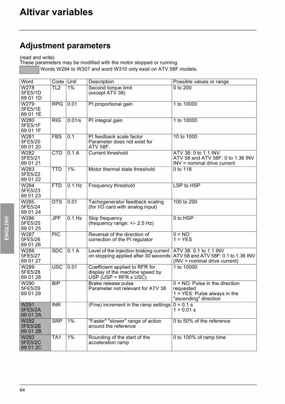
ENG
LISH
ATV38_58.book Page 64 Mardi, 11. février 2003 11:15 11
Altivar variables
Adjustment parameters(read and write)These parameters may be modified with the motor stopped or running.
Words W294 to W307 and word W310 only exist on ATV 58F models.
Word Code Unit Description Possible values or rangeW2785FE5/1D69 01 1D
TL2 1% Second torque limit(except ATV 38)
0 to 200
W2795FE5/1E69 01 1E
RPG 0.01 PI proportional gain 1 to 10000
W2805FE5/1F69 01 1F
RIG 0.01/s PI integral gain 1 to 10000
W2815FE5/2069 01 20
FBS 0.1 PI feedback scale factorParameter does not exist for ATV 58F.
10 to 1000
W2825FE5/2169 01 21
CTD 0.1 A Current threshold ATV 38: 0 to 1.1 INVATV 58 and ATV 58F: 0 to 1.36 INVINV = nominal drive current
W2835FE5/2269 01 22
TTD 1% Motor thermal state threshold 0 to 118
W2845FE5/2369 01 23
FTD 0.1 Hz Frequency threshold LSP to HSP
W2855FE5/2469 01 24
DTS 0.01 Tachogenerator feedback scaling (for I/O card with analog input)
100 to 200
W2865FE5/2569 01 25
JPF 0.1 Hz Skip frequency(frequency range: +/- 2.5 Hz)
0 to HSP
W2875FE5/2669 01 26
PIC Reversal of the direction of correction of the PI regulator
0 = NO1 = YES
W2885FE5/2769 01 27
SDC 0.1 A Level of the injection braking current on stopping applied after 30 seconds
ATV 38: 0.1 to 1.1 INVATV 58 and ATV 58F: 0.1 to 1.36 INV(INV = nominal drive current)
W2895FE5/2869 01 28
USC 0.01 Coefficient applied to RFR for display of the machine speed by USP (USP = RFR x USC)
1 to 10000
W2905FE5/2969 01 29
BIP Brake release pulseParameter not relevant for ATV 38
0 = NO: Pulse in the direction requested1 = YES: Pulse always in the "ascending" direction
W2915FE5/2A69 01 2A
INR (Fine) increment in the ramp settings 0 = 0.1 s1 = 0.01 s
W2925FE5/2B69 01 2B
SRP 1% "Faster" "slower" range of action around the reference
0 to 50% of the reference
W2935FE5/2C69 01 2C
TA1 1% Rounding of the start of the acceleration ramp
0 to 100% of ramp time
64

ENG
LISH
ATV38_58.book Page 65 Mardi, 11. février 2003 11:15 11
Altivar variables
Adjustment parameters(read and write)These parameters may be modified with the motor stopped or running.
Words W294 to W307 and word W310 only exist on ATV 58F models.
Word Code Unit Description Possible values or rangeW2945FE5/2D69 01 2D
TA2 1% Rounding of the end of the acceleration ramp
0 to 100% of ramp time -TA1
W2955FE5/2E69 01 2E
TA3 1% Rounding of the start of the deceleration ramp
0 to 100% of ramp time
W2965FE5/2F69 01 2F
TA4 1% Rounding of the end of the deceleration ramp
0 to 100% of ramp time -TA3
W2975FE5/3069 01 30
SPG 1% PI type speed loop proportional gain 0 to 1000
W2985FE5/3169 01 31
SIG 1% PI type speed loop integral gain 0 to 1000
W2995FE5/3269 01 32
REO PI(D) regulator reference offset -999 to +999
W3005FE5/3369 01 33
PAL 1% PI(D) feedback alarm min. threshold 0 to 100%
W3015FE5/3469 01 34
PAH 1% PI(D) feedback alarm max. threshold 0 to 100%
W3025FE5/3569 01 35
PER 1% "PI(D) error" alarm max. threshold 0 to 100%
W3035FE5/3669 01 36
RDG 0.01 Derivative gain of the PI(D) regulator 0 to 10000
W3045FE5/3769 01 37
PSP 0.1 s PI(D) feedback filter time constant 0 to 100
W3055FE5/3869 01 38
PSR 1% PI(D) speed input multiplier ratio 0 to 100
W3065FE5/3969 01 39
PLR 1% PI(D) regulator deadband ratio 0 to 100
W3075FE5/3A69 01 3A
PLB 0.1Hz PI(D) regulator deadband threshold 0 to HSP
W3085FE5/3B69 01 3B
PI2 1% 2nd preset PI(D) reference 0 to 100
W3095FE5/3C69 01 3C
PI3 1% 3rd preset PI(D) reference 0 to 100
W3105FE5/3D69 01 3D
PRG PI(D) regulator reference gain -999 to +999
65

ENG
LISH
ATV38_58.book Page 66 Mardi, 11. février 2003 11:15 11
Altivar variables
Adjustment parameters(read and write)These parameters may be modified with the motor stopped or running.
Word Code Unit Description Possible values or rangeW3115FE5/3E69 01 3E
JF2 0.1 Hz Second skip frequency (frequency range: +/- 2.5 Hz)
0 to HSP
W3125FE5/3F69 01 3F
JF3 0.1 Hz Third skip frequency (frequency range: +/- 2.5 Hz)
0 to HSP
W3135FE5/4069 01 40
FFT 0.1 Hz Freewheel stop trip threshold 0 to HSP
W3145FE5/4169 01 41
F2D 0.1 Hz Second frequency threshold LSP to HSP
W3155FE5/4269 01 42
DTD % Drive thermal state threshold 0 to 118
W3165FE5/4369 01 43
SP8 0.1 Hz Preset speed 8ATV 38-specific parameter
LSP to HSP
66

ENG
LISH
ATV38_58.book Page 67 Mardi, 11. février 2003 11:15 11
Altivar variables
Control parameters(read and write)
(1) ATV 58F: 0.1Hz or 0.015Hz- If bit 9 of CMI is at 0, the resolution is 0.1Hz (0 to 5000 range for 0 to 500Hz). - If bit 9 of CMI is at 1, the resolution is approximately 0.015Hz (0 to 32767 range for 0 to 500Hz).
Word Code Unit Description Possible values or rangeW4005FE7/16A 01 01
CMD DRIVECOM control register Parameter reinitialized at end of "time-out" unless bit 14 of CMI is set to 1 (W402 or 5FE7/3)
Bit 0: Switch onBit 1: Disable voltageBit 2: Quick stopBit 3: Enable operationBits 4 to 6: Set to 0Bit 7: Fault resetBits 9 to 10: Set to 0Bit 11 = 0: Forward direction commandBit 11 = 1: Reverse direction commandBit 12 = 0: No actionBit 12 = 1: Stop on ramp commandBit 13 = 0: No actionBit 13 = 1: Injection stop commandBit 14 = 0: No actionBit 14 = 1: Fast stop commandBits 8 and 15: LOCAL/LINE mode selection - Bit 15 = 0 and bit 8 = 0: LINE mode Drivecom profile - Bit 15 = 1 and bit 8 = 1: LOCAL mode
W4015FE7/26A 01 02
LFR 0.1Hz(1)
Frequency reference in line mode (signed in two's complement)
LSP to HSP
Parameter reinitialized at end of "time-out" unless bit 14 of CMI is set to 1 (W402 or 5FE7/3)
67

ENG
LISH
ATV38_58.book Page 68 Mardi, 11. février 2003 11:15 11
Altivar variables
Control parameters(read and write)
(1) Caution: The EEPROM life limit is 100,000 write operations.
Word Code Description Possible values or rangeW4025FE7/36A 01 03
CMI Extended control registerParameter reinitialized at end of "time-out" unless bit 14 of CMI is set to 1
Bit 0 = 0: No actionBit 0 = 1: Recall factory settings command. This bit automatically resets to 0 after accepting the request, but if CMI is a periodic variable, the PLC program must write it to 0 after the first request has been accepted. Inactive if the motor is powered up.Bit 1 = 0: No actionBit 1 = 1: Save configuration/adjustments in EEPROM if voltage is sufficient (no USF fault). This bit automatically resets to 0 after accepting the request, but if CMI is a periodic variable, the PLC program must write it to 0 after the first request has been accepted (1).Bit 2 = 0: No actionBit 2 = 1: Recall configuration/settings from EEPROM. It is inactive if the motor is powered up. This bit automatically resets to 0 after accepting the request, but if CMI is a periodic variable, the PLC program must write it to 0 after the first request has been accepted.Bit 3 = 0: No actionBit 3 = 1: External fault command (EPF)Bit 4 = 0: No actionBit 4 = 1: Ramp switching commandBit 5 = 0: No actionBit 5 = 1: Motor switching command or, for ATV 58F only, if CTR = FVC, open loop/closed loop switchingBit 6 = 0: No actionBit 6 = 1: For controlling the second torque limit (except ATV 38)Bit 7: Always leave this bit at 0Bit 8 = 0: No actionBit 8 = 1: For ATV 58F only, short-circuiting of the rampBit 9 = 0: The LFR reference (W401 or 16#5FE7/2) is expressed with a resolution of 0.1HzBit 9 = 1: The LFR reference is expressed with a resolution of 0.015HzBits 10 to 12: ReservedBit 13 = 0: Drive not locked when stoppedBit 13 = 1: Drive locked when stoppedBit 14 (NTO) = 0: Control with communication checkBit 14 (NTO) = 1: Control with no communication check
Use restricted to the debug phase for safety reasons.
Bit 15 = 0: Parameter consistency checkBit 15 = 1: No parameter consistency check: drive locked when stopped. Switching this bit to 0 will revalidate all parameters.
68
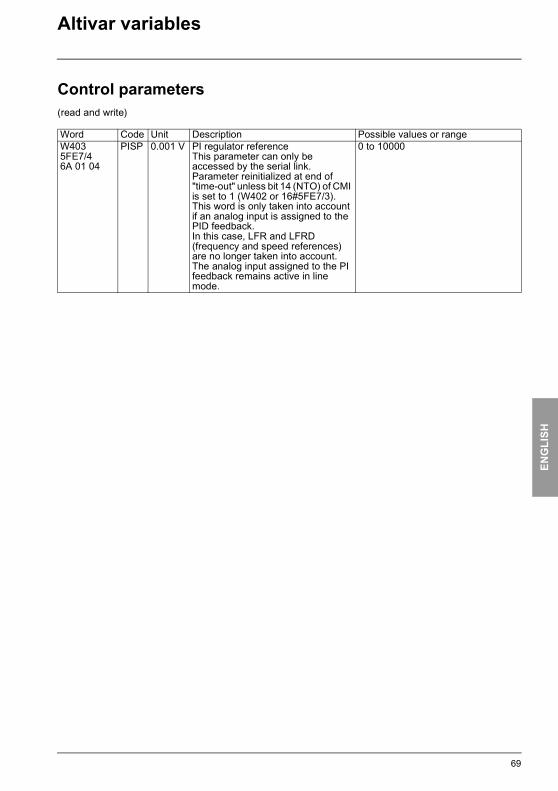
ENG
LISH
ATV38_58.book Page 69 Mardi, 11. février 2003 11:15 11
Altivar variables
Control parameters(read and write)
Word Code Unit Description Possible values or rangeW4035FE7/46A 01 04
PISP 0.001 V PI regulator referenceThis parameter can only be accessed by the serial link.Parameter reinitialized at end of "time-out" unless bit 14 (NTO) of CMI is set to 1 (W402 or 16#5FE7/3).This word is only taken into account if an analog input is assigned to the PID feedback.In this case, LFR and LFRD (frequency and speed references) are no longer taken into account. The analog input assigned to the PI feedback remains active in line mode.
0 to 10000
69
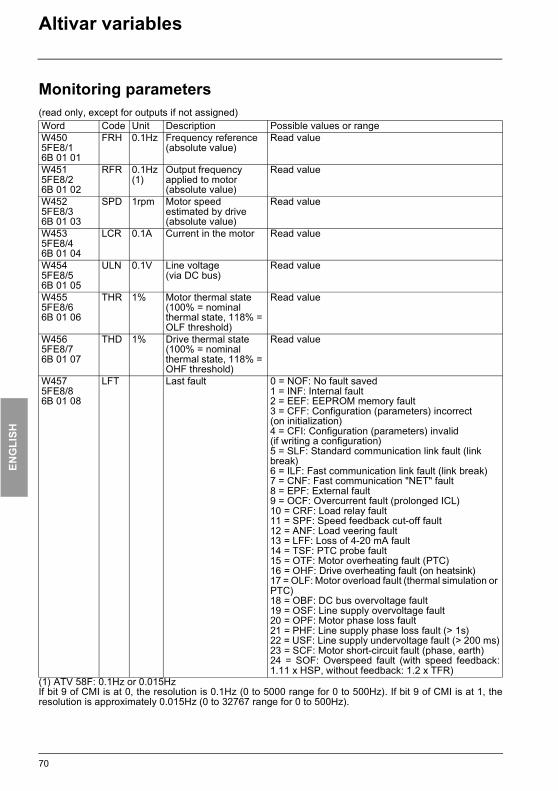
ENG
LISH
ATV38_58.book Page 70 Mardi, 11. février 2003 11:15 11
Altivar variables
Monitoring parameters(read only, except for outputs if not assigned)
(1) ATV 58F: 0.1Hz or 0.015HzIf bit 9 of CMI is at 0, the resolution is 0.1Hz (0 to 5000 range for 0 to 500Hz). If bit 9 of CMI is at 1, theresolution is approximately 0.015Hz (0 to 32767 range for 0 to 500Hz).
Word Code Unit Description Possible values or rangeW4505FE8/16B 01 01
FRH 0.1Hz Frequency reference (absolute value)
Read value
W4515FE8/26B 01 02
RFR 0.1Hz(1)
Output frequency applied to motor (absolute value)
Read value
W4525FE8/36B 01 03
SPD 1rpm Motor speed estimated by drive (absolute value)
Read value
W4535FE8/46B 01 04
LCR 0.1A Current in the motor Read value
W4545FE8/56B 01 05
ULN 0.1V Line voltage(via DC bus)
Read value
W4555FE8/66B 01 06
THR 1% Motor thermal state (100% = nominal thermal state, 118% = OLF threshold)
Read value
W4565FE8/76B 01 07
THD 1% Drive thermal state (100% = nominal thermal state, 118% = OHF threshold)
Read value
W4575FE8/86B 01 08
LFT Last fault 0 = NOF: No fault saved1 = INF: Internal fault2 = EEF: EEPROM memory fault3 = CFF: Configuration (parameters) incorrect(on initialization)4 = CFI: Configuration (parameters) invalid(if writing a configuration)5 = SLF: Standard communication link fault (link break)6 = ILF: Fast communication link fault (link break)7 = CNF: Fast communication "NET" fault8 = EPF: External fault9 = OCF: Overcurrent fault (prolonged ICL)10 = CRF: Load relay fault11 = SPF: Speed feedback cut-off fault12 = ANF: Load veering fault13 = LFF: Loss of 4-20 mA fault14 = TSF: PTC probe fault15 = OTF: Motor overheating fault (PTC)16 = OHF: Drive overheating fault (on heatsink)17 = OLF: Motor overload fault (thermal simulation or PTC)18 = OBF: DC bus overvoltage fault19 = OSF: Line supply overvoltage fault20 = OPF: Motor phase loss fault21 = PHF: Line supply phase loss fault (> 1s)22 = USF: Line supply undervoltage fault (> 200 ms)23 = SCF: Motor short-circuit fault (phase, earth)24 = SOF: Overspeed fault (with speed feedback:1.11 x HSP, without feedback: 1.2 x TFR)
70

ENG
LISH
ATV38_58.book Page 71 Mardi, 11. février 2003 11:15 11
Altivar variables
Monitoring parameters(read only, except for outputs if not assigned)
Word Code Description Possible values or rangeW4585FE8/96B 01 09
ETA DRIVECOM status register
Bit 0: Ready to switch onBit 1: Switched onBit 2: Operation enabledBit 3 = 0: Fault absentBit 3 = 1: Malfunction, fault present (FAI)Bit 4: Voltage disabledBit 5: Quick stopBit 6: Switch on disabledBit 7 = 0: Alarm absentBit 7 = 1: Alarm presentBit 8: ReservedBit 9 = 0: Forced local mode in progress (FLO)Bit 9 = 1: Forced local mode absentBit 10 = 0: Reference not reached (transient state)Bit 10 = 1: Reference reached (steady state)Bit 11 = 0: LFRD reference normalBit 11 = 1: LFRD reference exceeded (< LSP or > HSP) Caution: LFRD is expressed in rpm, LSP and HSP in HzBits 12 and 13: ReservedBit 14 = 0: No stop from keypad STOP key Bit 14 = 1: Stop from keypad STOP key Bit 15 = 0: Forward rotation (output frequency)Bit 15 = 1: Reverse rotation (output frequency)
71
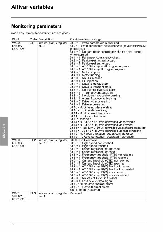
ENG
LISH
ATV38_58.book Page 72 Mardi, 11. février 2003 11:15 11
Altivar variables
Monitoring parameters(read only, except for outputs if not assigned)
Word Code Description Possible values or rangeW4595FE8/A6B 01 0A
ETI Internal status register no. 1
Bit 0 = 0: Write parameters authorizedBit 0 = 1: Write parameters not authorized (save in EEPROM in progress)Bit 1 = 0: No parameter consistency check: drive locked when stoppedBit 1 = 1: Parameter consistency checkBit 2 = 0: Fault reset not authorizedBit 2 = 1: Fault reset authorizedBit 3 = 0: ATV 58F only, no fluxing in progressBit 3 = 1: ATV 58F only, fluxing in progressBit 4 = 0: Motor stoppedBit 4 = 1: Motor runningBit 5 = 0: No DC injection Bit 5 = 1: DC injection Bit 6 = 0: Drive in steady stateBit 6 = 1: Drive in transient stateBit 7 = 0: No thermal overload alarmBit 7 = 1: Thermal overload alarmBit 8 = 0: No alarm if excessive brakingBit 8 = 1: Alarm if excessive brakingBit 9 = 0: Drive not acceleratingBit 9 = 1: Drive acceleratingBit 10 = 0: Drive not deceleratingBit 10 = 1: Drive deceleratingBit 11 = 0: No current limit alarmBit 11 = 1: Current limit alarmBit 12: ReservedBit 14 = 0, Bit 13 = 0: Drive controlled via terminalsBit 14 = 0, Bit 13 = 1: Drive controlled via keypad Bit 14 = 1, Bit 13 = 0: Drive controlled via standard serial linkBit 14 = 1, Bit 13 = 1: Drive controlled via fast serial linkBit 15 = 0: Forward rotation requested (reference)Bit 15 = 1: Reverse rotation requested (reference)
W4605FE8/B6B 01 0B
ETI2 Internal status register no. 2
Bits 0 to 2: ReservedBit 3 = 0: High speed not reachedBit 3 = 1: High speed reachedBit 4 = 0: Speed reference not reachedBit 4 = 1: Speed reference reachedBit 5 = 0: Frequency threshold (FTD) not reachedBit 5 = 1: Frequency threshold (FTD) reachedBit 6 = 0: Current threshold (CTD) not reachedBit 6 = 1: Current threshold (CTD) reachedBit 7 = 0: ATV 58F only, PI(D) feedback correctBit 7 = 1: ATV 58F only, PI(D) feedback exceededBit 8 = 0: ATV 58F only, PI(D) error correctBit 8 = 1: ATV 58F only, PI(D) error exceededBit 9 = 0: No loss of 4 - 20 mA signalBit 9 = 1: Loss of 4 - 20mA signalBit 10 = 0: No drive thermal alarmBit 10 = 1: Drive thermal alarmBits 11 to 15: Reserved
W4615FE8/C6B 01 0C
ETI3 Internal status register no. 3
Reserved
72

ENG
LISH
ATV38_58.book Page 73 Mardi, 11. février 2003 11:15 11
Altivar variables
Monitoring parameters(read only, except for outputs if not assigned)
Word Code Description Possible values or rangeW4625FE8/D6B 01 0D
DP1 Past fault no. 1 Same format as LFT (W457 or 16#5FE8/8)
W4635FE8/E6B 01 0E
EP1 Status during past fault no. 1
Bit 0 same as ETA bit 1:Bit 0 = 0: Drive not readyBit 0 = 1: Drive ready (RDY)Bit 1 same as ETA bit 5:Bit 1 = 0: Emergency stop in progressBit 1 = 1: Emergency stop absentBit 2 same as ETA bit 6:Bit 2 = 0: State ≠ Switch on disabled)Bit 2 = 1: State = Switch on disabled (ATV locked, freewheel
stop)Bit 3 same as ETA bit 9: Bit 3 = 0: Forced local mode in progress (FLO)Bit 3 = 1: Forced local mode absentBit 4 same as ETA bit 15: Bit 4 = 0: Forward rotation (output frequency)Bit 4 = 1: Reverse rotation (output frequency)Bit 5 same as ETI bit 4:Bit 5 = 0: Motor stoppedBit 5 = 1: Motor runningBit 6 same as ETI bit 5: Bit 6 = 0: No DC injection Bit 6 = 1: DC injection Bit 7 same as ETI bit 7: Bit 7 = 0: No thermal overload alarmBit 7 = 1: Thermal overload alarmBit 8 same as ETI bit 8:Bit 8 = 0: No alarm if excessive brakingBit 8 = 1: Alarm if excessive brakingBit 9 same as ETI bit 9: Bit 9 = 0: Drive not acceleratingBit 9 = 1: Drive acceleratingBit 10 same as ETI bit 10: Bit 10 = 0: Drive not deceleratingBit 10 = 1: Drive deceleratingBit 11 same as ETI bit 11: Bit 11 = 0: No current limit alarmBit 11 = 1: Current limit alarmBit 12: ReservedBits 13 and 14 same as ETI bits 13 and 14: Bit 14 = 0, Bit 13 = 0: Drive controlled via terminalsBit 14 = 0, Bit 13 = 1: Drive controlled via keypad Bit 14 = 1, Bit 13 = 0: Drive controlled via standard serial linkBit 14 = 1, Bit 13 = 1: Drive controlled via fast serial linkBit 15 same as ETI bit 15:Bit 15 = 0: Forward rotation requested (reference)Bit 15 = 1: Reverse rotation requested (reference)
73

ENG
LISH
ATV38_58.book Page 74 Mardi, 11. février 2003 11:15 11
Altivar variables
Monitoring parameters(read only, except for outputs if not assigned)
Word Code Description Possible values or rangeW4645FE8/F6B 01 0F
DP2 Past fault no. 2 Same format as LFT (W457 or 16#5FE8/8)
W4655FE8/106B 01 10
EP2 Status during past fault no. 2 Same format as EP1 (W463 or 16#5FE8/E)
W4665FE8/116B 01 11
DP3 Past fault no. 3 Same format as LFT (W457 or 16#5FE8/8)
W4675FE8/126B 01 12
EP3 Status during past fault no. 3 Same format as EP1 (W463 or 16#5FE8/E)
W4685FE8/136B 01 13
DP4 Past fault no. 4 Same format as LFT (W457 or 16#5FE8/8)
W4695FE8/146B 01 14
EP4 Status during past fault no. 4 Same format as EP1 (W463 or 16#5FE8/E)
W4705FE8/156B 01 15
DP5 Past fault no. 5 Same format as LFT (W457 or 16#5FE8/8)
W4715FE8/166B 01 16
EP5 Status during past fault no. 5 Same format as EP1 (W463 or 16#5FE8/E)
W4725FE8/176B 01 17
DP6 Past fault no. 6 Same format as LFT (W457 or 16#5FE8/8)
W4735FE8/186B 01 18
EP6 Status during past fault no. 6 Same format as EP1 (W463 or 16#5FE8/E)
W4745FE8/196B 01 19
DP7 Past fault no. 7 Same format as LFT (W457 or 16#5FE8/8)
W4755FE8/1A6B 01 1A
EP7 Status during past fault no. 7 Same format as EP1 (W463 or 16#5FE8/E)
W4765FE8/1B6B 01 1B
DP8 Past fault no. 8 Same format as LFT (W457 or 16#5FE8/8)
W4775FE8/1C6B 01 1C
EP8 Status during past fault no. 8 Same format as EP1 (W463 or 16#5FE8/E)
74

ENG
LISH
ATV38_58.book Page 75 Mardi, 11. février 2003 11:15 11
Altivar variables
Monitoring parameters(read only, except for outputs if not assigned)
Word Code Unit Description Possible values or rangeW4785FE8/1D6B 01 1D
IOLR Image of logic I/O Bit 0 = Image of logic input "LI1" (active at 1)Bit 1 = Image of logic input "LI2" (active at 1)Bit 2 = Image of logic input "LI3" (active at 1)Bit 3 = Image of logic input "LI4" (active at 1)Bit 4 = Image of logic input "LI5" (active at 1)Bit 5 = Image of logic input "LI6" (active at 1)Bits 6 and 7: ReservedBit 8 = Image of relay "R1" (active at 1)Bit 9 = Image of relay "R2" (active at 1)Write authorized if R2 = "NO" (not assigned), except with Interbus-S.Bit 10 = Image of logic output "LO" (active at 1)Write authorized if LO = "NO" (not assigned), except with Interbus-S.Bit 11 = Image of red LED (active at 1)Bit 12 = Image of load relay (active at 1)Bit 13 = Image of dynamic brake transistor (active at 1)Bits 14 and 15: Reserved
W4795FE8/1E6B 01 1E
AI1R 0.001V Image of analog input "AI1" (actual size calibrated and scaled)
Read value
W4805FE8/1F6B 01 1F
AI2R 0.002 mA
Image of analog input "AI2" (actual size calibrated and scaled)
Read value
W4815FE8/206B 01 20
AI3R 0.001Vor 1
Voltage of analog input "AI3" or number of pulses on encoder input, according to type of I/O card
- 10000 to + 10000 (VW3A58201 card)or- 32768 to + 32767 (VW3A58202 card)
W4825FE8/216B 01 21
AOR 0.002 mA
Image of analog output AO
Write authorized if AO = "NO" (not assigned): 0 to 10000Read only if assigned: Read value
75

ENG
LISH
ATV38_58.book Page 76 Mardi, 11. février 2003 11:15 11
Altivar variables
Monitoring parameters(read only, except for outputs if not assigned)
Word W493 only exists on ATV 58F models
Word Code Unit Description Possible values or rangeW4865FE8/256B 01 25
CUS I/O reassigned(macro-config. = CUS)
0 = NO1 = YES
W4875FE8/266B 01 26
OTR 1% Motor torque(except ATV 38)
Read value100% = nominal motor torque
W4885FE8/276B 01 27
FRO 0.1Hz Ramp output (signed)
Read value
W4915FE8/2A6B 01 2A
OPR 1% Output power Read value100% = nominal motor power
W4925FE8/2B6B 01 2B
AO1R
0.002 mA
Image of analog output "AO1"
Write authorized if AO1 = "NO"(not assigned): 0 to 10000Read only if assigned = read value
W4935FE8/2C6B 01 2C
UOP 0.1 V Voltage applied to the motor
Read value
W4945FE8/2D6B 01 2D
APH 1 kWhor1 MWh
Energy consumed If bit 15 = 0, consumption in kWh on bits 0 to 14If bit 15 = 1, consumption in MWh on bits 0 to 14
W4955FE8/2E6B 01 2E
RTH 1 h Operating time in hours (motor powered up)
Read value
76

ENG
LISH
ATV38_58.book Page 77 Mardi, 11. février 2003 11:15 11
Altivar variables
"DRIVECOM" parameters
Word Code Unit Description Possible values or rangeW600603F6D 01 01
ERRD "Malfunction Code"Fault code
Read/Write
16#0 = NOF: No fault 16#1000 = CRF: Load relay faultor = OLF: Motor overload (calculation or PTC probes)or = SOF: Overspeed16#2310 = OCF: Overcurrent (prolonged ICL)16#2320 = SCF: Motor short-circuit (phase/earth)16#3110 = OSF: Line supply overvoltage16#3120 = USF: Line supply undervoltage (> 200 ms)16#3130 = PHF: Line supply phase loss (> 1s)16#3310 = OBF: DC bus overvoltageor = OPF: Output phase loss16#4210 = OHF: Drive overheating16#4310 = OTF: Motor overheating (PTC probes)16#5520 = EEF: EEPROM memory fault16#6100 = INF: Internal fault16#6300 = CFF: Configuration incorrect (on initialization)or = CFI: Configuration invalid (if writing a configuration)16#7300 = ANF: Load veeringor = LFF: Loss of 4-20mA signalor = TSF: PTC probes fault16#7310 = SPF: Speed feedback cut-off 16#7510 = SLF: Serial link fault (cut-off)16#7520 = ILF: Fast serial link fault (cut-off)or = CNF: Fast serial link communication fault 16#8130 = Communication error (CANopen only)16#9000 = EPF: External fault
W60160406D 01 02
CMDD "Control Word"DRIVECOM control register(Same as parameter "CMD")
Read/Write
Parameter reinitialized at end of "time-out" unless bit 14 of CMI is set to 1 (W402 or 5FE7/3)
Bit 0: Switch onBit 1: Disable voltageBit 2: Quick stopBit 3: Enable operationBits 4 to 6: Set to 0Bit 7: Fault resetBits 8 to 10: Set to 0Bit 11 = 0: Forward direction commandBit 11 = 1: Reverse direction commandBit 12 = 0: No actionBit 12 = 1: Stop on ramp commandBit 13 = 0: No actionBit 13 = 1: Injection stop commandBit 14 = 0: No actionBit 14 = 1: Fast stop commandBit 15: Set to 0
77
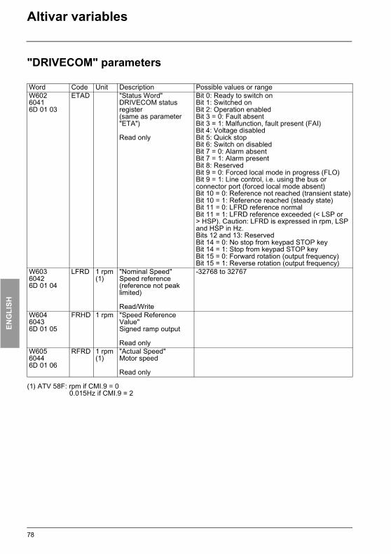
ENG
LISH
ATV38_58.book Page 78 Mardi, 11. février 2003 11:15 11
Altivar variables
"DRIVECOM" parameters
(1) ATV 58F: rpm if CMI.9 = 00.015Hz if CMI.9 = 2
Word Code Unit Description Possible values or rangeW60260416D 01 03
ETAD "Status Word"DRIVECOM status register(same as parameter "ETA")
Read only
Bit 0: Ready to switch onBit 1: Switched onBit 2: Operation enabledBit 3 = 0: Fault absentBit 3 = 1: Malfunction, fault present (FAI)Bit 4: Voltage disabledBit 5: Quick stopBit 6: Switch on disabledBit 7 = 0: Alarm absentBit 7 = 1: Alarm presentBit 8: ReservedBit 9 = 0: Forced local mode in progress (FLO)Bit 9 = 1: Line control, i.e. using the bus or connector port (forced local mode absent)Bit 10 = 0: Reference not reached (transient state)Bit 10 = 1: Reference reached (steady state)Bit 11 = 0: LFRD reference normalBit 11 = 1: LFRD reference exceeded (< LSP or > HSP). Caution: LFRD is expressed in rpm, LSP and HSP in Hz.Bits 12 and 13: ReservedBit 14 = 0: No stop from keypad STOP key Bit 14 = 1: Stop from keypad STOP key Bit 15 = 0: Forward rotation (output frequency)Bit 15 = 1: Reverse rotation (output frequency)
W60360426D 01 04
LFRD 1 rpm(1)
"Nominal Speed"Speed reference(reference not peak limited)
Read/Write
-32768 to 32767
W60460436D 01 05
FRHD 1 rpm "Speed Reference Value"Signed ramp output
Read onlyW60560446D 01 06
RFRD 1 rpm(1)
"Actual Speed"Motor speed
Read only
78

ENG
LISH
ATV38_58.book Page 79 Mardi, 11. février 2003 11:15 11
Altivar variables
"DRIVECOM" parameters
Word Code Unit Description Possible values or rangeW6066046/16D 01 07
SMIL 1 rpm "Speed Min Max Amount"Low speed, equivalent to LSP (W251), but in rpm
Read/Write
0 to HSP in rpm
W6076D 01 08
SMIH Reserved 0
W6086046/26D 01 09
SMAL 1 rpm "Speed Min Max Amount"High speed, equivalent to HSP (W250), but in rpm
Read/Write
LSP to TFR
W6096D 01 0A
SMAH Reserved 0
W6106048/16D 01 0B
SPAL 1 rpm "Speed Acceleration"Speed for calculation of acceleration ramp
Read/Write
1 to 65535
W6116D 01 0C
SPAH Reserved 0
W6126048/26D 01 0D
SPAT 1 s "Speed Acceleration"Time for calculation of acceleration ramp: Time required to go from 0 to SPAL (W610)
Read/Write
0 to 65535
W6136049/16D 01 0E
SPDL 1 rpm "Speed Deceleration"Speed for calculation of deceleration ramp
Read/Write
1 to 65535
W6146D 01 0F
SPDH Reserved 0
W6156049/26D 01 10
SPDT 1 s "Speed Deceleration"Time for calculation of deceleration ramp: Time required to go from SPDL (W613) to 0
Read/Write
0 to 65535
79
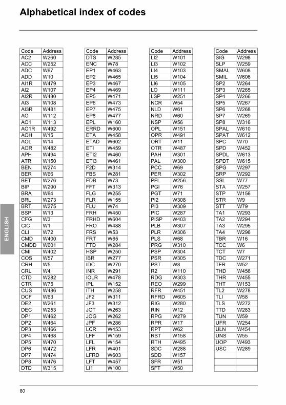
ENG
LISH
ATV38_58.book Page 80 Mardi, 11. février 2003 11:15 11
Alphabetical index of codes
Code Address Code Address Code Address Code AddressAC2 W260 DTS W285 LI2 W101 SIG W298ACC W252 ENC W78 LI3 W102 SLP W259ADC W67 EP1 W463 LI4 W103 SMAL W608ADD W10 EP2 W465 LI5 W104 SMIL W606AI1R W479 EP3 W467 LI6 W105 SP2 W264AI2 W107 EP4 W469 LO W111 SP3 W265AI2R W480 EP5 W471 LSP W251 SP4 W266AI3 W108 EP6 W473 NCR W54 SP5 W267AI3R W481 EP7 W475 NLD W61 SP6 W268AO W112 EP8 W477 NRD W60 SP7 W269AO1 W113 EPL W160 NSP W56 SP8 W316AO1R W492 ERRD W600 OPL W151 SPAL W610AOH W15 ETA W458 OPR W491 SPAT W612AOL W14 ETAD W602 ORT W11 SPC W70AOR W482 ETI W459 OTR W487 SPD W452APH W494 ETI2 W460 PAH W301 SPDL W613ATR W150 ETI3 W461 PAL W300 SPDT W615BEN W274 F2D W314 PCC W69 SPG W297BER W66 FBS W281 PER W302 SRP W292BET W276 FDB W73 PFL W256 SSL W77BIP W290 FFT W313 PGI W76 STA W257BRA W64 FLG W255 PGT W71 STP W156BRL W273 FLR W155 PI2 W308 STR W9BRT W275 FLU W74 PI3 W309 STT W79BSP W13 FRH W450 PIC W287 TA1 W293CFG W3 FRHD W604 PISP W403 TA2 W294CIC W1 FRO W488 PLB W307 TA3 W295CLI W72 FRS W53 PLR W306 TA4 W296CMD W400 FRT W65 PLS W68 TBR W16CMDD W601 FTD W284 PRG W310 TCC W6CMI W402 HSP W250 PSP W304 TCT W7COS W57 IBR W277 PSR W305 TDC W271CRH W5 IDC W270 PST W8 TFR W52CRL W4 INR W291 R2 W110 THD W456CTD W282 IOLR W478 RDG W303 THR W455CTR W75 IPL W152 REO W299 THT W153CUS W486 ITH W258 RFR W451 TL2 W278DCF W63 JF2 W311 RFRD W605 TLI W58DE2 W261 JF3 W312 RIG W280 TLS W272DEC W253 JGT W263 RIN W12 TTD W283DP1 W462 JOG W262 RPG W279 TUN W59DP2 W464 JPF W286 RPR W17 UFR W254DP3 W466 LCR W453 RPT W62 ULN W454DP4 W468 LFF W159 RST W158 UNS W55DP5 W470 LFL W154 RTH W495 UOP W493DP6 W472 LFR W401 SDC W288 USC W289DP7 W474 LFRD W603 SDD W157DP8 W476 LFT W457 SFR W51DTD W315 LI1 W100 SFT W50
80

ATV38_58.book Page 1 Mardi, 11. février 2003 11:15 11
VVDED397058
85598
W9 1493691 01 14 A06
2003-02


![[XLS]iara.wvu.edu · Web view1 11 2 11 3 12 4 11 5 11 6 11 9 11 10 11 11 11 21 11 22 11 23 11 24 11 25 11 26 11 27 11 28 11 30 12 40 11 50 11 51 11 52 11 53 11 61 11 62 11 63 11 90](https://img.pdfslide.us/doc/110x75/5b1a62177f8b9a41258d8f49/xlsiarawvuedu-web-view1-11-2-11-3-12-4-11-5-11-6-11-9-11-10-11-11-11-21.jpg)