Embed Size (px)
Citation preview

1
A FULL SCOPE SIM
ULATOR FOR THE
ARGENTINIAN NUCLEAR PLANT:
ATUCHA II

PRESENTATION CONTENT
Background
AtuchaII plant description
Sim
ulator project scope
Modeling
2
Modeling
HMI
C&I
Difficulties and Challenges
Project present situation

BACKGROUND
At present, two nuclear units are operating in Argentina:
AtuchaI (PHWR-350 Mwe) and Embalse(Candu648 Mwe).
A new unit: ATUCHA II (PHWR-745 Mwe) is due to enter in
3
operation shortly (Expected in September 2011)
ATUCHA II project began in 1980 and was resumed in 2007.
The plant site is located 115 Km. from Buenos Aires.

ATUCHA II PLANT DESCRIPTION
ATUCHA II (pressurized heavy water reactor) utilizes heavy
water as coolant and m
oderator (independent systems). It’s
design was originally based on the MZFR Siemens prototype.
The plant is cooled by the Parana river.
4
It uses natural uranium as fuel. Exhausted fuel is replaced in
parallel with the plant in operation.
A containment building houses the nuclear systems including
a large dim
ension reactor vessel and two steam generators.

ATUCHA II PLANT DESCRIPTION
REACTOR COOLANT
SYSTEM
5
ATUCHA II PLANT DESCRIPTION
MODERATOR COOLING
SYSTEM
6

CONTAINMENT AND
REFUELLING
MACHINE
ATUCHA II PLANT DESCRIPTION
ATUCHA II PLANT DESCRIPTION
7

�Sim
ulator with an
identical layout to
actual control room.
�Sim
ulated control
room will occupy
275 m
Cand 80
Panels.
CONTROL ROOM
LAYOUT
ATUCHA II PLANT DESCRIPTION
ATUCHA II PLANT DESCRIPTION
SAFETY RELATED SYSTEM
CORE INSTRUMENTATION
BOP AUXILARY
8
�19,400 I/O signals
for conventional
instruments
�11,400 Digital +
2,560 Analog Signals
for the Supervision
computer.
�3,400 Additional
signals for the SPPA-
T2000 system.
CORE INSTRUMENTATION
MAIN CONSOLE
REFUELLING MACHINE
HVAC
PRIMARY AUXILARY
BOP AUXILARY

PROJECT SCOPE
Supply of a full scope control room replica sim
ulator. Physical
and functional fidelity requirements will meet ANSI-ANS 3.5.
Supply of a Control room trainer based on virtual panels,
9
process schematics and OM-690 displays.
Training m
aterial for AtuchaII operation staff qualification.
Sim
ulator training scenarios design.
Support for the sim
ulator certification.

Intended dual use: Training and Engineering
I&C approach: SPPA-T2000 & OM690 (TXP System), TXS
and Plant supervision computer will be sim
ulated.
All m
odels will be based on first principle equations and
SIM
ULATOR MAJOR FEATURES
10
All m
odels will be based on first principle equations and
conservation laws.
Extended use of TRAC-RT six equations therm
alhydraulic
code to all the systems with two phase flow phenomena.

�Project start: February 2010 (project month
0)
�Class room trainer RfT
(Phase 1: limited scope): M
ay 2011 (month
15)
�Panels erected at Tecnatom: March 2012 (month
26)
PROJECT W
ORKPLAN
11
�Factory acceptance test beginning:May 2012 (month
28)
�FAT tests completion: Octo
ber 2012 (month
32)
�Full scope replica simulator and class room trainer Ready for Training:
February 2013 (month
36)

ATUCHA II SIM
ULATION TECHNOLOGY
MODELLING
TOOLS
BOP + AUXILIARIES
TEAM SUITE MODEL
SIMULATION
ENVIROMENT
SIMULATION
TECHNOLOGY
INSTRUCTOR
STATION
INSTRUCTOR
STATION
MODELLING
TOOLS
NSSS CODES
INPUT -OUTPUT
CLASS ROOM
TRAINER -HMI
TEAM SKETCH
TEAM SUITE MODEL
BUILDER
HYDRAULIC
NETWORKS
THERMALHYDRAULIC
CONFIGURATION MANAGEMENT SYSTEM
NSSS CODES
INPUT -OUTPUT
ELECTRICAL
NETWORKS
CONVENTIONAL
MODELS
LOGIC & CONTROL
NEUTRONIC

TRAC_RT BASED MODELS
13
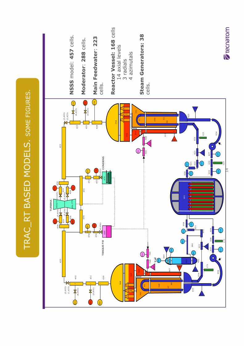
TRAC_RT BASED MODELS. SOME FIGURES.
433
423
364
480
482
430
489
TURBINA
CONDENS.
354
485
479
TANQUE FW
487
481
431
432
470
472
420
471
421
422
475
486476
483
484
474
473
426
425
435
436
424
434
477
452
453
456
454
450
451
488
478
112
2 1 3
11
112
12 2 1
1 2
1 2
(3,422)
(1,423)
(3,421)
(4,422)
(3,425)
c
(3,426)
(3,435)
(3,436)
(4,456)
(2,453)
(3,432)
(1,433)
(4,432)
(3,431)
NSSSmodel: 457cells.
Moderato
r: 288cells.
Main Feedwate
r: 223
cells.
Reacto
r V
essel: 168 cells
14 axial levels
3 radials
14
929
999
62
561
365
361
TAP
939
083
084
085
985
034
081981
983
023
037
032
033
038
035
036
039
930
933
920
922
020
022
024
030
025
028
029
026
027
923
031
931
921
021
082
984
61 60
360
366
367
540
541
362
363
52
351
51
50350
356
357
501
500
521
352
353
355
520
560
123
123
173
173
982
369
359
001
003
937
927
1
1
11
1
3
21
1
1
1
11
13
21
1
6
1
11
1
6
13
925
935
3 radials
4 azimutals
Ste
am G
enerato
rs: 38
cells.

INTEGRATED IN THE SIEMENS SPPA-T2000 OM690 SYSTEM
•SUPERVISION COMPUTER W
ILL BE SIM
ULATED
•FUNCTIONAL CAPABILITIES TO BE INCLUDED IN THE
SIM
ULATOR SCOPE:
•Alarm
sequence displays –
ASD
•Curve displays X-T
•Bar Charts
•Process displays
•Data archive (4 hours)
•Logs
PLANT SUPERVISION COMPUTER
15

ATUCHA II has presently 22 plant systems operated and controlled by the SPPA-
T2000 system. OM690 HMI (70 displays) will be simulated.
SPPA-T200O: PLANT SYSTEMS
16
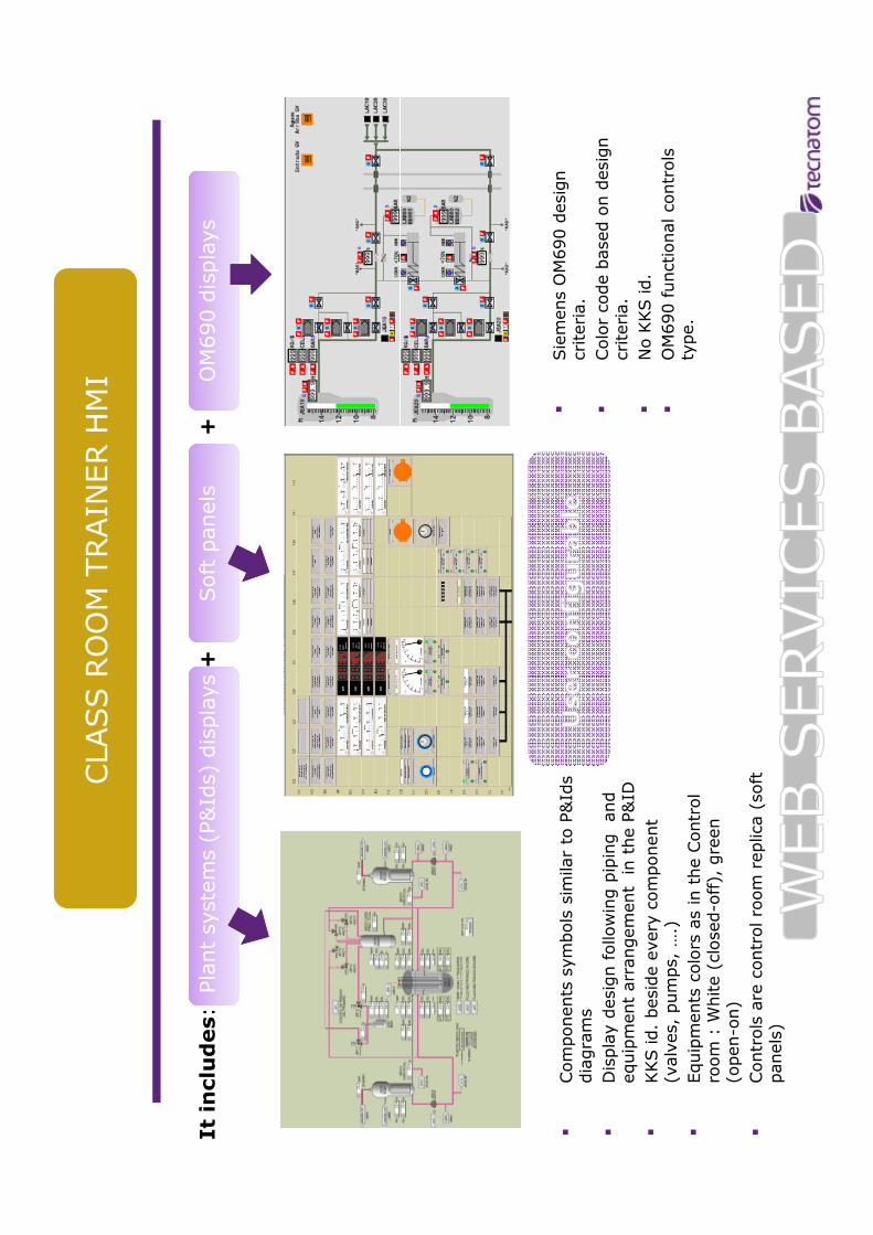
It includes: Plant systems (P&Ids) displays +
Soft panels +
OM690 displays
displays
CLASS ROOM TRAINER HMI
17
�Components symbols similar to P&Ids
diagrams
�Display design following piping and
equipment arrangement in the P&ID
�KKS id. beside every component
(valves, pumps, ….)
�Equipments colors as in the Control
room : W
hite (closed-off), green
(open-on)
�Controls are control room replica (soft
panels)
�Siemens OM690 design
criteria.
�Color code based on design
criteria.
�No KKS id.
�OM690 functional controls
type.

I/O INTERFACE FOR ATUCHA II SIM
ULATOR
18
INSTALLATION
I-O CARDS
REAR PANELS

Within the project scope, Tecnatom will supply:
Pilot project on training m
aterial generation: 5 plant systems will
be described (training perspective)
TRAINING MATERIAL ANDKNOW-HOW TRANSFER
19
Sim
ulator training scenarios (Ten scenarios will be designed)
Customer instructors will be qualified on:
�Training in simulator techniques
�Training follow up
�Class assessment
�Simulator training scenarios design

To provide a class room trainer in 15 m
onths including the
main plant systems.
Moderator and coolant: independent systems.
Singular core design: with inclined control rods, natural
uranium, on-line refueling m
achine system.
PROJECT DIFFICULTIES AND CHALLENGES (1/2)
20
Plant systems m
odeling extended to two-phase flow
phenomena: Main and auxiliary feedwater, Turbine,
Condensate, Containment….using TRAC_RT.
Separate input basedecksand m
ultiple TRAC_RT sim
ulation
environments.
Heavy water properties had to be considered within the
therm
alhydraulicmodels.

Control room instrumentation sometimes obsolete or
decommissioned (instruments unavailable)
Plant design documentation difficulties: old, under
development and changing (Plant under construction)
PROJECT DIFFICULTIES AND CHALLENGES (2/2)
21
development and changing (Plant under construction)
Operating plant procedures are being drawn up.
Validation. Unavailability of actual process data.

�Difficulties and challenges seem to be overcome
�Project schedule without delays (next May due delivery
of Class room trainer Phase 1)
�Customer soundly involved and orientated to be O&M
PROJECT PRESENTSITUATION
22
�Customer soundly involved and orientated to be O&M
self-sufficient.
�“As built” revision desirable once the plant project is
completed