Embed Size (px)
Citation preview

NUCLEAR OPERATING CORPORATION
Matthew W. SunseriVice President Operations and Plant Manager
November 16, 2007WO 07-0028
U. S. Nuclear Regulatory CommissionATTN: Document Control DeskWashington, DC 20555
Reference: 1) Letter ET 07-0004, dated March 14, 2007, from T. J. Garrett,WCNOC, to USNRC
2) Letter dated August 8, 2007, from J. W. Lubinski, USNRC, toR. A. Muench, WCNOC
3) Letter ET 07-0039, dated August 31, 2007, from T. J. Garrett,WCNOC, to USNRC
4) Letter ET 07-0041, dated September 20, 2007, from T. JGarrett, WCNOC, to USNRC
Subject: Docket No. 50-482: Response to Request for AdditionalInformation Relating to Replacement of the Main Steam andFeedwater Isolation Valves and Controls
Gentlemen:
Reference 1 provided a license amendment request that proposed revisions to TechnicalSpecification (TS) 3.3.2, "Engineered Safety Feature Actuation System (ESFAS)Instrumentation," TS 3.7.2, "Main Steam Isolation Valves (MSIVs)," and TS 3.7.3, "MainFeedwater Isolation Valves (MFIVs)" based on a planned modification to replace the MSIVsand associated actuators, MFIVs and associated actuators. This modification also plannedreplacement of the Main Steam and Feedwater Isolation System (MSFIS) controls.
On August 2, 2007, Wolf Creek Nuclear Operating Corporation (WCNOC) personnel met withthe NRC staff to discuss five issues identified by the NRC associated with the review of theMSFIS controls modification. Subsequently, the NRC issued Reference 2, in which the NRCstaff accepted the MSFIS controls modification license amendment request for review. Thisletter identified 5 issues requiring a response from WCNOC. Reference 3 provided responsesto the 5 issues. With regard to issue 1, WCNOC provided in Reference 4 a difference analysisof RTCA DO-254/EUROCAE ED-80, "Design Assurance Guidance for Airborne ElectronicHardware," to Institute of Electrical and Electronics Engineers (IEEE) Std 7-4.3.2-2003, "IEEE
PO. Box 411 / Burlington, KS 66839 / Phone: (620) 364-8831
An Equal Opportunity Employer M/F/HCNVET IA ,n

WO 07-0028Page 2
Standard Criteria for Digital Computers in Safety Systems of Nuclear Power GeneratingStations." In a teleconference between NRC staff and WCNOC personnel on September 25,2007, WCNOC agreed to provide a draft matrix of the IEEE Std 7-4.3.2-2003 requirements asthey pertain to the MSFIS controls design. The draft matrix was provided by electronic mail onOctober 12, 2007. Enclosure I provides the Matrix of IEEE 7-4.3.2 Requirements to MSFISControls Design.
Enclosure I provides the proprietary WCNOC, "Matrix of IEEE 7-4.3.2 Requirements to MSFISControls Design," Rev. 0. Enclosure II provides the non-proprietary WCNOC, "Matrix of IEEE:7-4.3.2 Requirements to MSFIS Controls Design," Rev. 0. As Enclosure I contains informationproprietary to WCNOC, it is supported by an affidavit signed by WCNOC, the owner of theinformation. The affidavit sets forth the basis on which the information may be withheld frompublic -disclosure by the Commission and addresses with specificity the considerations listed in'paragraph (b)(4) of 10 CFR 2.390 of the Commission's regulations. Accordingly, it isrespectfully requested that the information, which is proprietary to WCNOC, be withheld from.public disclosure in accordance with 10 CFR 2.390 of the Commission's regulations. Thisaffidavit is contained in Enclosure Ill.
The additional information provided in the Enclosures do not impact the conclusions of the NoSignificant Hazards Consideration provided in Reference 1. In accordance with 10 CFR 50.91,a copy of this submittal is being provided to the designated Kansas State official.
This letter contains no commitments. If you have any questions concerning this matter, pleasecontact me at (620) 364-4008, or Mr. Kevin Moles, Manager Regulatory Affairs at (620) 364-4126.
Sincerely,
Matthew W. Sunseri
MWS/rlt
Enclosures I - Matrix of IEEE 7-4.3.2 Requirements to MSFIS Controls. Design, Rev. 0(Proprietary)
II - Matrix of IEEE 7-4.3.2 Requirements to MSFIS Controls Design, Rev. 0(Non-Proprietary)
Ill - WCNOC Affidavit for Withholding Proprietary Information from PublicDisclosure
cc: E. E. Collins (NRC), w/eT. A. Conley (KDHE), w/e (Enclosure II only)J. N. Donohew (NRC), w/eV. G. Gaddy (NRC), w/eSenior Resident Inspector (NRC), w/e

WO 07-0028Page 3
STATE OF KANSAS
COUNTY OF COFFEY
))
Matthew W. Sunseri, of lawful age, being first duly sworn upon oath says that he is VicePresident Operations and Plant Manager of Wolf Creek Nuclear Operating Corporation; that hehas read the foregoing document and knows the contents thereof; that he has executed thesame for and on behalf of said Corporation with full power and authority to do so; and that thefacts therein stated are true and correct to the best of his knowledge, information and belief.
Matthew W. SunseriVice President Operations and Plant Manager
SUBSCRIBED and sworn to before me this IL9 1day offly. 2007.
0 -''" * RHONDA L. TIEMEYEROFFIALz
l EAL.-- MY COMMISSION EXPIRESJanuary 11,2010
Notary Public
Expiration Date at) / 0

Enclosure II to WO 07-0028
Matrix of IEEE 7-4.3.2 Requirements to MSFIS Controls Design, Rev. 0Non-Proprietary

NON-PROPRIETARY
MATRIX OF IEEE 7-4.3.2 REQUIREMENTS TO MSFIS CONTROLS DESIGN
Sections 1, 2, and 3 of IEEE 7-4.3.2 are Scope, References, and Definitions and Abbreviations, respectively. They are not included in the below matrix as they are consideredadministrative information.IEEE 7-4.3.2-2003 Requirements IEEE 603-1998 WCNOC Position4. Safety system design basis 4. Safety system design basis The main steam supply system design basis is provided in Section 10.3.1.1 ofNOTE-See Annex A for more information about the A specific basis shall be the USAR.relationship of this standard to IEEE Std 603-1998. established for the design of The main feedwater system design basis is provided in Section 10.4.7 of theNo requirements beyond IEEE Std 603-1998 are each safety system of the USAR.necessary (see also Annex B). nuclear power generating station. The main steam and feedwater isolation controls design basis is provided in
The design basis shall also beavailable as needed to facilitate Section 7.3.7 of the USAR.the determination of theadequacy of the safety system, The design basis of the systems are not changed with the modifications to theincluding design changes. The valves and controls.design basis shall be consistentwith the requirements ofANSI/ANS 51.1-1983 orANSI/ANS 52.1-1983 and shalldocument as a minimum: (SeeIEEE document for thisinformation)
5. Safety system criteria None RequiredThe following subclauses list the safety system criteria inthe order they are listed in IEEE Std 603-1998. For somecriteria, there are no additional requirements beyond whatis stated in IEEE Std 603-1998. For other criteria,additional requirements are described in 5.1 through 5.15.
5.1 Single-failure criterion 5.1 Single-failure criterion The Advanced Logic System (ALS) has been architected such that no singleNo requirements beyond IEEE Std 603-1998 are The safety systems shall perform failure shall prevent the system from performing the safety function. CSnecessary (see also Annex B). all safety functions required for a Innovations (CSI) 6101-00006, MSFIS Safety Assessment," provides a
design basis event in the detailed functional failure path analysis as well as a component level failurepresence of modes and effects analysis (FMEA) to ensure the single failure criterion is meta) Any single detectable failure with in the ALS. Further, the System Reliability Analysis for Advance Logicwithin the safety systems System includes a FMEA which shows that the single failure criterion is metconcurrent with all identifiable but for all creditable single failures and all failures caused by the single failure.nondetectable failures.b) All failures caused by thesingle failure. Referencesc) All failures and spurious CSI 6101-00006 (Enclosure 36 to ET 07-0022)]system actions that cause or are WCNOC System Reliability Analysis for Advanced Logic System (Enclosurecaused by the design basis event VII to ET 07-0008)requiring the safety functions.
The single failure could occurprior to, or at any time during, the
1 Rev. 0

NON-PROPRIETARY
IEEE 7-4.3.2-2003 Requirements IEEE 603-1998 WCNOC Position
design basis event for which thesafety system is required tofunction. The single-failurecriterion applies to the safetysystems whether control is byautomatic or manual means.IEEE Std 379-1994 providesguidance on the application ofthe single-failure criterion. (Seealso [B3].) IEEE Std 7-4.3.2-1993addresses common causefailures for digital computers.
This criterion does not invokecoincidence (or multiple-channel)logic within a safety group;however, the application ofcoincidence logic may evolvefrom other criteria orconsiderations to maximize plantavailability or reliability. Anevaluation has been performedand documented in otherstandards to show that certainfluid system failures need not beconsidered in the application ofthis criterion [B3]. Theperformance of a probabilisticassessment of the safetysystems may be used todemonstrate that certainpostulated failures need not beconsidered in the application ofthe criterion. A probabilisticassessment is intended toeliminate consideration of eventsand failures that are not credible;it shall not be used in lieu of thesingle-failure criterion. IEEE Std352-1987 and IEEE Std 577-1976 provide guidance forreliability analysis.
Where reasonable indicationexists that a design that meetsthe single-failure criterion maynot satisfy all the reliability
2 Rev. 0
2 Rev. 0
NON-PROPRIETARY
IEEE 7-4.3.2-2003 Requirements IEEE 603-1998 [WCNOC Positionrequirements specified in Clause4, item i) of the design basis, aprobabilistic assessment of thesafety system shall beperformed. The assessment shallnot be limited to single failures. Ifthe assessment shows that thedesign basis requirements arenot met, design features shall beprovided or correctivemodifications shall be made toensure that the system meets thespecified reliability requirements.
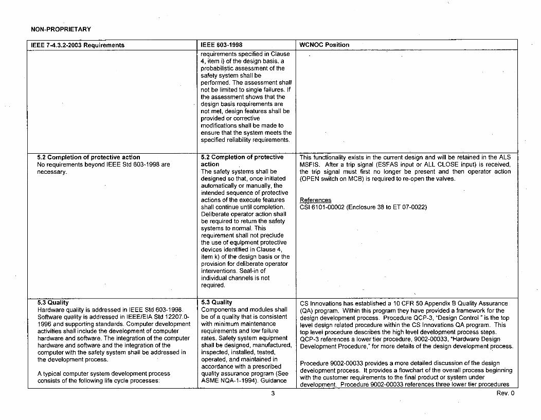
5.2 Completion of protective actionNo requirements beyond IEEE Std 603-1998 arenecessary.
5.2 Completion of protectiveactionThe safety systems shall bedesigned so that, once initiatedautomatically or manually, theintended sequence of protectiveactions of the execute featuresshall continue until completion.Deliberate operator action shallbe required to return the safetysystems to normal. Thisrequirement shall not precludethe use of equipment protectivedevices identified in Clause 4,item k) of the design basis or theprovision for deliberate operatorinterventions. Seal-in ofindividual channels is notrequired.
This functionality exists in the current design and will be retained in the ALSMSFIS. After a trip signal (ESFAS input or ALL CLOSE input) is received,the trip signal must first no longer be present and then operator action(OPEN switch on MCB) is required to re-open the valves.
ReferencesCSI 6101-00002 (Enclosure 38 to ET 07-0022)
5.3 QualityHardware quality is addressed in IEEE Std 603-1998.Software quality is addressed in IEEE/EIA Std 12207.0-1996 and supporting standards. Computer developmentactivities shall include the development of computerhardware and software. The integration of the computerhardware and software and the integration of thecomputer with the safety system shall be addressed inthe development process.
A typical computer system development processconsists of the following life cycle processes:
5.3 QualityComponents and modules shallbe of a quality that is consistentwith minimum maintenancerequirements and low failurerates. Safety system equipmentshall be designed, manufactured,inspected, installed, tested,operated, and maintained inaccordance with a prescribedquality assurance program (SeeASME NQA-1-1994). Guidance
CS Innovations has established a 10 CFR 50 Appendix B Quality Assurance(QA) program. Within this program they have provided a framework for thedesign development process. Procedure QCP-3, "Design Control " is the toplevel design related procedure within the CS Innovations QA program. Thistop level procedure describes the high level development process steps.QCP-3 references a lower tier procedure, 9002-00033, "Hardware DesignDevelopment Procedure," for more details of the design development process.
Procedure 9002-00033 provides a more detailed discussion of the designdevelopment process. It provides a flowchart of the overall process beginningwith the customer requirements to the final product or system underdevelopment. Procedure 9002-00033 references three lower tier procedures
Rev. 03 3 Rev. 0
NON-PROPRIETARY
IEEE 7-4.3.2-2003 Requirements IEEE 603-1998 WCNOC Position
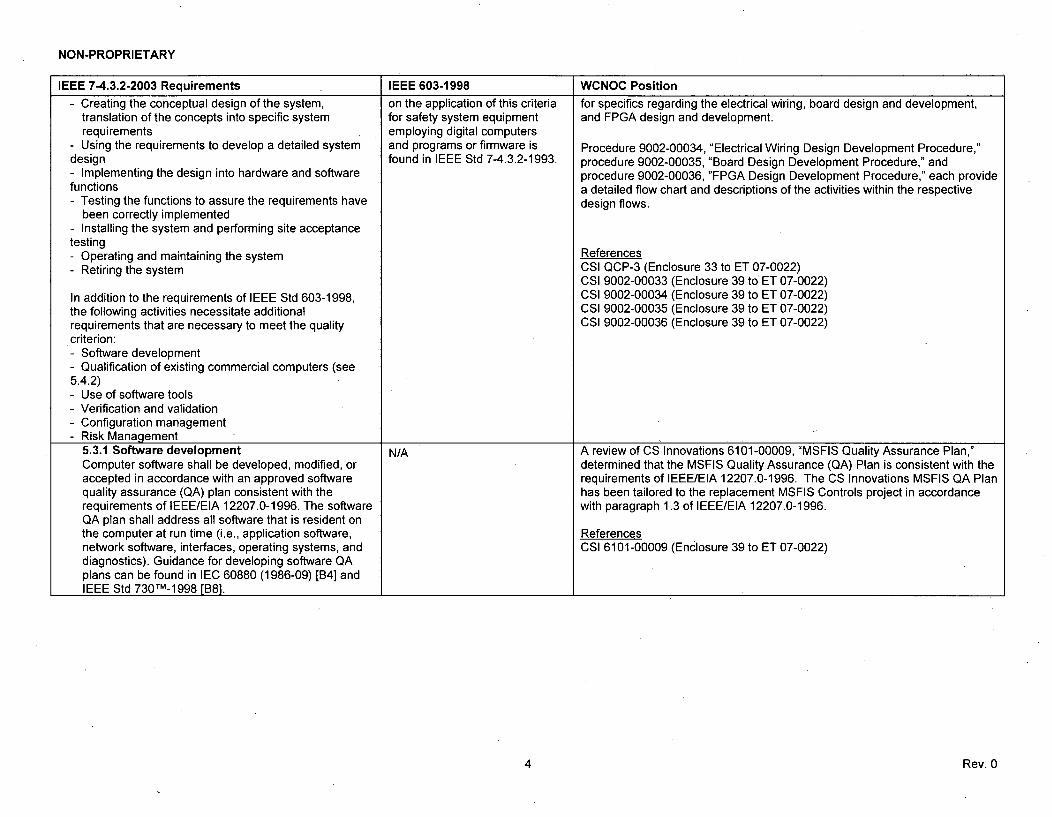
- Creating the conceptual design of the system, on the application of this criteria for specifics regarding the electrical wiring, board design and development,translation of the concepts into specific system for safety system equipment and FPGA design and development.requirements employing digital computers
- Using the requirements to develop a detailed system and programs or firmware is Procedure 9002-00034, "Electrical Wiring Design Development Procedure,"design found in IEEE Std 7-4.3.2-1993. procedure 9002-00035, "Board Design Development Procedure," and- Implementing the design into hardware and software procedure 9002-00036, "FPGA Design Development Procedure," each providefunctions a detailed flow chart and descriptions of the activities within the respective- Testing the functions to assure the requirements have design flows.
been correctly implemented- Installing the system and performing site acceptancetesting- Operating and maintaining the system References- Retiring the system CSI QCP-3 (Enclosure 33 to ET 07-0022)
CSI 9002-00033 (Enclosure 39 to ET 07-0022)In addition to the requirements of IEEE Std 603-1998, CSI 9002-00034 (Enclosure 39 to ET 07-0022)the following activities necessitate additional CSI 9002-00035 (Enclosure 39 to ET 07-0022)requirements that are necessary to meet the quality CSI 9002-00036 (Enclosure 39 to ET 07-0022)criterion:- Software development- Qualification of existing commercial computers (see5.4.2)- Use of software tools- Verification and validation- Configuration management- Risk Management
5.3.1 Software development N/A A review of CS Innovations 6101-00009, "MSFIS Quality Assurance Plan,"Computer software shall be developed, modified, or determined that the MSFIS Quality Assurance (QA) Plan is consistent with theaccepted in accordance with an approved software requirements of IEEE/EIA 12207.0-1996. The CS Innovations MSFIS QA Planquality assurance (QA) plan consistent with the has been tailored to the replacement MSFIS Controls project in accordancerequirements of IEEE/EIA 12207.0-1996. The software with paragraph 1.3 of IEEE/EIA 12207.0-1996.QA plan shall address all software that is resident onthe computer at run time (i.e., application software, Referencesnetwork software, interfaces, operating systems, and CSI 6101-00009 (Enclosure 39 to ET 07-0022)diagnostics). Guidance for developing software QAplans can be found in IEC 60880 (1986-09) [B4] andIEEE Std 730TM-1998 [B8].
4 Rev. 0

NON-PROPRIETARY
IEEE 7-4.3.2-2003 Requirements IEEE 603-1998 WCNOC Position
5.3.1.1 Software quality metrics N/A CS Innovations 6101-00009, "MSFIS Quality Assurance Plan," includesThe use of software quality metrics shall be requirements for defect tracking and process improvement, and the CSconsidered throughout the software life cycle to Innovations 6101-00008, "MSFIS V&V Plan," includes the life cycle phaseassess whether software quality requirements are characteristics identified in IEEE 7-4.3.2, with the exception of performancebeing met. When software quality metrics are used, history. Performance history is maintained by the WCNOC maintenancethe following life cycle phase characteristics should program.be considered:- Correctness/Completeness (Requirements phase) References- Compliance with requirements (Design phase) CSI 6101-00009 (Enclosure 39 to ET 07-0022)- Compliance with design (Implementation phase) CSI 6101-00008 El- Functional compliance with requirements (Test (ncosure 27 to ET 07-0022)and Integration phase)- On-site functional compliance with requirements(Installation and Checkout phase)- Performance history (Operation and Maintenancephase)
The basis for the metrics selected to evaluatesoftware quality characteristics should be included inthe software development documentation. IEEE Std1061 TM-1998 [B131] provides a methodology for theapplication of software quality metrics.
5 Rev. 0

NON-PROPRIETARY
IEEE 7-4.3.2-2003 Requirements IEEE 603-1998 WCNOC Position
5.3.2 Software tools CS Innovations utilizes several software tools to achieve the final design of theSoftware tools used to support software development ALS. These software tools are critical aspects to ensure the final ALSprocesses and verification and validation (V&V) hardware meets the intended design objectives.processes shall be controlled under configurationmanagement. Tools selected for a particular project are controlled by configuration
management. Specifically, the tools utilized in the development life cycle for aOne or both of the following methods shall be used to particular project are configuration controlled and maintained with all filesconfirm the software tools are suitable for use: associated with that project.
a) A test tool validation program shall be developed to CS Innovations performs a tool assessment and qualification to ensure thatprovide confidence that the necessary features of the the tool(s) are capable of performing the particular design or verificationsoftware tool function as required. activity to an acceptable level of confidence. Tool assessment and
qualification has two fundamental aspects: 1) ensures the proper tool is usedb) The software tool shall be used in a manner such for a particular activity in the development of the ALS, and 2) identifies how thethat defects not detected by the software tool will be output of a particular tool is independently assessed within the V&V Activities.detected by V&V activities. Tool assessment and qualification is described in CS Innovations 6000-00010
"ALS Design Tools," Chapter 2. Tool assessment and qualification satisfy theTool operating experience may be used to provide methods described in IEEE 7-4.3.2, Section 5.3.2, to confirm the softwareadditional confidence in the suitability of a tool, tools are suitable for use.particularly when evaluating the potential forundetected defects. Tool operating experience has also been utilized for determining software tool
suitability. CS Innovations 6000-00010, "ALS Design Tools," discusses theexperience with the software tools being utilized.
ReferencesCSI 6000-00010 (Enclosure III to ET 07-0039)CSI 6101-00005 (Enclosure 31 to ET 07-0022)
6 Rev. 0

NON-PROPRIETARY
IEEE 7-4.3.2-2003 Requirements IEEE 603-1998 WCNOC Position
5.3.3 Verification and validationNOTE-See IEEE Std 1012-1998 and IEEE Std1012a TM-1998 [B10] for more information aboutsoftware V&V.
V&V is an extension of the program management andsystems engineering team activities. V&V is used toidentify objective data and conclusions (i.e., proactivefeedback) about digital system quality, performance,and development process compliance throughout thesystem life cycle. Feedback consists of anomalyreports, performance improvements, and qualityimprovements regarding the expected operatingconditions across the full spectrum of the system andits interfaces.
V&V processes are used to determine whether thedevelopment products of an activity conform to therequirements of that activity, and whether the systemperforms according to its intended use and userneeds. This determination of suitability includesassessment, analysis, evaluation, review, inspection,and testing of products and processes.
This standard adopts the IEEE Std 1012-1998terminology of process, activity and task, in whichsoftware V&V processes are subdivided into activities,which are further subdivided into tasks. The term V&Veffort is used to reference this framework of V&Vprocesses, activities, and tasks.
V&V processes shall address the computer hardwareand software, integration of the digital systemcomponents, and the interaction of the resultingcomputer system with the nuclear power plant.
The V&V activities and tasks shall include systemtesting of the final integrated hardware, software,firmware, and interfaces.
The software V&V effort shall be performed inaccordance with IEEE Std 1012-1998. The IEEE Std1012-1998 V&V requirements for the highest integritylevel (level 4) apply to systems developed using thisstandard (i.e., IEEE Std 7-4.3.2TM). See IEEE Std1012-1998 Annex B for a definition of integrity level 4software.
CS Innovations employs a V&V process for developing ALS basedapplications as described in 6101-00008, "MSFIS V&V Plan." CS Innovationsimplements a top level V&V plan for a particular application utilizing the ALS.The purpose of the V&V plan is to establish a consistent method for providingV&V sufficient to ensure safety and risk mitigation for the successfuldeployment of the system. For ALS based applications the V&V activities areperformed as part of the ongoing development and manufacturing process tofacilitate the timely detection of errors. The V&V activities are also performedto analyze and test the system with respect to the hardware interfaces,customer interfaces, and the safety related functionality.
CS Innovation's also performs ALS specific V&V activities that are independentof the replacement MSFIS Controls application V&V activities. ALS specificV&V activities are encompassed within the various procedures that deal withthe design development process. This includes procedures such as 9002-00033, "Hardware Design Development Procedure," 9002-00034, "ElectricalWiring Design Development Procedure," 9002-00035, "Board DesignDevelopment Procedure," and 9002-00036, "FPGA Design DevelopmentProcedure."
CS Innovations requires specific design reviews during each phase of theproject. The design review requirements are specified in procedures 9002-00024, "Electrical Wiring Design Review Procedure," 9002-00025, "BoardDesign Review Procedure," and 9002-00026, "FPGA Design ReviewProcedure." The required reviews are summarized as follows: d
7 Rev. 0
7 Rev. 0 -

NON-PROPRIETARY
IEEE 7-4.3.2-2003 Requirements IEEE 603-1998 WCNOC Position c, d
ReferencesCSI 6101-00008 (Enclosure 27 to ET 07-0022)CSI 9002-00036 (Enclosure 39 to ET 07-0022)CSI 6000-00008 (Enclosure 28 to ET 07-0022)CSI 9002-00034 (Enclosure 39 to ET 07-0022)CSI 9002-00035 (Enclosure 39 to ET 07-0022)
8 Rev. 0

NON-PROPRIETARY
IEEE 7-4.3.2-2003 Requirements IEEE 603-1998 WCNOC Position
5.3.4 Independent V&V (IV&V) requirements The CS Innovations V&V team is responsible for the V&V performance of allThe previous section addresses the V&V activities to phases of the system life cycle. The V&V organization performs reviews,be performed. This section defines the levels of audits, tests and analysis in addition to normal design reviews performedindependence required for the V&V effort. IV&V within the CS Innovations organization. The V&V team is responsible for theactivities are defined by three parameters: technical organization of the V&V activities, as well as creating the V&V plan for aindependence, managerial independence, and particular project. Given the fact that CS Innovations is a small company, theyfinancial independence. These parameters are have chosen to head the V&V team with the president of the company. Thisdescribed in Annex C of IEEE Std 1012-1998. ensures maximum familiarization with the design principles, features of the
ALS, customer requirements, etc. Although this does not constituteThe development activities and tests shall be verified independence between financial interests and the V&V effort, it doesand validated by individuals or groups with appropriate emphasize the focus on the V&V effort. Independence of the financial intereststechnical competence, other than those who was not deemed necessary given the president of the company has a highdeveloped the original design. interest in the V&V conducted in the best possible manner, and that the final
product outcome be of the highest quality possible.Oversight of the IV&V effort shall be vested in anorganization separate from the development and To ensure the V&V effort is a value added aspect of the overall process theprogram management organizations. The V&V effort V&V team is staffed with members familiar with all processes used within CSshall independently select Innovations from design, to manufacturing, to final test procedures anda) The segments of the software and system to be execution of the test equipment. This ensures a complete independentanalyzed and tested, understanding of the system, without support from the design team forb) The V&V techniques, and interpretations of the functionality of the system and the results of testing.c) The technical issues and problems upon which toact.
ReferencesThe V&V effort shall be allocated resources that are CSI 6101-00008 (Enclosure 27 ET 07-0022)independent of the development resources.
See Annex C of IEEE Std 1012-1998 for additionalguidance.5.3.5 Software configuration management N/A CS Innovations 6101-00005, "MSFIS Configuration Management Plan," isSoftware configuration management shall be based on IEEE Std 828 and the guidance in IEEE Std 1042. The Configurationperformed in accordance with IEEE Std 1042-1987. Management (CM) Plan identifies the configuration items that are underIEEE Std 828TM-1998 [B9] provides guidance for the configuration management, provides detailed requirements anddevelopment of software configuration management responsibilities for the change process, and defines the baselining process.plans. The CM Plan also includes detailed requirements for document and software
identification, release, archiving and audits.The minimum set of activities shall address thefollowing: Referencea) Identification and control of all software designs andcode CSI 6101-00005 (Enclosure 31 to ET 07-0022)b) Identification and control of all software designfunctional data (e.g., data templates and data bases)c) Identification and control of all software designinterfacesd) Control of all software design changese) Control of software documentation (user, operating,and maintenance documentation)
9 Rev. 0

NON-PROPRIETARY
IEEE 7-4.3.2-2003 Requirements IEEE 603-1998 WCNOC Position
f) Control of software vendor development activities forthe supplied safety system softwareg) Control and retrieval of qualification informationassociated with software designs and codeh) Software configuration auditsi) Status accounting
Some of these functions or documents may beperformed or controlled by other QA activities. In thiscase, the software configuration management planshall describe the division of responsibility.
A software baseline shall be established at appropriatepoints in the software life cycle process to synchronizeengineering and documentation activities. Approvedchanges that are created subsequent to a baselineshall be added to the baseline.
The labeling of the software for configuration controlshall include unique identification of each configurationitem, and revision and/or date time stamps for eachconfiguration item.
Changes to the software/firmware shall be formallydocumented and approved consistent with thesoftware configuration management plan. Thedocumentation shall include the reason for the change,identification of the affected software/firmware, and theimpact of the change on the system. Additionally, thedocumentation should include the plan forimplementing the change in the system (e.g.,immediately implementing the change, or schedulingthe change for a future version).
10 Rev. 0

NON-PROPRIETARY
IEEE 7-4.3.2-2003 Requirements IEEE 603-1998 WCNOC Position4 +
5.3.6 Software project risk managementSoftware project risk management is a tool for problemprevention: identifying potential problems, assessingtheir impact, and determining which potential problemsmust be addressed to assure that software qualitygoals are achieved. Risk management shall beperformed at all levels of the digital system project toprovide adequate coverage for each potential problemarea. Software project risks may include technical,schedule, or resource-related risks that couldcompromise software quality goals, and thereby affectthe ability of the safety computer system to performsafety related functions. Software project riskmanagement differs from hazard analysis, as definedin 3.1.31, in that hazard analysis is focused solely onthe technical aspects of system failure mechanisms.
N/A Risk management is addressed by CS Innovations 6101-00008, "MSFIS V&VPlan," in conjunction with procedure QCP-16, "Corrective Action." The Planspecifies the V&V activities which shall be completed at each phase of the lifecycle and the corresponding task iteration and audit policies.
ReferencesCSI 6101-00008 (Enclosure 27 to ET 07-0022)CSI QCP-16 (Enclosure33 to ET 07-0022)
I ±5.4 Equipment qualificationIn addition to the equipment qualification criteria providedby IEEE Std 603-1998, the requirements listed in 5.4.1and 5.4.2 are necessary to qualify digital computers foruse in safety systems.
5.4.1 Computer system testingComputer system qualification testing (see 3.1.36)shall be performed with the computer functioning withsoftware and diagnostics that are representative ofthose used in actual operation. All portions of thecomputer necessary to accomplish safety functions, orthose portions whose operation or failure could impairsafety functions, shall be exercised during testing. Thisincludes, as appropriate, exercising and monitoring thememory, the CPU, inputs and outputs, displayfunctions, diagnostics, associated components,communication paths, and interfaces. Testing shalldemonstrate that the performance requirementsrelated to safety functions have been met.
Qualification testing was performed on the ALS equipment per therequirements in WCNOC Specification J-105A. The qualification testing wascompleted with a full ALS rack, including all circuit cards installed, as well asthe assembly panel. The ALS rack was configured with the completefunctionality being the production system to be installed at Wolf CreekGenerating Station for the MSFIS Controls. This logic included all diagnosticsand self test capabilities of the ALS. The equipment was functionally testedbefore each test and after the completion of each test. During the qualificationtesting the equipment was actuated to perform the safety related functionwhile all diagnostics and self-test capabilities were functioning. Thequalification testing proved that the equipment was capable of accomplishingall safety functions and that the safety function was not impaired due to theself-test, diagnostics, or other features of the system not directly required toaccomplish the safety function.
ReferencesWCNOC Specification J-105A(Q) (Enclosure I to ET 07-0008)NI WCN-9715R, Rev. 0 (Enclosure VI to ET 07-0008)
5.4.2 Qualification of existing commercial The replacement MSFIS Controls have been developed by CS Innovations.computers The replacement MSFIS Controls is based on the ALS. CS Innovations hasNOTE-See Annex C for more information about developed the ALS for safety critical applications across multiple industries,commercial grade item dedication. with a particular focus on the nuclear industry. At the time the replacement
MSFIS Controls project began, CS Innovations was considered by WCNOC as11 Rev. 0

NON-PROPRIETARY
IEEE 7-4.3.2-2003 Requirements IEEE 603-1998 WCNOC Position
The qualification process shall be accomplished byevaluating the hardware and software design using thecriteria of this standard. Acceptance shall be basedupon evidence that the digital system or component,including hardware, software, firmware, and interfaces,can perform its required functions. The acceptanceand its basis shall be documented and maintained withthe qualification documentation.
In those cases in which traditional qualificationprocesses cannot be applied, an alternative approachto verify a component is acceptable for use in a safety-related application is commercial grade dedication.The objective of commercial grade dedication is toverify that the item being dedicated is equivalent inquality to equipment developed under a 10 CFR 50Appendix B program [B16].
The dedication process for the computer shall entailidentification of the physical, performance, anddevelopment process requirements necessary toprovide adequate confidence that the proposed digitalsystem or component can achieve the safety function.The dedication process shall apply to the computerhardware, software, and firmware that are required toaccomplish the safety function. The dedication processfor software and firmware shall, whenever possible,include an evaluation of the design process. Theremay be some instances in which a design processcannot be evaluated as part of the dedication process.For example, the organization performing theevaluation may not have access to the design processinformation for a microprocessor chip, to be used in thesafety system. In this case, it would not be possible toperform an evaluation to support the dedication.Because the dedication process involves all aspects oflife cycle processes and manufacturing quality,commercial grade item dedication should be limited toitems that are relatively simple in function relative totheir intended use.
Commercial grade item dedication involves preliminaryphase and detailed phase activities. These phaseactivities are described in 5.4.2.1 through 5.4.2.2.
a commercial supplier. CS Innovations indicated their intention to develop a 10CFR 50 Appendix B program during the execution of the replacement MSFISControls project. However, due to the fact CS Innovations was considered byWCNOC to be a commercial supplier at the beginning of the project, a thirdparty qualifier and dedicator was contracted by WCNOC to provide adequateconfidence that the ALS based replacement MSFIS Controls could achieve therequired safety function. Nutherm International was contracted by WCNOC tofulfill the role as the third party qualifier and dedicator.
CS Innovations has continued developing their 10 CFR 50 Appendix BProgram throughout the execution of the replacement MSFIS Controls Project.WCNOC performed a 10 CFR 50 Appendix B audit of the CS Innovationsprogram in September 2007. The results of the WCNOC audit found the CSInnovations Appendix B program to be satisfactory. The audit identified fouradministrative findings which did not effect the actual hardware developedunder the program. Therefore, WCNOC has added CS Innovations to theapproved supplier list for safety-related equipment. Subsequent orders fromWCNOC to CS Innovations may be safety-related orders, in this case a thirdparty qualifier and dedicator will not be necessary.
Nutherm International has provided the 1) qualification and 2) dedicationservices for the replacement MSFIS Controls Project.
1) The qualification of the equipment has been completed per WCNOCrequirements as identified in specification J-105A(Q). The qualification planand qualification results are provided in Nutherm International documentsWCN-9715P, "Nutherm Qualification Plan," Rev.1, and WCN-9715R, "NuthermQualification Report," Rev.0. As discussed in the response to 7-4.3.2 - 2003,Section 5.4.1, the equipment was exercising all portions of the functionalityrequired to accomplish the safety functions as well as all functionality of thebuilt-in self-testing, diagnostics, and other functionality not directly required toaccomplish the safety function.
2) The Nutherm International dedication process has identified the physical,performance, and dependability characteristics necessary to provide adequateconfidence that the proposed digital system can achieve the safety function.
The physical characteristics are those characteristics of the item which dealswith its cohstruction, materials, shape, form and fit, etc. The ALS physicalcharacteristics have been compared with the qualified equipment to ensuresimilarity. Any differences have been noted and evaluated for impact onqualification by the Nutherm Engineering Department.
The performance characteristics of the ALS are the operational criticalcharacteristics as determined by a technical evaluation. The performancecharacteristics have been verified through testing and analysis. Theperformance testincl verifies proper operation of the system and compliance
12 Rev. 0

NON-PROPRIETARY
IEEE 7-4.3.2-2003 Requirements IEEE 603-1998 WCNOC Positionwith the WCNOC specification J-105A. Nutherm International will performadetailed test procedure, TPS-9064, "Final Acceptance Testing for Main SteamFeedwater Isolation System (MSFIS) Rack," to verify the performance aspectsof the replacement MSFIS Controls.
The dependability characteristics of the ALS focuses on items such asreliability and built-in quality. The dependability of a digital system is stronglyinfluenced by the development process and the personnel involved in thedesign, development, verification, and validation of the digital equipment. TheALS is considered a software-based digital system which depends on highquality software utilized in the development to ensure the intended designobjective is achieved. However, the system does not contain, nor rely on,software or firmware for the execution of the system. Given the fact that theALS is software-based digital system, as described above, the dependabilityaspects of the ALS are critical to ensure adequate confidence that the ALScan achieve the safety function. The Nutherm International Final DedicationReport will provide the final results and conclusions regarding the dedicationprocess employed.
ReferencesWCNOC Specification J-105A(Q) (Enclosure I to ET 07-0008)NI WCN-9715R, Rev. 0 (Enclosure VI to ET 07-0008)
5.5 System integrityIn addition to the system integrity criteria provided byIEEE Std 603-1998, the following are necessary toachieve system integrity in digital equipment for use insafety systems:- Design for computer integrity- Design for test and calibration- Fault detection and self-diagnostics
13 Rev. 0

NON-PROPRIETARY
IEEE 7-4.3.2-2003 Requirements IEEE 603-1998 WCNOC Position
5.5.1 Design for computer integrityThe computer shall be designed to perform its safetyfunction when subjected to conditions, external orinternal, that have significant potential for defeating thesafety function. For example, input and outputprocessing failures, precision or roundoff problems,improper recovery actions, electrical input voltage andfrequency fluctuations, and maximum credible numberof coincident signal changes.
If the system requirements identify a safety systempreferred failure mode, failures of the computer shallnot preclude the safety system from being placed inthat mode. Performance of computer system restartoperations shall not result in the safety system beinginhibited from performing its function.
14 Rev. 0

NON-PROPRIETARY
IEEE 7-4.3.2-2003 Requirements IEEE 603-1998 WCNOC Position
5.5.2 Design for test and calibrationTest and calibration functions shall not adversely affectthe ability of the computer to perform its safetyfunction. Appropriate bypass of one redundantchannel is not considered an adverse effect in thiscontext. It shall be verified that the test and calibrationfunctions do not affect computer functions that are notincluded in a calibration change (e.g., setpointchange)..
V&V, configuration management, and QA shall berequired for test and calibration functions on separatecomputers (e.g., test and calibration computer) thatprovide the sole verification of test and calibration The on-line test capabilities of the ALS are fully contained within the ALSdata. V&V, configuration management, and QA shall system, thus no separate test systems are required.be required when the test and calibration function isinherent to the computer that is part of the safety The ALS does not implement setpoints, e.g., calibration settings for specificsystem. trip points, for the replacement MSFIS Controls. Therefore specific concerns
regarding the calibration and changing of setpoints do not apply.V&V, configuration management, and QA are notrequired when the test and calibration function isresident on a separate computer and does not provide Referencesthe sole verification of test and calibration data for the CSI 6000-00000 (Enclosure 37 to ET 07-0022)computer that is part of the safety system.
c,d
15 Rev. 0

NON-PROPRIETARY
IEEE 7-4.3.2-2003 Requirements IEEE 603-1998 WCNOC Position
5.5.3 Fault detection and self-diagnosticsComputer systems can experience partial failures thatcan degrade the capabilities of the computer system,but may not be immediately detectable by the system.Self-diagnostics are one means that can be used toassist in detecting these failures. Fault detection andself-diagnostics requirements are addressed in thissubclause.
The reliability requirements of the safety system shallbe used to establish the need for self-diagnostics. Selfdiagnostics are not required for systems in which Referencesfailures can be detected by alternate means in a timelymanner. If self-diagnostics are incorporated into the CSI 6000-00000 (Enclosure 37 to ETsystem requirements, these functions shall be subject S i 2.1, 2.7.1,sure.37 .4 07-0022)to the same V&V processes as the safety system Sections; 2.1, 2.7.1, 2.7.3, 7.4functions.
If reliability requirements warrant self-diagnostics, thencomputer programs shall incorporate functions todetect and report computer system faults and failuresin a timely manner. Conversely, self-diagnosticfunctions shall not adversely affect the ability of thecomputer system to perform its safety function, orcause spurious actuations of the safety function. Atypical set of self-diagnostic functions includes thefollowing:- Memory functionality and integrity tests (e.g.,PROM checksum and RAM tests)- Computer system instruction set (e.g., calculationtests)- Computer peripheral hardware tests (e.g.,watchdog timers and keyboards)- Computer architecture support hardware (e.g.,address lines and shared memory interfaces)- Communication link diagnostics (e.g., CRC checks)
Infrequent communication link failures that do notresult in a system failure or a lack of systemfunctionality do not require reporting.
When self-diagnostics are applied, the following self-diagnostic features shall be incorporated into thesystem design:a) Self-diagnostics during computer system startupb) Periodic self-diagnostics while the computer systemis operatingc) Self-diaqnostic test failure reportinq
16 Rev. 0

NON-PROPRIETARY
IEEE 7-4.3.2-2003 Requirements IEEE 603-1998 WCNOC Position
5.6 IndependenceIn addition to the requirements of IEEE Std 603-1998,data communication between safety channels orbetween safety and nonsafety systems shall not inhibitthe performance of the safety function.
IEEE Std 603-1998 requires that safety functions beseparated from nonsafety functions such that thenonsafety functions cannot prevent the safety systemfrom performing its intended functions. In digital systems,safety and nonsafety software may reside on the samecomputer and use the same computer resources.
Either of the following approaches is acceptable toaddress the previous issues:a) Barrier requirements shall be identified to provideadequate confidence that the nonsafety functions cannotinterfere with performance of the safety functions of thesoftware or firmware. The barriers shall be designed inaccordance with the requirements of this standard. Thenonsafety software is not required to meet theserequirements.b) If barriers between the safety software and nonsafetysoftware are not implemented, the nonsafety softwarefunctions shall be developed in accordance with therequirements of this standard.
Guidance for establishing communication independenceis provided in Annex E.
5.6 Independence5.6.1 Between redundantportions of a safety systemRedundant portions of a safetysystem provided for a safetyfunction shall be independent of,and physically separated from,each other to the degreenecessary to retain the capabilityof accomplishing the safetyfunction during and following anydesign basis event requiring thatsafety function.5.6.2 Between safety systemsand effects of design basiseventSafety system equipmentrequired to mitigate theconsequences of a specificdesign basis event shall beindependent of, and physicallyseparated from, the effects of thedesign basis event to the degreenecessary to retain the capabilityof meeting the requirements ofthis standard. Equipmentqualification in accordance with5.4 is one method that can beused to meet this requirement.5.6.3 Between safety systemsand other systemsThe safety system design shallbe such that credible failures inand consequential actions byother systems, as documented inClause 4, item h) of the designbasis, shall not prevent the safetysystems from meeting therequirements of this standard.5.6.3.1 Interconnectedequipmenta) Classification. Equipmentthat is used for both safety andnonsafety functions shall beclassil'ed aspart of the safetysystems. Isolation devices usedto effect a safety system
The ALS MSFIS will be installed in the existing Group 1 and Group 4cabinets, maintaining the current safety group separations. New switchesinstalled on the MCB to control both trains include physical barriers whichmeet the requirements of IEEE Std 384-1992.
The ALS MSFIS equipment has been seismically qualified by the Appendix Bsupplier, Nutherm International.
There are no changes from the existing MSFIS design.
c~d
17 Rev. 0
17 Rev. 0

NON-PROPRIETARY
IEEE 7-4.3.2-2003 Requirements IEEE 603-1998 WCNOC Position
boundary shall be classified aspart of the safety system.b) Isolation. No credible failureon the non-safety side of anisolation device shall prevent anyportion of a safety system frommeeting its minimumperformance requirements duringand following any design basisevent requiring that safetyfunction. A failure in an isolationdevice shall be evaluated in thesame manner as a failure ofother equipment in a safetysystem.5.6.3.2 Equipment in proximitya) Separation. Equipment inother systems that is in physicalproximity to safety systemequipment, but that is neither anassociated circuit nor anotherClass 1 E circuit, shall bephysically separated from thesafety system equipment to thedegree necessary to retain thesafety systems capability toaccomplish their safety functionsin the event of the failure of non-safety equipment. Physicalseparation may be achieved byphysical barriers or acceptableseparation distance. Theseparation of Class 1 Eequipment shall be inaccordance with therequirements of IEEE Std 384-1992. (See [B13.)
b) Barrier. Physical barriersused to effect a safety systemboundary shall meet therequirements of 5.3, 5.4 and 5.5for the applicable conditionsspecil:ed in Clause 4, items g)and h) of the design basis.
There are no changes from the existing MSFIS design.
_____________________________________________________ I ______________________________ I
18 Rev. 0
18 Rev. 0

NON-PROPRIETARY
IEEE 7-4.3.2-2003 Requirements IEEE 603-1998 WCNOC Position
5.6.3.3 Effects of a single There are no changes from the existing MSFIS design.random failureWhere a single random failure ina nonsafety system can result ina design basis event, and alsoprevent proper action of a portionof the safety system designed toprotect against that event, theremaining portions of the safetysystem shall be capable ofproviding the safety functioneven when degraded by anyseparate single failure. See IEEEStd 379-1994 for the applicationof this requirement.5.6.4 Detailed criteria As described above, the IEEE Std 7-4.3.2-1993 requirements have been
IEEE Std 384-1992 provides applied to the ASU service and test connection.
detailed criteria for theindependence of Class 1 Eequipment and circuits [B11].IEEE Std 7-4.3.2-1993 provides Referencesguidance on the application ofthis criteria for the separation and CSI 6000-00000 (Enclosure 37 to ET 07-0022)
isolation of the data processing NI WCN-9715R, Rev. 0 (Enclosure VI to ET 07-0008)
functions of interconnectedcomputers.
19 Rev. 0

NON-PROPRIETARY
IEEE 7-4.3.2-2003 Requirements IEEE 603-1998 WCNOC Position
5.7 Capability for test and calibrationNo requirements beyond IEEE Std 603-1998 arenecessary.
5.7 Capability for testing andcalibrationCapability for testing andcalibration of safety systemequipment shall be providedwhile retaining the capability ofthe safety systems to accomplishtheir safety functions. The -
capability for testing andcalibration of safety systemequipment shall be providedduring power operation-and shallduplicate, as closely aspracticable, performance of thesafety function. Testing of Class1E systems shall be inaccordance with therequirements of IEEE Std 338-1987. Exceptions to testing andcalibration during poweroperation are allowed where thiscapability cannot be providedwithout adversely affecting thesafety or operability of thegenerating station. In this case:- Appropriate justification shall beprovided (e.g., demonstrationthat no practical design exists),- Acceptable reliability ofequipment operation shall beotherwise demonstrated, and- The capability shall be providedwhile the generating station isshut down.
The ALS includes the capability for a maintenance bypass function. Thereplacement MSFIS Controls implementation provides a maintenance bypassfor each of the Main Steam Isolation Valve (MSIV) and Main FeedwaterIsolation Valve (MFIV). When a single train is in bypass, the opposite trainmaintains the capability to perform the MSFIS safety function (also see theposition associated with Section 5.3.2).
5.8 Information displays 5.8.1 Displays for manually There are no changes from the existing MSFIS design.No requirements beyond IEEE Std 603-1998 are controlled actionsnecessary.
The display instrumentationprovided for manually controlledactions for which no automaticcontrol is pro- vided and thedisplay instrumentation requiredfor the safety systems toaccomplish their safety functionsshall be part of the safety
20 Rev. 0

NON-PROPRIETARY
IEEE 7-4.3.2-2003 Requirements IEEE 603-1998 WCNOC Position
systems and shall meet therequirements of IEEE Std 497-1981 [B10]. The design shallminimize the possibility ofambiguous indications that couldbe confusing to the operator.
5.8.2 System status indication The ALS MSFIS includes a "Summary Trouble Alarm" for each train on the
MCB. This alarm will activate on any system fault.
Display instrumentation shallprovide accurate, complete, andtimely information pertinent tosafety system status. Thisinformation shall includeindication and identification ofprotective actions of the senseand command features andexecute features. The designshall minimize the possibility ofambiguous indications that couldbe confusing to the operator. Thedisplay instrumentation providedfor safety system statusindication need not be part of thesafety systems.
5.8.3 Indication of bypasses The ALS MSFIS includes a STATUS indicator for each train on the MCB. This
will indicate if any valve is in bypass mode.If the protective actions of some
part of a safety system havebeen bypassed or deliberatelyrendered inoper- ative for anypurpose other than anoperating bypass, continuedindication of this fact for eachaffected safety group shall beprovided in the control room.
a) This display instrumentationneed not be part of the safetysystems.b) This indication shall beautomatically actuated if thebypass or inoperative conditionis expected to occur more
21 Rev. 0
21 Rev. 0
NON-PROPRIETARY
IEEE 7-4.3.2-2003 Requirements IEEE 603-1998 WCNOC Position
frequently than once a year, andis expected to occur when theaffected system is required tobe operable.c) The capability shall exist inthe control room to manuallyactivate this display indication.
5.8.4 LocationThe Summary Trouble Alarm and Status indicators are located on the MCB
Information displays shall be alarm and status panels in the same locations as the existing system.
located accessible to theoperator. Information displaysprovided for manually controlled Referencesprotective actions shall be visible CSI 6000-00000 (Enclosure 37 to ET 07-0022)from the location of the controlsused to affect the actions.
5.9 Control of access 5.9 Control of access Physical access is controlled by plant security. Administrative controls limitNo requirements beyond IEEE Std 603-1998 are The design shall permit the access when the ASU is connected.necessary. administrative control of access
to safety system equipment.These administrative controlsshall be supported by provisionswithin the safety systems, byprovision in the generatingstation design, or by acombination thereof.
5.10 Repair 5.10 Repair The ALS MSFIS contains extensive on-line continuous self-test, failureNo requirements beyond IEEE Std 603-1998 are The safety systems shall be detection and isolation, and off-line diagnostic aids.necessary. designed to facilitate timely
recognition, location,replacement, repair, andadjustment of malfunctioningequipment.
5.11 Identification 5.11 IdentificationTo. provide assurance that the required computer system In order to provide assurancehardware and software are installed in the appropriate that the requirements given insystem configuration, the following identification this standard can be appliedrequirements specific to software systems shall be met:: during the design, construction,a) Firmware and software identification shall be used to maintenance, and operation ofassure the correct software is installed in the correct the plant, the followinghardware component.
22 Rev. 0

NON-PROPRIETARY
IEEE 7-4.3.2-2003 Requirements IEEE 603-1998 WCNOC Position
b) Means shall be included in the software such that theidentification may be retrieved from the firmware usingsoftware maintenance tools.c) Physical identification requirements of the digitalcomputer system hardware shall be in accordance withthe identification requirements in IEEE Std 603-1998.
requirements shall be met:
a) Safety system equipmentshall be distinctly identified foreach redundant portion of asafety system in accordance withthe requirements of IEEE Std384-1992 and IEEE Std 420-1982.
b) Components or modulesmounted in equipment orassemblies that are clearlyidentified as being in a singleredundant portion of a safetysystem do not themselvesrequire identification.
c) Identification of safety systemequipment shall bedistinguishable from anyidentifying markings placed onequipment for other purposes(e.g., identification of fireprotection equipment, phaseidentification of power cables).
d) Identification of safety systemequipment and its divisionalassignment shall not requirefrequent use of referencematerial.
e) The associateddocumentation shall be distinctlyidentified in accordance with therequirements of IEEE Std 494-1974 [B9].
f) The versions of computerhardware, programs, andsoftware shall be distinctlyidentified in accordance withIEEE Std 7-4.3.2-1993.
No changes to existing safety group identification (cabinet nameplates andcolor-coded wiring).
There are no changes from the existing MSFIS design.
There are no changes from the existing MSFIS design.
There are no changes from the existing MSFIS design.
There are no changes from the existing MSFIS design.
c,d
Rev. 023

NON-PROPRIETARY
IEEE 7-4.3.2-2003 Requirements IEEE 603-1998 WCNOC Position
5.12 Auxiliary features 5.12 Auxiliary features As one element of the Engineered Safety Features Actuation SystemNo requirements beyond IEEE Std 603-1998 are Auxiliary supporting features (ESFAS), the ALS MSFIS does not contain any auxiliary features as definednecessary. shall meet all requirements of here. The complete ALS MSFIS has been designed to meet this standard.
this standard.
Other auxiliary features thatperform a function that is notrequired for the safety systems toaccomplish their safety functions,and are part of the safetysystems by association (i.e., notisolated from the safety system)shall be designed to meet thosecriteria necessary to ensure thatthese components, equipment,and systems do not degrade thesafety systems below anacceptable level. Examples ofthese other auxiliary features areshown in Figure 3 and anillustration of the application ofthis criteria is contained in AnnexA.
5.13 Multi-unit stations 5.13 Multi-unit stations This is not applicable as WCGS is a single unit facility.No requirements beyond IEEE Std 603-1998 are The sharing of structures,necessary. systems, and components
between units at multi-unitgenerating stations is permissibleprovided that the ability tosimultaneously perform requiredsafety functions in all units is notimpaired. Guidance on thesharing of electrical powersystems between units iscontained-in IEEE Std 308-1991.Guidance on the application ofthe single failure criterion toshared systems is contained inIEEE Std 379-1994.
24 Rev. 0

NON-PROPRIETARY
IEEE 7-4.3.2-2003 Requirements IEEE 603-1998 WCNOC Position
5.14 Human factor considerations 5.14 Human factor Human factor considerations were a major design goal of the ALS MSFISNo requirements beyond IEEE Std 603-1998 are considerations project. All operator information is available on the front panels. Controls andnecessary. Human factors shall be indicators are clearly labeled and grouped and show the state of the system
considered at the initial stages for efficient evaluation of system status.and throughout the designprocess to assure that thefunctions allocated in whole or inpart to the human operator(s)and maintainer(s) can besuccessfully accomplished tomeet the safety system designgoals, in accordance with IEEEStd 1023-1988.
5.15 Reliability 5.15 Reliability The quantitative reliability goal established for the ALS MSFIS was to exceedNOTE-See Annex F for more information about the For those systems for which the two year mean time between failure (MTBF) of the existing MSFISreliability criterion. either quantitative or qualitative equipment. A System Reliability Analysis (SRA) was performed in accordance
reliability goals have been with IEEE Std 352-1987 and IEEE Std 577-1976. The SRA shows that theIn addition to the requirements of IEEE Std 603-1998, established, appropriate analysis reliability goal has been far exceeded.when reliability goals are identified, the proof of meeting of the design shall be performedthe goals shall include the software. The method for in order to confirm that such Referencesdetermining reliability may include combinations of goals have been achieved. IEEEanalysis, field experience, or testing. Software error Std 352-1987 and IEEE Std 577- VII to ET 07-0008)
recording and trending may be used in combination with 1976 provide guidance for
analysis, field experience, or testing. reliability analysis. Guidance on
the application of this criteria forsafety system equipmentemploying digital computers andprograms or firmware is found inIEEE Std 7-4.3.2-1993.
6. Sense and command features-functional and 6. Sense and commanddesign requirements features-functional andNo requirements beyond IEEE Std 603-1998 are design requirementsnecessary. In addition to the functional and
design requirements in Clause 5,the requirements listed in 6.1through 6.8 shall apply to thesense and command features.
6.1 Automatic control This requirement is not applicable to the extent that the MSFIS does notMeans shall be provided to automatically initiate protective actions, however as an element of the ESFAS,automatically initiate and control the MSFIS provides automatic MSIV and MFIV closure, without operatorall protective actions except as
25Re.25 Rev. 0

NON-PROPRIETARY
IEEE 7-4.3.2-2003 Requirements I IEEE 603-1998 1 WCNOC Positionjustified in Clause 4, item e). Thesafety system design shall besuch that the operator is notrequired to take any action priorto the time and plant conditionsspecified in Clause 4, item e)following the onset of eachdesign basis event. At the optionof the safety system designer,means may be provided toautomatically initiate and controlthose protective actions ofClause 4, item e).
6.2 Manual controlMeans shall be provided in thecontrol room toa) Implement manual initiation atthe division level of theautomatically initiated protectiveactions. The means provided shallminimize the number of discreteoperator manipulations and shalldepend on the operation of aminimum of equipment consistentwith the constraints of 5.6.1.b) Implement manual initiationand control of the protectiveactions identified in Clause 4,item e) that have not beenselected for automatic controlunder 6.1. The displaysprovided for these actions shallmeet the requirements of 5.8.1.c) Implement the manualactions necessary to maintainsafe conditions after theprotective actions arecompleted as specified inClause 4, item j). Theinformation provided to theoperators, the actions requiredof these operators, and thequantity and location ofassociated displays andcontrols shall be appropriate for
intervention, when commanded via the ESFAS trip input.
Main Control Board (MCB) MSFIS control functions are provided (essentiallyunchanged from the existing system) which meet this requirement.
26RvI26 Rev. 0

NON-PROPRIETARY
IEEE 7-4.3.2-2003 Requirements 3 IEEE 603-1998 WCNOC Position
the time period within whichthe actions shall beaccomplished and the numberof available qualified operators.Such displays and controls shallbe located in areas that areaccessible, located in anenvironment suitable for theoperator, and suitably arrangedfor operator surveillance andaction.
6.3 Interaction between the No change from the existing system of two trains of MSFIS.sense and command featuresand other systems
6.3.1 Requirements
Where a single credible event,including all direct andconsequential results of thatevent, can cause a non- safetysystem action that results in acondition requiring protectiveaction, and can concurrentlyprevent the protective action inthose sense and commandfeature channels designated toprovide principal protectionagainst the condition, one of thefollowing requirements shall bemet:
a) Alternate channels not subjectto failure resulting from the samesingle event shall be provided tolimit the consequences of thisevent to a value specified by thedesign basis. Alternate channelsshall be selected from thefollowing:
1) Channels that sense aset of variables different fromthe principal channels.2) Channels that useequipment different from thatof the principal channels to
27 Rev. 0

NON-PROPRIETARY
IEEE 7-4.3.2-2003 Requirements [ IEEE 603-1998 1 WCNOC PositionIEEE 7-4.3.2-2003 Requirements IEEE 603-1998 WCNOC Position
sense the same variable.3) Channels that sense aset of variables different fromthose of the principalchannels using equipmentdifferent from that of theprincipal channels.
4) Both the principal andalternate channels shall bepart of the sense andcommand features.
b) Equipment not subject tofailure caused by the same singlecredible event shall be providedto detect the event and limit theconsequences to a valuespecified by the design bases.Such equipment is considered apart of the safety system. SeeFigure 5 for a decision chart forapplying the requirements of thisclause.
6.3.2 Provisions
Provisions shall be included sothat the requirements in 6.3.1can be met in conjunction withthe requirements of 6.7 if achannel is in maintenancebypass. These provisions includereducing the requiredcoincidence, defeating the non-safety system signals taken fromthe redundant channels, orinitiating a protective action fromthe bypassed channel.
6.4 Derivation of system inputs
To the extent feasible andpractical, sense and commandfeature inputs shall be derivedfrom signals that are directmeasures of the desiredvariables as specified in thedesign basis.
No change from the existing system. Only one train of MSFIS is required toclose a valve.
No change from the existing system. Each train of ALS MSFIS utilizesindependent inputs from switches on the MCB and valve positioninstrumentation on the valve actuators.
28 Rev. 0

NON-PROPRIETARY
IEEE 7-4.3.2-2003 Requirements f IEEE 603-1998 WCNOC Position
6.5 Capability for testing andcalibration
6.5.1 Checking the operationalavailabilityMeans shall be provided forchecking, with a high degree ofconfidence, the operationalavailability of each sense andcommand feature input sensorrequired for a safety functionduring reactor operation. Thismay be accomplished in variousways; for example:
a) By perturbing the monitoredvariable,
b) Within the constraints of 6.6,by introducing and varying, asappropriate, a substitute input tothe sensor of the same nature asthe measured variable, orc) By cross-checking betweenchannels that bear a knownrelationship to each other andthat have read- outs available.
6.5.2 Assuring the operationalavailability
One of the following means shallbe provided for assuring theoperational availability of eachsense and command featurerequired during the post-accidentperiod:
a) Checking the operationalavailability of sensors by use ofthe methods described in 6.5.1.
b) Specifying equipment that isstable and the period of time itretains its calibration during thepost- accident time period.
ALS MSFIS continuous self-test functions include all of the MSFIS inputs andthe existing manual system test capabilities are retained. This includescomplete testing of the safety function from the ESFAS input to the valveactuation outputs.
ALS MSFIS provides continuous self-test features and extensive redundancywithin each train. Failures are annunciated in the Control Room.
29 Rev. 0

NON-PROPRIETARY
IEEE 7-4.3.2-2003 Requirements IEEE 603-1998 1 WCNOC Position
6.6 Operating bypassesWhenever the applicablepermissive conditions are notmet, a safety system shallautomatically prevent theactivation of an operating bypassor initiate the appropriate safetyfunction(s). If plant conditionschange so that an activatedoperating bypass is no longerpermissible, the safety systemshall automatically accomplishone of the following actions:
a) Remove the appropriateactive operating bypass(es).b) Restore plant conditions sothat permissive conditions onceagain exist.c) Initiate the appropriate safetyfunction(s).
6.7 Maintenance bypass
Capability of a safety system toaccomplish its safety functionshall be retained while sense andcommand features equipment isin maintenance bypass. Duringsuch operation, the sense andcommand features shouldcontinue to meet therequirements of 5.1 and 6.3.NOTE-For portions of the senseand command features thatcannot meet the requirements of5.1 and 6.3 when in maintenancebypass, acceptable reliability ofequipment operation shall bedemonstrated (e.g., that theperiod allowed for removal fromservice for maintenance bypassis sufficiently short, or additionalmeasures are taken, or both, toensure there is no significantdetrimental effect on overall
This -requirement is not applicable. The ALS MSFIS does not include anyoperating bypass functions.
If one train of ALS MSFIS is in maintenance bypass, the other train retains thecapability to perform the safety function. Administrative controls prevent bothtrains from being in bypass simultaneously.
30 Rev. 0
30 Rev. 0

NON-PROPRIETARY
IEEE 7-4.3.2-2003 Requirements IEEE 603-1998 WCNOC Position
sense and command featureavailability).
6.8 Setpoints This requirement is not applicable to ALS MSFIS. There are no analog inputs
The allowance for uncertainties or setpoints.between the process analyticallimit documented in Clause 4,item d) and the device setpointshall be determined using adocumented methodology. Referto ANSI/ISA S67.04-1994.
Where it is necessary to providemultiple setpoints for adequateprotection for a particular modeof operation or set of operatingconditions, the design shallprovide positive means ofensuring that the more restrictivesetpoint is used when required.The devices used to preventimproper use of less restrictivesetpoints shall be part of thesense and command features.
7. Execute features-functional and design In addition to the functional andrequirements design requirements in Clause 5,No requirements beyond IEEE Std 603-1998 are the requirements listed in 7.1necessary. through 7.5 shall apply to the
execute features.
7.1 Automatic control There are no changes from the existing MSFIS design.
Capability shall be incorporatedin the execute features to receiveand act upon automatic controlsignals from the sense andcommand features consistentwith Clause 4, item d) of thedesign basis.
7.2 Manual control There are no-changes from the existing MSFIS design. The ALS MSFIS inputs
If manual control of any actuated are prioritized in the logic, with the ESFAS "ALL CLOSE" input having the
component in the execute highest priority.
features is provided, the
31 Rev. 0
NON-PROPRIETARY
IEEE 7-4.3.2-2003 Requirements IEEE 603-1998 WCNOC Position
additional design features in theexecute features necessary toaccomplish such manual controlshall not defeat the requirementsof 5.1 and 6.2. Capability shall beprovided in the execute featuresto receive and act upon manualcontrol signals from the senseand command featuresconsistent with the design basis.
7.3 Completion of protectiveaction
The design of the executefeatures shall be such that, onceinitiated, the protective actions ofthe execute features shall go tocompletion. This requirementshall not preclude the use ofequipment protective devicesidentified in Clause 4, item k) ofthe design basis or the provisionfor deliberate operatorinterventions. When the senseand command features reset, theexecute features shall notautomatically return to normal;they shall require separate,deliberate operator action to bereturned to normal. After theinitial protective action has goneto completion, the executefeatures may require manualcontrol or automatic control (i.e.,cycling)
of specific equipment to maintaincompletion of the safety function.
7.4 Operating bypassWhenever the applicablepermissive conditions are notmet, a safety system shallautomatically prevent theactivation of an operating bypassor initiate the appropriate safetyfunction(s). If plant conditions
Following receipt of an ESFAS close signal, an MSIV or MFIV cannot beopened until the ESFAS signal is no longer present. This is consistent with thelogic of the existing system.
This requirement is not applicable. The ALS MSFIS does not include anyoperating bypass functions.
32 Rev. 0

NON-PROPRIETARY
IEEE 7-4.3.2-2003 Requirements IEEE 603-1998 WCNOC Position
change so that an activatedoperating bypass is no longerpermissible, the safety systemshall automatically accomplishone of the following actions:
a) Remove the appropriateactive operating bypass(es).
b) Restore plant conditions sothat permissive conditions onceagain exist.c) Initiate the appropriate safetyfunction(s).
7.5 Maintenance bypass If one train of ALS MSFIS is in maintenance bypass, the other train retains the
The capability of a safety system capability to perform the safety function. Administrative controls prevent bothto accomplish its safety function trains from being in bypass simultaneously.shall be retained while executefeatures equipment is inmaintenance bypass. Portions ofthe execute features with adegree of redundancy of oneshall be designed such that whena portion is placed inmaintenance bypass (i.e.,reducing temporarily its degree ofredundancy to zero), theremaining portions provideacceptable reliability.
33 Rev. 0

NON-PROPRIETARY
IEEE 7-4.3.2-2003 Requirements IEEE 603-1998 WCNOC Position
8. Power source requirementsNo requirements beyond IEEE Std 603-1998 arenecessary.
8.1 Electrical power sources
Those portions of the Class 1Epower system that are requiredto provide the power to the manyfacets of the safety system aregoverned by the criteria of thisdocument and are a portion ofthe safety systems. Specificcriteria unique to the Class 1 Epower systems are given in IEEEStd 308-1991.
8.2 Non-electrical powersources
Non-electrical power sources,such as control-air systems,bottled-gas systems, andhydraulic systems, required toprovide the power to the safetysystems are a portion of thesafety systems and shall providepower consistent with therequirements of this standard.Specific criteria unique to non-electrical power sources areoutside the scope of thisstandard and can be found inother standards. 11 [84, B5]
8.3 Maintenance bypassThe capability of the safetysystems to accomplish theirsafety functions shall be retainedwhile power sources are inmaintenance bypass. Portions ofthe power sources with a degreeof redundancy of one shall bedesigned such that when aportion is placed in maintenancebypass (i.e., reducing temporarilyits degree of redundancy tozero), the remaining portionsprovide acceptable reliability.
There are no changes from the existing MSFIS design.
This requirement is not applicable.
If one train of the NK DC bus feeding the MSFIS is in a maintenance bypass,the other MSFIS train retains the capability to perform the safety function.Administrative controls prevent both trains from being in bypasssimultaneously.
34 Rev. 0

Enclosure III to WO 07-0028
WCNOC Affidavit for Withholding Proprietary Information from Public Disclosure

AFFIDAVIT
STATE OF KANSAS ))ssCOUNTY OF COFFEY )
Before me, the undersigned authority, personally appeared Matthew W. Sunseri, who, being byme duly sworn according to law, deposes and says that he is authorized to execute this Affidaviton behalf of Wolf Creek Nuclear Operating Corporation (WCNOC), and that the averments offact set forth in this Affidavit are true and correct to the best of his knowledge, information, andbelief:
Matthew W. SunseriVice President Operations and Plant Manager
Sworn to and subscribpdbefore me this ..!1' dayof fb/enher ,2007
Notary Public
1

(1) I am Vice President Operations and Plant Manager, Wolf Creek Nuclear OperatingCorporation (WCNOC), and as such, I have been specifically delegated the function ofreviewing the proprietary information sought to be withheld from public disclosure inWCNOC's submittal of the Matrix of IEEE 7-4.3.2 Requirements to MSFIS ControlsDesign, and am authorized to apply for its withholding on behalf of WCNOC.
(2) I am making this Affidavit in conformance with the provisions of 10 CFR Section 2.390of the Commission's regulations and in conjunction with WCNOC letter WO 07-0028which includes the Matrix of IEEE 7-4.3.2 Requirements to MSFIS Controls Designaccompanying this Affidavit.
(3) I have personal knowledge of the criteria and procedures utilized by WCNOC indesignating information as a trade secret, privileged or as confidential commercial orfinancial information.
(4) Pursuant to the provisions of paragraph (b)(4) of Section 2.390 of the Commission'sregulations, the following is furnished for consideration by the Commission indetermining whether the information sought to be withheld from public disclosure shouldbe withheld.
(i) The information sought to be withheld from public disclosure is owned and hasbeen held in confidence by WCNOC.
(ii) The information is of a type customarily held in confidence by other organizationsand not customarily disclosed to the public. Based on a review of 10 CFR 2.390,the information is held in confidence if it falls in one or more of several types, therelease of which might result in the loss of an existing or potential competitiveadvantage, as follows:
(a) The information reveals the distinguishing aspects of a process (orcomponent, structure, tool, method, etc.) where prevention of its use by anyother company without license from WCNOC constitutes a competitiveeconomic advantage over other companies.
(b) It consists of supporting data, including test data, relative to a process (orcomponent, structure, tool, method, etc.), the application of which datasecures a competitive economic advantage, e.g., by optimization orimproved marketability.
(c) Its use by another company would reduce its expenditure of resources orimprove its competitive position in the design, assurance of quality, orlicensing a similar product.
(d) It is not the property of WCNOC, but must be treated as proprietary byWCNOC according to agreements with the owners of the information.
There are sound reasons behind the WCNOC position which include the following:
(a) It is information which is marketable in many ways.
2

(b) Use by other companies would put WCNOC at a competitive disadvantageby reducing their expenditure of resources at our expense.
(c) Each component of proprietary information pertinent to a particularcompetitive advantage is potentially as valuable as the total competitiveadvantage. If other companies acquire components of proprietaryinformation, any one component may be the key to the entire puzzle,thereby depriving WCNOC of a competitive advantage.
(iii) The information is being transmitted to the Commission in confidence and, underthe provisions of 10 CFR Section 2.390, it is to be received in confidence by theCommission.
(iv) The information sought to be protected is not available in public sources oravailable information has not been previously employed in the same originalmanner or method to the best of our knowledge and belief.
(v) The proprietary information sought to be withheld in this submittal is the Matrix ofIEEE 7-4.3.2 Requirements to MSFIS Controls Design.
The subject information could only be duplicated by competitors if they were toinvest time and effort equivalent to that invested by WCNOC provided they havethe requisite talent and experience.
Public disclosure of this information is likely to cause substantial harm to thecompetitive position of WCNOC because it would simplify design and evaluationtasks without requiring a commensurate investment of time and effort.
3