Embed Size (px)
Citation preview

OWNERS MANUALAll Models 24, 24W, & 24M
Attic Storage Lifting System
IMPORTANT! READ & SAVE THIS MANUAL!This manual includes essential safety and maintenance information. Read this before operating the Versa Lift!
Safety Rules.............2,3
How it Works...............4
Electrical...................4
Lift Controls................5
Loading Cargo.........6,7
Operation................8,9
Maintenance.........10,11
Troubleshooting...12,13
Programming Wireless
Remotes...........14
Parts List....................15
CONTENTS Page
Copyright © 2006 - 2015 BPGAll rights reserved.
Revised 2015January
Protected ByUS Patent 8,418,814US Patent 8,851,238US Patent 8,702,069
Byers Products Group9641 NW 6th Street
Oklahoma City, OK 73127Ph: 405-491-8550
www.bpghome.com
Floor-to-FloorHeight
LadderOpening
Lift Opening
Versa Rail
RemoteControl
Versa Lift
LiftingHead
Cables
Lifting Platform
Ladder
JoistHeight
Fig. 0
READ THIS BEFORE OPERATING THE VERSA LIFT
IMPORTANT: READ AND
UNDERSTAND THIS OWNERS MANUAL COMPLETELY BEFORE OPERATING THIS EQUIPMENT. SAVE THIS MANUAL AND REFER TO IT OFTEN TO REDUCE THE RISK OF SEVERE INJURY, OR DEATH.
ALL OPERATORS MUST
ACCIDENTS,
2
DO NOT OPERATE THIS EQUIPMENT IN DAMP, WET OR POORLY LIGHTED LOCATIONS or attic spaces and don’t expose it to rain. Do not use this equipment in the presence of flammable gases or liquids. Keep the work area clear of obstacles, cluttered areas invite injuries. Use only correctly grounded power outlets or extension cords. Never operate equipment without grounding!
WARNING!
DO NOT WORK ALONE IN A HOT ATTIC or if you have any health condition that could affect your balance, your mobility, or cause you to loose consciousness. If you have any diminished capacity, always work with another person in case you should need help. Don’t work in the attic in the heat of the day. You can quickly be overcome by heat exhaustion in a hot attic in just a matter of minutes. Morning hours are the coolest time to work in the attic.
WARNING!
WARNING! WHEN WORKING IN THE ATTIC, STAY ON DECKED AREAS. If you must enter non-decked areas, stay on joists. The materials between the joists will not support your weight and will collapse if you stand or sit on them. Be alert to overhead hazards, such as exposed nails. Be aware of and avoid openings, such as the ladder opening or the lift opening when you are working or moving around in the attic.
NEVER ALLOW PERSONS ON OR IN THE LIFT! NEVER SIT OR STAND ON THE LIFTING PLATFORM! ABSOLUTELY NO RIDERS! No person under 18 years of age should be allowed to operate this product. Children should be kept away from the lift when it is in operation. When not in use, lock the remote control and remove the key and store it where children cannot get it! This product can cause serious injury or death to a child who attempts to ride the lift or to lift others! When not in use, ALWAYS raise the lifting platform to the highest position and unplug the power cord to lift, lock the remote and store the key!
DANGER!
DANGER! NEVER STORE FLAMMABLE LIQUIDS IN YOUR ATTIC, such as gasoline, paint thinner, aerosol cans, or other solvent or fuel containing products, tools, or devices. Attic temperatures can cause containers to rupture and explosive fumes can reach ignition sources.
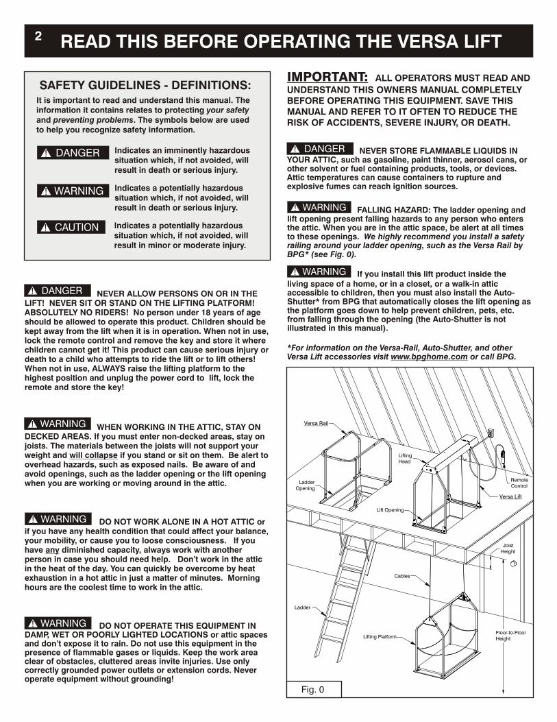
FALLING HAZARD: The ladder opening and lift opening present falling hazards to any person who enters the attic. When you are in the attic space, be alert at all times to these openings. We highly recommend you install a safety railing around your ladder opening, such as the Versa Rail by BPG* (see Fig. 0). If you install this lift product inside theliving space of a home, or in a closet, or a walk-in attic accessible to children, then you must also install the Auto-Shutter* from BPG that automatically closes the lift opening as the platform goes down to help prevent children, pets, etc. from falling through the opening (the Auto-Shutter is not illustrated in this manual). *For information on the Versa-Rail, Auto-Shutter, and other Versa Lift accessories visit www.bpghome.com or call BPG.
WARNING!
WARNING!
DANGER! Indicates an imminently hazardous situation which, if not avoided, will result in death or serious injury.
CAUTION! Indicates a potentially hazardous situation which, if not avoided, will result in minor or moderate injury.
SAFETY GUIDELINES - DEFINITIONS:It is important to read and understand this manual. The information it contains relates to protecting your safety and preventing problems. The symbols below are used to help you recognize safety information.
WARNING! Indicates a potentially hazardous situation which, if not avoided, will result in death or serious injury.
1. Never allow children or adolescents to operate the Versa Lift. No one under 18 years of age should be allowed to operate this equipment.
2. To avoid accidents and injury all operators must first read and understand this manual. It is unsafe for any person, regardless of age or experience, to operate this equipment without first learning the safety rules.
3. Protect children and visitors, their safety is your responsibility. Keep children out of the attic. Keep children and unfamiliar persons away from the lift during operation. When not in use, unplug the Versa Lift, lock the remote in the OFF position and remove the key. Store the key in a safe place away from the lift and out of reach of children.
4. Instruct children of the dangers of unauthorized use. This equipment is powerful and could cause severe injury or death if used by anyone but responsible adults!
5. Keep children out of the attic. The attic is extremely dangerous for small children, even when adults are present! Children are unaware of the dangers and can step off decked areas or fall through openings.
6. Never allow persons on or in the lift or the lifting platform. Absolutely no riders on this equipment! Any person riding the platform is likely to become caught between the lifting platform and the ceiling opening. Riding the platform is extremely dangerous and presents the following hazards:
Falling Hazard - head injury, broken limbs, death. Crushing Hazard - injury to head, limbs or body, death. Amputation Hazard - body parts cut or torn off, death.
10. Never exceed the 200 pound lifting capacity of this equipment. Two smaller loads are safer and easier to handle than one large heavy load. If you must put heavy items in the attic, remember to place them near the perimeter, close to support walls.
11. Never attempt to lift or lower oversized loads that extend outside the confines of the lifting platform frame, either in length, width or height. Oversized loads can catch on the lift opening and fall off or jam the lift mechanism.
12. Always balance your loads to the center of the lifting platform. Off-center loads are unstable.
13. Never lift or lower objects that are unstable, can tip over, or roll off of the lifting platform. Place these objects inside a stable container on the lifting platform.
7. Stand Clear! Never stand under or below the lifting platform. Always stay clear of the lifting head, the cables, and the lifting platform when operating the lift. Stand well back to avoid accidents, like falling objects.
8. Always LOOK to make sure no one is standing near or underneath the lift before lowering lifting platform.
9. Always LOOK to make sure no one is loading or unloading the platform before raising or lowering the lifting platform.
rated
14. Inspect the cables before each use. With the lifting platform down, check top to bottom for any damaged, worn or frayed spots. If any are found, immediately stop using the lift until the cables have been replaced.
15. Inspect the power cord, remote cord, lifting head and platform for any damage, worn or broken parts, or loose fasteners. If any are found, repair or replace these items immediately before using the lift again.
16. Install a railing around the ladder opening. The ladder opening presents a falling hazard. A railing greatly reduces the risk of falling and makes it easier to enter or exit a steep folding ladder by providing a hand rail to hold on to. For information on BPG’s Versa-Rail, visit www.bpghome.com.
17. Always keep the lifting platform in the highest (raised) position when working in the attic and also whenever the lift is not in use. When raised to the highest position, the lifting platform closes the lift opening and prevents anyone from stepping into or falling through the opening. Note: Never stand on the Lifting Platform!
O18. Never work alone in the attic in hot weather (above 90 F) or if you have any health conditions that impair your balance, strength, or mobility. Always work with an able helper.
19. When in the attic, stay on decked areas. Walking on joists is dangerous. The material between joist will not support your weight and will collapse if stepped on.
20. When in the attic, be alert to overhead hazards, such as rafters, braces or exposed nails. Take steps to make your attic a safer place to work. Remove hazards if possible. If not, make them more visible with yellow or orange paint or apply padding in strategic places.
21. Install adequate lighting in your attic. You can improve attic safety by improving visibility with extra lighting.
22. Wear appropriate apparel when working in the attic or operating the lift. Do not wear loose clothing, ties, necklaces, etc. which can become caught in moving parts or obstructions. Contain long hair with protective hair covering. Wear secure, non-slip protective footwear.
23. Do not overload your attic floor. Please consult a professional for advice on the safe weight capacity of your particular attic floor structure. The strength of your attic floor depends on the size of the joist beams used in the structure versus the span of the joist beams. The longer the unsupported span of any given size joist beam, the lower the weight carrying capacity. Walls provide support for joist beams, so weight should be placed as close to walls as possible.
24. Keep an inventory list. It is a good practice to keep an inventory list of what you have stored in your attic. Useful information would include a description of the item (or box contents) and the approximate weight. The list will help you remember what you have stored and give the approximate total weight load in your attic.
FAILURE TO FOLLOW THESE RULES MAY RESULT IN DEATH OR SERIOUS INJURY.
3
DANGER!
VERSA LIFT OPERATOR SAFETY RULES:
READ THIS BEFORE OPERATING THE VERSA LIFT
!
!

Versa Lift: ELECTRICALHOW IT WORKS &
Fig. 2
Fig. 1
4
110 VACOUTLET
POWERCORD
HOOK
WIRELESS
REMOTE
CONTROL
STANDARDREMOTECONTROL
LIFT HOUSING
LIFTOPENING
DECKING
JOISTS
PLATFORM LEGBRACKETS (2)
PLATFORMLEGS (4)
LIFTINGPLATFORMASSEMBLY
CEILING
MOUNTINGRAILS (2)
HOUSINGLEGS (4)
LIFT HEADASSEMBLY
CABLECLAMPS (2)
CHAINBRACKET
SAFETYCHAINS (4)
DOOR STOPS AT CEILING AND IS ATTACHED TO SPRINGS IN THE LEGS THAT ALLOW IT TO STRETCHAWAY FROM THE PLATFORM.
PLATFORM RAISES UP UNTILLEVEL WITH ATTIC FLOOR
CURRENTCARRYINGBLADES
GROUNDED POWER OUTLET
GROUNDING BLADEIS THE LONGEST OFTHE THREE BLADES
Congratulations! You have purchased a quality engineered personal storage lift product designed to provide years of durable, dependable service and storage convenience!
The lifting platform assembly consists of a steel frame with a platform floor that supports cargo to be moved between upper and lower floors. The lifting platform is connected to the lifting head by 2 cables attached to the platform leg brackets. Chains surround the cargo area to help contain the cargo on the platform (Fig. 1).
hen you push the UP button, motor in the lift housing winds up the cables, pulling the lifting platform up. When the plat-form is all the way up it trips the up limit switch lever under the lift head, stopping the motor. Figs. 1 & 4 show the up limit switch lever.
When you push the DOWN button, the cables are wound down, lowering the platform. When the platform comes to rest on the floor, the cables go slack which trips the down limit switch, stopping the motor. Fig. 1 shows the platform all the way down and slack cable.
The door panel is under the platform & connected only by springs. As the lifting platform is raised through the ceiling opening, the door stops against the ceiling while the platform continues to rise upward stretching the springs that support the door. The lifting platform stops level with the attic floor, making it easy to load and unload heavy cargo without lifting. This is one of Versa Lift’s many unique features.
We recommended that the outlet is on the same switched circuit as the lighting in your attic so that when the attic lights are turned off, the Versa Lift is also turned off. This will provide both convenience for you and will prevent unintended operation when the lift is not in use.
1. VERSA LIFT - HOW IT WORKS!The Versa Lift has of a stationary lift head assembly and a movable lifting platform assembly as shown in Fig. 1
The lift head assembly is mounted on the attic floor (or other se-cond floor) over a lift opening. The lift head assembly is supported by four housing legs and connected to the floor by the mounting rails as shown in Fig. 1.
W a hoist
1. ELECTRICAL CONNECTIONSThe Versa Lift requires a standard 110-120 volt AC 60 hz grounded outlet.
The power cord provided with this product has three blades. The longest (round) blade is the grounding blade (Fig. 2). The shorter (flat) blades are the current carrying blades. You will need a grounded power outlet (receptacle) as shown below (Fig. 2). If your outlet does not have a grounded receptacle for a three blade plug or if you are unsure if your outlet is correctly grounded, have a qualified electrician check the outlet (receptacle) to make sure it meets local codes. Incorrect grounding puts you at risk of electrical shock. You should never modify the equipment plug to fit a two blade outlet (receptacle)!
If you temporarily use an extension cord, it must be a heavy duty three-wire type with a three blade grounding plug and matching grounded outlet (receptacle), like those shown in Fig. 2. It should be rated for at least twice the load (10 amps minimum).
WARNING: To reduce the risk of accidents, always store the lifting platform in the highest position and turn off the power to the Versa Lift when it is not in use.
.
UP LIMITSWITCH LEVER
LIFT CABLES (2)
TRIPS DOWN LIMIT SWITCH WHEN SLACK

Fig. 4Fig. 3
4. VERSA LIFT WIRELESS REMOTEThe wireless Versa Lift is provided with a radio transmitter (remote control) that sends a coded signal to a receiver mounted to the underside of the motor housing (Fig. 4).
The main power switch is located on the rear of the motor housing (Fig. 4). When the power cord is plugged into an electrical outlet and the main power switch is ON (lighted), then the lift is energized and the wireless remote is active at all times.
The wireless transmitter has two momentary switch buttons.The right transmitter button is the UP switch. When the up switch is pressed, the cables will be wound up, raising the lifting platform to the highest position, where it will stop when it trips the upper limit switch lever (Fig. 4). When the upper limit switch is tripped, the up switch on the transmitter will be disabled.
The left transmitter button is the DOWN switch. When down switch is pressed, the lift cables will be wound out until the lifting platform contacts the lower floor surface and trips the lower limit switch. When the down limit switch is tripped, the down switch on the transmitter will be disabled.
Store the wireless transmitter (remote control) safely out of reach of children when not in use.
To avoid unintentional operation of the Lift by your wireless transmitter or by another signal source, such as a similar transmitter device: The main power switch must be turned OFF (unlighted), the power outlet must be turned OFF, or the power cord must be un-plugged when not in use!
OFF
OFF
ON OFF
5
3. VERSA LIFT CORDED REMOTE
The remote control features a locking key switch to turn the controls ON or OFF, and a rocker switch to select upward or downward movement of the lifting platform (Fig. 3). When the key switch is set to OFF and the key is removed, the remote cannot be operated. When the key is inserted into the switch and rotated to the ON position, the remote and rocker switch are operational.
When the rocker switch is tipped UP, the cables will be wound up, raising the lifting platform to the highest position where it will stop when it trips the upper limit switch lever (see Fig. 4). When the upper limit switch is reached, the rocker switch will be disabled in the upward direction.
When the rocker switch is tipped DOWN, the cables will be wound out until the lifting platform contacts the lower floor, which relaxes tension in the cables and trips the lower limit switch, disabling the rocker switch in the downward direction.
After each use, raise the lifting platform to the highest position, rotate the key to the OFF position, then remove and store the key in a safe place. To avoid unintended operation,
unplug the power cord to the Versa Lift when not in use.
The corded remote control is provided with a 15-foot cord so that you can stand safely away from the lift while raising or lowering the lifting platform. If your ladder is close to the lift, you can extend the remote to the ladder opening and stand midway on the ladder with the remote control. This position allows you to see below and above the lift to make sure that no person or object is in the way of the lifting platform movement in either direction.
turn off the power or
MOTORHOUSING
ANTENNAUP LIMITSWITCH
LEVER
RECEIVER
MAINPOWERSWITCH
POWERCORD
DOWNSWITCH
UPSWITCH
TRANSMITTER
WIRELESSLIFTING HEAD
CORDEDREMOTE
CONTROL
INSERTKEY
CW
2. PRESS ROCKER SWITCH DOWN TO LOWER OR UP TORAISE THE LIFT PLATFORM.
3. TURN KEY COUNTERCLOCKWISE TO "OFF,"REMOVE & STORE KEY.
REMOVE& STOREKEY
KEYSWITCH
IS ON
ROCKERSWITCH
DOWN
KEYSWITCH
KEYSWITCHIS OFF
CCW
1. INSERT KEY, TURNFIRMLY CLOCKWISETO "ON" POSITION.
UP
Versa Lift OPERATOR CONTROLS
A. The lift motor does not stop instantly when the platform reaches the floor or the upper limit switch lever; B. The platform moves UP when you press the DOWN button is pushed -OR- moves DOWN when the UP button is pushed; or C. If you discover frayed or kinked cables or any broken, loose, or missing fasteners. IT IS NOT SAFE TO OPERATE THE LIFT UNTIL THESE HAVE BEEN CORRECTED!
STOP USING THE LIFT IMMEDIATELY & CONTACT BPG at 405-491-8550 IF: WARNING!
WARNING!
CAUTION!

Fig. 6
Fig. 8Fig. 7
Fig. 5 Do NotExceed
Max.Load
Do NotExceed
Max.Load
Do NotExceed
Max.Load
Do NotExceed
Max.Load
5. LOADING THE LIFTING PLATFORM The following figures illustrate incorrect loading practices in the left column and the correct loading practices in the right column. Follow these basic rules when loading the lifting platformavoid accidents or injuries: 5.1. Always center the load on the platform (Figs. 5 & 6).5.2. Always keep load inside the lifting frame (Figs. 7 & 8).5.3. Never lift loads that are too wide (Figs. 9 & 10).5.4. Never lift loads that are unstable (Figs. 11 & 12).5.5. Never lift objects that can tip or roll off (Figs. 13 & 14).5.6. Never exceed the load limit (200-lbs/model 24, 250-lbs/model 32) The lifting platform frame defines the limits of the load size. The load should NEVER extend outside the frame! If it does, it is likely to get caught on the edge of the lift opening. When this happens the load can be knocked off of the lift or the lifting platform can become jammed in the lift opening. Falling cargo can cause injury, become broken or crushed and the lift mechanism can be damaged or broken. The best way to visualize the load is to view the loaded platform
to
!
from one end as shown in Figs. 5 through 14. You should be able to sight from the inside edge of nearest end frame to the same edge on the furthest end frame all the way around the frame. If the cargo blocks the view of the further frame, then reposition the load until it passes this test or downsize the load.
Another method is to take a long mop or broom handle, hold it horizontal and pass it down the outside of the frame on all four sides. It must not touch the cargo at any point! This test can only be used when the lifting platform is down. You are Responsible for Safe Loading!These loading guidelines are intended to illustrate safe loading principles that you can apply to your individual loading problems. This manual cannot anticipate every loading situation you may encounter. YOU are responsible for using good judgement in operating this equipment. You must take the time to analyze each load for safety risks. Don’t try to maximize loads on the platform. If you have any doubts, make two smaller loads rather than one big load. Place small or unstable items in a large stable container.
LOAD FITS WITHIN FRAME.
YES!LOAD IS TOO TALL AND CAN
CATCH ON LIFT OPENING!
NO!
LOAD WEIGHT IS NOT CENTEREDON LIFTING PLATFORM!
NO! YES!LOAD WEIGHT IS CENTERED
ON LIFTING PLATFORM.
6 Versa Lift LOADING INSTRUCTIONS

7Versa Lift LOADING INSTRUCTIONS
IMPORTANT: Avoid accidents, expensive repairs or personal injury by observing the Versa Lift Safety Rules and using good judgement when loading the lifting platform and operating this product. (Max Load is 200-lbs/model 24, 250-lbs/model 32)
Fig. 11
LOAD IS NOT STABLEAND CAN FALL OFF!
NO!Do NotExceed
Max.Load
Fig. 9
LOAD IS TOO WIDE AND WILLCATCH ON LIFT OPENING!
NO!Do NotExceed
Max.Load
Fig. 13
LOAD IS NOT STABLEAND CAN FALL OFF!
NO!Do NotExceed
Max.Load
Fig. 12
YES!
LOAD IS STABILIZED.
Do NotExceed
Max.Load
Fig. 10
YES!
LOAD FITS WITHIN FRAME.
Do NotExceed
Max.Load
Fig. 14
PLACE UNSTABLE ITEMS IN A BOX BEFORE MOVING WITH LIFT.
YES!Do NotExceed
Max.Load

Fig. 15 Fig. 16
HOLE IS FORHANGING CHAINWHILE LOADINGLIFT PLATFORM.
HOLES FOR
HANGING CHAINWHILE LOADINGLIFT PLATFORM.
HOOK CHAINSON BRACKETSBEFORE OPER-ATING THE LIFT.
HANG CHAIN IN HOLEIN PLATFORM TOP BRACEWHILE LOADING PLATFORM.
LiftingPlatform
Lift PlatformOperating
Zone
Ladder
LadderOpening
Versa RailRemoteControl
Versa Lift
Lift Opening
PowerOutlet
Hook
Versa Lift OPERATION8
6. USING THE PLATFORM CHAINS
The platform is provided with chains that fasten to brackets on the four platform legs (Fig. 15). There are two long chains and two short chains. The two short chains can be attached permanently in the brackets by closing the links at each end. The two long chains should have one end of each chain permanently attached by closing one link and have the other end removable by leaving the second link open to form a hook (Fig. 15 Inset). When loading the platform, one of the long chains need to be unhooked at one end so that cargo can be easily placed on the lifting platform. After un-hooking one of the long chains, always hook the end of the chain in one of the holes provided in the platform top brace (Fig. 15 lower inset).
NOTE: Do not drop the chain on the floor because if you forget to reconnect it, the chain can become jammed in the lift opening.
7. THE LIFT OPERATING ZONE
The area directly under the lift from the opening to the lower floor is the “lifting platform operating zone” (Fig. 16). This area and the surrounding area must be kept clear to provide a work zone where you can load and unload storage items.You must stand clear of the operating zone before operating the lift! It is the operator’s responsibility to make sure others are well away from the lifting head and the operating zone before he or she operates the lift system! You can place a rubber mat (or rubber-backed carpet) on the floor where the lifting platform rests in the down position (so long as it does not exceed 1/4” thickness!). The mat will mark the “lifting platform operating zone”(Fig. 16) and can keep the platform from sliding on hard surfaces when it is being loaded.
NOTE: Never place anything taller than 1/4” between the lifting platform and the floor.
To prevent unintended lift operation, you must turn the power switch off, unplug the power cord,
or disconnect the power when not in use. The wireless model radio is active if the lift has power and is turned on
and can operate the lift whenever a coded signal is received, either from the Versa Lift remote control transmitter
or from another transmitter in your area. Unintended operation could cause the lifting platform to move down-
wards unexpectedly, possibly causing injury to persons or damage to property located directly under the lift.
WARNING!
9Versa Lift OPERATION
8. CORDED REMOTE Step-by-step Operation
procedure orded Remote
Insert the key into the switch and turn to ON position.
LOOK below to make sure no one is below the lift.
(a spotter)
Follow this step-by-step for operating a CVersa Lift to perform typical storage tasks. Note: In addition to these procedures, observe the Versa Operator Lift Safety Rules (page 3) and other safety precautions taught in this manual, such as correct platform loading, use of safety chains, and maintenance.
PROCEDURE A: MOVING STORAGE ITEMS DOWN
A-1. Take the key upstairs with you. Turn on the lights.
A-2. Plug the power cord into an approved receptacle.
A-3. Load the lifting platform with items to move down.
A-4. Make sure the remote cord is clear of the lift.
A-5.
A-6.
A-7. Stand clear of the lift and press the down rocker switch.
A-8. WATCH the operating zone below while you lower the
lifting platform OR have another person
watch below while you watch above.
A-9. Press the rocker switch DOWNwards until the platform
stops at the lower floor.
A-10. Inspect the cables before each use of the Versa Lift.
(See 12. Maintenance - Before Each Use).
A-11. Go downstairs and unload the lifting platform.
A-12. To move items up, follow Procedure B.
A-13. When you are finished, follow Procedure C.
PROCEDURE B: MOVING STORAGE ITEMS UP
B-1. Follow Procedure A to lower the lifting platform.
B-2. Load the lifting platform with items to move up.
B-3. Look above to make sure no one is near lifting head.
B-4. WATCH above and below from the ladder while you
raise the lifting platform OR have another person
(a spotter) watch above while you watch below.
B-5. Stand clear of the lift and press the rocker switch
Upwards until the platform stops at the lifting head.
B-6. Go upstairs and unload the lifting platform.
B-7. To move more items down, repeat Procedure A.
B-8. To move more items up, repeat Procedures A and B.
B-9. When you are finished, follow Procedure C.
PROCEDURE C: STORING THE LIFT
C-1. Follow Procedure B to raise the lifting platform.
C-2. Go upstairs and unload the platform, if needed.
C-3. Turn the key switch to OFF and remove key.
C-4. Store the remote and cord in a safe manner.
C-5. Unplug the lift power cord from the receptacle.
C-6. Turn off lights.
C-7. Go downstairs, taking the key with you.
C-8. Store the key in a safe place out of reach of children.
9. WIRELESS REMOTE Step-by-step Operation
Follow this step-by-step procedure for operating a Wireless Remote Versa Lift to perform typical storage tasks. Note: In addition to these procedures, observe the Versa Operator Lift Safety Rules (page 3) and other safety precautions taught in this manual, such as correct platform loading, use of safety chains, and maintenance.
Turn the main power switch to ON (lighted).
LOOK below to make sure no one is below the lift.
remote
WATCH the operating zone below while you lower the
lifting platform OR have another person (a spotter)
watch below while you watch above.
A-9. Press the DOWN button switch on the remote until the
platform stops at the lower floor.
A-10. Inspect the cables before each use of the Versa Lift.
(See 12. Maintenance - Before Each Use).
A-11. Go downstairs and unload the lifting platform.
A-12. To move items up, follow Procedure B.
A-13. When you are finished, follow Procedure C.
B-5. Stand clear of the lift and press the UP button switch
on the remote until the platform stops at the lifting head.
B-6. Go upstairs and unload the lifting platform.
B-7. To move more items down, repeat Procedure A.
B-8. To move more items up, repeat Procedures A and B.
B-9. When you are finished, follow Procedure C.
PROCEDURE A: MOVING STORAGE ITEMS DOWN
A-1. Take the remote upstairs with you. Turn on the lights.
A-2. Plug the power cord into an approved receptacle.
A-3. Load the lifting platform with items to move down.
A-4. Make sure the load is centered within the lifting frame.
A-5.
A-6.
A-7. Stand clear of the lift & press the down button.
A-8.
PROCEDURE B: MOVING STORAGE ITEMS UP
B-1. Follow Procedure A to lower the lifting platform.
B-2. Load the lifting platform with items to move up.
B-3. Look above to make sure no one is near lifting head.
B-4. WATCH above and below from the ladder while you
raise the lifting platform OR have another person
(a spotter) watch below while you watch above.
PROCEDURE C: STORING THE LIFT
C-1. Follow Procedure B to raise the lifting platform.
C-2. Go upstairs and unload the platform, if needed.
C-3. Turn the main power switch to OFF (unlighted).
C-4. Unplug the lift power cord from the receptacle.
C-5. Turn off lights.
C-6. Go downstairs, taking the wireless remote with you.
C-7. Store the wireless remote in a safe place out of reach of
children.
Always LOOK above and below before raising or lowering the lifting platform to be sure that other persons are clear of the lifting zone, the lifting platform and the lifting head. If you cannot see both above and below, have someone (a spotter) watch for you to tell you when it is clear & safe to operate the lift. To help avoid accidents read and follow the “Versa Lift Operator Safety Rules” on page 3 of this manual.
WARNING! Always raise the lifting platform to the highest position to close the lift opening when you are going to be working in the attic (upstairs) or
. Always turn off the power (or unplug the power cord) and safely store the key or wireless remote when you finish using the Versa Lift. Regularly inspect the Versa Lift for worn cables and damaged or loose parts (see section 12. Maintenance).
when the Versa Lift is not in immediate use
WARNING!

Fig. 17Ladder
Opening
Versa Rail
REMOTE
RemoteControl
CONTROL
LIFT HOUSING
HOOK
!
10 Versa Lift CARE & MAINTENANCE
11. STANDARD (corded) REMOTE STORAGEThe remote control and 15-ft cord should be stored in a safe manner. Do not leave the cord or remote on the floor where it can be stepped on or tripped over. Also, do not store it where it can become tangled in the lift mechanism. A hook, peg or strap installed near the lift provides a suitable means to store the remote and cord (Fig. 17). You can also hang the cord from a hook on your Versa Rail so it is within easy reach when you lower the ladder (see Fig. 17 Inset).
12. VERSA LIFT MAINTENANCE This product is durable and permanently lubricated. Maintenance consists mostly of regular, careful inspections as follows:
INSPECTION BEFORE EACH USE:
12.1. Check the power cord and remote control cord for wear or damage. If any is found, do not use the lift until the worn or damaged cord is replaced.
12.2. Inspect the cables for wear before each use: Lower the lifting platform all the way to the floor (Fig. 18) by following Operating Procedure A, page 9. Carefully inspect the cables for any frayed or broken filaments, kinks or knots. Start by looking immediately under the lifting head where the cables exit the slots in the bottom of the head (Fig. 19). With your eyes, inspect the cables as far down toward the platform as you can see (do not lean into the opening). Then go downstairs and inspect the cable from the bottom, starting from the cable clamps inside the platform frame,
through the slots in the corner of the frame and then up the cables toward the lifting head as far as you can see. If you should observe any frayed or broken filaments, kinks or knots, or other damage, immediately stop using the lift and call your dealer or BPG to arrange replacement of the cables. It is dangerous to operate the lift with any damaged or worn cables!
INSPECTION EVERY 3 MONTHS:
12.3. Carefully inspect all fastener connections. If any screws, bolts or nuts appear loose, damaged, or missing do not use the lift until the problem is corrected.
12.4. Carefully inspect the lift housing, housing legs and mounting rails for any cracked or bent parts. If any parts are cracked, bent, loose or missing, do not use the lift until all problems are corrected and damaged parts replaced.
12.5. Lower the lifting platform and while it is on the lower floor, carefully inspect all legs, brackets, and fasteners. If any parts are cracked, bent, loose or missing, do not use the lift until all problems are corrected and damaged parts replaced.
12.6. Perform a careful inspection of the cables (follow 12.2. above). Carefully inspect the cable when it is fully extended. Look from above and from below. There must be no frayed or broken strands and no kinks or knots. If any of these problems are observed, immediately stop using the lift until the cable has been replaced.
(Fig. 20)
10. OPERATION DUTY CYCLEOUnder normal conditions (attic temperature below 100 F), the duty
cycle for this equipment is “2 minutes on / 4 minutes off.” This means that for each 2 minutes that the motor is operated, it requires 4 minutes off for cooling. This is because the motor is fully enclosed.
OWhen the attic temperature is 100 F or higher, it is not recom-mended that you enter the attic or operate the lift. However, if
Oyou choose to operate the lift above 100 F, the duty cycle should be reduced to 2 min. on / 8 min. off. Note: This motor is equipped with an internal thermal switch. When the motor becomes overheated, the switch will disable the motor until it cools down inside, then the switch will close, allowing the motor to operate again. Depending on attic temp-erature, it may take 15 minutes or more for the thermal switch to reset. To avoid activating the thermal switch again, provide more off-time for cooling or wait until the attic is cooler.
Take care not to damage the remote cord. Never pass the remote control cord under the lifting head, between the housing or platform legs, or through the lift opening! Store the cord carefully after use.
WARNING!
WARNING!
A. If the lift motor and platform do not stop instantly when the platform contacts the floor or the upper limit switch;
B. If the platform moves upward while the DOWN button is pushed - or - downward when the UP button is pushed:
This means a limit switch has failed or is malfunctioning!
If A, B or C happens, STOP USING THE LIFT IMMEDIATELY and contact BPG for service. IT IS NOT SAFE to operate the Versa Lift until any malfunction has been corrected!
Call BPG @ 405-491-8550 for assistance.
WATCH FOR SIGNS OF LIFT MALFUNCTION:
IMPORTANT!
C. If the Down Limit Over-Run Breaker trips more than once:

11
1. LOWER THE
LIFTING PLATFORMALL THE WAY TO
THE FLOOR.
3. INSPECT CABLES
FROM THE CABLE CLAMPS THRU THE SLOTS AND UP ALLTHE WAY TO THE LIFT OPENING ABOVE.
2 . INSPECT THE CABLES
STARTING IMMEDIATELYUNDER THE LIFTING HEADAND DOWNWARD THRUTHE LIFT OPENING.
Fig. 18
Versa Lift CARE & MAINTENANCE
BEFORE EACH USE, lower the lifting platform all the way and inspect the cables from top to bottom. Look for any frayed or broken filaments, kinks, or knots. If any wear or damage is found, do not operate the lift until cable has been replaced.
WARNING!
LIFTINGPLATFORM
FRAME CABLECLAMP
SLOT
CAREFULLY INSPECT THECABLES
TO INSPECT CABLES,START AT SLOTS ANDWORK DOWNWARD
TOWARD PLATFORM.
LIFTINGHEAD
CAREFULLYINSPECTCABLES
Fig. 20
Fig. 19
BEFORE EACH USE
DAMAGE WEARINSPECT THE CABLES
FOR OR :
Lower the platform to inspect the cables from the underside of the lifting head (Fig. 19) all the way down through the
slot in the lifting platform frame (Fig. 20).
(See Step 12.2 for complete procedure.)
! !

12 Versa Lift TROUBLESHOOTING
13. TROUBLESHOOTINGUse the following guide to help diagnose any problems you are having with your Versa Lift. Note: If you did not install this product yourself or if you lack the skill, strength, or ability to make the recommended adjustments, you should contact dealer or contact BPG to make arrangements to have these troubleshooting procedures performed for you.
13.1. If you have been actively operating the lift and it stops working, it may have just overheated (see section 10. Operation Duty Cycle), let it cool for 10 minutes and try it again.
13.5. If your lift is a wireless model and normally works, but suddenly stops responding to the up and down buttons, you should check to make sure the power switch on the rear of the motor housing is on (lighted).
replace the 3-volt lithium (CR2032) battery in your remote transmitter (you should replace annually for best results).See page 14 for more wireless troubleshooting suggestions.
13.6. IF YOUR LIFT WILL NOT GO DOWN: If your lift went down and back up, but now will not go back down again, check the “down limit over-run breaker” on the side of the winch cover (see Fig. 21). Push straight in (firmly) on the red button. Now try to run the lift platform in the down direction. If it runs down, it means that your down limit switch failed to stop the lift motor when the plat-form reached the floor. When this occurs, the down limit over-run breaker is tripped to prevent the cables from being wound up backwards and possible damage to your lift. Do not continue to use the lift until this malfunction has been corrected! The cause for this problem is that the down limit switch is either defective or not being activated. In order to be activated, the switch must feel a release of tension in the cables (slack) when the platform lands on the downstairs floor. If during installation, the cables were not attached with the platform sitting directly on the floor, your platform can’t come to rest on downstairs floor, so the cables don’t get slack to trigger the down limit switch. When this happens the over-run breaker is triggered to prevent back-winding the cables. Call your installer or BPG for assistance in resolving this problem.
an authorized
13.2. If you just go to use the lift and it doesn’t operate: Check to see if the lift power cord is plugged in; plug another electrical device into the same outlet to see if it is getting power; make sure the key switch (corded models); or, make sure the power switch (wireless models) is in the ON position and lighted. Try the up button and the down button again.
13.3. If your lift (all models) goes up, but will not come down: If you have checked 13.1 and 13.2, then check also check 13.___ “Down Limit Over-Run Breaker” to make sure the breaker has not tripped.
13.4. If your lift has the corded remote control handle and doesn’t operate when you press the up or down rocker switch: Check everything in 13.1 and 13.2a, then if its still doesn’t operate, the rocker switch may need to be replaced. Sometimes after a long period of storage or of heavy use, the rocker switch contacts can become oxidized. You can contact BPG for a new switch and instructions for putting it in your handle. If your lift went down, but won’t go back up, sometimes you can tap very firmly on the up button and make the switch operate long enough to get the platform back up in the attic. If so, leave the platform up until you can get the new switch installed.
Check the indicator at the top of the transmitter. It should light when either the up or down button is pushed. If the indicator is weak or does not light when the buttons are pushed,
13.7. LIFTING PLATFORM HANGS IN THE OPENING - If the lifting platform will not down through the lift opening, then check the following: If the platform is loaded, push the rocker switch UP to return the platform to the highest position, then unload the platform. Inspect the platform for damage. With the platform empty, press the rocker switch DOWN. If the platform now passes through the opening without hanging, then the problem was either the load was too wide or the load was off-center and caused the platform to tilt. Review the loading instructions detailed in section 5. Loading the Lifting Platform. Loaded items must fit within the confines of the lifting platform frame and the load should be balanced (centered) on the lifting platform.
If the empty platform still hangs up, try to find out why. Try to lower the platform out of the lift opening so that you can inspect the side-walls. Review Lift Opening Requirements on pg. 4 & 5 of the Installation Guide, then check your opening for squareness and correct size. Are the sidewalls smooth and perpendicular? Is the opening free of any brackets? Are all nail and screw heads set flush or below the surface? Is the sheet rock flush to the opening? Are the opening dimensions correct? Have you installed the 2x2” flashing (wear strips) in the corners of the opening? Any of these problems can cause the lift platform to hang in the opening and if discovered, they must be corrected.
Next review sections 11. Adjusting the Mounting Rails and 12. Center the Lift Housing on pages 18 & 19 of the Installation Guide. Readjust (re-center) the platform between the mounting rails leaving about 1/16” free movement side-to-side (Section 11). Center the lift housing over the opening (Section 12). Now move the lifting platform to the highest position and try lowering it down through the lift opening, first empty, then loaded. If these steps do not resolve the problem and the platform continues to hang up in the opening, stop using the lift and contact your installer or BPG.
13.8. THE LIFT MAKES A LOUD NOISE - If the lift won’t run when you push the button, but makes a loud buzzer noise, you could have a bad rocker switch in your corded remote control handle. You can get a new rocker switch by contacting BPG.
If the lift runs up or down, but is very noisy, then try to determine the source and type of the loud noise. The lift gear-motor normally makes a sonorous sound, like an electric can opener, only louder because it is enclosed in a large metal housing. This is normal. However, if you hear any loud clanking, knocking or grinding sounds during operation of the lift mechanism, these could indicate a malfunction and should be investigated by your dealer or by a qualified technician. If you need assistance, contact BPG.
13.9. IF YOUR LIFT MOTOR DOES NOT STOP INSTANTLY: A. When the platform is raised all the way up and lifts the (yellow) upper limit switch lever (see Fig. 21 - platform top rail must not hit the winch cover); B. Does not stop instantly when it lands the downstairs floor; C. Goes up when you push the down button; D. Goes down when you push the up button:Any of these conditions indicate a severe malfunction of the lift system. Immediately stop using the lift until this condition has been corrected.
If you have tried these troubleshooting measures and your lift still won’t operate, contact the dealer that installed your lift or contact BPG for assistance.
To contact BPG, call 405-491-8550
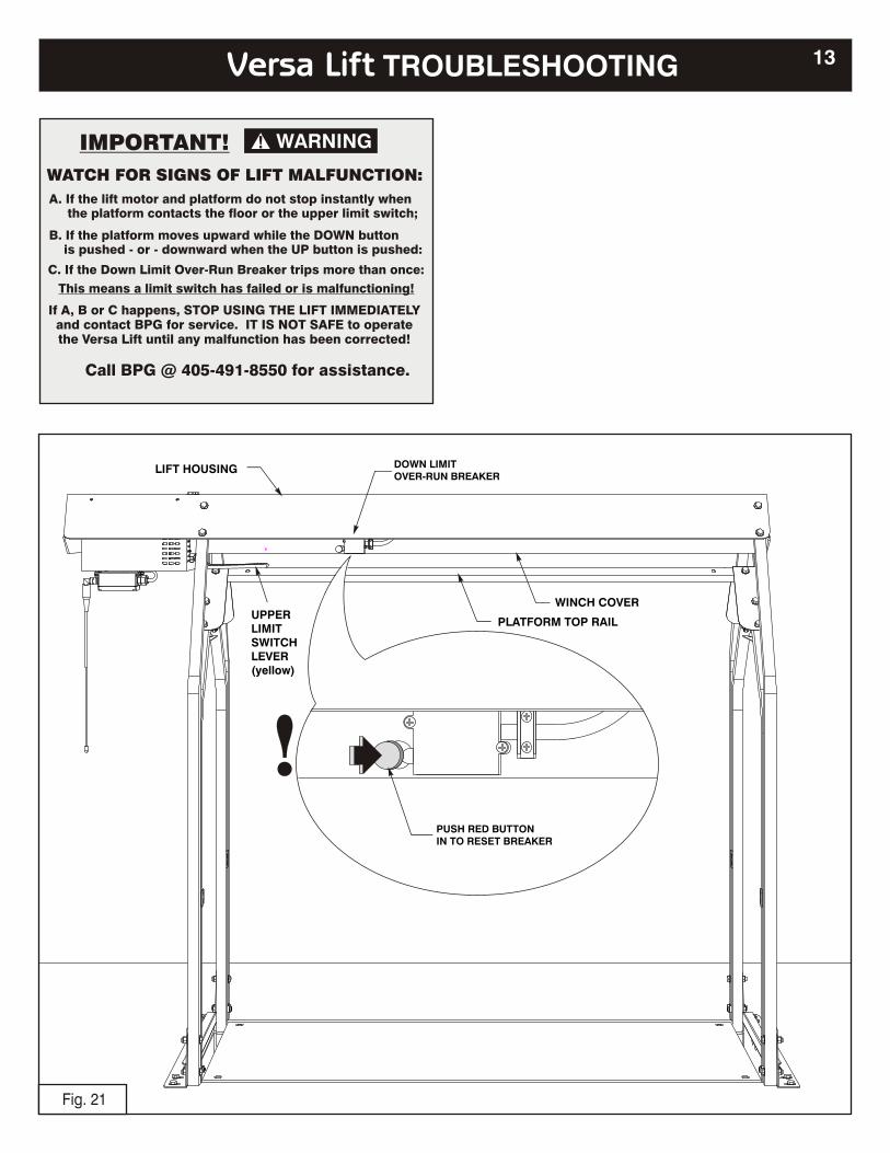
Fig. 21
PUSH RED BUTTONIN TO RESET BREAKER
DOWN LIMITOVER-RUN BREAKER
13Versa Lift TROUBLESHOOTING
LIFT HOUSING
WINCH COVER
PLATFORM TOP RAILUPPERLIMITSWITCHLEVER(yellow)
!
WARNING!
A. If the lift motor and platform do not stop instantly when the platform contacts the floor or the upper limit switch;
B. If the platform moves upward while the DOWN button is pushed - or - downward when the UP button is pushed:
This means a limit switch has failed or is malfunctioning!
If A, B or C happens, STOP USING THE LIFT IMMEDIATELY and contact BPG for service. IT IS NOT SAFE to operate the Versa Lift until any malfunction has been corrected!
Call BPG @ 405-491-8550 for assistance.
WATCH FOR SIGNS OF LIFT MALFUNCTION:
IMPORTANT!
C. If the Down Limit Over-Run Breaker trips more than once:
PAIRING TRANSMITTERSTO THE RECEIVER
� View inside receiver with cover removed
14 Versa Lift Transmitter & Receiver (Wireless Models)
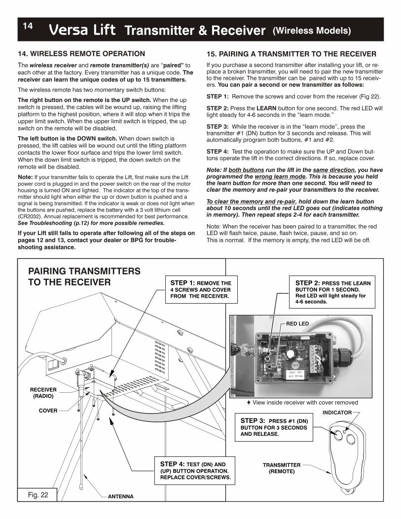
14. WIRELESS REMOTE OPERATION
The wireless receiver and remote transmitter(s) are “paired” to each other at the factory. Every transmitter has a unique code. The receiver can learn the unique codes of up to 15 transmitters.
The wireless remote has two momentary switch buttons:
The right button on the remote is the UP switch. When the up switch is pressed, the cables will be wound up, raising the lifting platform to the highest position, where it will stop when it trips the upper limit switch. When the upper limit switch is tripped, the up switch on the remote will be disabled.
The left button is the DOWN switch. When down switch is pressed, the lift cables will be wound out until the lifting platform contacts the lower floor surface and trips the lower limit switch. When the down limit switch is tripped, the down switch on the remote will be disabled.
Note: If your transmitter fails to operate the Lift, first make sure the Lift power cord is plugged in and the power switch on the rear of the motor housing is turned ON and lighted. The indicator at the top of the trans-mitter should light when either the up or down button is pushed and a signal is being transmitted. If the indicator is weak or does not light when the buttons are pushed, replace the battery with a 3 volt lithium cell (CR2032). Annual replacement is recommended for best performance. See Troubleshooting (p.12) for more possible remedies.
If your Lift still fails to operate after following all of the steps on pages 12 and 13, contact your dealer or BPG for trouble-shooting assistance.
RECEIVER(RADIO)
COVER
TRANSMITTER(REMOTE)
STEP 2: PRESS THE LEARN BUTTON FOR 1 SECOND. Red LED will light steady for 4-6 seconds.
STE P 3: PRESS #1 (DN)
BUTTON FOR 3 SECONDSAND RELEASE.
STE P 4: TEST (DN) AND
(UP) BUTTON OPERATION.REPLACE COVER/SCREWS.
STEP 1: REMOVE THE
4 SCREWS AND COVER FROM THE RECEIVER.
ANTENNAFig. 22
RED LED
INDICATOR
15. PAIRING A TRANSMITTER TO THE RECEIVER
If you purchase a second transmitter after installing your lift, or re-place a broken transmitter, you will need to pair the new transmitter to the receiver. The transmitter can be paired with up to 15 receiv-ers. You can pair a second or new transmitter as follows:
STEP 1: Remove the screws and cover from the receiver (Fig 22).
STEP 2: Press the LEARN button for one second. The red LED will light steady for 4-6 seconds in the “learn mode.”
STEP 3: While the receiver is in the “learn mode”, press the transmitter #1 (DN) button for 3 seconds and release. This will automatically program both buttons, #1 and #2.
STEP 4: Test the operation to make sure the UP and Down but-tons operate the lift in the correct directions. If so, replace cover.
Note: If both buttons run the lift in the same direction, you have programmed the wrong learn mode. This is because you held the learn button for more than one second. You will need to clear the memory and re-pair your transmitters to the receiver.
To clear the memory and re-pair, hold down the learn button about 10 seconds until the red LED goes out (indicates nothing in memory). Then repeat steps 2-4 for each transmitter.
Note: When the receiver has been paired to a transmitter, the red LED will flash twice, pause, flash twice, pause, and so on.This is normal. If the memory is empty, the red LED will be off.
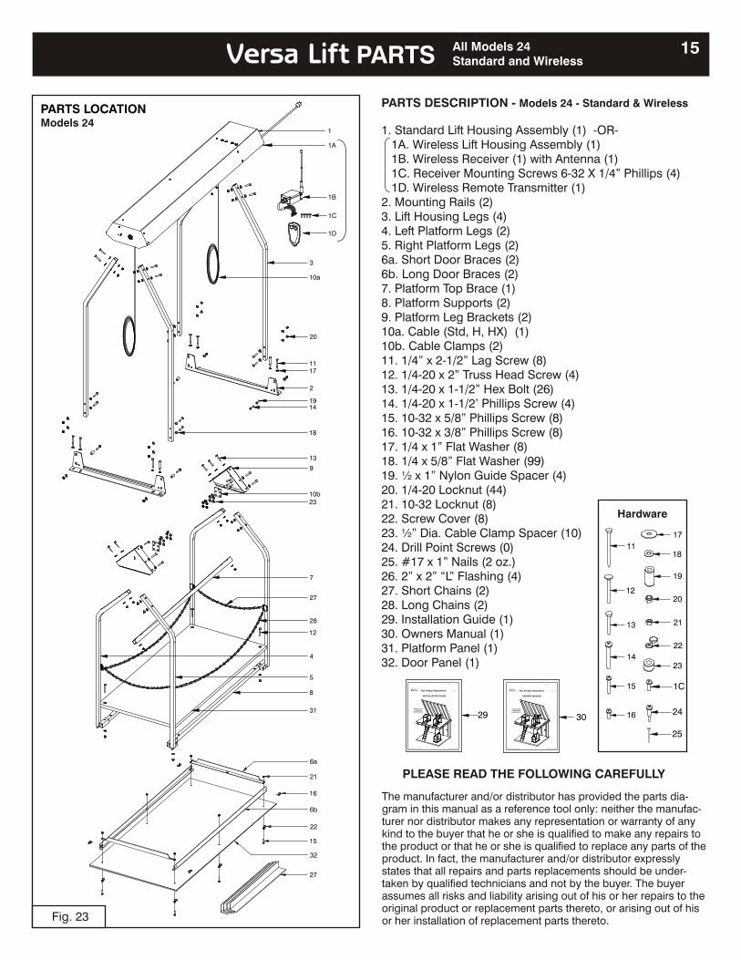
Fig. 23
PARTS LOCATIONModels 24
15Versa Lift PARTS
PLEASE READ THE FOLLOWING CAREFULLY
The manufacturer and/or distributor has provided the parts dia-gram in this manual as a reference tool only: neither the manufac-turer nor distributor makes any representation or warranty of any kind to the buyer that he or she is qualified to make any repairs to the product or that he or she is qualified to replace any parts of the product. In fact, the manufacturer and/or distributor expressly states that all repairs and parts replacements should be under-taken by qualified technicians and not by the buyer. The buyer assumes all risks and liability arising out of his or her repairs to the original product or replacement parts thereto, or arising out of his or her installation of replacement parts thereto.
All Models 24Standard and Wireless
1C
1
4
8
5
31
28
7
10b
27
12
2
11
14
17
19
20
13
10a
23
18
9
1B
1D
1A
3
1C
25
PARTS DESCRIPTION - Models 24 - Standard &
1. Standard Lift Housing Assembly (1) -OR- 1A. Wireless Lift Housing Assembly (1) 1B. Wireless Receiver (1) with Antenna (1) 1C. Receiver Mounting Screws 6-32 X 1/4” Phillips (4) 1D. Wireless Remote Transmitter (1)2. Mounting Rails (2)3. Lift Housing Legs (4)4. Left Platform Legs (2)5. Right Platform Legs (2)6a. Short Door Braces (2)6b. Long Door Braces (2)7. Platform Top Brace (1)8. Platform Supports (2)9. Platform Leg Brackets (2)10a. Cable (Std, H, HX) (1)10b. Cable Clamps (2)11. 1/4” x 2-1/2” Lag Screw (8)12. 1/4-20 x 2” Truss Head Screw (4)13. 1/4-20 x 1-1/2” Hex Bolt (26)14. 1/4-20 x 1-1/2’ Phillips Screw (4)15. 10-32 x 5/8” Phillips Screw (8)16. 10-32 x 3/8” Phillips Screw (8)17. 1/4 x 1” Flat Washer (8)18. 1/4 x 5/8” Flat Washer (99)19. ½ x 1” Nylon Guide Spacer (4)20. 1/4-20 Locknut (44)21. 10-32 Locknut (8)22. Screw Cover (8)23. ½” Dia. Cable Clamp Spacer (10)24. Drill Point Screws (0)25. #17 x 1” Nails (2 oz.)26. 2” x 2” “L” Flashing (4)27. Short Chains (2)28. Long Chains (2)29. Installation Guide (1)30. Owners Manual (1)31. Platform Panel (1)32. Door Panel (1)
Wireless
Attic Storage Lifting SystemAttic Storage Lifting System
Versa Lift
===
TM
Byers Products Group
BPG
Model 24HModel 24
SAFETY GUIDEOPERATION
MAINTENANCE
OWNERS MANUAL
US & Foreign Patents Pending Copyright © 2006 BPG
Attic Storage Lifting SystemAttic Storage Lifting System
Versa Lift
===
TM
Byers Products Group
BPG
Model 24HModel 24
SAFETY GUIDEOPERATION
MAINTENANCE
INSTALLATION GUIDE
US & Foreign Patents Pending Copyright © 2006 BPG
3029 16
15
14
13
12
11
22
21
20
19
23
18
17
Hardware
24
22
15
32
21
16
27
6a
6b

SAVE YOUR LIFT HEAD SHIPPING BOXES.YOU MAY NEED THEM FOR WARRANTY REPAIRS!
!! IMPORTANT NOTICE !!If you do not register, we cannot notify you about
product recall notices, safety bulletins, etc!
Versa Lift Information
Model No._________________________________
Serial No._________________________________
Installation Date: __________________________
Purchased From: __________________________
Installed By: ______________________________
Warranty Registration Date: ________________
Please Activate Your Warranty:
Register Online at (click on the warranty tab at the bottom of the home page)
www.bpghome.com
- OR -
Mail in your completed warranty card.(provided with this manual pack)
For Future Reference Record the Following Information:
-END OF OWNERS MANUAL-Please turn this
booklet over to read the
INSTALLATION GUIDE
Byers Products Group "Innovations for your home"
9641 NW 6th StreetOkla City, OK 73127
Ph: 405-491-8550www.bpghome.com