Embed Size (px)
Citation preview
Attachment of Residential Deck Ledger to Metal Plate Connected Wood Truss
Floor Systems
Overview
Revised 9/2/2016
SBCA has been the voice of the structural building
components industry since 1983, providing educational
programs and technical information, disseminating industry
news, and facilitating networking opportunities for
manufacturers of roof trusses, wall panels and floor trusses.
SBCA endeavors to expand component manufacturers’
market share and enhance the professionalism of the
component manufacturing industry.
Copyright © 2016 Structural Building Components Association.
Introduction
• This presentation provides construction details for residential deck ledger attachment to metal plate connected wood truss floor systems.
• Installation instructions are also included
• The applicable codes and standards follow the 2009, 2012, and 2015 International Building Code (IBC) and International Residential Code (IRC).
Introduction
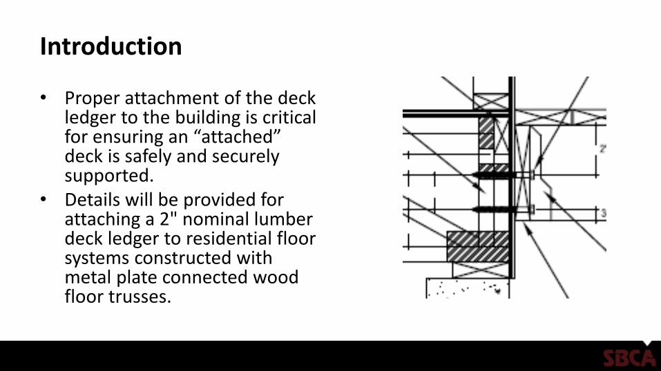
• Proper attachment of the deck ledger to the building is critical for ensuring an “attached” deck is safely and securely supported.
• Details will be provided for attaching a 2" nominal lumber deck ledger to residential floor systems constructed with metal plate connected wood floor trusses.
Key Definitions
• Deck Ledger – A horizontal lumber beam attached to an existing wall and used to tie in construction elements such as porch roofs and decks. A deck ledger is installed as part of the deck frame construction and supports one end of the deck joists.
• Truss – An engineered structural component, assembled from wood members, metal connector plates and other mechanical fasteners, designed to carry its own weight and superimposed design loads. The truss members form a semi-rigid structural framework and are assembled such that the members form triangles.
• Wood Structural Panel (WSP) – A panel manufactured from wood veneers, strands or wafers or a combination of veneer and wood strands or wafers bonded together with waterproof synthetic resins or other suitable bonding systems. Examples include: plywood, Oriented Strand Board (OSB), waferboard and composite panels.
Background
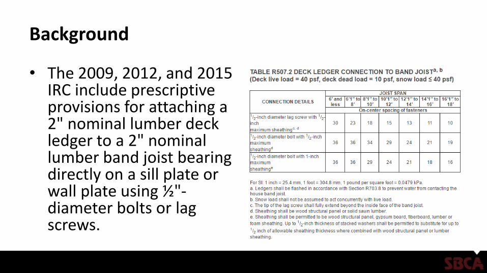
• The 2009, 2012, and 2015 IRC include prescriptive provisions for attaching a 2" nominal lumber deck ledger to a 2" nominal lumber band joist bearing directly on a sill plate or wall plate using ½"-diameter bolts or lag screws.
Background
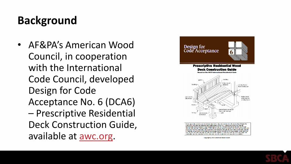
• AF&PA’s American Wood Council, in cooperation with the International Code Council, developed Design for Code Acceptance No. 6 (DCA6) – Prescriptive Residential Deck Construction Guide, available at awc.org.
Background
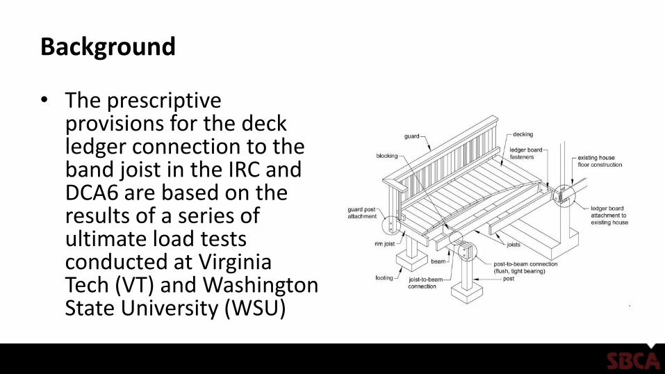
• The prescriptive provisions for the deck ledger connection to the band joist in the IRC and DCA6 are based on the results of a series of ultimate load tests conducted at Virginia Tech (VT) and Washington State University (WSU)
Background
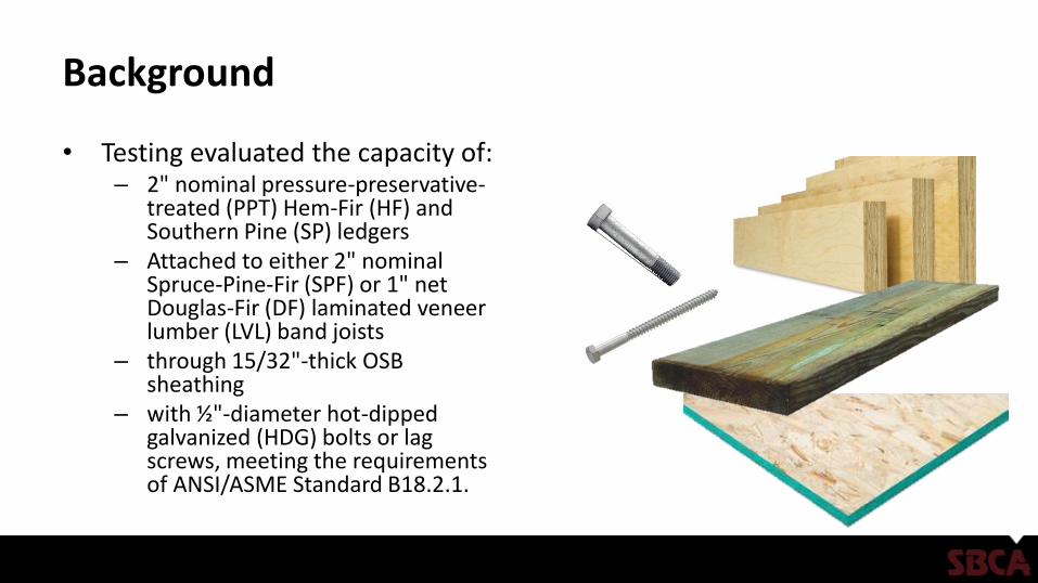
• Testing evaluated the capacity of:– 2" nominal pressure-preservative-
treated (PPT) Hem-Fir (HF) and Southern Pine (SP) ledgers
– Attached to either 2" nominal Spruce-Pine-Fir (SPF) or 1" net Douglas-Fir (DF) laminated veneer lumber (LVL) band joists
– through 15/32"-thick OSB sheathing
– with ½"-diameter hot-dipped galvanized (HDG) bolts or lag screws, meeting the requirements of ANSI/ASME Standard B18.2.1.
Background
• Deck ledger assemblies evaluated at VT and WSU were deemed to represent commonly accepted means of connecting deck ledgers to band joints that cannot be evaluated using the provisions of the National Design Specification for Wood Construction (NDS) because:– Ledger is not in direct contact with the band joist (i.e., separated by
15/32" OSB sheathing).
– Minimum required penetration depth of four diameters (4D) is not met when using ½"-diameter lag screws into an 11/2"-thick band joist.
Application
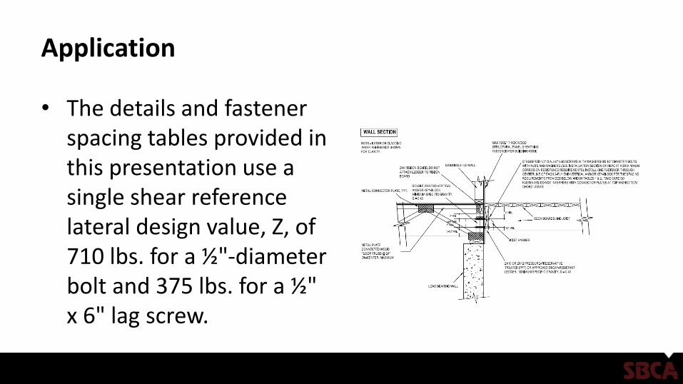
• The details and fastener spacing tables provided in this presentation use a single shear reference lateral design value, Z, of 710 lbs. for a ½"-diameter bolt and 375 lbs. for a ½" x 6" lag screw.
Application
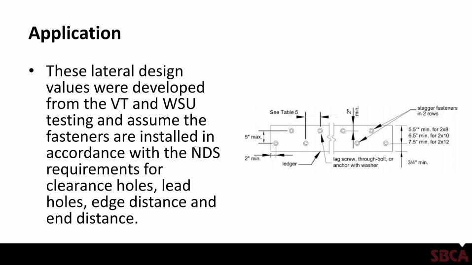
• These lateral design values were developed from the VT and WSU testing and assume the fasteners are installed in accordance with the NDS requirements for clearance holes, lead holes, edge distance and end distance.
Application
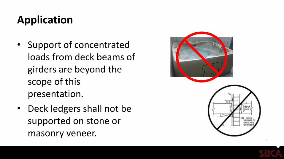
• Support of concentrated loads from deck beams of girders are beyond the scope of this presentation.
• Deck ledgers shall not be supported on stone or masonry veneer.
Findings
• Nailing deck ledgers to metal plate connected wood truss floor systems is not sufficient.
• The deck ledger must be attached to the truss or key-block with lag screws or bolts.
• The options and connection details for connecting a deck ledger to the metal plate connected wood truss floor system provided in this presentation are sufficient, however, and may be referred to by the building designer to achieve a code-conforming deck ledger connection.
References
• Anderson, C.A., Woeste, F.E. and Loferski, J.R. 2003; Manual for the Inspection of Residential Wood Decks and Balconies; Forest Products Society, 2801 Marshall Ct., Madison, WI 53705.
• ANSI/AWC NDS-2012, ASD/LRFD NDS; National Design Specification for Wood Construction. 2012; American Wood Council, 222 Catoctin Circle, SE, Suite 201, Leesburg, VA 20175.
• Carradine, D.M., Bender, D., Loferski, J.R. and Woeste, F.E. 2005; Residential Deck Ledger Design; Building Safety Journal, December, 2005: (4-7).
• Carradine, D.M., Bender, D., Loferski, J.R. and Woeste, F.E. 2006; Residential Deck Ledger Connection Testing and Design; Structure Magazine, May, 2008: (53-56).
• Design for Code Acceptance, DCA 6, Prescriptive Residential Wood Deck Construction Guide; 2009; American Wood Council, 222 Catoctin Circle, SE, Suite 201, Leesburg, VA 20175.
• Loferski, J.R., Woeste, F.E., Caudill, R., Platt, T. and Smith, Q. 2004; Load-Tested Deck Ledger Connections; Journal of Light Construction. 22(6):71-78.
• Woeste, F.E. 2008; Safe and Durable Coastal Decks; Coastal Contractor, March/April, 2008: (1-7).

Attachment of Residential Deck Ledger to Side of Metal Plate
Connected Wood Truss Floor Ladder
Installation Instructions
Revised 9/2/2016

SBCA has been the voice of the structural building
components industry since 1983, providing educational
programs and technical information, disseminating industry
news, and facilitating networking opportunities for
manufacturers of roof trusses, wall panels and floor trusses.
SBCA endeavors to expand component manufacturers’
market share and enhance the professionalism of the
component manufacturing industry.
Copyright © 2016 Structural Building Components Association.
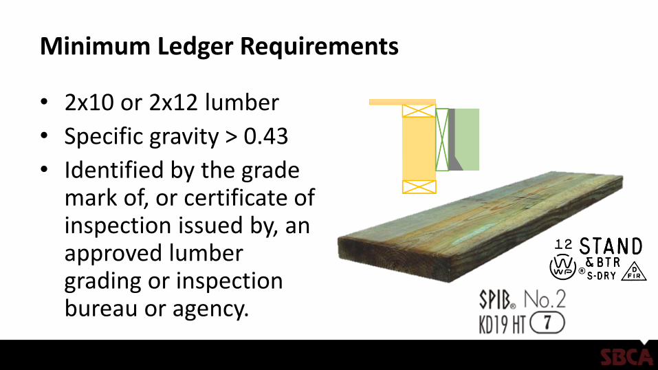
Minimum Ledger Requirements
• 2x10 or 2x12 lumber
• Specific gravity > 0.43
• Identified by the grade mark of, or certificate of inspection issued by, an approved lumber grading or inspection bureau or agency.
Minimum Ledger Requirements
• Made of PPT (Preservative Pressure Treated) or code approved decay-resistant lumber
• Pressure treatment must be an approved process in accordance with American Wood Protection Association standards.
Step 1: Review Connection Details
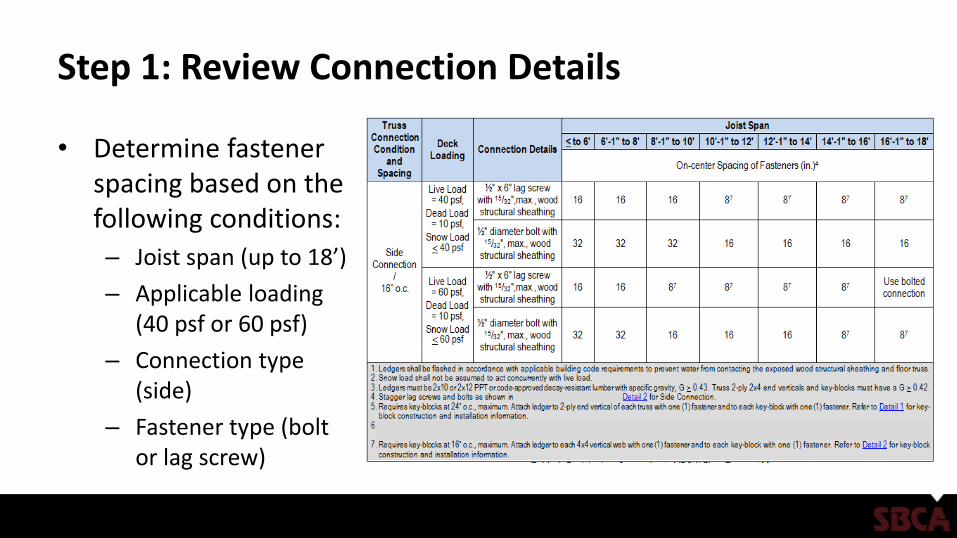
• Determine fastener spacing based on the following conditions:
– Joist span (up to 18’)
– Applicable loading (40 psf or 60 psf)
– Connection type (side)
– Fastener type (bolt or lag screw)
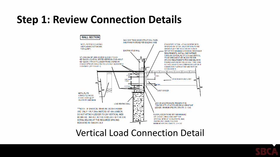
Step 1: Review Connection Details
Vertical Load Connection Detail
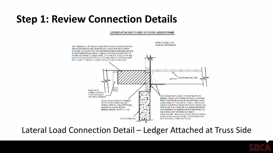
Step 1: Review Connection Details
Lateral Load Connection Detail – Ledger Attached at Truss Side

Step 2: Install Over Structural Sheathing
• Install ledger directly over wood structural sheathing fastened to the wall per IRC Chapter 6.
• Maximum thickness of sheathing is 15/32"

Step 2: Install Over Structural Sheathing
• Attach ledger through wood structural sheathing into one of the following: – 2-ply 2x4 truss end
vertical
– 4x4 vertical web
– Key-block
Step 2: Install Over Structural Sheathing
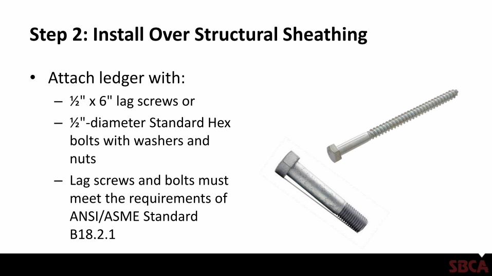
• Attach ledger with:
– ½" x 6" lag screws or
– ½"-diameter Standard Hex bolts with washers and nuts
– Lag screws and bolts must meet the requirements of ANSI/ASME Standard B18.2.1
Step 2: Install Over Structural Sheathing
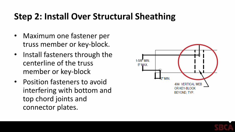
• Maximum one fastener per truss member or key-block.
• Install fasteners through the centerline of the truss member or key-block
• Position fasteners to avoid interfering with bottom and top chord joints and connector plates.
Step 3: Fastener Specification
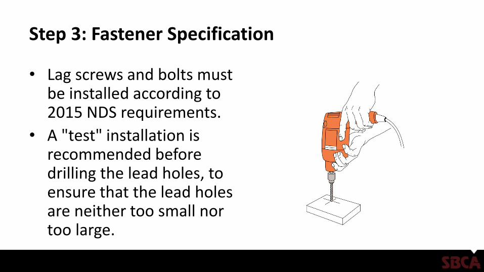
• Lag screws and bolts must be installed according to 2015 NDS requirements.
• A "test" installation is recommended before drilling the lead holes, to ensure that the lead holes are neither too small nor too large.

Step 3: Fastener Specification
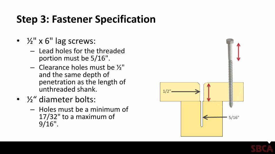
• ½" x 6" lag screws:– Lead holes for the threaded
portion must be 5/16". – Clearance holes must be ½"
and the same depth of penetration as the length of unthreaded shank.
• ½“ diameter bolts:– Holes must be a minimum of
17/32" to a maximum of 9/16".

Step 3: Fastener Specification
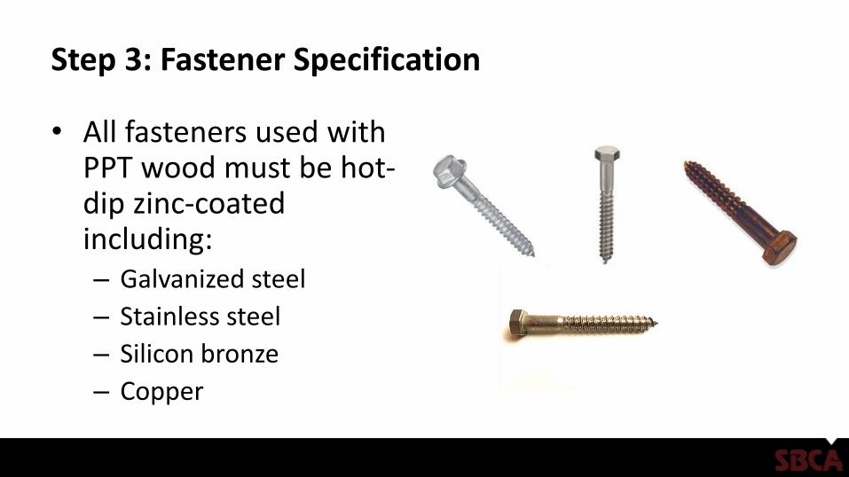
• All fasteners used with PPT wood must be hot-dip zinc-coated including:– Galvanized steel
– Stainless steel
– Silicon bronze
– Copper

Step 3: Fastener Specification
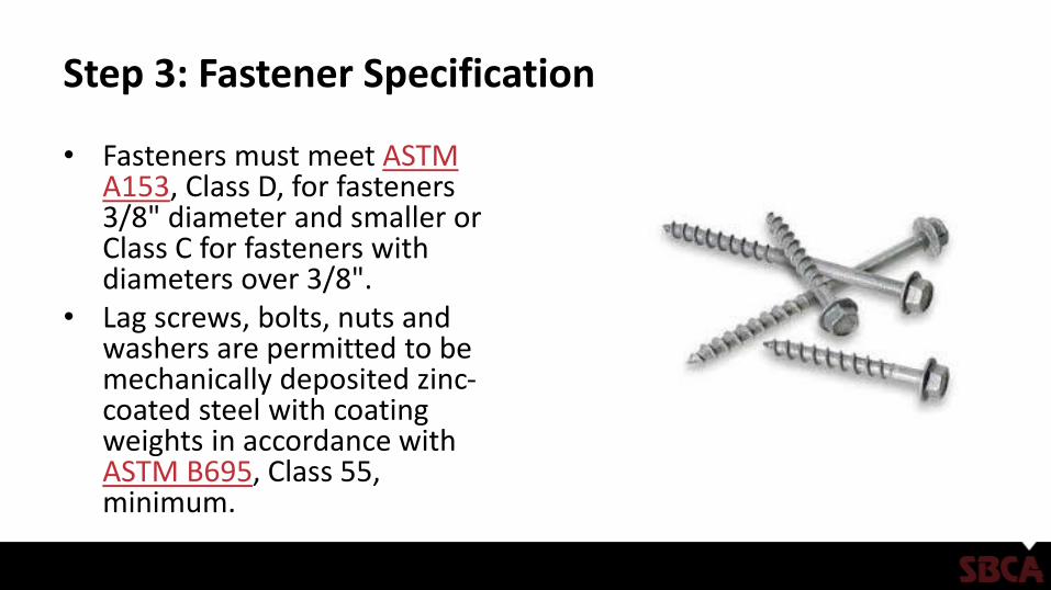
• Fasteners must meet ASTM A153, Class D, for fasteners 3/8" diameter and smaller or Class C for fasteners with diameters over 3/8".
• Lag screws, bolts, nuts and washers are permitted to be mechanically deposited zinc-coated steel with coating weights in accordance with ASTM B695, Class 55, minimum.
Step 4: Hardware Specification
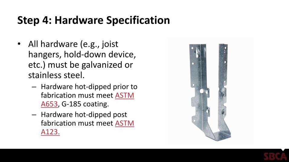
• All hardware (e.g., joist hangers, hold-down device, etc.) must be galvanized or stainless steel.– Hardware hot-dipped prior to
fabrication must meet ASTM A653, G-185 coating.
– Hardware hot-dipped post fabrication must meet ASTM A123.
Step 4: Hardware Specification
• Additional requirements include: – Fasteners and hardware exposed to saltwater or located within 300' of
a saltwater shoreline must be stainless steel grade 304 or 316.
– Fasteners and hardware must be of the same corrosion-resistant material.
– Other coated or non-ferrous fasteners or hardware must be approved by the authority having jurisdiction.

Step 5: Flashing Installation
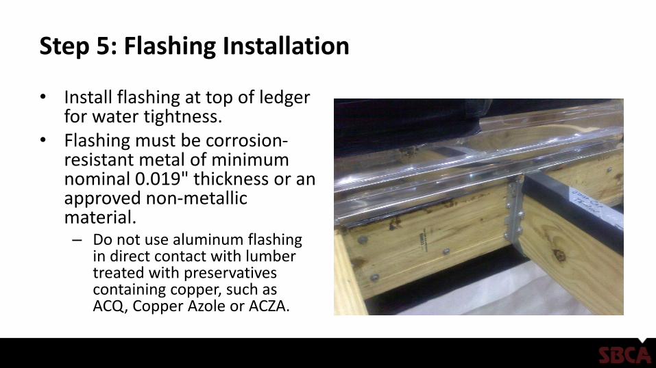
• Install flashing at top of ledger for water tightness.
• Flashing must be corrosion-resistant metal of minimum nominal 0.019" thickness or an approved non-metallic material. – Do not use aluminum flashing
in direct contact with lumber treated with preservatives containing copper, such as ACQ, Copper Azole or ACZA.
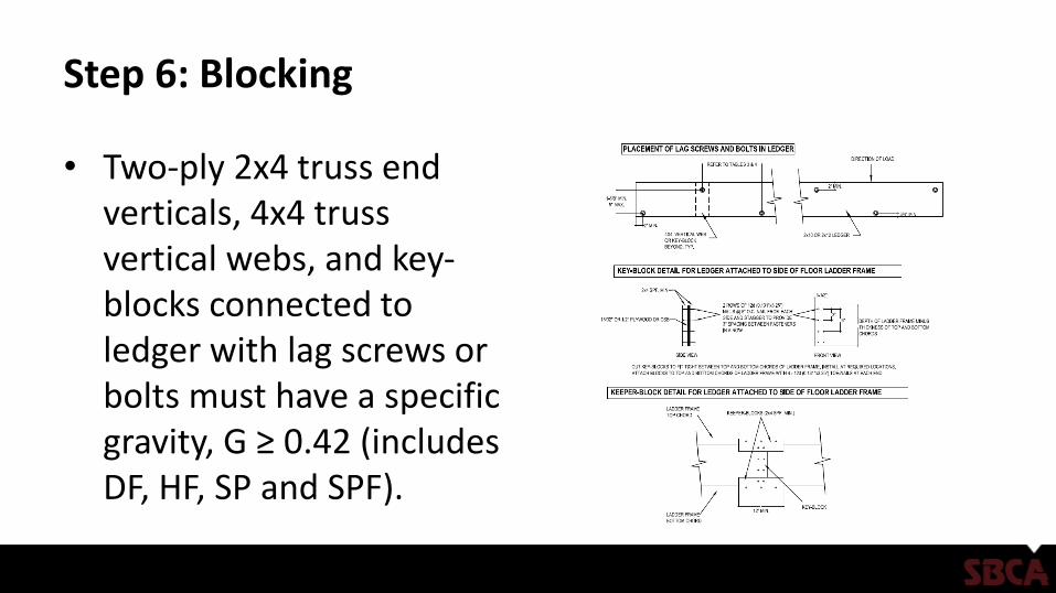
Step 6: Blocking
• Two-ply 2x4 truss end verticals, 4x4 truss vertical webs, and key-blocks connected to ledger with lag screws or bolts must have a specific gravity, G ≥ 0.42 (includes DF, HF, SP and SPF).
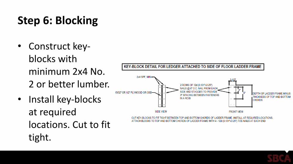
Step 6: Blocking
• Construct key-blocks with minimum 2x4 No. 2 or better lumber.
• Install key-blocks at required locations. Cut to fit tight.
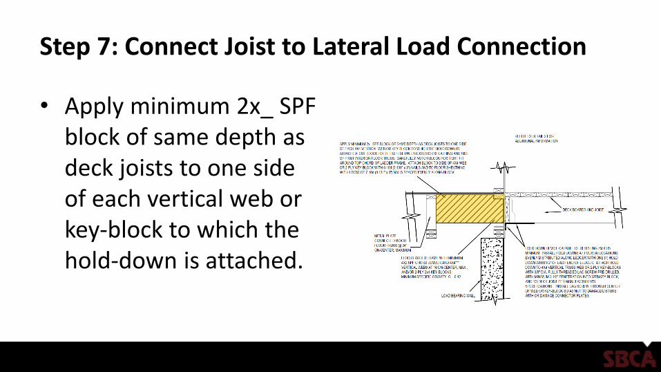
Step 7: Connect Joist to Lateral Load Connection
• Apply minimum 2x_ SPF block of same depth as deck joists to one side of each vertical web or key-block to which the hold-down is attached.
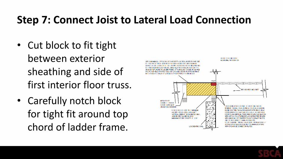
Step 7: Connect Joist to Lateral Load Connection
• Cut block to fit tight between exterior sheathing and side of first interior floor truss.
• Carefully notch block for tight fit around top chord of ladder frame.
Step 7: Connect Joist to Lateral Load Connection
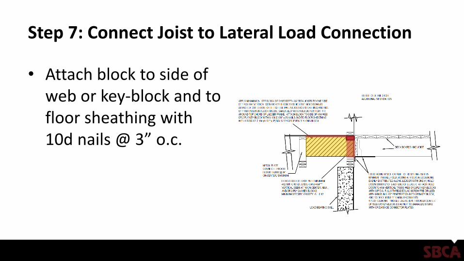
• Attach block to side of web or key-block and to floor sheathing with 10d nails @ 3” o.c.
Step 7: Connect Joist to Lateral Load Connection
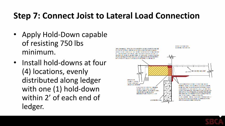
• Apply Hold-Down capable of resisting 750 lbsminimum.
• Install hold-downs at four (4) locations, evenly distributed along ledger with one (1) hold-down within 2’ of each end of ledger.
Step 7: Connect Joist to Lateral Load Connection
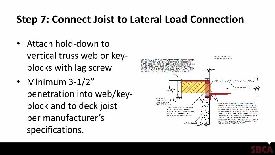
• Attach hold-down to vertical truss web or key-blocks with lag screw
• Minimum 3-1/2” penetration into web/key-block and to deck joist per manufacturer’s specifications.
Step 7: Connect Joist to Lateral Load Connection
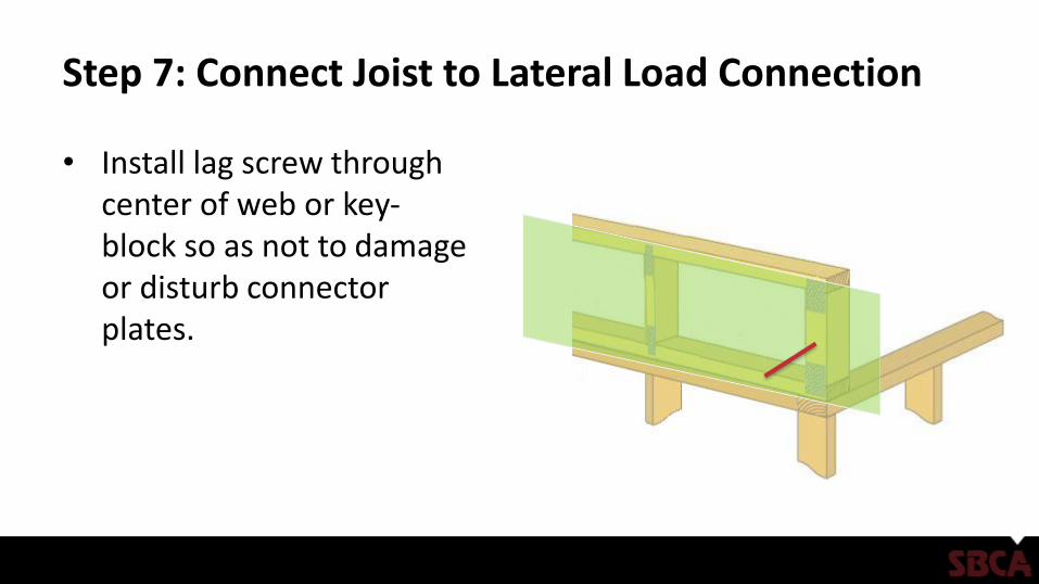
• Install lag screw through center of web or key-block so as not to damage or disturb connector plates.

References
• SRR 1408-01 - Attachment of Residential Deck Ledger to Metal Plate Connected Wood Truss Floor Systems
Attachment of Residential Deck Ledger to End of Metal Plate
Connected Wood Truss Floor Systems
Installation Instructions
Revised 9/2/2016

SBCA has been the voice of the structural building
components industry since 1983, providing educational
programs and technical information, disseminating industry
news, and facilitating networking opportunities for
manufacturers of roof trusses, wall panels and floor trusses.
SBCA endeavors to expand component manufacturers’
market share and enhance the professionalism of the
component manufacturing industry.
Copyright © 2016 Structural Building Components Association.
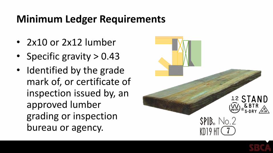
Minimum Ledger Requirements
• 2x10 or 2x12 lumber
• Specific gravity > 0.43
• Identified by the grade mark of, or certificate of inspection issued by, an approved lumber grading or inspection bureau or agency.

Minimum Ledger Requirements
• Made of PPT (Preservative Pressure Treated) or code approved decay-resistant lumber
• Pressure treatment must be an approved process in accordance with American Wood Protection Association standards.
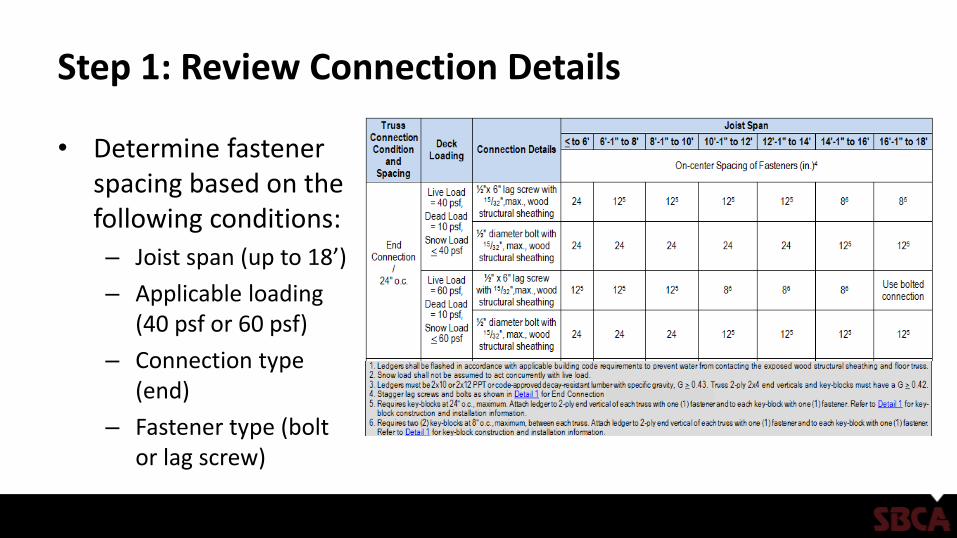
Step 1: Review Connection Details
• Determine fastener spacing based on the following conditions:
– Joist span (up to 18’)
– Applicable loading (40 psf or 60 psf)
– Connection type (end)
– Fastener type (bolt or lag screw)
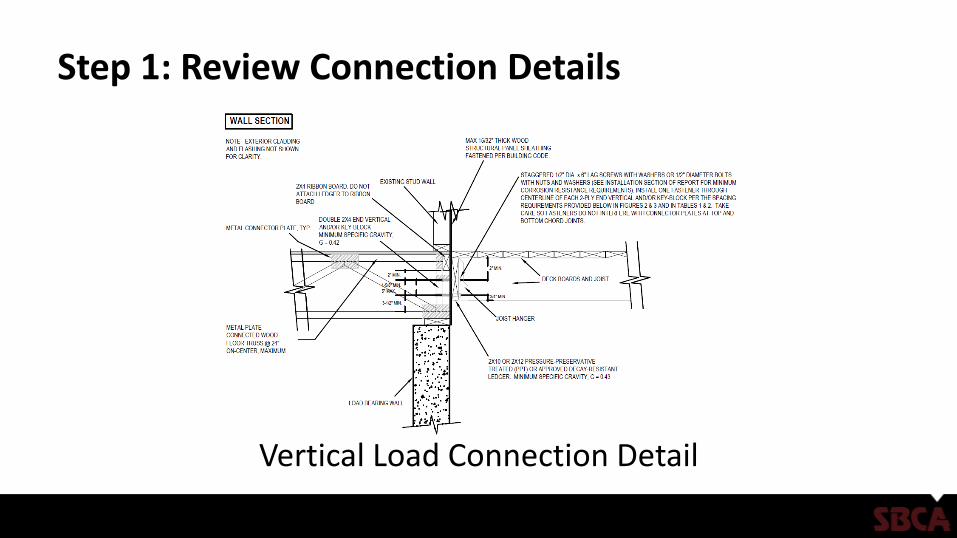
Step 1: Review Connection Details
Vertical Load Connection Detail
Step 1: Review Connection Details
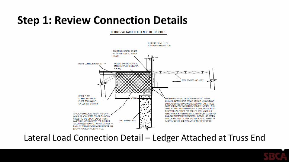
Lateral Load Connection Detail – Ledger Attached at Truss End
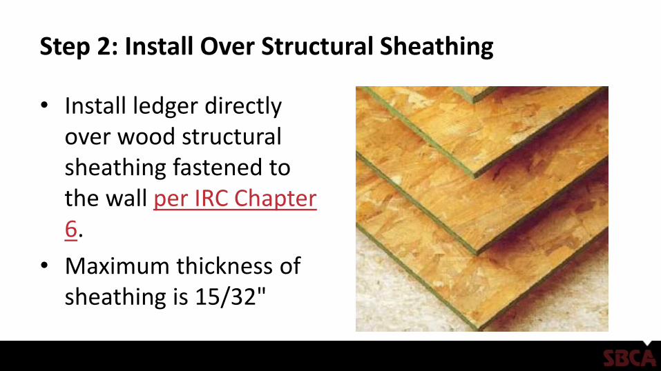
Step 2: Install Over Structural Sheathing
• Install ledger directly over wood structural sheathing fastened to the wall per IRC Chapter 6.
• Maximum thickness of sheathing is 15/32"
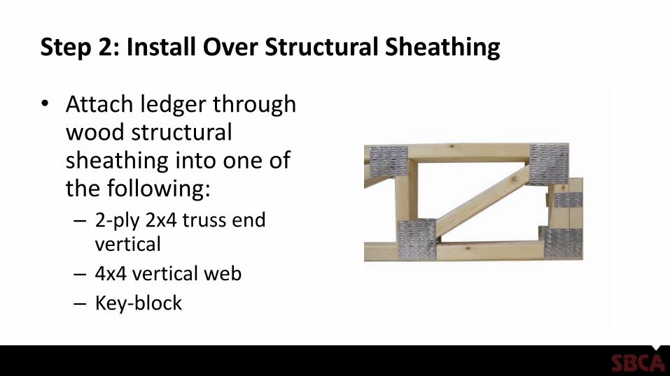
Step 2: Install Over Structural Sheathing
• Attach ledger through wood structural sheathing into one of the following: – 2-ply 2x4 truss end
vertical
– 4x4 vertical web
– Key-block
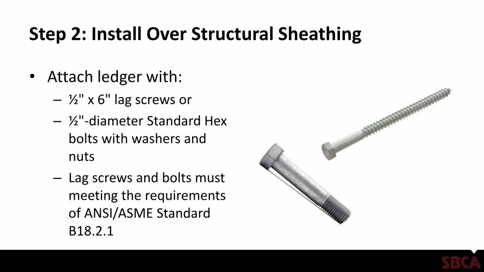
Step 2: Install Over Structural Sheathing
• Attach ledger with:
– ½" x 6" lag screws or
– ½"-diameter Standard Hex bolts with washers and nuts
– Lag screws and bolts must meeting the requirements of ANSI/ASME Standard B18.2.1

Step 2: Install Over Structural Sheathing
• Maximum one fastener per truss member or key-block.
• Install fasteners through the centerline of the truss member or key-block
• Position fasteners to avoid interfering with bottom and top chord joints and connector plates.

Step 3: Fastener Specification
• Lag screws and bolts must be installed according to 2015 NDS requirements.
• A "test" installation is recommended before drilling the lead holes, to ensure that the lead holes are neither too small nor too large.
• ½" x 6" lag screws:– Lead holes for the threaded
portion must be 5/16". – Clearance holes must be ½"
and the same depth of penetration as the length of unthreaded shank.
• ½“ diameter bolts:– Holes must be a minimum of
17/32" to a maximum of 9/16".
Step 3: Fastener Specification
Step 3: Fastener Specification
• All fasteners used with PPT wood must be hot-dip zinc-coated including:– Galvanized steel
– Stainless steel
– Silicon bronze
– Copper
Step 3: Fastener Specification
• Fasteners must meet ASTM A153, Class D, for fasteners 3/8" diameter and smaller or Class C for fasteners with diameters over 3/8".
• Lag screws, bolts, nuts and washers are permitted to be mechanically deposited zinc-coated steel with coating weights in accordance with ASTM B695, Class 55, minimum.

Step 4: Hardware Specification
• All hardware (e.g., joist hangers, hold-down device, etc.) must be galvanized or stainless steel.– Hardware hot-dipped prior to
fabrication must meet ASTM A653, G-185 coating.
– Hardware hot-dipped post fabrication must meet ASTM A123.

Step 4: Hardware Specification
• Additional requirements include: – Fasteners and hardware exposed to saltwater or located within 300' of
a saltwater shoreline must be stainless steel grade 304 or 316.
– Fasteners and hardware must be of the same corrosion-resistant material.
– Other coated or non-ferrous fasteners or hardware must be approved by the authority having jurisdiction.
Step 5: Flashing Installation
• Install flashing at top of ledger for water tightness.
• Flashing must be corrosion-resistant metal of minimum nominal 0.019" thickness or an approved non-metallic material. – Do not use aluminum flashing
in direct contact with lumber treated with preservatives containing copper, such as ACQ, Copper Azole or ACZA.
Step 6: Blocking
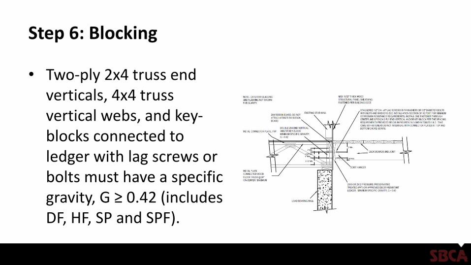
• Two-ply 2x4 truss end verticals, 4x4 truss vertical webs, and key-blocks connected to ledger with lag screws or bolts must have a specific gravity, G ≥ 0.42 (includes DF, HF, SP and SPF).
Step 6: Blocking
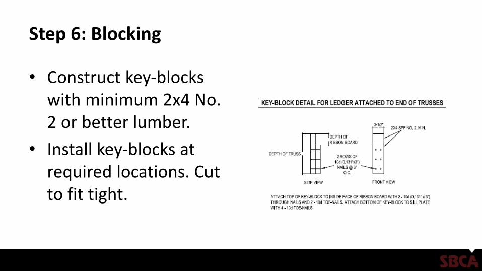
• Construct key-blocks with minimum 2x4 No. 2 or better lumber.
• Install key-blocks at required locations. Cut to fit tight.
Step 7: Connect Joist to Lateral Load Connection
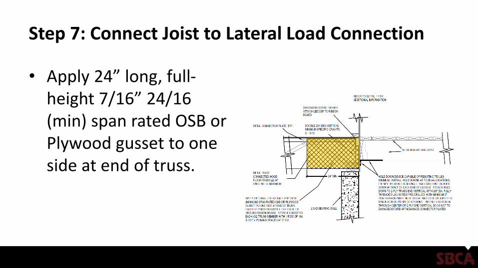
• Apply 24” long, full-height 7/16” 24/16 (min) span rated OSB or Plywood gusset to one side at end of truss.
Step 7: Connect Joist to Lateral Load Connection
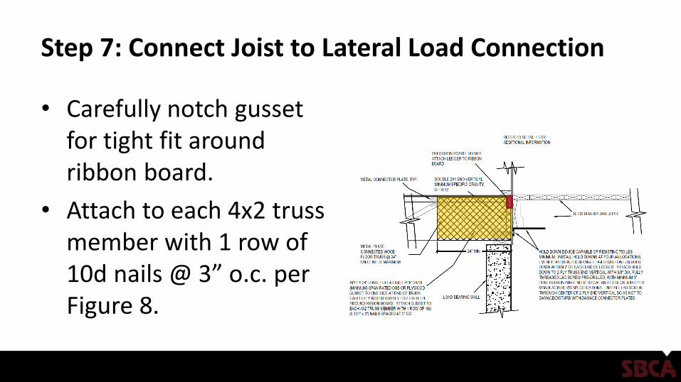
• Carefully notch gusset for tight fit around ribbon board.
• Attach to each 4x2 truss member with 1 row of 10d nails @ 3” o.c. per Figure 8.
Step 7: Connect Joist to Lateral Load Connection
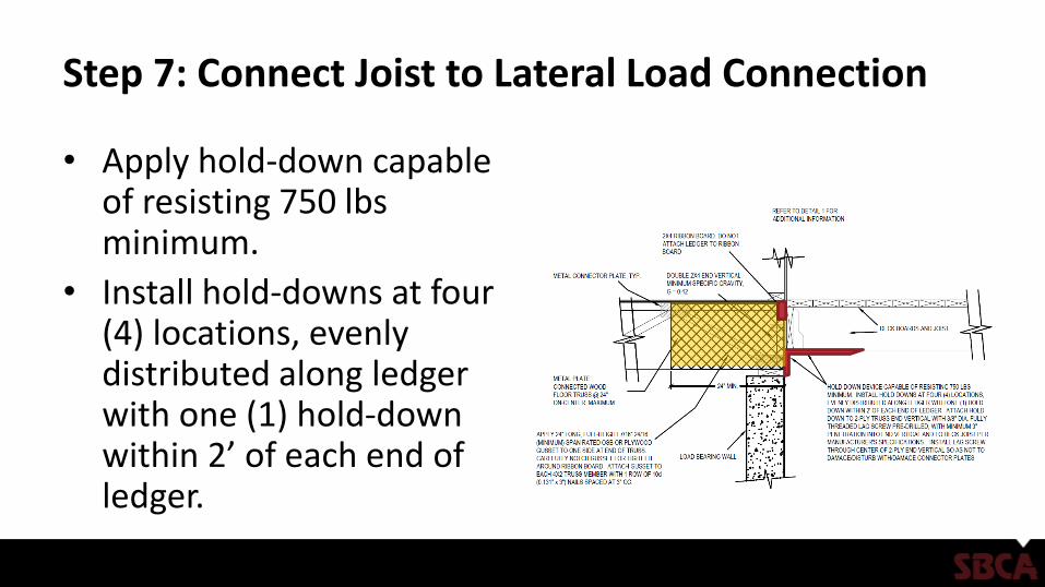
• Apply hold-down capable of resisting 750 lbsminimum.
• Install hold-downs at four (4) locations, evenly distributed along ledger with one (1) hold-down within 2’ of each end of ledger.
Step 7: Connect Joist to Lateral Load Connection
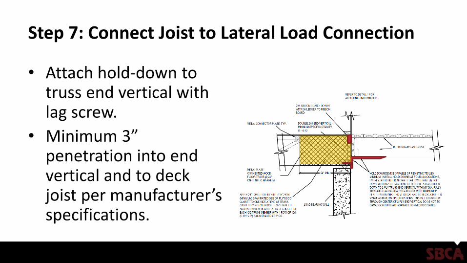
• Attach hold-down to truss end vertical with lag screw.
• Minimum 3” penetration into end vertical and to deck joist per manufacturer’s specifications.
Step 7: Connect Joist to Lateral Load Connection
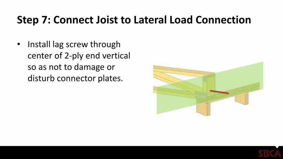
• Install lag screw through center of 2-ply end vertical so as not to damage or disturb connector plates.
References
• SRR 1408-01 - Attachment of Residential Deck Ledger to Metal Plate Connected Wood Truss Floor Systems