Embed Size (px)
Citation preview
ATTACHMENT A1
CONTAINER STORAGE

Waste Isolation Pilot Plant Hazardous Waste Permit October 2013
(This page intentionally blank)
Waste Isolation Pilot Plant Hazardous Waste Permit
October 2013
PERMIT ATTACHMENT A1 Page A1-i
ATTACHMENT A1
CONTAINER STORAGE
TABLE OF CONTENTS
Introduction ................................................................................................................................. 1
A1-1 Container Storage ........................................................................................................... 1 A1-1a Containers with Liquid .......................................................................................... 1 A1-1b Description of Containers ..................................................................................... 1
A1-1b(1) CH TRU Mixed Waste Containers ...................................................... 1 A1-1b(2) RH TRU Mixed Waste Containers ...................................................... 3 A1-1b(3) Container Compatibility ....................................................................... 4
A1-1c Description of the Container Storage Units .......................................................... 4 A1-1c(1) Waste Handling Building Container Storage Unit (WHB Unit) ............. 4 A1-1c(2) Parking Area Container Storage Unit (Parking Area Unit) ................. 13
A1-1d Container Management Practices ...................................................................... 14 A1-1d(1) Derived Waste .................................................................................. 15 A1-1d(2) CH TRU Mixed Waste Handling ....................................................... 16 A1-1d(3) RH TRU Mixed Waste Handling ....................................................... 19 A1-1d(4) Handling Waste in Shielded Containers ............................................ 22
A1-1e Inspections......................................................................................................... 23 A1-1e(1) WHB Unit .......................................................................................... 23 A1-1e(2) Parking Area Unit ............................................................................. 24
A1-1f Containment ...................................................................................................... 25 A1-1f(1) Secondary Containment Requirements for the WHB Unit ................. 26 A1-1f(2) Secondary Containment Description ................................................. 27
A1-1g Special Requirements for Ignitable, Reactive, and Incompatible Waste ............. 28 A1-1h Closure .............................................................................................................. 28 A1-1i Control of Run On .............................................................................................. 28
References ............................................................................................................................... 29
Waste Isolation Pilot Plant Hazardous Waste Permit October 2013
PERMIT ATTACHMENT A1 Page A1-ii
LIST OF TABLES
Table Title
Table A1-1 Basic Design Requirements, Principal Codes, and Standards Table A1-2 Waste Handling Equipment Capacities Table A1-3 RH TRU Mixed Waste Handling Equipment Capacities
LIST OF FIGURES
Figure Title
Figure A1-1 Waste Handling Building - CH TRU Mixed Waste Container Storage and Surge Areas
Figure A1-1a Waste Handling Building Plan (Ground Floor) Figure A1-1b Waste Handling Building Plan (Room 108 Detail) Figure A1-2 Parking Area - Container Storage and Surge Areas Figure A1-3 Standard 55-Gallon Drum (Typical) Figure A1-4 Standard Waste Box Figure A1-5 Ten-Drum Overpack Figure A1-6 85-Gallon Drum Figure A1-8a TRUPACT-II Shipping Container for CH Transuranic Mixed Waste (Schematic) Figure A1-8b Typical HalfPACT Shipping Container for CH Transuranic Mixed Waste
(Schematic) Figure A1-10 Facility Pallet for Seven-Pack of Drums Figure A1-10a Typical Containment Pallet Figure A1-11 Facility Transfer Vehicle, Facility Pallet, and Typical Pallet Stand Figure A1-12 TRUPACT-II Containers on Trailer Figure A1-13 WIPP Facility Surface and Underground CH Transuranic Mixed Waste Process
Flow Diagram Figure A1-14a RH Bay Ground Floor Figure A1-15 100-Gallon Drum Figure A1-16 Facility Canister Assembly Figure A1-16a RH-TRU 72-B Canister Assembly Figure A1-17a RH Bay, Cask Unloading Room, Hot Cell, Facility Cask Loading Room Figure A1-17b RH Hot Cell Storage Area Figure A1-17c RH Canister Transfer Cell Storage Area Figure A1-17d RH Facility Cask Loading Room Storage Area Figure A1-18 RH-TRU 72-B Shipping Cask on Trailer Figure A1-19 CNS 10-160B Shipping Cask on Trailer Figure A1-20 RH-TRU 72-B Shipping Cask for RH Transuranic Waste (Schematic) Figure A1-21 CNS 10-160B Shipping Cask for RH Transuranic Waste (Schematic) Figure A1-22a RH-TRU 72-B Cask Transfer Car Figure A1-22b CNS 10-160B Cask Transfer Car Figure A1-23 RH Transuranic Waste Facility Cask Figure A1-24 RH Facility Cask Transfer Car (Side View) Figure A1-25 CNS 10-160B Drum Carriage Figure A1-26 Surface and Underground RH Transuranic Mixed Waste Process Flow Diagram
for RH-TRU 72-B Shipping Cask
Waste Isolation Pilot Plant Hazardous Waste Permit
October 2013
PERMIT ATTACHMENT A1 Page A1-iii
Figure A1-27 Surface and Underground RH Transuranic Mixed Waste Process Flow Diagram for CNS 10-160B Shipping Cask
Figure A1-28 Schematic of the RH Transuranic Mixed Waste Process for RH-TRU 72-B Shipping Cask
Figure A1-29 Schematic of the RH Transuranic Mixed Waste Process for CNS 10-160B Shipping Cask
Figure A1-30 RH Shielded Insert Assembly Figure A1-31 Transfer Cell Shuttle Car Figure A1-32 Facility Rotating Device Figure A1-33 Typical TRUPACT-III Figure A1-34 Typical Standard Large Box 2 Figure A1-35 Typical Yard Transfer Vehicle Figure A1-36 Payload Transfer Station Figure A1-37 Typical Shielded Container
Waste Isolation Pilot Plant Hazardous Waste Permit October 2013
PERMIT ATTACHMENT A1 Page A1-iv
(This page intentionally blank)
Waste Isolation Pilot Plant Hazardous Waste Permit
October 2013
PERMIT ATTACHMENT A1 Page A1-1 of 83
ATTACHMENT A1 1
CONTAINER STORAGE 2
Introduction 3
Management and storage of transuranic (TRU) mixed waste in the Waste Isolation Pilot Plant 4 (WIPP) facility is subject to regulation under 20.4.1.500 NMAC. The technical requirements of 5 20.4.1.500 NMAC (incorporating 40 CFR §§264.170 to 264.178 are applied to the operation of 6 the Waste Handling Building Container Storage Unit (WHB Unit)(Figure A1-1), and the Parking 7 Area Container Storage Unit (Parking Area Unit)(Figure A1-2). This Permit Attachment 8 describes the container storage units, the TRU mixed waste management facilities and 9 operations, and compliance with the technical requirements of 20.4.1 NMAC. The configuration 10 of the WIPP facility consists of completed structures, including all buildings and systems for the 11 operation of the facility. 12
A1-1 Container Storage 13
The waste containers that will be used at the WIPP facility qualify as “containers,” in accordance 14 with 20.4.1.101 NMAC (incorporating 40 CFR §260.10). That is, they are “portable devices in 15 which a material is stored, transported, treated, disposed of, or otherwise handled.” 16
A1-1a Containers with Liquid 17
The Permit Treatment, Storage, and Disposal Facility (TSDF) Waste Acceptance Criteria (WAC) 18 and the Waste Analysis Plan (Permit Attachment C) prohibit the shipment of waste to the WIPP 19 with liquid in excess of one percent of the volume of the waste container (e.g., drum, standard 20 waste box [SWB], or canister). Since the maximum amount of liquid is one percent, calculations 21 made to determine the secondary containment as required by 20.4.1.500 NMAC (incorporating 22 §264.175) are based on ten percent of one percent of the volume of the containers, or one 23 percent of the largest container, whichever is greater. 24
A1-1b Description of Containers 25
20.4.1.500 NMAC (incorporating 40 CFR §264.171) requires that containers holding waste be in 26 good condition. Waste containers shall be in good condition prior to shipment from the 27 generator sites, i.e., containers will be of high integrity, intact, and free of surface contamination 28 above DOE limits. The Manager of the DOE Carlsbad Field Office has the authority to suspend 29 a generator’s certification to ship TRU mixed waste to the WIPP facility should the generator fail 30 to meet this requirement. The containers will be certified free of surface contamination above 31 DOE limits upon shipment. This condition shall be verified upon receipt of the waste at WIPP. 32 The level of rigor applied in these areas to ensure container integrity and the absence of 33 external contamination on both ends of the transportation process will ensure that waste 34 containers entering the waste management process line at WIPP meet the applicable Resource 35 Conservation and Recovery Act (RCRA) requirements for container condition. 36
A1-1b(1) CH TRU Mixed Waste Containers 37
Contact handled (CH) TRU mixed waste containers will be either 55-gal (208-L) drums singly or 38 arranged into 7-packs, 85-gal (322-L) drums singly or arranged into 4-packs, 100-gal (379 L) 39
Waste Isolation Pilot Plant Hazardous Waste Permit October 2013
PERMIT ATTACHMENT A1 Page A1-2 of 83
drums singly or arranged into 3-packs, ten-drum overpacks (TDOP), standard large box 2s 1 (SLB2), or SWBs. A summary description of each CH TRU mixed waste container type is 2 provided below. 3
Standard 55-Gallon Drums 4
Standard 55-gal (208-L) drums meet the requirements for U.S. Department of Transportation 5 (DOT) specification 7A regulations. 6
A standard 55-gal (208-L) drum has a gross internal volume of 7.4 cubic feet (ft3) (0.21 cubic 7 meters (m3)). Figure A1-3 shows a standard TRU mixed waste drum. One or more filtered vents 8 (as described in Section A1-1d(1)) will be installed in the drum lid to prevent the escape of any 9 radioactive particulates and to eliminate any potential of pressurization. 10
Standard 55-gal (208-L) drums are constructed of mild steel and may also contain rigid, molded 11 polyethylene (or other compatible material) liners. These liners are procured to a specification 12 describing the functional requirements of fitting inside the drum, material thickness and 13 tolerances, and quality controls and required testing. A quality assurance surveillance program 14 is applied to all procurements to verify that the liners meet the specification. 15
Standard 55-gal (208-L) drums may be used to collect derived waste. 16
Standard Waste Boxes 17
The SWBs meet all the requirements of DOT specification 7A regulations. 18
One or more filtered vents (as described in Section A1-1d(1)) will be installed in the SWB body 19 and located near the top of the SWB to prevent the escape of any radioactive particulates and 20 to eliminate any potential of pressurization. They have an internal volume of 66.3 ft3 (1.88 m3). 21 Figure A1-4 shows a SWB. 22
The SWB is the largest container that may be used to collect derived waste. 23
Ten-Drum Overpack 24
The TDOP is a metal container, similar to a SWB, that meets DOT specification 7A and is 25 certified to be noncombustible and to meet all applicable requirements for Type A packaging. 26 The TDOP is a welded-steel, right circular cylinder, approximately 74 inches (in.) (1.9 meters 27 (m)) high and 71 in. (1.8 m) in diameter (Figure A1-5). The maximum loaded weight of a TDOP 28 is 6,700 pounds (lbs) (3,040 kilograms (kg)). A bolted lid on one end is removable; sealing is 29 accomplished by clamping a neoprene gasket between the lid and the body. One or more filter 30 vents are located near the top of the TDOP on the body to prevent the escape of any 31 radioactive particulates and to eliminate any potential of pressurization. A TDOP may contain up 32 to ten standard 55-gal (208-L) drums or one SWB. TDOPs may be used to overpack drums or 33 SWBs containing CH TRU mixed waste. The TDOP may also be direct loaded with CH TRU 34 mixed waste. Figure A1-5 shows a TDOP. 35
Eighty-Five Gallon Drum 36
The 85-gal (322-L) drums meet the requirements for DOT specification 7A regulations. An 85-37 gal (322-L) drum has a gross internal volume of 11.4 ft3 (0.32 m3). One or more filtered vents 38
Waste Isolation Pilot Plant Hazardous Waste Permit
October 2013
PERMIT ATTACHMENT A1 Page A1-3 of 83
(as described in Section A1-1d(1)) will be installed in the 85-gal drum to prevent the escape of 1 any radioactive particulates and to eliminate any potential of pressurization. 2
85-gal (322-L) drums are constructed of mild steel and may also contain rigid, molded 3 polyethylene (or other compatible material) liners. These liners are procured to a specification 4 describing the functional requirements of fitting inside the drum, material thickness and 5 tolerances, and quality controls and required testing. A quality assurance surveillance program 6 is applied to all procurements to verify that the liners meet the specification. 7
The 85-gal (322-L) drum, which is shown in Figure A1-6, will be used for overpacking 8 contaminated 55-gal (208 L) drums at the WIPP facility. The 85-gal drum may also be direct 9 loaded with CH TRU mixed waste. 10
85-gal (322-L) drums may be used to collect derived waste. 11
100-Gallon Drum 12
100-gal (379-L) drums meet the requirements for DOT specification 7A regulations. 13
A 100-gal (379-L) drum has a gross internal volume of 13.4 ft3 (0.38 m3). One or more filtered 14 vents (as described in Section A1-1d(1) will be installed in the drum lid or body to prevent the 15 escape of any radioactive particulates and to eliminate any potential of pressurization. 16
100-gal (379-L) drums are constructed of mild steel and may also contain rigid, molded 17 polyethylene (or other compatible material) liners. These liners are procured to a specification 18 describing the functional requirements of fitting inside the drum, material thickness and 19 tolerances, and quality controls and required testing. A quality assurance surveillance program 20 is applied to all procurements to verify that the liners meet the specification. 21
100-gal (379-L) drums may be direct loaded. 22
Standard Large Box 2 23
The SLB2 meets the requirements of DOT specification 7A requirements. The SLB2 is a welded 24 steel container with a gross internal volume of 261 ft3 (7.39 m3). 25
One or more filtered vents will be installed in the SLB2 body and located near the top of the 26 SLB2 to prevent the escape of radioactive particulates and to prevent internal pressurization. 27 Figure A1-34 shows an SLB2. 28
A1-1b(2) RH TRU Mixed Waste Containers 29
Remote-Handled (RH) TRU mixed waste containers include RH TRU Canisters, which are 30 received at WIPP loaded singly in an RH-TRU 72-B cask, shielded containers, which are 31 received in HalfPACTs, and 55-gallon drums, which are received in a CNS 10-160B cask. 32
RH TRU Canister 33
The RH TRU Canister is a steel single shell container which is constructed to be of high 34 integrity. An example canister is depicted in Figure A1-16a. The RH TRU Canister is vented and 35
Waste Isolation Pilot Plant Hazardous Waste Permit October 2013
PERMIT ATTACHMENT A1 Page A1-4 of 83
will have a nominal internal volume of 31.4 ft3 (0.89 m3) and shall contain waste packaged in 1 small containers (e.g., drums) or waste loaded directly into the canister. 2
Standard 55-Gallon Drums 3
Standard 55-gal (208-L) drums meet the requirements for U.S. Department of Transportation 4 (DOT) specification 7A regulations. A detailed description of a standard 55-gallon drum is 5 provided above. Up to ten 55-gallon drums containing RH TRU mixed waste are arranged on 6 two drum carriage units in the CNS 10-160B cask (up to five drums per drum carriage unit). The 7 drums are transferred to an RH TRU mixed waste Facility Canister that will contain three drums. 8
Shielded Container 9 10 Remote-Handled TRU mixed waste received at the WIPP facility in shielded containers will be 11 arranged as three-packs. A summary description of the shielded container is provided below. 12 The shielded container meets the requirements for DOT specification 7A (Figure A1-37). 13 14 Shielded containers consist of a 30-gallon inner container with a gross internal volume of 4.0 ft3 15 (0.11 m3). One or more filter vents will be installed in the shielded container lid to prevent the 16 escape of radioactive particulates and to prevent internal pressurization. The shielded container 17 is constructed with approximately one inch of lead shielding on the sides and approximately 18 three inches of steel on the top and bottom of the container and will be used to emplace RH 19 TRU mixed waste. The shielding will allow it to be managed and stored as CH TRU mixed 20 waste. 21 22
A1-1b(3) Container Compatibility 23
All containers will be made of steel, and some will contain rigid, molded polyethylene liners. The 24 compatibility study, documented in Appendix C1 of the WIPP RCRA Part B Permit Application 25 (DOE, 1997a), included container materials to assure containers are compatible with the waste. 26 Therefore, these containers meet the requirements of 20.4.1.500 NMAC (incorporating 40 CFR 27 §264.172). 28
A1-1c Description of the Container Storage Units 29
A1-1c(1) Waste Handling Building Container Storage Unit (WHB Unit) 30
The Waste Handling Building (WHB) is the surface facility where TRU mixed waste handling 31 activities will take place (Figure A1-1a). The WHB has a total area of approximately 84,000 32 square feet (ft2) (7,804 square meters (m2)) of which 32,307 ft2 (3,001 m2) are designated for the 33 waste handling and container storage of CH TRU mixed waste and 17,403 ft2 (1,617 m2) are 34 designated for handling and storage of RH TRU mixed waste, as shown in Figures A1-1, A1-35 14a, and A1-17a, b, c, and d. These areas are being permitted as the WHB Unit. The concrete 36 floors are sealed with a coating that is sufficiently impervious to the chemicals in TRU mixed 37 waste to meet the requirements of 20.4.1.500 NMAC (incorporating 40 CFR §264.175(b)(1)). 38
Waste Isolation Pilot Plant Hazardous Waste Permit
October 2013
PERMIT ATTACHMENT A1 Page A1-5 of 83
CH Bay Surge Storage Area 1
The Permittees will coordinate shipments with the generator/storage sites in an attempt to 2 minimize the use of surge storage. However, there may be circumstances causing shipments to 3 arrive that would exceed the maximum capacity of the CH Bay Storage Area. The Permittees 4 may use the CH Bay Surge Storage Area as specified in Part 3 (see Figure A1-1) only when the 5 maximum capacities in the CH Bay Storage Area (except for the Shielded Storage Room) and 6 the Parking Area Unit are reached and at least one of the following conditions is met: 7
• Surface or underground waste handling equipment malfunctions prevent the 8 Permittees from moving waste to disposal locations; 9
• Hoisting or underground ventilation equipment malfunctions prevent the Permittees 10 from moving waste into the underground; 11
• Power outages cause a suspension of waste emplacement activities; 12
• Inbound shipment delays are imminent because Parking Area Container Storage Unit 13 Surge Storage is in use; or 14
• Onsite or offsite emergencies cause a suspension of waste emplacement activities. 15
The Permittees must notify NMED and those on the e-mail notification list (as specified in Permit 16 Sections 1.11 and 3.1.1.4) upon using the CH Bay Surge Storage and provide justification for its 17 use. 18
CH TRU Mixed Waste 19
The Contact-Handled Packages used to transport TRU mixed waste containers will be received 20 through one of three air-lock entries to the CH Bay of the WHB Unit. The WHB heating, 21 ventilation and air conditioning (HVAC) system maintains the interior of the WHB at a pressure 22 lower than the ambient atmosphere to ensure that air flows into the WHB, preventing the 23 inadvertent release of any hazardous or radioactive constituents contamination as the result of a 24 contamination event. The doors at each end of the air lock are interlocked to prevent both from 25 opening simultaneously and equalizing CH Bay pressure with outside atmospheric pressure. 26
• TRUPACT-II and HalfPACT Management 27
The CH Bay houses two TRUPACT-II Docks (TRUDOCKs), each equipped with 28 overhead cranes for opening and unloading Contact-Handled Packages. The 29 TRUDOCKs are within the TRUDOCK Storage Area of the WHB Unit. The cranes are 30 rated to lift the Contact-Handled Packaging lids as well as their contents. The cranes 31 are designed to remain on their tracks and hold their load even in the event of a 32 design-basis earthquake. 33
Upon receipt and removal of CH TRU mixed waste containers from the Contact-34 Handled Packaging, the waste containers are required to be in good condition as 35 provided in Permit Part 3. The waste containers will be visually inspected for physical 36 damage (severe rusting, apparent structural defects, signs of pressurization, etc.) and 37 leakage to ensure they are good condition prior to storage. Waste containers will also 38
Waste Isolation Pilot Plant Hazardous Waste Permit October 2013
PERMIT ATTACHMENT A1 Page A1-6 of 83
be checked for external surface contamination. If a primary waste container is not in 1 good condition, the Permittees will overpack the container, repair/patch the container 2 in accordance with 49 CFR §173 and §178 (e.g., 49 CFR §173.28), or return the 3 container to the generator. The Permittees may initiate local decontamination, return 4 unacceptable containers to a DOE generator site or send the Contact-Handled 5 Package to a third party contractor. Decontamination activities will not be conducted 6 on containers which are not in good condition, or which are leaking. If local 7 decontamination activities are opted for, the work will be conducted in the WHB Unit 8 on the TRUDOCK. These processes are described in Section A1-1d. 9
Once unloaded from the Contact-Handled Packaging, CH TRU mixed waste 10 containers (7-packs, 3-packs, 4-packs, SWBs, or TDOPs) are placed in one of two 11 positions on the facility pallet or on a containment pallet. The waste containers are 12 stacked, on the facility pallets (one- or two-high, depending on weight considerations). 13 Waste on containment pallets will be stacked one-high. The use of facility or 14 containment pallets will elevate the waste at least 6 in. (15 cm) from the floor surface. 15 Pallets of waste will then be relocated to the CH Bay Storage Area of the WHB Unit for 16 normal storage. 17
In addition, four Contact-Handled Packages, containing up to eight 7-packs, 3-packs, 18 4-packs, SWBs, or four TDOPs, may occupy positions at the TRUDOCKs. If waste 19 containers are left in this area, they will be in the Contact-Handled Package with or 20 without the shipping container lids removed. The maximum volume of waste in 21 containers in four Contact-Handled Packages is 640 ft3 (18.1 m3). 22
• TRUPACT-III Management 23
The TRUPACT-III containing one SLB2 will be transferred to a Yard Transfer Vehicle 24 in the Parking Area Unit using a forklift. The Yard Transfer Vehicle then transports the 25 TRUPACT-III into the CH Bay through one of the airlocks and into Room 108 for 26 unloading (Figure A1-1b). The TRUPACT-III is first transported to the bolting station 27 where the overpack cover and closure lid are removed using a bolting robot, or 28 manually as required, and a monorail hoist The TRUPACT-III is then moved to the 29 payload transfer station where the SLB2 is removed from the TRUPACT-III. 30
The SLB2 will be visually inspected for physical damage in a similar manner as 31 containers removed from a TRUPACT-II or HalfPACT (i.e., severe rusting, apparent 32 structural defects, or signs of pressurization) and for leakage to ensure it is in good 33 condition. The SLB2 will also be checked for external surface contamination. If the 34 SLB2 is not in good condition, the Permittees will repair/patch the container in 35 accordance with 49 CFR §173 and §178 (e.g., 49 CFR §173.28), or return the 36 container to the generator. The Permittees may initiate local decontamination, return 37 unacceptable containers to a DOE generator site or send the SLB2 to a third-party 38 contractor. If local decontamination activities are opted for, the work will be conducted 39 in the WHB Unit. 40
Once the SLB2 is unloaded from the TRUPACT-III in Room 108, it will be placed on a 41 facility pallet and moved to a pallet stand or floor storage location in the CH Bay for 42 storage or to the conveyance loading room for waste emplacement. 43
Waste Isolation Pilot Plant Hazardous Waste Permit
October 2013
PERMIT ATTACHMENT A1 Page A1-7 of 83
The CH Bay Storage Area, which is shown in Figure A1-1, will be clearly marked to indicate the 1 lateral limits of the storage area. This CH Bay Storage Area will have a maximum capacity of 13 2 pallets (4,160 ft3 [118 m3]) of TRU mixed waste containers during normal operations. 3
The Derived Waste Storage Area of the WHB Unit is on the north wall of the CH Bay. This area 4 will contain containers up to the volume of a SWB for collecting derived waste from all TRU 5 mixed waste handling processes in the WHB Unit. The Derived Waste Storage Area is being 6 permitted to allow containers in size up to a SWB to be used to accumulate derived waste. The 7 volume of TRU mixed waste stored in this area will be up to 66.3 ft3 (1.88 m3). The derived 8 waste containers in the Derived Waste Storage Area will be stored on standard drum pallets, 9 which are polyethylene trays with a grated deck, which will elevate the derived waste containers 10 approximately 6 in. (15 cm) from the floor surface, and provide approximately 50 gal (190 L) of 11 secondary containment capacity. 12
Aisle space shall be maintained in all WHB Unit TRU mixed waste storage areas. The aisle 13 space shall be adequate to allow unobstructed movement of fire-fighting personnel, spill-control 14 equipment, and decontamination equipment that would be used in the event of an off-normal 15 event. An aisle space of 44 in. (1.1 m) between facility pallets will be maintained in all WHB Unit 16 TRU mixed waste storage areas. An aisle space of 60 in. (1.5 m) will be maintained between 17 the west wall of the CH Bay and facility pallets. 18
The WHB has been designed to meet DOE design and associated quality assurance 19 requirements. Table A1-1 summarizes basic design requirements, principal codes, and 20 standards for the WIPP facility. Appendix D2 of the WIPP RCRA Part B Permit Application 21 (DOE, 1997a) provided engineering design-basis earthquake and tornado reports. The design-22 basis earthquake report provides the basis for seismic design of WIPP facility structures, 23 including the WHB foundation. The WIPP design-basis earthquake is 0.1 g. The WIPP design-24 basis tornado includes a maximum windspeed of 183 mi per hr (mi/hr) (294.5 km/hr), which is 25 the vector sum of all velocity components. It is also limited to a translational velocity of 41 mi/hr 26 (66 km/hr) and a tangential velocity of 124 mi/hr (200 km/hr). Other parameters are a radius of 27 maximum wind of 325 ft (99 m), a pressure drop of 0.5 lb per in.2 (3.4 kilopascals [kPa]), and a 28 rate-of-pressure drop of 0.09 lb/in.2/s (0.6 kPa/s). A design-basis flood report is not available 29 because flooding is not a credible phenomenon at the WIPP facility. Design calculations for the 30 probable maximum precipitation (PMP) event, provided in Appendix D7 of the WIPP RCRA Part 31 B Permit Application (DOE, 1997a), illustrated run-on protection for the WIPP facility. 32
The WIPP facility does not lie within a 100-year floodplain. There are no major surface-water 33 bodies within 5 mi (8 km) of the site, and the nearest river, the Pecos River, is approximately 12 34 mi (19 km) away. The general ground elevation in the vicinity of the surface facilities 35 (approximately 3,400 ft [1,036 m] above mean sea level) is about 500 ft (152 m) above the 36 riverbed and 400 ft (122 m) above the 100-year floodplain. Protection from flooding or ponding 37 caused by PMP events is provided by the diversion of water away from the WIPP facility by a 38 system of peripheral interceptor berms and dikes. Additionally, grade elevations of roads and 39 surface facilities are designed so that storm water will not collect within the Property Protection 40 Area under the most severe conditions. 41
The following are the major pieces of equipment that will be used to manage CH TRU mixed 42 waste in the container storage units. A summary of equipment capacities, as required by 43 20.4.1.500 NMAC is included in Table A1-2. 44
Waste Isolation Pilot Plant Hazardous Waste Permit October 2013
PERMIT ATTACHMENT A1 Page A1-8 of 83
TRUPACT-II Type B Packaging 1
The TRUPACT-II (Figure A1-8a) is a cylindrical shipping container 8 ft (2.4 m) in diameter and 2 10 ft (3 m) high. It meets NRC Type B shipping container requirements and has successfully 3 completed rigorous container-integrity tests. The payload consists of approximately 7,265 lbs 4 (3,300 kg) gross weight in up to fourteen 55-gal (208-L) drums, eight 85-gal (322-L) drums, six 5 100-gal (379-L) drums, two SWBs, or one TDOP. 6
HalfPACT Type B Packaging 7
The HalfPACT (Figure A1-8b) is a right cylindrical shipping container 8 ft (2.4 m) in diameter 8 and 7.6 ft (2.3 m) high. It meets NRC Type B shipping container requirements and has 9 successfully completed rigorous container-integrity tests. The payload consists of approximately 10 7,600 lbs (3,500 kg) gross weight in up to seven 55-gal (208-L) drums, one SWB, or four 85-11 gallon drums. 12
TRUPACT-III Type B Packaging 13
The TRUPACT-III (Figure A1-33) is an NRC-certified Type B package designed to meet the 14 containment and shielding requirements of 10 CFR Part 71. The nominal dimensions for a 15 TRUPACT-III are 14 feet 1 inch long, 8 feet 2 inches wide and 8 feet 8 inches high. The 16 TRUPACT-III is specifically certified to safely transport TRU wastes packaged in an SLB2. 17
This package, unlike the TRUPACT-II or HalfPACT, is horizontally loaded and will be unloaded 18 horizontally as well. 19
The TRUPACT-III has a bolted overpack cover that is secured to the TRUPACT-III container. 20
The maximum weight of a TRUPACT-III is 55,116 lbs (25,000 kg) when loaded with the 21 maximum allowable contents of 11,486 lbs (5,210 kg). 22
Unloading Docks 23
Each TRUDOCK is designed to accommodate up to two Contact-Handled Packages. The 24 TRUDOCK functions as a work platform, providing TRU mixed waste handling personnel easy 25 access to the container during unloading operations (see Figure A1-1a) (Also see Drawing 41-26 M-001-W in Appendix D3 of the WIPP RCRA Part B Permit Application (DOE, 1997a)). 27
The payload transfer station serves as the unloading dock for TRUPACT-III and can 28 accommodate a single TRUPACT-III package. 29
Forklifts 30
Forklifts may be used to transfer the Contact-Handled Packages into the WHB Unit and may be 31 used to transfer palletized CH TRU mixed waste containers to the facility transfer vehicle. 32 Another forklift will be used for general-purpose transfer operations. This forklift has 33 attachments and adapters to handle individual TRU mixed waste containers, if required. 34
Waste Isolation Pilot Plant Hazardous Waste Permit
October 2013
PERMIT ATTACHMENT A1 Page A1-9 of 83
Cranes, Unloading Devices, and Adjustable Center-of-Gravity Lift Fixtures 1
At each TRUDOCK, an overhead bridge crane is used with a specially designed lift fixture for 2 disassembly of the Contact-Handled Packages. Separate lifting attachments have been 3 specifically designed to accommodate SWBs and TDOPs. The lift fixture, attached to the crane, 4 has built-in level indicators and two counterweights that can be moved to adjust the center of 5 gravity of unbalanced loads and to keep them level. 6
The TRUPACT-III is unloaded horizontally in Room 108. The Payload Transfer Station, Yard 7 Transfer Vehicle and Facility Transfer Vehicle, or forklift are used to perform the unloading and 8 movement functions. The Payload Transfer Station includes retractable arms that are used to 9 position the SLB2 onto the Facility Transfer Vehicle and facility pallet. 10
Facility or Containment Pallets 11
The facility pallet is a fabricated steel unit designed to support 7-packs, 4-packs, or 3-packs of 12 drums, SWBs, TDOPs, or an SLB2, and has a rated load of 25,000 lbs. (11,430 kg). The facility 13 pallet will accommodate up to four 7-packs, four 3-packs, or four 4-packs of drums, four SWBs 14 (in two stacks of two units), two TDOPs, or an SLB2. Loads are secured to the facility pallet 15 during transport to the emplacement area. Facility pallets are shown in Figure A1-10. Fork 16 pockets in the side of the pallet allow the facility pallet to be lifted and transferred by forklift to 17 prevent direct contact between TRU mixed waste containers and forklift tines. This arrangement 18 reduces the potential for puncture accidents. Facility pallets may also be moved by facility 19 transfer vehicles. WIPP facility operational documents define the operational load of the facility 20 pallet to ensure that the rated load of a facility pallet is not exceeded. 21
Containment pallets are fabricated units having a containment capacity of at least ten percent of 22 the volume of the containers and designed to support a minimum of either a single drum, a 23 single SWB or a single TDOP. The pallets will have a rated load capacity of equal to or greater 24 than the gross weight limit of the container(s) to be supported on the pallet. Loads are secured 25 to the containment pallet during transport. A typical containment pallet is shown in Figure A1-26 10a. Fork pockets in the side of the pallet allow the containment pallet to be lifted and 27 transferred by forklift. WIPP facility operational documents define the operational load of the 28 containment pallet to assure that the rated load of a containment pallet is not exceeded. 29
Facility Transfer Vehicle 30
The facility transfer vehicle is a battery or electric powered automated vehicle that either 31 operates on tracks or has an on-board guidance system that allows the vehicle to operate on 32 the floor of the WHB. It is designed with a flat bed that has adjustable height capability and may 33 transfer waste payloads on facility pallets or off the facility pallet stands in the CH Bay storage 34 area, and on and off the waste shaft conveyance by raising and lowering the bed (see Figure 35 A1-11). 36
Yard Transfer Vehicle 37
The Yard Transfer Vehicle (Figure A1-35) transports the TRUPACT-III shipping container from 38 the PAU into the WHB and into Room 108. The Yard Transfer Vehicle is an electric vehicle with 39 a load capacity of 60,000 pounds. 40
Waste Isolation Pilot Plant Hazardous Waste Permit October 2013
PERMIT ATTACHMENT A1 Page A1-10 of 83
RH TRU Mixed Waste 1
The RH TRU mixed waste is handled and stored in the RH Complex of the WHB Unit which 2 comprises the following locations: RH Bay (12,552 ft2 (1,166 m2)), the Cask Unloading Room 3 (382 ft2 (36 m2)), the Hot Cell (1,841 ft2 (171 m2)), the Transfer Cell (1,003 ft2 (93 m2)) (Figures 4 A1-17a, b and c), and the Facility Cask Loading Room (1,625 ft2 (151 m2)) (Figure A1-17d). 5
The RH Bay (Figure A1-14a) is a high-bay area for receiving casks and subsequent handling 6 operations. The trailer carrying the RH-TRU 72-B or CNS 10-160B shipping cask (Figures A1-7 18, A1-19, A1-20 and A1-21) enters the RH Bay through a set of double doors on the east side 8 of the WHB. The RH Bay houses the Cask Transfer Car. The RH Bay is served by the RH Bay 9 Overhead Bridge Crane used for cask handling and maintenance operations. Storage in the RH 10 Bay occurs in the RH-TRU 72-B or CNS 10-160B casks. The storage occurs after the trailer 11 containing the cask is moved into the RH Bay and prior to moving the cask into the Cask 12 Unloading Room to stage the waste for disposal operations. A maximum of two loaded casks 13 and one 55-gallon drum for derived waste (156 ft3 (4.4 m3)) may be stored in the RH Bay. 14
The Cask Unloading Room (Figure A1-17a) provides for transfer of the RH-TRU 72-B cask to 15 the Transfer Cell, or the transfer of drums from the CNS 10-160B cask to the Hot Cell. Storage 16 in the Cask Unloading Room will occur in the RH-TRU 72-B or CNS 10-160B casks. Storage in 17 this area typically occurs at the end of a shift or in an off-normal event that results in the 18 suspension of waste handling operations. A maximum of one cask (74 ft3 (2.1 m3)) may be 19 stored in the Cask Unloading Room. 20
The Hot Cell (Figure A1-17b) is a concrete shielded room in which drums of RH TRU mixed 21 waste will be transferred remotely from the CNS 10-160B cask, staged in the Hot Cell, and 22 loaded into a Facility Canister. The loaded Facility Canister is then lowered from the Hot Cell 23 into the Transfer Cell Shuttle Car containing a Shielded Insert. Storage in the Hot Cell occurs in 24 either drums or Facility Canisters. Drums that are stored are either on the drum carriage unit 25 that was removed from the CNS 10-160B cask or in a Facility Canisters. A maximum of 12 55-26 gallon drums and one 55-gallon drum for derived waste (94.9 ft3 (2.7 m3)) may be stored in the 27 Hot Cell. 28
The Transfer Cell (Figure A1-17c) houses the Transfer Cell Shuttle Car, which moves the RH-29 TRU 72-B cask or Shielded Insert into position for transferring the canister to the Facility Cask. 30 Storage in this area typically occurs at the end of a shift or in an off-normal event that results in 31 the suspension of a waste handling evolution. A maximum of one canister (31.4 ft3 (0.89 m3)) 32 may be stored in the Transfer Cell in the Transfer Cell Shuttle Car. 33
The Facility Cask Loading Room (Figure A1-17d) provides for transfer of a canister to the 34 Facility Cask for subsequent transfer to the waste shaft conveyance and to the Underground 35 Hazardous Waste Disposal Unit (HWDU). The Facility Cask Loading Room also functions as an 36 air lock between the Waste Shaft and the Transfer Cell. Storage in this area typically occurs at 37 the end of a shift or in an off-normal event that results in the suspension of waste handling 38 operations. A maximum of one canister (31.4 ft3 (0.89 m3)) may be stored in the Facility Cask 39 (Figure A1-23) in the Facility Cask Loading Room. 40
Following is a description of major pieces of equipment that are used to manage RH TRU mixed 41 waste in the WHB Unit. A summary of equipment capacities, as required by 20.4.1.500 NMAC, 42 is included in Table A1-3. 43
Waste Isolation Pilot Plant Hazardous Waste Permit
October 2013
PERMIT ATTACHMENT A1 Page A1-11 of 83
Casks 1
The RH-TRU 72-B cask (Figure A1-20) is a cylinder designed to meet U.S. Department of 2 Transportation (DOT) Type B shipping container requirements. It consists of a separate Inner 3 Containment Vessel (ICV) within a stainless steel, lead-shielded outer cask protected by impact 4 limiters at each end, made of stainless steel skins filled with polyurethane foam. The ICV is 5 made of stainless steel and provides an internal containment boundary and a cavity for the 6 payload. Neither the outer cask nor the ICV is vented. Payload capacity of each RH-TRU 72-B 7 shipping cask is 8,000 lbs (3,628 kg). The payload consists of a canister of RH TRU mixed 8 waste, which may contain up to 31.4 ft3 (0.89 m3) of directly loaded waste or waste in smaller 9 containers. 10
The CNS 10-160B cask (Figure A1-21) is designed to meet DOT Type B container requirements 11 and consists of two carbon steel shells and a lead shield, welded to a carbon steel bottom plate. 12 A 12-gauge stainless steel thermal shield surrounds the cask outer shell, which is equipped with 13 two steel-encased, rigid polyurethane foam impact limiters attached to the top and bottom of the 14 cask. The CNS 10-160B cask is not vented. Payload capacity of each CNS 10-160B cask is 15 14,500 lbs (6,577 kg). The payload consists of up to ten 55-gallon drums. 16
Shielded Insert 17
The Shielded Insert (Figure A1-30) is specifically designed to be used in the Transfer Cell to 18 hold and transport loaded Facility Canisters from the Hot Cell until loaded into the Facility Cask. 19 The Shielded Insert, designed and constructed similar to the RH-TRU 72-B shipping cask, has a 20 29 in. inside diameter with an inside length of 130.5 in. to accommodate the Facility Canister, 21 which is 28.5 in. in diameter by 117.5 in. long. The Shielded Insert is installed on and removed 22 from the Transfer Cell Shuttle Car in the same manner as the RH-TRU 72-B shipping cask. 23
CNS 10-160B Drum Carriage 24
The CNS 10-160B drum carriage (Figure A1-25) is a steel device used to handle drums in the 25 CNS 10-160B cask. The drum carriages are stacked two high in the CNS 10-160B cask during 26 shipment. They are removed from the cask using a below-the-hook lifting device termed a 27 pentapod. The drum carriage is rated to lift up to five drums with a maximum weight of 1000 28 pounds each. 29
RH Bay Overhead Bridge Crane 30
In the RH Bay, an overhead bridge crane is used to lift the cask from the trailer and place it on 31 the Cask Transfer Car. It is also used to remove the impact limiters from the casks and the outer 32 lid of the RH-TRU 72-B cask. 33
Cask Lifting Yoke 34
The lifting yoke is a lifting fixture that attaches to the RH Bay Overhead Bridge Crane and is 35 designed to lift and rotate the RH-TRU 72-B cask onto the Cask Transfer Car. 36
Cask Transfer Cars 37
The Cask Transfer Cars (Figures A1-22a and A1-22b) are self-propelled, rail-guided vehicles 38 that transport casks between the RH Bay and the Cask Unloading Room. 39
Waste Isolation Pilot Plant Hazardous Waste Permit October 2013
PERMIT ATTACHMENT A1 Page A1-12 of 83
6.25 Ton Grapple Hoist 1
A 6.25 Ton Grapple Hoist is used to hoist the canister from the Transfer Cell Shuttle Car into the 2 Facility Cask. 3
Facility Canister 4
The Facility Canister is a cylindrical container designed to hold three 55-gallon drums of either 5 RH TRU waste or dunnage (Figure A1-16). 6
Facility Cask 7
The Facility Cask body consists of two concentric steel cylinders. The annulus between the 8 cylinders is filled with lead, and gate shield valves are located at either end. Figure A1-23 9 provides an outline configuration of the Facility Cask. The canister is placed inside the Facility 10 Cask for shielding during canister transfer from the RH Complex to the Underground HWDU for 11 emplacement. 12
Facility Cask Transfer Car 13
The Facility Cask Transfer Car (Figure A1-24) is a self-propelled rail car that is used to move 14 the Facility Cask between the Facility Cask Loading Room and the Shaft Station in the 15 underground. 16
Hot Cell Bridge Crane 17
The Hot Cell Bridge Crane, outfitted with a rotating block and the Hot Cell Facility Grapple, will 18 be used to lift the CNS 10-160B lid and the drum carriage units from the cask located in the 19 Cask Unloading Room, into the Hot Cell. The Hot Cell Bridge Crane is also used to lift the 20 empty Facility Canisters into place within the Hot Cell, move loaded drums into the Facility 21 Canister, and lower loaded Facility Canisters into the Transfer Cell. 22
Overhead Powered Manipulator 23
The Overhead Powered Manipulator is used in the Hot Cell to lift individual drums from the drum 24 carriage unit and lower each drum into the Facility Canister and support miscellaneous Hot Cell 25 operations. 26
Manipulators 27
There is a maximum of two operational sets of fixed Manipulators in the Hot Cell. The 28 Manipulators collect swipes of drums as they are being lifted from the drum carriage unit and 29 transfer the swipes to the Shielded Material Transfer Drawer and support Hot Cell operations. 30
Shielded Material Transfer Drawer 31
The Shielded Material Transfer Drawer is used to transfer swipe samples obtained by the fixed 32 Manipulators to the Hot Cell Gallery for radiological counting and transferring small equipment 33 into and out of the Hot Cell. 34
Waste Isolation Pilot Plant Hazardous Waste Permit
October 2013
PERMIT ATTACHMENT A1 Page A1-13 of 83
Closed-Circuit Television Cameras 1
The Closed-Circuit Television Camera system is used to monitor operations throughout the Hot 2 Cell and Transfer Cell. These cameras are used to perform inspections of waste containers and 3 waste management areas. This camera system is operated from the shielded room in the 4 Facility Cask Loading Room and Hot Cell Gallery. The camera system has a video recording 5 capability as an operational aid. 6
Transfer Cell Shuttle Car 7
The Transfer Cell Shuttle Car (Figure A1-31) positions the loaded RH-TRU 72-B cask and 8 Shielded Insert within the Transfer Cell. 9
Cask Unloading Room Crane 10
The Cask Unloading Room Crane lifts and suspends the RH-TRU 72-B cask or Shielded Insert 11 from the Transfer Car and lowers the cask or Shielded Insert into the Transfer Cell Shuttle Car. 12
Facility Cask Rotating Device 13
The Facility Cask Rotating Device, a floor mounted hydraulically operated structure, is designed 14 to rotate the Facility Cask from the horizontal position to the vertical position for waste canister 15 loading and then back to the horizontal position after the waste canister has been loaded into 16 the Facility Cask (Figure A1-32). 17
A1-1c(2) Parking Area Container Storage Unit (Parking Area Unit) 18
The parking area south of the WHB (see Figure A1-2) will be used for storage of waste 19 containers within sealed shipping containers awaiting unloading. The area extending south from 20 the WHB within the fenced enclosure identified as the Controlled Area on Figure A1-2 is defined 21 as the Parking Area Unit. The Parking Area Unit provides storage space for up to 6,734 ft3 (191 22 m3) of TRU mixed waste, contained in up to 40 loaded Contact-Handled Packages and 8 23 Remote-Handled Packages. Secondary containment and protection of the waste containers 24 from standing liquid are provided by the Contact-Handled or Remote-Handled Packaging. 25 Wastes placed in the Parking Area Unit will remain sealed in their Contact-Handled or Remote-26 Handled Packages, at all times while in this area. 27
The Nuclear Regulatory Commission (NRC) Certificate of Compliance requires that sealed 28 Contact-Handled or Remote-Handled Packages which contain waste be vented every 60 days 29 to avoid unacceptable levels of internal pressure. During normal operations the maximum 30 residence time of any one container in the Parking Area Unit is typically five days. Therefore, 31 during normal waste handling operations, no Contact-Handled or Remote-Handled Packages 32 will require venting while located in the Parking Area Unit. Any off-normal event which results in 33 the need to store a waste container in the Parking Area Unit for a period of time approaching 34 fifty-nine (59) days shall be handled in accordance with Section A1-1e(2) of this Permit 35 Attachment. Under no circumstances shall a Contact-Handled or Remote-Handled Package be 36 stored in the Parking Area Unit for more than fifty-nine (59) days after the date that the ICV of 37 the Contact-Handled or Remote-Handled Package was sealed at the generator site. 38
Waste Isolation Pilot Plant Hazardous Waste Permit October 2013
PERMIT ATTACHMENT A1 Page A1-14 of 83
Parking Area Surge Storage 1
The Permittees will coordinate shipments with the generator/storage sites in an attempt to 2 minimize the use of surge storage. However, there may be circumstances causing shipments to 3 arrive that would exceed the maximum capacity of the Parking Area. The Permittees may use 4 the Parking Area Surge Storage as specified in Part 3 (see Figure A1-2) only when the 5 maximum capacity in the Parking Area is reached and at least one of the following conditions is 6 met: 7
• Surface or underground waste handling equipment malfunctions prevent the 8 Permittees from moving waste to disposal locations; 9
• Hoisting or underground ventilation equipment malfunctions prevent the Permittees 10 from moving waste into the underground; 11
• Power outages cause a suspension of waste emplacement activities; 12
• Inbound shipment delays are imminent because the Parking Area is full (not applicable 13 to RH TRU waste shipments); or 14
• Onsite or offsite emergencies cause a suspension of waste emplacement activities. 15
The Permittees must notify NMED and those on the e-mail notification list (as specified in Permit 16 Sections 1.11 and 3.1.2.4) upon using the Parking Area Surge Storage and provide justification 17 for its use. 18
A1-1d Container Management Practices 19
20.4.1.500 NMAC (incorporating 40 CFR §264.173) requires that containers be managed in a 20 manner that does not result in spills or leaks. Containers are required to be closed at all times, 21 unless waste is being placed in the container or removed. Because containers at the WIPP will 22 contain radioactive waste, safety concerns require that containers be continuously vented to 23 obviate the buildup of gases within the container. These gases could result from radiolysis, 24 which is the breakdown of moisture by radiation. The vents, which are nominally 0.75 in. (1.9 25 centimeters [cm]) in diameter, are generally installed on or near the lids of the containers. These 26 vents are filtered so that gas can escape while particulates are retained. 27
TRU mixed waste containers, containing off-site waste, are never opened at the WIPP facility. 28 Derived waste containers are kept closed at all times unless waste is being added or removed. 29
Off-normal events could interrupt normal operations in the waste management process line. 30 These off normal events fall into the following categories: 31
• Waste management system equipment malfunctions 32 • Waste shipments with unacceptable levels of surface contamination 33
• Hazardous Waste Manifest discrepancies that are not immediately resolved 34
• A suspension of emplacement activities for regulatory reasons 35
Shipments of waste from the generator sites will be stopped in any event which results in an 36 interruption to normal waste handling operations that exceeds three days. 37
Waste Isolation Pilot Plant Hazardous Waste Permit
October 2013
PERMIT ATTACHMENT A1 Page A1-15 of 83
Prior to receipt of TRU mixed waste at the WIPP facility, waste operators will be thoroughly 1 trained in the safe use of TRU mixed waste handling and transport equipment. The training will 2 include both classroom training and on-the-job training. 3
A1-1d(1) Derived Waste 4
The WIPP facility operational philosophy is to introduce no new hazardous chemical 5 components into TRU mixed waste or TRU mixed waste residues that could be present in the 6 controlled area. This will be accomplished principally through written procedures and the use of 7 Safe Work Permits (SWP)1 and Radiological Work Permits (RWP)2 which govern the activities 8 within a controlled area involving TRU mixed waste. The purpose of this operating philosophy is 9 to avoid generating TRU mixed waste that is compositionally different than the TRU mixed 10 waste shipped to the WIPP facility for disposal. 11
Some additional TRU mixed waste, such as used personal protective equipment, swipes, and 12 tools, may result from decontamination operations and off-normal events. Such waste will be 13 assumed to be contaminated with RCRA-regulated hazardous constituents in the TRU mixed 14 waste containers from which it was derived. Derived waste may be generated as the result of 15 decontamination activities during the waste handling process. Should decontamination activities 16 be performed, water and a cleaning agent such as those listed in Permit Attachment D will be 17 used. Derived waste will be considered acceptable for management at the WIPP facility, 18 because any TRU mixed waste shipped to the facility will have already been determined to be 19 acceptable and because no new constituents will be added. Data on the derived waste will be 20 entered into the WWIS database. Derived waste will be contained in standard DOT approved 21 Type A containers. 22
The Safety Analysis Report (DOE 1997b) for packaging requires the lids of TRU mixed waste 23 containers to be vented through high efficiency particulate air (HEPA)-grade filters to preclude 24 container pressurization caused by gas generation and to prevent particulate material from 25 escaping. Filtered vents used in CH TRU mixed waste containers (55-gal (208-L) drums, 85-gal 26 (322 L) drums, 100-gal (379-L) drums, TDOPs, and SWBs) have an orifice approximately 0.375-27 in. (9.53-millimeters) in diameter through which internally generated gas may pass. The filter 28 media can be any material (e.g., composite carbon, sintered metal). 29
As each derived waste container is filled, it will be closed with a lid containing a HEPA-grade. 30 filter and moved to an Underground Hazardous Waste Disposal Unit (HWDU) using the same 31 equipment used for handling TRU mixed waste. 32
1 SWPs are prepared to assure that any hazardous work (not already covered by a procedure) is performed with due precaution. SWPs are issued by the Permittees after a job supervisor completes the proper form detailing the job location, work description, personnel involved, specific hazards involved, and protective requirements. The Permittees review the form, check on the adequacy of the protective measures, and if sufficient, approve the work permit. Conditions of the SWPs must be met while any hazardous work is proceeding. Examples of activities covered by the SWP program include confined space entry, overhead work, and work on energized equipment. 2 RWPs are used to control entry into and performance of work within a controlled area (CA). Managers responsible for work within a CA must generate a work permit that specifies the work scope, limiting conditions, dosimetry, respiratory protection, protective clothing, specific worker qualifications, and radiation safety technician support. RWPs are approved by the Permittees after thorough review. No work can proceed in a CA without a valid RWP.
Waste Isolation Pilot Plant Hazardous Waste Permit October 2013
PERMIT ATTACHMENT A1 Page A1-16 of 83
A1-1d(2) CH TRU Mixed Waste Handling 1
CH TRU mixed waste containers will arrive by tractor-trailer at the WIPP facility in sealed 2 shipping containers (e.g., TRUPACT-IIs, HalfPACTs, or TRUPACT-IIIs) (see Figure A1-12. Prior 3 to unloading the packages from the trailer, they will undergo security and radiological checks 4 and shipping documentation reviews. A forklift will remove the Contact-Handled Packages 5 which will be transported by forklift or Yard Transfer Vehicle through an air lock that is designed 6 to maintain differential pressure in the WHB. The forklift will place the shipping containers at 7 either one of the two TRUDOCKs in the TRUDOCK Storage Area of the WHB Unit or the Yard 8 Transfer Vehicle will locate the TRUPACT-III at the bolting station in Room 108. An external 9 survey of the Contact-Handled Package ICV (Figure A1-8a and A1-8b) will be performed as the 10 Outer Confinement Vessel (OCV) lid is removed. The ICV lid or closure lid will be lifted under 11 the Vent Hood System (VHS), and the contents will be surveyed during and after this process is 12 complete. The VHS3 is attached to the Contact-Handled Package to provide atmospheric 13 control and confinement of headspace gases at their source. It also prevents potential 14 personnel exposure and facility contamination due to the spread of radiologically contaminated 15 airborne dust particles and minimizes personnel exposure to VOCs. 16
Contamination surveys at the WIPP facility are based in part on radiological surveys used to 17 indicate potential releases of hazardous constituents from containers by virtue of detection of 18 radioactive contamination (see Permit Attachment G3). Radiological surveys may be applicable 19 to most hazardous constituent releases except the release of gaseous VOCs from TRU mixed 20 waste containers. Radiological surveys provide the WIPP facility with a very sensitive method of 21 indicating the potential release of nongaseous hazardous constituents through the use of 22 surface sampling (swipes) and radioactivity counting. Radiological surveys are used in addition 23 to the more conventional techniques such as visual inspection to identify spills. 24
Under normal operations, it is not expected that the waste containers will be externally 25 contaminated or that removable surface contamination on the shipping package or the waste 26 containers will be in excess of the DOE’s free release limits (i.e.; < 20 disintegrations per minute 27 (dpm)4 per 100 cm2 alpha or < 200 dpm per 100 cm2 beta/gamma). In such a case, no further 28 decontamination action is needed. The shipping package and waste container will be handled 29 through the normal process. However, should the magnitude of contamination exceed the free 30 release limits, yet still fall within the criteria for small area “spot” decontamination (i.e., less than 31 or equal to 100 times the free release limit and less than or equal to 6 ft2 [0.56 m2]), the shipping 32 package or the waste container will be decontaminated. Decontamination activities will not be 33
3 The TRU mixed waste container headspace may contain radiologically contaminated airborne dust particles. 1. Without the VHS, a potential mechanism will exist to spread contamination (if present) in the immediate CH TRU mixed waste
handling area, because lid removal will immediately expose headspace gases to prevailing air currents induced by the building ventilation system.
2. With the VHS, a confined and controlled set of prevailing air currents will be induced by the system blower. The VHS will function as a local exhaust system to effectively control radiologically contaminated airborne dust particles (and VOCs) at essentially atmospheric pressure conditions.
Functionally, the VHS will draw the TRU mixed waste container headspace gases, convey them through a HEPA filter, and ultimately duct them through the WHB exhaust ventilation system. VOCs will pass through the HEPA filter and will be conveyed to the ventilation exhaust duct system. The system principally consists of a functional aggregation of 1) vent hood assembly, 2) HEPA filter assemblies (to capture any airborne radioactive particles), 3) blower (to provide forced airflow), 4) ductwork, and 5) flexible hose.
4 The unit “dpm” stands for “disintegration per minute” and is the rate of emission by radioactive material as determined by correcting the counts per minute observed by an appropriate detector for background, efficiency, and geometric factors associated with the instrumentation.
Waste Isolation Pilot Plant Hazardous Waste Permit
October 2013
PERMIT ATTACHMENT A1 Page A1-17 of 83
conducted on containers which are not in good condition, or containers which are leaking. 1 Containers which are not in good condition, and containers which are leaking, will be 2 overpacked, repaired/patched in accordance with 49 CFR §173 and §178 (e.g., 49 CFR 3 §173.28), or returned to the generator. In addition, if during the waste handling process at the 4 WIPP a waste container is breached, it will be overpacked, repaired/patched in accordance with 5 49 CFR §173 and §178 (e.g., 49 CFR §173.28), or returned to the generator. Should WIPP 6 structures or equipment become contaminated, waste handling operations in the affected area 7 will be immediately suspended. 8
Decontamination activities will use water and cleaning agents (see Permit Attachment D) so as 9 to not generate any waste that cannot be considered derived waste. Items that are radiologically 10 contaminated are also assumed to be contaminated with the hazardous wastes that are in the 11 container involved in the spill or release. A complete listing of these waste components can be 12 obtained from the WIPP Waste Information System (WWIS), as described in Permit Attachment 13 C, for the purpose of characterizing derived waste. 14
It is assumed that the process of decontamination will remove the hazardous waste constituents 15 along with the radioactive waste constituents. To provide verification of the effectiveness of the 16 removal of hazardous waste constituents, once a contaminated surface is demonstrated to be 17 radiologically clean, the “swipe” will be sent for analysis for hazardous constituents. The use of 18 these confirmation analyses is as follows: 19
For waste containers, the analyses becomes documentation of the condition of the container 20 at the time of emplacement. The presence of hazardous waste constituents on a container after 21 decontamination will be at trace levels and will likely not be visible and will not pose a threat to 22 human health or the environment. These containers will be placed in the underground without 23 further action once the radiological contamination is removed unless there is visible evidence of 24 hazardous waste spills or hazardous waste on the container and this contamination is 25 considered likely to be released prior to emplacement in the underground. 26
For area contamination, once the area is cleaned up and is shown to be radiologically clean, it 27 will be sampled for the presence of hazardous waste residues. If the area is large, a sampling 28 plan will be developed which incorporates the guidance of EPA’s SW 846 in selecting random 29 samples over large areas. Selection of constituents for sampling analysis will be based on 30 information (in the WWIS) about the waste that was spilled and information on cleanup 31 procedures. If the area is small, swipes will be used. If the results of the analysis show that 32 residual contamination remains, a decision will be made whether further cleaning will be 33 beneficial or whether final clean up shall be deferred until closure. For example, if hazardous 34 constituents react with the floor coating and are essentially nonremovable without removing the 35 coating, then clean up will be deferred until closure when the coatings will be stripped. In any 36 case, appropriate notations will be entered into the operating record to assure proper 37 consideration of formerly contaminated areas at the time of closure. Furthermore, measures 38 such as covering, barricading, and/or placarding will be used as needed to mark areas that 39 remain contaminated. 40
Small area decontamination, if needed, will occur in the area in which it is detected for 41 contamination that is less than 6 ft2 (0.56 m2) in area and is less than 100 times the free release 42 limit. The free release limit is defined by DOE Orders as alpha contamination less than 20 43 dpm/100 cm2 and beta-gamma contamination less than 200 dpm/100 cm2. Overpacking would 44 occur in the event the WIPP staff damages an otherwise intact container during handling 45
Waste Isolation Pilot Plant Hazardous Waste Permit October 2013
PERMIT ATTACHMENT A1 Page A1-18 of 83
activities. In such a case, a radiological boundary will be established, inside which all activities 1 are carefully controlled in accordance with the protocols for the cleanup of spills or releases. A 2 plan of recovery will be developed and executed, including overpacking or repairing the 3 damaged container. The overpacked or repaired container will be properly labeled and sent 4 underground for disposal. The area will then be decontaminated and verified to be free of 5 contamination using both radiological and hazardous waste sampling techniques (essentially, 6 this is done with “swipes” of the surface for counting in sensitive radiation detection equipment 7 or, if no radioactivity is present, by analysis for hazardous waste by an offsite laboratory). 8
In the event a large area contamination is discovered within a Contact-Handled Package during 9 unloading, the waste will be left in the Contact-Handled Package and the shipping container will 10 be resealed. The DOE considers such contamination problems the responsibility of the shipping 11 site. Therefore, the shipper will have several options for disposition. These are as follows: 12
• The Contact-Handled Package can be returned to the shipper for decontamination and 13 repackaging of the waste. Such waste would have to be re-approved prior to shipment 14 to the WIPP. 15
• Shipment to another DOE site for management in the event the original shipper does 16 not have suitable facilities for decontamination. If the repairing site wishes to return the 17 waste to WIPP, the site will have to meet the characterization requirements of the 18 WAP. 19
• The waste could go to a third (non-DOE) party for decontamination. In such cases, the 20 repaired shipment would go to the original shipper and be recertified prior to shipment 21 to the WIPP. 22
Written procedures specify materials, protocols, and steps needed to put an object into a safe 23 configuration for decontamination of surfaces. A RWP will always be prepared prior to 24 decontamination activities. TRU mixed waste products from decontamination will be managed 25 as derived waste.5 26
The TRUPACT-II may hold up to two 7-packs, two 4-packs, two 3-packs, two SWBs, or one 27 TDOP. A HalfPACT may hold seven 55-gal (208-L) drums, one SWB, or four 85-gallon drums. 28 The TRUPACT-III holds a single SLB2. An overhead bridge crane or Facility Transfer Vehicle 29 will be used to remove the contents of the Contact-Handled Package and place them on a 30 facility pallet. The containers will be visually inspected for physical damage (severe rusting, 31 apparent structural defects, signs of pressurization, etc.) and leakage to ensure they are in good 32 condition prior to storage. Waste containers will also be checked for external surface 33 contamination. If a primary waste container is not in good condition, the Permittees will 34 overpack the container, repair/patch the container in accordance with 49 CFR §173 and §178 35 (e.g., 49 CFR §173.28), or return the container to the generator. 36
5 Note that the DOE had previously proposed use of an Overpack and Repair Room to deal with major decontamination and overpacking activities. The DOE has eliminated the need for this area by: 1) limiting the size of contamination events that will be dealt with as described in this section, and 2) by performing overpacking at the point where a need for overpacking is identified instead of moving the waste to another area of the WHB. This strategy minimizes the spread of contamination.
Waste Isolation Pilot Plant Hazardous Waste Permit
October 2013
PERMIT ATTACHMENT A1 Page A1-19 of 83
For inventory control purposes, TRU mixed waste container identification numbers will be 1 verified against the Uniform Hazardous Waste Manifest and the WWIS. Inconsistencies will be 2 resolved with the generator before TRU mixed waste is emplaced. Discrepancies that are not 3 resolved within 15 days will be reported to the NMED in accordance with 20.4.1.500 NMAC 4 (incorporating 40 CFR §264.72). 5
Each facility pallet has two recessed pockets to accommodate two sets of 7-packs (see Figure 6 A1-10), two sets of 4-packs, two sets of 3-packs, or two SWBs stacked two-high, two TDOPs, or 7 any combination thereof. Each facility pallet will accommodate one SLB2. Each stack of waste 8 containers will be secured prior to transport underground. A forklift or the facility transfer vehicle 9 will transport the loaded facility pallet to the conveyance loading room located adjacent to the 10 Waste Shaft. The conveyance loading room serves as an air lock between the CH Bay and the 11 Waste Shaft, preventing excessive air flow between the two areas. The facility transfer vehicle 12 will be driven onto the waste shaft conveyance deck, where the loaded facility pallet will be 13 transferred to the waste shaft conveyance, and the facility transfer vehicle will be backed off. 14 Containers of CH TRU mixed waste (55-gal (208 L) drums, SWBs, 85-gal (322 L) drums, 100-15 gal (379-L) drums, and TDOPs) can be handled individually, if needed, using the forklift and 16 lifting attachments (i.e., drum handlers, parrot beaks). 17
The waste shaft conveyance will lower the loaded facility pallet to the Underground HWDUs. 18 Figure A1-13 is a flow diagram of the CH TRU mixed waste handling process. 19
A1-1d(3) RH TRU Mixed Waste Handling 20
The RH TRU mixed waste that is not in a shielded container will be received in the RH-TRU 72-21 B cask or CNS 10-160B cask loaded on a trailer, as illustrated in process flow diagrams in 22 Figures A1-26 and A1-27, respectively. These are shown schematically in Figures A1-28 and 23 A1-29. Remote-Handled TRU mixed waste received in shielded containers will be managed and 24 stored as CH TRU mixed waste. Prior to unloading the cask from the trailer, external 25 radiological surveys, security checks, shipping documentation reviews are performed and the 26 Uniform Hazardous Waste Manifest is signed. The generator’s copy of the Uniform Hazardous 27 Waste Manifest is returned to the generator. Should the results of the contamination survey 28 exceed acceptable levels, the shipping cask and transport trailer remain outside the WHB in the 29 Parking Area Unit, and the appropriate radiological boundaries (i.e., ropes, placards) are 30 erected around the shipping cask and transport trailer. A determination will be made whether to 31 return the cask to the originating site or to decontaminate the cask. 32
Following cask inspections, the shipping cask and trailer are moved into the RH Bay or held in 33 the Parking Area Unit. The waste handling process begins in the RH Bay where the impact 34 limiter(s) are removed from the shipping cask while it is on the trailer. Additional radiological 35 surveys are conducted on the end of the cask previously protected by the impact limiter(s) to 36 verify the absence of contamination. The cask is unloaded from the trailer using the RH Bay 37 Overhead Bridge Crane and placed on a Cask Transfer Car. 38
Differential air pressure between the RH TRU mixed waste handling locations in the RH 39 Complex protects workers and prevents potential spread of contamination during handling of 40 RH TRU mixed waste. Airflow between key rooms in the WHB is controlled by maintaining 41 differential pressures between the rooms. The CH Receiving Bay is maintained with a negative 42 pressure relative to outside atmosphere. The RH Receiving Bay is maintained with a 43 requirement to be positive pressure relative to the CH Receiving Bay. The RH Hot Cell is 44
Waste Isolation Pilot Plant Hazardous Waste Permit October 2013
PERMIT ATTACHMENT A1 Page A1-20 of 83
maintained with a negative differential pressure relative to the RH Receiving Bay. The Hot Cell 1 ventilation is exhausted through high-efficiency particulate air filters prior to venting through the 2 WHB filtered exhaust. 3
RH-TRU 72-B Cask Unloading 4
The Cask Transfer Car then moves the RH-TRU 72-B cask to a work stand in the RH Bay. The 5 work stand allows access to the head area of the RH-TRU 72-B cask for conducting radiological 6 surveys, performing physical inspections or minor maintenance, and decontamination, if 7 necessary. The outer lid bolts on the RH-TRU 72-B cask are removed, and the outer lid is 8 removed to provide access to the lid of the cask ICV. The RH-TRU 72-B cask is moved into the 9 Cask Unloading Room by a Cask Transfer Car and is positioned under the Cask Unloading 10 Room Bridge Crane. The Cask Unloading Room Bridge Crane attaches to the RH-TRU 72-B 11 cask and lifts and suspends the RH-TRU 72-B cask to clear the Cask Transfer Car. The RH-12 TRU 72-B cask is aligned over the Cask Unloading Room port. 13
The Cask Unloading Room shield valve is opened, and the cask is lowered through the port into 14 the Transfer Cell Shuttle Car. The Cask Unloading Room Bridge Crane is unhooked and 15 retracted, and the Cask Unloading Room shield valve is closed. After the cask is lowered into 16 the Transfer Cell Shuttle Car, the bolts on the lid of the cask ICV are loosened by a robotic 17 Manipulator. The Transfer Cell Shuttle Car is then aligned directly under the Transfer Cell shield 18 valve in preparation for removing the ICV lid and transferring the canister to the Facility Cask. 19 Operations in the Transfer Cell are monitored by closed-circuit video cameras. 20
Using the remotely-operated fixed 6.25 Ton Grapple Hoist in the Facility Cask Loading Room, 21 the ICV lid is lifted clear of the RH-TRU 72-B cask, and the robotic Manipulator takes swipe 22 samples and places them in a swipe delivery system for counting outside the Transfer Cell. If 23 found to be contaminated above acceptable levels, the Permittees have the option to 24 decontaminate or return the RH TRU Canister to the generator/storage site or another site for 25 remediation. If no contamination is found, the Transfer Cell Shuttle Car moves a short distance, 26 and the ICV lid is lowered onto a stand on the Transfer Cell Shuttle Car. The canister is 27 transferred to the Facility Cask as described below. 28
CNS 10-160B Cask Unloading 29
After the lid bolts are removed, the CNS 10-160B cask is moved using the Cask Transfer Car 30 from the RH Bay into the Cask Unloading Room and centered beneath the Hot Cell shield plug 31 port. The Cask Unloading Room shield door is closed, and the inner and outer Hot Cell shield 32 plugs are removed simultaneously and set aside on the floor of the Hot Cell using the remotely 33 operated Hot Cell Bridge Crane. The Hot Cell Bridge Crane is then lowered through the Hot Cell 34 port and is connected to the CNS 10-160B cask lid rigging or lifting device. The Hot Cell Bridge 35 Crane lifts the CNS 10-160B cask lid through the Hot Cell port and sets the lid aside on the Hot 36 Cell floor. 37
Operations in the Hot Cell are monitored by closed-circuit television cameras. The drum 38 carriage unit lifting fixture (hereafter referred to as lifting fixture) is attached to the Hot Cell 39 Bridge Crane and lowered through the Hot Cell port. The lifting fixture is connected to the upper 40 drum carriage unit contained in the CNS 10-160B cask. The Hot Cell Bridge Crane lifts the 41 upper drum carriage unit from the CNS 10-160B cask through the port into the Hot Cell and sets 42 it near the Hot Cell inspection station. The Hot Cell Bridge Crane again lowers the lifting fixture 43
Waste Isolation Pilot Plant Hazardous Waste Permit
October 2013
PERMIT ATTACHMENT A1 Page A1-21 of 83
through the Hot Cell port and connects to the lower drum carriage unit. The Hot Cell Bridge 1 Crane lifts the lower drum carriage unit from the CNS 10-160B cask through the port into the 2 Hot Cell and sets it near the upper drum carriage unit. 3
The Hot Cell Bridge Crane lifts the CNS 10-160B cask lid from the Hot Cell floor, lowers it 4 through the Hot Cell port and onto the top of the CNS 10-160B cask. The inner and outer Hot 5 Cell shield plugs are replaced simultaneously. The Cask Unloading Room shield door is 6 opened, and the CNS 10-160B cask is moved into the RH Bay using the Cask Transfer Car. 7 The CNS 10-160B cask is inspected and surveyed, the lid and impact limiter are reinstalled on 8 the CNS 10-160B cask, and it is prepared for transportation off-site. 9
The Hot Cell Bridge Crane connects to an empty Facility Canister, places it into a sleeve at the 10 inspection station, and removes the canister lid. The Overhead Powered Manipulator or Hot Cell 11 Crane lifts one drum from the drum carriage unit. The Hot Cell Manipulators collect swipe 12 samples from the drum and transfer the swipes via the Transfer Drawer to the Hot Cell Gallery 13 for counting. If the 55-gallon drums are contaminated, the Permittees may decontaminate the 14 55-gallon drums or return them to the generator/storage site or another site for remediation. The 15 drum identification number is recorded, and the recorded numbers are verified against the 16 WWIS. If there are any discrepancies, the drum(s) in question are stored within the Hot Cell, 17 and the generator/storage site is contacted for resolution. Discrepancies that are not resolved 18 within 15 days will be reported to the NMED as required by 20.4.1.500 NMAC (incorporating 40 19 CFR §264.72). 20
Either the Overhead Powered Manipulator or Hot Cell Bridge Crane lowers the drum into the 21 Facility Canister. This process is repeated to place three drums in the Facility Canister. The Hot 22 Cell Bridge Crane or powered Manipulator lifts the canister lid and places it onto the Facility 23 Canister. The lid is locked in place using a Manipulator. Each CNS 10-160B cask shipment will 24 contain up to ten drums. Drums will be managed in sets of three. If there is a tenth drum, it will 25 be placed in a Facility Canister or stored until WIPP receipt of the next CNS 10-160B cask 26 shipment. The Hot Cell Bridge Crane lifts the Facility Canister and lowers it into the Transfer 27 Cell. 28
To prepare to transfer a loaded Facility Canister from the Hot Cell to the Transfer Cell, a 29 Shielded Insert is placed onto a Cask Transfer Car in the RH Bay. The Cask Transfer Car is 30 then moved into the Cask Unloading Room and positioned under the Cask Unloading Room 31 Bridge Crane. The Bridge Crane attaches to the Shielded Insert. The Cask Unloading Room 32 Bridge Crane lifts and suspends the Shielded Insert clear of the Cask Transfer Car. The 33 Shielded Insert is aligned over the Cask Unloading Room port. The floor valve is opened, and 34 the Shielded Insert is lowered into the Transfer Cell Shuttle Car. The Cask Unloading Room 35 Bridge Crane is unhooked and retracted, and the Cask Unloading Room shield valve is closed. 36 The Shielded Insert is positioned under the Hot Cell port. 37
The Hot Cell Bridge Crane lifts a loaded, closed Facility Canister and positions it over the Hot 38 Cell port. The Hot Cell shield valve is opened, and the crane lowers the Facility Canister through 39 the port into the Shielded Insert positioned in the Transfer Cell Shuttle Car in the Transfer Cell. 40 The Hot Cell Bridge Crane is disconnected from the Facility Canister and raised until the crane 41 hook clears the Hot Cell shield valve. The Hot Cell shield valve is then closed. 42
Waste Isolation Pilot Plant Hazardous Waste Permit October 2013
PERMIT ATTACHMENT A1 Page A1-22 of 83
Transfer of Disposal Canister into the Facility Cask 1
The transfer of a canister into the Facility Cask from the Transfer Cell is monitored by closed-2 circuit television cameras. The Transfer Cell Shuttle Car positions the RH-TRU 72-B cask or 3 Shielded Insert under the Facility Cask Loading Room port and the shield valve is opened. Then 4 the remotely operated 6.25 Ton Grapple Hoist attaches to the canister, and the canister is lifted 5 through the open shield valve into the vertically-oriented Facility Cask located on the Cask 6 Transfer Car in the Facility Cask Loading Room. During this cask-to-cask transfer, the 7 telescoping port shield is in contact with the underside of the Facility Cask to assure shielding 8 continuity, as does the shield bell located above the Facility Cask. 9
For canisters received at the WIPP from the generator site in a RH-TRU 72-B cask, the 10 identification number is verified using cameras, which also provide images of the canister 11 surfaces during the lifting operation. Identification numbers are verified against the WWIS. If 12 there are any discrepancies, the canister is returned to the RH-TRU 72-B cask, returned to the 13 Parking Area Unit, and the generator is contacted for resolution. Discrepancies that are not 14 resolved within 15 days will be reported to the NMED as required by 20.4.1.500 NMAC 15 (incorporating 40 CFR §264.72). As the canister is being lifted from the RH-TRU 72-B cask into 16 the Facility Cask, additional swipe samples may be taken. 17
Transfer of the Canister to the Underground 18
When the canister is fully within the Facility Cask, the lower shield valve is closed. The 6.25 Ton 19 Grapple Hoist detaches from the canister and is raised until the 6.25 Ton Grapple Hoist clears 20 the Facility Cask, at which time the upper shield valve is closed. The 6.25 Ton Grapple Hoist 21 and shield bell are then raised clear of the Facility Cask, and the telescoping port shield is 22 retracted. The Facility Cask Rotating Device rotates the Facility Cask until it is in the horizontal 23 position on the Facility Cask Transfer Car. The shield doors on the Facility Cask Loading Room 24 are opened, and the facility Cask Transfer Car moves onto the waste shaft conveyance and is 25 lowered to the waste Shaft Station underground. At the waste Shaft Station underground, the 26 Facility Cask Transfer Car moves the Facility Cask from the waste shaft conveyance. A forklift is 27 used to remove the Facility Cask from the Facility Cask Transfer Car and to transport the 28 Facility Cask to the Underground HWDU. 29
Returning the Empty Cask 30
The empty RH-TRU 72-B cask or Shielded Insert is returned to the RH Bay by reversing the 31 process. In the RH Bay, swipe samples are collected from inside the empty cask. If necessary, 32 the inside of the cask is decontaminated. The RH-TRU 72-B cask lids are replaced, and the 33 cask is replaced on the trailer using the RH Bay Bridge Crane. The impact limiters are replaced, 34 and the trailer and the RH-TRU 72-B cask are then moved out of the RH Bay. The Shielded 35 Insert is stored in the RH Bay until needed. 36
A1-1d(4) Handling Waste in Shielded Containers 37
Remote-Handled TRU mixed waste received at the WIPP facility in shielded containers will be 38 managed, stored, and emplaced as CH TRU mixed waste using the CH TRU mixed waste 39 handling equipment described in this Permit. Shielded containers with RH TRU mixed waste 40 will arrive by tractor-trailer at the WIPP facility in sealed HalfPACTs. Prior to unloading the 41 packages from the trailer, they will undergo security and radiological checks and shipping 42
Waste Isolation Pilot Plant Hazardous Waste Permit
October 2013
PERMIT ATTACHMENT A1 Page A1-23 of 83
documentation reviews. Consistent with the handling of HalfPACT shipping packages in Section 1 A1-1d(2), a forklift will remove the HalfPACT and transport it into the WHB and place the 2 HalfPACT at either one of the two TRUDOCKs in the TRUDOCK Storage Area of the WHB Unit. 3 4 An external survey of the HalfPACT ICV will be performed as the OCV lid is removed. The ICV 5 lid or closure lid will be lifted under the VHS, and the contents will be surveyed during and after 6 this process is complete. A description of the VHS and criteria that are applied if radiological 7 contamination is detected are discussed in Section A1-1d(2). 8 9 Shielded containers will be received as three-pack assemblies in HalfPACTs. An overhead 10 bridge crane will be used to remove the contents of the shielded container assembly and place 11 them on a facility pallet. The containers will be visually inspected for physical damage (severe 12 rusting, apparent structural defects, signs of pressurization, etc.) and leakage to ensure they are 13 in good condition prior to storage. Waste containers will also be checked for external surface 14 contamination. If a primary waste container is not in good condition, the Permittees will 15 overpack the container, repair/patch the container in accordance with 49 CFR §173 and §178 16 (e.g., 49 CFR §173.28), or return the container to the generator. 17 18 Once the shielded container assembly is on the facility pallet, the TRU mixed waste container 19 identification numbers will be verified against the Uniform Hazardous Waste Manifest and the 20 WWIS. Inconsistencies will be resolved as discussed in Section A1-1d(2). Up to two three-pack 21 assemblies of shielded containers will be placed on a facility pallet. The use of facility pallets will 22 elevate the waste at least 6 in. (15 cm) from the floor surface. Pallets of waste will then be 23 relocated to the CH Bay Storage Area of the WHB Unit for normal storage or will be transported 24 to the conveyance loading room as described in Section A1-1d(2). 25 26 A1-1e Inspections 27
Inspection of containers and container storage area are required by 20.4.1.500 NMAC 28 (incorporating 40 CFR §264.174). These inspections are described in this section. 29
A1-1e(1) WHB Unit 30
The waste containers in storage will be inspected visually or by closed-circuit television camera 31 prior to each movement and, at a minimum, weekly, to ensure that the waste containers are in 32 good condition and that there are no signs that a release has occurred. Waste containers will be 33 visually inspected for physical damage (severe rusting, apparent structural defects, signs of 34 pressurization, etc.) and leakage. If a primary waste container is not in good condition, the 35 Permittees will overpack the container, repair/patch the container in accordance with 49 CFR 36 §173 and §178 (e.g., 49 CFR §173.28), or return the container to the generator. This visual 37 inspection of CH TRU mixed waste containers shall not include the center drums of 7-packs and 38 waste containers positioned such that visual observation is precluded due to the arrangement of 39 waste assemblies on the facility pallets. If waste handling operations should stop for any reason 40 with containers located at the TRUDOCK while still in the Contact-Handled Package, primary 41 waste container inspections will not be accomplished until the containers of waste are removed 42 from the Contact-Handled Package. If the lid to the Contact-Handled Package ICV is removed, 43 radiological checks (swipes of Contact-Handled Package inner surfaces) will be used to 44 determine if there is contamination within the Contact-Handled Package. Such contamination 45 could indicate a waste container leak or spill. Using radiological surveys, a detected spill or leak 46
Waste Isolation Pilot Plant Hazardous Waste Permit October 2013
PERMIT ATTACHMENT A1 Page A1-24 of 83
of a radioactive contamination from a waste container will also be assumed to be a hazardous 1 waste spill or release. 2
Waste containers residing within a Contact-Handled Package are not inspected, as described in 3 the first bullet in Section A1-1e(2). 4
Waste containers will be inspected prior to reentering the waste management process line for 5 downloading to the underground. Waste containers stored in this area will be inspected at least 6 once weekly. 7
Loaded RH-TRU 72-B and CNS 10-160B casks will be inspected when present in the RH Bay. 8 Physical or closed-circuit television camera inspections of the RH Complex are conducted as 9 described in Table D-1a. Canisters loaded in an RH-TRU 72-B cask are inspected in the 10 Transfer Cell during transfer from the cask to the Facility Cask. Waste containers received in 11 CNS 10-160B casks are inspected in the Hot Cell during transfer from the cask to the Facility 12 Canister by camera and/or visual inspection (through shield windows). 13
A1-1e(2) Parking Area Unit 14
Inspections will be conducted in the Parking Area Unit at a frequency not less than once weekly 15 when waste is present. These inspections are applicable to loaded, stored Contact-Handled and 16 Remote-Handled Packages. The perimeter fence located at the lateral limit of the Parking Area 17 Unit, coupled with personnel access restrictions into the WHB, will provide the needed security. 18 The perimeter fence and the southern border of the WHB shall mark the lateral limit of the 19 Parking Area Unit (Figure A1-2). Inspections of the Contact-Handled or Remote-Handled 20 Packages stored in the Parking Area Unit will focus on the inventory and integrity of the shipping 21 containers and the spacing between Contact-Handled and Remote-Handled Packages. This 22 spacing will be maintained at a minimum of four feet. 23
Contact-Handled and Remote-Handled Packages located in the Parking Area Unit will be 24 inspected weekly during use and prior to each reuse. 25
Inspection of waste containers is not possible when the containers are in their shipping 26 container (e.g., casks, TRUPACT-II or HalfPACTs). Inspections can be accomplished by 27 bringing the shipping containers into the WHB Unit and opening them and lifting the waste 28 containers out for inspection. The DOE, however, believes that removing containers strictly for 29 the purposes of inspection results in unnecessary worker exposures and subjects the waste to 30 additional handling. The DOE has proposed that waste containers need not be inspected at all 31 until they are ready to be removed from the shipping container for emplacement underground. 32 Because shipping containers are sealed and are of robust design, no harm can come to the 33 waste while in the shipping containers and the waste cannot leak or otherwise be released to 34 the environment. Contact-Handled or Remote-Handled Packages shall be opened every 60 35 days for the purposes of venting, so that the longest waste would be uninspected would be for 36 60 days from the date that the ICV of the Contact-Handled or Remote-Handled Package was 37 closed at the generator site. Venting the Contact-Handled or Remote-Handled Packages 38 involves removing the outer lid and installing a tool in the port of the inner lid. 39
The following strategy will be used for inspecting waste containers that will be retained within 40 their shipping containers for an extended period of time: 41
Waste Isolation Pilot Plant Hazardous Waste Permit
October 2013
PERMIT ATTACHMENT A1 Page A1-25 of 83
• If the reason for retaining the TRU mixed waste containers in the shipping container is 1 due to an unresolved manifest discrepancy, the DOE will return the shipment to the 2 generator prior to the expiration of the 60 day NRC venting period or within 30 days 3 after receipt at the WIPP, whichever comes sooner. In this case, no inspections of the 4 internal containers will be performed. The stored Contact-Handled or Remote-Handled 5 Package will be inspected weekly as described above. 6
• If the reason for retaining the TRU mixed waste containers in the Contact-Handled or 7 Remote-Handled Package is due to an equipment malfunction that prevents unloading 8 the waste in the WHB Unit, the DOE will return the shipment to the generator prior to 9 the expiration of the 60 day NRC venting period. In this case, the DOE would have to 10 ship the TRU mixed waste containers back with sufficient time for the generator to vent 11 the shipment within the 60 day limit. In this case, no inspections of the internal 12 containers will be performed. The stored Contact-Handled or Remote-Handled 13 Package will be inspected weekly as described above. 14
• If the reason for retaining the TRU mixed waste containers is due to an equipment 15 malfunction that prevents the timely movement of the waste containers into the 16 underground, the waste containers will be kept in the Contact-Handled or Remote-17 Handled Package until day 30 (after receipt at the WIPP) or the expiration of the 60 18 day limit, whichever comes sooner. At that time the Contact-Handled or Remote-19 Handled Package will be moved into the WHB. Contact-Handled TRU mixed waste 20 containers will be removed and placed in one of the permitted storage areas in the 21 WHB Unit. The Remote-Handled Package will be vented, however, the containers will 22 not be removed from the shipping package. If there is no additional space within the 23 permitted storage areas of the WHB Unit, the DOE will discuss an emergency permit 24 with the NMED for the purposes of storing the waste elsewhere in the WHB Unit. 25 Waste containers will be inspected when removed from the Contact-Handled 26 Packaging and weekly while in storage in the WHB Unit. Contact-Handled or Remote-27 Handled Packages will be inspected weekly while they contain TRU mixed waste 28 containers as discussed above. 29
The DOE believes that this strategy minimizes both the amount of shipping that is necessary 30 and the amount of waste handling, while maintaining a reasonable inspection schedule. The 31 DOE will stop shipments of waste for any equipment outage that will extend beyond three days. 32
A1-1f Containment 33
The WHB Unit has concrete floors, which are sealed with a coating that is designed to resist all 34 but the strongest oxidizing agents. Such oxidizing agents do not meet the TSDF-WAC and will 35 not be accepted in TRU mixed waste at the WIPP facility. Therefore, TRU mixed wastes pose 36 no compatibility problems with respect to the WHB Unit floor. The floor coating consists of 37 Carboline® 1340 clear primer-sealer on top of prepared concrete, Carboline® 191 primer epoxy, 38 and Carboline® 195 surface epoxy. The manufacturer’s chemical resistance guide shows “Very 39 Good” for acids and “Excellent” for alkalies, solvents, salt, and water. Uses are indicated for 40 nuclear power plants, industrial equipment and components, chemical processing plants, and 41 pulp and paper mills for protection of structural steel and concrete. During the Disposal Phase, 42 should the floors need to be re-coated, any floor coating used in the WHB Unit TRU mixed 43 waste handling areas will be compatible with the TRU mixed waste constituents and will have 44
Waste Isolation Pilot Plant Hazardous Waste Permit October 2013
PERMIT ATTACHMENT A1 Page A1-26 of 83
chemical resistance at least equivalent to the Carboline® products. Figure A1-1 shows where 1 TRU mixed waste handling activities discussed in this section occur. 2
During normal operations, the floor of the storage areas within the WHB Unit shall be visually 3 inspected on a weekly basis to verify that it is in good condition and free of obvious cracks and 4 gaps. Floor areas of the WHB Unit in use during off-normal events will be inspected prior to use 5 and weekly thereafter. All TRU mixed waste containers located in the permitted storage areas 6 shall be elevated at least 6 in. (15 cm) from the surface of the floor. TRU mixed waste 7 containers that have been removed from Contact-Handled or Remote-Handled Packaging shall 8 be stored at a designated storage area inside the WHB Unit so as to preclude exposure to the 9 elements. 10
Secondary containment at the CH Bay Storage Area inside the WHB Unit shall be provided by 11 the WHB Unit floor (See Figure A1-1). The WHB Unit is engineered such that during normal 12 operations, the floor capacity is sufficient to contain liquids upon release. Secondary 13 Containment at the Derived Waste Storage Area of the WHB Unit will be provided by a 14 polyethylene standard drum pallet. The Parking Area Unit and TRUDOCK Storage Area of the 15 WHB Unit require no engineered secondary containment since no waste is to be stored there 16 unless it is protected by the Contact-Handled or Remote-Handled Packaging. 17
Calculations to determine the floor surface area required to provide secondary containment in 18 the event of a release are based on the maximum quantity of liquid which could be present 19 within ten percent of one percent of the volume of all the containers or one percent of the 20 capacity of the largest single container, whichever is greater. 21
Secondary containment at storage locations inside the RH Bay and Cask Unloading Room is 22 provided by the cask. Secondary containment at storage locations inside the Transfer Cell is 23 provided by the RH-TRU 72-B cask or Shielded Insert. Secondary containment at storage 24 locations in the Facility Cask Loading Room is provided by the Facility Cask. In the Hot Cell, 25 waste containers are stored in either the drum carriage unit or in canister sleeves. The Lower 26 Hot Cell provides secondary containment as described in section A1-f(2). In addition, the RH 27 Bay, Hot Cell, and Transfer Cell contain 220-gallon (833-L) (Hot Cell), 11,400-gallon (43,152-L) 28 (RH Bay), and 220-gallon (833-L) (Transfer Cell) sumps, respectively, to collect any liquids. 29
A1-1f(1) Secondary Containment Requirements for the WHB Unit 30
The maximum volume of TRU mixed waste on facility pallets that will be stored in the CH Bay 31 Storage and Surge Storage Areas of the WHB is 18 facility pallets @ 2 TDOPs per pallet = 36 32 TDOPs of waste. 36 TDOPs @ 1,200 gal (4,540 L) per TDOP = 43,200 gal (163,440L) waste 33 container capacity. 43,200 gal (163,440 L) x ten percent of the total volume = 4,320 gal 34 (16,344 L) of waste. Since 4,320 gal (16,344 L) is greater than 1,200 gal (4,540 L), the 35 configuration of possible TDOPs in the storage area is used for the calculation of secondary 36 containment requirements. 4,320 gal (16,344 L) of liquid x one percent liquids = 43.2 gal (163.4 37 L) of liquid for which secondary containment is needed. 38
The maximum volume of TRU mixed waste that will be stored in the Derived Waste Storage 39 Area of the WHB Unit is one SWB. 1 SWBs @ 496 gal (1,878 L) per SWB = 496 gal (1,878 L) 40 waste container capacity. Since the maximum storage volume of 496 gal (1,878 L) is equal to 41 the volume of the largest single container, the volume of the a single SWB is used for the 42
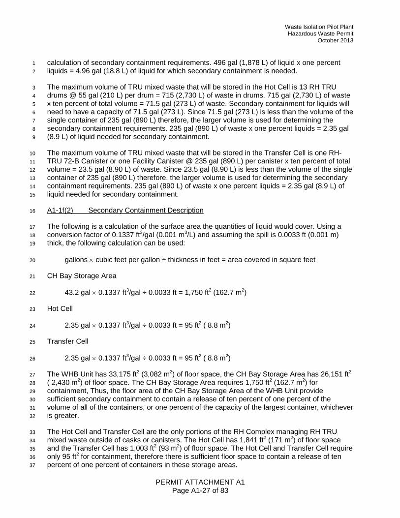
Waste Isolation Pilot Plant Hazardous Waste Permit
October 2013
PERMIT ATTACHMENT A1 Page A1-27 of 83
calculation of secondary containment requirements. 496 gal (1,878 L) of liquid x one percent 1 liquids = 4.96 gal (18.8 L) of liquid for which secondary containment is needed. 2
The maximum volume of TRU mixed waste that will be stored in the Hot Cell is 13 RH TRU 3 drums @ 55 gal (210 L) per drum = 715 (2,730 L) of waste in drums. 715 gal (2,730 L) of waste 4 x ten percent of total volume = 71.5 gal (273 L) of waste. Secondary containment for liquids will 5 need to have a capacity of 71.5 gal (273 L). Since 71.5 gal (273 L) is less than the volume of the 6 single container of 235 gal (890 L) therefore, the larger volume is used for determining the 7 secondary containment requirements. 235 gal (890 L) of waste x one percent liquids = 2.35 gal 8 (8.9 L) of liquid needed for secondary containment. 9
The maximum volume of TRU mixed waste that will be stored in the Transfer Cell is one RH-10 TRU 72-B Canister or one Facility Canister @ 235 gal (890 L) per canister x ten percent of total 11 volume = 23.5 gal (8.90 L) of waste. Since 23.5 gal (8.90 L) is less than the volume of the single 12 container of 235 gal (890 L) therefore, the larger volume is used for determining the secondary 13 containment requirements. 235 gal (890 L) of waste x one percent liquids = 2.35 gal (8.9 L) of 14 liquid needed for secondary containment. 15
A1-1f(2) Secondary Containment Description 16
The following is a calculation of the surface area the quantities of liquid would cover. Using a 17 conversion factor of 0.1337 ft3/gal (0.001 m3/L) and assuming the spill is 0.0033 ft (0.001 m) 18 thick, the following calculation can be used: 19
gallons × cubic feet per gallon ÷ thickness in feet = area covered in square feet 20
CH Bay Storage Area 21
43.2 gal × 0.1337 ft3/gal ÷ 0.0033 ft = 1,750 ft2 (162.7 m2) 22
Hot Cell 23
2.35 gal × 0.1337 ft3/gal ÷ 0.0033 ft = 95 ft2 ( 8.8 m2) 24
Transfer Cell 25
2.35 gal × 0.1337 ft3/gal ÷ 0.0033 ft = 95 ft2 ( 8.8 m2) 26
The WHB Unit has 33,175 ft2 (3,082 m2) of floor space, the CH Bay Storage Area has 26,151 ft2 27 ( 2,430 m2) of floor space. The CH Bay Storage Area requires 1,750 ft2 (162.7 m2) for 28 containment, Thus, the floor area of the CH Bay Storage Area of the WHB Unit provide 29 sufficient secondary containment to contain a release of ten percent of one percent of the 30 volume of all of the containers, or one percent of the capacity of the largest container, whichever 31 is greater. 32
The Hot Cell and Transfer Cell are the only portions of the RH Complex managing RH TRU 33 mixed waste outside of casks or canisters. The Hot Cell has 1,841 ft2 (171 m2) of floor space 34 and the Transfer Cell has 1,003 ft2 (93 m2) of floor space. The Hot Cell and Transfer Cell require 35 only 95 ft2 for containment, therefore there is sufficient floor space to contain a release of ten 36 percent of one percent of containers in these storage areas. 37
Waste Isolation Pilot Plant Hazardous Waste Permit October 2013
PERMIT ATTACHMENT A1 Page A1-28 of 83
In addition, both the Hot Cell and the Transfer Cell each contain a 220 gal (833 L) sump that will 1 collect any liquids that spill from containers. 2
Derived Waste Storage Area 3
The derived waste containers in the Derived Waste Storage Area will be stored on standard 4 drum pallets, which provides approximately 50 gal (190 L) of secondary containment capacity. 5 Thus the secondary containment capacity of the standard drum pallet is sufficient to contain a 6 release of ten percent of one percent of the largest container (4.96 gal or 18.8 L). 7
Parking Area Unit 8
Containers of TRU mixed waste to be stored in the Parking Area Unit will be in Contact-Handled 9 or Remote-Handled Packages. There will be no additional requirements for engineered 10 secondary containment systems. 11
A1-1g Special Requirements for Ignitable, Reactive, and Incompatible Waste 12
Special requirements for ignitable, reactive, and incompatible waste are addressed in 13 20.4.1.500 NMAC (incorporating 40 CFR §§264.176 and 264.177). Permit Part 2 precludes 14 ignitable, reactive, or incompatible waste at the WIPP. No additional measures are required. 15
A1-1h Closure 16
Clean closure is planned in accordance with 20.4.1.500 NMAC (incorporating 40 CFR 17 §264.178) for all permitted container storage areas. The applicable areas and the plans for 18 clean closure are detailed in Permit Attachment G. 19
A1-1i Control of Run On 20
The WHB Unit is located indoors which prevents run-on from a precipitation event. In addition, 21 the CH TRU containers are stored on facility pallets, containment pallets, or standard drum 22 pallets, which elevate the CH TRU mixed waste containers at least 6 in. (15 cm) off the floor, or 23 in Contact-Handled or Remote-Handled Packages, so that any firewater released in the building 24 will not pool around containers. Within the RH Bay, Cask Unloading Room, Transfer Cell, and 25 Facility Cask Loading Room, waste containers are stored in casks or Shielded Inserts and 26 protected from any potential run on. Any firewater released in the building will not pool around 27 the waste containers as they are stored in casks, or Shielded Inserts. Within the Hot Cell, there 28 is no source of water during operations. However, control of run-on is provided by the Lower Hot 29 Cell, which lies below a sloped floor surrounded by a grating and canister sleeves in the Hot 30 Cell above. 31
In the Parking Area Unit, the containers of TRU mixed waste are always in Contact-Handled or 32 Remote-Handled Packages which protect them from precipitation and run on. Therefore, the 33 WIPP container storage units will comply with the requirements of 20.4.1.500 NMAC 34 (incorporating 40 CFR §264.175(b)(4)). 35
36
Waste Isolation Pilot Plant Hazardous Waste Permit
October 2013
PERMIT ATTACHMENT A1 Page A1-29 of 83
References 1
DOE, 1997a. Resource Conservation and Recovery Act Part B Permit Application, Waste 2 Isolation Pilot Plant (WIPP), Carlsbad, New Mexico, Rev. 6.5, 1997. 3
DOE, 1997b. Waste Isolation Pilot Plant Safety Analysis Report (DOE/WIPP-95-2065, Rev. 1), 4 U.S. Department of Energy, Carlsbad Area Office, Carlsbad, NM, April 1997. 5
6

Waste Isolation Pilot Plant Hazardous Waste Permit October 2013
PERMIT ATTACHMENT A1 Page A1-30 of 83
(This page intentionally blank) 1
2

Waste Isolation Pilot Plant Hazardous Waste Permit
October 2013
PERMIT ATTACHMENT A1 Page A1-31 of 83
TABLES 1
2

Waste Isolation Pilot Plant Hazardous Waste Permit October 2013
PERMIT ATTACHMENT A1 Page A1-32 of 83
(This page intentionally blank) 1
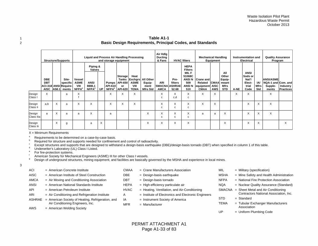
Waste Isolation Pilot Plant Hazardous Waste Permit
October 2013
PERMIT ATTACHMENT A1 Page A1-33 of 83
Table A1-1 1 Basic Design Requirements, Principal Codes, and Standards 2
Structure/Supports Liquid and Process Air Handling Processing
and storage equipment
Air Hdlg Ducting & Fans HVAC filters
Mechanical Handling Equipment
Instrumentation and Electrical
Quality Assurance Program
DBE DBT
ACI-318 AISC
ANSI A58.1
Site-specific Require-
ments
Vessel ASME
VIII NFPAe
Piping & Valves
Pumps API-610 NFPAe
Storage Tanks
API-650 or
API-620
Heat Exchgrs ASME
VIII TEMA
All Other Equip-ment
Mfrs Std
ARI SMACNA
AMCA
Pre- filters
ASHRAE 52.68
HEPA Filters MIL F
51068C ANSI N
509 ANSI N
510
Crane and Related
equipment CMAA
CMAA AISC AWS
All Other Equip-meant Mfrs STD A-NE
ANSI Sods or
Nat’l Elect-trial
Code
IA/ Mfrs Std
ANSI/ASME NQA-1 and
Supple- ments
Com. and Industry Practices
ANSI BBB,1 NFPAe UP
Design Class I
X a X f
X X X X c
X c,d
X c
X X X X X
Design Class Ii
a,b X a X X X X X X c
X c
X c
X X X X X
Design Class Iiia
a X a a X a X X c
X c
X c
a a X X X X
Design Class Iii
X g a X X X X X X X X X
X = Minimum Requirements a Requirements to be determined on a case-by-case basis. b Required for structure and supports needed for confinement and control of radioactivity. c Except structures and supports that are designed to withstand a design-basis earthquake (DBE)/design-basis tornado (DBT) when specified in column 1 of this table. d Underwriter’s Laboratory (UL) Class I Listed. e For fire-protection systems. f American Society for Mechanical Engineers (ASME) III for other Class I vessels. g Design of underground structures, mining equipment, and facilities are basically governed by the MSHA and experience in local mines. 3 ACI = American Concrete Institute AISC = American Institute of Steel Construction AMCA = Air Moving and Conditioning Association ANSI = American National Standards Institute API = American Petroleum Institute ARI = Air Conditioning and Refrigeration Institute ASHRAE = American Society of Heating, Refrigeration, and
Air Conditioning Engineers, Inc. AWS = American Welding Society
CMAA = Crane Manufacturers Association DBE = Design-basis earthquake DBT = Design-basis tornado HEPA = High-efficiency particulate air HVAC = Heating, Ventilation, and Air-Conditioning A = Institute of Electronics and Electronic Engineers IA = Instrument Society of America MFR = Manufacturer
MIL = Military (specification) MSHA = Mine Safety and Health Administration NFPA = National Fire Protection Association NQA = Nuclear Quality Assurance (Standard) SMACNA = Sheet Metal and Air Conditioning
Contractors National Association, Inc. STD = Standard TEMA = Tubular Exchanger Manufacturers
Association UP = Uniform Plumbing Code
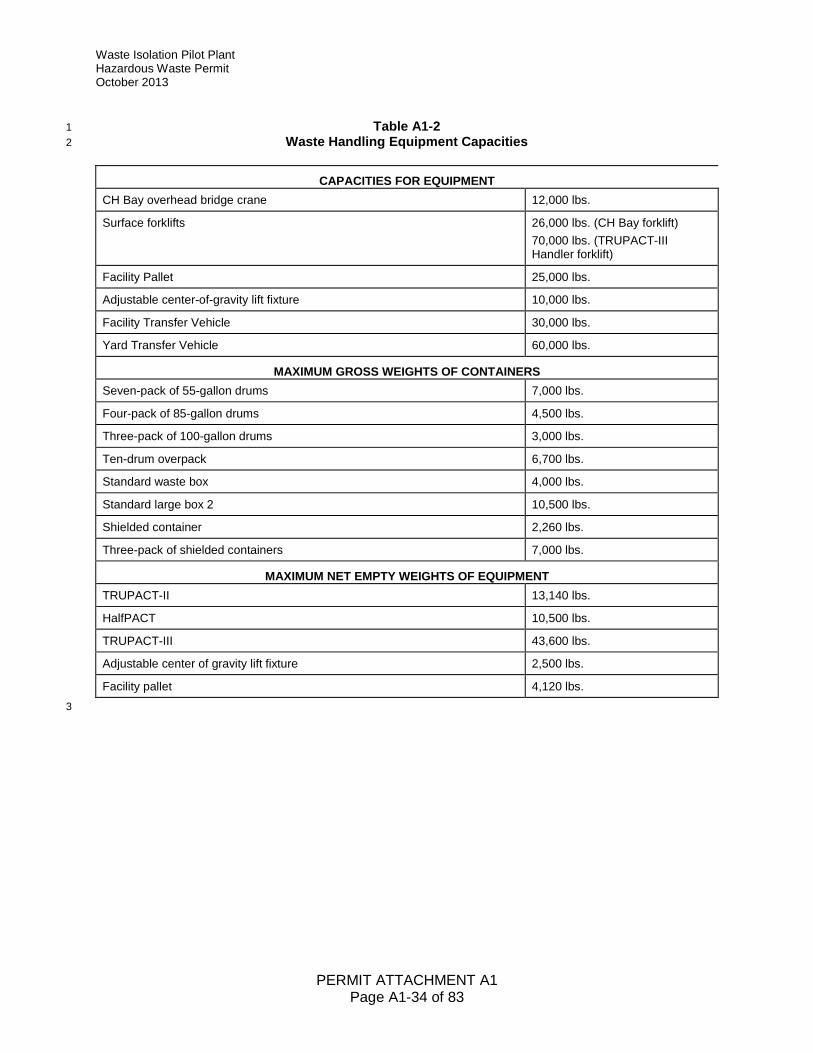
Waste Isolation Pilot Plant Hazardous Waste Permit October 2013
PERMIT ATTACHMENT A1 Page A1-34 of 83
Table A1-2 1 Waste Handling Equipment Capacities 2
CAPACITIES FOR EQUIPMENT CH Bay overhead bridge crane 12,000 lbs.
Surface forklifts 26,000 lbs. (CH Bay forklift) 70,000 lbs. (TRUPACT-III Handler forklift)
Facility Pallet 25,000 lbs.
Adjustable center-of-gravity lift fixture 10,000 lbs.
Facility Transfer Vehicle 30,000 lbs.
Yard Transfer Vehicle 60,000 lbs.
MAXIMUM GROSS WEIGHTS OF CONTAINERS Seven-pack of 55-gallon drums 7,000 lbs.
Four-pack of 85-gallon drums 4,500 lbs.
Three-pack of 100-gallon drums 3,000 lbs.
Ten-drum overpack 6,700 lbs.
Standard waste box 4,000 lbs.
Standard large box 2 10,500 lbs.
Shielded container 2,260 lbs.
Three-pack of shielded containers 7,000 lbs.
MAXIMUM NET EMPTY WEIGHTS OF EQUIPMENT TRUPACT-II 13,140 lbs.
HalfPACT 10,500 lbs.
TRUPACT-III 43,600 lbs.
Adjustable center of gravity lift fixture 2,500 lbs.
Facility pallet 4,120 lbs. 3
Waste Isolation Pilot Plant Hazardous Waste Permit
October 2013
PERMIT ATTACHMENT A1 Page A1-35 of 83
Table A1-3 1 RH TRU Mixed Waste Handling Equipment Capacities 2
CAPACITIES FOR EQUIPMENT RH Bay Overhead Bridge Crane 140 tons main hoist
25 tons auxiliary hoist
RH-TRU 72-B Cask Transfer Car 20 tons
CNS 10-160B Cask Transfer Car 35 tons
Transfer Cell Shuttle Car 29 tons
Hot Cell Bridge Crane 15 tons
Overhead Powered Manipulator 2.5 tons
Facility Cask Rotating Device No specific load rating
Cask Unloading Room Crane 25 tons
6.25 Ton Grapple Hoist 6.25 tons
Facility Cask Transfer Car 40 tons
MAXIMUM GROSS WEIGHTS OF RH TRU CONTAINERS RH TRU Canister 8,000 lbs
55-Gallon Drum 1,000 lbs
Facility Canister 10,000 lbs
MAXIMUM NET EMPTY WEIGHTS OF EQUIPMENT RH-TRU 72-B Cask 37,000 lbs
CNS 10-160B Cask 57,500 lbs
Facility Cask 67,700 lbs
Shielded Insert 26,300 lbs
3
Waste Isolation Pilot Plant Hazardous Waste Permit October 2013
PERMIT ATTACHMENT A1 Page A1-36 of 83
(This page intentionally blank) 1
2
Waste Isolation Pilot Plant Hazardous Waste Permit
October 2013
PERMIT ATTACHMENT A1 Page A1-37 of 83
FIGURES 1
2
Waste Isolation Pilot Plant Hazardous Waste Permit October 2013
PERMIT ATTACHMENT A1 Page A1-38 of 83
(This page intentionally blank) 1

Waste Isolation Pilot Plant Hazardous Waste Permit
October 2013
PERMIT ATTACHMENT A1 Page A1-39 of 83
Figure A1-1 Waste Handling Building - CH TRU Mixed Waste Container Storage and Surge Areas
Waste Isolation Pilot Plant Hazardous Waste Permit October 2013
PERMIT ATTACHMENT A1 Page A1-40 of 83
Figure A1-1a Waste Handling Building Plan (Ground Floor)
Waste Isolation Pilot Plant Hazardous Waste Permit
October 2013
PERMIT ATTACHMENT A1 Page A1-41 of 83
Figure A1-1b Waste Handling Building Plan (Room 108 Detail)
Waste Isolation Pilot Plant Hazardous Waste Permit October 2013
PERMIT ATTACHMENT A1 Page A1-42 of 83
Figure A1-2 Parking Area - Container Storage and Surge Areas
Waste Isolation Pilot Plant Hazardous Waste Permit
October 2013
PERMIT ATTACHMENT A1 Page A1-43 of 83
Figure A1-3 Standard 55-Gallon Drum (Typical)
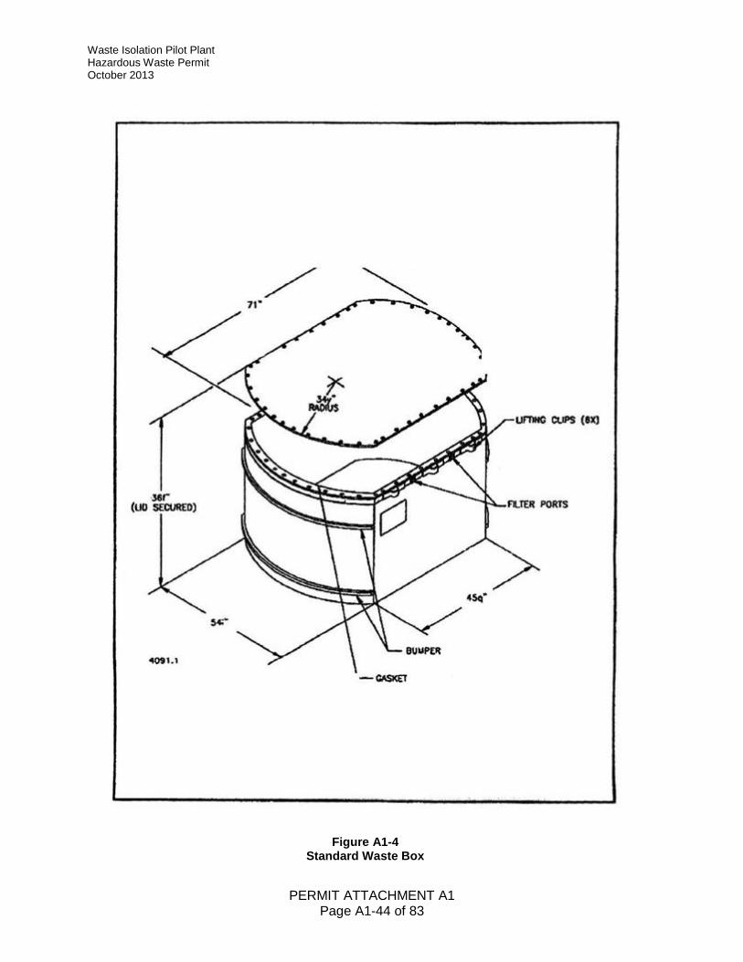
Waste Isolation Pilot Plant Hazardous Waste Permit October 2013
PERMIT ATTACHMENT A1 Page A1-44 of 83
Figure A1-4 Standard Waste Box
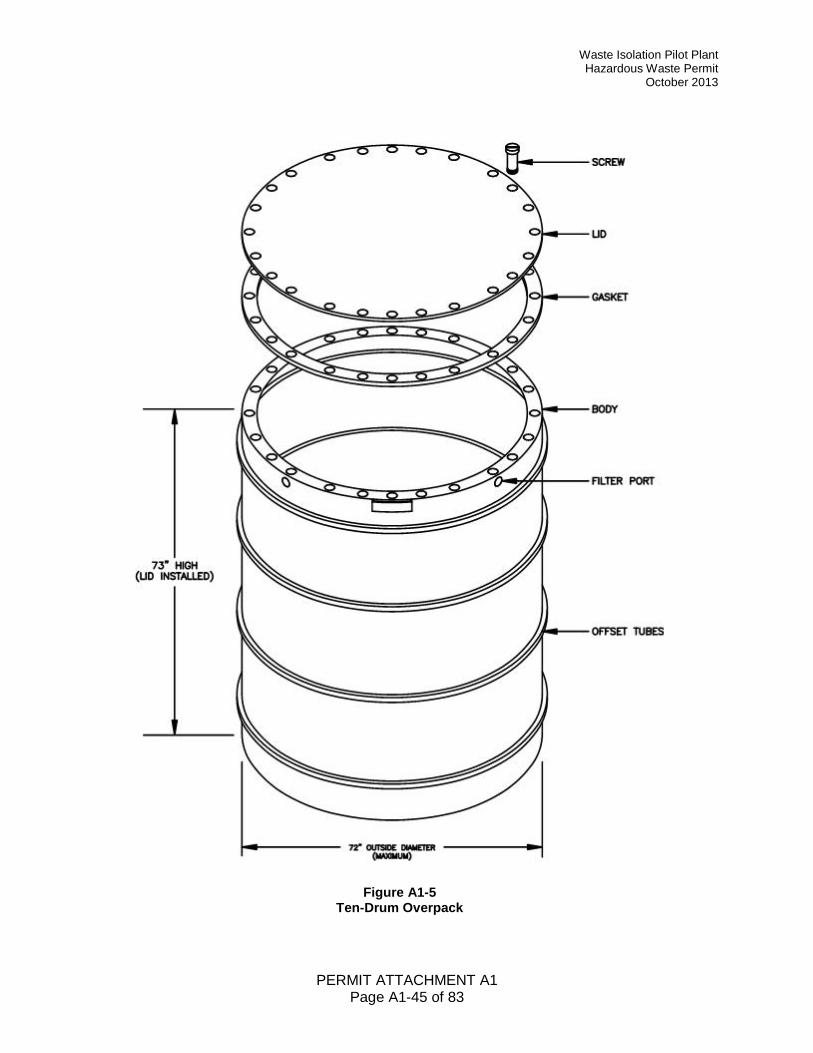
Waste Isolation Pilot Plant Hazardous Waste Permit
October 2013
PERMIT ATTACHMENT A1 Page A1-45 of 83
Figure A1-5 Ten-Drum Overpack
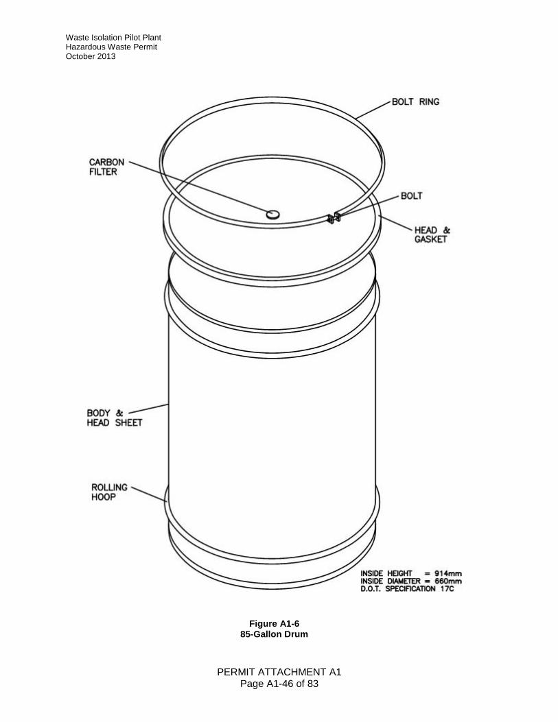
Waste Isolation Pilot Plant Hazardous Waste Permit October 2013
PERMIT ATTACHMENT A1 Page A1-46 of 83
Figure A1-6 85-Gallon Drum
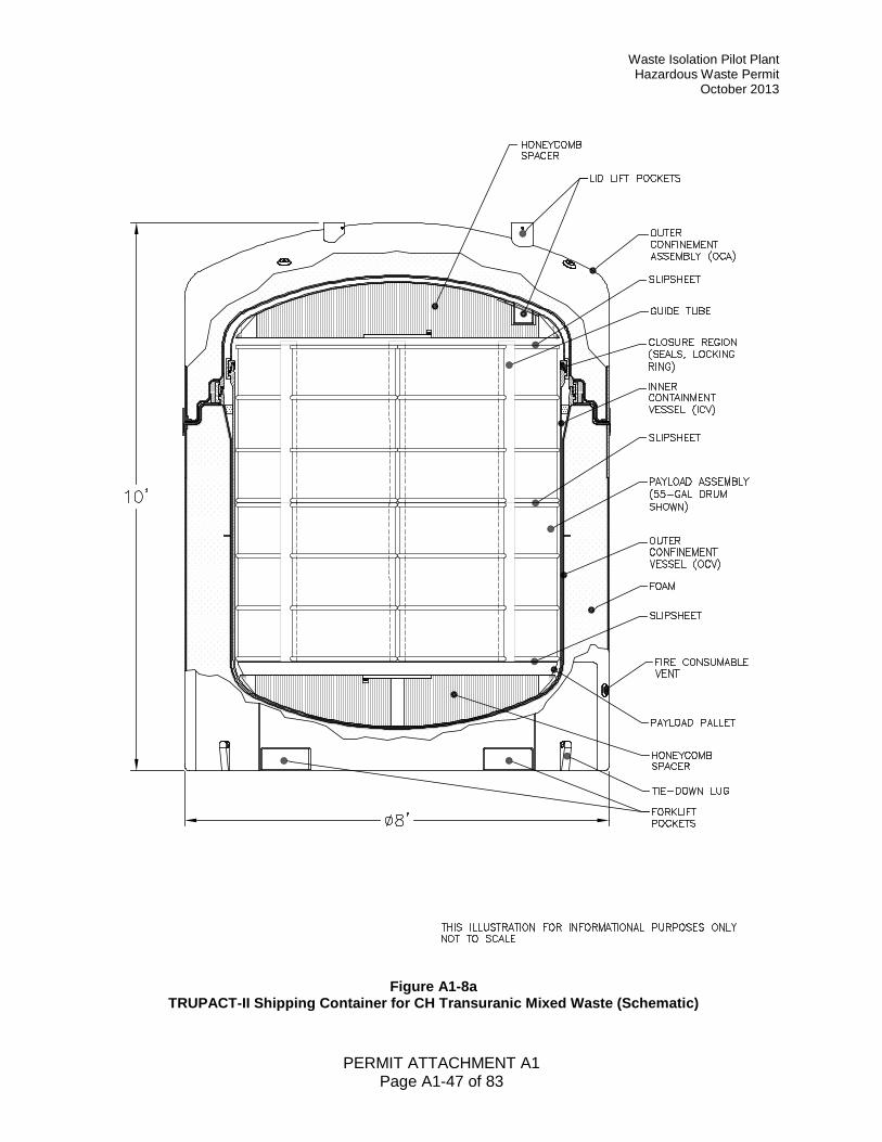
Waste Isolation Pilot Plant Hazardous Waste Permit
October 2013
PERMIT ATTACHMENT A1 Page A1-47 of 83
Figure A1-8a TRUPACT-II Shipping Container for CH Transuranic Mixed Waste (Schematic)
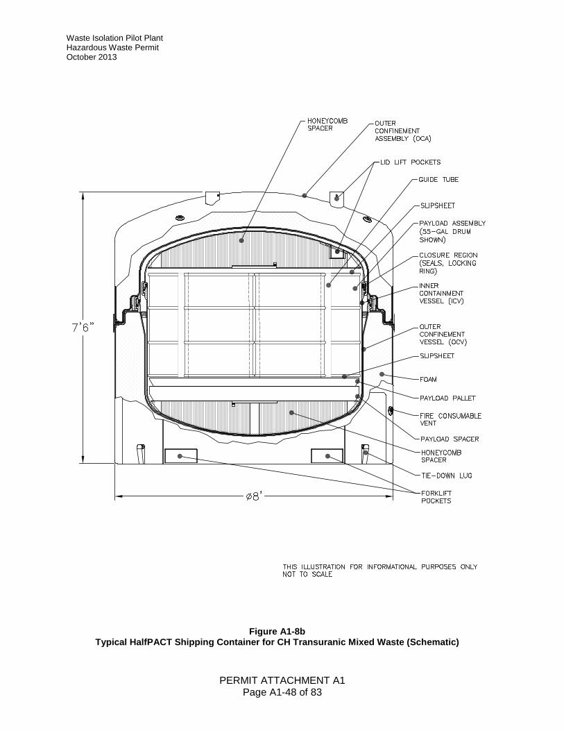
Waste Isolation Pilot Plant Hazardous Waste Permit October 2013
PERMIT ATTACHMENT A1 Page A1-48 of 83
Figure A1-8b Typical HalfPACT Shipping Container for CH Transuranic Mixed Waste (Schematic)
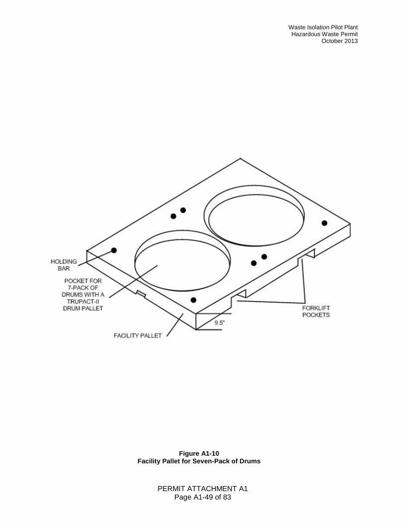
Waste Isolation Pilot Plant Hazardous Waste Permit
October 2013
PERMIT ATTACHMENT A1 Page A1-49 of 83
Figure A1-10 Facility Pallet for Seven-Pack of Drums
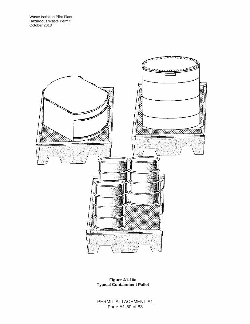
Waste Isolation Pilot Plant Hazardous Waste Permit October 2013
PERMIT ATTACHMENT A1 Page A1-50 of 83
Figure A1-10a Typical Containment Pallet
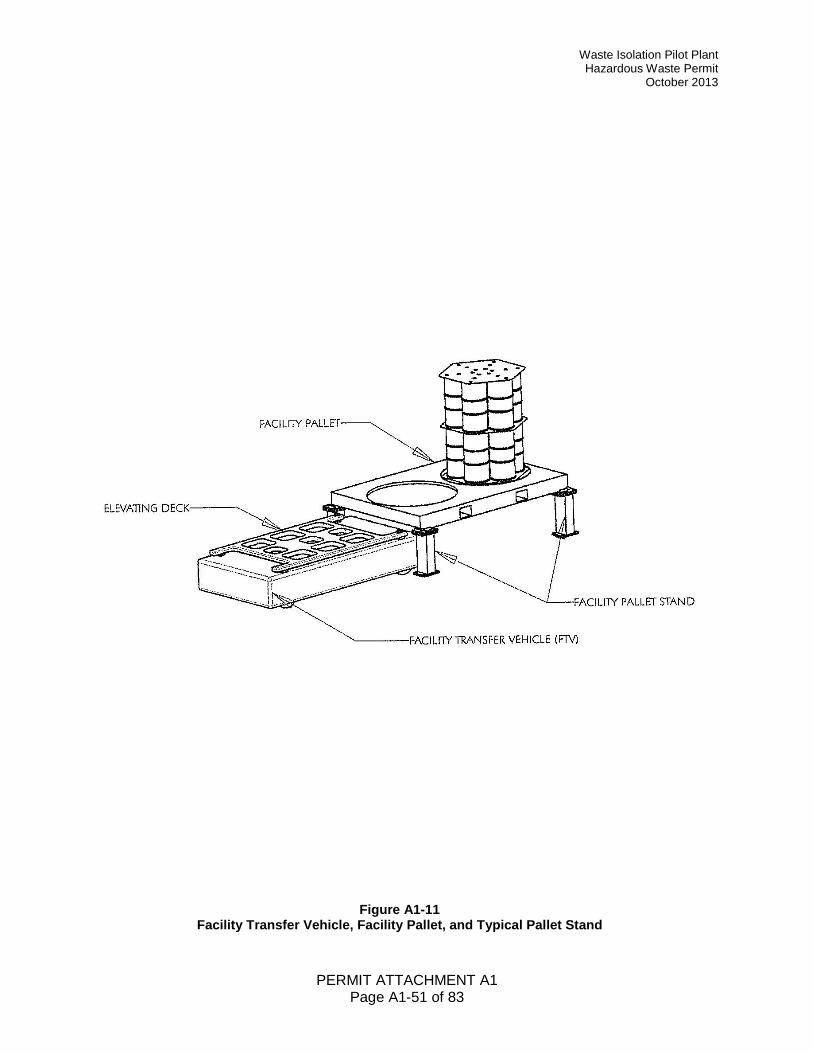
Waste Isolation Pilot Plant Hazardous Waste Permit
October 2013
PERMIT ATTACHMENT A1 Page A1-51 of 83
Figure A1-11 Facility Transfer Vehicle, Facility Pallet, and Typical Pallet Stand
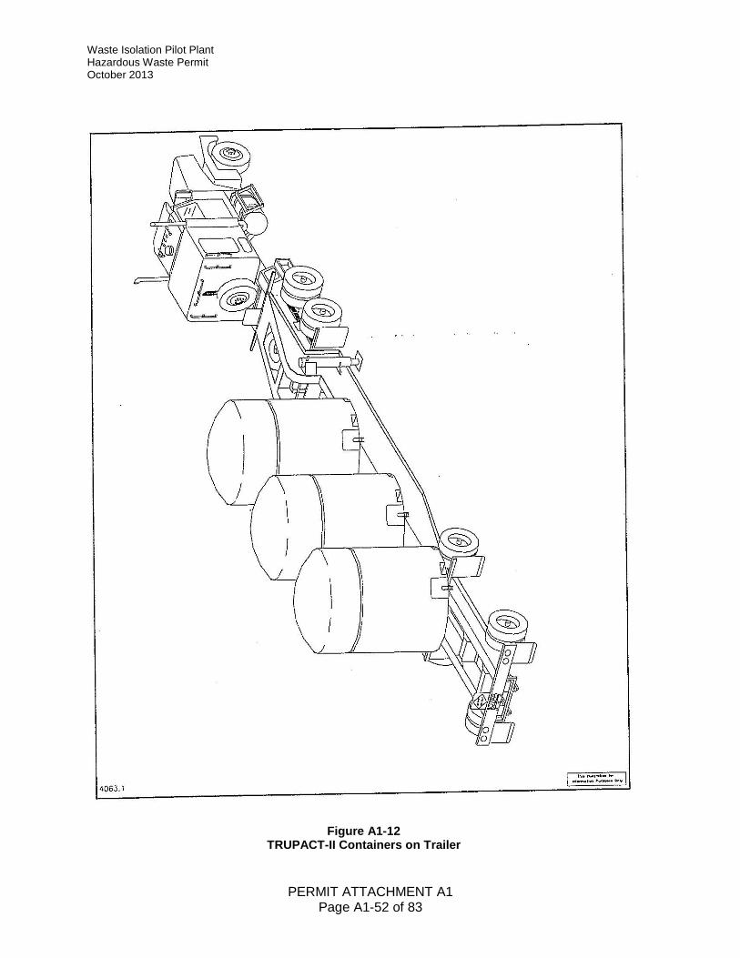
Waste Isolation Pilot Plant Hazardous Waste Permit October 2013
PERMIT ATTACHMENT A1 Page A1-52 of 83
Figure A1-12 TRUPACT-II Containers on Trailer
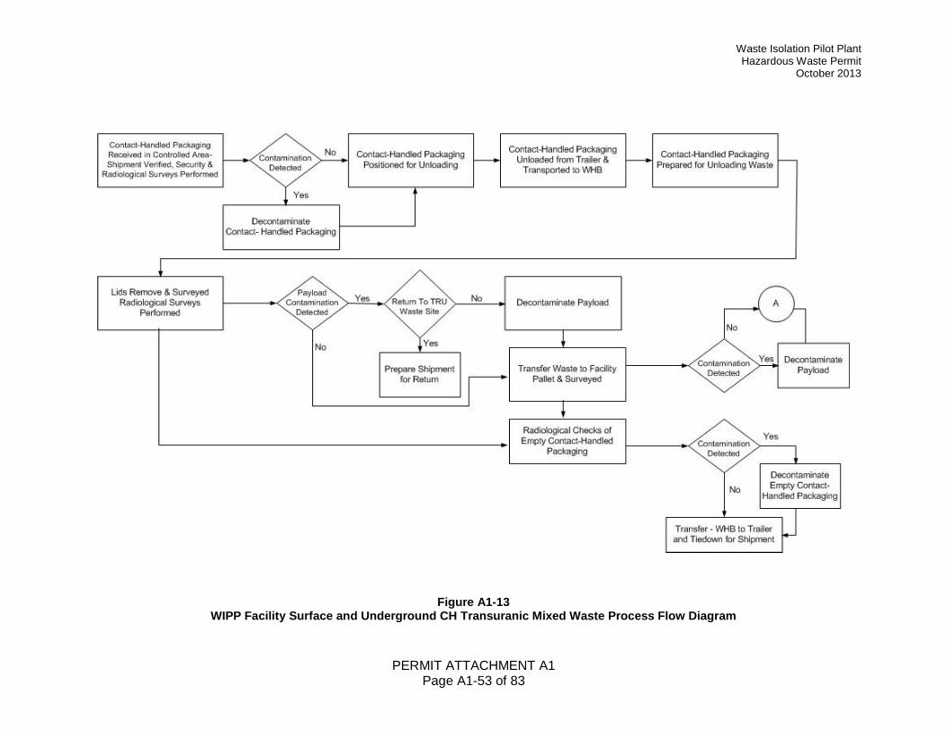
Waste Isolation Pilot Plant Hazardous Waste Permit
October 2013
PERMIT ATTACHMENT A1 Page A1-53 of 83
Figure A1-13 WIPP Facility Surface and Underground CH Transuranic Mixed Waste Process Flow Diagram
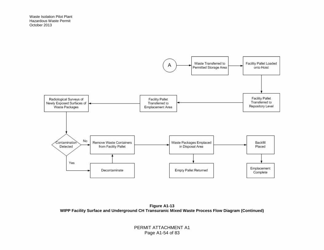
Waste Isolation Pilot Plant Hazardous Waste Permit October 2013
PERMIT ATTACHMENT A1 Page A1-54 of 83
Figure A1-13 WIPP Facility Surface and Underground CH Transuranic Mixed Waste Process Flow Diagram (Continued)
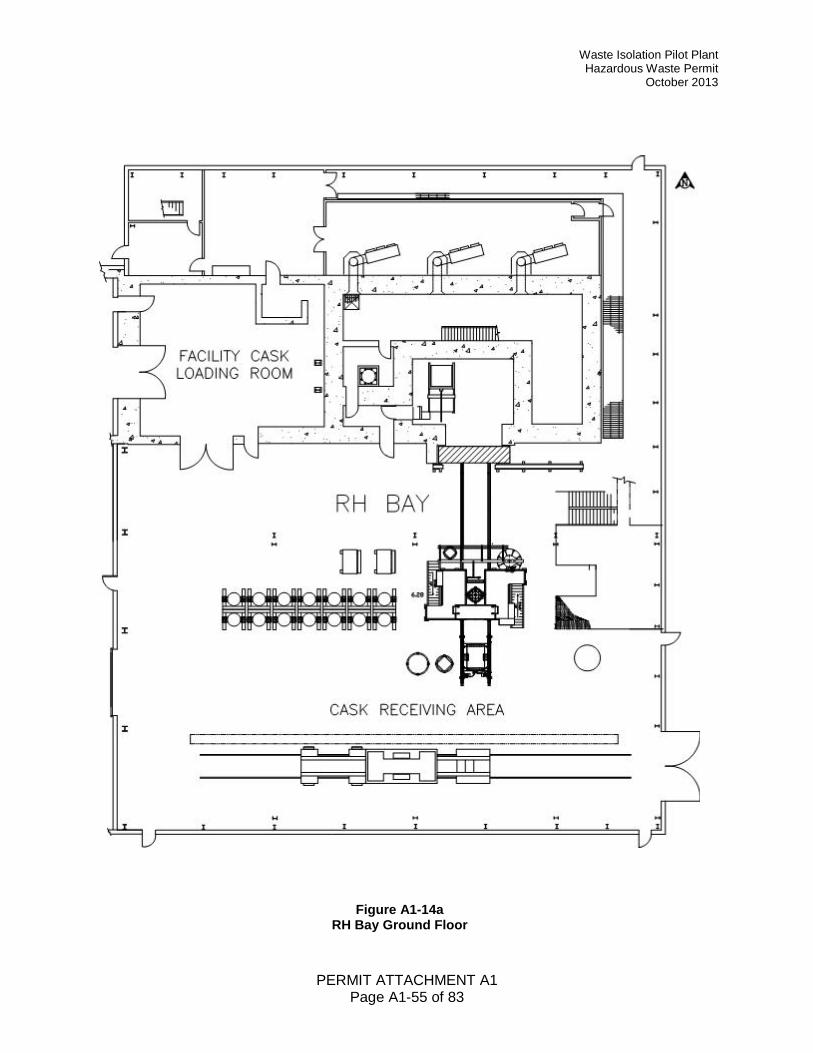
Waste Isolation Pilot Plant Hazardous Waste Permit
October 2013
PERMIT ATTACHMENT A1 Page A1-55 of 83
Figure A1-14a RH Bay Ground Floor
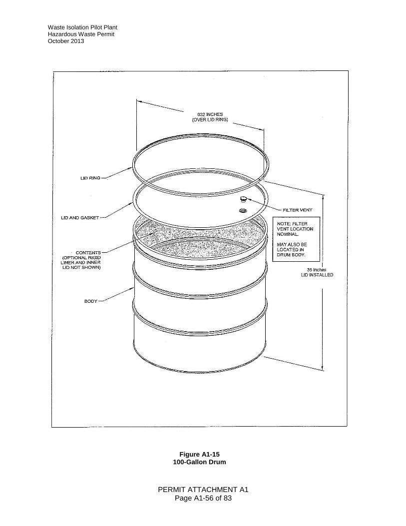
Waste Isolation Pilot Plant Hazardous Waste Permit October 2013
PERMIT ATTACHMENT A1 Page A1-56 of 83
Figure A1-15 100-Gallon Drum
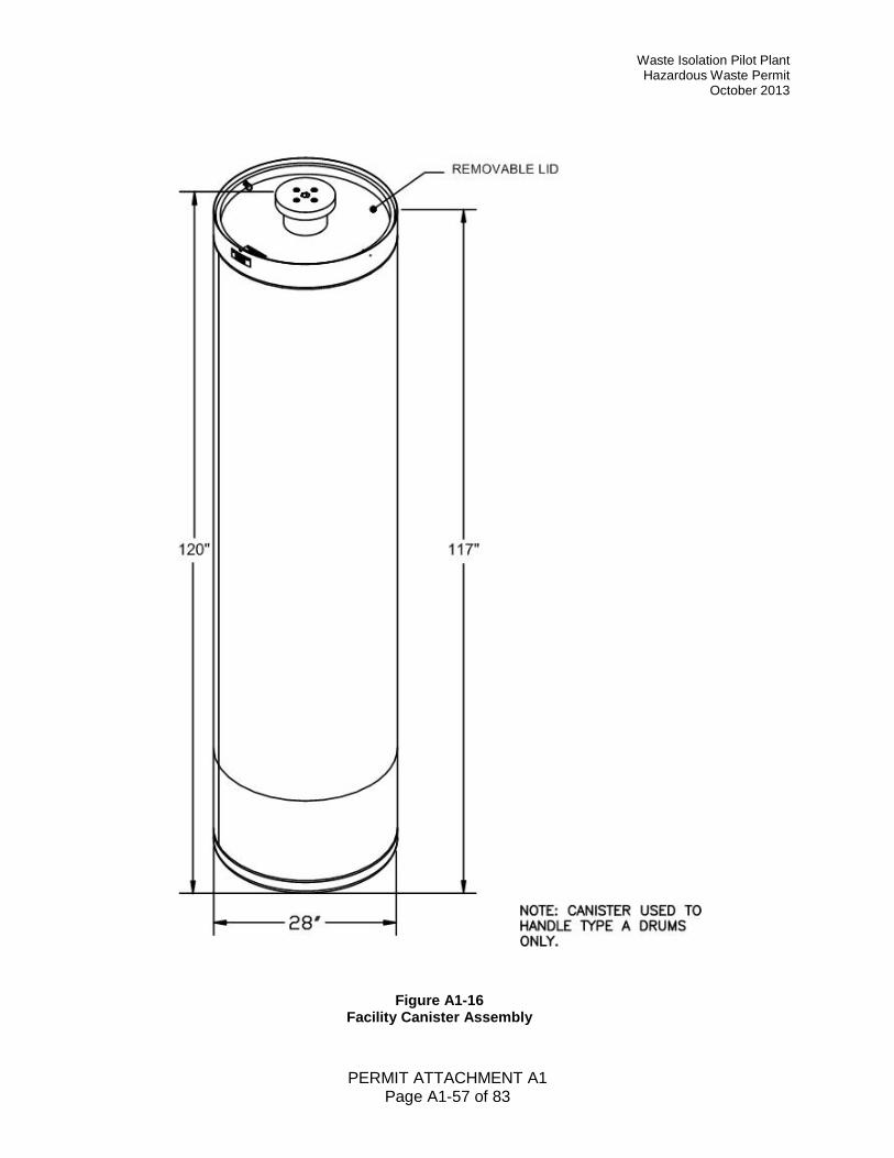
Waste Isolation Pilot Plant Hazardous Waste Permit
October 2013
PERMIT ATTACHMENT A1 Page A1-57 of 83
Figure A1-16 Facility Canister Assembly
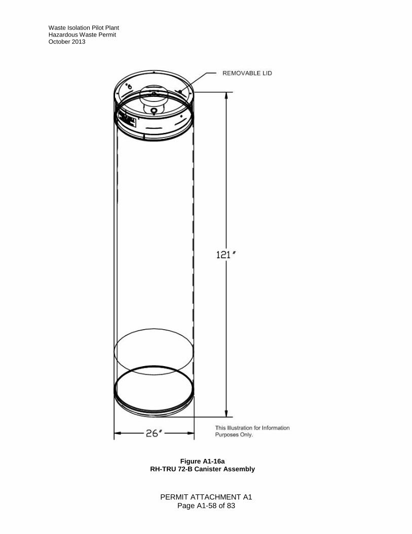
Waste Isolation Pilot Plant Hazardous Waste Permit October 2013
PERMIT ATTACHMENT A1 Page A1-58 of 83
Figure A1-16a RH-TRU 72-B Canister Assembly
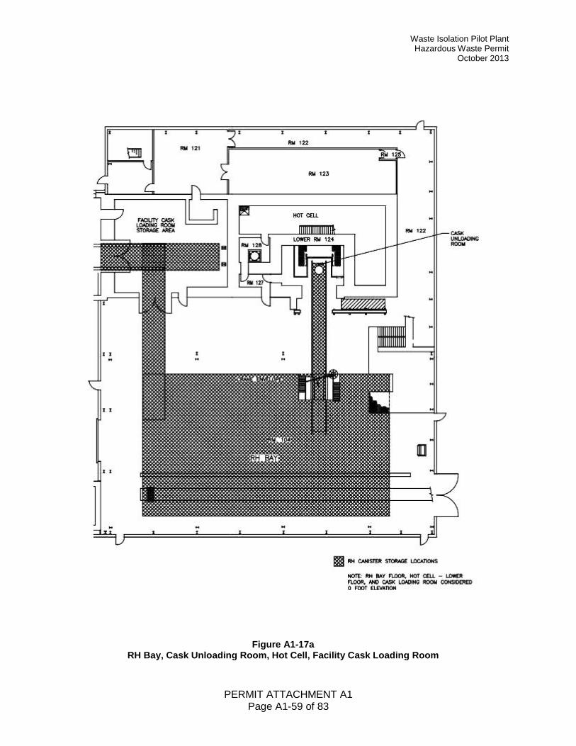
Waste Isolation Pilot Plant Hazardous Waste Permit
October 2013
PERMIT ATTACHMENT A1 Page A1-59 of 83
Figure A1-17a RH Bay, Cask Unloading Room, Hot Cell, Facility Cask Loading Room
Waste Isolation Pilot Plant Hazardous Waste Permit October 2013
PERMIT ATTACHMENT A1 Page A1-60 of 83
Figure A1-17b RH Hot Cell Storage Area
Waste Isolation Pilot Plant Hazardous Waste Permit
October 2013
PERMIT ATTACHMENT A1 Page A1-61 of 83
Figure A1-17c RH Canister Transfer Cell Storage Area
Waste Isolation Pilot Plant Hazardous Waste Permit October 2013
PERMIT ATTACHMENT A1 Page A1-62 of 83
Figure A1-17d RH Facility Cask Loading Room Storage Area
Waste Isolation Pilot Plant Hazardous Waste Permit
October 2013
PERMIT ATTACHMENT A1 Page A1-63 of 83
Figure A1-18 RH-TRU 72-B Shipping Cask on Trailer
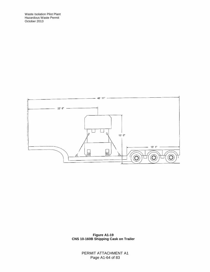
Waste Isolation Pilot Plant Hazardous Waste Permit October 2013
PERMIT ATTACHMENT A1 Page A1-64 of 83
Figure A1-19 CNS 10-160B Shipping Cask on Trailer
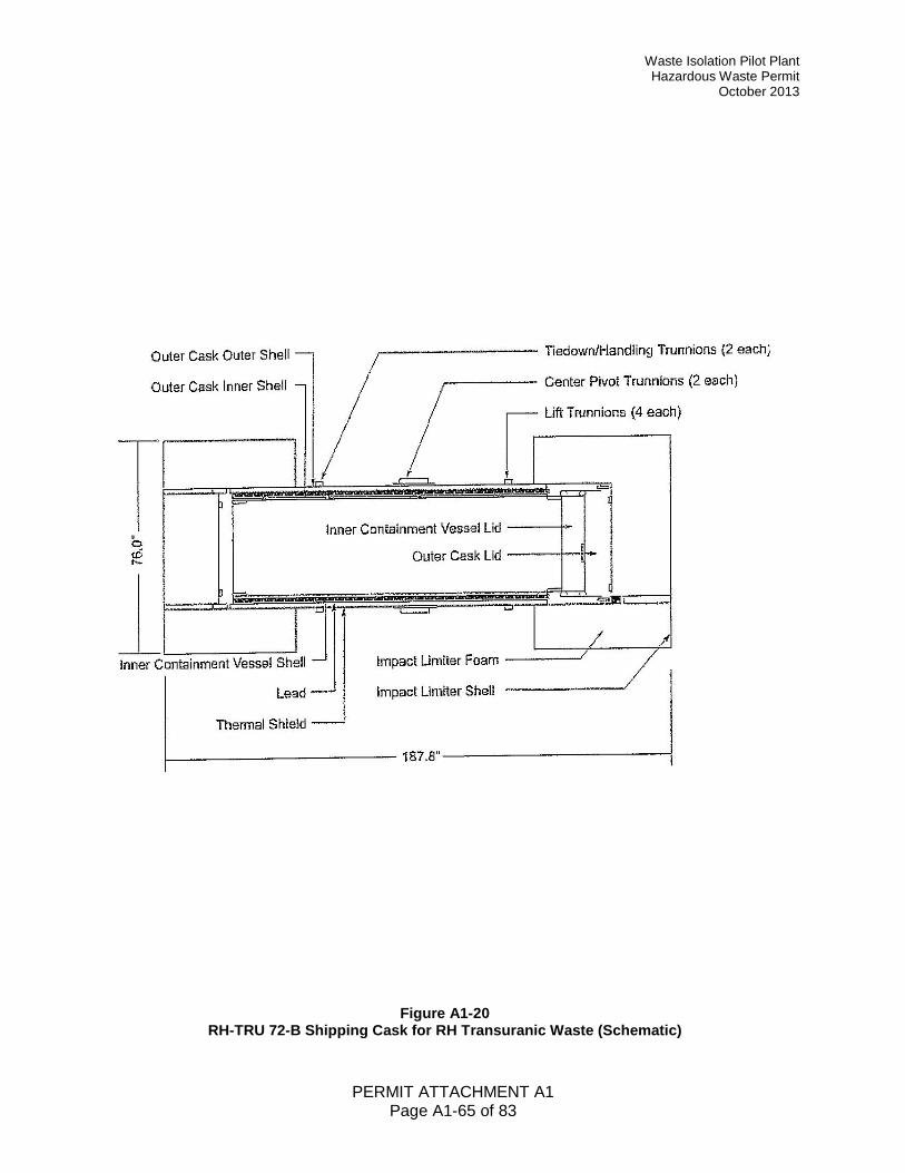
Waste Isolation Pilot Plant Hazardous Waste Permit
October 2013
PERMIT ATTACHMENT A1 Page A1-65 of 83
Figure A1-20 RH-TRU 72-B Shipping Cask for RH Transuranic Waste (Schematic)
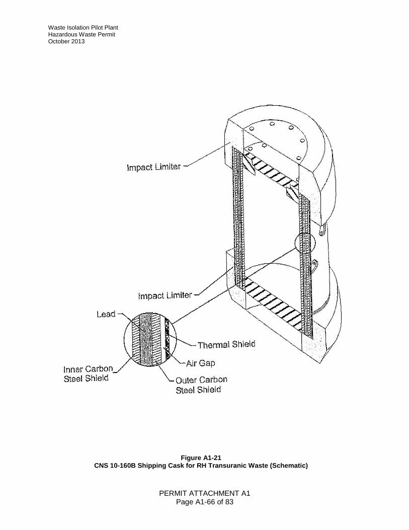
Waste Isolation Pilot Plant Hazardous Waste Permit October 2013
PERMIT ATTACHMENT A1 Page A1-66 of 83
Figure A1-21 CNS 10-160B Shipping Cask for RH Transuranic Waste (Schematic)
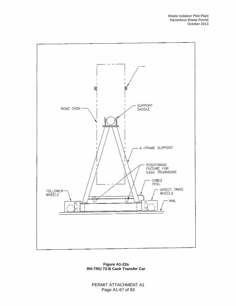
Waste Isolation Pilot Plant Hazardous Waste Permit
October 2013
PERMIT ATTACHMENT A1 Page A1-67 of 83
Figure A1-22a RH-TRU 72-B Cask Transfer Car
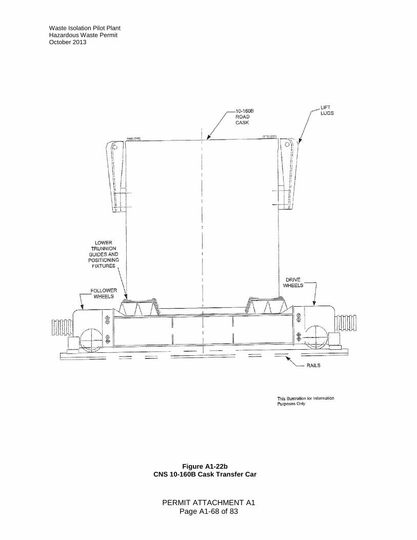
Waste Isolation Pilot Plant Hazardous Waste Permit October 2013
PERMIT ATTACHMENT A1 Page A1-68 of 83
Figure A1-22b CNS 10-160B Cask Transfer Car
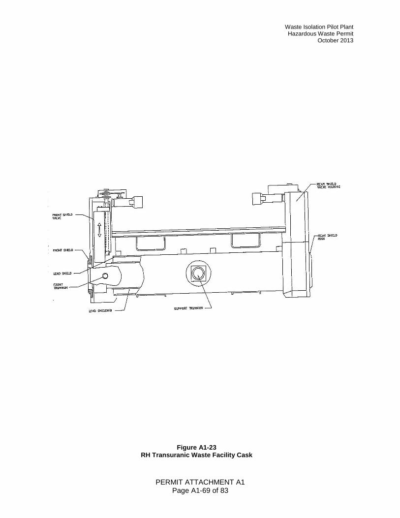
Waste Isolation Pilot Plant Hazardous Waste Permit
October 2013
PERMIT ATTACHMENT A1 Page A1-69 of 83
Figure A1-23 RH Transuranic Waste Facility Cask
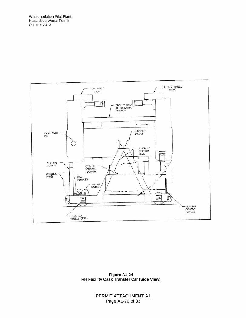
Waste Isolation Pilot Plant Hazardous Waste Permit October 2013
PERMIT ATTACHMENT A1 Page A1-70 of 83
Figure A1-24 RH Facility Cask Transfer Car (Side View)
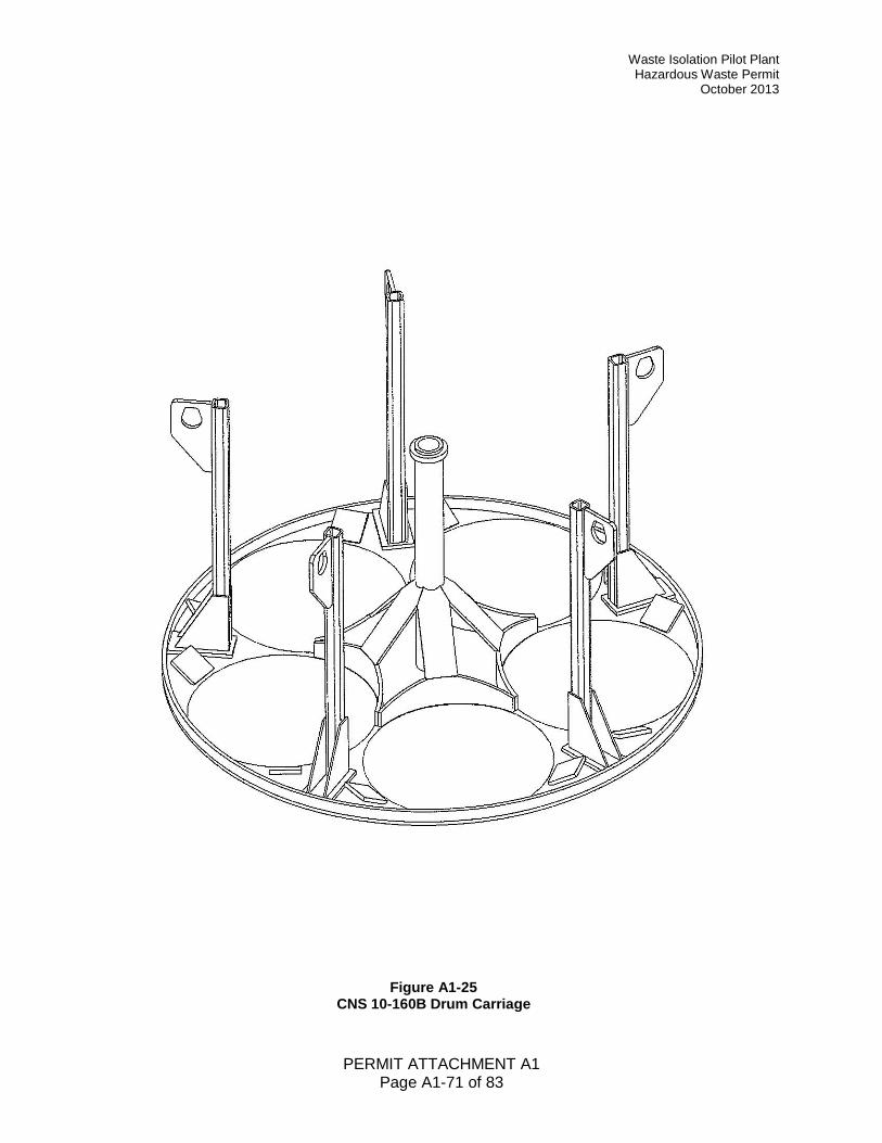
Waste Isolation Pilot Plant Hazardous Waste Permit
October 2013
PERMIT ATTACHMENT A1 Page A1-71 of 83
Figure A1-25 CNS 10-160B Drum Carriage
Waste Isolation Pilot Plant Hazardous Waste Permit October 2013
PERMIT ATTACHMENT A1 Page A1-72 of 83
Figure A1-26
Surface and Underground RH Transuranic Mixed Waste Process Flow Diagram for RH-TRU 72-B Shipping Cask
Waste Isolation Pilot Plant Hazardous Waste Permit
October 2013
PERMIT ATTACHMENT A1 Page A1-73 of 83
Figure A1-27
Surface and Underground RH Transuranic Mixed Waste Process Flow Diagram for CNS 10-160B Shipping Cask

Waste Isolation Pilot Plant Hazardous Waste Permit October 2013
PERMIT ATTACHMENT A1 Page A1-74 of 83
Figure A1-28 Schematic of the RH Transuranic Mixed Waste Process for RH-TRU 72-B Shipping Cask
Waste Isolation Pilot Plant Hazardous Waste Permit
October 2013
PERMIT ATTACHMENT A1 Page A1-75 of 83
Figure A1-29 Schematic of the RH Transuranic Mixed Waste Process for CNS 10-160B Shipping Cask
Waste Isolation Pilot Plant Hazardous Waste Permit October 2013
PERMIT ATTACHMENT A1 Page A1-76 of 83
Figure A1-30 RH Shielded Insert Assembly
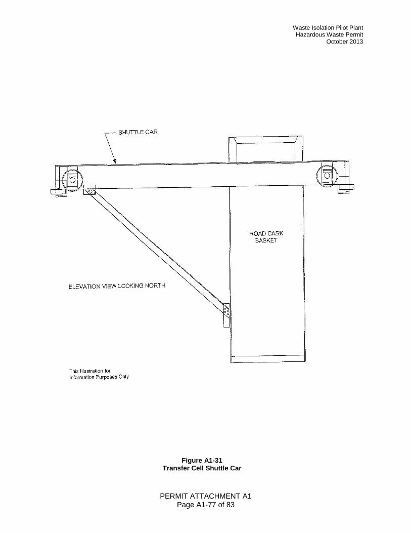
Waste Isolation Pilot Plant Hazardous Waste Permit
October 2013
PERMIT ATTACHMENT A1 Page A1-77 of 83
Figure A1-31 Transfer Cell Shuttle Car
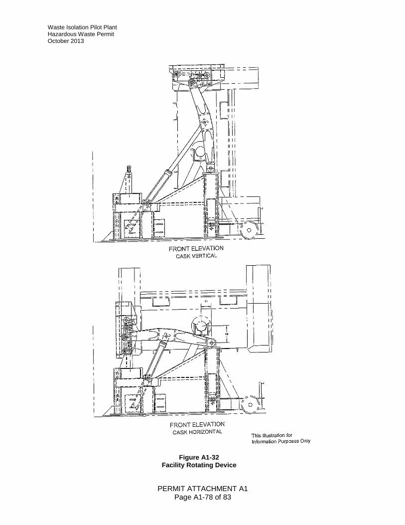
Waste Isolation Pilot Plant Hazardous Waste Permit October 2013
PERMIT ATTACHMENT A1 Page A1-78 of 83
Figure A1-32 Facility Rotating Device
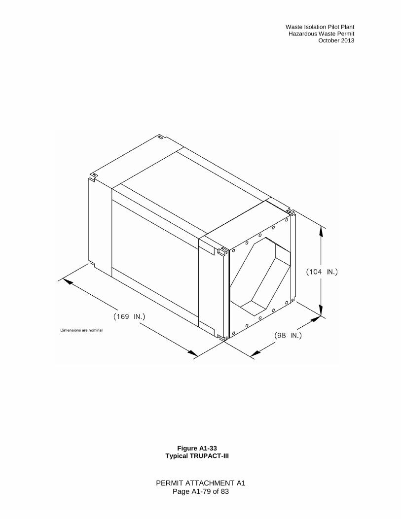
Waste Isolation Pilot Plant Hazardous Waste Permit
October 2013
PERMIT ATTACHMENT A1 Page A1-79 of 83
Figure A1-33 Typical TRUPACT-III
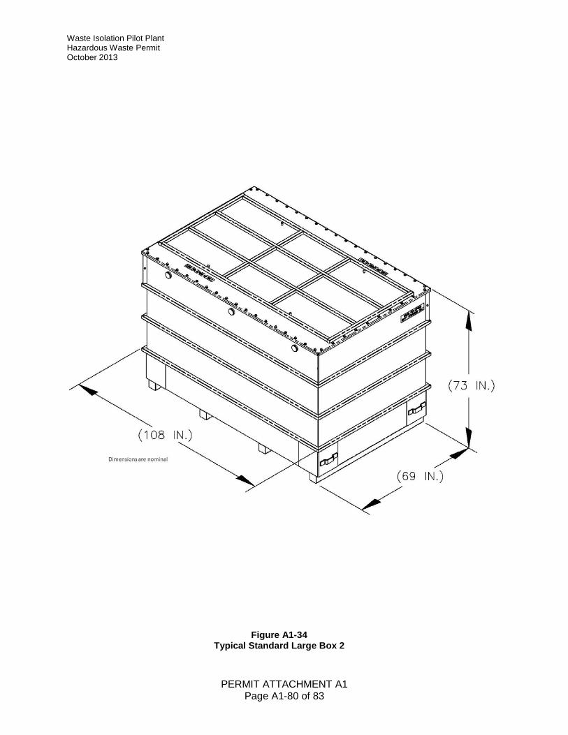
Waste Isolation Pilot Plant Hazardous Waste Permit October 2013
PERMIT ATTACHMENT A1 Page A1-80 of 83
Figure A1-34 Typical Standard Large Box 2
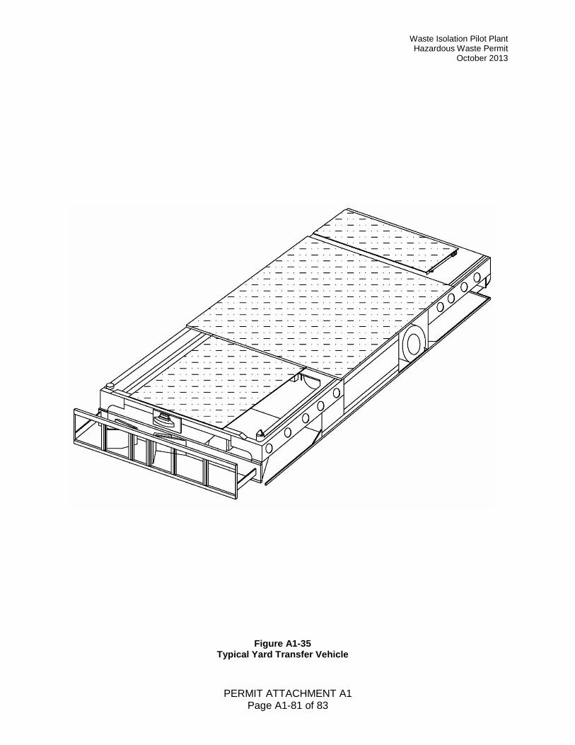
Waste Isolation Pilot Plant Hazardous Waste Permit
October 2013
PERMIT ATTACHMENT A1 Page A1-81 of 83
Figure A1-35 Typical Yard Transfer Vehicle
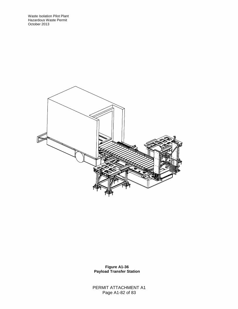
Waste Isolation Pilot Plant Hazardous Waste Permit October 2013
PERMIT ATTACHMENT A1 Page A1-82 of 83
Figure A1-36 Payload Transfer Station
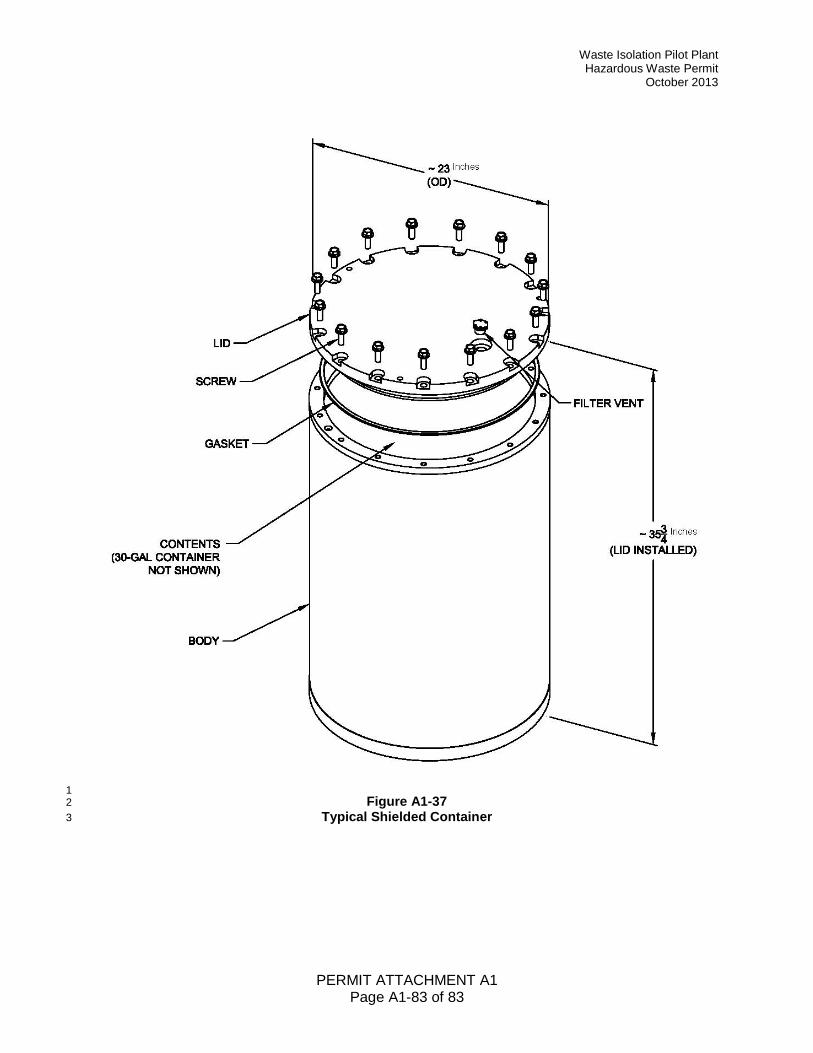
Waste Isolation Pilot Plant Hazardous Waste Permit
October 2013
PERMIT ATTACHMENT A1 Page A1-83 of 83
1 Figure A1-37 2
Typical Shielded Container 3