Embed Size (px)
Citation preview

Attachment A
New Specifications Section 15
Sound Barriers

SECTION 15: DESIGN OF SOUND BARRIERS
TABLE OF CONTENTS
i
15.1—SCOPE........................................................................................................................................................... 115.2—DEFINITIONS .............................................................................................................................................. 115.3—NOTATION................................................................................................................................................... 115.4—GENERAL FEATURES................................................................................................................................ 2
15.4.1—Functional Requirements ..................................................................................................................... 215.4.1.1 General ......................................................................................................................................... 215.4.1.2 —Lateral Clearance...................................................................................................................... 2
15.4.2—Drainage............................................................................................................................................... 215.4.3—Emergency Responders and Maintenance Access ............................................................................... 215.4.4—Differential Settlement of Foundations ................................................................................................ 3
15.5—LIMIT STATES AND RESISTANCE FACTORS ....................................................................................... 315.5.1—General ................................................................................................................................................ 315.5.2—Service Limit State............................................................................................................................... 315.5.3—Strength Limit State ............................................................................................................................. 415.5.4—Extreme Event Limit State ................................................................................................................... 4
15.6—EXPANSION DEVICES ............................................................................................................................... 415.6.1—General ................................................................................................................................................ 415.6.2—Structure-Mounted Sound Barriers ...................................................................................................... 415.6.3—Ground-Mounted Sound Barriers ........................................................................................................ 5
15.7—SOUND BARRIERS INSTALLED ON EXISTING BRIDGES................................................................... 515.8—LOADS.......................................................................................................................................................... 5
15.8.1—General ................................................................................................................................................ 515.8.2—Wind Load ........................................................................................................................................... 515.8.3—Seismic Load ....................................................................................................................................... 915.8.4—Earth Load ........................................................................................................................................... 915.8.5—Vehicular Collision Forces .................................................................................................................. 9
15.9—FOUNDATION DESIGN............................................................................................................................ 1215.9.1—General .............................................................................................................................................. 1215.9.2—Determination of Soil and Rock Properties ....................................................................................... 1215.9.3—Limit States........................................................................................................................................ 1215.9.4—Resistance Requirements ................................................................................................................... 1215.9.5—Resistance Factors ............................................................................................................................. 1315.9.6—Loading.............................................................................................................................................. 1315.9.7—Movement and Stability at the Service Limit State............................................................................ 13
15.9.7.1—Movement................................................................................................................................ 1315.9.7.2—Overall Stability....................................................................................................................... 13
15.9.8—Safety Against Geotechnical Failure at the Strength Limit State ....................................................... 1315.9.9—Seismic Design .................................................................................................................................. 1315.9.10—Corrosion Protection........................................................................................................................ 1315.9.11—Drainage........................................................................................................................................... 13


1
SECTION 15
DESIGN OF SOUND BARRIERS
15.1—SCOPE
This Section applies to the structural design of soundbarriers which are either ground-mounted or structure-mounted and the design of the foundations of ground-mounted sound barriers.
C15.1
This Section specifies the design forces, and the designrequirements unique to sound barriers constructed alonghighways. This Section does not cover sound barriersconstructed adjacent to railroad tracks or the acousticalrequirements for sound barriers.
These provisions are largely based on the requirementsof the Guide Specifications for Structural Design of SoundBarriers (1989).
15.2—DEFINITIONS
Clear Zone—The total roadside border area, starting at the edge of the traveled way, available for safe use by errantvehicles.
Crashworthy—A traffic railing system that has been successfully crash-tested to a currently acceptable crash test matrixand test level or one that can be geometrically and structurally evaluated as equal to a crash-tested system.
Ground-Mounted Sound Barriers—Sound barriers supported on shallow or deep foundations.
Post-and-Panel Construction—Type of sound barriers construction consisting of vertical posts supported on a structure oron the foundations and panels spanning horizontally between adjacent posts.
Right-of-Way—The land on which a roadway and its associated facilities and appurtenances are located. The highwayright-of-way is owned and maintained by the agency having jurisdiction over that specific roadway.
Right-of-Way Line—The boundary of the right-of-way
Sound Barrier—A wall constructed along a highway to lower the highway noise level in the area behind the wall.
Sound Barrier Setback—The distance between the point on the traffic face of the sound barrier wall that is closest to trafficand the closest point on the traffic face of the traffic railing the sound barrier is mounted on or located behind as defined inArticle 15.8.5.
Structure-Mounted Sound Barriers—Sound barrier supported on bridges, crashworthy traffic railings or retaining walls.
Traffic Railing—Synonymous with vehicular railing; used as a bridge or structure-mounted railing, rather than a guardrailor median barrier as in other publications.
15.3—NOTATION
S = setback distance of sound barrier (15.8.5)V0 = friction velocity, a meteorological wind characteristic for various upwind surface characteristics (mph)
(15.8.2)V30 = wind speed at 30.0 ft above low ground or water level (mph) (15.8.2)Z0 = friction length of upstream fetch, a meteorological wind characteristic (ft.) (15.8.2)φ = soil angle of internal friction (°) (C15.4.2) p = load factor for permanent loads (15.9.9)

2
15.4—GENERAL FEATURES
15.4.1—Functional Requirements
15.4.1.1 General
Consult a roadway professional for requirements forsight-distance and sound barrier height and lengthrequirements.
15.4.1.2 —Lateral Clearance
Unless dictated by site conditions and approved by theOwner, sound barriers shall be located outside the clearzone or, when the clear zone is wider than the distancebetween the edge of the traffic lanes and the edge of theavailable right-of-way, just inside the right-of-way.
C15.4.1.2
Locating the sound barrier farther from the edge of thetraffic lanes reduces the possibility of vehicular collisionwith the barrier. The most desirable location for a soundbarrier is outside the clear zone which minimizes thepossibility of vehicular collision. In many cases, becausesound barriers are typically used in urban areas, the width ofavailable right-of-way is less than the width of the clearzone.
When the conditions make it impractical to locate thesound barrier at adequate distance from the edge of trafficlanes and the sound barrier is mounted on a traffic barrier,the recommended minimum clearance from the edge oftraffic lanes to the face of the traffic barrier is 10.0 ft.Lateral clearances greater than 10.0 ft. should be used whenfeasible. Guardrail or other traffic barriers should beconsidered for use when the sound barrier is located insidethe clear zone.
In addition to safety considerations, maintenancerequirements should be considered in deciding the locationof sound barriers. Sound barriers placed within the areabetween the shoulder and right-of-way line complicate theongoing maintenance and landscaping operations and leadto increased costs, especially if landscaping is placed onboth sides of the sound barrier. Special consideration shouldbe given to maintaining the adjoining land behind the soundbarrier and adjacent to the right-of-way line.
15.4.2—Drainage
Adequate drainage shall be provided along soundbarriers.
C15.4.2
It is important to have drainage facilities along soundbarriers to assure soil stability. Soils with angle of internalfriction, φ, of 25 degrees or less may develop flowing characteristics when saturated. Limits on fines, especiallyclay and peat, should be specified.
15.4.3—Emergency Responders and MaintenanceAccess
Provisions for emergency and maintenance accessshall be provided. Local fire department requirements forfire hose and emergency access shall be satisfied.
C15.4.3
Provisions may be necessary to allow fire fighters andhazardous material clean-up crews access to fire hydrants onthe opposite side of the sound barrier. The designer shouldconsult with local fire and emergency officials regardingtheir specific needs.

3
Shorter barriers may be traversed by throwing the firehose over the wall. Taller barriers may require an openingthrough which the hose is passed. Such openings can consistof formed or cored holes, a hollow masonry block turned onits side, a maintenance access gate, etc. A small sign may beplaced adjacent to the emergency access location on thetraffic side of the sound barrier. This sign would bear thestreet name on which the hydrant is located, thus aidingemergency crews in identifying the hydrant nearest theopening.
Access to the back side of the sound barrier must beprovided if the area is to be maintained. In subdivisionareas, access can be via local streets, when available. Ifaccess is not available via local streets, access gates oropenings are essential at intervals along the sound barrier.Offset barriers concealing the access opening must beoverlapped a minimum of 2.5 times the offset distance inorder to maintain the integrity of the sound attenuation ofthe main barrier. Location of the access openings should becoordinated with the appropriate agency or land owner.
15.4.4—Differential Settlement of Foundations
For long masonry sound barriers supported on spreadfootings, provisions should be made to accommodatedifferential settlement.
C15.4.4
Provisions should be made to accommodate differentialsettlement when sound barriers are supported on continuousspread or trench footings or cap beams.
15.5—LIMIT STATES AND RESISTANCEFACTORS
15.5.1—General
Structural components shall be proportioned to satisfythe requirements at all appropriate service, strength, andextreme event limit states.
C15.5.1
Limit states applicable to sound barrier foundationsdesign shall be in accordance with Article 15.9. Limitstates applicable to the structural design of sound barriercomponents shall be as presented herein.
The limit states shall apply using the applicable loadcombinations in Table 3.4.1-1 and the loads specifiedherein.
Where masonry or other proprietary walls are utilized,the Owner shall approve the design specifications to beused.
These specifications do not include design provisionsfor masonry structures. Design provisions for masonrystructures should be taken from other specifications.
15.5.2—Service Limit State
The resistance factors for the service limit states forpost, wall panel and foundation components shall be asspecified in Article 1.3.2.1. Design for service limit statesshall be in accordance with the applicable requirements ofArticles 5.5.2, 6.5.2, 7.5.1 and 8.5.1.

4
15.5.3—Strength Limit State
The resistance factors for the strength limit states forpost, wall panel and foundation components shall be asspecified in Articles 5.5.4, 6.5.4, 7.5.4 and 8.5.2.
15.5.4—Extreme Event Limit State
The resistance factors for the extreme-event limit statesfor post, wall panel and foundation components shall be asspecified in Article 1.3.2.1.
15.6—EXPANSION DEVICES
15.6.1—General
Adequate noise sealant material shall be placed atexpansion joints of sound barriers.
15.6.2—Structure-Mounted Sound Barriers
Except for post-and-panel construction, as a minimum,expansion joints shall be provided in the sound barriers atthe location of expansion joints in the supporting structure,at bridge intermediate supports and at the centerline ofbridge spans.
C15.6.2
When the type of construction utilized for soundbarriers does not inherently allow movements between thesound barrier components, allowance should be made toaccommodate the movement and deformations of thesupporting structure. Therefore, expansion devices arerequired in the sound barriers at expansion joint locations inorder not to restrict the movement of the expansion joints ofthe supporting structures.
Sound barriers mounted on bridges stiffen thesupporting bridge superstructures resulting in longitudinalstresses developing in the sound barriers. The highercurvature of bridge girders at high moment locations nearmidspans and, for continuous bridges, at intermediatesupports increases the magnitude of these stresses.Providing expansion joints in the sound barriers at theselocations reduces the effect of the stiffness of the soundbarrier on the deformations of the girders and the stresses inthe barrier due to live load deflection of the bridge.
Where mounted on bridges, additional expansiondevices in the sound barrier may be utilized as required tofurther minimize the stresses on the barrier due to the liveload deflection of the bridge.
Where post-and-panel construction is utilized, wallpanels may be allowed to bridge the expansion joints in, orat the ends of, the deck of the supporting structure wherethe panels seat width on the posts is sufficient toaccommodate the expansion joint movements and thedimensional and installation tolerances, otherwise, postsshall be placed on either side of any expansion joint in thesupporting structure.
Post-and-panel sound barriers inherently provide anexpansion joint at either end of each wall panel. Typicalposts are made of steel rolled I-shapes or concrete I-sections. Characteristically, the seat width of the wallpanels on the posts is relatively small as it corresponds tothe width of the post flange overhang on either side of thepost web. These typical seat widths provide for dimensionaland installation tolerances and dimensional changes causedby panel deformations due to applied loads and temperaturechanges. For smaller post flange widths, unless a post isprovided on either side of an expansion joint in thesupporting structure, the change in the opening of thestructure expansion joint may be larger than the panel seatwidth on the post and may cause the failure of the panelstraddling the structure expansion joint due to the loss ofpanel seat width.
5
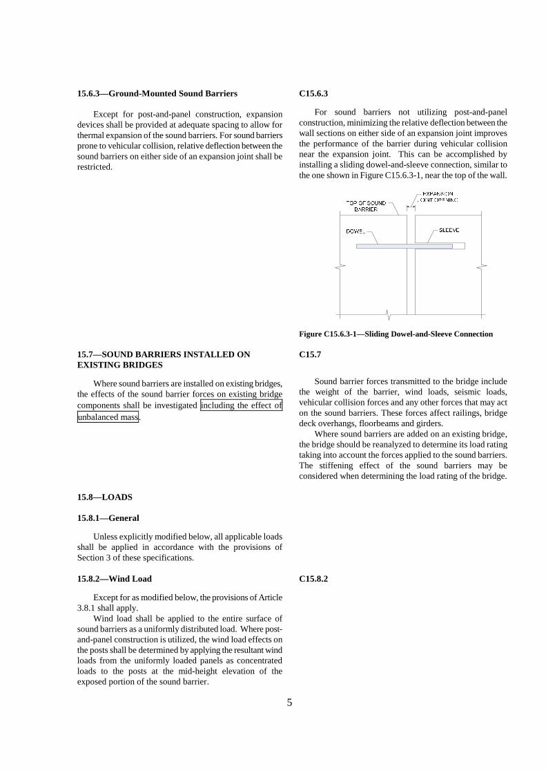
15.6.3—Ground-Mounted Sound Barriers
Except for post-and-panel construction, expansiondevices shall be provided at adequate spacing to allow forthermal expansion of the sound barriers. For sound barriersprone to vehicular collision, relative deflection between thesound barriers on either side of an expansion joint shall berestricted.
C15.6.3
For sound barriers not utilizing post-and-panelconstruction, minimizing the relative deflection between thewall sections on either side of an expansion joint improvesthe performance of the barrier during vehicular collisionnear the expansion joint. This can be accomplished byinstalling a sliding dowel-and-sleeve connection, similar tothe one shown in Figure C15.6.3-1, near the top of the wall.
Figure C15.6.3-1—Sliding Dowel-and-Sleeve Connection
15.7—SOUND BARRIERS INSTALLED ONEXISTING BRIDGES
Where sound barriers are installed on existing bridges,the effects of the sound barrier forces on existing bridge
components shall be investigated including the effect of
unbalanced mass.
C15.7
Sound barrier forces transmitted to the bridge includethe weight of the barrier, wind loads, seismic loads,vehicular collision forces and any other forces that may acton the sound barriers. These forces affect railings, bridgedeck overhangs, floorbeams and girders.
Where sound barriers are added on an existing bridge,the bridge should be reanalyzed to determine its load ratingtaking into account the forces applied to the sound barriers.The stiffening effect of the sound barriers may beconsidered when determining the load rating of the bridge.
15.8—LOADS
15.8.1—General
Unless explicitly modified below, all applicable loadsshall be applied in accordance with the provisions ofSection 3 of these specifications.
15.8.2—Wind Load
Except for as modified below, the provisions of Article3.8.1 shall apply.
Wind load shall be applied to the entire surface ofsound barriers as a uniformly distributed load. Where post-and-panel construction is utilized, the wind load effects onthe posts shall be determined by applying the resultant windloads from the uniformly loaded panels as concentratedloads to the posts at the mid-height elevation of theexposed portion of the sound barrier.
C15.8.2

6
For sound barriers, wind velocity at 30.0 ft above lowground or above design water level, V30, shall be taken as1.07 times the wind velocity at the sound barrier locationdetermined from Figure 15.8.2-1.
The wind velocities in Figure 15.8.2-1 have a 50 yearreturn period. The 1.07 multiplier is meant to convert thewind speed return period from the 50 years that Figure15.8.2-1 is based on to 75 year return period to be consistentwith the design life span assumed in these specifications.
For sound barriers, the factors Vo and Zo shall be takenfrom Table 15.8.2-1.
The Guide Specifications for Structural Design ofSound Barriers (1989) included four upstream surfaceconditions; B1, B2, C and D. Based on a limited study byWashington State Department of Transportation (2006).Upstream Surface Conditions B1 and C are approximatelyequivalent to the Suburban and Country upstream surfaceconditions shown in Table 3.8.1.1-1 and described in ArticleC3.8.1.1. The description of these categories is repeatedbelow. Table 15.8.2-1 includes two upstream surfaceconditions, designated as Sparse Suburban and Coastal thatdo not exist in Table 3.8.1.1-1. The values of the V0 and Z0
variables for these two upstream surface conditions wereselected to yield wind pressures approximately equal tothose obtained for Upstream Surface Conditions B2 and Din the Guide Specifications for Structural Design of SoundBarriers (1989).
Coastal— Flat unobstructed areas and water surfacesdirectly exposed to wind. This category includes largebodies of water, smooth mud flats, salt flats, andunbroken ice.
Open Country—Open terrain with scatteredobstructions having heights generally less than 30.0 ft.This category includes flat open country and grasslands.
Sparse Suburban— Areas with fewer obstructions thandescribed for Suburban conditions below but still morethan described for Open Country conditions above.
Suburban—Urban and suburban areas, wooded areas,or other terrain with numerous closely spacedobstructions having the size of single-family or largerdwellings. Use of this category shall be limited to thoseareas for which representative terrain prevails in theupwind direction at least 1,500 ft.
City—Large city centers with at least 50 percent of thebuildings having a height in excess of 70.0 ft. Use ofthis category shall be limited to those areas for whichrepresentative terrain prevails in the upwind direction atleast one-half mile. Possible channeling effects ofincreased velocity pressures due to the bridge orstructure’s location in the wake of adjacent structuresshall be taken into account.
Wind loads on structure-mounted sound barrierslocated in areas that can be characterized as City,Suburban, Sparse Suburban and Open Country shall bedetermined using the values for V0 and Zo specified forOpen Country conditions in Table 15.8.2-1.
Typically, the collapse of structure-mounted soundbarriers poses higher danger to life and property thanground-mounted sound barriers. Therefore, in areas withlow wind pressure, structure-mounted sound barriers aredesigned to a higher minimum wind load than ground-mounted sound barriers having the same upwind surfacecharacteristics. This is accomplished by designingstructure-mounted sound barriers to Open Countryconditions as a minimum.

7
Table 15.8.2-1—Values of V0 and Z0 for Various Upstream Surface Conditions
Condition Coastal Open CountrySparse
Suburban Suburban CityV0 (mph) 7 8.20 9.4 10.90 12.00
Z0 (ft.) 0.025 0.23 0.98 3.28 8.20

8
Figure 15.8.2-1—Isotach .02 quantiles, in miles per hour: Annual extreme-mile 30.0 ft. above ground, 50 years meanrecurrence intervals

9
15.8.3—Seismic Load
The provisions of Article 3.10 shall apply.For the design of the sound barrier wall panels, seismic
loads shall be applied to the entire elevation area of thesound barriers as a uniformly distributed lateral load.Where post-and-panel construction is utilized, in lieu of amore refined analysis, seismic loads shall be applied to theposts at a point located no less than 0.7 the exposed heightof the wall panels measured from the base of the panels.For the purpose of determining the point of application ofseismic loads on the posts, the base of the panels shall betaken as:
For ground-mounted sound barriers: the groundsurface adjacent to sound barrier, and
For structure-mounted sound barriers: the bottom ofthe lowest wall panel
C15.8.3
The point of application of seismic loads may becalculated by dividing the post base moment by the postbase shear. Trial analysis of a limited number of post-and-panel sound barrier systems that are 10.0 and 20.0 ft. highand are constructed in highly active seismic zones indicatedthat the location of the point of application of the seismicload on the posts, measured from the bottom of the wall,varied between 0.62 and 0.72 the wall height. A distance of0.7 the wall height was selected to result in a force effectclose to the upper bound observed in the study.
15.8.4—Earth Load
The provisions of Article 3.11 shall apply.
C15.8.4
Article 3.11.5.10 contains specific requirements for thedetermination of earth pressure on sound barrier foundationscomponents.
The possibility of difference between the actualfinished grade and that shown on the contract documentsshould be considered in the design.
Soil build up against sound barriers have been observedin some locations. Owners may determine the earth loadsfor the worst load case assuming an allowance in thefinished grade elevation.
15.8.5—Vehicular Collision Forces C15.8.5
Sound barrier systems, consisting of a traffic railingand a sound barrier, that have been successfully crash-tested may be used with no further analysis.
The depth of aesthetic treatments into the traffic face ofsound barrier that may be subjected to vehicular collisionshall be kept to a minimum.
Minimizing the depth of aesthetic treatment into thetraffic face of sound barriers that may be in contact with avehicle during a collision reduces the possibility of vehiclesnagging.
Sound barrier materials shall be selected to limitshattering of the sound barrier during vehicular collision.
Sound barrier systems may contain sacrificialcomponents or components that could need repair aftervehicular collision. Limiting shattering of sound barriers isparticularly important for sound barriers mounted on bridgescrossing over other traffic. When reinforced concretepanels are utilized for structure-mounted sound barriers, it isrecommended that two mats of reinforcement are used toreduce the possibility of the concrete shattering duringvehicular collision. Restraint cables placed in the middle ofconcrete panels may be used to reduce shattering whileavoiding the increased panel thickness required toaccommodate two layers of reinforcement.
The bridge overhang or moment slabs need not to bedesigned for more force effects than the resistance of thebase connection of the sound barrier.
In lieu of crash-testing, the resistance of componentsand connections to Extreme Event II force effects may be
The design strategy involving a controlled failurescenario is similar in concept to the use of capacity

10
determined based on a controlled failure scenario with aload path and sacrificial elements selected to assuredesirable performance of a structural system containing thesoundwall. Vehicular collision forces shall be applied tosound barriers located within the clear zone as follows:
Case 1: For sound barriers on a crashworthy traffic railingand for sound barriers mounted behind acrashworthy traffic railing with a sound barriersetback no more than 1.0 ft.: vehicular collisionforces specified in Section 13 shall be applied tothe sound barrier at a point 4.0 ft. above thesurface of the pavement in front of the trafficrailing for Test Levels 3 and lower and 6.0 ft.above the surface of the pavement in front of thetraffic railing for Test Levels 4 and higher.
Case 2: For sound barriers behind a crashworthy trafficrailing with a sound barrier setback of 4.0 ft.:vehicular collision force of 4.0 kips shall beapplied. The collision force shall be assumed toact at a point 4.0 ft. above the surface of thepavement in front of the traffic railing for TestLevels 3 and lower and 14.0 ft. above the surfaceof the pavement in front of the traffic railing forTest Levels 4 and higher.
Case 3: For sound barriers behind a crashworthy trafficrailing with a sound barrier setback between 1.0ft. and 4.0 ft.: vehicular collision forces and thepoint of application of the force shall vary linearlybetween their values and locations specified inCase 1 and Case 2 above.
Case 4: For sound barriers behind a crashworthy trafficrailing with a sound barrier setback more than 4.0ft.: vehicular collision forces need not beconsidered.
protected design to resist seismic forces. Some damage tothe soundwall, traffic barrier, or connections is oftenpreferable to designing an overhang or moment slab forforce effects due to vehicular collision. The bridge overhangor moment slabs need not be designed for more force effectsthan the resistance of the base connection of the soundbarriers.
Some guidance on desirable structural performance of
sound barriers can be found in European Standard
EN1794-2 (2003).
Very limited information is available on crash-testing ofsound barrier systems. The requirements of this article,including the magnitude of collision forces, are mostlybased on engineering judgment and observations madeduring crash-testing of traffic railings without soundbarriers.
In the absence of crash test results for sound barriersystems, sound barriers that have not been crash-tested areoften used in conjunction with vehicular railings that havebeen crash-tested as stand-alone railings, i.e. without soundbarriers. The collision forces specified herein are meant tobe applied to the sound barriers portion of such systems.
Crash Test Levels 3 and lower are performed usingsmall automobiles and pick-up trucks. Crash Test Levels 4and higher include single unit and/or tractor trailer trucks.The difference in height of the two groups of vehicles is thereason the location of the collision force is different for thetwo groups of sound barriers.
For crash Test Levels 3 and lower, the point ofapplication of the collision force on the sound barriers isassumed to be always 4.0 ft. above the pavement.
During crash-testing of traffic railings for crash TestLevel 4 and higher, trucks tend to tilt above the top of therailing and the top of the truck cargo box may reachapproximately 4.0 ft. behind the traffic face of the trafficrailing. For such systems, the point of application of thecollision force is expected to be as high as the height of thecargo box of a truck, assumed to be 14.0 ft. above thepavement surface.
For sound barriers mounted on crashworthy trafficbarriers or with a small setback, assumed to be less than 1.0ft., the full crash force is expected to act on the soundbarrier. The point of application of this force is assumed tobe at the level of the cargo bed; taken as 6.0 ft. above thesurface of the pavement.
For a sound barrier mounted with a setback more than1.0 ft. behind the traffic face of the traffic railing, it isexpected that the truck cargo box, not the cargo bed, willimpact the sound barrier. It is expected that the top of thecargo box will touch the sound barrier first. Due to the softconstruction of cargo boxes, it is assumed that they will becrushed and will soften the collision with the sound barrier.The depth of the crushed area will increase with the increaseof the collision force; thus lowering the location of theresultant of the collision force. The magnitude of thecollision force and the degree to which the cargo box iscrushed are expected to decrease as the setback of the soundbarrier increases.

11
In the absence of test results, it is assumed that acollision force of 4.0 kips will develop at the top of thecargo box when it impacts sound barriers mounted with asetback of 4.0 ft.
The collision force and the point of application areassumed to vary linearly as the sound barrier setback variesbetween 1.0 ft. and 4.0 ft.
The setback of the sound barrier, S, shall be taken asshown in Figure 15.8.5-1.
Figure 15.8.5-1—Sound Barrier Setback Distance
Collision forces on sound barriers shall be applied as aline load with a length equal to the longitudinal length ofdistribution of collision forces, Lt, specified in Article A13.
For sound barriers prone to vehicular collision forces,the wall panels and posts and the post connections to thesupporting traffic barriers or footings shall be designed toresist the vehicular collision forces at the Extreme Event IIlimit state.
For post-and-panel construction, the design collisionforce for the wall panels shall be the full specified collisionforce placed on one panel between two posts at the locationthat maximizes the load effect being checked. For postsand post connections to the supporting components, thedesign collision force shall be the full specified collisionforce applied at the point of application specified in Cases 1through 3 above.
The vehicular railing part of the sound barrier/railingsystem does not need to satisfy any additional requirementsbeyond the requirements specified in Section 13 of thespecifications for the stand-alone railings; including theheight and resistance requirements.
In some cases the wall panel is divided into a series ofhorizontal elements. In these situations, each horizontalstrip should be designed for the full design force.
Unless otherwise specified by the Owner, vehicularcollision forces shall be considered in the design of soundbarriers.
Owners may select to ignore vehicular collision forcesin the design of sound barriers at locations where thecollapse of the sound barrier, or portions of thereof, hasminimal safety consequences.

12
15.9—FOUNDATION DESIGN
15.9.1—General
Unless otherwise specified by the Owner, thegeotechnical resistance of materials supporting soundbarrier foundations shall be estimated using the procedurespresented in Article 10.6 for spread footings, 10.7 fordriven piles, and 10.8 for drilled shafts.
C15.9.1
Although sound barriers may be supported on spreadfooting or driven pile foundations, drilled shafts are morecommonly used because drilled shafts facilitate controllingthe vertical alignment of sound barrier structural wallsupports and the lateral spacing between them.
15.9.2—Determination of Soil and Rock Properties
The provisions of Articles 2.4 and 10.4 shall apply.
15.9.3—Limit States
Sound barriers shall be designed to withstand lateralwind and earth pressures, self weight of the wall, vehicularcollision loads, and earthquake loads in accordance with thegeneral principles specified in this section and Sections 10and 11.
Sound barriers shall be investigated for vertical andlateral displacement, and overall stability at the Service ILimit State. Tolerable deformation criteria shall bedeveloped based on maintaining the required barrierfunctionality, achieving the anticipated service life, and theconsequences of unacceptable movements.
Sound barrier foundations shall be investigated at thestrength limit states using Eq. 1.3.2.1-1 for:
Bearing-resistance failure Overall stability, and
Structural failure.
Sound barrier foundations shall be investigated at theextreme event limit states using the applicable loadcombinations and load factors specified in Table 3.4.1-1.
15.9.4—Resistance Requirements
The factored resistance, RR, calculated for eachapplicable limit state shall be the nominal resistance, Rn,multiplied by an appropriate resistance factor, , specifiedin Articles 10.5.5.1, 10.5.5.2, 10.5.5.3, 11.5.6 or 11.5.7.
C15.9.4
Procedures for calculating nominal geotechnicalresistance of footings, driven piles, and drilled shafts areprovided in Articles 10.6, 10.7 and 10.8. These methodsare generally accepted for barriers supported on spreadfootings or footings on two or more rows of driven piles ordrilled shafts. The nominal geotechnical resistance of asingle row of driven piles or drilled shafts, or by acontinuous embedded foundation wall (commonly referredto as a “trench footing”), is more appropriately calculatedusing the provisions in Article 11.8 for nongravitycantilever walls.
Procedures for calculating nominal structuralresistance for concrete and steel components are providedin Sections 5 and 6.

13
15.9.5—Resistance Factors
The resistance factors for geotechnical design offoundations shall be as specified in Table 10.5.5.2.2.-1 forspread footing foundations, Table 10.5.5.2.3-1 for drivenpile foundations, Table 10.5.5.2.4-1 for drilled shaftfoundations, and Table 11.5.6-1 for permanent retainingwalls.
If methods other than those prescribed in theseSpecifications are used to estimate geotechnical resistance,are used, the resistance factors chosen shall provide equalor greater reliability than those given in Tables 10.5.5.2.2-1, 10.5.5.2.3-1, 10.5.5.2.4-1, and 11.5.6-1.
15.9.6—Loading
The provisions of Section 3, as modified by Article15.8, shall apply.
15.9.7—Movement and Stability at the Service LimitState
15.9.7.1—Movement
The provisions of Articles 10.6.2, 10.7.2, 10.8.2, or11.8.3, as appropriate, shall apply.
15.9.7.2—Overall Stability
The provisions of Article 11.6.2.3 shall apply.
15.9.8—Safety Against Geotechnical Failure at theStrength Limit State
Spread footings or footings supported on two or morerows of driven piles or drilled shafts shall be designed inaccordance with the provisions of Articles 10.6.3, 10.7.3 or10.8.3, respectively.
Footings supported on a single row of driven piles ordrilled shafts or on a continuous embedded foundation wall(“trench footing”) shall be designed in accordance with theprovisions of 11.8.4 using the earth pressure diagramsprovided in Article 3.11.5.10.
15.9.9—Seismic Design
The effect of earthquake loading shall be investigatedusing the Extreme Event I limit state of Table 3.4.1-1 withload factor p = 1.0, and an accepted methodology.
15.9.10—Corrosion Protection
The provisions of Article 11.8.7 shall apply.
15.9.11—Drainage
Where sound barriers support earth loads or canimpede water flow, the provisions of Article 11.8.8 shallapply.

14
REFERENCES
AASHTO. 1989. Guide Specifications for Structural Design of Sound Barriers. American Association of State Highwayand Transportation Officials, Washington, DC.
Bullard, Jr. D., L., Sheikh, N., M., Bligh, R., P., Haug, R., R., Schutt, J., R., and Storey, B., J. 2006. , AestheticConcrete Barrier Design, NCHRP Report 554. Transportation Research Board, National Research Council,Washington, DC.
Washington State Department of Transportation. 2006. Wind Loading Comparison. Washington State Department ofTransportation, Olympia, Washington.
White, M., Jewell, J., and Peter, R., Crash Testing of Various Textured Barriers, FHWA/CA/TL-2002/03. CaliforniaDepartment of Transportation, Sacramento, California, September 2002.

15
Agenda Item 48 (WAI 41)
Attachment B
Additions to Section 3New Article 3.11.5.10

16
3.11.5.10—Lateral Earth Pressures for SoundBarriers Supported on Discrete and ContinuousVertical Embedded Elements
For sound barriers supported on discrete vertical wallelements embedded in granular soil, rock, or cohesive soil,the simplified lateral earth pressure distributions shown inFigures 3.11.5.10-1, 3.11.5.10-2, and 3.11.5.10-3,respectively, may be used. For sound barriers supported oncontinuous vertical elements embedded in granular soil orcohesive soil, the simplified earth pressure distributionsshown in Figures 3.11.5.10-4 and 3.11.5.10-5,respectively, may be used. For sound barriers supported onretaining walls, the applicable provisions of Section 11shall apply.
C3.11.5.10
Earth pressure on foundations of sound barriers issimilar to that on nongravity retaining walls discussed inArticle 3.11.5.6 except that the soil elevation on both sidesof the wall is often the same or, if there is a difference,does not reach the top of the wall on one side. Theprovisions of this article are applicable to the foundationsof any wall that is not primarily intended to retain earth,i.e. there is no or little difference in the elevation of fill oneither side of the wall.
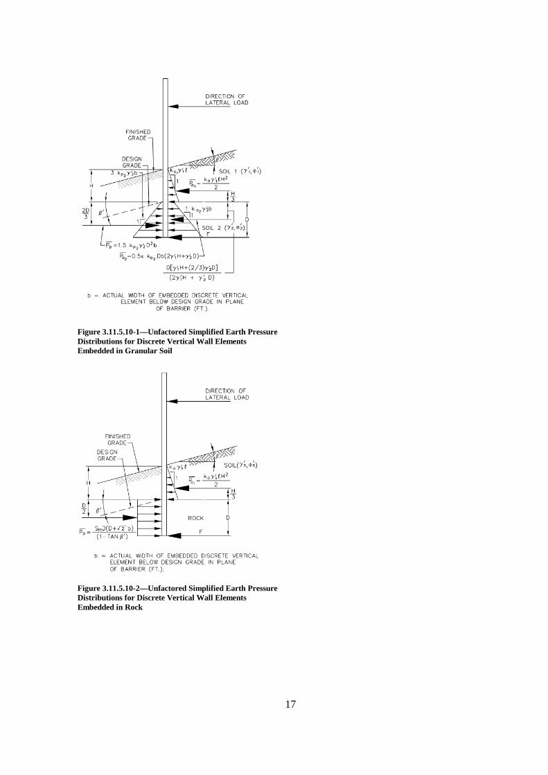
Where discrete vertical elements are used for support,the width, b, of each vertical element shall be assumed toequal the width of the flange or diameter of the element fordriven sections and the diameter of the concrete-filled holefor sections encased in concrete.
In Figures 3.11.5.10-1 and 3.11.5.10-3, the width, b,of discrete vertical elements effective in mobilizing thepassive resistance of the soil is based on a method ofanalysis by Broms (1964a, 1964b) for single vertical pilesembedded in cohesive or granular soil. Additionalinformation on the background of the earth pressure ondiscrete vertical elements is presented in Article C3.11.5.6.
The reversal in the direction of applied lateral forceson sound barriers shall be considered in the design.
The main applied lateral forces on sound barriers arewind and seismic forces; both of them are reversible.When the ground surface in front and/or behind the soundbarrier is not flat or the ground surface is not at the sameelevation on both sides of the sound barrier, the designshould be checked assuming that the lateral force is appliedin either direction. The effect of the direction of groundsurface slope, i.e. toward the barrier or away from thebarrier should be considered in earth pressure calculationsfor both directions of lateral loads. The earth pressurediagrams shown in Figures 3.11.5.10-1 through 3.11.5.10-5 correspond to the lateral load direction shown in thesefigures.
17
Figure 3.11.5.10-1—Unfactored Simplified Earth PressureDistributions for Discrete Vertical Wall ElementsEmbedded in Granular Soil
Figure 3.11.5.10-2—Unfactored Simplified Earth PressureDistributions for Discrete Vertical Wall ElementsEmbedded in Rock

18
Figure 3.11.5.10-3—Unfactored Simplified Earth PressureDistributions for Discrete Vertical Wall ElementsEmbedded in Cohesive Soil
Figure 3.11.5.10-4—Unfactored Simplified Earth PressureDistributions for Continuous Vertical Elements Embeddedin Granular Soil Modified After Teng (1962)

19
Figure 3.11.5.10-5—Unfactored Simplified Earth PressureDistributions for Continuous Vertical Wall ElementsEmbedded in Cohesive Soil Modified After Teng (1962)
20
Agenda Item 48 (WAI 41)
Attachment C
Revisions to existing Articles 3.8.1.1 and 3.8.1.2.1

21
3.8—WIND LOAD: WL AND WS
3.8.1—Horizontal Wind Pressure
3.8.1.1—General
Pressures specified herein shall be assumed to becaused by a base design wind velocity, VB, of 100 mph.
Wind load shall be assumed to be uniformlydistributed on the area exposed to the wind. The exposedarea shall be the sum of areas of all components, includingfloor system, railing and sound barriers, as seen inelevation taken perpendicular to the assumed winddirection. This direction shall be varied to determine theextreme force effect in the structure or in its components.Areas that do not contribute to the extreme force effectunder consideration may be neglected in the analysis.
For bridges or parts of bridges and sound barriersmore than 30.0 ft. above low ground or water level, thedesign wind velocity, VDZ, should be adjusted according to:
2.5 ln30DZ 0
B 0
V ZV V
V Z
(3.8.1.1-1)
where:
VDZ = design wind velocity at design elevation, Z (mph)
V30 = wind velocity at 30.0 ft. above low ground orabove design water level (mph)
VB = base wind velocity of 100 mph at 30.0 ft. height,yielding design pressures specified in Articles
3.8.1.2 and 3.8.2 3.8.1.2.1 and 3.8.1.2.2
Z = height of structure at which wind loads are beingcalculated as measured from low ground, or fromwater level, > 30.0 ft.
V0 = friction velocity, a meteorological windcharacteristic taken, as specified in Table 3.8.1.1-1, for various upwind surface characteristics(mph)
Z0 = friction length of upstream fetch, ameteorological wind characteristic taken asspecified in Table 3.8.1.1-1 (ft.)
C3.8.1.1
Base design wind velocity varies significantly due tolocal conditions. For small and/or low structures, windusually does not govern. For large and/or tall bridges andsound barriers, however, the local conditions should beinvestigated.
Pressures on windward and leeward sides are to betaken simultaneously in the assumed direction of wind.
Typically, a bridge structure should be examinedseparately under wind pressures from two or more differentdirections in order to ascertain those windward, leeward,and side pressures producing the most critical loads on thestructure.
Eq. 3.8.1.1-1 is based on boundary layer theorycombined with empirical observations and represents themost recent approach to defining wind speeds for variousconditions as used in meteorology. In the past, anexponential equation was sometimes used to relate windspeed to heights above 30.0 ft. This formulation was basedsolely on empirical observations and had no theoreticalbasis.
30DZ 30
ZV CV
(C3.8.1.1-1)
The purpose of the term C and exponent α was to adjust the equation for various upstream surface conditions,similar to the use of Table 3.8.1.1-1. Further informationcan be found in Liu (1991) and Simiu (1973, 1976).
The following descriptions for the terms “opencountry,” “suburban,” and “city” in Table 3.8.1.1-1 areparaphrased from ASCE-7-93:
Open Country—Open terrain with scatteredobstructions having heights generally less than30.0 ft. This category includes flat open countryand grasslands.
Suburban—Urban and suburban areas, woodedareas, or other terrain with numerous closelyspaced obstructions having the size of single-family or larger dwellings. Use of this categoryshall be limited to those areas for whichrepresentative terrain prevails in the upwinddirection at least 1,500 ft.

22
City—Large city centers with at least 50 percentof the buildings having a height in excess of 70.0ft. Use of this category shall be limited to thoseareas for which representative terrain prevails inthe upwind direction at least one-half mile.Possible channeling effects of increased velocitypressures due to the bridge or structure’s locationin the wake of adjacent structures shall be takeninto account.
Table 3.8.1.1-1—Values of V0 and Z0 for Various UpstreamSurface Conditions
CONDITIONOPEN
COUNTRY SUBURBAN CITYV0 (mph) 8.20 10.90 12.00Z0 (ft.) 0.23 3.28 8.20
Except for sound barriers, V30 may be establishedfrom:
Fastest-mile-of-wind charts available in ASCE 7-88for various recurrence intervals,
Site-specific wind surveys, and
In the absence of better criterion, the assumption thatV30 = VB = 100 mph.
For Sound Barriers, V30 shall be taken as specified inArticle 15.8.2.
3.8.1.2—Wind Pressure on Structures: WS
3.8.1.2.1—General
If justified by local conditions, a different base designwind velocity may be selected for load combinations notinvolving wind on live load. The direction of the designwind shall be assumed to be horizontal, unless otherwisespecified in Article 3.8.3. In the absence of more precisedata, design wind pressure, in ksf, may be determined as:
2 2
10,000DZ DZ
D B B
B
V VP P P
V
(3.8.1.2.1-1)
PB = base wind pressure specified in Table 3.8.1.2.1-1(ksf)
C3.8.1.2.1
The stagnation pressure associated with a windvelocity of 100 mph is 0.0256 ksf, which is significantlyless than the values specified in Table 3.8.1.2.1-1. Thedifference reflects the effect of gusting combined withsome tradition of long-time usage.
The pressures specified in klf or ksf should bechosen to produce the greater net wind load on thestructure.
Wind tunnel tests may be used to provide moreprecise estimates of wind pressures. Such testing shouldbe considered where wind is a major design load.
The wind force on the structure shall be calculated bymultiplying the design wind pressure, PD, calculated usingEq. 3.8.1.2.1-1, by the exposed area, including the area ofsound barriers, if existing, regardless of the design windpressure used in designing the sound barriers themselves.
…..NO OTHER REVISIONS TO END OFARTICLE…..
Due to the lack of information on the wind force onsound barriers, the wind pressure specified in Article15.8.2 for the design of sound barriers is based onproducing similar wind pressures to those used for thedesign of sound barrier under the AASHTO (1989).Such values of wind pressures proved to produce safedesigns in the past…..NO OTHER REVISIONS TO

23
END OF ARTICLE…..
3.8.1.2.2—Loads from Superstructures
Except where specified herein, where the wind is nottaken as normal to the structure, the base wind pressures,PB, for various angles of wind direction may be taken asspecified in Table 3.8.1.2.2-1 and shall be applied to thecentroid of a single plane of exposed area. The skew angleshall be taken as measured from a perpendicular to thelongitudinal axis. The wind direction for design shall bethat which produces the extreme force effect on thecomponent under investigation. The transverse andlongitudinal pressures shall be applied simultaneously.
C3.8.1.2.2
For trusses, columns, and arches, the base windpressures specified in Table 3.8.1.2.2-1 are the sum ofthe pressures applied to both the windward and leewardareas.
Table 3.8.1.2.2-1—Base Wind Pressures, PB, for Various Angles of Attack and VB = 100 mph
Skew Angle of Wind(degrees)
Trusses,Columns and Arches Girders
Lateral Load(ksf)
Longitudinal Load(ksf)
Lateral Load(ksf)
Longitudinal Load(ksf)
0 0.075 0.000 0.050 0.00015 0.070 0.012 0.044 0.00630 0.065 0.028 0.041 0.012
45 0.047 0.041 0.033 0.01660 0.024 0.050 0.017 0.019
For the usual girder and slab bridges having anindividual span length of not more than 125 ft and amaximum height of 30.0 ft above low ground or waterlevel the following wind loading may be used:
0.05 ksf, transverse
0.012 ksf, longitudinal
Both forces shall be applied simultaneously. Theseforces shall not be used in determining the forces on soundbarriers.
Wind pressure on sound barriers should bedetermined using the provisions of Article 15.8.2.
Add the following Reference to Section 3 of AASHTO LRFD:
AASHTO. 1989. Guide Specifications for Structural Design of Sound Barriers. American Association of State Highwayand Transportation Officials, Washington, DC.