Embed Size (px)
Citation preview
MCE WAREHOUSE RENOVATION CONTRACT NO. MCE-000-160-C01
REQUEST FOR PROPOSAL DESIGN/BUILD CONSTRUCTION
ATTACHMENT 1
MCE WAREHOUSE CONCEPT DRAWINGS
MCE WAREHOUSE RENOVATION CONTRACT NO. MCE-000-160-C01
REQUEST FOR PROPOSAL DESIGN/BUILD CONSTRUCTION
ATTACHMENT 2
SPECIFICATIONS
2-1. High Performance Coating
2-2. Fixed Aluminum Window
2-3. Electronic Security System
MCE WAREHOUSE RENOVATION CONTRACT NO. MCE-000-160-C01
REQUEST FOR PROPOSAL DESIGN/BUILD CONSTRUCTION
ATTACHMENT 3
MCE WAREHOUSE SALVAGED DRAWINGS
MCE WAREHOUSE RENOVATION CONTRACT NO. MCE-000-160-C01
REQUEST FOR PROPOSAL DESIGN/BUILD CONSTRUCTION
ATTACHMENT 4
MCE WAREHOUSE HAZMAT SURVEY
SECTION 09 96 00 HIGH PERFORMANCE COATINGS MCE Warehouse Renovation, Jessup MD
PART 1 - GENERAL
1.1 GENERAL REQUIREMENTS
A. Work of this section as shown or specified shall be in accordance with the requirements of the Contract Documents.
1.2 WORK INCLUDED
A. Work of this section includes all labor, materials, equipment and services necessary to complete epoxy flooring incorporating ceramic coated colored inorganic quartz aggregate and integral base as selected on drawings and/or specified herein. Contractor to include an allowance of $ 20,000 in their bid for testing and inspection services for this part of the scope.
1.3 RELATED SECTIONS
A. Section 03 30 00 – Concrete: To be water cured or cured suing sodium silicate curing compound.
B. Section 09 91 00 – Painting
C. Division 15 – Floor Drains: Flange type.
1.4 REFERENCES
A. Society for Protective Coatings (SSPC) Specifications and Standards.
1. SSPC-PA-3: “A Guide to Safety in Paint Application”. 2. SSPC-SP-13: “Surface Preparation of Concrete”.
B. NACE (National Association of Corrosion Engineers)
1. NACE Publication 6D-173, “A Manual for Painter Safety”. 2. NACE Publication 6G-164, “Surface Preparation Abrasives for Industrial Maintenance Painting”.
C. ASTM (American Society for Testing and Materials)
1. ASTM D4541 - L.R. “Standard Method for Pull-Off Strength of Coatings using Portable Adhesion Testers”.
2. ASTM E337 - L.R. “Standard Practice Test Method for Measuring Humidity with a Psychrometer”.
3. ASTM D4263-83 (1999), “Standard Test Method for Indicating Moisture in Concrete by the Plastic Sheet Method”.
4. ASTM F1869-98, “Standard Test Method for Measuring Moisture Vapor Emission Rate of Concrete Subfloor Using Anhydrous Calcium Chloride”.
5. ASTM D4414-95, “Standard Practice for Measurement of Wet Film Thickness by Notched Gages”.
6. ICRI Guide No. 03732, “Selecting and Specifying Concrete Surface Preparation for Sealers, Coatings and Polymer Overlays,” International Concrete Repair Institute, Sterling, VA.
SECTION 09 96 00 Page 1 of 9 MCE Warehouse Renovation,
Jessup MD
SECTION 09 96 00 HIGH PERFORMANCE COATINGS MCE Warehouse Renovation, Jessup MD
7. ASTM 4262, “Standard Test Method for Measuring Surface pH of Acid Etched Concrete.” 8. ASTM D 522, Flexibility 9. ASTM D 579, Compressive Strength 10. ASTM D 580, Flexural Strength And Modulus Of Elasticity 11. ASTM D 790, Flexural Strength And Modulus Of Elasticity 13. ASTM D 2047, Coefficient Of Friction 14. ASTM D 2240, Hardness (Shore D Dorometer) 15. ASTM D 2794, Impact 16. ASTM D 3359, Adhesion 17. ASTM D 3363, Hardness 18. ASTM D 4060, Abrasion 19. ASTM D4259, “Standard Practice for Abrading Concrete
1.5 SUBMITTALS
A. General: Submit the following in accordance with Conditions of Contract and Division I Specification Sections. The contractor to engage a MD EPA approved testing firm to conduct a complete lead and
mold testing and submit a complete report identifying the areas, percentage of lead, work plan for removal and a detail schedule for review.
B. Product Data: Submit manufacturer’s technical data, application instructions, performance criteria and general recommendations for decorative epoxy flooring specified herein.
D. Samples for initial selection purposes in form of manufacturer’s color charts showing range of standard colors available.
1. Submit 2-1/2” x 4” samples in color and quartz aggregate combination as selected.
E. Material certificates signed by manufacturer certifying that the decorative quartz epoxy flooring submitted complies with the requirements specified herein.
F. Maintenance Instructions: Submit manufacturer’s written instructions for recommended maintenance practices.
1.6 QUALITY ASSURANCE
A. Installer Qualifications: Engage an experienced installer or applicator that has specialized in installing high performance coatings and resinous flooring types similar to that required for this project and who is acceptable to manufacturer of primary materials.
B. Single Source Responsibility: Obtain acrylic wall and ceiling coatings, and epoxy component of flooring materials, including primers, resins, hardening agents, and finish or sealing coats, from a single manufacturer.
1.7 DELIVERY STORAGE AND HANDLING
A. Deliver materials in original packages and containers with seals unbroken and bearing manufacturer’s labels containing brand name and directions for storage and mixing with other components.
B. Store materials to comply with manufacturer’s directions to prevent deterioration from moisture, heat,
SECTION 09 96 00 Page 2 of 9 MCE Warehouse Renovation,
Jessup MD
SECTION 09 96 00 HIGH PERFORMANCE COATINGS MCE Warehouse Renovation, Jessup MD
cold, direct sunlight, or other detrimental effects.
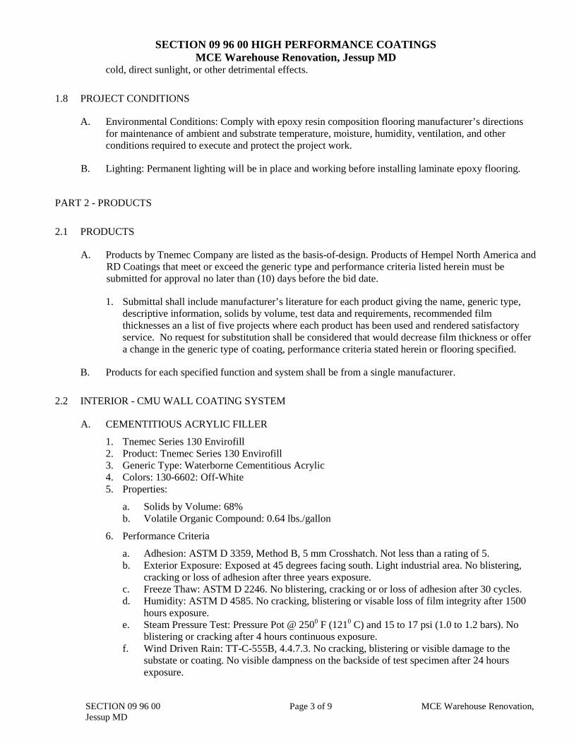
1.8 PROJECT CONDITIONS
A. Environmental Conditions: Comply with epoxy resin composition flooring manufacturer’s directions for maintenance of ambient and substrate temperature, moisture, humidity, ventilation, and other conditions required to execute and protect the project work.
B. Lighting: Permanent lighting will be in place and working before installing laminate epoxy flooring.
PART 2 - PRODUCTS
2.1 PRODUCTS
A. Products by Tnemec Company are listed as the basis-of-design. Products of Hempel North America and RD Coatings that meet or exceed the generic type and performance criteria listed herein must be submitted for approval no later than (10) days before the bid date.
1. Submittal shall include manufacturer’s literature for each product giving the name, generic type, descriptive information, solids by volume, test data and requirements, recommended film thicknesses an a list of five projects where each product has been used and rendered satisfactory service. No request for substitution shall be considered that would decrease film thickness or offer a change in the generic type of coating, performance criteria stated herein or flooring specified.
B. Products for each specified function and system shall be from a single manufacturer.
2.2 INTERIOR - CMU WALL COATING SYSTEM
A. CEMENTITIOUS ACRYLIC FILLER
1. Tnemec Series 130 Envirofill 2. Product: Tnemec Series 130 Envirofill 3. Generic Type: Waterborne Cementitious Acrylic 4. Colors: 130-6602: Off-White 5. Properties:
a. Solids by Volume: 68% b. Volatile Organic Compound: 0.64 lbs./gallon
6. Performance Criteria
a. Adhesion: ASTM D 3359, Method B, 5 mm Crosshatch. Not less than a rating of 5. b. Exterior Exposure: Exposed at 45 degrees facing south. Light industrial area. No blistering, cracking or loss of adhesion after three years exposure. c. Freeze Thaw: ASTM D 2246. No blistering, cracking or or loss of adhesion after 30 cycles. d. Humidity: ASTM D 4585. No cracking, blistering or visable loss of film integrity after 1500 hours exposure. e. Steam Pressure Test: Pressure Pot @ 2500 F (1210 C) and 15 to 17 psi (1.0 to 1.2 bars). No blistering or cracking after 4 hours continuous exposure.
f. Wind Driven Rain: TT-C-555B, 4.4.7.3. No cracking, blistering or visible damage to the substate or coating. No visible dampness on the backside of test specimen after 24 hours exposure.
SECTION 09 96 00 Page 3 of 9 MCE Warehouse Renovation,
Jessup MD
SECTION 09 96 00 HIGH PERFORMANCE COATINGS MCE Warehouse Renovation, Jessup MD
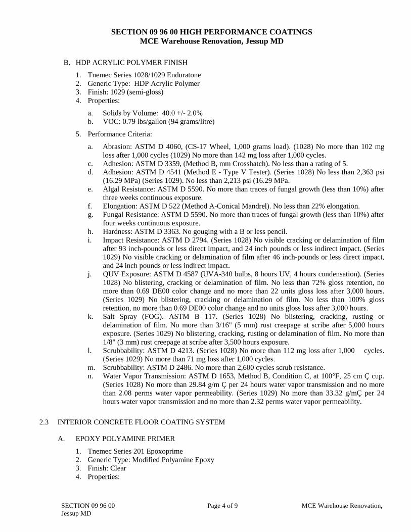
B. HDP ACRYLIC POLYMER FINISH
1. Tnemec Series 1028/1029 Enduratone 2. Generic Type: HDP Acrylic Polymer 3. Finish: 1029 (semi-gloss) 4. Properties:
a. Solids by Volume: 40.0 +/- 2.0% b. VOC: 0.79 lbs/gallon (94 grams/litre)
5. Performance Criteria:
a. Abrasion: ASTM D 4060, (CS-17 Wheel, 1,000 grams load). (1028) No more than 102 mg loss after 1,000 cycles (1029) No more than 142 mg loss after 1,000 cycles.
c. Adhesion: ASTM D 3359, (Method B, mm Crosshatch). No less than a rating of 5. d. Adhesion: ASTM D 4541 (Method E - Type V Tester). (Series 1028) No less than 2,363 psi
(16.29 MPa) (Series 1029). No less than 2,213 psi (16.29 MPa. e. Algal Resistance: ASTM D 5590. No more than traces of fungal growth (less than 10%) after
three weeks continuous exposure. f. Elongation: ASTM D 522 (Method A-Conical Mandrel). No less than 22% elongation. g. Fungal Resistance: ASTM D 5590. No more than traces of fungal growth (less than 10%) after
four weeks continuous exposure. h. Hardness: ASTM D 3363. No gouging with a B or less pencil. i. Impact Resistance: ASTM D 2794. (Series 1028) No visible cracking or delamination of film
after 93 inch-pounds or less direct impact, and 24 inch pounds or less indirect impact. (Series 1029) No visible cracking or delamination of film after 46 inch-pounds or less direct impact, and 24 inch pounds or less indirect impact.
j. QUV Exposure: ASTM D 4587 (UVA-340 bulbs, 8 hours UV, 4 hours condensation). (Series 1028) No blistering, cracking or delamination of film. No less than 72% gloss retention, no more than 0.69 DE00 color change and no more than 22 units gloss loss after 3,000 hours. (Series 1029) No blistering, cracking or delamination of film. No less than 100% gloss retention, no more than 0.69 DE00 color change and no units gloss loss after 3,000 hours.
k. Salt Spray (FOG). ASTM B 117. (Series 1028) No blistering, cracking, rusting or delamination of film. No more than 3/16" (5 mm) rust creepage at scribe after 5,000 hours exposure. (Series 1029) No blistering, cracking, rusting or delamination of film. No more than 1/8" (3 mm) rust creepage at scribe after 3,500 hours exposure.
l. Scrubbability: ASTM D 4213. (Series 1028) No more than 112 mg loss after 1,000 cycles. (Series 1029) No more than 71 mg loss after 1,000 cycles.
m. Scrubbability: ASTM D 2486. No more than 2,600 cycles scrub resistance. n. Water Vapor Transmission: ASTM D 1653, Method B, Condition C, at 100°F, 25 cm Ç cup.
(Series 1028) No more than 29.84 g/m Ç per 24 hours water vapor transmission and no more than 2.08 perms water vapor permeability. (Series 1029) No more than 33.32 g/mÇ per 24 hours water vapor transmission and no more than 2.32 perms water vapor permeability.
2.3 INTERIOR CONCRETE FLOOR COATING SYSTEM
A. EPOXY POLYAMINE PRIMER
1. Tnemec Series 201 Epoxoprime 2. Generic Type: Modified Polyamine Epoxy 3. Finish: Clear 4. Properties:
SECTION 09 96 00 Page 4 of 9 MCE Warehouse Renovation,
Jessup MD
SECTION 09 96 00 HIGH PERFORMANCE COATINGS MCE Warehouse Renovation, Jessup MD
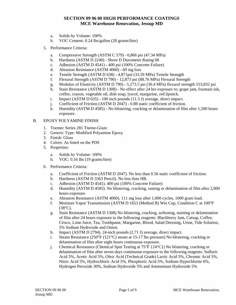
a. Solids by Volume: 100% b. VOC Content: 0.24 lbs/gallon (28 grams/litre)
5. Performance Criteria:
a. Compressive Strength (ASTM C 579) - 6,866 psi (47.34 MPa) b. Hardness (ASTM D 2240) - Shore D Durometer Rating 68 c. Adhesion (ASTM D 4541) - 400 psi (100% Concrete Failure) d. Abrasion Resistance (ASTM 4060) - 69 mg loss e. Tensile Strength (ASTM D 638) - 4,871psi (33.59 MPa) Tensile Strength f. Flexural Strength (ASTM D 790) - 12,873 psi (88.76 MPa) Flexural Strength g. Modulus of Elasticity (ASTM D 790) - 5,273.5 psi (36.4 MPa) flexural strength 553,832 psi
h. Stain Resistance (ASTM D 1308) - No effect after 24 hrs exposure to; grape jam, fountain ink, coffee, crayon, vegetable oil, dish soap, lyscol, margarine, red lipstick.
i. Impact (ASTM D 635) - 100 inch pounds (11.3 J) average, direct impact. j. Coefficient of Friction (ASTM D 2047) - 0.88 static coefficient of friction. k. Humidity (ASTM D 4585) - No blistering, cracking or delamination of film after 1,500 hours exposure.
B. EPOXY POLYAMINE FINISH
1. Tnemec Series 281 Tneme-Glaze 2. Generic Type: Modified Polyamine Epoxy 3. Finish: Gloss 4. Colors: As listed on the PDS 5. Properties:
a. Solids by Volume: 100% b. VOC: 0.16 lbs (19 grams/litre)
6. Performance Criteria:
a. Coefficient of Friction (ASTM D 2047). No less than 0.56 static coefficient of friction. b. Hardness (ASTM D 3363 Pencil). No less than HB. c. Adhesion (ASTM D 4541). 400 psi (100% Concrete Failure) d. Humidity (ASTM D 4585). No blistering, cracking, rusting or delamination of film after 2,000
hours exposure. e. Abrasion Resistance (ASTM 4060). 111 mg loss after 1,000 cycles, 1000 gram load. f. Moisture Vapor Transmission (ASTM D 1653 (Method B) Wet Cup, Condition C at 100°F
(38°C). g. Stain Resistance (ASTM D 1308) No blistering, cracking, softening, staining or delamination
of film after 24 hours exposure to the following reagents: Blackberry Jam, Catsup, Coffee, Crisco, Lime Juice, Tea, Toothpaste, Margarine, Blood, Salad Dressing, Urine, Tide Solution, 5% Sodium Hydroxide and Onion.
h. Impact (ASTM D 2794). 24-inch pounds (2.71 J) average, direct impact. i. Steam Resistance (250°F (121°C) steam at 15-17 lbs pressure) No blistering, cracking or
delamination of film after eight hours continuous exposure. j. Chemical Resistance (Chemical Spot Testing at 75°F {24°C}) No blistering, cracking or
delamination of film after seven days continuous exposure to the following reagents: Sulfuric Acid 5%, Acetic Acid 5%, Oleic Acid (Technical Grade) Lactic Acid 5%, Chromic Acid 5%, Nitric Acid 5%, Hydrochloric Acid 5%, Phosphoric Acid 5%, Sodium Hypochlorite 6%, Hydrogen Peroxide 30%, Sodium Hydroxide 5% and Ammonium Hydroxide 5%
SECTION 09 96 00 Page 5 of 9 MCE Warehouse Renovation,
Jessup MD
SECTION 09 96 00 HIGH PERFORMANCE COATINGS MCE Warehouse Renovation, Jessup MD
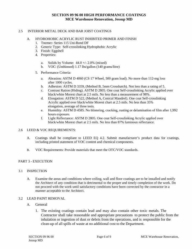
2.5 INTERIOR METAL DECK AND BAR JOIST COATINGS
A. HYDROHOBIC ACRYLIC RUST INHIBITED PRIMER AND FINISH 1. Tnemec- Series 115 Uni-Bond DF 2. Generic Type: Self-crosslinking Hydrophobic Acrylic 3. Finish: Eggshell 4. Properties: a. Solids by Volume: 44.0 +/- 2.0% (mixed) b. VOC: (Unthinned) 1.17 lbs/gallon (140 grams/litre)
5. Performance Criteria:
a. Abrasion: ASTM D 4060 (CS 17 Wheel, 500 gram load). No more than 112-mg loss after 1000 cycles. b. Adhesion: ASTM D 3359, (Method B, 5mm Crosshatch). Not less than a rating of 5. c. Contrast Ration (Hiding). ASTM D 2805. One coat Self-crosslinking Acrylic applied over black/white Morest chart at 2.5 mils. No less than a measurement of 98%. d. Elongation: ASTM D 522, (Method A, Conical Mandrel). One coat Self-crosslinking
Acrylic applied over black/white Morest chart at 2.5 mils. No less than 35% elongation, average of three tests. e. Humidity: ASTM D 4585. No blistering, cracking, rusting or delamination of film after 1,992
hours exposure. f. Light Reflectance: ASTM D 2805. One coat Self-crosslinking Acrylic applied over black/white Morest chart at 2.5 mils. No less than 87% luminous reflectance.
2.6 LEED & VOC REQUIREMENTS:
A. Coatings shall be compliant to LEED EQ 4.2. Submit manufacturer’s product data for coatings, including printed statement of VOC content and chemical components.
B. VOC Requirements: Provide materials that meet the OTC/VOC standards.
PART 3 - EXECUTION
3.1 INSPECTION
A. Examine the areas and conditions where ceiling, wall and floor coatings are to be installed and notify the Architect of any condition that is detrimental to the proper and timely completion of the work. Do not proceed with the work until satisfactory conditions have been corrected by the contractor in a manner acceptable to the Architect.
3.2 LEAD PAINT REMOVAL
A. General
1. The existing coatings contain lead and may also contain other toxic metals. The Contractor shall take reasonable and appropriate precautions to protect the public from the inhalation or ingestion of dust or debris from the operations, and is responsible for the clean-up of all spills of waste at no additional cost to the Department.
SECTION 09 96 00 Page 6 of 9 MCE Warehouse Renovation,
Jessup MD
SECTION 09 96 00 HIGH PERFORMANCE COATINGS MCE Warehouse Renovation, Jessup MD
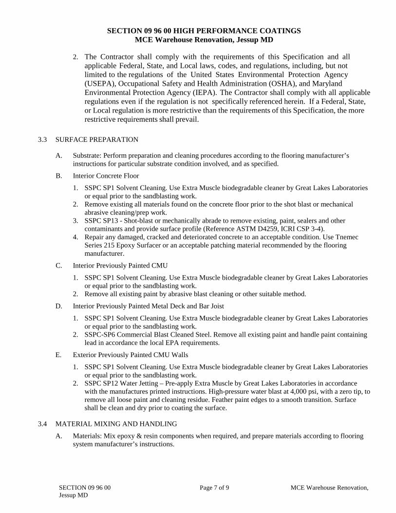
2. The Contractor shall comply with the requirements of this Specification and all
applicable Federal, State, and Local laws, codes, and regulations, including, but not limited to the regulations of the United States Environmental Protection Agency
(USEPA), Occupational Safety and Health Administration (OSHA), and Maryland Environmental Protection Agency (IEPA). The Contractor shall comply with all applicable regulations even if the regulation is not specifically referenced herein. If a Federal, State, or Local regulation is more restrictive than the requirements of this Specification, the more restrictive requirements shall prevail.
3.3 SURFACE PREPARATION
A. Substrate: Perform preparation and cleaning procedures according to the flooring manufacturer’s instructions for particular substrate condition involved, and as specified.
B. Interior Concrete Floor
1. SSPC SP1 Solvent Cleaning. Use Extra Muscle biodegradable cleaner by Great Lakes Laboratories or equal prior to the sandblasting work.
2. Remove existing all materials found on the concrete floor prior to the shot blast or mechanical abrasive cleaning/prep work.
3. SSPC SP13 - Shot-blast or mechanically abrade to remove existing, paint, sealers and other contaminants and provide surface profile (Reference ASTM D4259, ICRI CSP 3-4).
4. Repair any damaged, cracked and deteriorated concrete to an acceptable condition. Use Tnemec Series 215 Epoxy Surfacer or an acceptable patching material recommended by the flooring manufacturer.
C. Interior Previously Painted CMU
1. SSPC SP1 Solvent Cleaning. Use Extra Muscle biodegradable cleaner by Great Lakes Laboratories or equal prior to the sandblasting work.
2. Remove all existing paint by abrasive blast cleaning or other suitable method.
D. Interior Previously Painted Metal Deck and Bar Joist
1. SSPC SP1 Solvent Cleaning. Use Extra Muscle biodegradable cleaner by Great Lakes Laboratories or equal prior to the sandblasting work.
2. SSPC-SP6 Commercial Blast Cleaned Steel. Remove all existing paint and handle paint containing lead in accordance the local EPA requirements.
E. Exterior Previously Painted CMU Walls
1. SSPC SP1 Solvent Cleaning. Use Extra Muscle biodegradable cleaner by Great Lakes Laboratories or equal prior to the sandblasting work.
2. SSPC SP12 Water Jetting – Pre-apply Extra Muscle by Great Lakes Laboratories in accordance with the manufactures printed instructions. High-pressure water blast at 4,000 psi, with a zero tip, to remove all loose paint and cleaning residue. Feather paint edges to a smooth transition. Surface shall be clean and dry prior to coating the surface.
3.4 MATERIAL MIXING AND HANDLING
A. Materials: Mix epoxy & resin components when required, and prepare materials according to flooring system manufacturer’s instructions.
SECTION 09 96 00 Page 7 of 9 MCE Warehouse Renovation,
Jessup MD
SECTION 09 96 00 HIGH PERFORMANCE COATINGS MCE Warehouse Renovation, Jessup MD
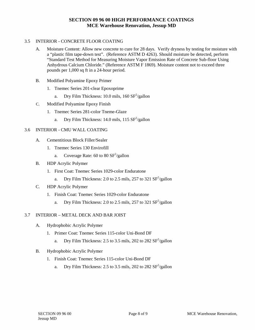
3.5 INTERIOR - CONCRETE FLOOR COATING
A. Moisture Content: Allow new concrete to cure for 28 days. Verify dryness by testing for moisture with a “plastic film tape-down test”. (Reference ASTM D 4263). Should moisture be detected, perform “Standard Test Method for Measuring Moisture Vapor Emission Rate of Concrete Sub-floor Using Anhydrous Calcium Chloride.” (Reference ASTM F 1869). Moisture content not to exceed three pounds per 1,000 sq ft in a 24-hour period.
B. Modified Polyamine Epoxy Primer
1. Tnemec Series 201-clear Epoxoprime
a. Dry Film Thickness: 10.0 mils, 160 SF2/gallon
C. Modified Polyamine Epoxy Finish
1. Tnemec Series 281-color Tneme-Glaze
a. Dry Film Thickness: 14.0 mils, 115 SF2/gallon
3.6 INTERIOR - CMU WALL COATING
A. Cementitious Block Filler/Sealer
1. Tnemec Series 130 Envirofill
a. Coverage Rate: 60 to 80 SF2/gallon
B. HDP Acrylic Polymer
1. First Coat: Tnemec Series 1029-color Enduratone
a. Dry Film Thickness: 2.0 to 2.5 mils, 257 to 321 SF2/gallon
C. HDP Acrylic Polymer
1. Finish Coat: Tnemec Series 1029-color Enduratone
a. Dry Film Thickness: 2.0 to 2.5 mils, 257 to 321 SF2/gallon
3.7 INTERIOR – METAL DECK AND BAR JOIST
A. Hydrophobic Acrylic Polymer
1. Primer Coat: Tnemec Series 115-color Uni-Bond DF
a. Dry Film Thickness: 2.5 to 3.5 mils, 202 to 282 SF2/gallon
B. Hydrophobic Acrylic Polymer
1. Finish Coat: Tnemec Series 115-color Uni-Bond DF
a. Dry Film Thickness: 2.5 to 3.5 mils, 202 to 282 SF2/gallon
SECTION 09 96 00 Page 8 of 9 MCE Warehouse Renovation,
Jessup MD
SECTION 09 96 00 HIGH PERFORMANCE COATINGS MCE Warehouse Renovation, Jessup MD
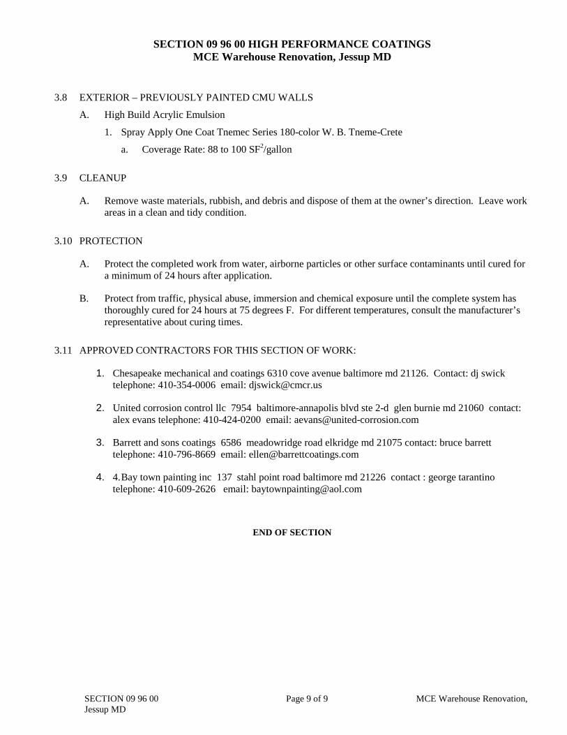
3.8 EXTERIOR – PREVIOUSLY PAINTED CMU WALLS
A. High Build Acrylic Emulsion
1. Spray Apply One Coat Tnemec Series 180-color W. B. Tneme-Crete
a. Coverage Rate: 88 to 100 SF2/gallon
3.9 CLEANUP
A. Remove waste materials, rubbish, and debris and dispose of them at the owner’s direction. Leave work areas in a clean and tidy condition.
3.10 PROTECTION
A. Protect the completed work from water, airborne particles or other surface contaminants until cured for a minimum of 24 hours after application.
B. Protect from traffic, physical abuse, immersion and chemical exposure until the complete system has thoroughly cured for 24 hours at 75 degrees F. For different temperatures, consult the manufacturer’s representative about curing times.
3.11 APPROVED CONTRACTORS FOR THIS SECTION OF WORK:
1. Chesapeake mechanical and coatings 6310 cove avenue baltimore md 21126. Contact: dj swick telephone: 410-354-0006 email: [email protected]
2. United corrosion control llc 7954 baltimore-annapolis blvd ste 2-d glen burnie md 21060 contact: alex evans telephone: 410-424-0200 email: [email protected]
3. Barrett and sons coatings 6586 meadowridge road elkridge md 21075 contact: bruce barrett telephone: 410-796-8669 email: [email protected]
4. 4. Bay town painting inc 137 stahl point road baltimore md 21226 contact : george tarantino telephone: 410-609-2626 email: [email protected]
END OF SECTION
SECTION 09 96 00 Page 9 of 9 MCE Warehouse Renovation,
Jessup MD
MCE WAREHOUSE
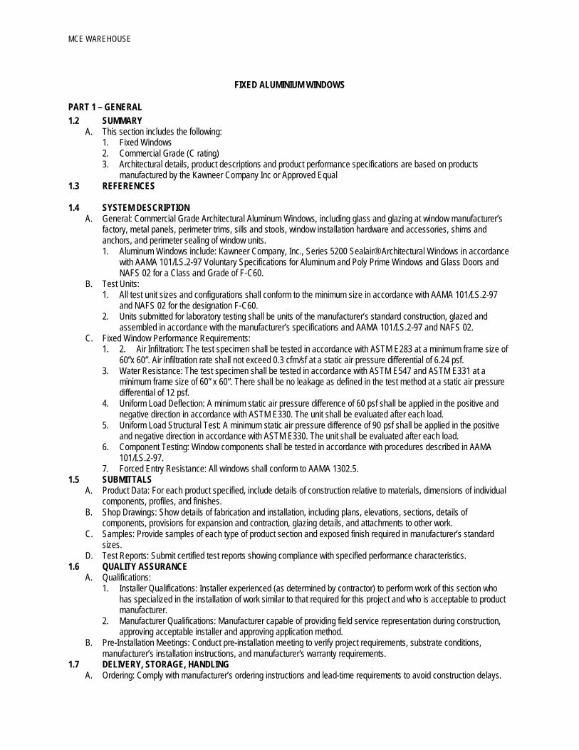
FIXED ALUMINIUM WINDOWS
PART 1 – GENERAL 1.2 SUMMARY
A. This section includes the following: 1. Fixed Windows 2. Commercial Grade (C rating) 3. Architectural details, product descriptions and product performance specifications are based on products
manufactured by the Kawneer Company Inc or Approved Equal 1.3 REFERENCES 1.4 SYSTEM DESCRIPTION
A. General: Commercial Grade Architectural Aluminum Windows, including glass and glazing at window manufacturer’s factory, metal panels, perimeter trims, sills and stools, window installation hardware and accessories, shims and anchors, and perimeter sealing of window units. 1. Aluminum Windows include: Kawneer Company, Inc., Series 5200 Sealair® Architectural Windows in accordance
with AAMA 101/I.S.2-97 Voluntary Specifications for Aluminum and Poly Prime Windows and Glass Doors and NAFS 02 for a Class and Grade of F-C60.
B. Test Units: 1. All test unit sizes and configurations shall conform to the minimum size in accordance with AAMA 101/I.S.2-97
and NAFS 02 for the designation F-C60. 2. Units submitted for laboratory testing shall be units of the manufacturer’s standard construction, glazed and
assembled in accordance with the manufacturer’s specifications and AAMA 101/I.S.2-97 and NAFS 02. C. Fixed Window Performance Requirements:
1. 2. Air Infiltration: The test specimen shall be tested in accordance with ASTM E283 at a minimum frame size of 60”x 60”. Air infiltration rate shall not exceed 0.3 cfm/sf at a static air pressure differential of 6.24 psf.
3. Water Resistance: The test specimen shall be tested in accordance with ASTM E547 and ASTM E331 at a minimum frame size of 60” x 60”. There shall be no leakage as defined in the test method at a static air pressure differential of 12 psf.
4. Uniform Load Deflection: A minimum static air pressure difference of 60 psf shall be applied in the positive and negative direction in accordance with ASTM E330. The unit shall be evaluated after each load.
5. Uniform Load Structural Test: A minimum static air pressure difference of 90 psf shall be applied in the positive and negative direction in accordance with ASTM E330. The unit shall be evaluated after each load.
6. Component Testing: Window components shall be tested in accordance with procedures described in AAMA 101/I.S.2-97.
7. Forced Entry Resistance: All windows shall conform to AAMA 1302.5. 1.5 SUBMITTALS
A. Product Data: For each product specified, include details of construction relative to materials, dimensions of individual components, profiles, and finishes.
B. Shop Drawings: Show details of fabrication and installation, including plans, elevations, sections, details of components, provisions for expansion and contraction, glazing details, and attachments to other work.
C. Samples: Provide samples of each type of product section and exposed finish required in manufacturer’s standard sizes.
D. Test Reports: Submit certified test reports showing compliance with specified performance characteristics. 1.6 QUALITY ASSURANCE
A. Qualifications: 1. Installer Qualifications: Installer experienced (as determined by contractor) to perform work of this section who
has specialized in the installation of work similar to that required for this project and who is acceptable to product manufacturer.
2. Manufacturer Qualifications: Manufacturer capable of providing field service representation during construction, approving acceptable installer and approving application method.
B. Pre-Installation Meetings: Conduct pre-installation meeting to verify project requirements, substrate conditions, manufacturer’s installation instructions, and manufacturer's warranty requirements.
1.7 DELIVERY, STORAGE, HANDLING A. Ordering: Comply with manufacturer’s ordering instructions and lead-time requirements to avoid construction delays.
MCE WAREHOUSE
B. Packing, Shipping, Handling, and Unloading: Deliver materials in manufacturer’s original, unopened, undamaged containers with identification labels intact.
C. Storage and Protection: Store materials protected from exposure to harmful weather conditions. Handle materials and components to avoid damage. Protect materials against damage from elements, construction activities, and other hazards before, during and after installation.
1.8 WARRANTY A. Project Warranty: Refer to “Conditions of the Contract” for project warranty provisions. B. Manufacturer’s Product Warranty: Submit, for owner’s acceptance, manufacturer’s standard warranty.
1. Warranty Period: Two (2) years from Date of Substantial Completion of the project provided however that the Limited Warranty shall begin in no event later than six months from date of shipment by Kawneer Company, Inc.
2. Glass: See Division 8 Section “Glazing” PART 2 – PRODUCTS 2.1 MANUFACTURERS
A. Acceptable Manufacturers: Subject to compliance with requirements, provide products by one of the following: 1. Bases of design: Kawneer Company, Inc., Series 5200 Sealair® Architectural Windows – 1 7/8” Deep Frame,
Fixed (F-C60) Or Approved Equal C. Substitutions:
1. General: Refer to Division 1 Section "Substitutions” for procedures and submission requirements. a. Architectural drawings indicate size, profiles, including dimensional requirements and are based on the
specific systems indicated. Other manufacturers' systems with equal performance characteristics may be considered.
b. Pre-Contract (Bidding Period) Substitutions: Submit written requests ten (10) days prior to bid date. c. Post-Contract (Construction Period) Substitutions: Submit written request in order to avoid installation and
construction delays. 2. Substitution Documentation:
a. Product Literature and Drawings: Submit product literature and drawings modified to suit specific project requirements and job conditions.
b. Certificates: Submit certificate(s) certifying substitute manufacturer (1) attesting to adherence to specification requirements for window system performance criteria, and (2) has been engaged in the design, manufacturer and fabrication of aluminum sliding doors for a period of not less than ten (10) years.
c. Test Reports: Submit test reports, certified by an independent laboratory, verifying compliance for each performance requirement as specified, as follows: air Infiltration, water infiltration, structural performance, thermal transmittance, condensation resistance, and sound transmission loss (STC).
d. Product Sample and Finish: Submit product sample, representative of the window system for the project, with specified finish and color.
3. Substitution Acceptance: Acceptance will be in written form, either as an addendum or modification, and documented by a formal change order signed by the Owner and Contractor.
2.2 MATERIALS A. Aluminum (Windows and Components): Alloy and temper recommended by manufacturer for type of use and finish
indicated, complying with the requirements of standards indicated below. 1. Extruded Material Standard: ASTM B 221, 6063-T6 alloy and temper.
B. Steel Reinforcement: Complying with ASTM A 36/ A 36M for structural shapes, plates and bars; ASTM A 611 for cold-rolled sheet and strip or ASTM A 570/ A 570M for hot-rolled sheet and strip.
C. Weather-stripping: Ventilators shall be double weather-stripped with a resilient foam core clad with UV-resistant elastomer.
D. Glazing Gaskets: Standard glazing gaskets shall be a dry glazed elastomer in accordance with ASTM C509-91. E. Glazing Sealant: Glazing material shall be a 100 percent silicone, neutral-cure sealant in accordance with AAMA
805.2-94, Group A. F. Fasteners: Where exposed, shall be 300 Series Stainless Steel.
2.3 HARDWARE NA 2.4 ACCESSORIES
A. Spacers, Setting Blocks, Gaskets, and Bond Breakers: Manufacturer's standard permanent, nonmigrating types in hardness recommended by manufacturer, compatible with sealants, and suitable for system performance requirements.
B. Framing system gaskets, sealants, and joint fillers as recommended by manufacturer for joint type.
MCE WAREHOUSE
C. Sealants and joint fillers for joints at perimeter of window system as specified in Division 7 Section "Joint Sealants." D. Perimeter Anchors: When steel anchors are used, provide insulation between steel material and aluminum material to
prevent galvanic action. F. Glazing: Factory glazing as specified in Division 8 Section “Glazing” G. Optional Exterior Panning and Interior Trims: Extruded aluminum, 6063-T6 alloy and temper, extruded to profiles and
details indicated. Seal exterior joints with manufacturer’s standard sealant to assure water-tight joints. H. Mullions and Cover Plates: Shall be extruded aluminum of 6063-T6 alloy and temper of profile and dimensions
indicated on drawings. Mullions shall provide structural properties to resist wind pressure required by performance criteria and standards.
2.5 RELATED MATERIALS A. B. Glass: Glass thickness and type shall be in accordance with glass manufacturer’s recommendations for
prescribed design pressure”. 1. Factory glazing (if required) shall be in accordance with manufacturer’s standard requirements. 2. Glazing materials shall be compatible with aluminum and those sealants and sealing materials used in composite
structure which have direct contact with the gasket. .
2.6 COMPONENTS A. The frame depth shall be not less than 1 7/8". B. All frame members shall have minimum wall thickness of 0.070" and shall provide the structural strength sufficient to
meet the specified performance requirements. C. Glazing beads shall be extruded aluminum and shall be a minimum thickness of 0.050". D. Reference to tolerances for wall thickness and other cross-sectional dimensions of window members are nominal and
in compliance with AA Aluminum Standards and Data. E. All references to dimensions for wall thicknesses and other cross-sectional dimensions of window members are
nominal and in compliance with ANSI H35.2-1990. 2.7 FABRICATION
A. General: Fabricate components per manufacturer’s installation instructions. When assembled, components will have accurately fitted joints to produce hairline joints. 1. Window Frame Joinery: Screw-Spline 2. Factory sealed frame and vent corner Joints
2.8 FINISHES A. All finishes shall be factory applied as recommended by the window manufacturer.
2.9 SOURCE QUALITY CONTROL A. Single Source Quality: Provide aluminum windows specified herein from a single source.
1. Building Enclosure System: When aluminum windows are part of a building enclosure system, including entrances, entrance hardware, curtain walls, storefront systems, sliding glass doors, slope glazing, and related products, provide building enclosure system products from a single source manufacturer.
PART 3 – EXECUTION 3.1 EXAMINATION
A. Site Verification of Conditions: Verify substrate conditions (which have been previously installed under other sections) are acceptable for product installation in accordance with manufacturer’s instructions. Verify openings are sized to receive window system and sill plate is level in accordance with manufacturer’s acceptable tolerances. Do not proceed with installation until unsatisfactory conditions have been corrected. 1. Field Measurements: Verify actual measurements/openings by field measurements before fabrication; show
recorded measurements on shop drawings. Coordinate field measurements, fabrication schedule with construction progress to avoid construction delays.
3.2 INSTALLATION A. General: Install window units plumb, level, and true to line, without warp or rack of frames or sash with manufacturer’s
prescribed tolerances. Provide support and anchor in place. 1. Dissimilar Materials: Provide separation of aluminum materials and other corrodible surfaces from sources of
corrosion or electrolytic action contact points by complying with AAMA 101, Appendix, titled “Dissimilar Materials.” 2. Weather Tight Construction: Install sill members and other members in a bed of sealant or with joint filler or
gaskets, to provide weather tight construction. Coordinate installation with wall flashings and other components of construction.
.
MCE WAREHOUSE
3.3 FIELD QUALITY CONTROL A. Field Tests: Architect shall select window units to be tested as soon as a representative portion of the project has been
installed, glazed, perimeter caulked and cured. Conduct tests for air infiltration and water penetration with manufacturer’s representative present. Tests not meeting specified performance requirements and units having deficiencies shall be corrected as part of the contract amount. 1. Testing: Testing shall be performed by a qualified independent testing agency. Refer to Division 1 Testing Section
for payment of testing and testing requirements. Testing Standard shall be per AAMA 502 including reference to ASTM E 783 for Air Infiltration Test and ASTM E 1105 for Water Penetration Test. a. Air Infiltration Tests: Conduct in accordance with ASTM E 783. Tests shall be conducted at a minimum
uniform static test pressure of 1.57 psf or a specified, but not to exceed 6.24 psf. The maximum allowable rates of air leakage for field testing shall not exceed 1.5 times the project specifications.
b. Water Penetration Tests: Water penetration tests shall be conducted at a static test pressure of 8 psf for Architectural (AW), 6.00 psf for Heavy Commercial (HC) and 3.00 psf for Commercial (C).
B. Manufacturer’s Field Services: Upon Owner’s request, provide manufacturer’s field service consisting of product use recommendations and periodic site visit for inspection of product installation in accordance with manufacturer’s instructions.
3.4 ADJUSTING A. Adjust operating window components to provide a tight fit at contact points and at weather-stripping for smooth
operation and a weather tight closure. 3.5 CLEANING
A. Remove temporary coverings and protection of adjacent work areas. Repair or replace damaged installed products. Clean installed products in accordance with manufacturer’s instructions prior to owner’s acceptance. Remove construction debris from project site and legally dispose of debris.
3.6 PROTECTION A. Protect installed product’s finish surfaces from damage during construction. Protect aluminum windows from damage
from grinding and polishing compounds, plaster, lime, acid, cement, or other harmful contaminants. Remove and replace damaged aluminum windows at no extra cost.
B. Protect adjacent work areas and finish surfaces from damage during product installation.
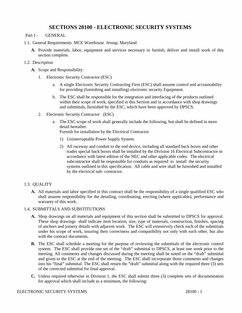
SECTIONS 28100 - ELECTRONIC SECURITY SYSTEMS Part 1 - GENERAL
1.1. General Requirements MCE Warehouse Jessup, Maryland
A. Provide materials, labor, equipment and services necessary to furnish, deliver and install work of this section complete.
1.2. Description
A. Scope and Responsibility:
1. Electronic Security Contractor (ESC)
a. A single Electronic Security Contracting Firm (ESC) shall assume control and accountability for providing (furnishing and installing) electronic security Equipment.
b. The ESC shall be responsible for the integration and interfacing of the products outlined within their scope of work, specified in this Section and in accordance with shop drawings and submittals, furnished by the ESC, which have been approved by DPSCS.
2. Electronic Security Contractor (ESC)
a. The ESC scope of work shall generally include the following, but shall be defined in more detail hereafter: Furnish for installation by the Electrical Contractor
1) Uninterruptable Power Supply System
2) All raceway and conduit to the end device, including all standard back boxes and other trades special back boxes shall be installed by the Division 16 Electrical Subcontractor in accordance with latest edition of the NEC and other applicable codes. The electrical subcontractor shall be responsible for conduits as required to install the security systems outlined in this specification. All cable and wire shall be furnished and installed by the electrical sub- contractor.
1.3. QUALITY
A. All materials and labor specified in this contract shall be the responsibility of a single qualified ESC who shall assume responsibility for the detailing, coordinating, erecting (where applicable), performance and warranty of this work.
1.4. SUBMITTALS AND SUBSTITUTIONS
A. Shop drawings on all materials and equipment of this section shall be submitted to DPSCS for approval. These shop drawings shall indicate item location, size, type of materials, construction, finishes, spacing of anchors and joinery details with adjacent work. The ESC will extensively check each of the submittals under his scope of work, insuring their correctness and compatibility not only with each other, but also with the contract documents.
B. The ESC shall schedule a meeting for the purpose of reviewing the submittals of the electronic control system. The ESC shall provide one set of the “draft” submittal to DPSCS, at least one week prior to the meeting. All comments and changes discussed during the meeting shall be noted on the “draft” submittal and given to the ESC at the end of the meeting. The ESC shall incorporate those comments and changes into his “final” submittal. The ESC shall return the “draft” submittal along with the required three (3) sets of the corrected submittal for final approval.
C. Unless required otherwise in Division 1, the ESC shall submit three (3) complete sets of documentation for approval which shall include as a minimum, the following:
ELECTRONIC SECURITY SYSTEMS 28100 - 1
1. Manufacturers’ product cut sheets for required equipment and major components to be provided. The product cut sheets shall be annotated to clearly identify only those specific functions and features that are applicable to the project. This task shall be performed by both the ESC and his sub-contractor, the Electrical Contractor, (EC).
2. System theory of operations that clearly define the operating parameters of the ESC systems being supplied, CCTV and Burglar Alarm.
3. A functional systems block diagram showing single-line interconnection of all of the major components of the CCTV and Burglar alarm and methods of integration supplied by the ESC.
4. Conduit riser diagrams that show all required conduit, raceway, wire, etc., for the interconnection of all components. As a minimum, diagrams shall include raceway/conduit size and type, wire fill, (type and size), equipment identification and location.
5. Schedules of all electronic operated devices and their functional attributes for all components being supplied. The schedules shall be formatted in alphanumeric order by architectural identification number. As a minimum for each commodity entry, the schedules shall include the following:
a. Associated architectural number (e.g.., Room number)
b. Assigned operation number (e.g..,Camera # )
c. Location of the control device (e.g. Master control, Warden’s office )
d. Functions associated with the controlled device .
e. Panel, enclosure or location of the function (e.g.., field, panel F1, panel F2, etc.)
Note: These schedules shall not be required during the submittal process. However, they shall be prepared and used for installation purposes and shall be incorporated into the as-built documentation
6. The submittal shall include descriptive responsibility for all parties where the ESC must interface with other trades/contractors.
a. Included with the three (3) sets of submittals the ESC must provide three (3) sets of “compact” diskettes that contain all submittal information as described above (excluding manufacturer’s cut sheets). The software programs utilized shall be of the following:
1) Drawings – AutoCAD
2) Word Processing – Word
3) Spreadsheet –Excel
4) Database – Access
Note: The files are supplied for document archival purposes and shall become the proprietary property of the recipient of the files.
b. The submittal shall reflect the systems as they are defined by the project plans and specifications, contract and signed/documented clarifications, substitutions and changes to the above documents by DPSCS.
D. Operating/Maintenance Manuals
1. ESC shall furnish three (3) copies of manuals and discs for CCTV system and their operation and the Burglar Alarm system and maintenance. These manuals shall include instructions for the care and operation of all of the components and their interface into a fully operational system that is in place at MCE warehouse..
ELECTRONIC SECURITY SYSTEMS 28100 - 2
2.Contents shall include minimally: wiring diagrams, as built-drawings with conduit routes, manufacturer’s warranties, troubleshooting directives, contact information with names, addresses, phone numbers, cable labeling. This list is NOT all inclusive, and may require additional information from the Project Manager as this document is reviewed.
1.5 DEFINITIONS TO THE ELECTRONICS SYSTEMS WORK A. The following definitions shall apply to all Security and Control Systems work. 1. PROVIDE shall mean that this contractor shall furnish, install, test, adjust, start-up program, interface and service all devices required for a complete and operational Security Control System.
1. INTEGRATION shall mean that this contractor shall provide all systems interfacing and programming necessary to physically and logically connect multiple systems through
hardware, software and project specific programming. 2. PROVIDE CABLING shall mean that this contractor shall provide cabling, raceways, concrete encased conduits, and rigid, EMT conduits or MC cabling as specified for each
type of location. 3. RESPONSIBILITY OF THIS CONTACTOR shall mean the work shall be performed by the
ESC contractor. 4. INTEGRATED SPECIAL SYSTEMS MANUFACTURER (ISM) shall mean organizations
That manufacture or produce systems, components, and materials that meet the requirements set forth in the contact documents. Only products available through a national distribution network shall be provided for this project.
5. ELECTRONIC SECURITY CONTRACTOR (ESC) and CONTRACTOR shall mean the firm that has responsibility for the work shown and specified in the contract documents.
6. SUBMIT shall mean all shop design, internal compliance to review, coordination and sending/delivery work for the contractor to obtain approval of all documentation necessary for implementation of the contract documents in compliance with applicable codes, standards and regulations based upon interpretation by the A/E of record.
7. INTEGRATED SECURITY AND CONTROL SYSTEMS (ISC) shall mean the Integrated Security and Control Systems shown and specified in the contract documents. The systems work includes the Central Processing Computer (CPS), Programmable Logic Control (PLC) and Video Surveillance (VSS) functions shown an specified. Systems not shown and not specified in the contract documents are specifically excluded from this project.
8. SUBSTANTIAL COMPLETION shall mean the date that the owner assumes ownership of the system as tested, and demonstrated to the owner by the ESC. A document with signatures of all parties will ensure that all parties to the contract agree to the date that the owner assumes responsibility for the system as demonstrated, tested with training having been concluded and contract documents having been turned over to the owner for final review.
1.6 PRODUCT HANDLING, STORAGE AND DELIVERY
A. Responsibility of the ESC.
1. Receive from carrier, unload and store all material that are furnished for installation by themselves and others.
2. Protect all materials during storage on the job and after installation. All protection required while working and/or cleaning adjacent materials shall be the responsibility of the ESC.
ELECTRONIC SECURITY SYSTEMS 28100 - 3
3. Provide an adequate secure, dry, lockable storage area or room for all ESC materials specified in this section.
4. Any scratches or disfigurement caused by on site handling are promptly cleaned and touched up with a compatible rust inhibitive primer. Shipping damage is the responsibility of the ESC.
5. Remove protective materials and clean all finished surfaces using clear water and non-abrasive detergent. Any protection required to clean adjacent materials shall be the responsibility of the ESC.
6. Work with the facility personnel as to where and how tools and inventory are to be maintained on site during the construction of this contract.
1.7 TRAINING—GENERAL INFORMATION
A. The ESC shall, without additional cost to the owner, provide representatives specially trained in the operation of the electronics systems with a thorough knowledge of their mechanisms. The representatives must be capable of training the Owner’s personnel in operation, repair and upkeep of the electronics package. .
Video taping by a videographer shall be required, and the resultant disc(s) shall be turned over to the institution for its use.
B. The ESC shall notify the Project Manager (PM) prior to substantial completion of the total security system that training is scheduled and ESC is to be notified of all training participants by name and position.
C. Training Staff
1.The ESC shall include in its training staff an individual or individuals knowledgeable of all the physical components and how the total integrated security system operates.
1.8 TEST, TRAINING AND VERIFICATION
A. The following establishes basic and minimum training requirements. The ESC shall provide technical services and materials to instruct operators and maintenance/programming personnel to operate, maintain and program the system.
1. Training shall be accomplished by fully qualified personnel who are thoroughly knowledgeable of the installation, equipment and software of the system. Instructions shall cover the material presented in the manuals through the use of classroom presentations and on-equipment training. Training shall include hardcopy class manuals supported by the review of professionally prepared audio-video presentations divided into volumes for operators and technical maintenance staff. Each volume shall be presented, separately, to the students specific to their work needs. 2. Information concerning class schedules, number of students per class, course outlines and a copy of
the instructor’s manual and handouts shall be provided by the ESC at least thirty (30) days in advance of the first class. Instructions shall be provided on-site and shall commence after the system is fully operational and shall be completed prior to system acceptance and turnover to the Owner.
3.Test and verification of each camera in the presence of the owner as to identification of each camera on the Vicon monitor and as to area of coverage of each camera. There will be no charge by the ESC if a camera requires re-positioning, re-labeling or lens adjustment to cover the owner’s intended area of coverage.
4.It is understood that during the two year ESC warranty period a 6 month, 12 month and 23 month scheduled visit to the institution the ESC shall review and act upon the list from MCE warehouse regarding any issues that require attention by the ESC. Each device shall be attended to by the ESC to ensure that each device is operating within the parameters set forth by the manufacturer. Issues that arise during the ESC’s review of each device shall be discussed on site by the ESC with the warehouse ELECTRONIC SECURITY SYSTEMS 28100 - 4
manager to rectify the issue to the satisfaction of all parties. 1.9 WARRANTY
A. The ESC firm warrants materials and workmanship furnished by their respective firm under this Section to be free from defects in material and workmanship for a period of two (2) years. The ESC shall transfer the remainder of the 3-year Vicon warranty and the Burglar alarm hardware warranty and associated project equipment warranties, from the manufacturers to the MCE warehouse, via a written document in favor of this facility.
Part 2 - PRODUCT
2.1 METAL RACKS
A. Acceptable Manufacturers
1. Except as otherwise specified herein, the equipment and materials of this Section shall be products of the following manufacturers:
a. Cabtron Systems, Inc., Northbrook, IL
b. Atlas-Soundolier, Parsippany, NY
c. Hoffman Engineering Co., Anoka, MN
d. Hammond Co., Anoka, MN
e. Amco
f. Emcor
B. General
The work required under this section of the specifications consists of the provision (furnishing and installation) of the equipment, consoles and housings necessary to rack mount the electronic equipment outlined in these specifications. The cabinets shall be sized to adequately house the equipment contained therein and sufficient space for the installation of a future NVR. The cabinet shall be installed in the location directed by the facility.
C. Construction
1. Racks shall be constructed using good workmanship practices and methods and in accordance with the standards established for the metal casework industry. They shall be constructed of materials in size, thickness and type that are suitable for the final installation environment and the normal operating condition
2. All racks are to be free of excessive gaps at corners and at the joining of structural members. They must also be free of protruding and/or sharp edges that may cause personal injury during normal operating condition.
3. Louvered openings/panels are to be supplied on all racks where heat dissipation is a consideration.
4. The rack in the MCE warehouse requires periodic maintenance. It shall be supplied with hinged and lockable doors with pulls allowing easy and controlled access to the equipment. Doors shall be manufactured consistent with the supplied racks. All enclosures from the same manufacturer shall be keyed alike. Screw applied access panels shall be acceptable only at locations where room conditions will not allow hinged doors to properly open. All door hardware shall be standard products for their intended use.
ELECTRONIC SECURITY SYSTEMS 28100 - 5
5. The rack shall be supplied with standard EIA mounting accessories to allow for the proper equipment mounting when appropriate. The rack shall be Pivotable on its base for serving both the front and rear at the same time. The rack shall be bolted to the floor.
2.2 Wiring Control in Racks
A. All control wiring within the rack shall be installed using good workmanship and standard shop wiring and control practices. Conductors shall be grouped and laced with nylon tie straps. Straps will be placed on each side of all bundle breakouts. Wiring will be supported at intervals not exceeding four inches and labeled at both ends. Each cable entering the rack shall be “service looped” from its cabinet entry to the top or bottom of the rack, depending upon its rack entry and must travel to the maximum height or bottom of the rack before landing at its intended termination point.
B. Wiring Standards
1. All control wiring systems shall use stranded copper conductors. All terminations shall be made on Sems type terminal strips or shall be made with crimp type lugs correctly sized for terminations to non- Sems type terminal strips and applied to conductor with crimping tool intended for use with the lug or connector used.
2. All wiring systems shall be labeled using Panduit or Brady Tags, machine printed and color coded with labeling and coding shown on shop drawings. Tags shall be attached no greater than 1 inch from their final termination point. White conductors shall be used only for neutral conductors, green only for grounding conductors with exceptions of low voltage control wiring that meet the requirements of Article 725 of the National Electric Code. All conductors within junction boxes, pull boxes and equipment enclosures shall be grouped and laced with nylon tie straps with identification tabs in individual sets, serving individual locks or groups. Conductor groups shall be identified on the tab with respect to device or area served. Control system conductors shall not be spliced. Control conductors shall be continuous between the control panel and the relay cabinet. CAT 6 cable shall be neatly, but not tightly strapped so as to damage the electronic integrity of the CAT 6 cable. In all cases, the manufacturer’s directions shall take precedence.
2.3 UNINTERRUPTABLE POWER SUPPLY SYSTEM
A. Acceptable Manufacturers
1. Except as otherwise specified herein, the equipment and materials of this Section shall be products of the following manufacturers and will be mounted in a rack in Master Control Center’s rack.
a. APC
B. General
The UPS system shall independently receive its power supply directly from the main/emergency power supply of the facility. The UPS system shall have the capacity to furnish the required total power for five (5) minutes. In the event of failure of the normal and emergency power sources, the UPS system shall have visual and audible trouble indicators that signal in the Master control center. The UPS shall be appropriately grounded per the latest National Electric Code.
C. Construction
1. The uninterruptable power supply shall have an output voltage of 120 volts and a full load current capable of supplying the system indicated herein. The unit shall operate with an input voltage of 120 volts, single phase, 60 cycle for units with outputs of 2.2kW or less. For units with outputs greater than 2.2 kW, input voltage shall be 208/240 volts, single phase 60 cycles. The output frequency
ELECTRONIC SECURITY SYSTEMS 28100 - 6
stability when operating without an input (inverter mode), shall be not less than +0.25%. Static voltage regulation shall not exceed +3% with a dynamic regulation of at least +10% for any load change not to exceed 20% of full load rating.
2. The unit shall operate normally with a +10% input voltage with an 0.85 power factor, from 0 degrees to 40 degrees C in a humidity of 0% to 95% and shall deliver 150% of rated power for 20 seconds and 125% for 10 minutes.
3. In the event of a loss of AC input power, the unit shall automatically switch to inverter power with no noticeable change of output power. Output power shall remain constant during transfer to/from input AC line power or DC source inverter power. In the event of an inverter malfunction, the unit will indicate and sound an inverter malfunction alarm and the inverter will shut down. The inverter shall shut down and drive an alarm when the input voltage drops below 95 volts DC.
4. Batteries: The batteries shall be sealed lead acid gel/cell maintenance free types. The batteries shall have heavy duty, radial grids for mechanical strength with low grid corrosion rate and PVC plastic separators for low internal resistance. Batteries shall be sized as recommended by the manufacturer to supply the necessary DC power to the UPS system for the extended run time as required. The batteries shall be protected with a circuit breaker and the charger shall give a fault indication and shut down if an over voltage condition exists. The charger shall receive source power from the same AC line circuits as the UPS AC inputs. Furnish the required number of batteries to supply 120 volts to the load for a period of time as required above in [2.3.C.1]. The complete system (batteries and UPS System) shall be furnished and guaranteed by the same manufacturer.
2.5 CLOSED CIRCUIT TELEVISION SYSTEM (CCTV) ALL CCTV EQUIPMENT SHALL BE VICON
A. All equipment shall be provided (furnished and installed) by the ESC. Conduits and wire work shall be provided (furnished and installed) by the sub-contractor electric contractor under the direction of the ESC.
B. Cameras
1. Cameras: IP Indoor 1.0 MP IP V921D-39MD-IP .Quantity 2
2. Cameras: IP Outdoor 2.0 MP IP V922D-39MD-IP Quantity 3
C. Monitors
1. 32” 1080p VM632LED in Facility manager office Quantity 1
D. NVR’s
1. Furnish NVR VPK-13TBXVR-R5 Pre-loaded software Quantity 1
E. Network Switch 1. NETSWITCH-24POE Quantity 1 F. Nucleus PC Server 1. VNUC-PCV7-RK with VNUC-SWV7 Pre-loaded software Quantity 1 G. PC Work Station 1. VWS-PCV7 with VWS-SW7 Pre-loaded software Quantity 1 H. Hard Drive replacement Kit for NVR 1. VN-SHD-2T SATA, 2TB Quantity 1
ELECTRONIC SECURITY SYSTEMS 28100 - 7
2.6 EXECUTION
1. The system shall be provided with a complete installation guide that details all steps necessary to install the newly provided system software changes into the computer system hardware that shall be in use. A user's reference manual shall also be provided. The user's reference manual shall detail all aspects of programming and operation of the system reflective of those changes required as a part of the new system.
2. The system shall have an interactive help facility built into the software, such that a user of the system shall be able to recall instructional text describing use of any permitted feature of the system while at a system terminal. The interactive help facility shall be entered by pressing the HELP key from any menu in the system.
3. The on-line documentation in the new system, shall be of sufficient depth for the new system such that the user need not refer to the written documentation supplied with the system, when he is at the system terminal.
5. Multi-User Capability:
a. The system shall be capable of accepting multiple LCD video terminal consoles. Each LCD terminal shall be capable of executing the full range of system commands concurrent with other terminal users.
b. Each LCD terminal connected to the system shall be capable of accepting a printer connected to the system through the terminal as provided by the new configuration. (i.e., the system shall not require an individual I/O port for each printer).
6. On-Line System Diagnostics: Cisco Systems for network components
a. The system shall provide the capability of running diagnostic software for the purpose of determining the source of a fault in the system hardware or tuning the performance of the system software.
b. The system shall provide on-line diagnostics that may be run without impairing function of the security system software. The on-line diagnostics to be provided shall cover DPU loading, virtual memory use, disk access and I/O operations. c. A set of off-line diagnostic programs shall also be provided for the purpose of isolating faulty computer system components. A diagnostic program for each device (to the board level) in the system shall be provided.
D. The system software shall maintain an error log which shall contain failure related information written when the software encounters errors in execution. The error log shall contain English language exclamations of the errors detected and any relevant error specific data.
2.7 BURGLAR ALARM SYSTEM
1.1 EXECUTION A. Examine and inspect all surfaces, anchors, and grounds that are to receive materials, fixtures, assemblies,
and equipment specified herein. Check location, "rough in", and field dimensions prior to beginning work. Report all unsatisfactory conditions in writing to the Project Manager.
ELECTRONIC SECURITY SYSTEMS 28100 - 8

B. Do not begin installation until all unsatisfactory conditions have been corrected.
1.2 INSTALLATION OF ALL SECURITY PRODUCTS: ESC/Electrical Contractor A. The ESC shall be responsible for the following:
1.Conductors and fiber to control system components and systems generating signals to be displayed at control consoles as well as all other electrical and electronic equipment furnished under this Section, shall be by the ESC. B. The electrical contractor sub-contractor shall be responsible for the following:
1. All electrical power and hookup of power to factory installed terminal blocks and power outlet including cut off switches and all other electrical equipment incidental to supply power. The facility shall provide power that is conditioned and transient protected for the Burglar alarm and, CCTV cameras, CCTV monitors and amplifiers, 2. All conduit complete with required Division 16 and Division 28 wire/cable, back boxes and installation of all special back boxes furnished and installed by the Division 16 Electrical Subcontractor shall be installed in accordance with and to the latest edition of the NEC and other applicable codes.
Additionally, the EC shall provide adequate small power at all necessary locations to accommodate the installation and testing of all security equipment and components. The ESC shall also take measures necessary to assure the EC the continuous availability of work spaces within the facility. The PM shall ensure that all equipment rooms and control rooms are complete and are environmentally controlled to maintain temperature and humidity to meet the manufacturer’s requirements of the electronics contained within, prior to starting the electronic control panel and equipment installation.
1.0 EXAMINATION
A. Examine site conditions to determine site conditions are acceptable without qualifications. Notify Owner in writing if deficiencies are found. Starting work is evidence that site conditions are acceptable.
1.1 INSTALLATION
A. Security Management System, including but not limited to alarm monitoring and CCTV system shall be installed in accordance with the manufacturer’s installation instructions.
B. Supervise installation to appraise ongoing progress of other trades and contracts, make allowances for all ongoing work, and coordinate the requirements of the installation of the Security Management System.
C. Cellular/Internet Communicator
1. Provide the ability to communicate signals wirelessly over either GSM/GPRS or CDMA cellular networks
1.2 FIELD TESTING AND CERTIFICATION
A. Testing: The alarm monitoring and CCTV system shall be tested in accordance with the following:
ELECTRONIC SECURITY SYSTEMS 28100 - 9

1. Conduct a complete inspection and test of all installed security monitoring equipment. This includes testing and verifying connection to equipment of other divisions.
2. Provide staff to test all devices and all operational features of the Security Management System for witness by the Owner’s representative and authorities having jurisdiction as applicable.
3. Correct deficiencies until satisfactory results are obtained.
4. Submit written copies of test results.
4.0 MONITORING AND RESPONSE….. Provide 24/7 monitoring by the contractor
1. If there is an intrusion event of any kind the Security Management system must:
a. Activate the external Siren
b. Contact the Police
c. Notify the owner via Cell phone and send an email
PART 2 Materials
1.List of Materials
A. BURGLAR ALARM: Amounts of devices and all other alarm required materials, equipment, conduit, wire and computer generated wire-applied labels and are the responsibility of the alarm company to complete a fully operational burglar alarm system as illustrated on the attached facility drawing.
Main CPU
Remote Key Pads
Exterior Siren with Strobe attached
Magnetic Door Contacts
Dual Detection motion detection devices
Central Station Transmitter IP and Cell Phone Transmission
B. BASIC CONTRUCTION INSTRUCTIONS:
1. All cable shall be pulled in conduit. 2. All cable shall be permanently labeled at both ends. 3. Home runs of cable from device to head end is required. 4. Crimps such as “beanies” and other crimp devices shall not be used on field wiring.
Solder and tape is required. 5. Plastic anchor attachment in drywall is permitted. 6. Lead anchor or Tapcon attachment on CMU/brick walls is required.
C. LICENCES AND PERMITS
All licenses shall be furnished and posted for pre-wiring, completion, and transmission. All other licenses for State of Maryland, associated county, and any other licenses and permits required to conclude the entire alarm and alarm related process that is under your contract shall be furnished to satisfy the authority having jurisdiction.
ELECTRONIC SECURITY SYSTEMS 28100 - 10
D. INSPECTION AND TESTING
Conduct a complete inspection and test of all installed access control and security monitoring equipment. This includes testing and verifying connection to equipment of other divisions such as life safety and elevators.
END OF SECTION 28100
ELECTRONIC SECURITY SYSTEMS 28100 - 11
TABLE OF CONTENTS
1.0
Introduction……………………………………………………………………………………………….1
2.0
Sampling Methods………………………………………………………………………………………..2
3.0
Survey Results
Bulk Sample Results ................................................................................................................. 4 XRF Lead Readings ................................................................................................................. 5
4.0
Conclusion……………………………………………………………………………………………….7
5.0
Photographic Documentation………………………………………………………………………….8
1
1.0 INTRODUCTION
Jenkins Environmental, Inc. was engaged by Maryland Correctional Enterprises to provide an asbestos and lead paint investigation of 8037 Brock Bridge Road in Jessup, Maryland. The site visit by Jenkins Environmental was conducted on July 2, 2014 by Larry D. Jenkins, a licensed AHERA Asbestos Inspector and Management Planner and certified Lead Paint Risk Assessor.
This assessment is only designed for identification of hazardous material conditions at the time of this investigation. JEI does not assume responsibility for the discovery and elimination of potential hazards that could cause accidents, injuries, or damage. This assessment includes conditions, operations, and practices as observed during the time of the site survey. Changes, procedural modifications or facility renovations made after the site assessment are not included.
2
2.0 SAMPLING METHODS
Asbestos
As part of the survey completed by Jenkins Environmental, bulk samples were collected of suspect materials for asbestos with each given a unique number, placed in single whirlpak bags, sealed and sent to an accredited laboratory for analysis using Polarized Light Microscopy with dispersion staining techniques.
The facility was visually inspected to identify the locations of suspected asbestos-containing building materials (ACBM). The suspected ACBM was touched by the accredited inspector in order to determine whether the material was friable. Friable by definition means any material that can be crumbled, pulverized or reduced to powder by hand pressure.
Homogeneous areas, those areas of material that are uniform in color and texture, were identified for both friable and non-friable ACBM. Each homogeneous area was classified as one of the following three types of material as defined by EPA.
a. Surfacing Material (SM): Material that is sprayed-on, trowelled on or otherwise applied to surfaces, such as acoustical plaster or other materials on surfaces for acoustical, fireproofing, or other purposes.
b. Thermal System Insulation (TSI): Material that is applied to pipes, fittings, boilers, breeching, tanks, ducts, or other interior structural components to prevent heat loss or gain, or water condensation, or for other purposes.
c. Miscellaneous Material (MISC): Interior building material that is on structural components, structural members or fixtures, such as floor and ceiling tiles and does not include surfacing material or thermal system insulation.
Lead Based Paint (LBP)
Lead paint was tested using an X-Ray Fluorescence Analyzer (LPA-1) manufactured by RMD, Inc. of Waltham, Massachusetts. The use of a portable, non-destructive testing device was selected due to its quick analysis and efficiency when compared to laboratory analysis. This report includes all readings, both positive and negative. Actual readings appearing on an LCD display are recorded on site while a data logger can generate a final report once downloaded to a computer.
XRF results are identified as positive or negative by the following rules:
“POSITIVE” refers to a sample that has a lead concentration of greater than 0.7 mg/cm² “NEGATIVE” refers to a sample that has lead concentration less than or equal to 0.7
mg/cm²

3
3.0 SURVEY RESULTS
Asbestos Survey Reports
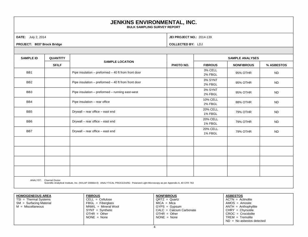
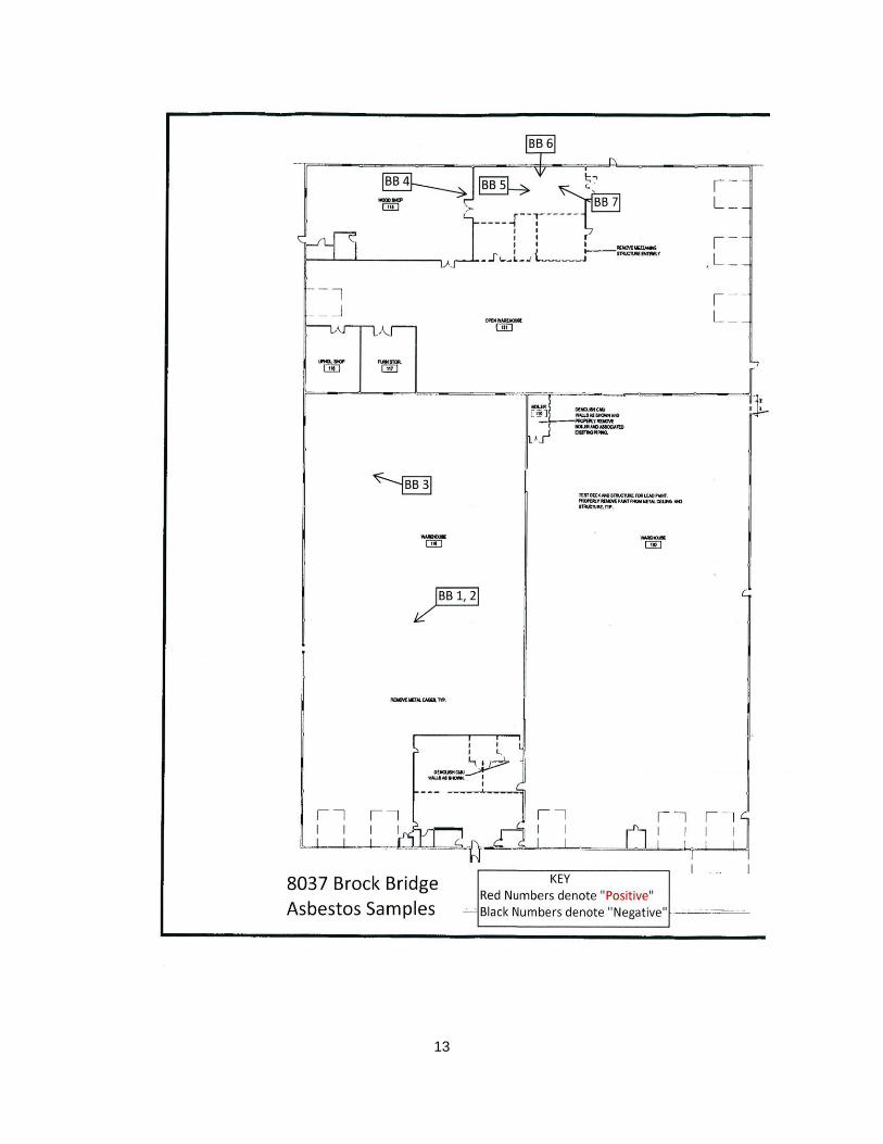
Seven (7) bulk samples of various materials were collected and analyzed for the presence of asbestos fibers.
Lead Based Paint
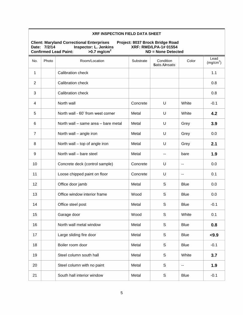
A total of twenty-six (26) XRF readings including 6 calibration checks were taken.
The following tables summarize the results of analysis:
HOMOGENEOUS AREA TSI = Thermal Systems SM = Surfacing Material M = Miscellaneous
FIBROUS CELL = Cellulose FBGL = Fiberglass MNWL = Mineral Wool SYNT = Synthetic OTHR = Other NONE = None
NONFIBROUS QRTZ = Quartz MICA = Mica GYPS = Gypsum CALC = Calcium Carbonate OTHR = Other NONE = None
ASBESTOS ACTN = Actinolite AMOS = Amosite ANTH = Anthophyllite CHRY = Chyrsotile CROC = Crocidolite TREM = Tremolite ND = No asbestos detected
4
JENKINS ENVIRONMENTAL, INC.
BULK SAMPLING SURVEY REPORT
DATE: July 2, 2014 PROJECT: 8037 Brock Bridge
JEI PROJECT NO.: 2014-139 COLLECTED BY: LDJ
SAMPLE ID
QUANTITY
SAMPLE LOCATION PHOTO NO.
SAMPLE ANALYSES
SF/LF
FIBROUS
NONFIBROUS
% ASBESTOS
BB1 Pipe insulation – preformed – 40 ft from front door 3% CELL
2% FBGL 95% OTHR ND
BB2 Pipe insulation – preformed – 40 ft from front door 3% SYNT
2% FBGL 95% OTHR ND
BB3 Pipe insulation – preformed – running east-west 3% SYNT
2% FBGL 95% OTHR ND
BB4 Pipe insulation – rear office 10% CELL
2% FBGL 88% OTHR ND
BB5 Drywall – rear office – east end 20% CELL
1% FBGL 79% OTHR ND
BB6 Drywall – rear office – east end 20% CELL
1% FBGL 79% OTHR ND
BB7 Drywall – rear office – east end 20% CELL
1% FBGL 79% OTHR ND
ANALYST: Charmel Dozier
Scientific Analytical Institute, Inc. (NVLAP 200664-0) ANALYTICAL PROCEDURE: Polarized Light Microscopy as per Appendix A, 40 CFR 763
5
XRF INSPECTION FIELD DATA SHEET
Client: Maryland Correctional Enterprises Project: 8037 Brock Bridge Road Date: 7/2/14 Inspector: L. Jenkins XRF: RMD/LPA-1# 01554 Confirmed Lead Paint: >0.7 mg/cm
2 ND = None Detected
No. Photo Room/Location Substrate Condition Satis./Unsatis
.
Color Lead
(mg/cm2)
1 Calibration check 1.1
2 Calibration check 0.8
3 Calibration check 0.8
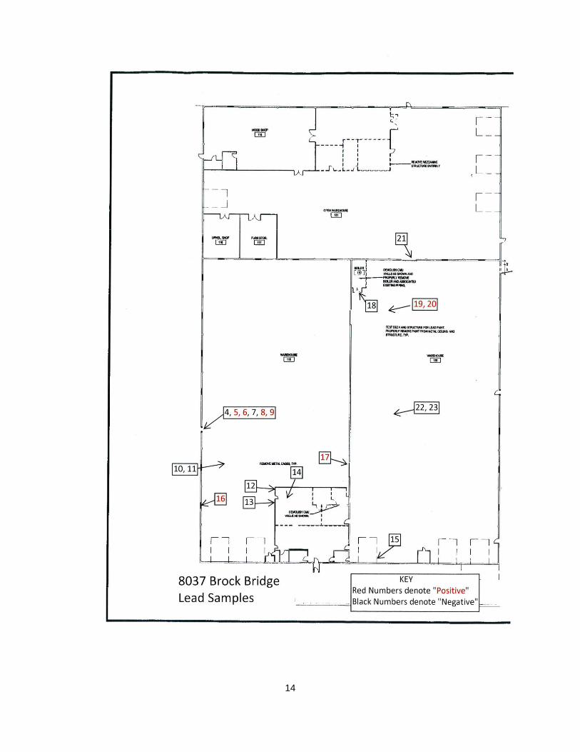
4 North wall Concrete U White -0.1
5 North wall - 60’ from west corner Metal U White 4.2
6 North wall – same area – bare metal Metal U Grey 3.9
7 North wall – angle iron Metal U Grey 0.0
8 North wall – top of angle iron Metal U Grey 2.1
9 North wall – bare steel Metal -- bare 1.9
10 Concrete deck (control sample) Concrete U -- 0.0
11 Loose chipped paint on floor Concrete U -- 0.1
12 Office door jamb Metal S Blue 0.0
13 Office window interior frame Wood S Blue 0.0
14 Office steel post Metal S Blue -0.1
15 Garage door Wood S White 0.1
16 North wall metal window Metal S Blue 0.8
17 Large sliding fire door Metal S Blue <9.9
18 Boiler room door Metal S Blue -0.1
19 Steel column south hall Metal S White 3.7
20 Steel column with no paint Metal S -- 1.9
21 South hall interior window Metal S Blue -0.1
6
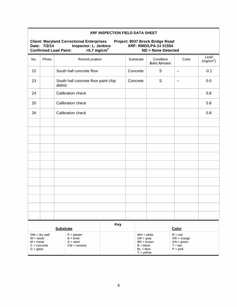
XRF INSPECTION FIELD DATA SHEET
Client: Maryland Correctional Enterprises Project: 8037 Brock Bridge Road Date: 7/2/14 Inspector: L. Jenkins XRF: RMD/LPA-1# 01554 Confirmed Lead Paint: >0.7 mg/cm
2 ND = None Detected
No. Photo Room/Location Substrate Condition Satis./Unsatis
.
Color Lead
(mg/cm2)
22 South hall concrete floor Concrete S -- -0.1
23 South hall concrete floor paint chip debris
Concrete S -- 0.0
24 Calibration check 0.8
25 Calibration check 0.8
26 Calibration check 0.8
Substrate
Key
Color
DW = dry wall W = wood M = metal C = concrete G = glass
P = plaster B = brick S = steel CM = ceramic
WH = white GR = gray BR = brown B = black BL = blue Y = yellow
R = red OR = orange GN = green T = tan P = pink
7
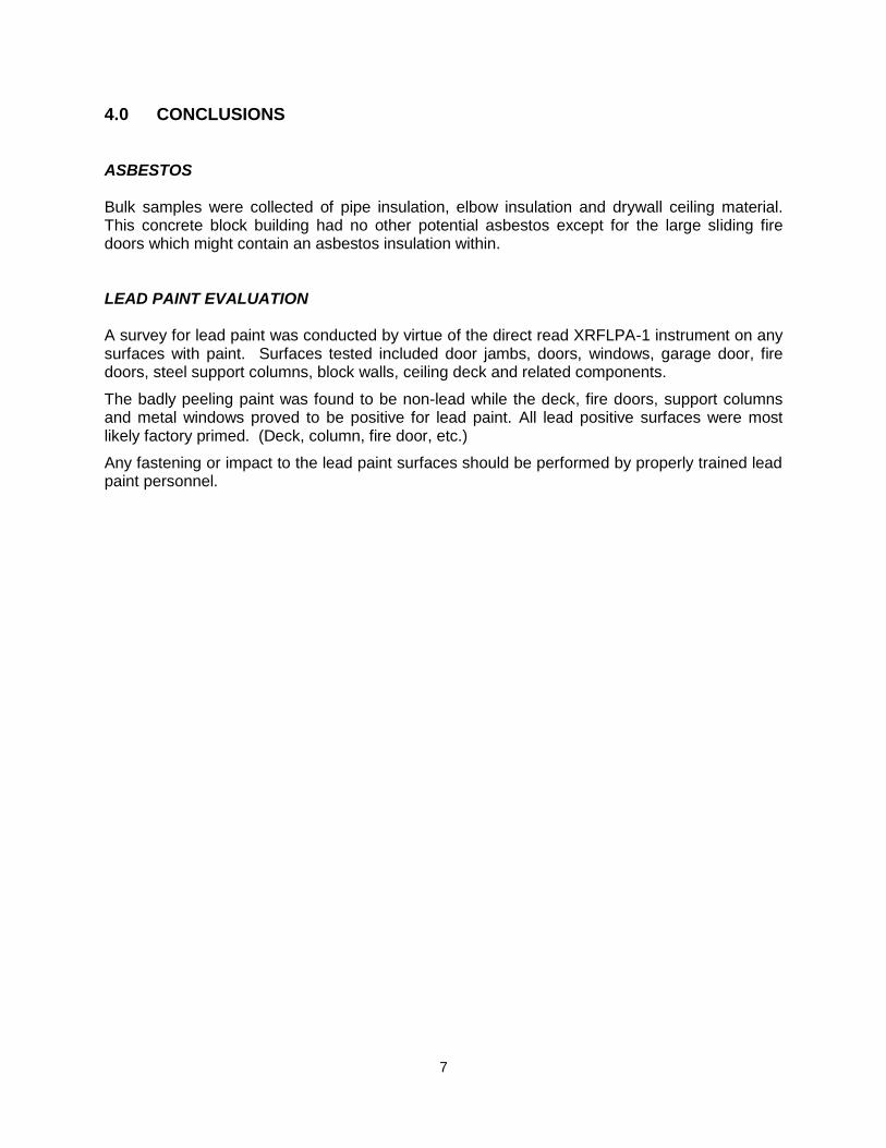
4.0 CONCLUSIONS ASBESTOS Bulk samples were collected of pipe insulation, elbow insulation and drywall ceiling material. This concrete block building had no other potential asbestos except for the large sliding fire doors which might contain an asbestos insulation within. LEAD PAINT EVALUATION A survey for lead paint was conducted by virtue of the direct read XRFLPA-1 instrument on any surfaces with paint. Surfaces tested included door jambs, doors, windows, garage door, fire doors, steel support columns, block walls, ceiling deck and related components.
The badly peeling paint was found to be non-lead while the deck, fire doors, support columns and metal windows proved to be positive for lead paint. All lead positive surfaces were most likely factory primed. (Deck, column, fire door, etc.)
Any fastening or impact to the lead paint surfaces should be performed by properly trained lead paint personnel.
8
5.0 PHOTOGRAPHIC DOCUMENTATION
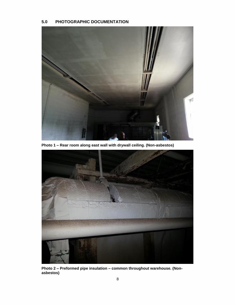
Photo 1 – Rear room along east wall with drywall ceiling. (Non-asbestos)
Photo 2 – Preformed pipe insulation – common throughout warehouse. (Non-asbestos)
9
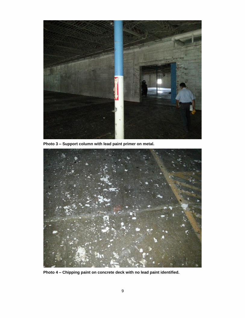
Photo 3 – Support column with lead paint primer on metal.
Photo 4 – Chipping paint on concrete deck with no lead paint identified.
10
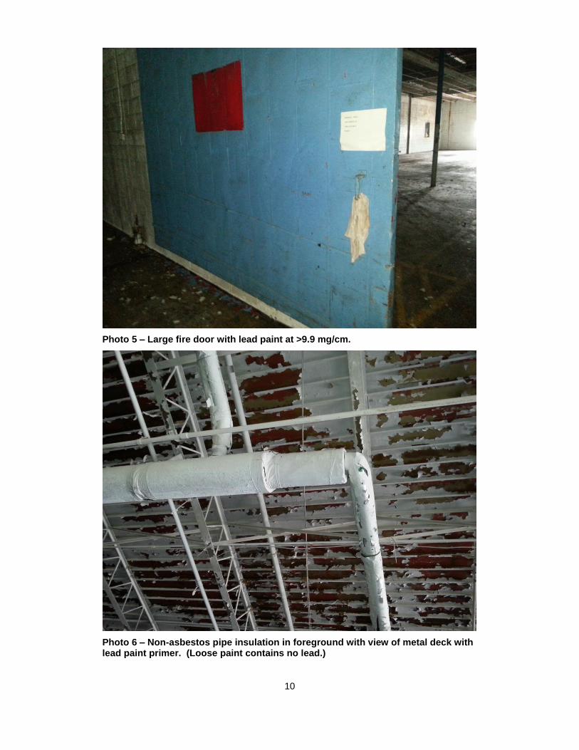
Photo 5 – Large fire door with lead paint at >9.9 mg/cm.
Photo 6 – Non-asbestos pipe insulation in foreground with view of metal deck with lead paint primer. (Loose paint contains no lead.)
11
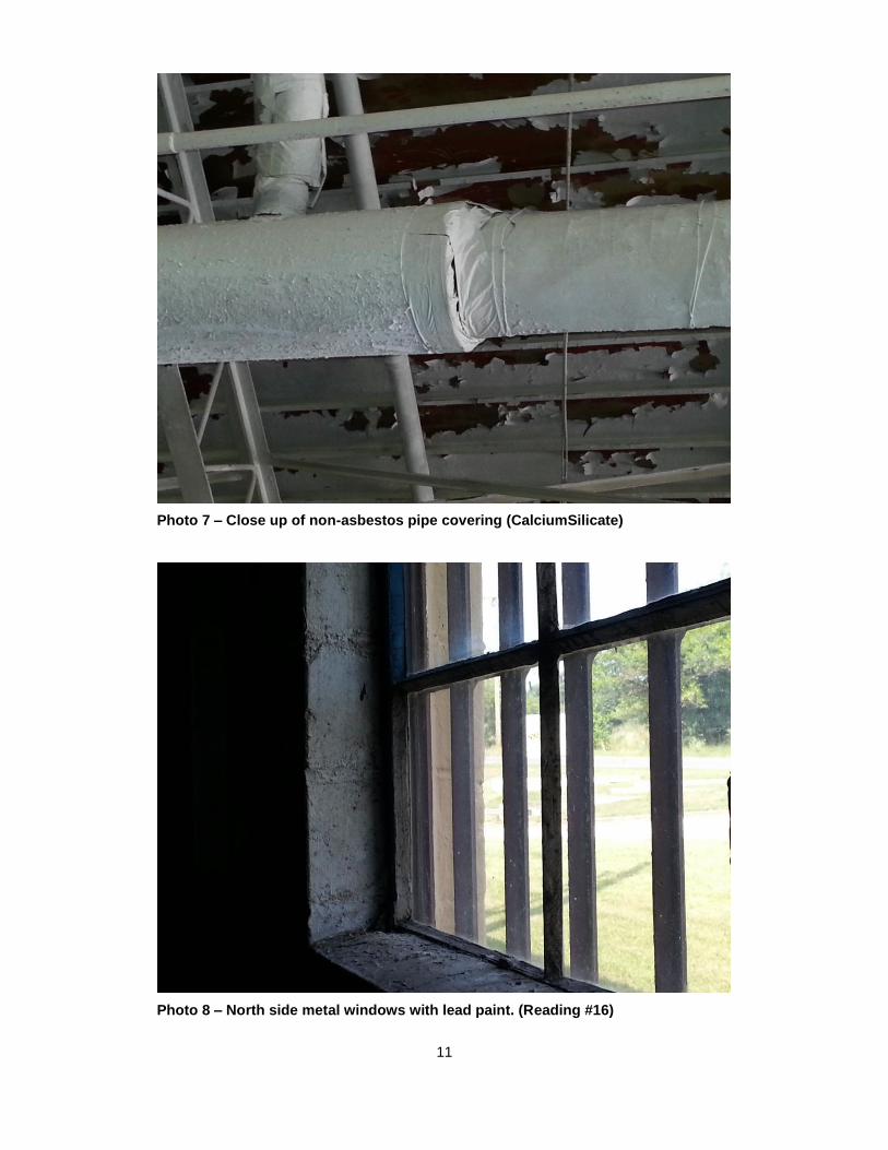
Photo 7 – Close up of non-asbestos pipe covering (CalciumSilicate)
Photo 8 – North side metal windows with lead paint. (Reading #16)
12
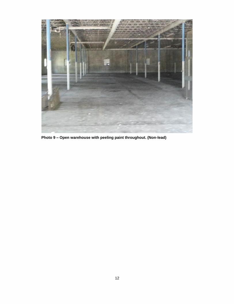
Photo 9 – Open warehouse with peeling paint throughout. (Non-lead)
13
14