Embed Size (px)
Citation preview

Hilti, Inc. 5400 South 122nd East Avenue
Tulsa, OK 74146
1-800-879-8000 www.hilti.com
Attached are page(s) from the 2011 Hilti North American Product Technical Guide. For complete details on this product, including data development, product specifications, general suitability, installation, corrosion, and spacing & edge distance guidelines, please refer to the Technical Guide, or contact Hilti.

/
μ
/ / /
/
/ /
/ /
C

/
/
//
/
/

/ /


h ≥ hmin
sdesign cdesign
h
c
s
cc
s
s c
Mechanical Anchoring Systems
3.3.6 KWIK Bolt 3 Expansion Anchor
298 Hilti, Inc. (US) 1-800-879-8000 | www.us.hilti.com I en español 1-800-879-5000 I Hilti (Canada) Corp. 1-800-363-4458 I www.hilti.ca I Anchor Fastening Technical Guide 2011
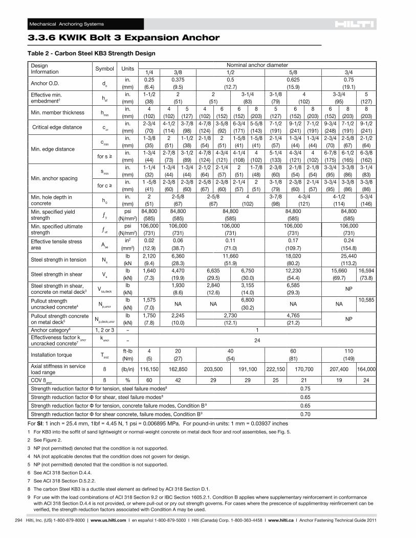
1 SeeKWIKBolt3ProductLineTableinSection3.3.6.6forafulllistandanchorlengthandthreadlengthconfigurations.2 LoadsforKWIKBolt3areapplicableforbothcarbidedrillbitsandmatchedtoleranceHiltiDD-BorDD-Cdiamond
core bits in sizes ranging from 1/2 inch to 1 inch.3 ThedeepembedmentdepthforstainlesssteelKWIKBolt3anchorsis8inch(203mm).4 Boltfractureloadsaredeterminedbytestinginajigaspartofproductqualitycontrol.Thesevaluesarenotintended
for design purposes.5 Boltstrengthspecifiedbyminimumtensileandyieldstrength.Boltfractureloadnotapplicable.6 BoltfractureloadnotapplicabletocarbonsteelCountersunkKWIKBolt3.Thetensileandyieldstrengthsare f ut≥105ksiandf y≥90ksi.7 BoltfractureloadnotapplicabletostainlesssteelCountersunkKWIKBolt3.Thetensileandyieldstrengthsare fut≥90ksiandf y≥76ksi.8 For 3/4 x 12, fut≥88ksiandf y≥75ksi.Boltfractureloadnotapplicable.
3.3.6.4 Allowable Stress DesignTable 5 - KWIK Bolt 3 Specifications and Properties1
BoltSize Details
in. 1/4 3/8 1/2(mm) (6.4) (9.5) (12.7)
d bit nominal bit diameter2 in. 1/4 3/8 1/2
hmin/hnom/hdeep depth of embedmentin. 1-1/8 2 3 1-5/8 2-1/2 3-1/2 2-1/4 3-1/2 4-3/4
(mm) (29) (51) (76) (41) (64) (89) (57) (89) (121)
hominimum/standard/deep hole depth
in. 1-3/8 2-1/4 3-1/4 2 2-7/8 3-7/8 2-3/4 4 5-1/4(mm) (35) (57) (83) (51) (73) (89) (70) (102) (133)
dh fixture holein. 5/16 7/16 9/16
(mm) (8) (11) (14)
Tinst Installation Torque
Normal weight & Light weight Concrete
Carbon Steel ft-lb 4 20 40HDG (Nm) (5) (27) (54)
Stainless Steelft-lb 4 20 40
(Nm) (5) (27) (54)
Grout Filled Block Carbon Steel
ft-lb 4 15 25
(Nm) (5) (20) (34)h min. base material thickness in. 3 inch (76 mm) or 1.3 times embedment, whichever number is greater
BoltFracture Load
Carbon Steel 2900 lb4,6 7200 lb4,6 12400 lb4
HDG no offering no offering 12400 lb4
Stainless Steel 2900 lb4,7 7200 lb4,7 12400 lb4
BoltSize Details
in. 5/8 3/4 1(mm) (15.9) (19.1) (25.4)
d bit nominal bit diameter2 in. 5/8 3/4 1
hmin/hnom/hdeep depth of embedmentin. 2-3/4 4 5-1/2 3-1/4 4-3/4 6-1/23
4-1/2 6 9(mm) (70) (102) (140) (83) (121) (165) (114) (152) (229)
hominimum/standard/deep hole depth
in. 3-3/8 4-5/8 6-1/8 4 5-1/2 7 5-1/2 7 10(mm) (86) (117) (156) (102) (140) (178) (140) (178) (254)
dh fixture holein. 11/16 13/16 1-1/8
(mm) (17) (21) (29)
Tinst Installation Torque
Normal weight & Light weight Concrete
Carbon Steel ft-lb 60 110 150HDG (Nm) (81) (149) (203)
Stainless Steelft-lb 60 110 150
(Nm) (81) (149) (203)
Grout Filled Block Carbon Steel
ft-lb 65 120–
(Nm) (88) (163)
h min. base material thickness in. 3 inch (76 mm) or 1.3 times embedment, whichever number is greater
BoltFracture Load
Carbon Steel 19600 lb4 28700 lb4,8 ƒut≥88ksi,ƒy≥75ksi 5
HDG 19600 lb4 28700 lb4 no offeringStainless Steel 21900 lb4 ƒut≥76ksi,ƒy≥64ksi 5 ƒut≥76ksi,ƒy≥64ksi 5


Mechanical Anchoring Systems
3.3.6 KWIK Bolt 3 Expansion Anchor
306 Hilti, Inc. (US) 1-800-879-8000 | www.us.hilti.com I en español 1-800-879-5000 I Hilti (Canada) Corp. 1-800-363-4458 I www.hilti.ca I Anchor Fastening Technical Guide 2011
V2
V1
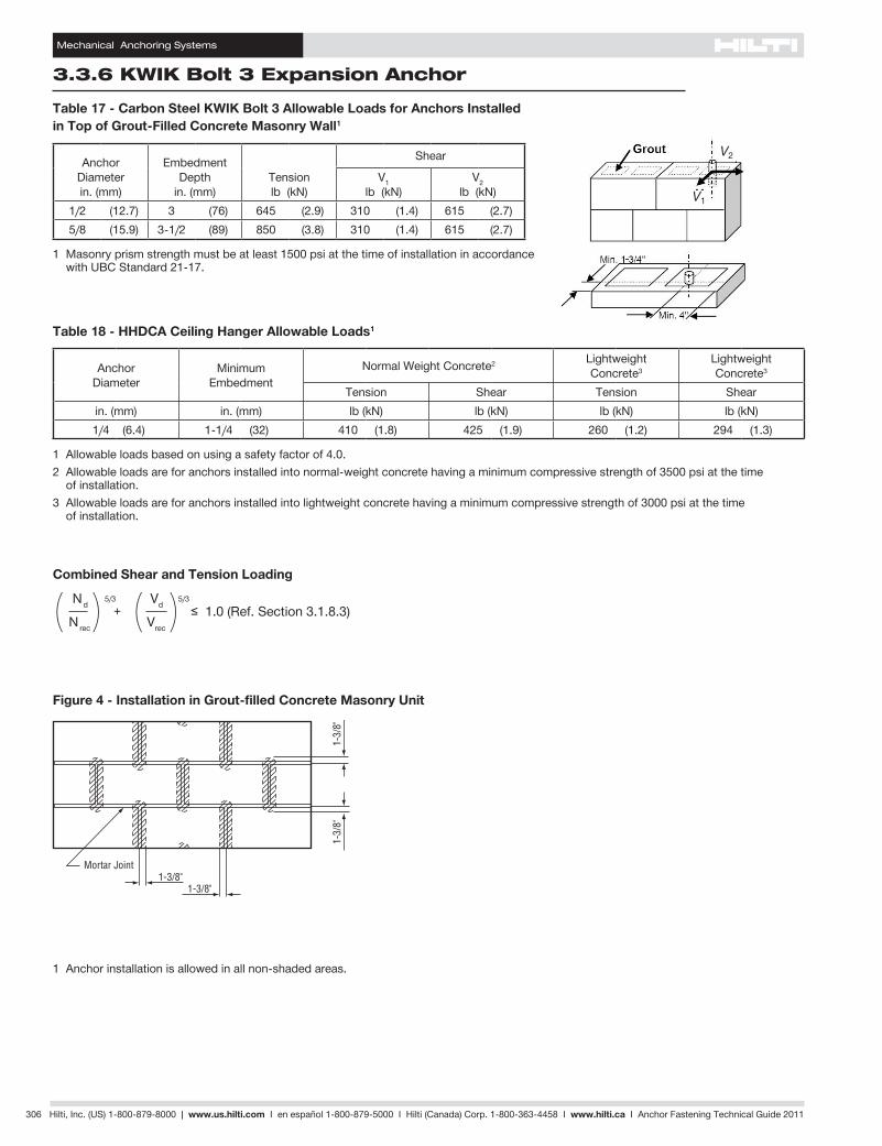
Table 17 - Carbon Steel KWIK Bolt 3 Allowable Loads for Anchors Installed in Top of Grout-Filled Concrete Masonry Wall1
Anchor Diameterin. (mm)
Embedment Depth
in. (mm)Tension lb (kN)
Shear
V1 lb (kN)
V2 lb (kN)
1/2 (12.7) 3 (76) 645 (2.9) 310 (1.4) 615 (2.7)5/8 (15.9) 3-1/2 (89) 850 (3.8) 310 (1.4) 615 (2.7)
1 Masonry prism strength must be at least 1500 psi at the time of installation in accordance with UBC Standard 21-17.
Table 18 - HHDCA Ceiling Hanger Allowable Loads1
Anchor Diameter
Minimum Embedment
Normal Weight Concrete2 Lightweight Concrete3
Lightweight Concrete3
Tension Shear Tension Shearin. (mm) in. (mm) lb (kN) lb (kN) lb (kN) lb (kN)1/4 (6.4) 1-1/4 (32) 410 (1.8) 425 (1.9) 260 (1.2) 294 (1.3)
1 Allowable loads based on using a safety factor of 4.0.2 Allowable loads are for anchors installed into normal-weight concrete having a minimum compressive strength of 3500 psi at the time
of installation.3 Allowable loads are for anchors installed into lightweight concrete having a minimum compressive strength of 3000 psi at the time
of installation.
1 Anchor installation is allowed in all non-shaded areas.
Figure 4 - Installation in Grout-filled Concrete Masonry Unit
( )+ ≤ 1.0 (Ref. Section 3.1.8.3)( )Nrec Vrec
Combined Shear and Tension Loading
Nd 5/3 Vd 5/3

/
c
c
sth
V
N
/

f
c/h
f
c/h
f
s/h
f
s/h

Mechanical Anchoring Systems
KWIK Bolt 3 Expansion Anchor 3.3.6
Hilti, Inc. (US) 1-800-879-8000 | www.us.hilti.com I en español 1-800-879-5000 I Hilti (Canada) Corp. 1-800-363-4458 I www.hilti.ca I Anchor Fastening Technical Guide 2011 309
Spacing — Tension hmin≤ h act≤h nom hact ≥ h nom ƒAN = s/hact + 0.88 ƒAN = s/hnom + 0.88 3.13 3.13
Edge Distance — Tension hmin≤ h act≤h nom hact ≥ h nom ƒRN = c/h act + 2 ƒRN = c/h nom + 2 3.75 3.75
Spacing — Shear hmin≤ h act≤h nom hact ≥ h nom ƒAV =
s/hact + 10.25 ƒAV = s/hnom + 10.25
12.5 12.5
Edge Distance — Shear h act ≥ hmin
perpendicular toward edge
ƒRV1 = c
3hmin
parallel to edge
ƒRV2 = c/h min + 0.75
3.75perpendicular away from edge
ƒRV3 = c/h min + 5.82
8.82
Influence of Edge Distance and Anchor Spacing on Anchor Performance
Note: Edge distance and anchor spacing for all lightweight and sand-lightweight concrete are obtained by dividing the normal-weight dimensions by 0.75 and 0.85, respectively.
Note: Tables apply for listed embedment depths. Reduction factors for other embedment depths must be calculated using equations below.
Standard Anchor Embedments (in.)
hmin 1-1/8
1/4 hnom 2
hdeep 3
hmin 1-5/8
3/8 hnom 2-1/2
hdeep 3-1/2
hmin 2-1/4
1/2 hnom 3-1/2
hdeep 4-3/4
Load Adjustment Factors for 1/4" Diameter Anchors
AdjustmentFactor1/4 in.
SpacingTension
ƒAN
Edge DistanceTension
ƒRN
Spacing Shear
ƒAV
Edge Distance Shear
⊥ Toward EdgeƒRV1
II Toward EdgeƒRV1
⊥ Away from EdgeƒRV3
EmbedmentDepth, in. 1-1/8 ≥ 2 1-1/8 ≥ 2 1-1/8 ≥ 2 ≥ 1-1/8 ≥ 1-1/8 ≥ 1-1/8
Spac
ing/
Edge
Dis
tanc
e, in
.
1-1/8 0.60 0.80 0.901-11/16 0.75 0.93 0.94 0.50 0.60 0.831-3/4 0.78 0.95 0.94 0.52 0.61 0.842 0.85 0.60 1.00 0.80 0.96 0.90 0.59 0.67 0.862 -1/4 0.92 0.64 0.83 0.98 0.91 0.67 0.73 0.892-1/2 0.99 0.68 0.87 1.00 0.92 0.74 0.79 0.913 1.00 0.76 0.93 0.94 0.89 0.91 0.963-3/8 0.82 0.98 0.96 1.00 1.00 1.003-1/2 0.84 1.00 0.96 1.00 1.00 1.004 0.92 0.984-1/2 1.00 1.004-3/45
Load Adjustment Factors for 3/8" Diameter Anchors
AdjustmentFactor3/8 in.
SpacingTension
ƒAN
Edge DistanceTension
ƒRN
Spacing Shear
ƒAV
Edge Distance Shear
⊥ Toward EdgeƒRV1
II Toward EdgeƒRV1
⊥ Away from EdgeƒRV3
EmbedmentDepth, in. 1-5/8 ≥ 2-1/2 1-5/8 ≥ 2-1/2 1-5/8 ≥ 2-1/2 ≥ 1-5/8 ≥ 1-5/8 ≥ 1-5/8
Spac
ing/
Edge
Dis
tanc
e, in
.
1-5/8 0.60 0.80 0.902 0.67 0.86 0.922-1/4 0.72 0.90 0.932-1/2 0.77 0.60 0.94 0.80 0.94 0.90 0.51 0.61 0.833 0.87 0.66 1.00 0.85 0.97 0.92 0.62 0.69 0.873-1/4 0.92 0.70 0.88 0.98 0.92 0.67 0.73 0.893-1/2 0.97 0.73 0.91 0.99 0.93 0.72 0.77 0.903-3/4 1.00 0.76 0.93 1.00 0.94 0.77 0.82 0.924 0.79 0.96 0.95 0.82 0.86 0.944-1/2 0.86 1.00 0.96 0.92 0.94 0.975 0.92 0.98 1.00 1.00 1.005-5/8 1.00 1.005-3/4
Load Adjustment Factors for 1/2" Diameter Anchors
AdjustmentFactor1/2 in.
SpacingTension
ƒAN
Edge DistanceTension
ƒRN
Spacing Shear
ƒAV
Edge Distance Shear
⊥ Toward EdgeƒRV1
II Toward EdgeƒRV1
⊥ Away from EdgeƒRV3
EmbedmentDepth, in. 2-1/4 ≥ 3-1/2 2-1/4 ≥ 3-1/2 2-1/4 ≥ 3-1/2 ≥ 2-1/4 ≥ 2-1/4 ≥ 2-1/4
Spac
ing/
Edge
Dis
tanc
e, in
.
2-1/4 0.60 0.80 0.902-1/2 0.64 0.83 0.913 0.71 0.89 0.933-3/8 0.76 0.93 0.94 0.50 0.60 0.833-3/4 0.81 0.62 0.98 0.82 0.95 0.91 0.56 0.64 0.854-1/4 0.88 0.67 1.00 0.86 0.97 0.92 0.63 0.70 0.874-3/4 0.96 0.71 0.90 0.99 0.93 0.70 0.76 0.905 1.00 0.74 0.91 1.00 0.93 0.74 0.79 0.915-3/4 0.81 0.97 0.95 0.85 0.88 0.956 0.83 1.00 0.96 0.89 0.91 0.966-1/2 0.87 0.97 0.96 0.97 0.997-1/4 0.94 0.99 1.00 1.00 1.007-3/4 1.00 1.00

Mechanical Anchoring Systems
3.3.6 KWIK Bolt 3 Expansion Anchor
310 Hilti, Inc. (US) 1-800-879-8000 | www.us.hilti.com I en español 1-800-879-5000 I Hilti (Canada) Corp. 1-800-363-4458 I www.hilti.ca I Anchor Fastening Technical Guide 2011
Influence of Edge Distance and Anchor Spacing on Anchor Performance
Note: Edge distance and anchor spacing for all lightweight and sand-lightweight concrete are obtained by dividing the normal-weight dimensions by 0.75 and 0.85, respectively.
1. Embedment depth shown reflects embedment for carbon steel anchor, deep embedment depth for stainless steel anchor is 8 inch.
Standard Anchor Embedments (in.)
hmin 2-3/4
5/8 hnom 4
hdeep 5-1/2
hmin 3-1/4
3/4 hnom 4-3/4
hdeep 6-1/21
hmin 4-1/2
1 hnom 6
hdeep 9
Note: Tables apply for listed embedment depths. Reduction factors for other embedment depths must be calculated using equations below.
Spacing — Tension
hmin≤ h act≤h nom hact ≥ h nom ƒAN = s/hact + 0.88 ƒAN = s/hnom + 0.88 3.13 3.13
Edge Distance — Tension
hmin≤ h act≤h nom hact ≥ h nom ƒRN = c/h act + 2 ƒRN = c/h nom + 2 3.75 3.75
Spacing — Shear
hmin≤ h act≤h nom hact ≥ h nom ƒAV =
s/hact + 10.25 ƒAV = s/hnom + 10.25
12.5 12.5
Edge Distance — Shear h act ≥ hmin
perpendicular toward edge
ƒRV1 = c
3hmin
parallel to edge
ƒRV2 = c/h min + 0.75
3.75perpendicular away from edge
ƒRV3 = c/h min + 5.82
8.82
Load Adjustment Factors for 5/8" Diameter Anchors
AdjustmentFactor5/8 in.
SpacingTension
ƒAN
Edge DistanceTension
ƒRN
Spacing Shear
ƒAV
Edge Distance Shear
⊥ Toward EdgeƒRV1
II Toward EdgeƒRV1
⊥ Away from EdgeƒRV3
EmbedmentDepth, in. 2-3/4 ≥ 4 2-3/4 ≥ 4 2-3/4 ≥ 4 ≥ 2-3/4 ≥ 2-3/4 ≥ 2-3/4
Spac
ing/
Edge
Dis
tanc
e, in
.
2-3/4 0.60 0.80 0.903-1/2 0.69 0.87 0.924 0.75 0.60 0.92 0.80 0.94 0.904-1/4 0.77 0.62 0.95 0.82 0.94 0.91 0.52 0.61 0.844-3/4 0.83 0.66 1.00 0.85 0.96 0.92 0.58 0.66 0.865-1/2 0.92 0.72 0.90 0.98 0.93 0.67 0.73 0.896 0.98 0.76 0.93 0.99 0.94 0.73 0.78 0.916-1/4 1.00 0.78 0.95 1.00 0.95 0.76 0.81 0.927 0.84 1.00 0.96 0.85 0.88 0.957-1/2 0.88 0.97 0.91 0.93 0.977-3/4 0.90 0.98 0.94 0.95 0.988-1/2 0.96 0.99 1.00 1.00 1.009 1.00
Load Adjustment Factors for 3/4" Diameter Anchors
AdjustmentFactor3/4 in.
SpacingTension
ƒAN
Edge DistanceTension
ƒRN
Spacing Shear
ƒAV
Edge Distance Shear
⊥ Toward EdgeƒRV1
II Toward EdgeƒRV1
⊥ Away from EdgeƒRV3
EmbedmentDepth, in. 3-1/4 ≥ 4-3/4 3-1/4 ≥ 4-3/4 3-1/4 ≥ 4-3/4 ≥ 3-1/4 ≥ 3-1/4 ≥ 3-1/4
Spac
ing/
Edge
Dis
tanc
e, in
.
3-3/8 0.61 0.81 0.904 0.67 0.86 0.925 0.77 0.62 0.94 0.81 0.94 0.90 0.51 0.61 0.835-3/4 0.85 0.67 1.00 0.86 0.96 0.92 0.59 0.67 0.866-1/4 0.90 0.70 0.88 0.97 0.93 0.64 0.71 0.886-1/2 0.92 0.72 0.90 0.98 0.93 0.67 0.73 0.897 0.97 0.75 0.93 0.99 0.94 0.72 0.77 0.907-1/2 1.00 0.79 0.95 1.00 0.95 0.77 0.82 0.928-1/4 0.84 1.00 0.96 0.85 0.88 0.959 0.89 0.97 0.92 0.94 0.979-3/4 0.94 0.98 1.00 1.00 1.0010-1/4 0.97 0.9910-3/4 1.00 1.00
Load Adjustment Factors for 1" Diameter Anchors
AdjustmentFactor1 in.
SpacingTension
ƒAN
Edge DistanceTension
ƒRN
Spacing Shear
ƒAV
Edge Distance Shear
⊥ Toward EdgeƒRV1
II Toward EdgeƒRV1
⊥ Away from EdgeƒRV3
EmbedmentDepth, in. 4-1/2 ≥ 6 4-1/2 ≥ 6 4-1/2 ≥ 6 ≥ 4-1/2 ≥ 4-1/2 ≥ 4-1/2
Spac
ing/
Edge
Dis
tanc
e, in
.
4-1/2 0.60 0.80 0.906 0.71 0.60 0.89 0.80 0.93 0.907 0.78 0.65 0.95 0.84 0.94 0.91 0.52 0.61 0.848 0.85 0.71 1.00 0.89 0.96 0.93 0.59 0.67 0.869 0.92 0.76 0.93 0.98 0.94 0.67 0.73 0.899-3/4 0.97 0.80 0.97 0.99 0.95 0.72 0.78 0.9110-1/4 1.00 0.83 0.99 1.00 0.96 0.76 0.81 0.9211-1/4 0.88 1.00 0.97 0.83 0.87 0.9411-5/8 0.90 0.98 0.86 0.89 0.9512-1/2 0.95 0.99 0.93 0.94 0.9713 0.97 0.99 0.96 0.97 0.9913-1/2 1.00 1.00 1.00 1.00 1.0014-3/4
/
/

/ / / /
/ / / /
/ / //
/ / / /
/ / / /
//
/
/ / //
/
/ /
/ /
/ / / /
/ / //
/
/ / //
/
/ / //
/
/ /
/ / / /
/ / //
/
//
/ /
/ / / /
/
/ / /
/
/
/ / /
/
/
//
/
/ /
/ /
/ /
/
/

/ /
/
/
/
/
/ / /
/
/
/
/ / / /
/ / /