Embed Size (px)
Citation preview
ATSB TRANSPORT SAFETY REPORT Aviation Occurrence Investigation AO-2008-070
Preliminary
In-flight upset 154 km west of Learmonth, WA
7 October 2008 VH-QPA
Airbus A330-303

ATSB TRANSPORT SAFETY REPORT Aviation Occurrence Investigation
AO-2008-070 Preliminary
In-flight upset 154 km west of Learmonth, WA
7 October 2008 VH-QPA
Airbus A330-303
Released in accordance with section 25 of the Transport Safety Investigation Act 2003
- i -
Published by: Australian Transport Safety Bureau Postal address: PO Box 967, Civic Square ACT 2608 Office location: 62 Northbourne Ave, Canberra City, Australian Capital Territory Telephone: 1800 621 372; from overseas + 61 2 6274 6440 Accident and incident notification: 1800 011 034 (24 hours) Facsimile: 02 6247 3117; from overseas + 61 2 6247 3117 E-mail: [email protected] Internet: www.atsb.gov.au
© Commonwealth of Australia 2008.
This work is copyright. In the interests of enhancing the value of the information contained in this publication you may copy, download, display, print, reproduce and distribute this material in unaltered form (retaining this notice). However, copyright in the material obtained from other agencies, private individuals or organisations, belongs to those agencies, individuals or organisations. Where you want to use their material you will need to contact them directly.
Subject to the provisions of the Copyright Act 1968, you must not make any other use of the material in this publication unless you have the permission of the Australian Transport Safety Bureau.
Please direct requests for further information or authorisation to: Commonwealth Copyright Administration, Copyright Law Branch Attorney-General’s Department, Robert Garran Offices, National Circuit, Barton ACT 2600 www.ag.gov.au/cca
ISBN and formal report title: see ‘Document retrieval information’ on page v.
- ii -
CONTENTS
THE AUSTRALIAN TRANSPORT SAFETY BUREAU ................................. vi
ABBREVIATIONS............................................................................................... vii
FACTUAL INFORMATION ................................................................................ 1 History of the flight........................................................................................... 1 Injuries to persons ............................................................................................. 4 Damage to the aircraft....................................................................................... 5 Personnel information....................................................................................... 7 Aircraft information .......................................................................................... 8
General information.............................................................................. 8 Air data inertial reference units ............................................................ 8
Meteorological information .............................................................................. 9 Flight recorders ................................................................................................. 9
Overview .............................................................................................. 9 Recording system operation ............................................................... 10 Recorder recovery .............................................................................. 10 Results ................................................................................................ 11 Sequence of events ............................................................................. 11 FDR information related to ADIRUs ................................................. 13
Aircraft examination ....................................................................................... 16 Structural examination........................................................................ 16 Cargo hold inspection......................................................................... 16 Wiring examinations .......................................................................... 16 Data downloads from aircraft systems ............................................... 16 System testing..................................................................................... 17
Previous occurrences ...................................................................................... 17
ONGOING INVESTIGATION ACTIVITIES .................................................. 19 Aircraft systems .............................................................................................. 19 Cabin safety .................................................................................................... 19 Flight recorders ............................................................................................... 20 Other activities ................................................................................................ 20
SAFETY ACTION ............................................................................................... 21 Aircraft manufacturerI .................................................................................... 21 Aircraft operator ............................................................................................. 21
- iii -
Seatbelt reminders........................................................................................... 21
APPENDIX A: BACKGROUND INFORMATION ON AIRCRAFT SYSTEMS...................................................................................................... 23 Flight control system....................................................................................... 23
General information............................................................................ 23 Pitch control ....................................................................................... 24 Control laws ....................................................................................... 24
Autopilot ......................................................................................................... 25 Air data and inertial reference system............................................................. 25
General description............................................................................. 25 ADIRS control panel .......................................................................... 26
Electronic instrument system.......................................................................... 26 Failure mode classifications ............................................................... 27 Electronic centralized aircraft monitor (ECAM)................................ 27 Primary flight displays ....................................................................... 28
APPENDIX B: FLIGHT DATA RECORDER PLOTS.................................... 29
- iv -
DOCUMENT RETRIEVAL INFORMATION
Report No. AO-2008-070-Preliminary
Publication date 14 November 2008
No. of pages 41
ISBN 978-1-921490-84-2
Publication title In-flight upset, 154 km west of Learmonth, WA, 7 October 2008, VH-QPA, Airbus A330-303
Prepared by Australian Transport Safety Bureau PO Box 967, Civic Square ACT 2608 Australia www.atsb.gov.au
Reference No. Nov2008/INFRA-08312
Acknowledgements Diagrams included in Appendix A by permission of Airbus.
Abstract At 0932 local time (0132 UTC) on 7 October 2008, an Airbus A330-303 aircraft, registered VH-QPA, departed Singapore on a scheduled passenger transport service to Perth, Australia. On board the aircraft (operating as flight number QF72) were 303 passengers, nine cabin crew and three flight crew. At 1240:28, while the aircraft was cruising at 37,000 ft, the autopilot disconnected. That was accompanied by various aircraft system failure indications. At 1242:27, while the crew was evaluating the situation, the aircraft abruptly pitched nose-down. The aircraft reached a maximum pitch angle of about 8.4 degrees nose-down, and descended 650 ft during the event. After returning the aircraft to 37,000 ft, the crew commenced actions to deal with multiple failure messages. At 1245:08, the aircraft commenced a second uncommanded pitch-down event. The aircraft reached a maximum pitch angle of about 3.5 degrees nose-down, and descended about 400 ft during this second event.
At 1249, the crew made a PAN emergency broadcast to air traffic control, and requested a clearance to divert to and track direct to Learmonth. At 1254, after receiving advice from the cabin crew of several serious injuries, the crew declared a MAYDAY. The aircraft subsequently landed at Learmonth at 1350.
Currently available information indicates that one flight attendant and at least 13 passengers were seriously injured and many others experienced less serious injuries. Most of the injuries involved passengers who were seated without their seatbelts fastened. This constituted an accident under the ICAO definition outlined in Annex 13 to the Chicago Convention and as defined in the Transport Safety Investigation Act 2003.
Examination of flight data recorder information indicates that, at the time the autopilot disconnected, there was a fault with the inertial reference (IR) part of the air data inertial reference unit (ADIRU) number 1. From that time, there were many spikes in the recorded parameters from the air data reference (ADR) and IR parts of ADIRU 1. Two of the angle-of-attack spikes appear to have been associated with the uncommanded pitch-down movements of the aircraft.
The investigation is continuing.
- v -
THE AUSTRALIAN TRANSPORT SAFETY BUREAU
The Australian Transport Safety Bureau (ATSB) is an operationally independent multi-modal bureau within the Australian Government Department of Infrastructure, Transport, Regional Development and Local Government. ATSB investigations are independent of regulatory, operator or other external organisations.
The ATSB is responsible for investigating accidents and other transport safety matters involving civil aviation, marine and rail operations in Australia that fall within Commonwealth jurisdiction, as well as participating in overseas investigations involving Australian registered aircraft and ships. A primary concern is the safety of commercial transport, with particular regard to fare-paying passenger operations.
The ATSB performs its functions in accordance with the provisions of the Transport Safety Investigation Act 2003 and Regulations and, where applicable, relevant international agreements.
Purpose of safety investigations
The object of a safety investigation is to enhance safety. To reduce safety-related risk, ATSB investigations determine and communicate the safety factors related to the transport safety matter being investigated.
It is not the object of an investigation to determine blame or liability. However, an investigation report must include factual material of sufficient weight to support the analysis and findings. At all times the ATSB endeavours to balance the use of material that could imply adverse comment with the need to properly explain what happened, and why, in a fair and unbiased manner.
Developing safety action
Central to the ATSB’s investigation of transport safety matters is the early identification of safety issues in the transport environment. The ATSB prefers to encourage the relevant organisation(s) to proactively initiate safety action rather than release formal recommendations. However, depending on the level of risk associated with a safety issue and the extent of corrective action undertaken by the relevant organisation, a recommendation may be issued either during or at the end of an investigation.
The ATSB has decided that when safety recommendations are issued, they will focus on clearly describing the safety issue of concern, rather than providing instructions or opinions on the method of corrective action. As with equivalent overseas organisations, the ATSB has no power to implement its recommendations. It is a matter for the body to which an ATSB recommendation is directed (for example the relevant regulator in consultation with industry) to assess the costs and benefits of any particular means of addressing a safety issue.
About ATSB investigation reports: How investigation reports are organised and definitions of terms used in ATSB reports, such as safety factor, contributing safety factor and safety issue, are provided on the ATSB web site www.atsb.gov.au.
- vi -
ABBREVIATIONS ADIRS Air data and inertial reference system
ADIRU Air data and inertial reference unit
ADR Air data reference
AOA Angle of attack
AP Autopilot
ATSB Australian Transport Safety Bureau
BEA Bureau d’Enquêtes et d’Analyses pour la sécurité de l’aviation civile
CVR Cockpit voice recorder
ECAM Electronic centralized aircraft monitor
FCPC Flight control primary computer (also known as PRIM)
FCSC Flight control secondary computer (also known as SEC)
FDR Flight data recorder
FL Flight level
GPS Global positioning system
IR Inertial reference
ICAO International Civil Aviation Organization
NTSB National Transportation Safety Board
PFD Primary flight display
PRIM Common name for flight control primary computer (FCPC)
QAR Quick access recorder
UTC Universal time, coordinated
- vii -

PAGE INTENTIONALLY BLANK
- viii -
FACTUAL INFORMATION The information contained in this preliminary report is derived from the initial investigation of the occurrence. Readers are cautioned that there is the possibility that new evidence may become available that alters the circumstances as depicted in the report.
The report refers to several different aircraft systems. Background information on some of these systems is provided in Appendix A.
History of the flight At 0932 local time (0132 UTC1) on 7 October 2008, an Airbus A330-303 aircraft, registered VH-QPA, departed Singapore on a scheduled passenger transport service to Perth, Australia. On board the aircraft (operating as flight number QF72) were 303 passengers, nine cabin crew and three flight crew2 (captain, first officer and second officer). The captain was the handling pilot for the flight.
The flight crew reported that the departure and climb-out from Singapore proceeded normally. By 1001, the aircraft was cruising at 37,000 ft (flight level 370) in automatic flight mode with the autopilot number 1 and autothrust systems engaged.
The flight crew reported that the weather was fine and clear and there had been no turbulence during the flight. At about 1239, the first officer left the flight deck for a scheduled rest break. The second officer then occupied the right control seat.
At 1240:28, the autopilot disengaged. The crew reported that there was an associated ECAM3 warning message (AUTO FLT AP OFF) and that they also started receiving master caution chimes. The captain took manual control of the aircraft using the sidestick. He reported that he attempted to engage autopilot 2 and then autopilot 1, but neither action was successful.4 The flight data recorder (FDR) showed that, during this period, the aircraft’s altitude increased to 37,200 ft before returning to the assigned level.
The crew reported that they cleared the AUTO FLT message from the ECAM. They then received a NAV IR1 FAULT message on the ECAM.5 The crew were also receiving aural stall warning indications at this time, and the airspeed and altitude indications on the captain’s primary flight display (PFD) were also fluctuating.
1 UTC: Universal time, coordinated (previously Greenwich Mean Time or GMT). Local time in
both Singapore and Western Australia was UTC plus 8 hours.
2 The A330 was designed to be operated by two pilots (captain and first officer). Depending on the length of the sectors on a trip, second officers were carried to relieve the captain and first officer during long sectors. On this day, the flight crew were rostered to operate the Singapore-Perth flight and then a Perth-Singapore flight. Second officers do not normally occupy either of the control seats during landing or takeoff.
3 ECAM: Electronic Centralized Aircraft Monitor (see Appendix A).
4 The flight data recorder shows that autopilot 2 did engage for 16 seconds. The captain could not recall receiving any indication that autopilot 2 had engaged.
5 IR: inertial reference part of the air data inertial reference unit (ADIRU) (see Appendix A).
- 1 -
Given the situation, the captain asked the second officer to call the first officer back to the flight deck.
At 1242:27, while the second officer was using the cabin interphone to ask a flight attendant to send the first officer back to the flight deck, the aircraft abruptly pitched nose-down. The captain reported that he applied back pressure on his sidestick to arrest the pitch-down movement. He said that initially this action seemed to have no effect, but then the aircraft responded to his control input and he commenced recovery to the assigned altitude. The aircraft reached a maximum pitch angle of about 8.4 degrees nose-down during the event, and a maximum g loading of -0.80 g6 was recorded. The aircraft descended 650 ft during the event.
The flight crew described the pitch-down movement as very abrupt, but smooth. It did not have the characteristics of a typical turbulence-related event and the aircraft’s movement was solely in the pitching plane. They did not detect any movement in the rolling plane.
During the initial upset event, the second officer activated the seatbelt sign to ON and made a public address for passengers and crew to return to their seats and fasten their seatbelts immediately.
The flight crew reported that, after returning the aircraft to 37,000 ft, they commenced actions to deal with multiple ECAM messages. They completed the required action to deal with the first message (NAV IR1 FAULT) by switching the captain’s ATT HEADING switch from the NORM position to CAPT ON 3 position, and then cleared that message. The next message was PRIM 3 FAULT.7 The crew completed the required action by selecting the PRIM 3 off, waiting 5 seconds and then selecting it on again.
At 1245:08, shortly after the crew selected PRIM 3 back on, the aircraft commenced a second uncommanded pitch-down event. The captain reported that he again applied back pressure on his sidestick to arrest the pitch-down movement. He said that, consistent with the first event, that action was initially unsuccessful, but the aircraft then responded normally and he commenced recovery to the assigned altitude. The aircraft reached a maximum pitch angle of about 3.5 degrees nose-down, and descended about 400 ft during this second event. The flight crew described the event as being similar in nature to the first event, though of a lesser magnitude and intensity.
The captain announced to the cabin for passengers and crew to remain seated with seatbelts fastened. The second officer made another call on the cabin interphone to get the first officer back to the flight deck. The first officer returned to the flight deck at 1248. After discussing the situation, the crew decided that they needed to land the aircraft as soon as possible. They were not confident that further pitch-down events would not occur. They were also aware that there had been some injuries in the cabin, but at that stage they were not aware of the extent of the
6 1 g is the nominal value for vertical acceleration that is recorded when the aircraft is on the
ground. In flight, vertical acceleration values represent the combined effects of flight manoeuvring loads and turbulence.
7 The term PRIM is the common name for a flight control primary computer (FCPC).
- 2 -
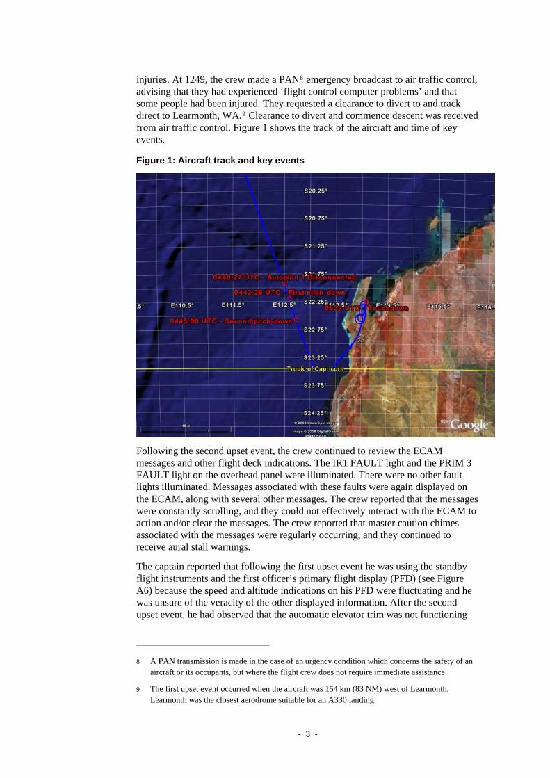
injuries. At 1249, the crew made a PAN8 emergency broadcast to air traffic control, advising that they had experienced ‘flight control computer problems’ and that some people had been injured. They requested a clearance to divert to and track direct to Learmonth, WA.9 Clearance to divert and commence descent was received from air traffic control. Figure 1 shows the track of the aircraft and time of key events.
Figure 1: Aircraft track and key events
Following the second upset event, the crew continued to review the ECAM messages and other flight deck indications. The IR1 FAULT light and the PRIM 3 FAULT light on the overhead panel were illuminated. There were no other fault lights illuminated. Messages associated with these faults were again displayed on the ECAM, along with several other messages. The crew reported that the messages were constantly scrolling, and they could not effectively interact with the ECAM to action and/or clear the messages. The crew reported that master caution chimes associated with the messages were regularly occurring, and they continued to receive aural stall warnings.
The captain reported that following the first upset event he was using the standby flight instruments and the first officer’s primary flight display (PFD) (see Figure A6) because the speed and altitude indications on his PFD were fluctuating and he was unsure of the veracity of the other displayed information. After the second upset event, he had observed that the automatic elevator trim was not functioning
8 A PAN transmission is made in the case of an urgency condition which concerns the safety of an
aircraft or its occupants, but where the flight crew does not require immediate assistance.
9 The first upset event occurred when the aircraft was 154 km (83 NM) west of Learmonth. Learmonth was the closest aerodrome suitable for an A330 landing.
- 3 -
and he had begun trimming the aircraft manually. He later disconnected the autothrust and flew the aircraft manually for the remainder of the flight.
The flight crew spoke to a flight attendant by interphone to get further information on the extent of the injuries. The flight crew advised the cabin crew that, due to the nature of the situation, they did not want them to get out of their seats, but to use the cabin interphones to gather the information. At 1254, after receiving advice from the cabin crew of several serious injuries, the crew declared a MAYDAY10 and advised air traffic control they had multiple injures on board, including a broken leg and some cases of severe lacerations.
The crew continued attempts to further evaluate their situation and, at 1256, contacted the operator’s maintenance watch unit11, located in Sydney, by SATPHONE to seek assistance. There were several subsequent communications during the flight between the flight crew and maintenance watch, who advised that the various faults reported by the crew were confirmed by data link, but that they were not able to diagnose reasons for the faults. During one of the conversations, maintenance watch suggested that the crew could consider switching PRIM 3 off, and this action was carried out. This action did not appear to have any effect on the scrolling ECAM messages, or the erratic airspeed and altitude information.
The crew conducted a visual descent via a series of wide left orbits, maintaining aircraft speed below 330 kts (maximum operating speed). They completed the approach checklist and conducted a flight control check above 10,000 ft. They were unable to enter an RNAV (GNSS)12 approach into the flight management computer; however, the aircraft was positioned at about 15 NM for a straight-in visual approach to runway 36. The precision approach path indicator (PAPI) was acquired at about 16 km (10 NM) and the aircraft landed without further incident at Learmonth at 1350.
Injuries to persons Table 1 presents summary information on the extent of passenger injuries in the standard format used in major aviation safety investigation reports. This information is preliminary and further information on the extent of passenger injuries is currently being gathered (see Ongoing Investigation Activities).
10 A MAYDAY transmission is made in the case of a distress condition and where the flight crew
requires immediate assistance.
11 Maintenance watch provides 24-hour assistance to enroute flight crews regarding technical issues.
12 RNAV (GNSS) approach: area navigation global navigation satellite system non-precision approach. Previously termed a ‘GPS approach’.
- 4 -
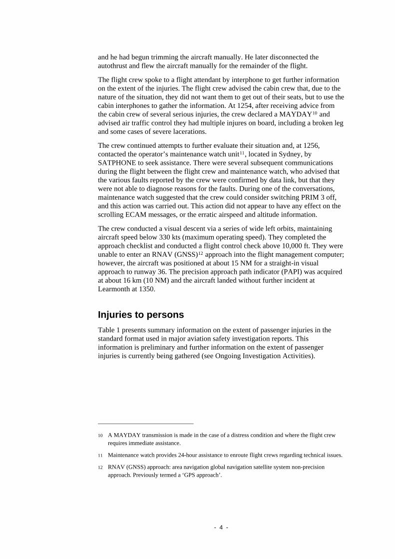
Table 1: Number and level of injuries
Injuries Crew Passengers Other Total
Fatal - - - -
Serious13 1 13 - 14
Minor / None 11 290 - 301
Total 12 303 - 315
Initial information provided to the Australian Transport Safety Bureau (ATSB) was that 14 people were taken by air ambulance to Perth. Injuries were considered serious, but not life threatening, and included concussion and broken bones. In addition, up to 30 other people attended hospital with possible concussion, minor lacerations and fractures, with up to a further 30 or so people with minor bruises and stiff necks who did not need to attend hospital.
Subsequent information indicates that one flight attendant and at least 13 passengers were admitted to hospital. The nature and extent of the injuries varied considerably, including injuries listed above and spinal injuries.
At the time of the first in-flight upset event, three flight attendants and the first officer were standing in the forward galley and one flight attendant had just left that galley. The first officer and two of the attendants received minor injuries and the other was uninjured. Four of the flight attendants were preparing to leave the crew rest area (four seats located near the Left 3 door), and all received minor injuries. A flight attendant standing in the rear galley received serious injuries.
Information has been obtained from over 10 per cent of the passengers to date. Based on this information, almost all of the passengers who were seated without seatbelts fastened received either serious or minor injuries during the first in-flight upset. Many of these passengers impacted the ceiling panels. Most of the passengers who had their seatbelts fastened were uninjured, although some received minor injuries. Passengers who were standing at the time of the first in-flight upset received either serious or minor injuries.
Damage to the aircraft No structural damage to the aircraft was found during an inspection at Learmonth (see Aircraft examination).
Inspection of the aircraft interior revealed damage mainly in the centre and rear sections of the passenger cabin. The level of damage varied significantly. Much of the damage was in the area of the personal service units above each passenger seat, and adjacent panels. The damage was typically consistent with that resulting from an impact by a person or object. There was evidence of damage above approximately 10 per cent of the seats in the centre section of the cabin, and above
13 Under the Transport Safety Investigation Regulations (2003), a serious injury is defined as ‘an
injury that requires, or would usually require, admission to hospital within 7 days after the day when the injury is suffered’. Consistent with the ICAO definition outlined in Annex 13 to the Chicago Convention, an accident is defined in the Transport Safety Investigation Act 2003 as an investigable matter involving an aircraft where a person dies or suffers a serious injury, or the aircraft is destroyed or seriously damaged.
- 5 -
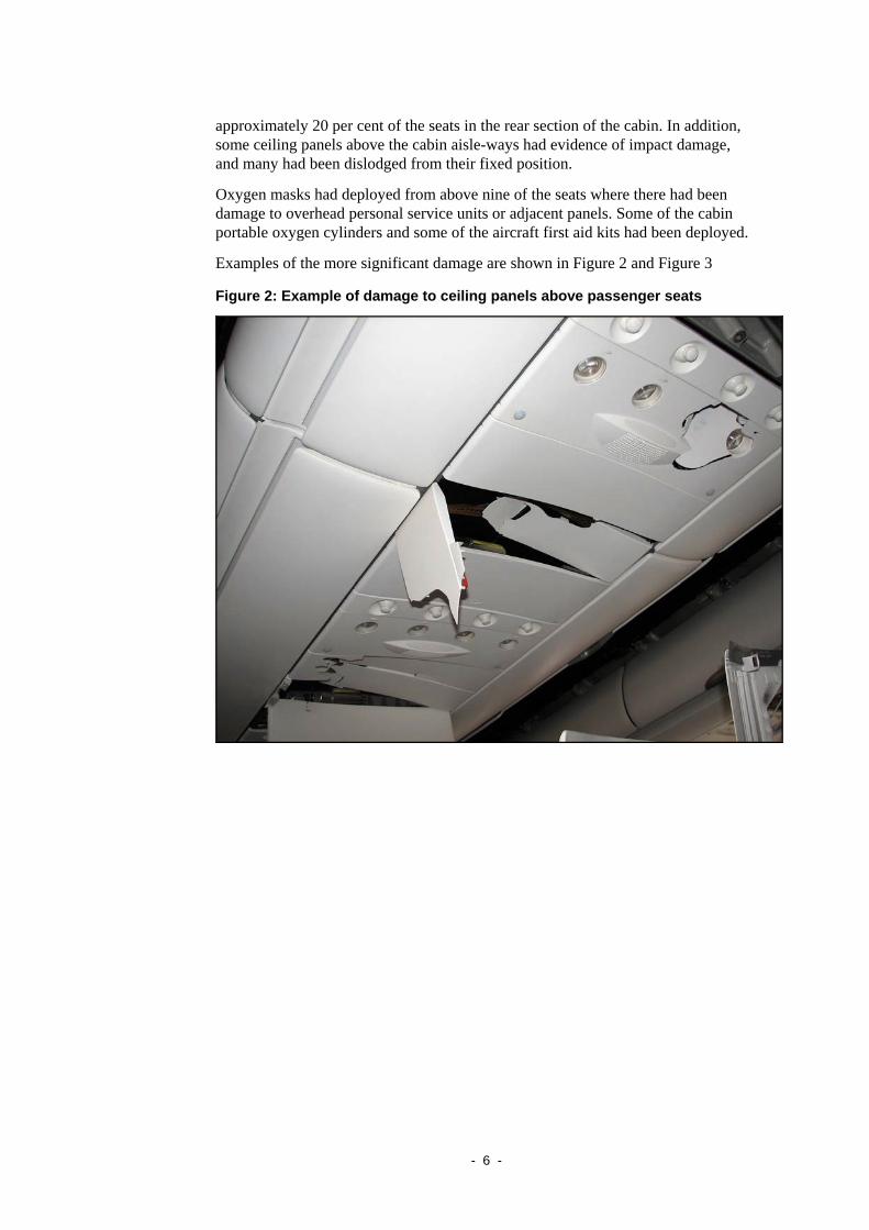
approximately 20 per cent of the seats in the rear section of the cabin. In addition, some ceiling panels above the cabin aisle-ways had evidence of impact damage, and many had been dislodged from their fixed position.
Oxygen masks had deployed from above nine of the seats where there had been damage to overhead personal service units or adjacent panels. Some of the cabin portable oxygen cylinders and some of the aircraft first aid kits had been deployed.
Examples of the more significant damage are shown in Figure 2 and Figure 3
Figure 2: Example of damage to ceiling panels above passenger seats
- 6 -
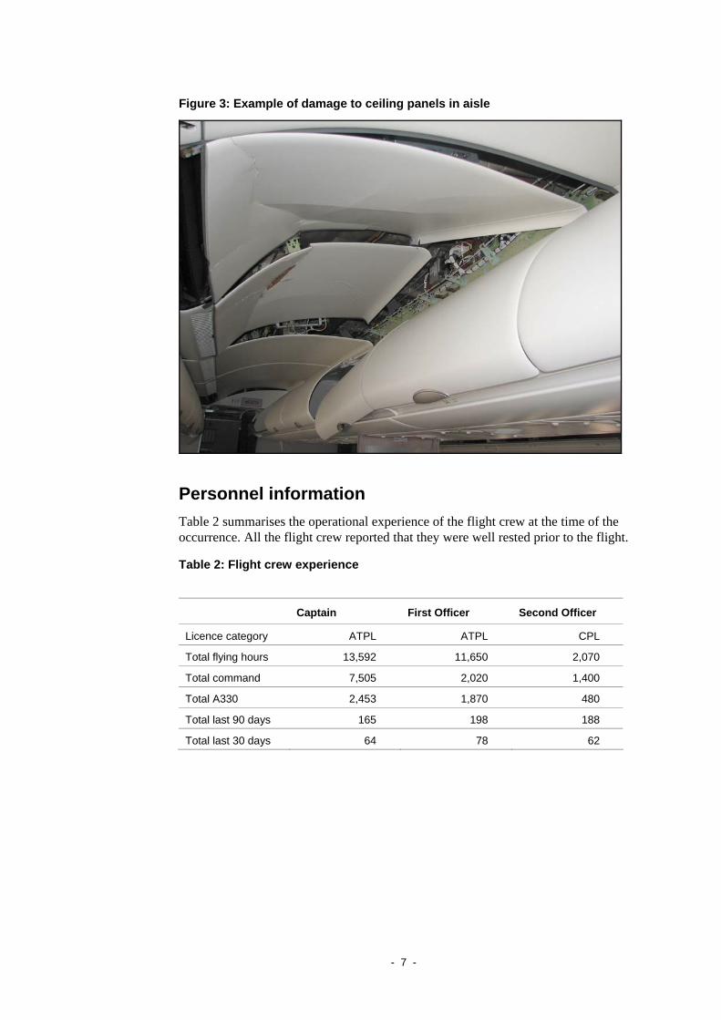
Figure 3: Example of damage to ceiling panels in aisle
Personnel information Table 2 summarises the operational experience of the flight crew at the time of the occurrence. All the flight crew reported that they were well rested prior to the flight.
Table 2: Flight crew experience
Captain First Officer Second Officer
Licence category ATPL ATPL CPL
Total flying hours 13,592 11,650 2,070
Total command 7,505 2,020 1,400
Total A330 2,453 1,870 480
Total last 90 days 165 198 188
Total last 30 days 64 78 62
- 7 -
Aircraft information
General information
Aircraft type: Airbus A330-303
Serial number: 0553
Year of manufacture: 2003
Registration: VH-QPA
Certificate of Registration: 31 October 2003
Certificate of Airworthiness: 26 November 200314
Total airframe hours: 20,040
Total airframe cycles: 3,740
Last ‘C’ maintenance check: 1-13 March 2008
The take-off weight of the aircraft was 207,065 kg. The weight of the aircraft and centre of gravity were within the prescribed limits.
Preliminary analysis of maintenance records for the aircraft and pertinent systems has been conducted. Initial indications are that the aircraft met all relevant airworthiness requirements.
Air data inertial reference units
Traditionally, airliner aircraft were equipped with separate inertial reference units and separate air data computers. Modern aircraft, such as the A330, combine the inertial reference unit and air data computer into a single unit called an air data inertial reference unit (ADIRU). VH-QPA was equipped with three ADIRUs (ADIRU 1, ADIRU 2 and ADIRU 315) as part of an air data and inertial reference system (ADIRS). Each ADIRU was divided in two parts:
• the air data reference (ADR) part, which supplied barometric altitude, speed, Mach, angle of attack and temperature
• the inertial reference (IR) part, which supplied attitude, flight path vector, track, heading, accelerations, angular rates, ground speed, vertical speed and aircraft position.
14 The aircraft was delivered to the operator as an A330-301 model in November 2003. The original
Certificate of Airworthiness was dated 26 November 2003. The aircraft was modified in December 2004 which changed the model from a -301 to a -303. A new Certificate of Airworthiness was issued on 10 December 2004 to reflect the correct model number.
15 Model name: LTN-101 Global Navigation Air Data Inertial Reference Unit (GNADIRU). Part Number: 465020-0303-0316. ADIRU 1 Serial Number 4167, ADIRU 2 Serial Number 4687, ADIRU 3 Serial Number 4663.
- 8 -
The ADIRUs received air data from the aircraft’s pitot probes, static pressure probes, angle-of-attack sensors, and total air temperature probes.
Further information on the ADIRUs and some other aircraft systems is provided in Appendix A.
Meteorological information The Bureau of Meteorology provided the following information regarding the weather conditions prevailing at the location and time of the occurrence:
• A ridge extended over southern Western Australia with a surface trough developing along the north and west coasts during the day.
• A sharpening upper level trough extended from the Great Australian Bight through Perth and into the Indian Ocean.
• Some thunderstorm activity was recorded from about Karratha to just north of Learmonth, with cloud tops to about flight level (FL) 330 (33,000 ft).
• The axis of a 120 kt sub-tropical jet stream lay north-west to south-east between Learmonth and Carnarvon at FL 400 (40,000 ft). A shear line was developing south of the jet-stream as the upper trough developed.
• Data obtained at 0600 UTC (1400 local time) on 7 October 2008 showed a shear line associated with the upper level trough well south of the jet stream. There was no evidence of any penetration of cold air under the jet stream that could have lead to increased vertical wind shear.
• Three model-generated forecasts predicted an area of moderate turbulence associated with the jet stream.
• At the time of the occurrence, the aircraft appeared to be in the vicinity of the sub-tropical jet stream, to the near north of a shear line and well south of any significant convection activity.
• Turbulence at a moderate or greater level was unlikely to have influenced the aircraft at the time of the occurrence.
Flight recorders
Overview
The aircraft was fitted with three flight recorders:
• a cockpit voice recorder (CVR)
• a flight data recorder (FDR)
• a quick access recorder (QAR).
The CVR and FDR are the so-called ‘black-boxes’ and are required by regulation to be installed on certain types of aircraft. Information recorded by the CVR and FDR is stored in crash-protected modules.
The QAR is an optional recorder that the operator has chosen to fit to all their A330 aircraft. Information recorded by the QAR is not crash-protected. As the name
- 9 -
suggests QARs allow quick access to flight data whereas FDRs require specialist downloading equipment. The parameters that are recorded by an FDR are defined by regulatory requirements. However, QAR systems can be configured by an operator to record different parameters. Operators routinely use QAR data for engineering system monitoring and fault-finding, incident investigation and flight operations quality assurance programs.
Recording system operation
CVR system
The CVR records the total audio environment in the cockpit area, which may include crew conversation, radio transmissions, aural alarms, control movements, switch activations, engine noise and airflow noise. The CVR installed in VH-QPA retained the last 2 hours of information in solid-state memory, operating on an endless-loop principle.
FDR system
The FDR records aircraft flight data and, like the CVR, operates on an endless-loop principle. The recording duration is required to be at least 25 hours and the FDR typically records when at least one engine is operating and stops recording 5 minutes after the last engine is shutdown. The FDR installed in VH-QPA recorded approximately 1,100 parameters and used solid-state memory as the recording medium.
QAR system
Like the FDR, the QAR16 records aircraft flight data. The QAR installed in VH-QPA stored data on a removable magneto-optical disk with a capacity of 230 Mbytes and recorded approximately 250 parameters. Airlines balance the logistics of handling large quantities of QAR disks with the benefits of obtaining the data as soon as possible after a flight has occurred. Typically most airlines will leave a disk inserted in the QAR for several days until the aircraft returns to a suitable maintenance base.
Recorder recovery
The Australian Transport Safety Bureau (ATSB) supervised the removal of the CVR, FDR and QAR disk from the aircraft in Learmonth and their dispatch to the ATSB’s technical facilities in Canberra.17 They were received in Canberra on 8 October 2008 and were replayed immediately. Preliminary FDR data was provided to the investigation team on 9 October 2008.
16 As the parameters recorded by the QAR were configurable by the airline, it is described as a
Digital ACMS Recorder (DAR) in Airbus terminology. To avoid confusion, the generic term QAR is used in this report. ACMS is an abbreviation for Aircraft Condition Monitoring System.
17 CVR details: Part Number 2100-1020-02, Serial Number 000252164. FDR details: Part Number 2100-4043-02, Serial Number 000428627.
- 10 -
Results
CVR
The entire 2 hours of recorded audio was successfully downloaded by ATSB investigators in Canberra. Analysis of the audio showed that power had been removed from the CVR soon after the aircraft arrived at the terminal in Learmonth. As a consequence, the CVR had retained the audio recorded during the accident sequence from prior to the initial autopilot disconnection and including both pitch-down events.
FDR
The FDR was downloaded by ATSB investigators in Canberra. The FDR had recorded over 217 hours of aircraft operation, comprising the accident flight and 24 previous flights. The oldest flight recorded was QF51 on 23 September 2008.
For the accident flight, continuous data from engine start on the ground in Singapore until after engine shutdown at Learmonth was successfully recovered. FDR data was used to produce a sequence of events (see below) and plots (refer to Appendix B). Figure B1 provides summary data for the whole flight, and Figures B2 and B3 provide more detailed data for the period covering the two in-flight upsets. Figures B4 and B5 provide specific information for each of the upsets.
QAR
Files stored on the QAR disk were recovered by the ATSB. Flight data from seven flights was successfully recovered. The flights recorded were:
• 4 October 2008: Sydney – Adelaide, Adelaide – Singapore
• 5 October 2008: Singapore – Perth, Perth – Singapore
• 6 October 2008: Singapore – Perth, Perth – Singapore
• 7 October 2008: Singapore – Learmonth
For the accident flight, continuous data from engine start on the ground in Singapore until after engine shutdown at Learmonth was successfully recovered.
Sequence of events
Table 3 provides a sequence of events prepared from data obtained from the aircraft’s FDR. Times are based on UTC. Local time is UTC plus 8 hours.
Table 3: Occurrence flight sequence of events
Time (UTC)
(hh:mm:ss)
Time relative to event (hh:mm:ss)
Event:
01:32:02 -03:10:23 Takeoff at Singapore
02:01:16 -02:41:09 Aircraft reached top of climb (37,000 ft or FL370)
04:40:28 -00:01:57 Autopilot 1 disconnected
04:40:28 -00:01:57 First master warning was recorded. Warnings
- 11 -
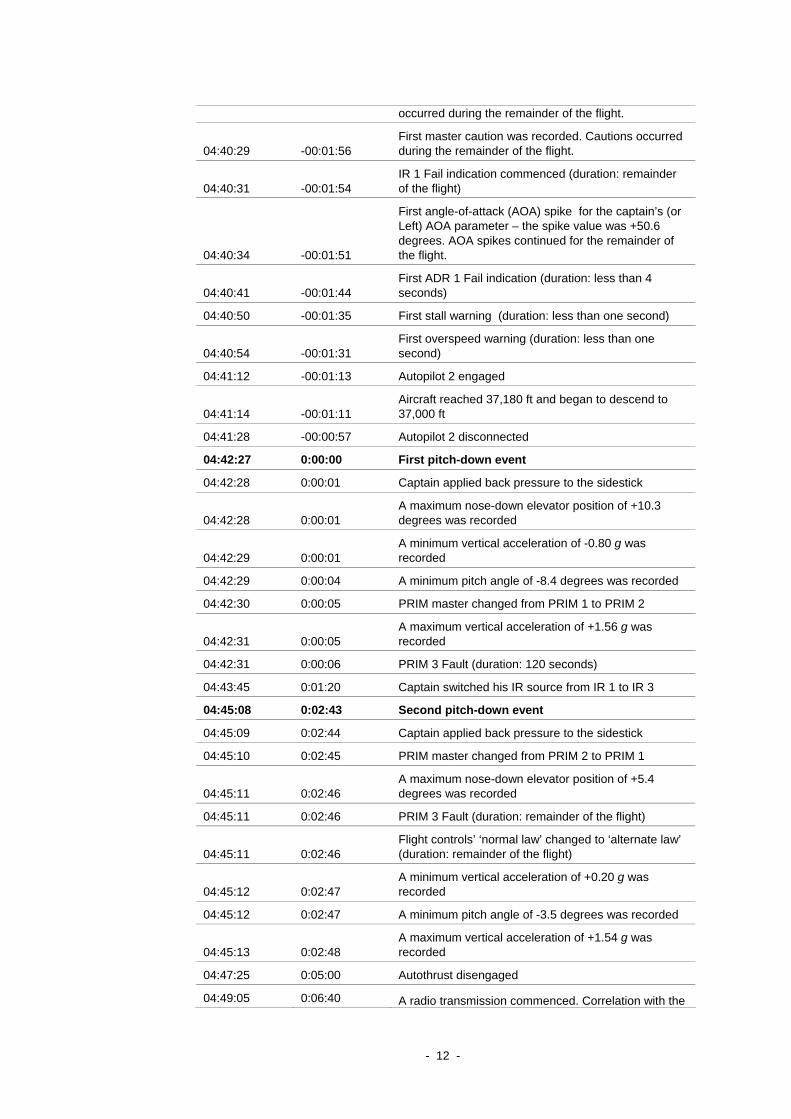
occurred during the remainder of the flight.
04:40:29 -00:01:56 First master caution was recorded. Cautions occurred during the remainder of the flight.
04:40:31 -00:01:54 IR 1 Fail indication commenced (duration: remainder of the flight)
04:40:34 -00:01:51
First angle-of-attack (AOA) spike for the captain’s (or Left) AOA parameter – the spike value was +50.6 degrees. AOA spikes continued for the remainder of the flight.
04:40:41 -00:01:44 First ADR 1 Fail indication (duration: less than 4 seconds)
04:40:50 -00:01:35 First stall warning (duration: less than one second)
04:40:54 -00:01:31 First overspeed warning (duration: less than one second)
04:41:12 -00:01:13 Autopilot 2 engaged
04:41:14 -00:01:11 Aircraft reached 37,180 ft and began to descend to 37,000 ft
04:41:28 -00:00:57 Autopilot 2 disconnected
04:42:27 0:00:00 First pitch-down event
04:42:28 0:00:01 Captain applied back pressure to the sidestick
04:42:28 0:00:01 A maximum nose-down elevator position of +10.3 degrees was recorded
04:42:29 0:00:01 A minimum vertical acceleration of -0.80 g was recorded
04:42:29 0:00:04 A minimum pitch angle of -8.4 degrees was recorded
04:42:30 0:00:05 PRIM master changed from PRIM 1 to PRIM 2
04:42:31 0:00:05 A maximum vertical acceleration of +1.56 g was recorded
04:42:31 0:00:06 PRIM 3 Fault (duration: 120 seconds)
04:43:45 0:01:20 Captain switched his IR source from IR 1 to IR 3
04:45:08 0:02:43 Second pitch-down event
04:45:09 0:02:44 Captain applied back pressure to the sidestick
04:45:10 0:02:45 PRIM master changed from PRIM 2 to PRIM 1
04:45:11 0:02:46 A maximum nose-down elevator position of +5.4 degrees was recorded
04:45:11 0:02:46 PRIM 3 Fault (duration: remainder of the flight)
04:45:11 0:02:46 Flight controls’ ‘normal law’ changed to ‘alternate law’ (duration: remainder of the flight)
04:45:12 0:02:47 A minimum vertical acceleration of +0.20 g was recorded
04:45:12 0:02:47 A minimum pitch angle of -3.5 degrees was recorded
04:45:13 0:02:48 A maximum vertical acceleration of +1.54 g was recorded
04:47:25 0:05:00 Autothrust disengaged
04:49:05 0:06:40 A radio transmission commenced. Correlation with the
- 12 -
CVR showed that this was the PAN transmission.
04:54:24 0:11:59 A radio transmission commenced. Correlation with the CVR showed that this was the Mayday transmission.
05:32:08 0:49:43 Aircraft touched down at Learmonth
05:42:12 1:02:47 Aircraft stopped at terminal
05:50:32 1:08:07 Power removed from FDR
FDR information related to ADIRUs
ADIRU 1 was connected to the captain’s displays and ADIRU 2 to the first officer’s displays. ADIRU 3 can be switched to either the captain’s or first officer’s position in the case of a failure of ADIRU 1 or 2.
Air data reference parameters that were recorded by the FDR included:
• pressure altitude
• computed airspeed
• mach number
• static air temperature
• angle of attack (AOA)18 from both the captain’s and first officer’s sensors (that is, Left and Right systems).
Inertial reference parameters that were recorded by the FDR included:
• pitch angle
• roll angle
• groundspeed
• inertial vertical speed
• drift angle
• heading
• latitude and longitude.
Some parameters required inputs from both the ADR and IR functions. They included wind speed and wind direction.
IR 1 and ADR 1 Fail indications
At 0440:28 UTC (1240:28 local time), autopilot 1 disconnected and the inertial reference system (IR) function of ADIRU 1 began to indicate ‘Fail’ (04:40:31). As the IR Fail indication is only sampled once every 4 seconds, it may have preceded the autopilot disconnection. A discrepancy between the command (COM) and monitor (MON) channels of PRIM 1 is likely to have automatically disconnected the autopilot.
The IRS ‘Fail’ indication for ADIRU 1 continued for the remainder of the flight. ADIRU 2 and ADIRU 3 appear to have operated normally throughout the flight.
18 ‘Angle of attack’ refers to the angle between the wing chord (centreline) and the airflow direction.
- 13 -
The first ADR 1 ‘Fail’ indication began at 0440:41 UTC. This indication lasted for less than 4 seconds. In total, 20 ADR 1 ‘Fail’ indications were recorded before the aircraft touched down at Learmonth. As the ADR 1 ‘Fail’ parameter is sampled once every 4 seconds, a brief ADR 1 fail indication may not necessarily be sampled and recorded. As a result, the number of actual ADR 1 ‘Fail’ indications may have been larger than the number recorded by the FDR.
Spikes in FDR and QAR data
For an A330, during all phases of flight, the typical operational range of AOA is +1 degree to +10 degrees. In cruise, a typical AOA is +2 degrees.
The first AOA Left spike19 occurred at 0440:34 UTC. AOA Left values changed from +2.1 degrees to +50.6 degrees and back to +2.1 degrees over three successive samples. Forty-two AOA Left spikes were recorded before the aircraft touched down at Learmonth. As AOA Left is sampled once per second, a spike may not necessarily be sampled and recorded. As a result, the number of actual AOA Left spikes may have been larger than the number recorded.
Spikes were also evident in the following parameters:
• pressure altitude
• computed airspeed
• mach number
• static air temperature
• pitch angle
• roll angle
• wind speed
• wind direction.
Effects of the spikes on failure indications
A stall warning parameter was recorded by the FDR. The first stall warning occurred at 0440:50 UTC and numerous stall warnings were recorded from this time until 0512:00 UTC when the aircraft was descending through an altitude of 12,400 ft. As the stall warning parameter is sampled once per second, a brief warning may not necessarily be sampled and recorded. As a result, the number of actual stall warnings received by the crew may have been larger than the number recorded. Examination of other recorded parameters indicated that the stall warnings were spurious.
An overspeed parameter was recorded by the FDR. The first overspeed warning occurred at 0440:54 UTC and numerous warnings were recorded from this time until 0502:01 UTC when the aircraft was descending through an altitude of 25,400 ft. As the overspeed warning parameter is sampled once per second, a brief warning may not necessarily be sampled and recorded. As a result, the number of actual overspeed warnings received by the crew may have been larger than the number
19 A spike is a short duration transient which exceeds the normal value by a large amount.
- 14 -
recorded. Examination of other recorded parameters indicated that the overspeed warnings were spurious.
ADIRU 1 normally supplies the captain’s PFD with IR and ADR parameters. The spikes in many of these parameters would have led to fluctuations and loss of data on the captain’s PFD. At 0443:45 UTC, the source of IR parameters for the captain’s PFD was switched from IR 1 (ADIRU 1) to IR 3 (ADIRU 3). This action should have provided valid IR parameters; however ADR parameters were still being sourced from ADR 1 (ADIRU 1).
A master caution aural alert (a single chime) occurs when certain types of failure messages appear on the ECAM. Separate master caution parameters for the captain and first officer are recorded by the FDR. The first master caution occurred at 0440:29 UTC and repetitive master cautions were recorded from this time until the FDR was powered down on the ground at Learmonth.
Aircraft pitch-downs
Under the aircraft’s normal flight control laws, the PRIMs provide protection against exceeding a pre-defined safe flight envelope. This includes high angle-of-attack protection. To prevent the safe flight envelope from being exceeded, the PRIMs can automatically command control surface movements.
The FDR showed that the first pitch-down occurred at 04:42:27 UTC. Recorded events that were closely associated in time with this event included:
• a spike in AOA Left was recorded by the FDR (04:42:26 UTC, magnitude of +50.6 degrees)
• a F/CTL PRIM 1 PITCH FAULT was logged on the post flight report (04:42 UTC)20
• PRIM master changed from PRIM1 to PRIM 2 (04:42:30).
The FDR showed that the second pitch-down occurred at 04:45:08 UTC. Recorded events that were closely associated in time with this event included:
• a spike in AOA Left was recorded by the FDR (04:45:07 UTC, magnitude of +50.6 degrees)
• a F/CTL PRIM 2 PITCH FAULT was logged on the post flight report (04:45 UTC)
• PRIM master changed from PRIM2 to PRIM 1 (04:45:10 UTC)
• flight controls: ‘normal law’ changed to ‘alternate law’ (04:45:11 UTC).
The investigation is continuing to examine the influence spikes in ADIRU parameters had on the performance of the PRIMs.
20 The post flight report (PFR) was downloaded from the central maintenance computer on board the
aircraft. It provides times (to the nearest minute) of various faults and events. F/CTL PITCH FAULTS are parameters which were not recorded on the FDR.
- 15 -
Aircraft examination
Structural examination
Visual inspection of the aircraft found no missing or loose fasteners, no creases or folds in the fuselage skin and no signs of distress to any of the fuselage, wing or empennage skin, fairing panels or flight controls.
The FDR data showed that the peak g loadings during the flight were +1.56 g and - 0.80 g, with almost no lateral g loading. The conditional inspection section of the Aircraft Maintenance Manual (AMM) (Section 05-51-17, Inspections after flight in excessive turbulence or in excess of VMO) defined the normal flight operating range as -1.0 g to +2.5 g. Aircraft operation within this environment did not require additional inspections. Based on the review of the FDR data, the aircraft manufacturer asked for a visual inspection of the elevator servo-control attachment fittings. This inspection found no problems.
Cargo hold inspection
Inspection of the cargo area found all cargo was loaded in the correct position as recorded on the load manifest for the flight and no load shift was evident. All of the cargo containers and palletised cargo remained properly secured by the integral cargo restraint systems built into the floor of the cargo holds. Each individual freight container and pallet was also examined for load shift or break out of individual items from within each unit. None was evident. After removal of the cargo, the aircraft hold’s structure and restraint systems were inspected for damage which might be attributed to the event. No anomalies were found.
Once removed from the aircraft, and under the supervision of Australian Quarantine and Customs officers, the cargo was inspected for items which might be possible sources of electronic or electromagnetic interference. None could be identified.
Wiring examinations
Due to the level of damage to ceiling panels in the cabin, all the ceiling panels were removed and wiring looms were visually inspected. No defects were observed.
After the aircraft had been ferried to a maintenance base, the operator conducted precautionary checks of the aircraft’s ADIRU interface wiring. The checks involved continuity, short circuit, electrical bonding and shielding tests. No problems were found.
Data downloads from aircraft systems
Based on an examination of the FDR data, the aircraft manufacturer recommended removing ADIRU 1 and the number-1 probe heat computer (PHC)21 before conducting any data downloads or testing of the aircraft’s systems. Replacement
21 A PHC fault was recorded on an initial download of maintenance data. On further analysis of the
available information, this indicated fault was considered spurious.
- 16 -
units were then installed and maintenance data downloaded from the following aircraft equipment and systems:
• electronic flight control system (including the PRIMs, flight control secondary computers, flight control data concentrators and flight management guidance envelope computers)
• autoflight system
• air data and inertial reference system
• probe heat computers
• multi-mode receivers
• electrical power generation system.
A number of faults attributed to various systems were recorded. The downloaded data was retained by the ATSB for detailed analysis to identify primary source(s) of the faults.
System testing
After data was downloaded, operational tests were performed on the following aircraft systems in accordance with the aircraft manufacturer's recommended maintenance procedures:
• electronic flight control system
• inertial reference system
• air data reference system
• probe heat computers
• multi-mode receivers
• flight guidance computers
• electrical power generation system
• elevator hydraulic actuation and pitch control.
A fault was identified with the elevator hydraulic control, but this was considered by the aircraft manufacturer to be unrelated to the circumstances of the occurrence. The fault had a known cause that is only triggered under a very specific set of circumstances, different to those seen during the occurrence. The aircraft systems passed all other tests.
Previous occurrences Most components on modern aircraft, including ADIRUs, are highly reliable. There have been a small number of occasions where ADIRUs of different types made by different manufacturers have had some form of failure. However, it is extremely rare for any such failures to have an undesirable effect on an aircraft’s flight controls.
The ATSB investigated an in-flight upset occurrence related to an ADIRU failure on a Boeing 777-200 aircraft, which occurred on 1 August 2005, 240 km north-west of Perth. The ADIRU on that aircraft was made by a different manufacturer and of a
- 17 -

different type to that on VH-QPA. Further details of that investigation can be found on the ATSB web site.22
Airbus has reported that it is unaware of any previous occurrences where an ADIRU failure on one of its aircraft has resulted in undesirable elevator commands.
22 See http://www.atsb.gov.au/publications/investigation_reports/2005/AAIR/aair200503722.aspx.
- 18 -
ONGOING INVESTIGATION ACTIVITIES
Aircraft systems Analysis of the aircraft’s systems and recorded data is ongoing and will include the following activities:
• Data will be downloaded from each of the ADIRUs, and then each unit will be subject to detailed examination and testing at the ADIRU manufacturer’s facilities in the US. The plan for these activities is being finalised and is expected to be conducted from mid November 2008. The download, examination and testing will be attended by representatives of the ATSB, the French Bureau d’Enquêtes et d’Analyses pour la sécurité de l’aviation civile (BEA), the US National Transportation Safety Board (NTSB), the aircraft manufacturer, the ADIRU manufacturer, and the operator.
• Subject to the results of the ADIRU downloads, examinations and tests, examination of other aircraft components, such as the three PRIMs, may be conducted.
• The investigation will review the aircraft’s ADIRU data monitoring capability and its management of anomalous ADIRU data, including flight deck indications.
• The investigation will review records of previous occurrences involving ADIRU failures (which did not result in in-flight upsets) and previous occurrences where large numbers of spurious ECAM messages were generated.
The ATSB has received many suggestions from members of the public to consider the effect of various external sources of electromagnetic interference on the aircraft, particularly any transmissions by the Harold E. Holt very low frequency transmitter near Exmouth, WA. Initial analysis suggests it is unlikely that any transmissions from this facility could affect systems on board an aircraft flying near the vicinity. However, further assessment of this possibility and other possible sources of external electromagnetic interference will be examined.
Data is also being gathered from passengers regarding the nature of any portable electronic devices that were in operation at the time of the upsets. Initial analysis suggests that it is unlikely any such devices could affect systems in the manner which occurred on the occurrence flight. However, further examination of this possibility will also be conducted.
Cabin safety Interviews have been conducted with all of the cabin crew and some of the passengers who were seriously injured. Further interviews will be conducted to determine the sequence of events in the cabin and the factors associated with any injuries.
A passenger questionnaire has been developed and distribution of the questionnaire commenced on 28 October 2008 by email. The questionnaire asks passengers for their observations during the upset events, as well as asking questions on safety
- 19 -
information, use of seatbelts, injuries and use of personal electronic devices. It is intended that all passengers will be provided with the questionnaire.23
Additional cabin safety work will include analysis of the interviews and surveys to determine any patterns related to the occurrence or severity of injuries. Other activities will include a review of relevant aviation industry requirements regarding the use of seatbelts.
Flight recorders Examination of CVR, FDR and QAR information is on-going and will include the following:
• analysis of CVR audio regarding aural warnings, crew actions, aircraft handling and crew/cabin communications during the pitch-down events and the subsequent approach and landing at Learmonth
• analysis of QAR data to assist in analysing the performance of aircraft systems
• analysis of FDR data to produce a detailed sequence of events and assist in analysing the performance of aircraft systems
• a review of the earlier flights recorded by the FDR and QAR for any evidence of anomalous performance of aircraft systems.
Other activities Collection and analysis of a range of standard information for an accident investigation of this nature is ongoing. This includes meteorological information, flight crew check and training records, flight crew and cabin crew rosters, flight crew and cabin crew procedures and training, and air traffic control response activities.
The ATSB is aware that a post-incident multi-agency debrief has been conducted. The debrief included representatives from all available private, government and non-government organisations involved in the emergency response to the accident and the Westralia Airports Corporation is coordinating actions from that meeting. The ATSB will review those outcomes in relation to information obtained at interviews and from responses to the passenger questionnaire.
23 Contact details for some passengers are incomplete. If any passenger has not received a
questionnaire, please contact the ATSB on 1 800 020 616 (or 61 2 6257 4150 from outside Australia) or via email to [email protected].
- 20 -
SAFETY ACTION
Aircraft manufacturerI On 14 October 2008, as soon as a preliminary analysis of the occurrence was conducted, Airbus published Operator Information Telex (OIT) / Flight Operations Telex (FOT) SE 999.0083/08/LB (‘A330 in-flight incident’). The telex was issued to Airbus operators, who were asked to distribute it to all A330/A340/A340-500/A340-600 flight crews without delay. The telex provided brief details known about the occurrence. It also provided operational recommendations applicable for A330/A340 aircraft fitted with Northrop-Grumman ADIRUs. The telex stated that, pending final resolution, Airbus would issue an OEB [Operations Engineering Bulletin] 74-1 that would instruct flight crew to select OFF the whole ADIRU in the case of an inertial reference (IR) failure, instead of switching OFF only the IR part.
On 15 October, OEB-A330- 74-1 was dispatched, applicable to all A330 aircraft fitted with Northrop-Grumman ADIRUs. The OEB stated that, in the event of a NAV IR FAULT (or an ATT red flag being displayed on either the captain’s or first officer’s PFD), the required procedure was for the crew to select OFF the relevant ADR and then select OFF the relevant IR. A compatible temporary revision was issued to the Minimum Master Equipment List at the same time.
Aircraft operator On 15 October 2008, in response to the Airbus releases, the operator issued Flight Standing Order 134/08 for its A330 operations. On 24 October 2008, this order was replaced by Flight Standing Order 136/08, which incorporated the material from the Airbus OEB. In addition, a program of focussed training during simulator sessions and route checks was initiated to ensure that flight crew undertaking recurrent or endorsement training were aware of the contents of the Flight Standing Order.
Seatbelt reminders In its media statements providing updates on the investigation on 8 and 10 October 2008, the ATSB noted that this accident served as a reminder to all people who travel by air of the importance of keeping seatbelts fastened at all times when seated in an aircraft.
On 27 October 2008, the Australian Civil Aviation Safety Authority issued a media release that stated that the occurrence was as a timely reminder to passengers to ‘remain buckled up when seated at all stages of flight’. The media release also highlighted the importance of passengers following safety instructions issued by flight crew and cabin crew, including watching and actively listening to the safety briefing given by the cabin crew at the start of each flight.
- 21 -

PAGE INTENTIONALLY BLANK
- 22 -
APPENDIX A: BACKGROUND INFORMATION ON AIRCRAFT SYSTEMS
This appendix provides general background information on some of the A330 systems. It is based on information contained in the operator’s A330 Flight Crew Operating Manual, Volume 1: Systems Description. The information is not exhaustive.
Flight control system
General information
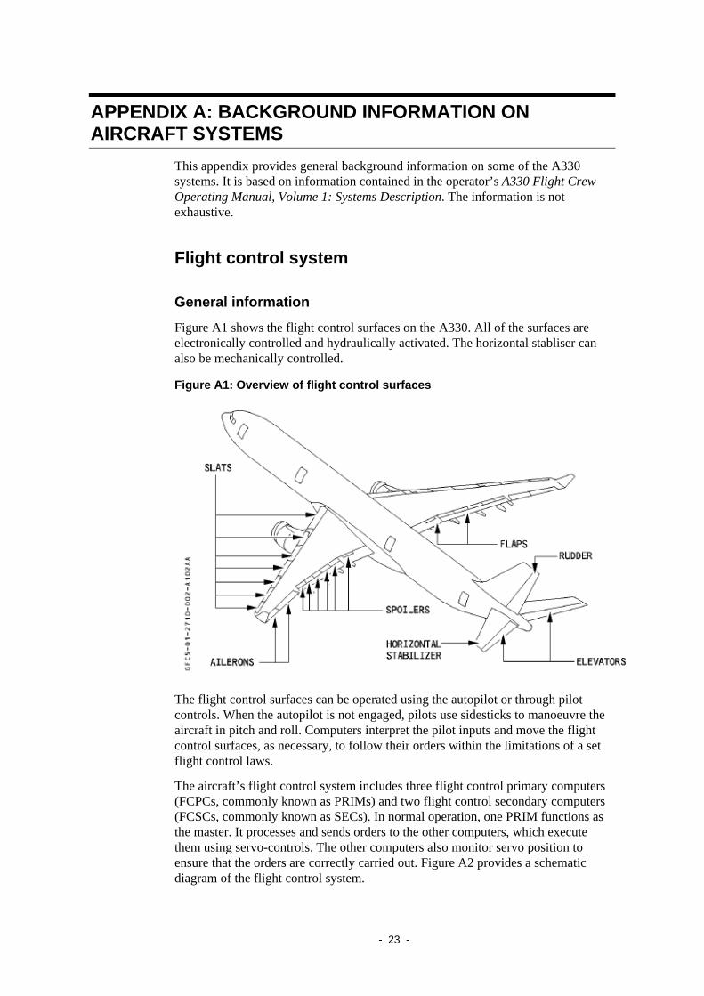
Figure A1 shows the flight control surfaces on the A330. All of the surfaces are electronically controlled and hydraulically activated. The horizontal stabliser can also be mechanically controlled.
Figure A1: Overview of flight control surfaces
The flight control surfaces can be operated using the autopilot or through pilot controls. When the autopilot is not engaged, pilots use sidesticks to manoeuvre the aircraft in pitch and roll. Computers interpret the pilot inputs and move the flight control surfaces, as necessary, to follow their orders within the limitations of a set flight control laws.
The aircraft’s flight control system includes three flight control primary computers (FCPCs, commonly known as PRIMs) and two flight control secondary computers (FCSCs, commonly known as SECs). In normal operation, one PRIM functions as the master. It processes and sends orders to the other computers, which execute them using servo-controls. The other computers also monitor servo position to ensure that the orders are correctly carried out. Figure A2 provides a schematic diagram of the flight control system.
- 23 -
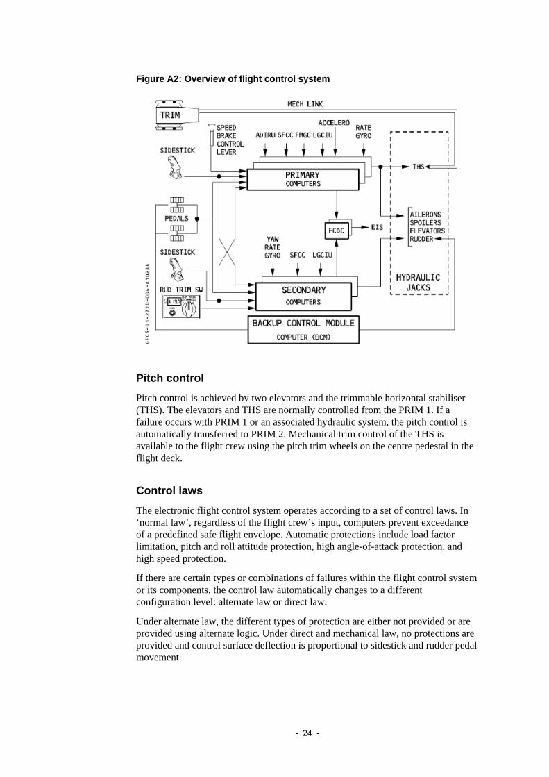
Figure A2: Overview of flight control system
Pitch control
Pitch control is achieved by two elevators and the trimmable horizontal stabiliser (THS). The elevators and THS are normally controlled from the PRIM 1. If a failure occurs with PRIM 1 or an associated hydraulic system, the pitch control is automatically transferred to PRIM 2. Mechanical trim control of the THS is available to the flight crew using the pitch trim wheels on the centre pedestal in the flight deck.
Control laws
The electronic flight control system operates according to a set of control laws. In ‘normal law’, regardless of the flight crew’s input, computers prevent exceedance of a predefined safe flight envelope. Automatic protections include load factor limitation, pitch and roll attitude protection, high angle-of-attack protection, and high speed protection.
If there are certain types or combinations of failures within the flight control system or its components, the control law automatically changes to a different configuration level: alternate law or direct law.
Under alternate law, the different types of protection are either not provided or are provided using alternate logic. Under direct and mechanical law, no protections are provided and control surface deflection is proportional to sidestick and rudder pedal movement.
- 24 -
Autopilot The autopilot stabilises the aircraft around its centre of gravity and commands the position of the flight control surfaces for pitch, roll and yaw to acquire and track a nominated flight path. The A330 has two autopilots. The flight crew can engage autopilot 1 or autopilot 2 by pressing the corresponding pushbutton.
The autopilot can be intentionally disengaged by the crew, or it could automatically disconnect as a result of a number of different conditions.
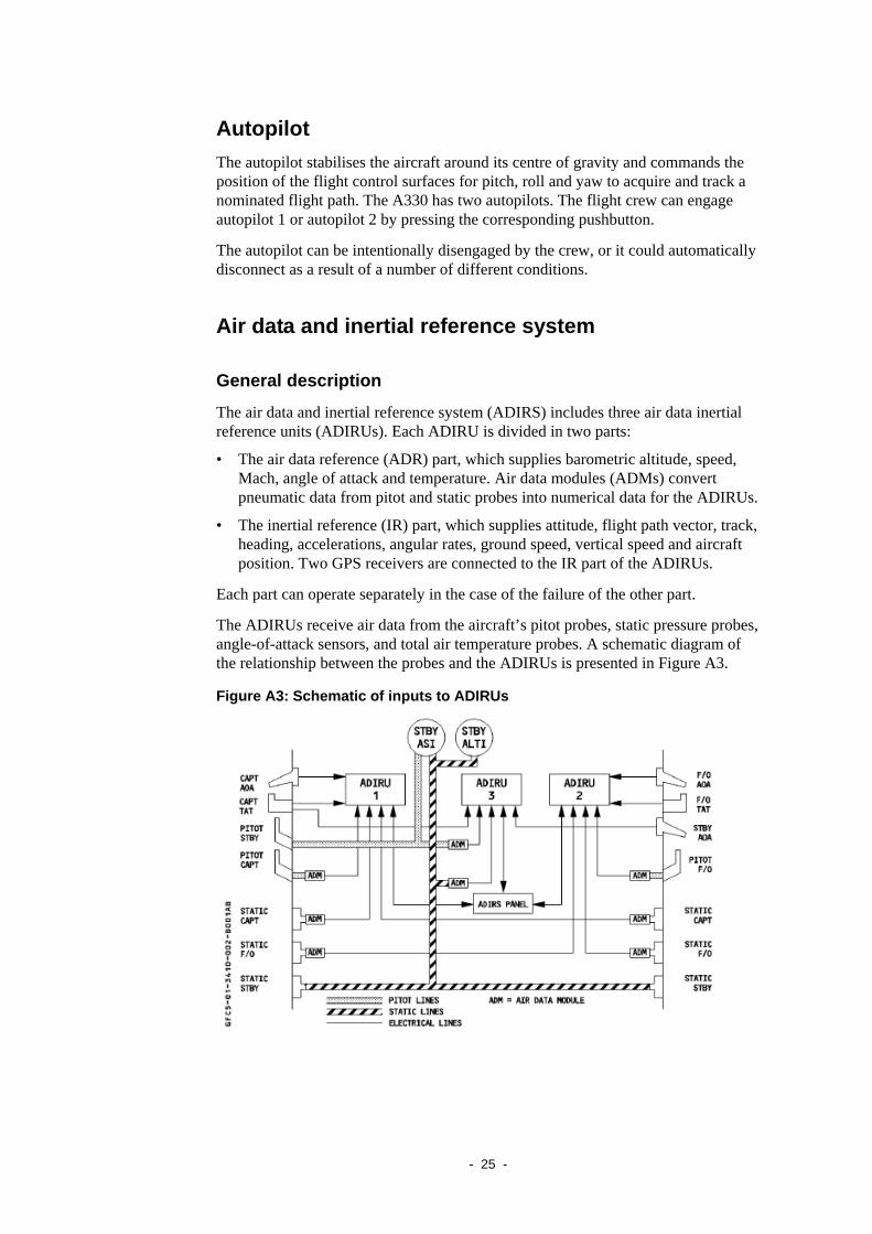
Air data and inertial reference system
General description
The air data and inertial reference system (ADIRS) includes three air data inertial reference units (ADIRUs). Each ADIRU is divided in two parts:
• The air data reference (ADR) part, which supplies barometric altitude, speed, Mach, angle of attack and temperature. Air data modules (ADMs) convert pneumatic data from pitot and static probes into numerical data for the ADIRUs.
• The inertial reference (IR) part, which supplies attitude, flight path vector, track, heading, accelerations, angular rates, ground speed, vertical speed and aircraft position. Two GPS receivers are connected to the IR part of the ADIRUs.
Each part can operate separately in the case of the failure of the other part.
The ADIRUs receive air data from the aircraft’s pitot probes, static pressure probes, angle-of-attack sensors, and total air temperature probes. A schematic diagram of the relationship between the probes and the ADIRUs is presented in Figure A3.
Figure A3: Schematic of inputs to ADIRUs
- 25 -
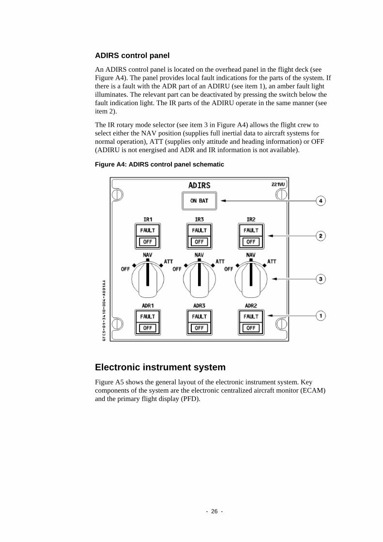
ADIRS control panel
An ADIRS control panel is located on the overhead panel in the flight deck (see Figure A4). The panel provides local fault indications for the parts of the system. If there is a fault with the ADR part of an ADIRU (see item 1), an amber fault light illuminates. The relevant part can be deactivated by pressing the switch below the fault indication light. The IR parts of the ADIRU operate in the same manner (see item 2).
The IR rotary mode selector (see item 3 in Figure A4) allows the flight crew to select either the NAV position (supplies full inertial data to aircraft systems for normal operation), ATT (supplies only attitude and heading information) or OFF (ADIRU is not energised and ADR and IR information is not available).
Figure A4: ADIRS control panel schematic
Electronic instrument system Figure A5 shows the general layout of the electronic instrument system. Key components of the system are the electronic centralized aircraft monitor (ECAM) and the primary flight display (PFD).
- 26 -
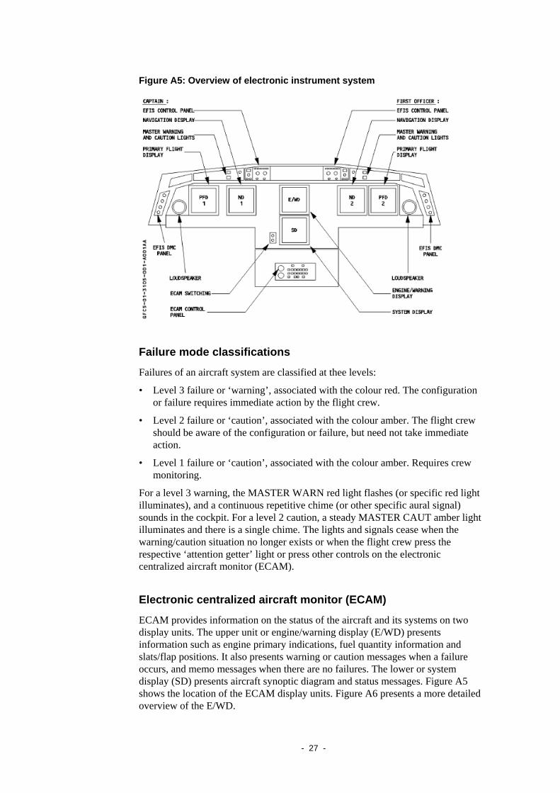
Figure A5: Overview of electronic instrument system
Failure mode classifications
Failures of an aircraft system are classified at thee levels:
• Level 3 failure or ‘warning’, associated with the colour red. The configuration or failure requires immediate action by the flight crew.
• Level 2 failure or ‘caution’, associated with the colour amber. The flight crew should be aware of the configuration or failure, but need not take immediate action.
• Level 1 failure or ‘caution’, associated with the colour amber. Requires crew monitoring.
For a level 3 warning, the MASTER WARN red light flashes (or specific red light illuminates), and a continuous repetitive chime (or other specific aural signal) sounds in the cockpit. For a level 2 caution, a steady MASTER CAUT amber light illuminates and there is a single chime. The lights and signals cease when the warning/caution situation no longer exists or when the flight crew press the respective ‘attention getter’ light or press other controls on the electronic centralized aircraft monitor (ECAM).
Electronic centralized aircraft monitor (ECAM)
ECAM provides information on the status of the aircraft and its systems on two display units. The upper unit or engine/warning display (E/WD) presents information such as engine primary indications, fuel quantity information and slats/flap positions. It also presents warning or caution messages when a failure occurs, and memo messages when there are no failures. The lower or system display (SD) presents aircraft synoptic diagram and status messages. Figure A5 shows the location of the ECAM display units. Figure A6 presents a more detailed overview of the E/WD.
- 27 -
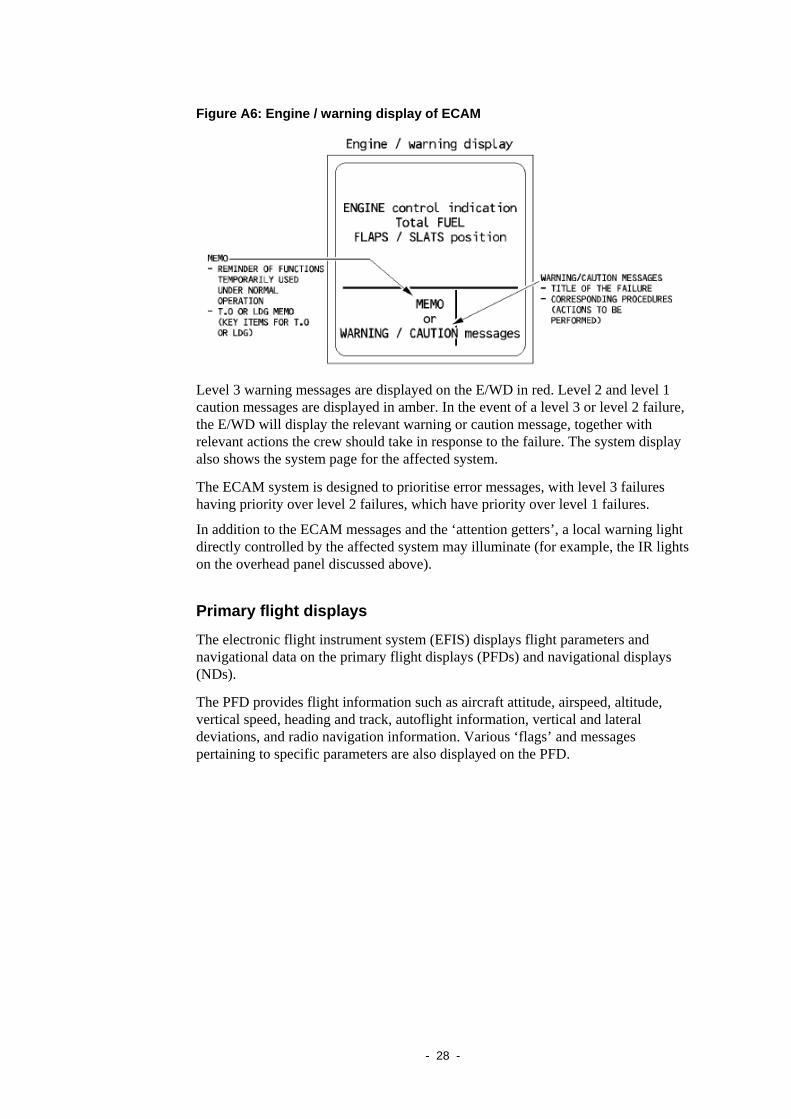
Figure A6: Engine / warning display of ECAM
Level 3 warning messages are displayed on the E/WD in red. Level 2 and level 1 caution messages are displayed in amber. In the event of a level 3 or level 2 failure, the E/WD will display the relevant warning or caution message, together with relevant actions the crew should take in response to the failure. The system display also shows the system page for the affected system.
The ECAM system is designed to prioritise error messages, with level 3 failures having priority over level 2 failures, which have priority over level 1 failures.
In addition to the ECAM messages and the ‘attention getters’, a local warning light directly controlled by the affected system may illuminate (for example, the IR lights on the overhead panel discussed above).
Primary flight displays
The electronic flight instrument system (EFIS) displays flight parameters and navigational data on the primary flight displays (PFDs) and navigational displays (NDs).
The PFD provides flight information such as aircraft attitude, airspeed, altitude, vertical speed, heading and track, autoflight information, vertical and lateral deviations, and radio navigation information. Various ‘flags’ and messages pertaining to specific parameters are also displayed on the PFD.
- 28 -
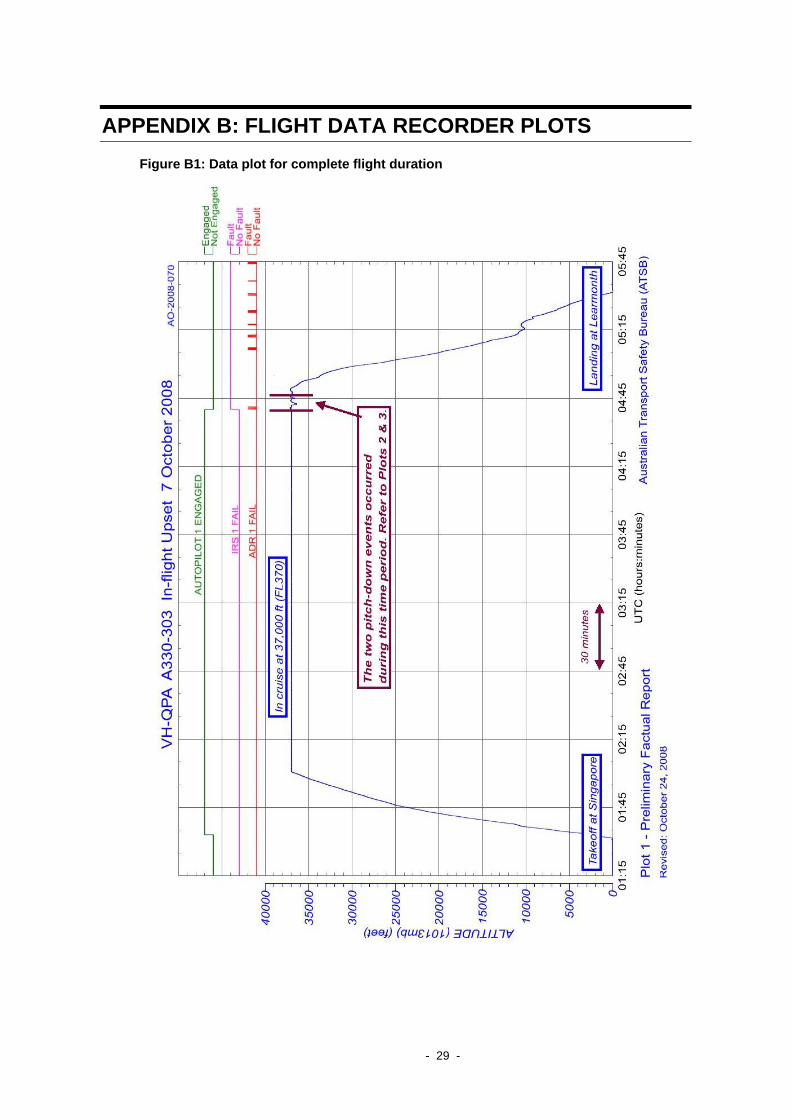
APPENDIX B: FLIGHT DATA RECORDER PLOTS Figure B1: Data plot for complete flight duration
- 29 -
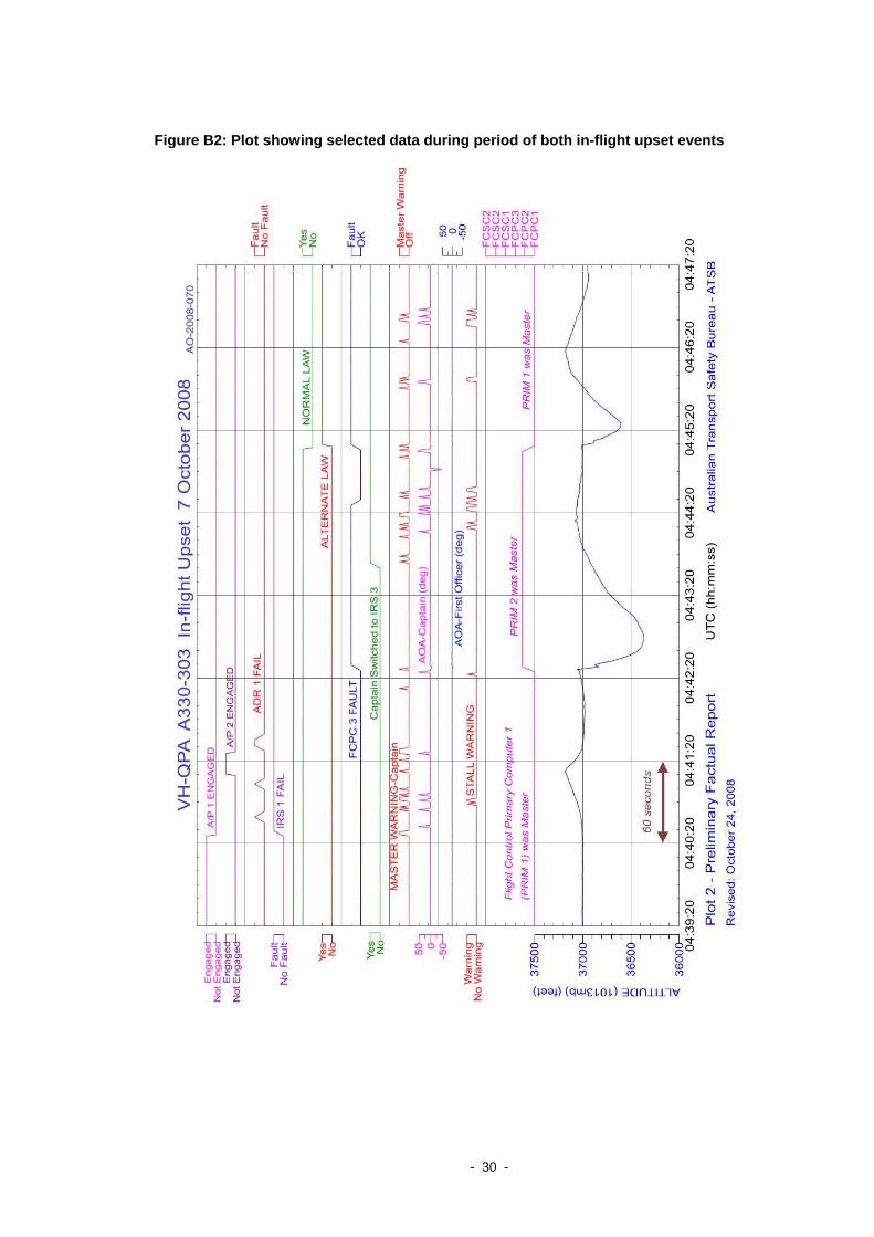
Figure B2: Plot showing selected data during period of both in-flight upset events
- 30 -
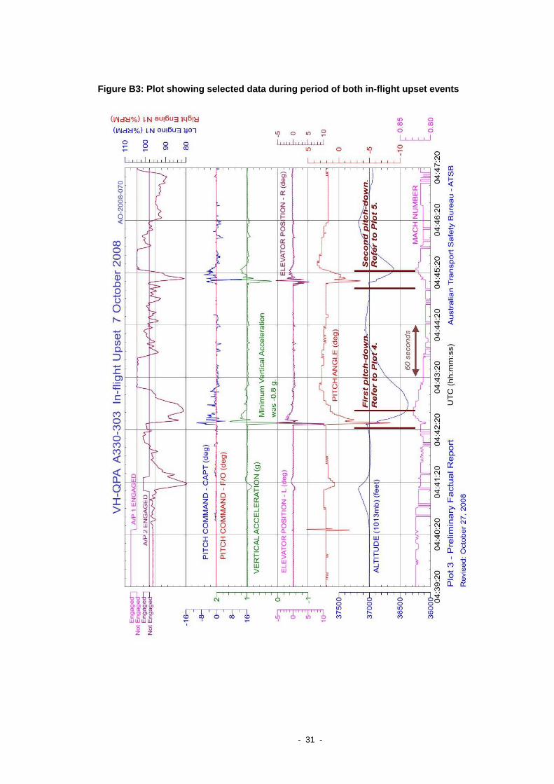
Figure B3: Plot showing selected data during period of both in-flight upset events
- 31 -
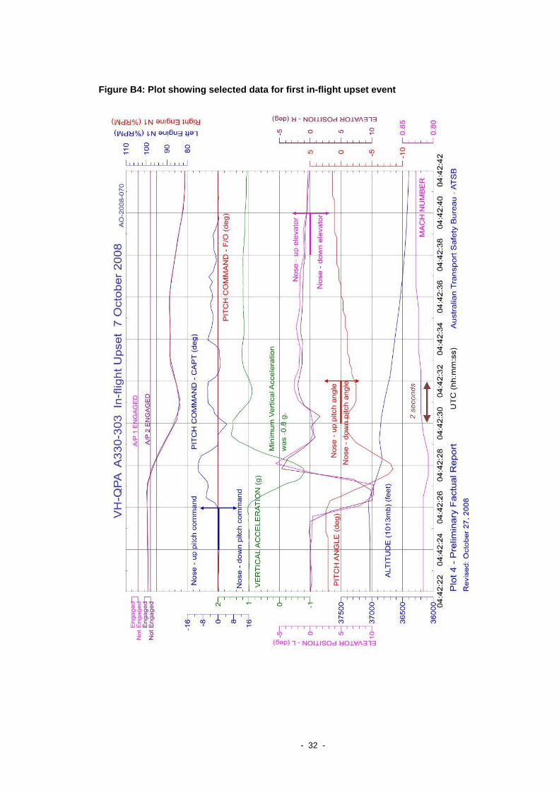
Figure B4: Plot showing selected data for first in-flight upset event
- 32 -
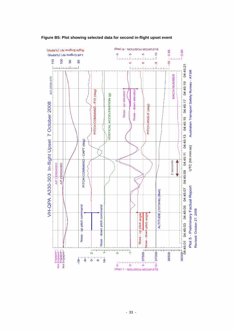
Figure B5: Plot showing selected data for second in-flight upset event
- 33 -