Embed Size (px)
Citation preview
ATSB TRANSPORT SAFETY REPORT Aviation Occurrence Investigation AO-2008-005
Final
Engine failure 15 km west of Townsville Airport, Qld
14 January 2008 VH-PSQ
Cessna Aircraft Company 208

- i -
ATSB TRANSPORT SAFETY REPORT Aviation Occurrence Investigation
AO-2008-005 Final
Engine failure 15 km west of Townsville Airport, Qld
14 January 2008 VH-PSQ
Cessna Aircraft Company 208
Released in accordance with section 25 of the Transport Safety Investigation Act 2003
- ii -
Published by: Australian Transport Safety Bureau Postal address: PO Box 967. Civic Square ACT 2608 Office location: 62 Northbourne Ave, Canberra City, Australian Capital Territory, 2601 Telephone: 1800 020 616, from overseas +61 2 6257 4150 Accident and incident notification: 1800 011 034 (24 hours) Facsimile: 02 6247 3117, from overseas +61 2 6247 3117 Email: [email protected] Internet: www.atsb.gov.au
© Commonwealth of Australia 2009.
This work is copyright. In the interests of enhancing the value of the information contained in this publication you may copy, download, display, print, reproduce and distribute this material in unaltered form (retaining this notice). However, copyright in the material obtained from other agencies, private individuals or organisations, belongs to those agencies, individuals or organisations. Where you want to use their material you will need to contact them directly.
Subject to the provisions of the Copyright Act 1968, you must not make any other use of the material in this publication unless you have the permission of the Australian Transport Safety Bureau.
Please direct requests for further information or authorisation to: Commonwealth Copyright Administration, Copyright Law Branch Attorney-General’s Department, Robert Garran Offices, National Circuit, Barton, ACT 2600 www.ag.gov.au/cca
ISBN and formal report title: see ‘Document retrieval information’ on page v
- iii -
CONTENTS
THE AUSTRALIAN TRANSPORT SAFETY BUREAU ................................ vii
FACTUAL INFORMATION ................................................................................ 9
History of the flight ........................................................................................... 9
Personnel information ....................................................................................... 9
Aircraft information .......................................................................................... 9 Engine details ..................................................................................... 10 Engine maintenance history ............................................................... 10
Meteorological information ............................................................................ 10
Examination of components ........................................................................... 11 Operator’s initial engine inspection .................................................... 11 Engine disassembly ............................................................................ 12 Technical examination of retained components ................................. 12 Forward oil pressure transfer elbow ................................................... 15
Organisational and management information ................................................. 15
ANALYSIS ............................................................................................................ 17
Engine failure mechanism ............................................................................... 17
CT blade failure mechanism ........................................................................... 17
Forward oil pressure transfer elbow................................................................ 17
Classification of operations ............................................................................. 17
FINDINGS ............................................................................................................. 19
Contributing safety factors .............................................................................. 19
Other safety factors ......................................................................................... 19
Other key findings........................................................................................... 19
SAFETY ACTION ............................................................................................... 21
Aircraft operator ............................................................................................. 21 Pilot situational awareness ................................................................. 21
APPENDIX A: TECHNICAL ANALYSIS REPORT ...................................... 23
SUMMARY .................................................................................................... 24
FACTUAL INFORMATION ......................................................................... 25 Introduction ........................................................................................ 25 Preliminary examination .................................................................... 25
- iv -
Scope of the examination ................................................................... 26 Engine details ..................................................................................... 27 Component examination ..................................................................... 27 Blade examination – compressor turbine ........................................... 36 Electron microscopy and micro-analysis ............................................ 39 Metallographic examination ............................................................... 43
ANALYSIS ..................................................................................................... 46 Engine failure mechanism .................................................................. 46 CT blade failure mechanism ............................................................... 46
FINDINGS ...................................................................................................... 47
APPENDIX B: SOURCES AND SUBMISSIONS ............................................. 49
Sources of information .................................................................................... 49
Submissions .................................................................................................... 49
- v -
DOCUMENT RETRIEVAL INFORMATION
Report No. AO-2008-005
Publication date 5 June 2009
No. of pages 46
ISBN 978-1-921602-54-2
Publication title Engine failure - 15 km west of Townsville Airport, Qld - 14 January 2008 - VH-PSQ, Cessna Aircraft Company 208
Prepared By Australian Transport Safety Bureau PO Box 967, Civic Square ACT 2608 Australia www.atsb.gov.au
Reference Number INFRA-08520
Abstract
On 14 January 2008 the pilot of a single-engine Cessna Aircraft Company 208 conducted a successful forced landing back onto the departure runway after the aircraft’s engine failed. The flight, with six passengers onboard, had earlier departed Townsville, Qld on a private Instrument Flight Rules (IFR) flight to Mt. Isa.
The evidence showed that the failure of the engine was precipitated by the fracture and separation of a single blade from the compressor turbine (CT) disc. The gross mechanical interference caused by the release of that blade into the confines of the turbine section contributed to the subsequent forced-fracture of the other CT blades and the downstream migration of blade debris. The remainder of the internal engine damage was identified as secondary damage as a result of that debris.
Damage to the area of crack initiation limited the extent of examination such that the root cause of fatigue initiation could not be established with certainty. However, from the available evidence, it was considered likely that the crack initiated at a localised area of stress concentration, such as may have arisen from the passage of foreign object debris through the engine, from handling or tooling damage sustained during a prior maintenance activity, or from the effects of an isolated blade casting anomaly that was not evident to the examination.

- vi -
- vii -
THE AUSTRALIAN TRANSPORT SAFETY BUREAU
The Australian Transport Safety Bureau (ATSB) is an operationally independent multi-modal bureau within the Australian Government Department of Infrastructure, Transport, Regional Development and Local Government. ATSB investigations are independent of regulatory, operator or other external organisations.
The ATSB is responsible for investigating accidents and other transport safety matters involving civil aviation, marine and rail operations in Australia that fall within Commonwealth jurisdiction, as well as participating in overseas investigations involving Australian registered aircraft and ships. A primary concern is the safety of commercial transport, with particular regard to fare-paying passenger operations.
The ATSB performs its functions in accordance with the provisions of the Transport Safety Investigation Act 2003 and Regulations and, where applicable, relevant international agreements.
Purpose of safety investigations
The object of a safety investigation is to enhance safety. To reduce safety-related risk, ATSB investigations determine and communicate the safety factors related to the transport safety matter being investigated.
It is not the object of an investigation to determine blame or liability. However, an investigation report must include factual material of sufficient weight to support the analysis and findings. At all times the ATSB endeavours to balance the use of material that could imply adverse comment with the need to properly explain what happened, and why, in a fair and unbiased manner.
Developing safety action
Central to the ATSB’s investigation of transport safety matters is the early identification of safety issues in the transport environment. The ATSB prefers to encourage the relevant organisation(s) to proactively initiate safety action rather than release formal recommendations. However, depending on the level of risk associated with a safety issue and the extent of corrective action undertaken by the relevant organisation, a recommendation may be issued either during or at the end of an investigation.
The ATSB has decided that when safety recommendations are issued, they will focus on clearly describing the safety issue of concern, rather than providing instructions or opinions on the method of corrective action. As with equivalent overseas organisations, the ATSB has no power to implement its recommendations. It is a matter for the body to which an ATSB recommendation is directed (for example the relevant regulator in consultation with industry) to assess the costs and benefits of any particular means of addressing a safety issue.
About ATSB investigation reports: How investigation reports are organised and definitions of terms used in ATSB reports, such as safety factor, contributing safety factor and safety issue, are provided on the ATSB web site www.atsb.gov.au

- viii -
- 9 -
FACTUAL INFORMATION
History of the flight On 14 January 2008, the pilot of a single-engine Cessna Aircraft Company 208 (Cessna 208) aircraft, registered VH-PSQ, departed Townsville Airport on a private category, prisoner transfer flight to Mt. Isa, Qld with six passengers onboard. At about 1035 Eastern Standard Time1, when the aircraft was reported to be between 5,000 to 6,000 ft above mean sea level (AMSL), about 8 NM (15 km) west of Townsville, and in Instrument Meteorological Conditions (IMC)2, the pilot felt a vibration that lasted for about 5 seconds. Shortly after, there was a significant loss of engine power.
The pilot reported that, in response, he advanced the emergency lever3, but with no effect. He then attempted unsuccessfully to restart the engine. The pilot then noticed smoke coming from the engine and secured the engine by feathering the propeller4 and cutting off the fuel supply to the engine.
The pilot declared a MAYDAY5 and the Townsville Approach controller assisted the pilot with positional and other information. Shortly after, the pilot became visual, and determined that he had sufficient height to attempt a landing on Townsville runway 01.
Personnel information The pilot held an Air Transport Pilots Licence (Aeroplane) (ATPL(A)), a Command (single-engine aeroplane) Instrument Rating and a Class 1 medical certificate. He was endorsed on the Cessna 208 and successfully completed a company base check and instrument flight test on 1 August 2007 in the incident aircraft.
Aircraft information The aircraft was manufactured in 1992 and had operated for a total of 9,292 hours at the time of the engine failure. The aircraft was fitted with a single Pratt & Whitney Canada (PWC) PT6A-114 turboprop engine, driving a McCauley model 3GFR34C703 variable pitch propeller.
1 The 24-hour clock is used in this report to describe the local time of day Eastern Standard Time
(EST), as particular events occurred. Eastern Standard Time was Coordinated Universal Time (UTC) + 10 hours.
2 Weather conditions that were less than those necessary for flight in accordance with the visual flight rules (VFR).
3 The emergency lever allowed a pilot to manually maintain the fuel flow to the engine in the event of a failure within the fuel control unit (FCU).
4 Turning an aircraft’s propeller blades to their feathering angle in response to an engine failure or other apparent malfunction, in order to minimise drag and prevent further damage.
5 International call for urgent assistance.
- 10 -
Engine details
The PWC PT6A-114 engine was a light-weight, free-turbine, turboprop engine. The engine included a four-stage, combined axial/centrifugal compressor, with a single-stage axial compressor turbine (CT) and an independent, single-stage axial power turbine (PT). The PT drove the propeller via a reduction gearbox. The engine was rated at 477 kW (600 shp).
At the time of the failure, the engine had accrued a total of 9,041 hours time since new (TSN), and 2,007 hours time since overhaul (TSO) in November 2003.
Engine maintenance history
The maintenance records for the engine showed that all of its CT blades and shroud segments were replaced with new components during the November 2003 engine overhaul.
During a scheduled engine inspection in February 2006, at about 990 engine hours prior to the engine failure, foreign object damage (FOD) was found on the first stage axial compressor. That damage was found to be within the acceptable limits as specified in the engine manufacturer’s maintenance manual. In accordance with the requirements of that manual, a 100-hourly repetitive inspection of the damage was initiated by the aircraft maintainer and included in the aircraft’s maintenance release. Ten repetitive inspections were carried out over a period of 820 engine hours from the identification of the FOD damage, with no change to the damage noted.
The last engine hot-section inspection (HSI)6 was completed in July 2007, at 8,826 hours TSN. Maintenance activity carried out on the engine during that inspection included a repair to the combustion liner, a CT shroud segment grind7, and stop-drilling8 of cracks within the combustion chamber exit ducts. The engine failure occurred 215 hours after the HSI.
Meteorological information The Bureau of Meteorology (BOM) area forecast9 for the departure predicted scattered showers, rain areas and isolated thunderstorms with low cloud and reduced visibility associated with a trough in the north of the area.
At about the time of the incident, a SPECI10 was issued for Townsville Airport that reported a southerly wind at 7 kts (13 km/h), a visibility of 4,000 m and light
6 A prescribed periodic inspection of the engine combustion and turbine components. 7 The segments have sufficient material thickness to allow grinding during their service life to
maintain correct CT blade tip clearance. That grinding/measuring process required the removal and re-installation of the CT disc a number of times.
8 A maintenance activity whereby hole/s are drilled at the leading edge of any cracks, in order to reduce the stress concentration and thus the likelihood of continued crack growth.
9 For the purposes of providing aviation weather forecasts to pilots, Australia was sub-divided into a number of forecast areas. Townsville was in Area 44.
10 Special reports of meteorological conditions at aerodromes issued whenever weather conditions fluctuate about or below specified criteria.
- 11 -
showers of rain. Cloud was reported as FEW11 at 800 ft, SCT at 3,400 ft and BKN at 4,500 ft, and 0.4 mm of rain fell during the 10 minute period prior to the time of the report. The air temperature was 25° C and the dewpoint12 was 26° C.
The trend forecast that was attached to the SPECI predicted that the visibility at Townsville could reduce temporarily (TEMPO)13 to 1,000 m in heavy showers of rain, with BKN cloud at 600 ft and SCT cumulonimbus cloud with a base of 2,500 ft.
Examination of components
Operator’s initial engine inspection
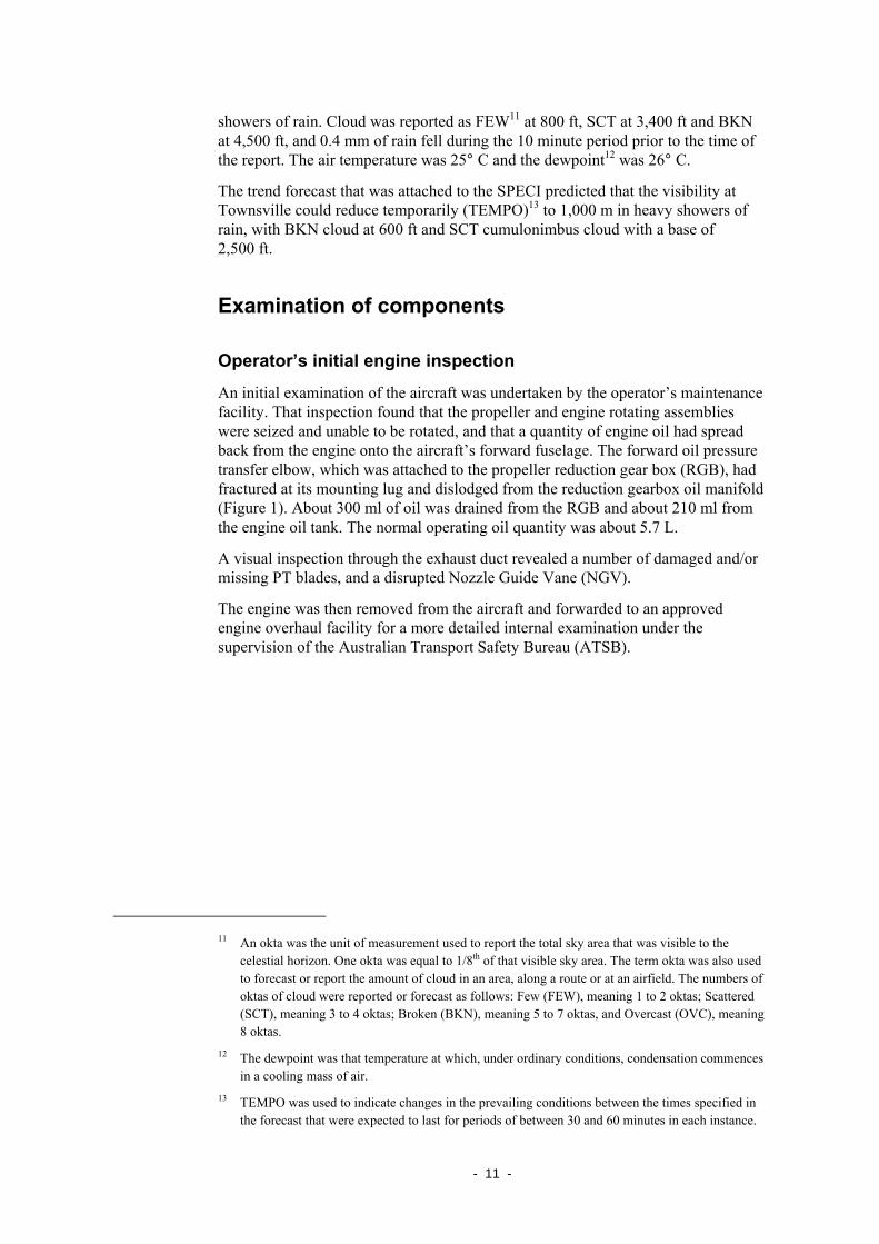
An initial examination of the aircraft was undertaken by the operator’s maintenance facility. That inspection found that the propeller and engine rotating assemblies were seized and unable to be rotated, and that a quantity of engine oil had spread back from the engine onto the aircraft’s forward fuselage. The forward oil pressure transfer elbow, which was attached to the propeller reduction gear box (RGB), had fractured at its mounting lug and dislodged from the reduction gearbox oil manifold (Figure 1). About 300 ml of oil was drained from the RGB and about 210 ml from the engine oil tank. The normal operating oil quantity was about 5.7 L.
A visual inspection through the exhaust duct revealed a number of damaged and/or missing PT blades, and a disrupted Nozzle Guide Vane (NGV).
The engine was then removed from the aircraft and forwarded to an approved engine overhaul facility for a more detailed internal examination under the supervision of the Australian Transport Safety Bureau (ATSB).
11 An okta was the unit of measurement used to report the total sky area that was visible to the
celestial horizon. One okta was equal to 1/8th of that visible sky area. The term okta was also used to forecast or report the amount of cloud in an area, along a route or at an airfield. The numbers of oktas of cloud were reported or forecast as follows: Few (FEW), meaning 1 to 2 oktas; Scattered (SCT), meaning 3 to 4 oktas; Broken (BKN), meaning 5 to 7 oktas, and Overcast (OVC), meaning 8 oktas.
12 The dewpoint was that temperature at which, under ordinary conditions, condensation commences in a cooling mass of air.
13 TEMPO was used to indicate changes in the prevailing conditions between the times specified in the forecast that were expected to last for periods of between 30 and 60 minutes in each instance.
- 12 -
Figure 1: Fractured mounting lug and RGB oil tube disconnect
Engine disassembly
The engine was unpacked at the approved engine overhaul facility and an external examination carried out under the supervision of the ATSB. The engine was then progressively disassembled.
A number of turbine blades were found to be broken from the CT and PT discs, and there was extensive damage to the turbine stators and interstage components. The engine’s nine CT shroud segments were intact and in position, having sustained extensive impact-related indentation damage around their circumference.The first stage axial compressor was visually inspected and found to be complete.
Engine lubrication was confirmed, with oil observed in the RGB and no bearing damage evident. A number of items, including the CT blades and disc, were retained for specialist metallurgical examination (refer Appendix A).
Technical examination of retained components
Compressor turbine disc and blades
All but one of the CT blades were fractured through the outermost half of the airfoil section span (Figure 2). The nature of the fracture of those blades was consistent with hard-object impacts during the rotation of the disc. The outer circumference of the disc and rear faces of the blade roots showed heavy rotational scoring.
Fractured mounting lug
Oil pressure to RGB disconnected
- 13 -
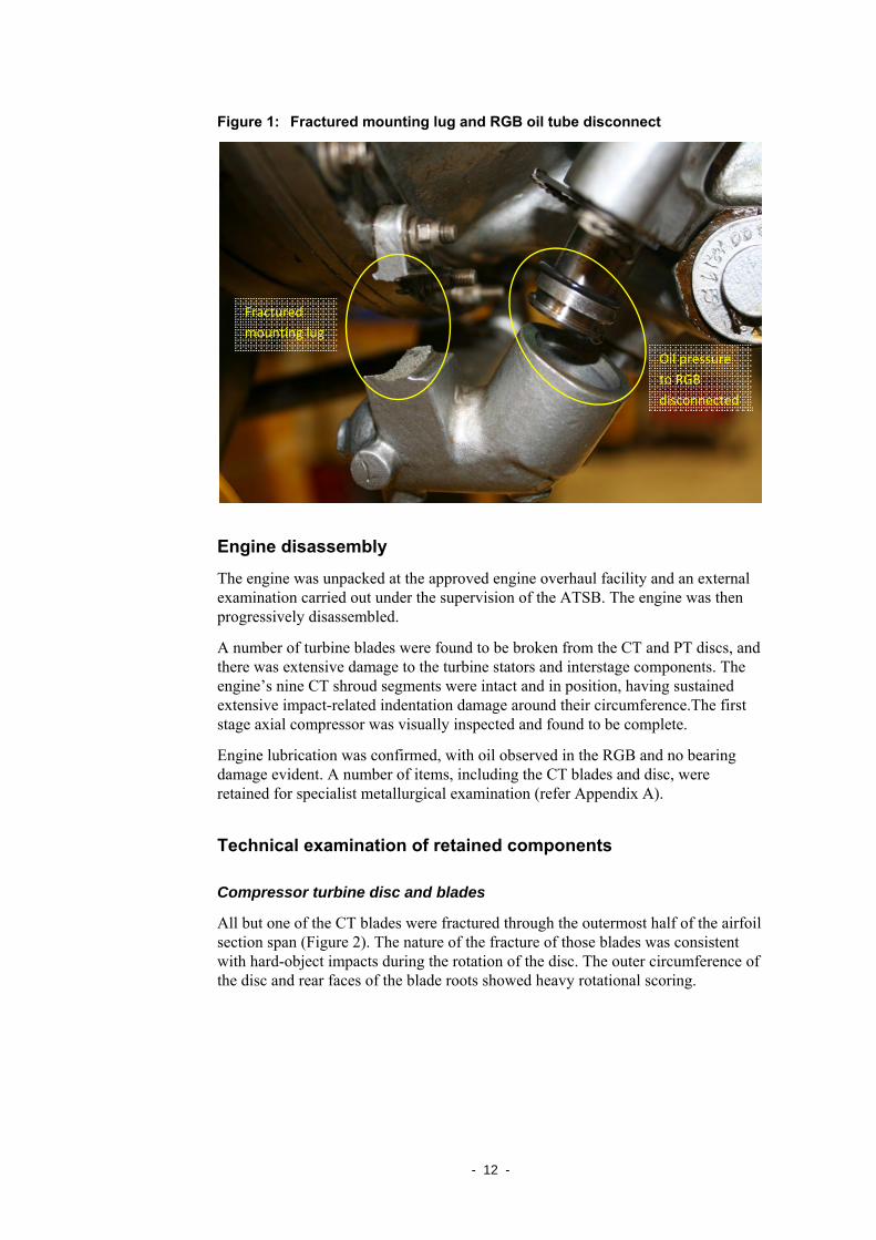
Figure 2: Missing and damaged CT blades and disc
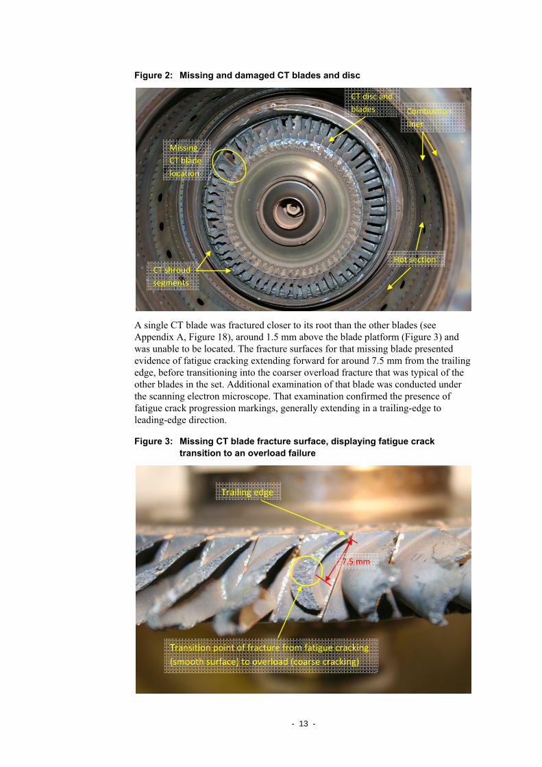
A single CT blade was fractured closer to its root than the other blades (see Appendix A, Figure 18), around 1.5 mm above the blade platform (Figure 3) and was unable to be located. The fracture surfaces for that missing blade presented evidence of fatigue cracking extending forward for around 7.5 mm from the trailing edge, before transitioning into the coarser overload fracture that was typical of the other blades in the set. Additional examination of that blade was conducted under the scanning electron microscope. That examination confirmed the presence of fatigue crack progression markings, generally extending in a trailing-edge to leading-edge direction.
Figure 3: Missing CT blade fracture surface, displaying fatigue crack transition to an overload failure
Trailing edge
Transition point of fracture from fatigue cracking (smooth surface) to overload (coarse cracking)
7.5 mm
Missing CT blade location
Combustion liner
CT shroud segments
Hot section
CT disc and blades
- 14 -
A metallographic examination of the missing blade’s fracture surface found no evidence of material defects across the planes examined.
The protective coating thickness and trailing edge dimensions of the failed/missing CT blade met the manufacturer’s specifications for the blade type and the respective chemical compositions were typical of the specified materials. The blade’s general metallurgical condition was considered typical of its TSN.
Power turbine disc and blades
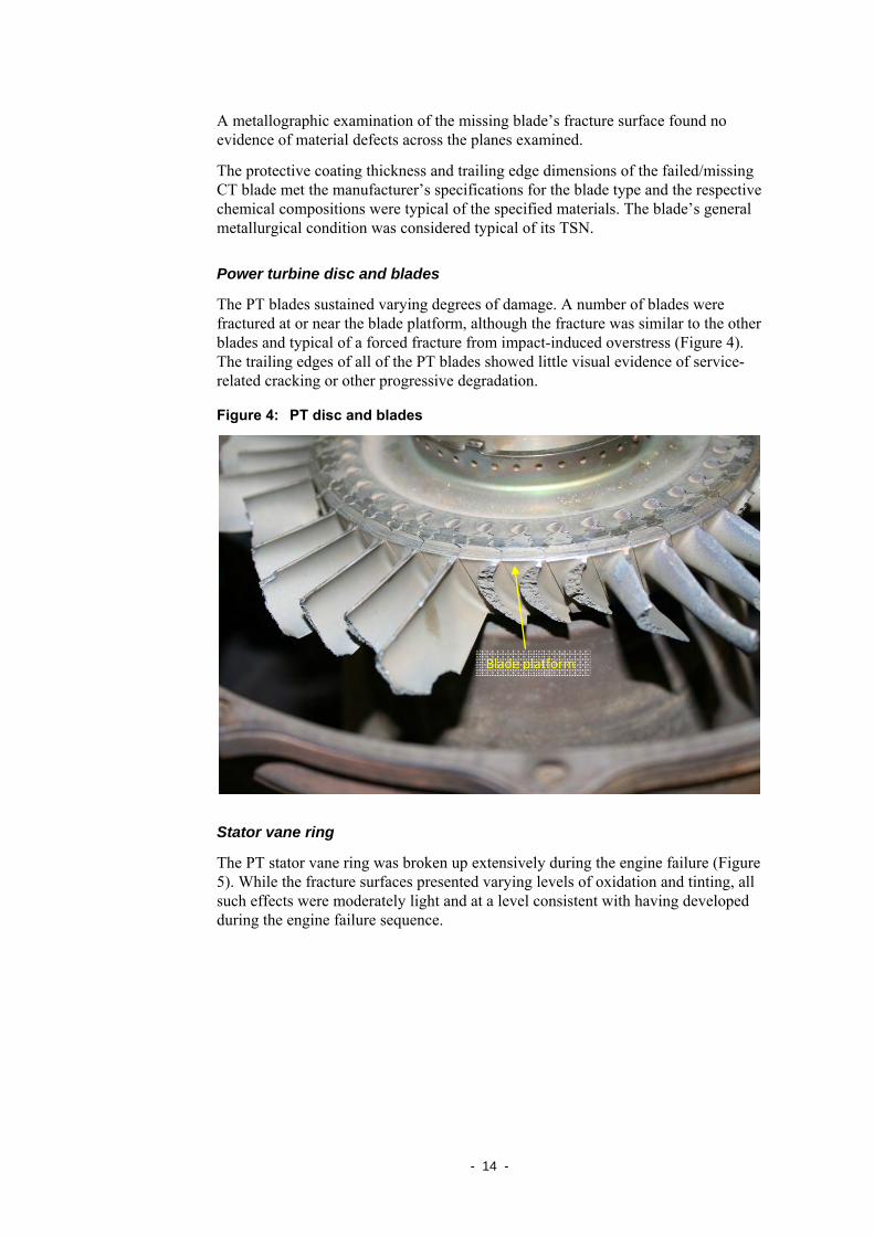
The PT blades sustained varying degrees of damage. A number of blades were fractured at or near the blade platform, although the fracture was similar to the other blades and typical of a forced fracture from impact-induced overstress (Figure 4). The trailing edges of all of the PT blades showed little visual evidence of service-related cracking or other progressive degradation.
Figure 4: PT disc and blades
Stator vane ring
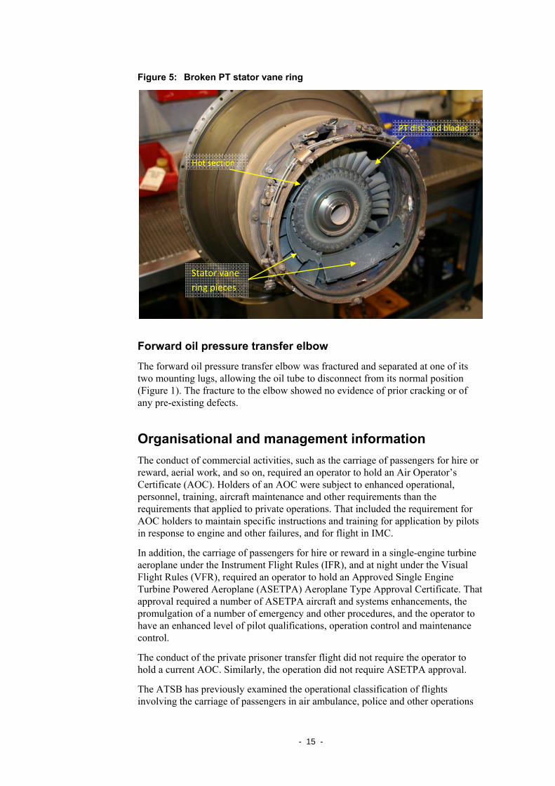
The PT stator vane ring was broken up extensively during the engine failure (Figure 5). While the fracture surfaces presented varying levels of oxidation and tinting, all such effects were moderately light and at a level consistent with having developed during the engine failure sequence.
Blade platform
- 15 -
Figure 5: Broken PT stator vane ring
Forward oil pressure transfer elbow
The forward oil pressure transfer elbow was fractured and separated at one of its two mounting lugs, allowing the oil tube to disconnect from its normal position (Figure 1). The fracture to the elbow showed no evidence of prior cracking or of any pre-existing defects.
Organisational and management information The conduct of commercial activities, such as the carriage of passengers for hire or reward, aerial work, and so on, required an operator to hold an Air Operator’s Certificate (AOC). Holders of an AOC were subject to enhanced operational, personnel, training, aircraft maintenance and other requirements than the requirements that applied to private operations. That included the requirement for AOC holders to maintain specific instructions and training for application by pilots in response to engine and other failures, and for flight in IMC.
In addition, the carriage of passengers for hire or reward in a single-engine turbine aeroplane under the Instrument Flight Rules (IFR), and at night under the Visual Flight Rules (VFR), required an operator to hold an Approved Single Engine Turbine Powered Aeroplane (ASETPA) Aeroplane Type Approval Certificate. That approval required a number of ASETPA aircraft and systems enhancements, the promulgation of a number of emergency and other procedures, and the operator to have an enhanced level of pilot qualifications, operation control and maintenance control.
The conduct of the private prisoner transfer flight did not require the operator to hold a current AOC. Similarly, the operation did not require ASETPA approval.
The ATSB has previously examined the operational classification of flights involving the carriage of passengers in air ambulance, police and other operations
Stator vane ring pieces
PT disc and blades
Hot section
- 16 -
(for example, see Air Safety Investigation 200100348 at www.atsb.gov.au). In addition, on 7 September 2001, the ATSB issued the following safety recommendation to the Civil Aviation Safety Authority (also available at www.atsb.gov.au):
Safety Recommendation R20010195
The Australian Transport Safety Bureau recommends that the Civil Aviation Safety Authority consider proposing an increase in the operations' classification, and/or the minimum safety standards required, for organisations that transport their own employees and similar personnel (for example contractors, personnel from related organisations, or prisoners, but not fare-paying passengers) on a regular basis. This recommendation applies to all such operations, regardless of the take-off weight of the aircraft involved.
On 21 December 2004, CASA advised that:
A Notice of Proposed Rule Making (NPRM) proposing amendments to Civil Aviation Regulation (CAR) 206 was issued in March 2003. Responses to this NPRM and the associated review of the Classification of Operations confirmed that the proposed amendment to CAR 206, which would accommodate this recommendation would be problematic. Consequently, CASA has decided [to] proceed only with the other amendments to CAR 206. The associated NFRM is currently with the Department of Transport and Regional Services for clearance prior to Ministerial approval.
However, under the new Civil Aviation Safety Regulations, Corporate Operations will be classified as Aerial work and will be regulated under CASR Part 132. The carriage of patients and other personnel (other than air transport operations) will be regarded as Aerial Work under a subpart of Part 136 to be titled Emergency and Medical Services Operations. It is proposed that 'Emergency Services Flights' will cover aerial fire-fighting, law enforcement, and search and rescue operations, while 'Medical Services Flights' will cover air ambulance flights, health services flights, and emergency medical services flights. The development of these regulations is proceeding in consultation with industry.
Based on that advice, and the understanding that Civil Aviation Safety Regulations (CASR) Parts 132 and 136 would, in part, address its safety recommendation, the ATSB reclassified the recommendation as ‘Closed – Partially Accepted’.
In 2006, CASA commenced a new Classification of Operations project that culminated in the issue of Regulatory Policy CEO-PN001-2004. The policy highlighted that CASA was moving towards a risk-based hierarchy of priorities, allocating its resources in regard to the degree of risk to members of the public. CASA advised that, in accordance with that policy, activities should be classified primarily on the basis of those carried on the flight. One of the three broad classes of aviation activities established under the policy, was Passenger Transport. Passenger Transport involved the:
...carriage of passengers, i.e. occupants who have limited or no knowledge of the risks to which they are exposed and little or no control over the risks.
- 17 -
ANALYSIS
Engine failure mechanism The evidence showed that the failure of the engine was precipitated by the fracture and separation of a single blade from the compressor turbine (CT) disc. The gross mechanical interference caused by the release of that blade into the confines of the turbine section contributed to the subsequent forced-fracture of the other CT blades and the downstream migration of blade debris. The remainder of the internal engine damage was identified as secondary damage as a result of that debris.
CT blade failure mechanism The CT blade fracture surface characteristics indicated the initiation of a high-cycle fatigue cracking mechanism that propagated from the blade’s trailing edge, along a chord-wise plane towards its leading edge. That mechanism originated from a low stress and high repetition environment. The abrupt transition to ductile fracture morphology was evidence of the final overstress separation of the blade, at a fatigue crack length of approximately 7.5 mm.
The consistency of the CT blade’s condition with its time accrued since new provided some assurance that it had not sustained any significant degree of overheating during service.
Due to the extent of the post separation mechanical damage and the degree of surface oxidation at the fatigue crack origin, it was not possible to identify the initiating cause. However, it was likely that the level of surface oxidation and mechanical damage sustained in the region of the fatigue crack origin degraded or destroyed any evidence that may have supported a conclusion in that respect. Fundamentally however, in view of the absence of any significant material deficiencies, the initiation of fatigue cracking from the blade trailing edge would have required the pre-existence of a physical stress-concentration at the point of origin. Such a feature could have arisen from the effects of the previous passage of foreign object damage (FOD) through the engine, from handling or tooling damage sustained during a prior maintenance activity, or from the effects of an isolated blade casting anomaly that was not evident to the examination.
Forward oil pressure transfer elbow The evidence showed that the fractured oil pressure transfer elbow attachment lug was the result of excessive vibration caused by the internal failure of the engine. Although some oil was pumped overboard, a sufficient quantity of oil remained in the engine to lubricate and prevent seizure of the bearings and components until the propeller was feathered, and the fuel supply to the engine was cut off by the pilot.
Classification of operations The conduct of the prisoner transfer as a private flight meant that a number of risk controls that applied in the case of the carriage of passengers for hire or reward

- 18 -
were not afforded to the prisoner transfer passengers. In particular, the lack of guidance in response to an engine failure, or to the need to turn back in Instrument Meteorological Conditions (IMC), emphasised the benefit for the pilot of the engine failure occurring in close proximity to Townsville Airport.
It appears that Civil Aviation Safety Regulation (CASR) Part 136 will, when published, recategorise law enforcement operations as aerial work. It could be expected that would result in changes to the operational, personnel, training, aircraft maintenance and other requirements affecting those operations.
19
FINDINGS From the evidence available, the following findings are made with respect to the engine failure involving Cessna 208, registration VH-PSQ, on 14 January 2008 and should not be read as apportioning blame or liability to any particular organisation or individual.
Contributing safety factors • The engine failure was consistent with the mechanical disruption and breakage
of componentry within the turbine (hot) section of the engine.
• The fracture and liberation of a single blade from the compressor turbine wheel initiated the damage to the turbine section.
• The fracture of the compressor turbine blade resulted from the initiation of a high-cycle fatigue crack from the blade trailing edge, and the subsequent growth of that crack through the lower aerofoil section.
Other safety factors • The engine failed while the aircraft was climbing in Instrument Meteorological
Conditions (IMC).
Other key findings • The engine compressor turbine blades were verified as the appropriate part-
number and construction for the engine model and configuration.
• There was no evidence of gross manufacturing deficiencies within the blade microstructure at, and adjacent to, the location of crack initiation.
• There were no signs of significant overheating of the failed compressor turbine blade during its service life.
• The factor(s) that directly contributed to the initiation of the fatigue cracking could not be determined during the course of the investigation.

– 20 –
– 21 –
SAFETY ACTION The safety issues identified during this investigation are listed in the Findings and Safety Actions sections of this report. The Australian Transport Safety Bureau (ATSB) expects that all safety issues identified by the investigation should be addressed by the relevant organisation(s). In addressing those issues, the ATSB prefers to encourage relevant organisation(s) to proactively initiate safety action, rather than to issue formal safety recommendations or safety advisory notices.
All of the responsible organisations for the safety issues identified during this investigation were given a draft report and invited to provide submissions. As part of that process, each organisation was asked to communicate what safety actions, if any, they had carried out or were planning to carry out in relation to each safety issue relevant to their organisation.
Aircraft operator
Pilot situational awareness
Action taken by the aircraft operator
Although not identified as a safety issue, following this incident, the operator reviewed the operating standards within the organisation. That review focussed on the:
• use by pilots of the available onboard equipment to maintain situational awareness when dealing with various engine failure situations, particularly when in instrument meteorological conditions (IMC)
• appropriate decision-making processes to terminate the flight safely.
In addition, the operator indicated that its operating procedures were examined with a view to enhancing pilot situational awareness. That resulted in the operator:
• raising the prescribed take-off minima (ceiling and visibility) on the basis of the surrounding terrain, and in respect of an escape route should the aircraft’s engine fail after takeoff
• requiring the aircraft’s enhanced ground proximity warning system (EGPWS) to be set to ‘Terrain Mode’ when operating below the planned cruise level
• requiring the EGPWS to be ranged down to 5 or 10 NM, or as dictated by the aircraft’s glide distance, during an engine failure, in order to reduce information overload
• if an engine failure occurred in IMC, requiring the use the EGPWS as a primary reference for terrain avoidance during the emergency descent until pilots gained visual reference
• programming all available user-authorised landing areas into the aircraft’s global positioning system (GPS) equipment to maximise the ‘Nearest-to’ options
• stipulating flight planning over routes that improved alternate options

– 22 –
• developing a number of procedures for application in the case of an engine failure during an instrument approach.
– 23 –
APPENDIX A: TECHNICAL ANALYSIS REPORT
ATSB TECHNICAL ANALYSIS AO-2008-005
Engineering Failure Analysis of Turboprop Engine Components
Pratt & Whitney Canada, PT6A-114
Cessna Aircraft Co. 208 Caravan VH-PSQ, 14 January 2008
Released in accordance with section 25 of the Transport Safety Investigation Act 2003
– 24 –
SUMMARY On 14 January 2008, shortly after takeoff from Townsville aerodrome, Qld, a Cessna Aircraft Co. C208 Caravan aircraft (VH-PSQ) sustained a substantial mechanical failure within its single PT6A-114 turboprop engine, producing a complete loss of power and necessitating an immediate forced landing. Following disassembly and inspection of the engine, components of the turbine section were examined in detail by the Australian Transport Safety Bureau. From that examination, it was evident that the engine breakdown had been precipitated by the fatigue cracking and subsequent separation of a single blade from the compressor turbine wheel. Blade fatigue cracking had originated from the lower aerofoil trailing edge and propagated chord-wise until an overstress rupture released the segment into the engine confines, producing the subsequent substantial levels of downstream damage. Metallurgical study of the remaining blade section confirmed, as far as possible, the general compliance of the component with the manufacturer’s specified blade materials and trailing edge dimensions. Damage to the area of crack initiation limited the extent of examination such that the root cause of fatigue initiation could not be established with certainty. However, from the available evidence, it was considered likely that the crack initiated at a localised area of stress concentration, such as may have arisen from the passage of foreign object debris through the engine, from handling or tooling damage sustained during a prior maintenance activity, or from the effects of an isolated blade casting anomaly that was not evident to the examination.
.
– 25 –
FACTUAL INFORMATION
Introduction
On 14 January 2008, shortly after departing from Townsville aerodrome, Qld, and while climbing through an altitude of around 5,000 ft, the pilot of a Cessna Aircraft Co. 208 Caravan, registered VH-PSQ, reported to air traffic control that the engine had failed and that he was endeavouring to return to the aerodrome. The subsequent un-powered approach and landing was successful and the aircraft was undamaged.
The pilot reported that the engine failure had initially manifested as a slight vibration, lasting for around 4 seconds, followed by a progressive drop in output power over approximately 10 seconds. On advancing the emergency fuel lever14, the pilot reported hearing a loud ‘squeal and grinding noise’. After attempts to re-start the engine failed and smoke was noticed coming from the exhausts, the pilot secured the engine by feathering the propeller and selecting the fuel cut-off.
The Cessna 208 aircraft (serial number 20800213) was manufactured in 1992. The aircraft was fitted with a single Pratt & Whitney Canada (PWC) PT6A-114 turboprop engine, driving a McCauley model 3GFR34C703 constant-speed and reversible propeller.
Preliminary examination
Following removal from the aircraft, the engine (serial number PCE-17458) underwent a progressive disassembly and examination under the supervision of Australian Transport Safety Bureau (ATSB) investigators. During that examination, damage was identified within the turbine (hot-section) of the engine, including the breakage of blades from both compressor and power turbine discs and extensive damage to the turbine stators and interstage components. Externally, the only visible damage was a fractured lug on an oil feed tube feeding the reduction gearbox (RGB) on the right side of the engine.
All principle turbine and compressor shaft bearings were reported as being intact and showed no evidence of distress, overheating or collapse.
14 The emergency power lever is a device fitted to allow fuel flow to be maintained to the engine in
the event of a failure within the fuel control unit (FCU). It mechanically overrides the FCU linkages.
– 26 –
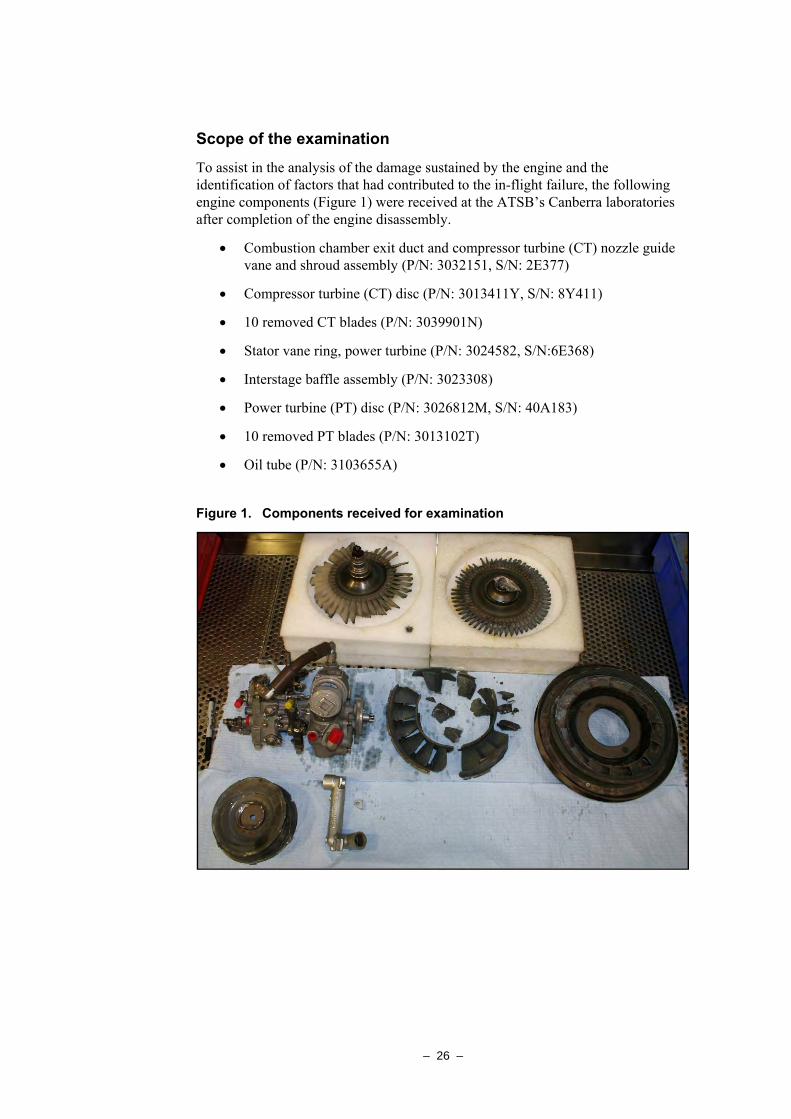
Scope of the examination
To assist in the analysis of the damage sustained by the engine and the identification of factors that had contributed to the in-flight failure, the following engine components (Figure 1) were received at the ATSB’s Canberra laboratories after completion of the engine disassembly.
• Combustion chamber exit duct and compressor turbine (CT) nozzle guide vane and shroud assembly (P/N: 3032151, S/N: 2E377)
• Compressor turbine (CT) disc (P/N: 3013411Y, S/N: 8Y411)
• 10 removed CT blades (P/N: 3039901N)
• Stator vane ring, power turbine (P/N: 3024582, S/N:6E368)
• Interstage baffle assembly (P/N: 3023308)
• Power turbine (PT) disc (P/N: 3026812M, S/N: 40A183)
• 10 removed PT blades (P/N: 3013102T)
• Oil tube (P/N: 3103655A)
Figure 1. Components received for examination
– 27 –
Engine details
The PWC PT6A-114 engine was a light-weight, free-turbine turboprop engine, employing a four-stage combined axial/centrifugal compressor with a single-stage axial compressor turbine and an independent single-stage axial power turbine driving the propeller via a reduction gearbox. The engine was rated at 477 kW / 600 shp.
At the time of the failure, the engine had accrued 9,041 hours since new (TSN) and 2,007 hours since the last overhaul (TSO) in November 2003. Records showed that all engine CT blades and shroud segments were replaced with new components during that overhaul.
The last engine hot-section inspection (HSI15) was completed in July 2007, at 8,826 hours TSN. The engine failure occurred 215 hours after the HSI. Maintenance activity carried out on the engine during the HSI included a repair to the combustion liner, a compressor turbine segment grind, and stop-drilling16 of cracks within the combustion chamber exit ducts.
Component examination
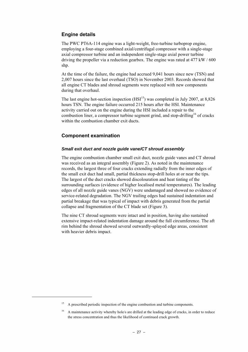
Small exit duct and nozzle guide vane/CT shroud assembly
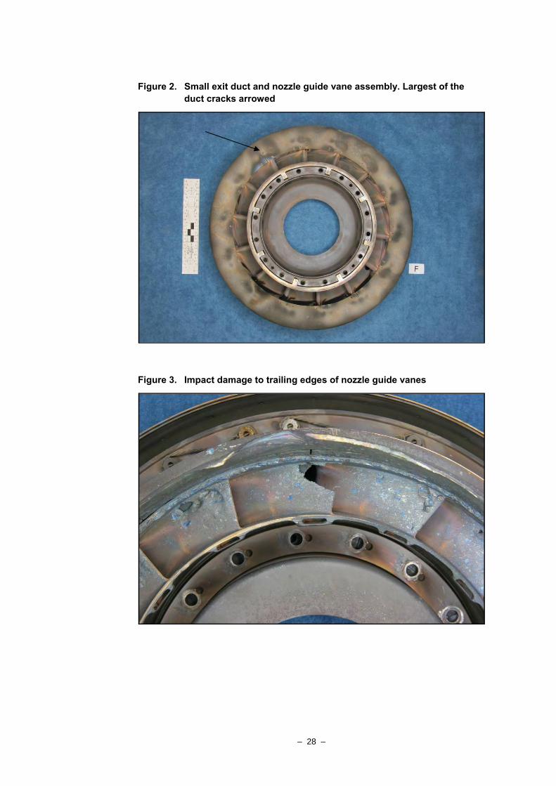
The engine combustion chamber small exit duct, nozzle guide vanes and CT shroud was received as an integral assembly (Figure 2). As noted in the maintenance records, the largest three of four cracks extending radially from the inner edges of the small exit duct had small, partial thickness stop-drill holes at or near the tips. The largest of the duct cracks showed discolouration and heat tinting of the surrounding surfaces (evidence of higher localised metal temperatures). The leading edges of all nozzle guide vanes (NGV) were undamaged and showed no evidence of service-related degradation. The NGV trailing edges had sustained indentation and partial breakage that was typical of impact with debris generated from the partial collapse and fragmentation of the CT blade set (Figure 3).
The nine CT shroud segments were intact and in position, having also sustained extensive impact-related indentation damage around the full circumference. The aft rim behind the shroud showed several outwardly-splayed edge areas, consistent with heavier debris impact.
15 A prescribed periodic inspection of the engine combustion and turbine components. 16 A maintenance activity whereby hole/s are drilled at the leading edge of cracks, in order to reduce
the stress concentration and thus the likelihood of continued crack growth.
– 28 –
Figure 2. Small exit duct and nozzle guide vane assembly. Largest of the duct cracks arrowed
Figure 3. Impact damage to trailing edges of nozzle guide vanes
– 29 –
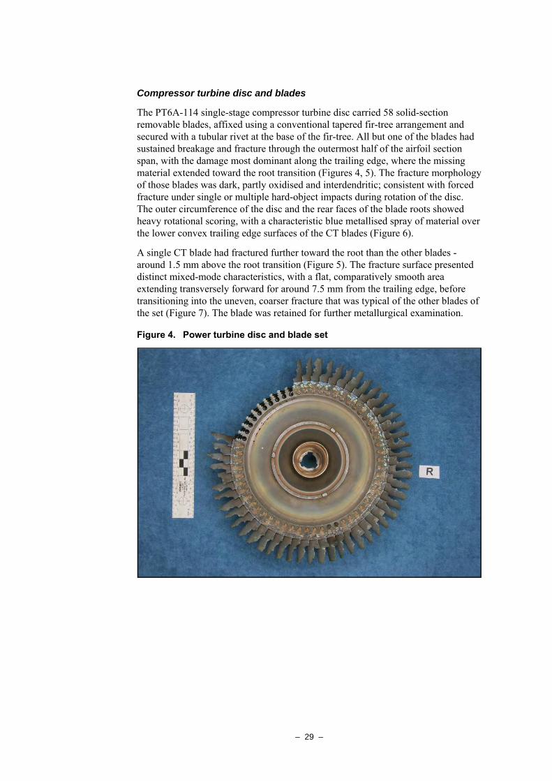
Compressor turbine disc and blades
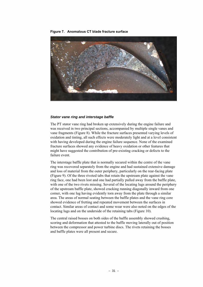
The PT6A-114 single-stage compressor turbine disc carried 58 solid-section removable blades, affixed using a conventional tapered fir-tree arrangement and secured with a tubular rivet at the base of the fir-tree. All but one of the blades had sustained breakage and fracture through the outermost half of the airfoil section span, with the damage most dominant along the trailing edge, where the missing material extended toward the root transition (Figures 4, 5). The fracture morphology of those blades was dark, partly oxidised and interdendritic; consistent with forced fracture under single or multiple hard-object impacts during rotation of the disc. The outer circumference of the disc and the rear faces of the blade roots showed heavy rotational scoring, with a characteristic blue metallised spray of material over the lower convex trailing edge surfaces of the CT blades (Figure 6).
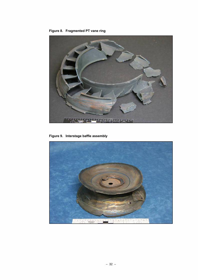
A single CT blade had fractured further toward the root than the other blades - around 1.5 mm above the root transition (Figure 5). The fracture surface presented distinct mixed-mode characteristics, with a flat, comparatively smooth area extending transversely forward for around 7.5 mm from the trailing edge, before transitioning into the uneven, coarser fracture that was typical of the other blades of the set (Figure 7). The blade was retained for further metallurgical examination.
Figure 4. Power turbine disc and blade set
– 30 –
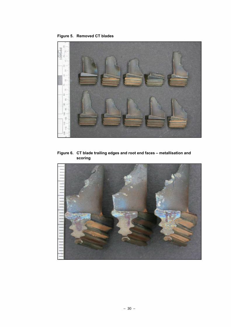
Figure 5. Removed CT blades
Figure 6. CT blade trailing edges and root end faces – metallisation and scoring
– 31 –
Figure 7. Anomalous CT blade fracture surface
Stator vane ring and interstage baffle
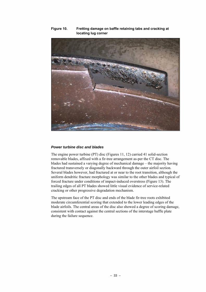
The PT stator vane ring had broken up extensively during the engine failure and was received in two principal sections, accompanied by multiple single vanes and vane fragments (Figure 8). While the fracture surfaces presented varying levels of oxidation and tinting, all such effects were moderately light and at a level consistent with having developed during the engine failure sequence. None of the examined fracture surfaces showed any evidence of heavy oxidation or other features that might have suggested the contribution of pre-existing cracking or defects to the failure event.
The interstage baffle plate that is normally secured within the centre of the vane ring was recovered separately from the engine and had sustained extensive damage and loss of material from the outer periphery, particularly on the rear-facing plate (Figure 9). Of the three riveted tabs that retain the upstream plate against the vane ring face, one had been lost and one had partially pulled away from the baffle plate, with one of the two rivets missing. Several of the locating lugs around the periphery of the upstream baffle plate, showed cracking running diagonally inward from one corner, with one lug having evidently torn away from the plate through a similar area. The areas of normal seating between the baffle plates and the vane ring core showed evidence of fretting and repeated movement between the surfaces in contact. Similar areas of contact and some wear were also noted on the edges of the locating lugs and on the underside of the retaining tabs (Figure 10).
The central raised bosses on both sides of the baffle assembly showed crushing, scoring and deformation that attested to the baffle moving laterally out of position between the compressor and power turbine discs. The rivets retaining the bosses and baffle plates were all present and secure.
– 32 –
Figure 8. Fragmented PT vane ring
Figure 9. Interstage baffle assembly
– 33 –
Figure 10. Fretting damage on baffle retaining tabs and cracking at locating lug corner
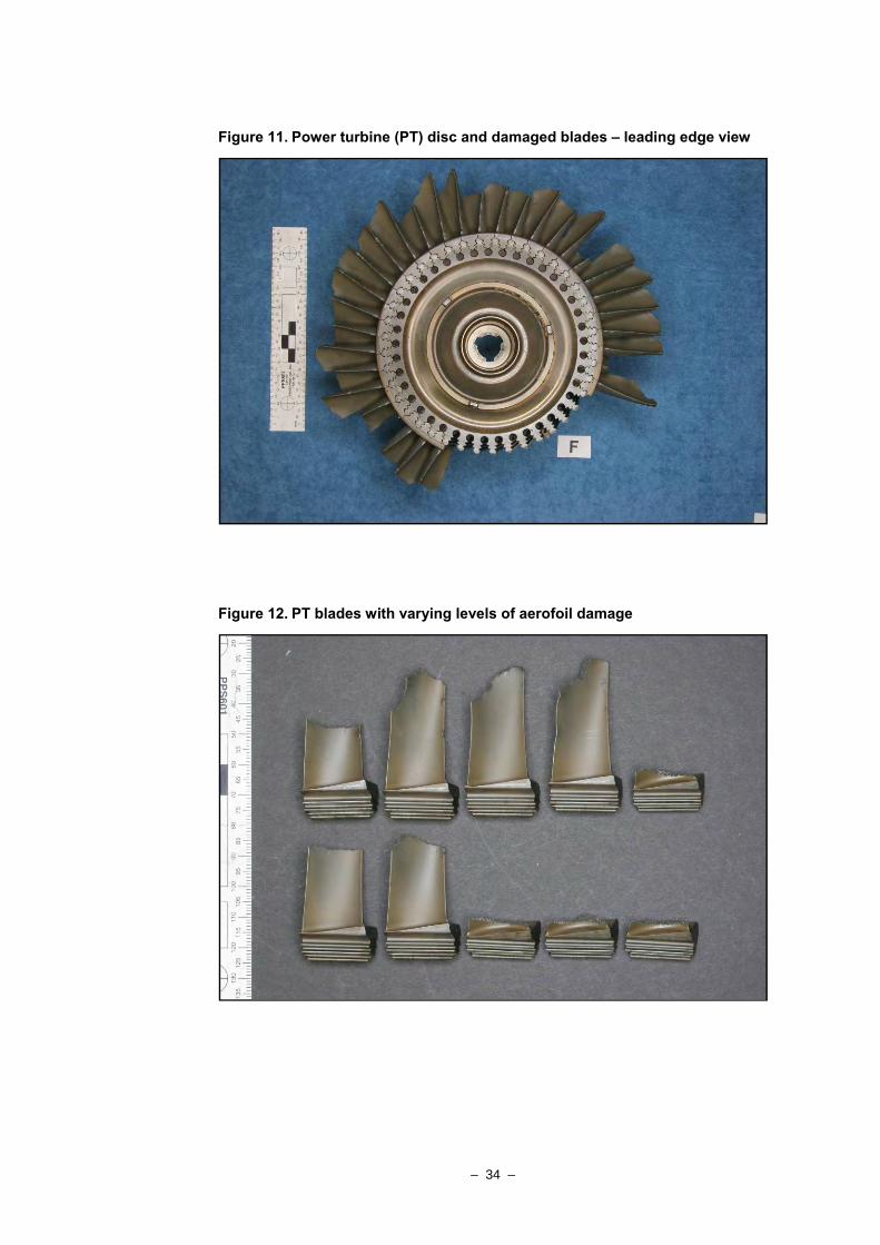
Power turbine disc and blades
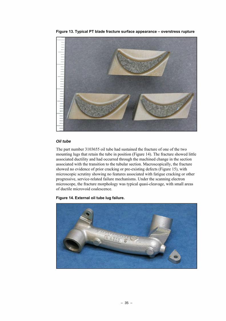
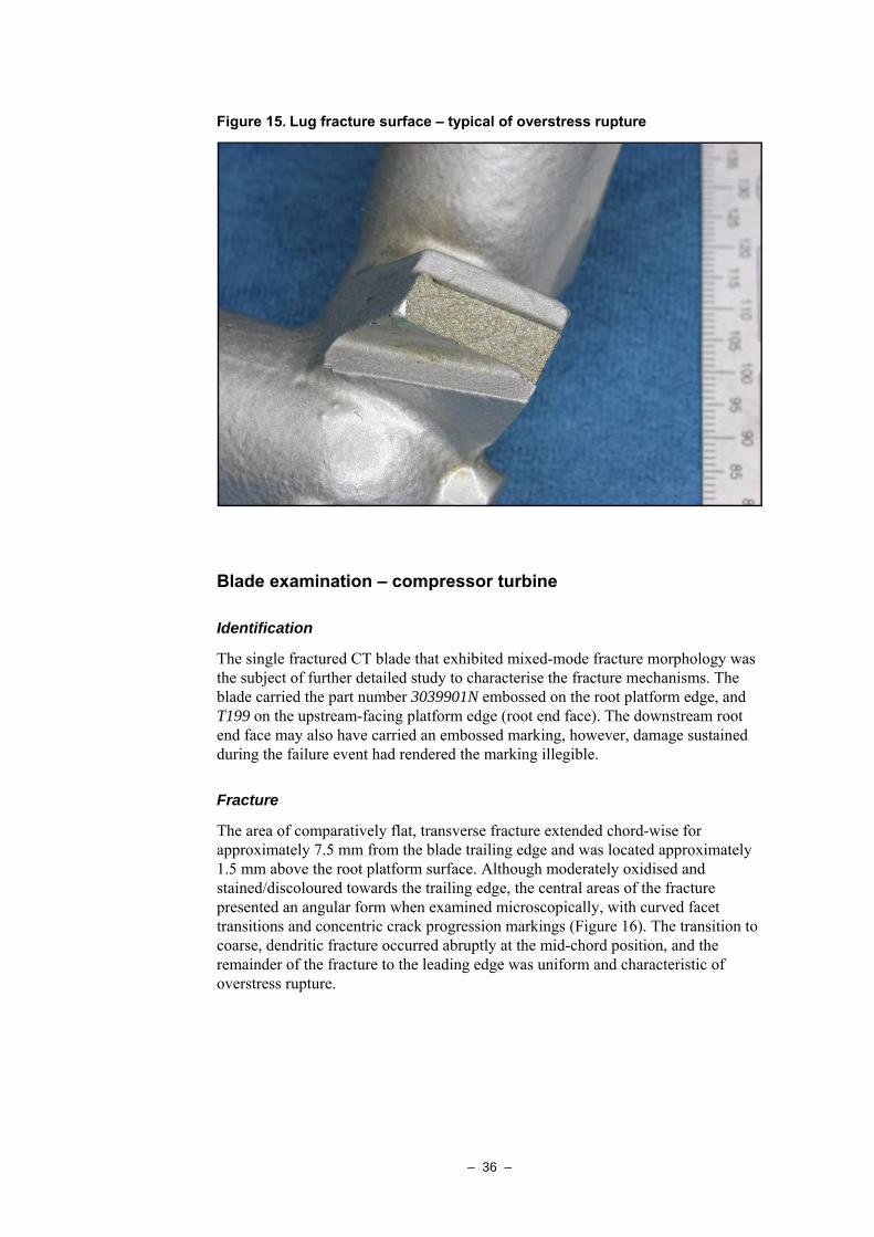
The engine power turbine (PT) disc (Figures 11, 12) carried 41 solid-section removable blades, affixed with a fir-tree arrangement as-per the CT disc. The blades had sustained a varying degree of mechanical damage – the majority having fractured transversely or diagonally backward through the outer airfoil section. Several blades however, had fractured at or near to the root transition, although the uniform dendritic fracture morphology was similar to the other blades and typical of forced fracture under conditions of impact-induced overstress (Figure 13). The trailing edges of all PT blades showed little visual evidence of service-related cracking or other progressive degradation mechanism.
The upstream face of the PT disc and ends of the blade fir-tree roots exhibited moderate circumferential scoring that extended to the lower leading edges of the blade airfoils. The central areas of the disc also showed a degree of scoring damage, consistent with contact against the central sections of the interstage baffle plate during the failure sequence.
– 34 –
Figure 11. Power turbine (PT) disc and damaged blades – leading edge view
Figure 12. PT blades with varying levels of aerofoil damage
– 35 –
Figure 13. Typical PT blade fracture surface appearance – overstress rupture
Oil tube
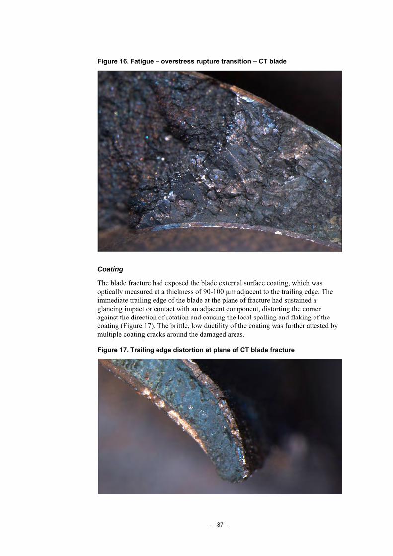
The part number 3103655 oil tube had sustained the fracture of one of the two mounting lugs that retain the tube in position (Figure 14). The fracture showed little associated ductility and had occurred through the machined change in the section associated with the transition to the tubular section. Macroscopically, the fracture showed no evidence of prior cracking or pre-existing defects (Figure 15), with microscopic scrutiny showing no features associated with fatigue cracking or other progressive, service-related failure mechanisms. Under the scanning electron microscope, the fracture morphology was typical quasi-cleavage, with small areas of ductile microvoid coalescence.
Figure 14. External oil tube lug failure.
– 36 –
Figure 15. Lug fracture surface – typical of overstress rupture
Blade examination – compressor turbine
Identification
The single fractured CT blade that exhibited mixed-mode fracture morphology was the subject of further detailed study to characterise the fracture mechanisms. The blade carried the part number 3039901N embossed on the root platform edge, and T199 on the upstream-facing platform edge (root end face). The downstream root end face may also have carried an embossed marking, however, damage sustained during the failure event had rendered the marking illegible.
Fracture
The area of comparatively flat, transverse fracture extended chord-wise for approximately 7.5 mm from the blade trailing edge and was located approximately 1.5 mm above the root platform surface. Although moderately oxidised and stained/discoloured towards the trailing edge, the central areas of the fracture presented an angular form when examined microscopically, with curved facet transitions and concentric crack progression markings (Figure 16). The transition to coarse, dendritic fracture occurred abruptly at the mid-chord position, and the remainder of the fracture to the leading edge was uniform and characteristic of overstress rupture.
– 37 –
Figure 16. Fatigue – overstress rupture transition – CT blade
Coating
The blade fracture had exposed the blade external surface coating, which was optically measured at a thickness of 90-100 µm adjacent to the trailing edge. The immediate trailing edge of the blade at the plane of fracture had sustained a glancing impact or contact with an adjacent component, distorting the corner against the direction of rotation and causing the local spalling and flaking of the coating (Figure 17). The brittle, low ductility of the coating was further attested by multiple coating cracks around the damaged areas.
Figure 17. Trailing edge distortion at plane of CT blade fracture
– 38 –
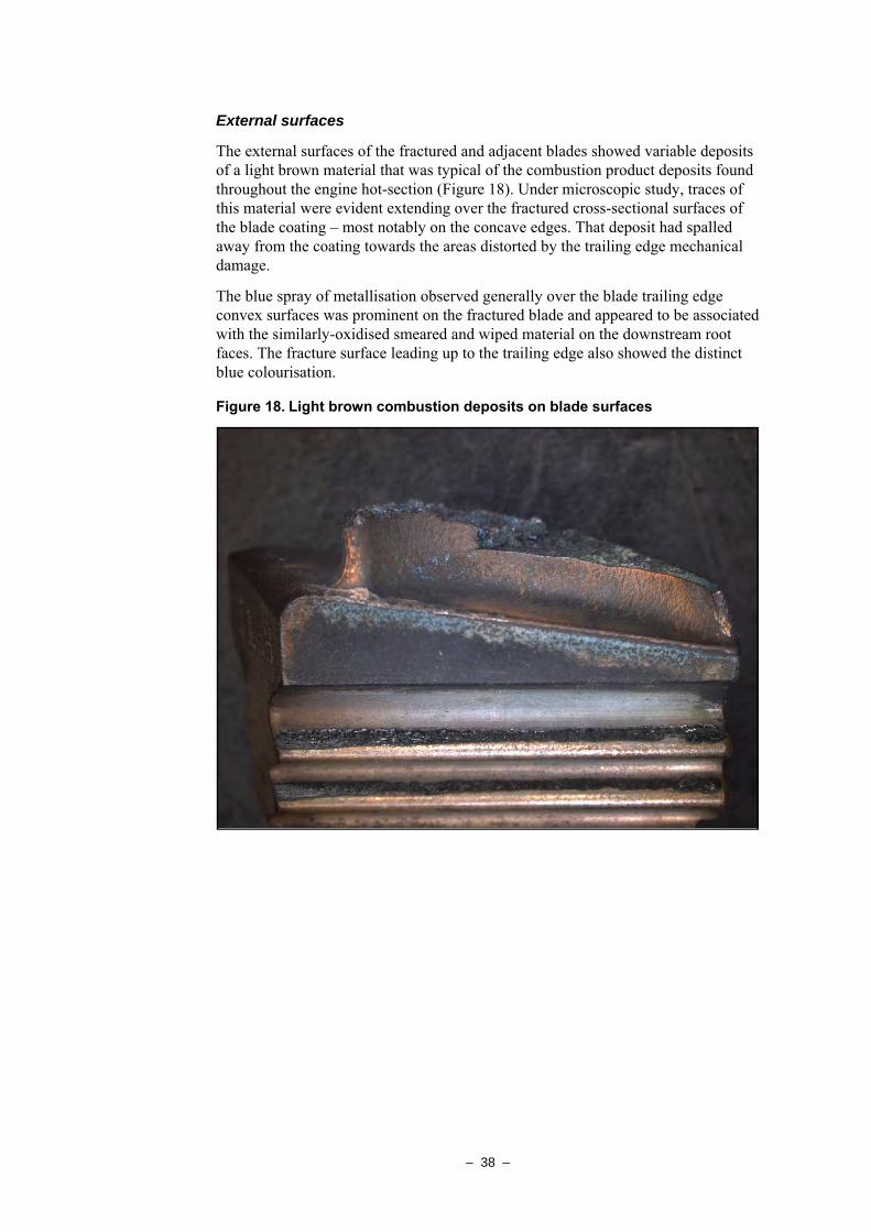
External surfaces
The external surfaces of the fractured and adjacent blades showed variable deposits of a light brown material that was typical of the combustion product deposits found throughout the engine hot-section (Figure 18). Under microscopic study, traces of this material were evident extending over the fractured cross-sectional surfaces of the blade coating – most notably on the concave edges. That deposit had spalled away from the coating towards the areas distorted by the trailing edge mechanical damage.
The blue spray of metallisation observed generally over the blade trailing edge convex surfaces was prominent on the fractured blade and appeared to be associated with the similarly-oxidised smeared and wiped material on the downstream root faces. The fracture surface leading up to the trailing edge also showed the distinct blue colourisation.
Figure 18. Light brown combustion deposits on blade surfaces
– 39 –
Electron microscopy and micro-analysis
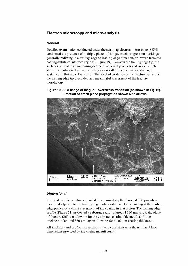
General
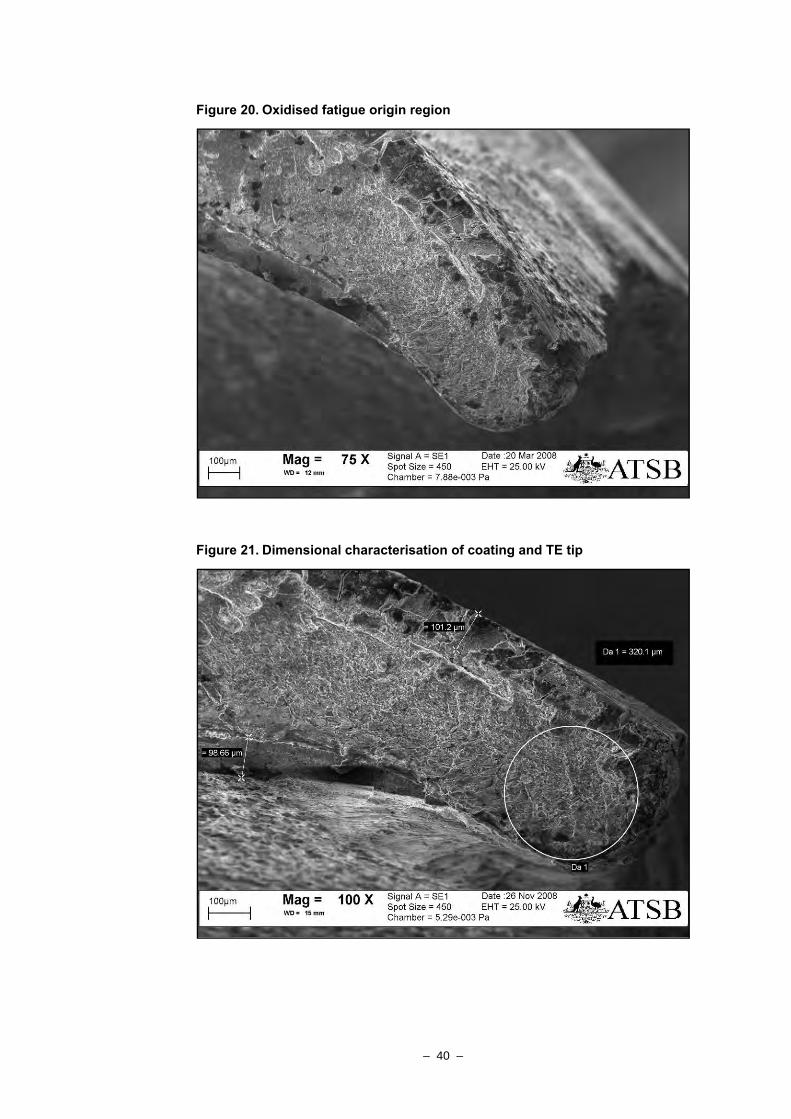
Detailed examination conducted under the scanning electron microscope (SEM) confirmed the presence of multiple planes of fatigue crack progression markings, generally radiating in a trailing-edge to leading-edge direction, or inward from the coating-substrate interface regions (Figure 19). Towards the trailing edge tip, the surfaces presented an increasing degree of adherent products and oxide, which showed angular cracking and spalling as a result of the mechanical damage sustained in that area (Figure 20). The level of oxidation of the fracture surface at the trailing edge tip precluded any meaningful assessment of the fracture morphology.
Figure 19. SEM image of fatigue – overstress transition (as shown in Fig 16). Direction of crack plane propagation shown with arrows
Dimensional
The blade surface coating extended to a nominal depth of around 100 µm when measured adjacent to the trailing edge radius – damage to the coating at the trailing edge prevented a direct assessment of the coating in that region. The trailing edge profile (Figure 21) presented a substrate radius of around 160 µm across the plane of fracture (260 µm allowing for the estimated coating thickness), and a tip thickness of around 520 µm (again allowing for a 100 µm coating thickness).
All thickness and profile measurements were consistent with the nominal blade dimensions provided by the engine manufacturer.
– 40 –
Figure 20. Oxidised fatigue origin region
Figure 21. Dimensional characterisation of coating and TE tip
– 41 –
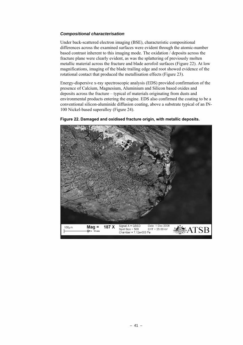
Compositional characterisation
Under back-scattered electron imaging (BSE), characteristic compositional differences across the examined surfaces were evident through the atomic-number based contrast inherent to this imaging mode. The oxidation / deposits across the fracture plane were clearly evident, as was the splattering of previously molten metallic material across the fracture and blade aerofoil surfaces (Figure 22). At low magnifications, imaging of the blade trailing edge and root showed evidence of the rotational contact that produced the metallisation effects (Figure 23).
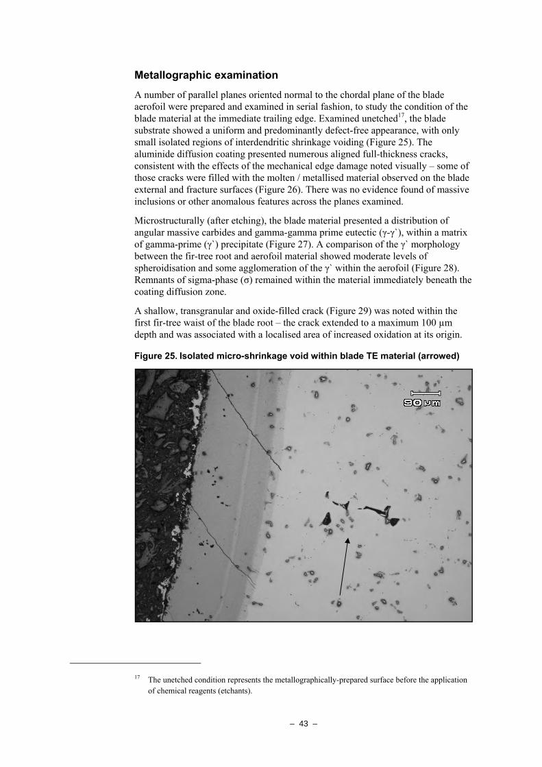
Energy-dispersive x-ray spectroscopic analysis (EDS) provided confirmation of the presence of Calcium, Magnesium, Aluminium and Silicon based oxides and deposits across the fracture – typical of materials originating from dusts and environmental products entering the engine. EDS also confirmed the coating to be a conventional silicon-aluminide diffusion coating, above a substrate typical of an IN-100 Nickel-based superalloy (Figure 24).
Figure 22. Damaged and oxidised fracture origin, with metallic deposits.
– 42 –
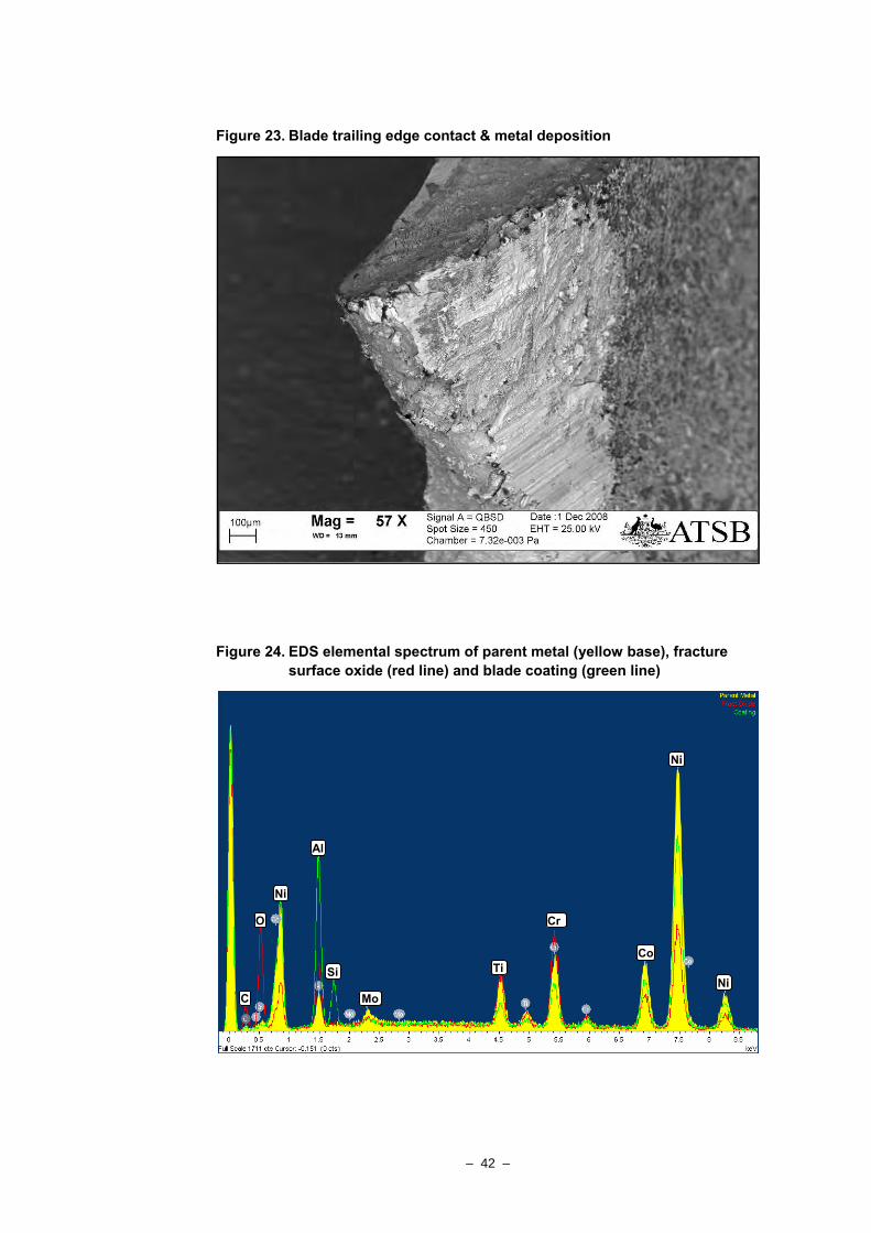
Figure 23. Blade trailing edge contact & metal deposition
Figure 24. EDS elemental spectrum of parent metal (yellow base), fracture surface oxide (red line) and blade coating (green line)
C
O
Ni
Al
Si
Mo
Ti
Cr
Ni
Co
Ni
– 43 –
Metallographic examination
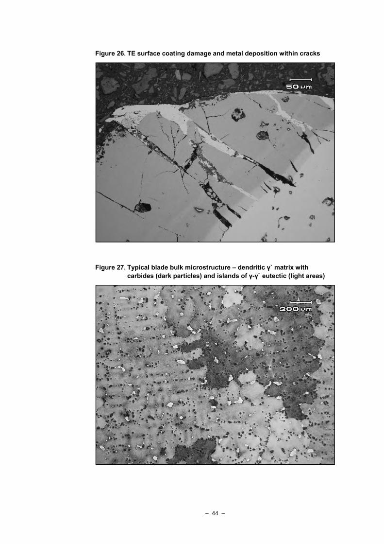
A number of parallel planes oriented normal to the chordal plane of the blade aerofoil were prepared and examined in serial fashion, to study the condition of the blade material at the immediate trailing edge. Examined unetched17, the blade substrate showed a uniform and predominantly defect-free appearance, with only small isolated regions of interdendritic shrinkage voiding (Figure 25). The aluminide diffusion coating presented numerous aligned full-thickness cracks, consistent with the effects of the mechanical edge damage noted visually – some of those cracks were filled with the molten / metallised material observed on the blade external and fracture surfaces (Figure 26). There was no evidence found of massive inclusions or other anomalous features across the planes examined.
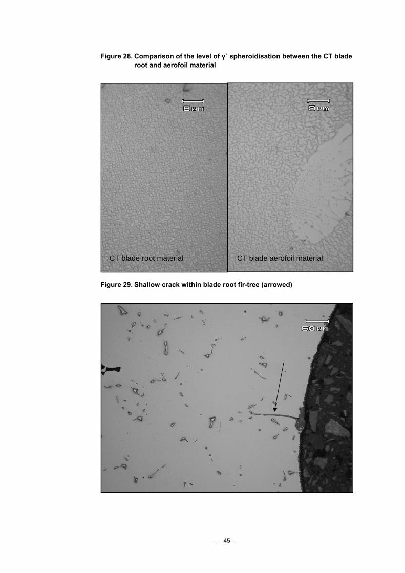
Microstructurally (after etching), the blade material presented a distribution of angular massive carbides and gamma-gamma prime eutectic (γ-γ`), within a matrix of gamma-prime (γ`) precipitate (Figure 27). A comparison of the γ` morphology between the fir-tree root and aerofoil material showed moderate levels of spheroidisation and some agglomeration of the γ` within the aerofoil (Figure 28). Remnants of sigma-phase (σ) remained within the material immediately beneath the coating diffusion zone.
A shallow, transgranular and oxide-filled crack (Figure 29) was noted within the first fir-tree waist of the blade root – the crack extended to a maximum 100 µm depth and was associated with a localised area of increased oxidation at its origin.
Figure 25. Isolated micro-shrinkage void within blade TE material (arrowed)
17 The unetched condition represents the metallographically-prepared surface before the application
of chemical reagents (etchants).
– 44 –
Figure 26. TE surface coating damage and metal deposition within cracks
Figure 27. Typical blade bulk microstructure – dendritic γ` matrix with carbides (dark particles) and islands of γ-γ` eutectic (light areas)
– 45 –
Figure 28. Comparison of the level of γ` spheroidisation between the CT blade root and aerofoil material
Figure 29. Shallow crack within blade root fir-tree (arrowed)
CT blade root material CT blade aerofoil material
– 46 –
ANALYSIS
Engine failure mechanism
From the observations made during the engine disassembly and subsequent laboratory examination, it was evident that the mechanical breakdown and failure of the engine had been precipitated by the fracture and separation of a single blade from the single-stage compressor turbine disc. The gross mechanical interference caused by the blade releasing into the confines of the turbine section, together with the resultant imbalance of the CT wheel, had produced the subsequent forced-fracture of other CT blades and the downstream migration of blade debris. Energetic impacts against the PT vane ring and PT blades had produced extensive damage, with break-up of the vane ring releasing the central interstage baffle, allowing it to move laterally out of alignment and interfere with the opposing ends of the compressor and power turbine shafts. Metallisation of the CT blade surfaces was attributed to the high-speed contact between the outer edge of the freed interstage baffle and the rear face of the CT disc.
CT blade failure mechanism
Fracture of the CT blade in question had occurred adjacent to the root transition, releasing the majority of the aerofoil section into the engine confines. Fracture surface characteristics indicated the initiation of a high-cycle fatigue (HCF) cracking mechanism from the blade trailing edge, with propagation along a transverse plane towards the leading edge. An abrupt transition to ductile fracture morphology was evidence of the final overstress separation of the blade, at a fatigue crack length of approximately 7.5 mm (0.3”).
Characterisation of the fatigue crack origin at the blade trailing edge was appreciably hindered by the degree of surface oxidation and an area of post-separation mechanical damage at the trailing edge corner. Serial metallographic sectioning into the trailing edge did not reveal any physical features or metallurgical anomalies that could be associated with crack initiation. Isolated small areas of interdendritic microvoiding were noted, however there was no indication of the presence of such an area at the crack origin.
The blade aluminide coating thickness and trailing edge dimensions met the manufacturer’s specifications for the blade type, with the respective chemical compositions also being typical of the specified materials. The level of thermally-induced microstructural degradation of the blade parent alloy was considered typical of the time accrued since new, with the persistence of the σ-phase18 beneath the coating providing some assurance that the blades had not sustained any significant degree of service-related overheating.
While the examination did not identify any factor that could be attributed to the initiation of fatigue cracking from the CT blade trailing edge, it is likely that the level of surface oxidation and mechanical damage sustained by the origin region had degraded or destroyed any evidence that may have supported a conclusion in
18 The persistence of σ-phase beneath the coating of a blade indicates that the item/s had typically
not exceeded 1,050ºC during service. At temperatures above 1,050ºC, the σ-phase is readily re-solutionised (dissolved) into the base alloy.
– 47 –
that respect. Fundamentally however, in view of the absence of significant material deficiencies, the initiation of fatigue cracking from the blade trailing edge would have required the pre-existence of a physical stress-concentration at the point of origin. Such a feature could have arisen from the effects of the passage of foreign object debris (FOD) through the engine, from handling or tooling damage sustained during a prior maintenance activity, or from the effects of an isolated blade casting anomaly that was not evident to the examination.
FINDINGS The following statements are a summary of the verified findings made during the engine examination.
• Failure of the PT6A-114 engine was consistent with the mechanical disruption and breakage of componentry within the turbine (hot) section of the engine.
• The turbine section damage was initiated by the fracture and liberation of a single blade from the compressor turbine wheel.
• Fracture of the turbine blade had resulted from propagation of a high-cycle fatigue cracking mechanism through the blade lower aerofoil; cracking originating from the blade trailing edge corner.
• The engine failure occurred 215 hours after the last engine hot-section inspection.
• The engine CT blades were replaced with new items during the last engine overhaul.
• The engine CT blades were verified as the appropriate part-number for the engine model and configuration.
• The blade materials (coating and substrate) and trailing edge dimensions were verified as typical of the manufacturer’s specification.
• There was no evidence of gross manufacturing deficiencies found within the blade microstructure at, and adjacent to, the location of crack initiation.

– 48 –
– 49 –
APPENDIX B: SOURCES AND SUBMISSIONS
Sources of information The sources of information during the investigation included the:
• flight crew
• aircraft operator
• aircraft maintenance organisations
• engine manufacturer
• Civil Aviation Safety Authority (CASA)
• Bureau of Meteorology (BOM).
Submissions Under Part 4, Division 2 (Investigation Reports), Section 26 of the Transport Safety Investigation Act 2003, the Executive Director may provide a draft report, on a confidential basis, to any person whom the Executive Director considers appropriate. Section 26 (1) (a) of the Act allows a person receiving a draft report to make submissions to the Executive Director about the draft report.
A draft of this report was provided to the flight crew; the aircraft operator; the engine manufacturer; the maintenance organisations; CASA; and the accredited representative.
A submission was received from the aircraft operator, the engine manufacturer and the Civil Aviation Safety Authority (CASA). The submissions were reviewed and where considered appropriate, the text of the report was amended accordingly.