Embed Size (px)
Citation preview
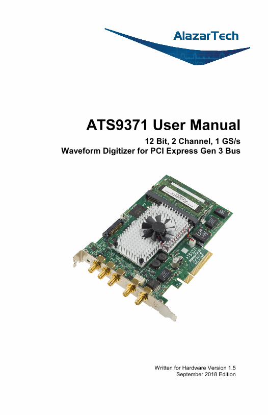
ATS9371 User Manual 12 Bit, 2 Channel, 1 GS/s
Waveform Digitizer for PCI Express Gen 3 Bus
Written for Hardware Version 1.5 September 2018 Edition
ATS9371 User Manual i
Copyright © 2018 Alazar Technologies Inc.. All rights reserved.
Alazar Technologies Inc. Contact Information
AlazarTech, Inc.
6600 Trans-Canada Highway
Suite 310
Pointe-Claire, QC
Canada H9R 4S2
Telephone: (514) 426-4899
Fax: (514) 426-2723
E-mail: [email protected]
Web site: www.alazartech.com
To comment on the documentation for ATS9371, send e-mail to [email protected].
Information required when contacting AlazarTech for technical support:
Owned by:
Serial Number:
Purchase Date:
Purchased From:
Software Driver Version:
SDK Version:
ATS-GPU Version:
ATS-GMA Version:
AlazarDSO® Version:
Operating System:
ii ATS9371 User Manual
Important Information
Warranty
The AlazarTech ATS®9371 is warranted against defects in materials and workmanship for a period of one year from the date of shipment, as evidenced by receipts or other documentation. Alazar Technologies, Inc. (hereafter “AlazarTech”) will, at its option, repair or replace equipment that proves to be defective during the warranty period. This warranty includes parts and labor.
The media on which you receive AlazarTech software are warranted not to fail to execute programming instructions, due to defects in materials and workmanship, for a period of 90 days from date of shipment, as evidenced by receipts or other documentation. AlazarTech will, at its option, repair or replace software media that do not execute programming instructions if AlazarTech receives notice of such defects during the warranty period. AlazarTech does not warrant that the operation of the software shall be uninterrupted or error free.
A Return Material Authorization (RMA) number must be obtained from the factory and clearly marked on the outside of the package before any equipment will be accepted for warranty work. AlazarTech will pay the shipping costs of returning to the owner parts that are covered by warranty.
AlazarTech believes that the information in this document is accurate. The document has been carefully reviewed for technical accuracy. In the event that technical or typographical errors exist, AlazarTech reserves the right to make changes to subsequent editions of this document without prior notice to holders of this edition. AlazarTech may also make improvements and/or changes in the products and/or programs described in this document at any time. The reader should consult AlazarTech if errors are suspected. In no event shall AlazarTech be liable for any damages arising out of or related to this document or the information contained in it. The latest user manual can be found on the AlazarTech web page at www.alazartech.com/support/downloads.htm.
ATS9371 User Manual iii
EXCEPT AS SPECIFIED HEREIN, ALAZARTECH MAKES NO WARRANTIES, EXPRESS OR IMPLIED, AND SPECIFICALLY DISCLAIMS ANY WARRANTY OF MERCHANTABILITY OR FITNESS FOR A PARTICULAR PURPOSE. CUSTOMER’S RIGHT TO RECOVER DAMAGES CAUSED BY FAULT OR NEGLIGENCE ON THE PART OF ALAZARTECH SHALL BE LIMITED TO THE AMOUNT THERETOFORE PAID BY THE CUSTOMER. ALAZARTECH WILL NOT BE LIABLE FOR DAMAGES RESULTING FROM LOSS OF DATA, PROFITS, USE OF PRODUCTS, OR INCIDENTAL OR CONSEQUENTIAL DAMAGES, EVEN IF ADVISED OF THE POSSIBILITY THEREOF. This limitation of the liability of AlazarTech will apply regardless of the form of action, whether in contract or tort, including negligence. Any action against AlazarTech must be brought within one year after the cause of action accrues. AlazarTech shall not be liable for any delay in performance due to causes beyond its reasonable control. The warranty provided herein does not cover damages, defects, malfunctions, or service failures caused by owner’s failure to follow the AlazarTech installation, operation, or maintenance instructions; owner’s modification of the product; owner’s abuse, misuse, or negligent acts; and power failure or surges, fire, flood, accident, actions of third parties, or other events outside reasonable control.
Copyright
Under the copyright laws, this publication may not be reproduced or transmitted in any form, electronic or mechanical, including photocopying, recording, storing in an information retrieval system, or translating, in whole or in part, without the prior written consent of AlazarTech.
Registered Trademarks
AlazarTech®, AlazarTech ATS®, AlazarDSO®, AlazarStream®, and AlazarPC® are registered trademarks of Alazar Technologies, Inc. MATLAB is a trademark and/or registered trademark of The MathWorks, Inc. LabVIEW is a trademark and/or registered trademark of National Instruments. Windows is a trademark and/or registered trademark of Microsoft Corporation in the U.S. and/or other countries. Linux is a registered trademark of Linus Torvalds. CUDA is a trademark and/or registered trademark of NVIDIA Corporation in the U.S. and/or other countries. Radeon is a trademark of Advanced Micro Devices, Inc. OpenCL is a trademark of Apple Inc.Product and company names mentioned herein are trademarks, registered trademarks, or trade names of their respective owners.
iv ATS9371 User Manual
Warning Regarding Use of AlazarTech Products 1. ALAZARTECH PRODUCTS ARE NOT DESIGNED WITH
COMPONENTS AND TESTING FOR A LEVEL OF RELIABILITY SUITABLE FOR USE IN OR IN CONNECTION WITH SURGICAL IMPLANTS OR AS CRITICAL COMPONENTS IN ANY LIFE SUPPORT SYSTEMS WHOSE FAILURE TO PERFORM CAN REASONABLY BE EXPECTED TO CAUSE SIGNIFICANT INJURY TO A HUMAN.
2. IN ANY APPLICATION, INCLUDING THE ABOVE, RELIABILITY OF OPERATION OF THE SOFTWARE PRODUCTS CAN BE IMPAIRED BY ADVERSE FACTORS, INCLUDING BUT NOT LIMITED TO FLUCTUATIONS IN ELECTRICAL POWER SUPPLY, COMPUTER HARDWARE MALFUNCTIONS, COMPUTER OPERATING SYSTEM SOFTWARE FITNESS, FITNESS OF COMPILERS AND DEVELOPMENT SOFTWARE USED TO DEVELOP AN APPLICATION, INSTALLATION ERRORS, SOFTWARE AND HARDWARE COMPATIBILITY PROBLEMS, MALFUNCTIONS OR FAILURES OF ELECTRONIC MONITORING OR CONTROL DEVICES, TRANSIENT FAILURES OF ELECTRONIC SYSTEMS (HARDWARE AND/OR SOFTWARE), UNANTICIPATED USES OR MISUSES, OR ERRORS ON THE PART OF THE USER OR APPLICATIONS DESIGNER (ADVERSE FACTORS SUCH AS THESE ARE HEREAFTER COLLECTIVELY TERMED “SYSTEM FAILURES”). ANY APPLICATION WHERE A SYSTEM FAILURE WOULD CREATE A RISK OF HARM TO PROPERTY OR PERSONS (INCLUDING THE RISK OF BODILY INJURY AND DEATH) SHOULD NOT BE RELIANT SOLELY UPON ONE FORM OF ELECTRONIC SYSTEM DUE TO THE RISK OF SYSTEM FAILURE. TO AVOID DAMAGE, INJURY, OR DEATH, THE USER OR APPLICATION DESIGNER MUST TAKE REASONABLY PRUDENT STEPS TO PROTECT AGAINST SYSTEM FAILURES, INCLUDING BUT NOT LIMITED TO BACK-UP OR SHUT DOWN MECHANISMS. BECAUSE EACH END-USER SYSTEM IS CUSTOMIZED AND DIFFERS FROM ALAZARTECH’s TESTING PLATFORMS AND BECAUSE A USER OR APPLICATION DESIGNER MAY USE ALAZARTECH PRODUCTS IN COMBINATION WITH OTHER PRODUCTS IN A MANNER NOT EVALUATED OR CONTEMPLATED BY ALAZARTECH, THE USER OR APPLICATION DESIGNER IS ULTIMATELY RESPONSIBLE FOR VERIFYING AND VALIDATING THE SUITABILITY OF ALAZARTECH PRODUCTS WHENEVER ALAZARTECH PRODUCTS ARE INCORPORATED IN A SYSTEM OR APPLICATION, INCLUDING, WITHOUT LIMITATION, THE APPROPRIATE DESIGN, PROCESS AND SAFETY LEVEL OF SUCH SYSTEM OR APPLICATION.

ATS9371 User Manual v
Compliance
FCC/Canadian Interference-Causing Equipment Standard (ICES-003) Compliance* Determining FCC Class
The Federal Communications Commission (FCC) has rules to protect wireless communications from interference. The FCC places digital electronics into two classes. These classes are known as Class A (for use in industrial-commercial locations only) or Class B (for use in residential or commercial locations). Depending on where it is operated, this product could be subject to restrictions in the FCC rules. (In Canada, the department of Innovation, Science and Economic Development (ISED), regulates wireless interference in much the same way.)
Digital electronics emit weak signals during normal operation that can affect radio, television, or other wireless products. By examining the product you purchased, you can determine the FCC Class and therefore which of the two FCC/ISED Warnings apply in the following sections. (Some products may not be labeled at all for FCC; if so, the reader should then assume these are Class A devices.)
FCC Class A products only display a simple warning statement of one paragraph in length regarding interference and undesired operation. Most of our products are FCC Class A. The FCC rules have restrictions regarding the locations where FCC Class A products can be operated.
FCC Class B products display either a FCC ID code, starting with the letters EXN, or the FCC Class B compliance mark.
Consult the FCC website http://www.fcc.gov for more information.
FCC/ISED Warnings
This equipment generates and uses radio frequency energy and, if not installed and used in strict accordance with the instructions in this manual and the CE Mark Declaration of Conformity**, may cause interference to radio and television reception. Classification requirements are the same for the Federal Communications Commission (FCC) and Innovation, Science and Economic Development (ISED) Canada.
Changes or modifications not expressly approved by AlazarTech Inc. could void the user’s authority to operate the equipment under the FCC/ISED Rules.

vi ATS9371 User Manual
Class A Federal Communications Commission
This equipment has been tested and found to comply with the limits for a Class A digital device, pursuant to part 15 of the FCC Rules. These limits are designed to provide reasonable protection against harmful interference when the equipment is operated in a commercial environment. This equipment generates, uses, and can radiate radio frequency energy and, if not installed and used in accordance with the instruction manual, may cause harmful interference to radio communications. Operation of this equipment in a residential area is likely to cause harmful interference in which case the user will be required to correct the interference at his own expense.
Innovation, Science and Economic Development Canada
This Class A digital apparatus meets all requirements of the Canadian Interference-Causing Equipment Standard (ICES-003). Cet appareil numérique de la classe A respecte toutes les exigences du Règlement sur le matériel brouilleur du Canada.
ATS9371 User Manual vii
Compliance to EU Directives
Readers in the European Union (EU) must refer to the Manufacturer's Declaration of Conformity (DoC) for information** pertaining to the CE Mark compliance scheme. The Manufacturer includes a DoC for most every hardware product except for those bought for OEMs, if also available from an original manufacturer that also markets in the EU, or where compliance is not required as for electrically benign apparatus or cables.
To obtain the DoC for this product, click Declaration of Conformity at www.alazartech.com/support/documents.htm. This web page lists all DoCs by product family. Select the appropriate product to download or read the DoC.
* Certain exemptions may apply in the USA, see FCC Rules §15.103 Exempted devices, and §15.105(c). Also available in sections of CFR 47.
** The CE Mark Declaration of Conformity will contain important supplementary information and instructions for the user or installer.
Environmental Compliance
Alazar Technologies Inc., hereby certifies that this product is RoHS compliant, as defined by Directive 2015/863/EU (RoHS 3) of the European Parliament and of the Council of 31 March 2015 on the restriction of the use of certain hazardous substances in electrical and electronic equipment. All manufacturing has been done using RoHS-compliant components and lead-free soldering.
viii ATS9371 User Manual
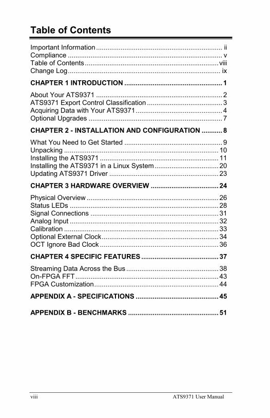
Table of Contents Important Information ................................................................... ii Compliance .................................................................................. v Table of Contents ....................................................................... viii Change Log ................................................................................. ix CHAPTER 1 INTRODUCTION .................................................... 1 About Your ATS9371 ................................................................... 2 ATS9371 Export Control Classification ........................................ 3 Acquiring Data with Your ATS9371 .............................................. 4 Optional Upgrades ....................................................................... 7 CHAPTER 2 - INSTALLATION AND CONFIGURATION ........... 8 What You Need to Get Started .................................................... 9 Unpacking .................................................................................. 10 Installing the ATS9371 ............................................................... 11 Installing the ATS9371 in a Linux System .................................. 20 Updating ATS9371 Driver .......................................................... 23 CHAPTER 3 HARDWARE OVERVIEW .................................... 24 Physical Overview ...................................................................... 26 Status LEDs ............................................................................... 28 Signal Connections .................................................................... 31 Analog Input ............................................................................... 32 Calibration .................................................................................. 33 Optional External Clock .............................................................. 34 OCT Ignore Bad Clock ............................................................... 36 CHAPTER 4 SPECIFIC FEATURES ......................................... 37 Streaming Data Across the Bus ................................................. 38 On-FPGA FFT ............................................................................ 43 FPGA Customization .................................................................. 44 APPENDIX A - SPECIFICATIONS ............................................ 45
APPENDIX B - BENCHMARKS ................................................ 51
ATS9371 User Manual ix
Change Log
This is the first edition of this manual

ATS9371 User Manual 1
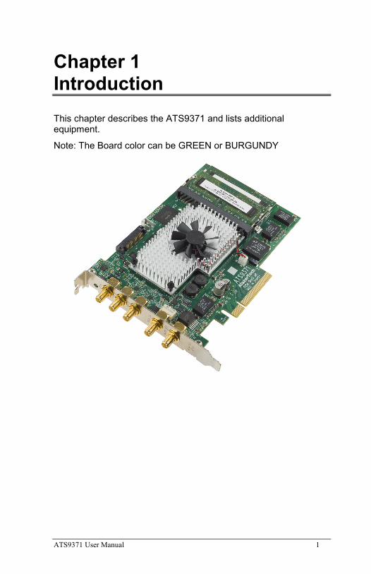
Chapter 1 Introduction This chapter describes the ATS9371 and lists additional equipment.
Note: The Board color can be GREEN or BURGUNDY
2 ATS9371 User Manual
About Your ATS9371
Thank you for your purchase of an ATS9371. This PCI Express (PCIe Gen3 x8) based waveform digitizer has the following features:
• Two 12-bit resolution analog input channels
• Real-time sampling rate of 1 GS/s to 1 KS/s with internal clock and 1 GS/s to 300 MS/s with external clock (1 GS/s to 100 MS/s with screened external clock)
• Uses on-board SO-DIMM RAM as a very deep FIFO
• Streaming of acquired data to PC host memory at 6.8 GB/s (exact rate is motherboard dependent)
• 1 GHz analog input bandwidth
• Half-length PCI Express (8 lane) card
• External trigger input channel with software-selectable level and slope
• DC coupling and fixed 50 Ω input impedance for analog inputs
• Pre-trigger and Post-Trigger Capture with Multiple Record capability
• NIST- or CNRC-traceable calibration
• Dual DMA engines for best latency protection against Windows and Linux operating systems
• Fully asynchronous software driver for fastest DMA with least CPU overhead
All ATS9371 digitizers follow industry-standard Plug and Play specifications on all platforms and offer seamless integration with compliant systems.
Detailed specifications of the ATS9371 digitizers are listed in Appendix A, Specifications.
ATS9371 User Manual 3
ATS9371 Export Control Classification
According to the Export Controls Division of Government of Canada, ATS9371 is currently not controlled for export from Canada. Its export control classification is N8, which is equivalent to ECCN EAR99. ATS9371 can be shipped freely outside of Canada, with the exception of countries listed on the Area Control List and Sanctions List.
Furthermore, if the end-use of ATS9371, in part or in its entirety, is related to the development or deployment of weapons of mass destruction, AlazarTech is obliged to apply for an export permit.
4 ATS9371 User Manual
Acquiring Data with Your ATS9371
You can acquire data either programmatically by writing an application for your ATS9371 or interactively with the AlazarDSO software.
If you want to integrate the ATS9371 in your test and measurement or embedded OEM application, you can program the digitizer using C/C++, Python, MATLAB® or LabVIEW® for Windows® or Linux® operating systems.
Windows operating systems supported are Windows 10, Windows 8, Windows 7, Windows Server 2013, Windows Server 2010, and Windows Server 2008 R2. Both 32 bit and 64 bit Windows operating systems are supported.
Binary drivers for most of the popular Linux distributions, such as CentOS, Ubuntu, etc. are available. Users can download the binary driver for their specific distribution by choosing from the available drivers here: ftp://[email protected]/outgoing/linux
Only 64 bit Linux operating systems are supported.
Other Linux distributions may also be supported on a case by case basis. Please contact [email protected] for more details. You must include the full output of uname -a command from your target Linux system in your email.
The AlazarTech engineering team may be able to generate an appropriate driver for a nominal fee, if applicable.
For using a programming language to acquire data from your ATS9371, you must purchase the ATS-SDK package.
ATS9371 User Manual 5
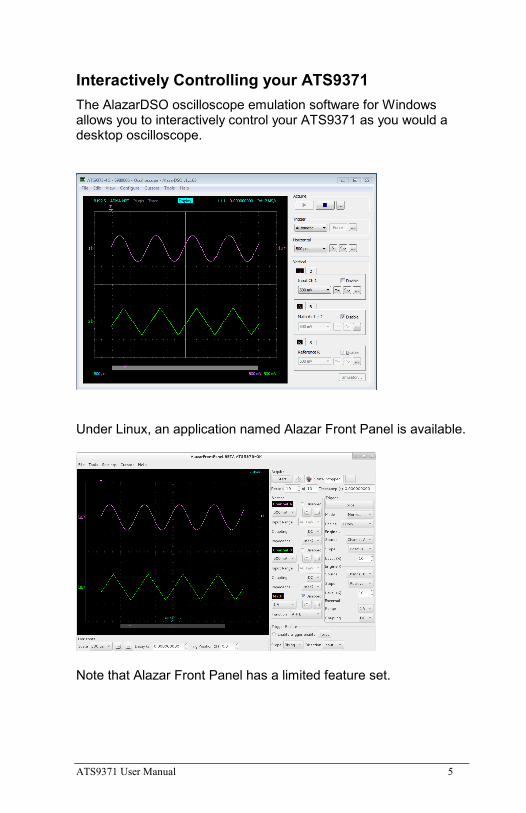
Interactively Controlling your ATS9371 The AlazarDSO oscilloscope emulation software for Windows allows you to interactively control your ATS9371 as you would a desktop oscilloscope.
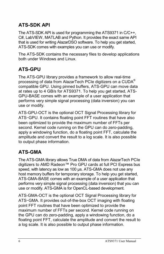
Under Linux, an application named Alazar Front Panel is available.
Note that Alazar Front Panel has a limited feature set.
6 ATS9371 User Manual
ATS-SDK API The ATS-SDK API is used for programming the ATS9371 in C/C++, C#, LabVIEW, MATLAB and Python. It provides the exact same API that is used for writing AlazarDSO software. To help you get started, ATS-SDK comes with examples you can use or modify.
The ATS-SDK contains the necessary files to develop applications both under Windows and Linux.
ATS-GPU The ATS-GPU library provides a framework to allow real-time processing of data from AlazarTech PCIe digitizers on a CUDA® compatible GPU. Using pinned buffers, ATS-GPU can move data at rates up to 4 GB/s for ATS9371. To help you get started, ATS-GPU-BASE comes with an example of a user application that performs very simple signal processing (data inversion) you can use or modify.
ATS-GPU-OCT is the optional OCT Signal Processing library for ATS-GPU. It contains floating point FFT routines that have also been optimized to provide the maximum number of FFTs per second. Kernel code running on the GPU can do zero-padding, apply a windowing function, do a floating point FFT, calculate the amplitude and convert the result to a log scale. It is also possible to output phase information.
ATS-GMA The ATS-GMA library allows True DMA of data from AlazarTech PCIe digitizers to AMD Radeon™ Pro GPU cards at full PCI Express bus speed, with latency as low as 100 μs. ATS-GMA does not use any host memory buffers for temporary storage. To help you get started, ATS-GMA-BASE comes with an example of a user application that performs very simple signal processing (data inversion) that you can use or modify. ATS-GMA is for OpenCL-based development.
ATS-GMA-OCT is the optional OCT Signal Processing library for ATS-GMA. It provides out-of-the-box OCT imaging with floating point FFT routines that have been optimized to provide the maximum number of FFTs per second. Kernel code running on the GPU can do zero-padding, apply a windowing function, do a floating point FFT, calculate the amplitude and convert the result to a log scale. It is also possible to output phase information.
ATS9371 User Manual 7
Optional Upgrades
AlazarTech offers the following upgrades and accessories for use with your ATS9371 digitizer:
• ATS9371: External Clock Upgrade (300 MHz to 1 GHz)
• ATS9371: Screened External Clock Upgrade (100 MHz to 1 GHz)
8 ATS9371 User Manual
Chapter 2 - Installation and Configuration This chapter describes how to unpack, install, and configure your ATS9371.
ATS9371 User Manual 9
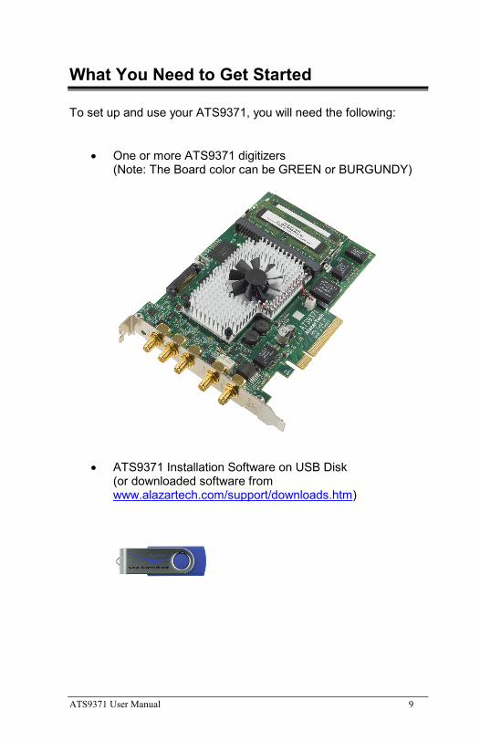
What You Need to Get Started
To set up and use your ATS9371, you will need the following:
• One or more ATS9371 digitizers (Note: The Board color can be GREEN or BURGUNDY)
• ATS9371 Installation Software on USB Disk (or downloaded software from www.alazartech.com/support/downloads.htm)
10 ATS9371 User Manual
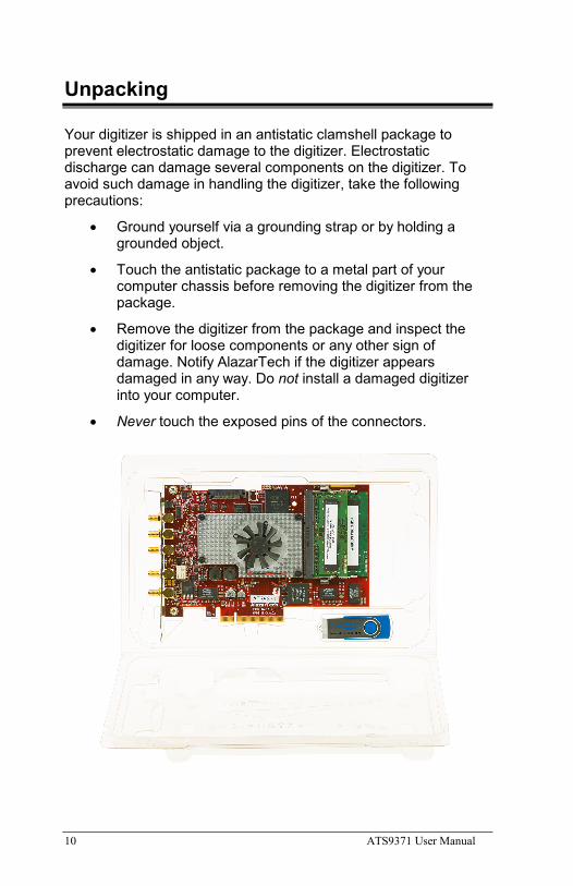
Unpacking
Your digitizer is shipped in an antistatic clamshell package to prevent electrostatic damage to the digitizer. Electrostatic discharge can damage several components on the digitizer. To avoid such damage in handling the digitizer, take the following precautions:
• Ground yourself via a grounding strap or by holding a grounded object.
• Touch the antistatic package to a metal part of your computer chassis before removing the digitizer from the package.
• Remove the digitizer from the package and inspect the digitizer for loose components or any other sign of damage. Notify AlazarTech if the digitizer appears damaged in any way. Do not install a damaged digitizer into your computer.
• Never touch the exposed pins of the connectors.
ATS9371 User Manual 11
Installing the ATS9371
There are four main steps involved in installation:
1. Physically install the digitizer(s) in your computer.
2. Install ATS9371 software driver
3. Install AlazarDSO software that allows you to setup the hardware, acquire signals and view and archive them
4. Optionally, install:
a. The ATS-SDK software development kit, which enables you to programmatically control the ATS9371
b. The ATS-GPU library, which enables you to perform real-time processing of data from the ATS9371 on a CUDA® compatible GPU
c. The ATS-GMA library, which enables you to DMA data from the ATS9371 on an AMD Radeon Pro GPU card for OpenCL™-based development
The following paragraphs will guide you through this process in a step-by-step manner.
12 ATS9371 User Manual
1. Physically install the digitizer in your computer Identify an unused PCI Express slot on your motherboard. As per PCI Express specification, the 8-lane ATS9371 card is compatible with any 8-lane or 16-lane connector on the motherboard. Make sure that your computer is powered off before you attempt to insert the ATS9371 digitizer in one of the free PCI Express slots. For best noise performance, leave as much room as possible between your ATS9371 and other hardware. Always screw the digitizer bracket to the chassis in order to create a stable and robust connection to chassis ground. In the absence of such a connection, ATS9371 is not guaranteed to operate within the specifications listed elsewhere in this manual.
Some motherboards may have a 16-lane connector, but only one or four of the lanes is connected to the motherboard chipset. Motherboard manufacturers refer to this as “Mechanically 16-lane, electrically 1 lane”. ATS9371 is fully compatible with such motherboards, but the data throughput across PCI Express bus will be limited by the number of lanes.
Please note that the PCI Express Revision has to be supported by both your motherboard and your CPU model. For example, the ASRock X79Extreme11 motherboard supports PCIe Gen 3, but the Intel i7-3820 CPU only supports PCIe Gen 2. A system made of these two components will only support PCIe Gen 2.
ATS9371 User Manual 13
2. Install ATS9371 software driver Linux users: skip to Installing the ATS9371 in a Linux System
The following instructions guide you through the process of installing the ATS9371 in a computer running Windows 10, 8, 7, Windows Server 2013, Windows Server 2010, or Windows Server 2008 R2 operating systems.
Note that the images of the dialog boxes shown below were taken from a Windows 7 computer. Computers running other versions of Windows may have slightly different dialog boxes.
When you first boot up the computer, the plug-n-play Windows operating system will detect the presence of a new PCI card and will attempt to install the device driver if found on the computer.
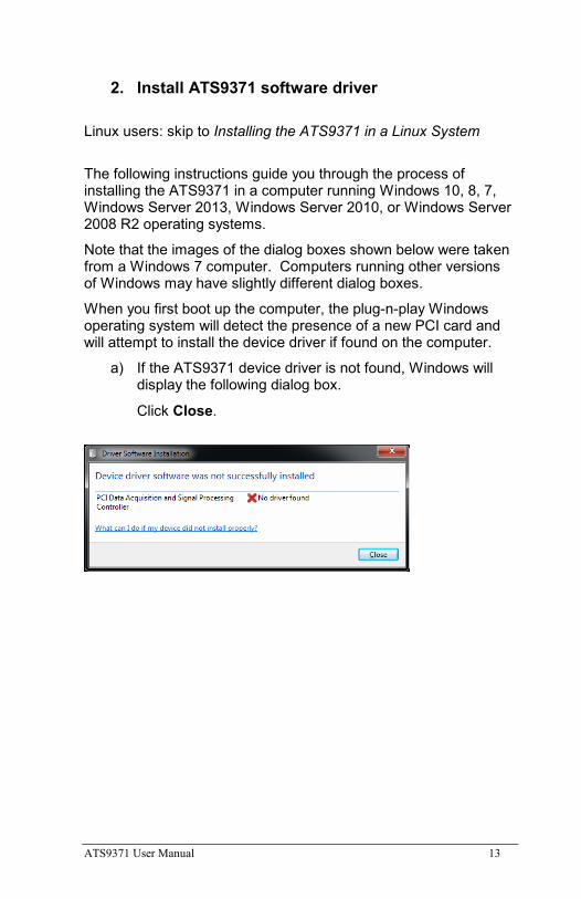
a) If the ATS9371 device driver is not found, Windows will display the following dialog box.
Click Close.
14 ATS9371 User Manual
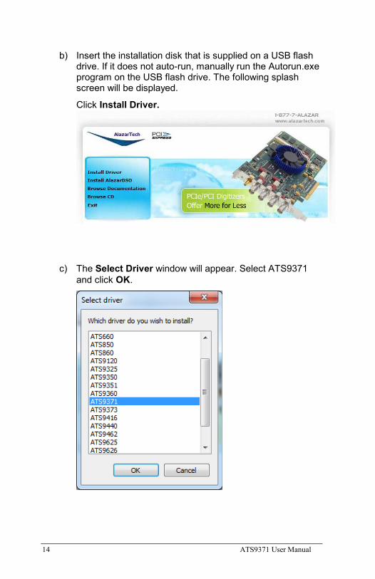
b) Insert the installation disk that is supplied on a USB flash drive. If it does not auto-run, manually run the Autorun.exe program on the USB flash drive. The following splash screen will be displayed.
Click Install Driver.
c) The Select Driver window will appear. Select ATS9371 and click OK.
ATS9371 User Manual 15
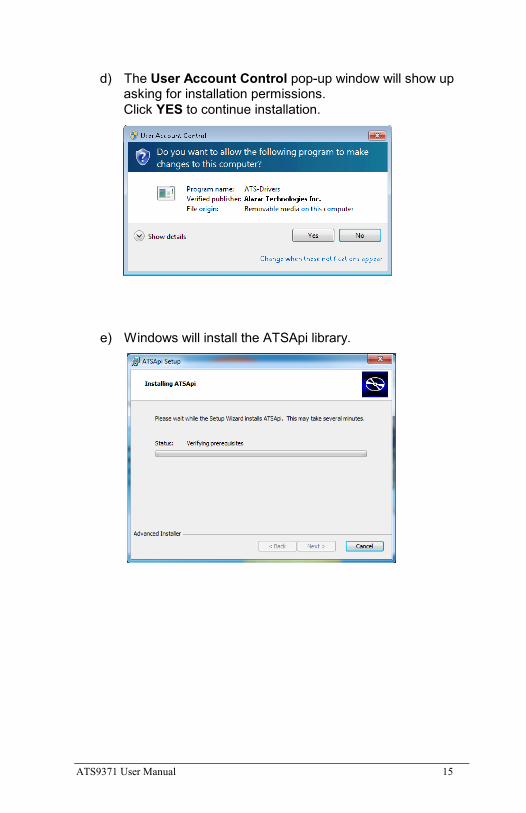
d) The User Account Control pop-up window will show up asking for installation permissions. Click YES to continue installation.
e) Windows will install the ATSApi library.
16 ATS9371 User Manual
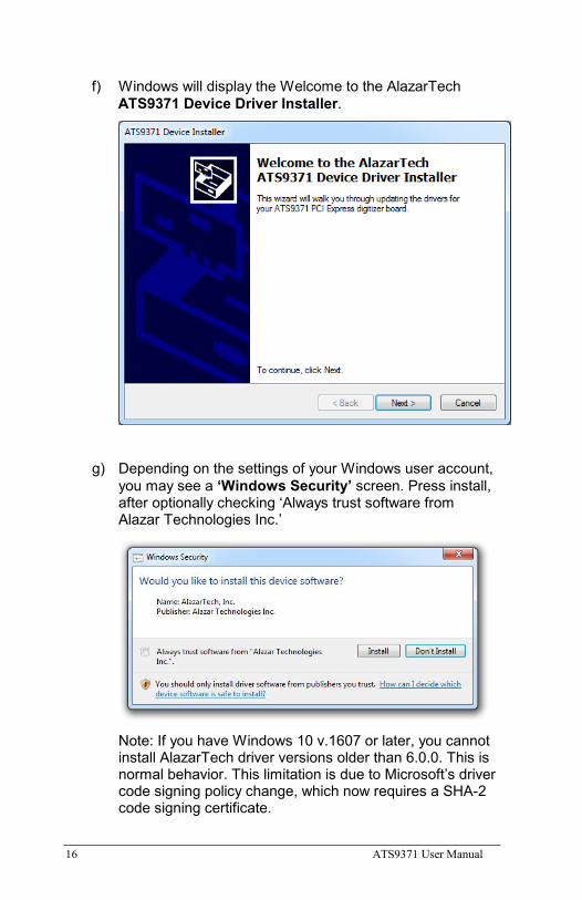
f) Windows will display the Welcome to the AlazarTech ATS9371 Device Driver Installer.
g) Depending on the settings of your Windows user account, you may see a ‘Windows Security’ screen. Press install, after optionally checking ‘Always trust software from Alazar Technologies Inc.’
Note: If you have Windows 10 v.1607 or later, you cannot install AlazarTech driver versions older than 6.0.0. This is normal behavior. This limitation is due to Microsoft’s driver code signing policy change, which now requires a SHA-2 code signing certificate.
ATS9371 User Manual 17
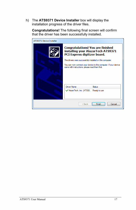
h) The ATS9371 Device Installer box will display the installation progress of the driver files.
Congratulations! The following final screen will confirm that the driver has been successfully installed.

18 ATS9371 User Manual
3. Install AlazarDSO software that allows you to setup the hardware, acquire signals and view and archive them
If you are installing from the USB flash drive shipped with the ATS9371 digitizer, run the Autorun.exe:
• Click on Install AlazarDSO
• Follow the instructions on the screen.
If you are installing AlazarDSO after having downloaded the installation file from AlazarTech website:
• Download AlazarDSO installation file from www.alazartech.com/support/downloads.htm
• Unzip the file downloaded in the previous step.
• Browse to the folder that contains the unzipped file, AlazarDsoSetup.exe
• Run this executable file and follow the instructions on the screen.
ATS9371 User Manual 19
4. Optionally, install the ATS-SDK and ATS-GPU or ATS-GMA software
Insert the ATS-SDK CD or ATS-GPU or ATS-GMA CD. Software installation will start automatically.
If, for any reason, installation does not start automatically:
• For ATS-SDK, run the ATS-SDK-Setup-7.x.x.exe.
• For ATS-GPU, run the ATS-GPU-x.x.x-win64.exe, then run ATS-SDK-Setup-7.x.x.exe. ATS-SDK is required for ATS-GPU. If you already have ATS-SDK installed on your system, please install the latest ATS-SDK included with your ATS-GPU.
• For ATS-GMA, run the ATS-GMA-x.x.x-win64.exe, then run ATS-SDK-Setup-7.x.x.exe. ATS-SDK is required for ATS-GMA. If you already have ATS-SDK installed on your system, please install the latest ATS-SDK included with your ATS-GMA.
Follow the instructions on the screen.
Note that you must have already installed the ATS9371 drivers for any of the sample programs included with the ATS-SDK or ATS-GPU or ATS-GMA to work properly.
In order to receive the 1 year of support and maintenance included with your ATS-SDK, ATS-GPU, or ATS-GMA, use the serial number provided on the CD envelope(s) and register your product(s) at: www.alazartech.com/UserHome?tab=2.
20 ATS9371 User Manual
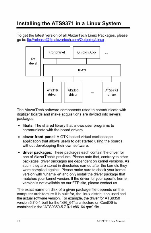
Installing the ATS9371 in a Linux System
To get the latest version of all AlazarTech Linux Packages, please go to: ftp://[email protected]/Outgoing/Linux
The AlazarTech software components used to communicate with digitizer boards and make acquisitions are divided into several packages:
• libats: The shared library that allows user programs to communicate with the board drivers.
• alazar-front-panel: A GTK-based virtual oscilloscope application that allows users to get started using the boards without developping their own software.
• driver packages: These packages each contain the driver for one of AlazarTech's products. Please note that, contrary to other packages, driver packages are dependent on kernel versions. As such, they are stored in directories named after the kernels they were compiled against. Please make sure to check your kernel version with “uname -a" and only install the driver package that matches your kernel version. If the driver for your specific kernel version is not available on our FTP site, please contact us.
The exact name on disk of a given package file depends on the computer architecture it is built for, the linux distribution used and the actual software version. For example, the driver for ATS9350 version 5.7.0-1 built for the “x86_64” architecture on CentOS is contained in the “ATS9350-5.7.0-1.x86_64.rpm” file.
ATS9371 User Manual 21
Installation Instructions: AlazarTech packages can be installed using the standard tools of Linux distributions, e.g. yum/dnf on CentOS/RHEL and Fedora, and apt/aptitude on Debian/Ubuntu. For more information, refer to the documentation of your Linux distribution.
The ATS-SDK product contains an extra software package, called ats-devel, for your Linux distribution containing the following components:
1. A programmer’s guide for the boards
2. Header files for C/C++ programming, and library wrappers for other programming languages
3. Code samples that demonstrate typical acquisition configurations
Note: The ats-devel package is not architecture specific. A “noarch” text replaces the usual x86<sub>64</sub> or i386 field.
On development machines, AlazarTech recommends to install all the packages provided with the boards. On the other hand, in a production environment, the “ats-devel” and “alazar-front-panel” packages are optional. It is enough to install the “libats” package in addition to user-developped applications and the drivers corresponding to the boards used to get a working system.
To install an ATS9371 on your Linux system, follow the next steps:
1. Connect one or several ATS9371 in your computer
2. Start your computer, and install all the software packages for your ATS9371.
3. If you purchased the optional ATS-GPU library, you should have received the software package for your Linux distribution. Contact [email protected] if you have not received the appropriate software package.
Note: If you already have installed different AlazarTech products in your computer, only the driver package will be new. Be sure to use the latest version of all packages though, as for example older libraries may not be compatible with all the features of recent drivers.
22 ATS9371 User Manual
Installation Troubleshooting If you are experiencing difficulties using AlazarTech digitizers on your Linux system, please ensure that the following packages are all installed:
• alazar-front-panel
• libats
• driver package for your board (with the right kernel version)
If these packages are installed, but the AlazarFrontPanel application does not detect your board, please run the following command at a prompt:
$ lsmod | grep ATS
If this command shows no output, the driver for your board did not start. To know more, run the following command:
$ /usr/local/AlazarTech/bin/ATS9371.rc start
In the output of this command, if you see a "version mismatch" error, it indicates that the kernel version you are running does not correspond to that with which the driver package was built.
If there is a "Required key not available" message in the output, it indicates that the driver will not load because of a signature issue. On kernels where the EFI_SECURE_BOOT_SIG_ENFORCE config is enabled, third-party drivers cannot load if UEFI Secure Boot is active. The simplest solution is to disable secure boot in the UEFI BIOS settings.
ATS9371 User Manual 23
Updating ATS9371 Driver
From time to time, AlazarTech updates the device drivers for its products. These updates may be required for product enhancements or for bug fixes.
This section of the manual takes you through the steps required to update the device driver for the ATS9371 PCI Express waveform digitizer.
In other words, this section shows you how to install a newer version of the driver, when you already have a previous version of the driver installed on your machine.
1. Download the latest driver from AlazarTech’s website: www.alazartech.com/support/downloads.htm
2. Unzip the downloaded file to a local folder
3. Run the resulting installation file (*.exe extension). For example, the installation file for driver version 6.00.01 is called ATS9371_Driver_V6.0.1.exe, and follow the instructions.
Please note:
AlazarTech recommends that you register your ATS9371 in order to receive notifications of new driver releases. Take note of your serial number and go to www.alazartech.com/UserHome?tab=2.
You must be logged into your My AlazarTech account in order to register a product. If you do not have an account, sign-up for one here: www.alazartech.com/Regstart
24 ATS9371 User Manual
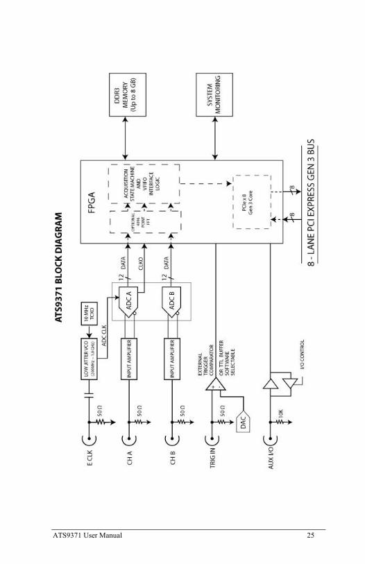
Chapter 3 Hardware Overview This chapter includes an overview of the ATS9371, explains the operation of each functional unit making up your ATS9371, and describes the signal connections.
Following is a high-level block diagram of ATS9371.
ATS9371 User Manual 25
26 ATS9371 User Manual
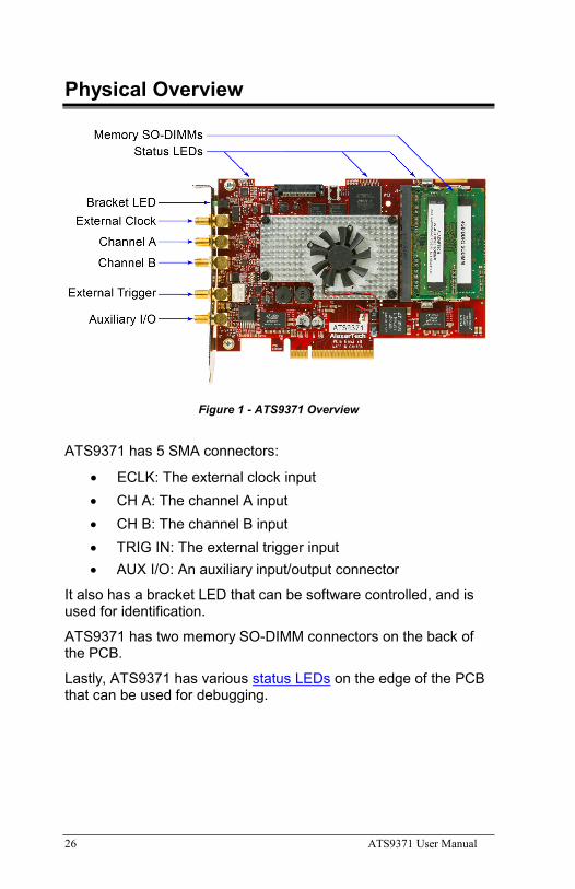
Physical Overview
Figure 1 - ATS9371 Overview
ATS9371 has 5 SMA connectors:
• ECLK: The external clock input • CH A: The channel A input • CH B: The channel B input • TRIG IN: The external trigger input • AUX I/O: An auxiliary input/output connector
It also has a bracket LED that can be software controlled, and is used for identification.
ATS9371 has two memory SO-DIMM connectors on the back of the PCB.
Lastly, ATS9371 has various status LEDs on the edge of the PCB that can be used for debugging.
ATS9371 User Manual 27
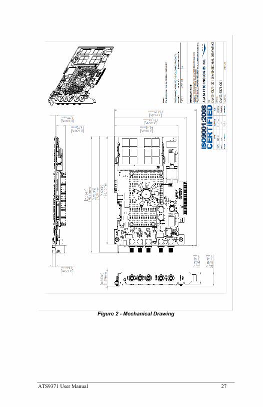
Figure 2 - Mechanical Drawing
28 ATS9371 User Manual
Status LEDs
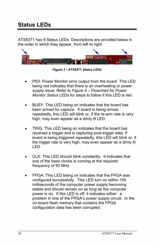
ATS9371 has 9 Status LEDs. Descriptions are provided below in the order in which they appear, from left to right:
Figure 3 - ATS9371 Status LEDs
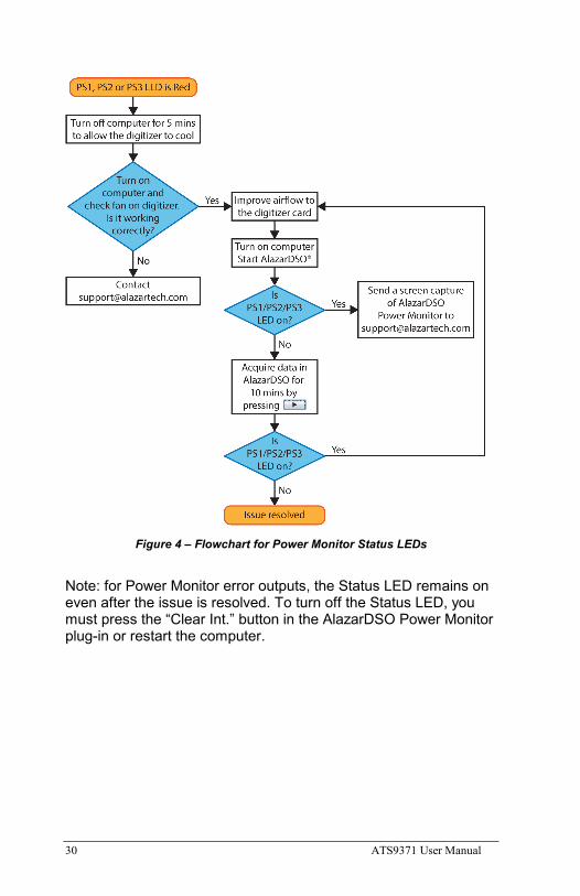
• PS3: Power Monitor error output from the board. This LED being red indicates that there is an overheating or power supply issue. Refer to Figure 4 – Flowchart for Power Monitor Status LEDs for steps to follow if this LED is red.
• BUSY: This LED being on indicates that the board has been armed for capture. If board is being armed repeatedly, this LED will blink or, if the re-arm rate is very high, may even appear as a dimly lit LED.
• TRIG: This LED being on indicates that the board has received a trigger and is capturing post-trigger data. If board is being triggered repeatedly, this LED will blink or, if the trigger rate is very high, may even appear as a dimly lit LED
• CLK: This LED should blink constantly. It indicates that one of the base clocks is running at the required frequency of 50 MHz.
• FPGA: This LED being on indicates that the FPGA was configured successfully. This LED turn on within 100 milliseconds of the computer power supply becoming stable and should remain on as long as the computer power is on. If this LED is off, it indicates either: a problem in one of the FPGA’s power supply circuit; or the on-board flash memory that contains the FPGA configuration data has been corrupted.
ATS9371 User Manual 29
• LINK: This LED being ON indicates that a PCIe link has been negotiated between the board and the motherboard. The exact time at which this LED turns on is dependent on the motherboard and its BIOS. Typically, this LED will turn on a few seconds after the FPGA is configured. If the FPGA LED is on but LINK LED does not turn on, it indicates either: the motherboard slot is not enabled by the CPU or the BIOS; or there is a problem in the transceiver power supplies; or one or more of the transceiver coupling capacitors along the gold-fingers on the secondary side have been damaged.
• MEM: This LED indicates that on-board memory is detected by the board. When the software driver is loaded at the start of an application, it forces a full memory test. If the test is completed successfully, this LED is turned on, otherwise it remains off. If this LED is off, remove and reinsert the SO-DIMMs.
• PS2: Power Monitor error output from the board. This LED being red indicates that there is an overheating or power supply issue. Refer to Figure 4 – Flowchart for Power Monitor Status LEDs for steps to follow if this LED is red.
• PS1: Power Monitor error output from the board. This LED being red indicates that there is an overheating or power supply issue. Refer to Figure 4 – Flowchart for Power Monitor Status LEDs for steps to follow if this LED is red.
30 ATS9371 User Manual
Figure 4 – Flowchart for Power Monitor Status LEDs
Note: for Power Monitor error outputs, the Status LED remains on even after the issue is resolved. To turn off the Status LED, you must press the “Clear Int.” button in the AlazarDSO Power Monitor plug-in or restart the computer.
ATS9371 User Manual 31
Signal Connections
You can use CH A and CH B to digitize data as well as to trigger an acquisition.
Use the TRIG IN input for an external trigger only; data on the TRIG channel cannot be digitized.
If External Clock Upgrade is installed on your ATS9371, use the ECLK input for clocking the ATS9371 in applications that require an external clock. Consult the chapter Optional External Clock for details on various types of clocking schemes available.
AUX I/O connector can be used as the following I/O’s:
Outputs:
• Trigger Output
• Pacer (programmable clock) Output
• Digital Output
Inputs:
• Trigger Enable Input
• Digital Input
• Clock Switchover Control
32 ATS9371 User Manual
Analog Input
The two analog input channels are referenced to common ground in bipolar mode. These settings are fixed; therefore, neither the reference nor the polarity of input channels can be changed. You cannot use CH A or CH B to make differential measurements or measure floating signals unless you subtract the digital waveforms in software.
For accurate measurements, make sure the signal being measured is referenced to the same ground as your ATS9371 by attaching the cable’s ground shield to the signal ground.
The External Trigger input (labeled TRIG IN) has a ±2.5 V analog Input range with 50 Ω input impedance, or a 3.3 V TTL (5 V-compliant) input with 6.6 kΩ impedance.
Monolithic 12-bit analog-to-digital converted
ATS9371 uses a dual analog-to-digital converter (ADC) with a maximum conversion rate of 1 GS/s.
If you use an external clock, you must follow all the timing specifications on the external clock as described in Appendix A, Specifications.
Multiple Record Acquisition
The ATS9371 allows the capture of multiple records into the on-board memory. This allows you to capture rapidly occurring triggers in OCT, ultrasound or radar applications.
Specifying Record Length
Record Length is specified in number of sample points. It must be a minimum of 256 points and must be a multiple of 128.
Specifying Pretrigger Depth
You can acquire pre-trigger data up to 4088 samples in dual channel and 8176 in single channel. Minimum value for pre-trigger amount is 0.
Specifying Record Count
User can specify the number of records that must be captured into host PC memory. The minimum value must be 1.
There is no upper limit on how many records you can capture in one acquisition.
ATS9371 User Manual 33
Calibration
Calibration is the process of minimizing measurement errors by making small circuit adjustments.
All ATS9371 digitizers come factory calibrated to the levels indicated in Appendix A, Specifications. Note that AlazarTech calibration is fully NIST- or CNRC-traceable.
However, your digitizer needs to be periodically recalibrated in order to maintain its specified accuracy. This calibration due date is listed on the CALIBRATION sticker affixed to your ATS9371 digitizer.
Externally recalibrate the ATS9371 when this calibration interval has expired.
This requires three very simple steps:
1. Verify whether or not ATS9371 is still within its specifications. If it is, then your calibration can be extended by another one-year period
2. If not, perform calibration, i.e. make adjustments to the circuit until it is within specifications again
3. If any adjustments have been made, verify if the ATS9371 is within specifications
Recalibration must be performed at AlazarTech factory.
34 ATS9371 User Manual
Optional External Clock
ATS9371 PCI Digitizer optionally allows you to supply the ADC clock. This option is extremely important in many RF applications in which phase measurements must be made between the inputs themselves or between the inputs and an external event.
Another application that requires external clock is Optical Coherence Tomography (OCT) that sometimes requires analog sampling to take place relative to an MZI clock, sometimes also known as k-clock.
Driving high performance ADCs must be done carefully, as any injection of phase jitter through ADC clocks will result in reduction in data conversion quality.
Aside from phase noise, the clock signal for a pipelined ADC must also have a duty cycle close to 50%. This maximizes the dynamic performance of the ADC. See Fast External Clock section below for more details.
External clock input impedance is fixed at 50 Ohms.
External clock input is always AC-coupled.
There are two types of External Clock supported by ATS9371:
• Fast External Clock
• 10 MHz Clock Reference
The following paragraphs describe the two types of External Clock input and outline the restrictions on each of them.
Fast External Clock This setting must be used when the external clock frequency is in the range of 1 GHz down to Lower Clock Limit. If you purchased ATS9371: Standard External Clock Upgrade, Lower Clock Limit is 300 MHz.
If you purchased ATS9371: Screened External Clock Upgrade, Lower Clock Limit is 100 MHz.
It is highly recommended that the Fast External Clock signal have a duty cycle of 50% +/- 5%. However, duty cycle specification can be substantially relaxed at lower frequencies.
If the External Clock supplied is lower than the Lower Clock Limit, measurement quality may be compromised. Measurement errors
ATS9371 User Manual 35
may include gain errors, signal discontinuities and general signal distortion.
External Clock must be an at least ±200 mV sine wave or square wave signal. Maximum amplitude for external clock is ±1 V.
The receiver circuit for Fast External Clock is a high speed ECL receiver that translates the input signal into a PECL (Positive ECL) clock signal that features very fast rise times.
Since Fast External Clock is always ac-coupled and selfbiased, there is no need for the user to set the external clock level.
10 MHz Clock Reference ATS9371 allows the user to synchronize the sampling clock to an external 10 MHz reference signal. This is useful in many RF applications.
Reference clock frequency must be 10 MHz +/- 0.1 MHz. Amplitude can be a ±200 mV sine or square wave.
In 10 MHz PLL external clock mode, the ATS9371 can generate any sample clock frequency between 300 MHz and 1 GHz that is a multiple of 1 MHz.
36 ATS9371 User Manual
OCT Ignore Bad Clock
AlazarTech has developed OCT Ignore Bad Clock, a technology that can effectively ignore the k-clock signal for a user-specified amount of time.
Users must call an API function that takes Good Clock Duration and Bad Clock Duration as input parameters. The user must determine the correct values for these parameters. Some laser manufacturers may be able to provide these parameters.
AlazarTech has created a software utility called IgnoreBadClock that lets the user confirm their Duration values using an oscilloscope.
See www.alazartech.com/Technology/OCT-Ignore-Bad-Clock for more information on this technology.
Note: You must have ATS-SDK version 7.1.3 or later as well as ATS9371 Firmware version 26.04 or later, and driver version 6.00.01 or later in order to use OCT Ignore Bad Clock.
ATS9371 User Manual 37
Chapter 4 Specific Features This section contains information about features specific to AlazarTech digitizers and ATS9371 in particular.
38 ATS9371 User Manual
Streaming Data Across the Bus
One of the most unique features of the ATS9371 is its on-board, dual-port acquisition memory that can act as a very deep Data FIFO and the associated Dual-DMA engine.
This combined by the advanced, fully asynchronous software driver allows data transfer to host PC memory without any appreciable “in-process” software involvement.
These features are particularly useful for applications that require:
a) Continuous, gapless data capture. Also known as “Data Streaming” to PC host memory or hard disk
or
b) Data capture from rapidly occurring triggers, also known as Pulse Repeat Frequency Captures or PRF Captures.
In order to understand these sophisticated features, let us first review some of the issues involved in transferring data under Windows or Linux operating systems.
The Effects of the Operating System Windows and most Linux distributions are not real-time operating systems, i.e. the operating system cannot guarantee a deterministic response time to an event, such as an interrupt or a software generated event.
This means that if software has to play any appreciable part in data transfer, then the data throughput cannot be guaranteed, as the operating system will have the last say as to when the data collection application will get the CPU cycles to execute the necessary commands.
Note that the above is true even if the digitizer claims to use Direct Memory Access (DMA) to do the actual transfer, but uses software commands to re-arm the digitizer. It is the re-arm command that will determine the overall data throughput.
Dual Port Memory The basic throughput problem faced by digitizers is that almost all of them use single-port memory, i.e. if you are reading data from the acquisition memory, you cannot capture into it and vice-versa.
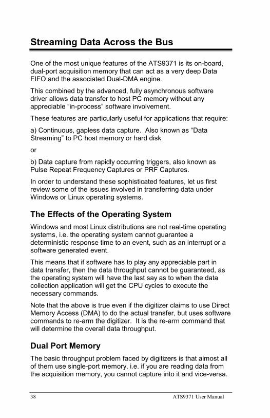
ATS9371 User Manual 39
This requires a software handshake which is heavily dependent on the operating system response time.
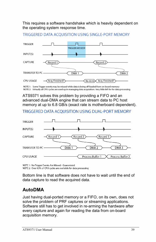
ATS9371 solves this problem by providing a FIFO and an advanced dual-DMA engine that can stream data to PC host memory at up to 6.8 GB/s (exact rate is motherboard dependent).
Bottom line is that software does not have to wait until the end of data capture to read the acquired data.
AutoDMA Just having dual-ported memory or a FIFO, on its own, does not solve the problem of PRF captures or streaming applications. Software still has to get involved in re-arming the hardware after every capture and again for reading the data from on-board acquisition memory.
40 ATS9371 User Manual
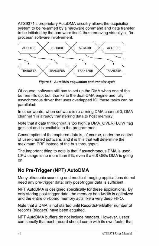
ATS9371’s proprietary AutoDMA circuitry allows the acquisition system to be re-armed by a hardware command and data transfer to be initiated by the hardware itself, thus removing virtually all “in-process” software involvement.
Figure 5 - AutoDMA acquisition and transfer cycle
Of course, software still has to set up the DMA when one of the buffers fills up, but, thanks to the dual-DMA engine and fully asynchronous driver that uses overlapped IO, these tasks can be paralleled.
In other words, when software is re-arming DMA channel 0, DMA channel 1 is already transferring data to host memory.
Note that if data throughput is too high, a DMA_OVERFLOW flag gets set and is available to the programmer.
Consumption of the captured data is, of course, under the control of user-created software, and it is this that will determine the maximum PRF instead of the bus throughput.
The important thing to note is that if asynchronous DMA is used, CPU usage is no more than 5%, even if a 6.8 GB/s DMA is going on.
No Pre-Trigger (NPT) AutoDMA Many ultrasonic scanning and medical imaging applications do not need any pre-trigger data: only post-trigger data is sufficient.
NPT AutoDMA is designed specifically for these applications. By only storing post-trigger data, the memory bandwidth is optimized and the entire on-board memory acts like a very deep FIFO.
Note that a DMA is not started until RecordsPerBuffer number of records (triggers) have been acquired.
NPT AutoDMA buffers do not include headers. However, users can specify that each record should come with its own footer that
ATS9371 User Manual 41
contains a 40-bit trigger timestamp. The footer is called NPT Footer.
More importantly, a BUFFER_OVERFLOW flag is asserted only if the entire on-board memory is used up. This provides a very substantial improvement over Traditional AutoDMA.
NPT AutoDMA can easily acquire data to PC host memory at the maximum sustained transfer rate of the motherboard without causing an overflow.
This is the recommended mode of operation for most ultrasonic scanning, OCT and medical imaging applications.
Continuous AutoDMA Continuous AutoDMA is also known as the data streaming mode.
In this mode, data starts streaming across the PCI bus as soon as the ATS9371 is armed for acquisition. It is important to note that triggering is disabled in this mode.
Continuous AutoDMA buffers do not include headers, so it is not possible to get trigger time-stamps.
A BUFFER_OVERFLOW flag is asserted only if the entire on-board memory is used up.
The amount of data to be captured is controlled by counting the number of buffers acquired. Acquisition is stopped by an AbortCapture command.
Continuous AutoDMA can easily acquire data to PC host memory at the maximum sustained transfer rate of the motherboard without causing an overflow.
This is the recommended mode for very long signal recording.
Triggered Streaming AutoDMA Triggered Streaming AutoDMA is virtually the same as Continuous mode, except the data transfer across the bus is held off until a trigger event has been detected.
Triggered Streaming AutoDMA buffers do not include headers, so it is not possible to get trigger time-stamps.
A BUFFER_OVERFLOW flag is asserted only if the entire on-board memory is used up.
42 ATS9371 User Manual
As in Continuous mode, the amount of data to be captured is controlled by counting the number of buffers acquired.
Acquisition is stopped by an AbortCapture command.
Triggered Streaming AutoDMA can easily acquire data to PC host memory at the maximum sustained transfer rate of the motherboard without causing an overflow.
This is the recommended mode for RF signal recording that has to be started at a specific time, e.g. based on a GPS pulse.
Stream To Memory AlazarDSO features a free ‘Stream To Memory’ module which allows it’s users to acquire data to computer RAM and to analyse it or save it to disk later. This is very useful in cases where the acquisition data rate is higher than the disk writing speed, but the total acquisition size is less than the free RAM of the computer.
This module is accessed by clicking on Tools >> Stream To Memory…
ATS9371 User Manual 43
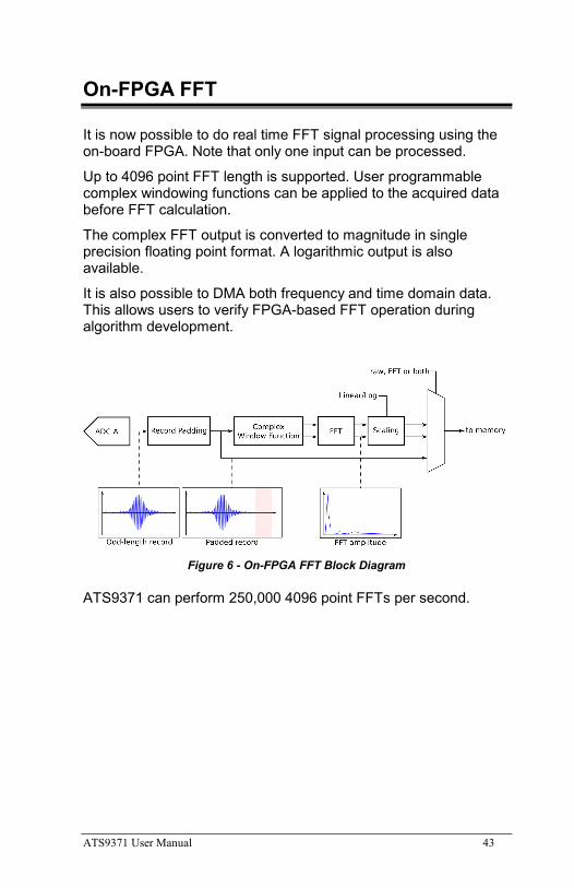
On-FPGA FFT
It is now possible to do real time FFT signal processing using the on-board FPGA. Note that only one input can be processed.
Up to 4096 point FFT length is supported. User programmable complex windowing functions can be applied to the acquired data before FFT calculation.
The complex FFT output is converted to magnitude in single precision floating point format. A logarithmic output is also available.
It is also possible to DMA both frequency and time domain data. This allows users to verify FPGA-based FFT operation during algorithm development.
Figure 6 - On-FPGA FFT Block Diagram
ATS9371 can perform 250,000 4096 point FFTs per second.
44 ATS9371 User Manual
FPGA Customization
ATS9371’s FPGA is not user-programmable, but AlazarTech provides a service of FPGA customization.
For more information, contact the AlazarTech factory.
ATS9371 User Manual 45
Appendix A - Specifications This appendix lists the specifications of the ATS9371. These specifications are typical at 25 °C unless otherwise stated. The operating temperature range is 0 to 55 °C.
Minimum Requirements OS Windows 10, Windows 8.x, Windows 7,
Windows Server 2013, Windows Server 2010 or Windows Server 2008 R2 (both 32 and 64 bit), or one of the Supported Linux Distributions
RAM 16 GB
HDD 100 MB of free hard disk space
PCIe Slot One free PCIe slot that is mechanically x8 or x16 (must be Gen 3 slot to achieve full data throughput).
Recommended Motherboard Specifications PCI Express revision 3 or higher
PCI Express Transceiver speed 8 Gbps
PCI Express Port lanes 8
Please note that the PCI Express Revision has to be supported by both your motherboard and your CPU model. For example, the ASRock X79Extreme11 motherboard supports PCIe Gen 3, but the Intel i7-3820 CPU only supports PCIe Gen 2. A system made of these two components will only support PCIe Gen 2.
Power Requirements +12 V 1.5 A, typical
+3.3 V 3.0 A, typical
Physical Size Single slot, half-length PCIe card
(4.377 inches x 6.5 inches excluding the connectors protruding from the front panel)
Weight 250 g
46 ATS9371 User Manual
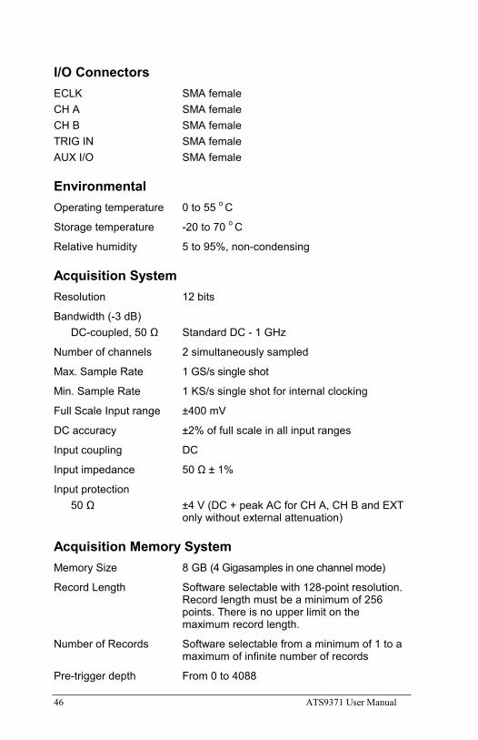
I/O Connectors ECLK SMA female CH A SMA female CH B SMA female TRIG IN SMA female AUX I/O SMA female
Environmental Operating temperature 0 to 55 o C
Storage temperature -20 to 70 o C
Relative humidity 5 to 95%, non-condensing
Acquisition System Resolution 12 bits
Bandwidth (-3 dB) DC-coupled, 50 Ω Standard DC - 1 GHz
Number of channels 2 simultaneously sampled
Max. Sample Rate 1 GS/s single shot
Min. Sample Rate 1 KS/s single shot for internal clocking
Full Scale Input range ±400 mV
DC accuracy ±2% of full scale in all input ranges
Input coupling DC
Input impedance 50 Ω ± 1%
Input protection 50 Ω ±4 V (DC + peak AC for CH A, CH B and EXT
only without external attenuation)
Acquisition Memory System Memory Size 8 GB (4 Gigasamples in one channel mode)
Record Length Software selectable with 128-point resolution. Record length must be a minimum of 256 points. There is no upper limit on the maximum record length.
Number of Records Software selectable from a minimum of 1 to a maximum of infinite number of records
Pre-trigger depth From 0 to 4088
ATS9371 User Manual 47
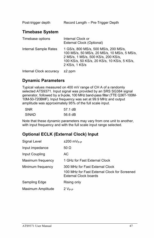
Post-trigger depth Record Length – Pre-Trigger Depth
Timebase System Timebase options Internal Clock or
External Clock (Optional)
Internal Sample Rates 1 GS/s, 800 MS/s, 500 MS/s, 200 MS/s, 100 MS/s, 50 MS/s, 20 MS/s, 10 MS/s, 5 MS/s, 2 MS/s, 1 MS/s, 500 KS/s, 200 KS/s, 100 KS/s, 50 KS/s, 20 KS/s, 10 KS/s, 5 KS/s, 2 KS/s, 1 KS/s
Internal Clock accuracy ±2 ppm
Dynamic Parameters Typical values measured on 400 mV range of CH A of a randomly selected ATS9371. Input signal was provided by an SRS SG384 signal generator, followed by a 9-pole, 100 MHz band-pass filter (TTE Q36T-100M-10M-50-720BMF). Input frequency was set at 99.9 MHz and output amplitude was approximately 95% of the full scale input.
SNR 57.1 dB SINAD 56.6 dB
Note that these dynamic parameters may vary from one unit to another, with input frequency and with the full scale input range selected.
Optional ECLK (External Clock) Input Signal Level ±200 mVP-P
Input impedance 50 Ω
Input Coupling AC
Maximum frequency 1 GHz for Fast External Clock
Minimum frequency 300 MHz for Fast External Clock 100 MHz for Fast External Clock for Screened External Clock boards
Sampling Edge Rising only
Maximum Amplitude 2 VP-P
48 ATS9371 User Manual
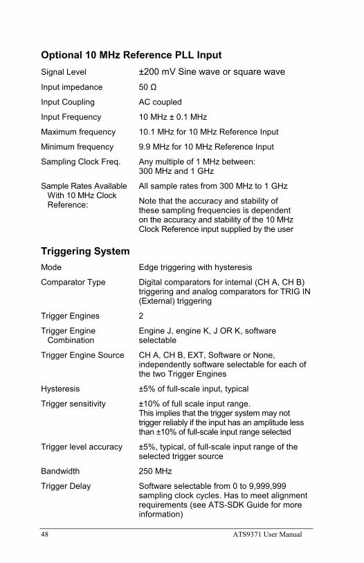
Optional 10 MHz Reference PLL Input Signal Level ±200 mV Sine wave or square wave
Input impedance 50 Ω
Input Coupling AC coupled
Input Frequency 10 MHz ± 0.1 MHz
Maximum frequency 10.1 MHz for 10 MHz Reference Input
Minimum frequency 9.9 MHz for 10 MHz Reference Input
Sampling Clock Freq. Any multiple of 1 MHz between: 300 MHz and 1 GHz
Sample Rates Available With 10 MHz Clock Reference:
All sample rates from 300 MHz to 1 GHz
Note that the accuracy and stability of these sampling frequencies is dependent on the accuracy and stability of the 10 MHz Clock Reference input supplied by the user
Triggering System Mode Edge triggering with hysteresis
Comparator Type Digital comparators for internal (CH A, CH B) triggering and analog comparators for TRIG IN (External) triggering
Trigger Engines 2
Trigger Engine Engine J, engine K, J OR K, software Combination selectable
Trigger Engine Source CH A, CH B, EXT, Software or None, independently software selectable for each of the two Trigger Engines
Hysteresis ±5% of full-scale input, typical
Trigger sensitivity ±10% of full scale input range. This implies that the trigger system may not trigger reliably if the input has an amplitude less than ±10% of full-scale input range selected
Trigger level accuracy ±5%, typical, of full-scale input range of the selected trigger source
Bandwidth 250 MHz
Trigger Delay Software selectable from 0 to 9,999,999 sampling clock cycles. Has to meet alignment requirements (see ATS-SDK Guide for more information)
ATS9371 User Manual 49
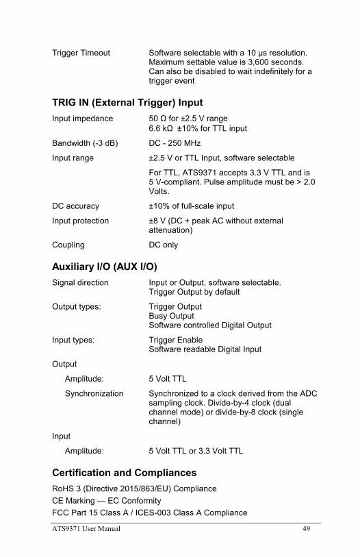
Trigger Timeout Software selectable with a 10 μs resolution. Maximum settable value is 3,600 seconds. Can also be disabled to wait indefinitely for a trigger event
TRIG IN (External Trigger) Input Input impedance 50 Ω for ±2.5 V range
6.6 kΩ ±10% for TTL input
Bandwidth (-3 dB) DC - 250 MHz
Input range ±2.5 V or TTL Input, software selectable
For TTL, ATS9371 accepts 3.3 V TTL and is 5 V-compliant. Pulse amplitude must be > 2.0 Volts.
DC accuracy ±10% of full-scale input
Input protection ±8 V (DC + peak AC without external attenuation)
Coupling DC only
Auxiliary I/O (AUX I/O) Signal direction Input or Output, software selectable.
Trigger Output by default
Output types: Trigger Output Busy Output Software controlled Digital Output
Input types: Trigger Enable Software readable Digital Input
Output
Amplitude: 5 Volt TTL
Synchronization Synchronized to a clock derived from the ADC sampling clock. Divide-by-4 clock (dual channel mode) or divide-by-8 clock (single channel)
Input
Amplitude: 5 Volt TTL or 3.3 Volt TTL
Certification and Compliances RoHS 3 (Directive 2015/863/EU) Compliance CE Marking — EC Conformity FCC Part 15 Class A / ICES-003 Class A Compliance
50 ATS9371 User Manual
Materials Supplied One ATS9371 PCI Express Card One ATS9371 Install Disk on USB flash drive
Supported Linux Distributions AlazarTech offers ATS9371 binary drivers for most of the popular Linux distributions, such as CentOS, Ubuntu,...
Users can download the binary driver for their specific distribution by choosing from the available drivers here:
ftp://[email protected]/outgoing/linux
All specifications are subject to change without notice
ATS9371 User Manual 51
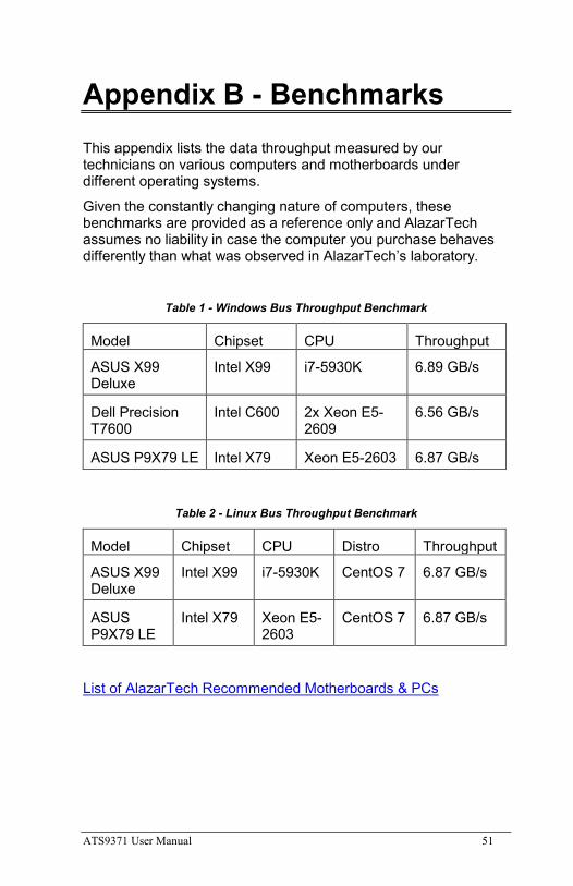
Appendix B - Benchmarks This appendix lists the data throughput measured by our technicians on various computers and motherboards under different operating systems.
Given the constantly changing nature of computers, these benchmarks are provided as a reference only and AlazarTech assumes no liability in case the computer you purchase behaves differently than what was observed in AlazarTech’s laboratory.
Table 1 - Windows Bus Throughput Benchmark
Model Chipset CPU Throughput
ASUS X99 Deluxe
Intel X99 i7-5930K 6.89 GB/s
Dell Precision T7600
Intel C600 2x Xeon E5-2609
6.56 GB/s
ASUS P9X79 LE Intel X79 Xeon E5-2603 6.87 GB/s
Table 2 - Linux Bus Throughput Benchmark
Model Chipset CPU Distro Throughput
ASUS X99 Deluxe
Intel X99 i7-5930K CentOS 7 6.87 GB/s
ASUS P9X79 LE
Intel X79 Xeon E5-2603
CentOS 7 6.87 GB/s
List of AlazarTech Recommended Motherboards & PCs

ALAZAR TECHNOLOGIES INC. 6600 Trans-Canada Highway Suite 310 Pointe-Claire, QC CANADA H9R 4S2
Tel: (514) 426-4899 Fax: (514) 426-2723
E-mail: [email protected] Web: www.alazartech.com