Embed Size (px)
Citation preview

ATS1190Smart Card Reader
Programming Manual
Version 2.0

Aritech and Tecom are Interlogix Companies
© 2001 Interlogix B.V.. All rights reserved. Interlogix B.V. grant the right to reprint this manual for internal use only. InterlogixB.V. reserves the right to change information without notice.
ATS1190 Programming Manual 1
CONTENTS
1. Introduction............................................................................................................................................ 2
2. Configuring the Smart Card Reader .................................................................................................... 32.1. Programming information in the Smart Card Reader.................................................................... 32.2. Setting the reader’s address.......................................................................................................... 52.3. Changing the LED on-line settings................................................................................................ 72.4. Changing the LED off-line operation ............................................................................................. 92.5. Setting Valid Card (LED) Flash ................................................................................................... 102.6. Enabling the night light ................................................................................................................ 112.7. Setting the Protocol options......................................................................................................... 122.8. Setting the beeper options........................................................................................................... 132.9. Setting the watchdog option ........................................................................................................ 142.10. Setting the relay option................................................................................................................ 152.11. Disabling the use of configuration or “option” cards.................................................................... 172.12. Setting the egress control............................................................................................................ 182.13. Restore factory defaults............................................................................................................... 192.14. Checking the last card badged.................................................................................................... 202.15. Setting-up credit usage and relay timing ..................................................................................... 20
Using credits........................................................................................................................... 20Basic requirements................................................................................................................. 20Explaining the items ............................................................................................................... 21
2.16. Checking the credit of the last card badged ................................................................................ 232.17. Setting the security mode............................................................................................................ 242.18. Checking the version number of the Smart Card Reader ........................................................... 25
3. Additional information ........................................................................................................................ 253.1. Extra feature: User definable format ........................................................................................... 253.2. Special notes ............................................................................................................................... 25
4. Glossary of terms ................................................................................................................................ 26
5. Index...................................................................................................................................................... 29
6. Programming map ............................................................................................................................... 30

2 ATS1190 Programming Manual
1. INTRODUCTION
The Aritech/Tecom Smart Card Reader (ATS1190) is a proximity card reader using smart card technology. Itoffers flexibility and a range of features never before packed into a proximity reader of its kind and size.
Main features:
• The Smart Card Reader can be connected to the system or local databus, Wiegand or Magnetic Stripeinterfaces with little or no configuration.
• The reader can be configured by Smart Cards with the aid of TITAN and the Smart Card programmer(ATS1620) or through its extensive menu system when connected to the system or local databus.
• The reader can accommodate up to 11,466 system codes and up to 65,535 user numbers.
• A user definable format permits system operators to produce their own formats using up to 112 bits ofdata.
• Basic set-up and programming for online access control.
Blue LED:- Door open- Disarmed
Comms:- LED control- Beeper control- Power
Red LED:- Door open- Armed
✍ The term ‘on-line’ means that the card reader is connected to a system or local databus, and ‘off-line’ means that the reader is connected to a Wiegand or Track 2 magnetic stripe interface. Thereader automatically switches to the ‘off-line’ mode if it does not receive valid databus data within 10seconds of power being applied.

ATS1190 Programming Manual 3
2. CONFIGURING THE SMART CARD READER
There are three ways to configure the Smart Card Reader:
1. Use a configuration card. This requires the smart card programmer (ATS1620) in combination with theATS8100 TITAN software package.
2. Through the ATS control panel menu when connected to the system databus.
3. Through the 4-Door DGP menu when connected to the local databus.
2.1. Programming information in the Smart Card ReaderMethod Procedure
1. Program a reader configurationcard using TITAN and the ATS1620smart card programmer to therequired set-up.
See the TITAN help menu for directions.
Connect the reader to the system or local databus or a 12 VDCsupply as described in the Installation Guide and badge theconfiguration card once. The reader will beep once. However,the reader will beep twice if the new set-up differs from thecurrent set-up.
If the configuration card is badged a second time and thereader is connected to the system or local databus, the readerwill beep its current address three times.
2. Connect the Smart Card Reader tothe system databus and poll thereader’s current address.
1. Go to control panel installer menu 3 – Arming Stations.
Select RAS to be Polled. Enter RAS address 16.
2. Go to control panel installer menu 28 – To RemoteDevices.
Press device type 2 (RAS) and enter RAS number 16. Thefollowing text appears:
3. Scroll through the Smart Card Reader’s main menu usingthe [ENTER] or [MENU*].
Select the menu options to configure the reader to yourrequirements. All the options available on the configurationcard are available in the menu system.
For more detail regarding the reader address, see Settingthe reader’s address.
3. Connect the reader to the localdatabus of the 4-Door DGP and pollthe reader’s current address.
1. Control panel installer menu 28 – To Remote Devices
Press device type 1 (DGP) and enter the DGP address ofthe 4-Door DGP to which the ATS1190 is connected (theDGP uses address 1 in this example). The display shows:
Tecom Smart Reader TS08700-Exit, Menu: _
#-Move On *-Move BackMenu: _

4 ATS1190 Programming Manual
Method Procedure2. Select menu 1 (DGP options).
3. Press [Enter] until this screen appears:
4. Enter the card reader address, e.g., 16 (by default) andpress [Enter].
5. To leave the DGP options menu, press [ENTER] until thedisplay shows:
6. Using [ENTER], move to menu 10.
7. Press [ENTER]. The display shows:
8. Enter 2 for RAS and press [ENTER].
9. Now enter the card reader RAS address as programmedunder step 4 and press [ENTER].
You can scroll through the Smart Card Reader’s main menuusing the [ENTER] or [MENU*].
Select the menu options to configure the reader to yourrequirements. All options available on the configuration card areavailable in the menu system.
For more detail regarding the reader address, see Setting thereader’s address.
1-DGP OptionsMenu: _
No RAS’s are being polledPoll RAS: _
1-DGP OptionsMenu: _
10-To Local DevicesMenu: _
Local Device Type: 1-DGP, 2-RASDevice Type: _
Sub-Remote RAS SetupRAS No: _
Tecom Smart Reader TS08700-Exit, Menu: _
16,Poll RAS: _

ATS1190 Programming Manual 5
2.2. Setting the reader’s addressThe Smart Card Reader is set to RAS address 16 by default. There are two methods to change the address.
1. Use a configuration card programmed with the smart card programmer ATS1620 and the ATS8100TITAN software package.
2. Use the Smart Card Reader menu.
Method Procedure1. Change the address by
programming a configuration cardusing the TITAN systemmanagement software and thesmart card programmer (ATS1620).
1. On the TITAN menu bar, select Admin > Card Programmer> Write reader config. card.
2. In the box labelled Reader Address type the requiredreader address (1 to 16 are allowed).
3. Place a configuration card or a blank card on the smartcard programmer and click the “Write” button.
4. Badge this card at the reader and check in menu 19-Installer programming, and menu 3-RAS Database that thereader is being polled.
5. Repeat the above steps with a different address for eachreader to be polled on the databus.
Note on programming in TITAN:� For more information on programming the reader
address in TITAN, see the online help page on the “CardWriter’s Setup” menu screen.
� Other options for the reader can be programmed at thesame moment the address is set.
6 ATS1190 Programming Manual
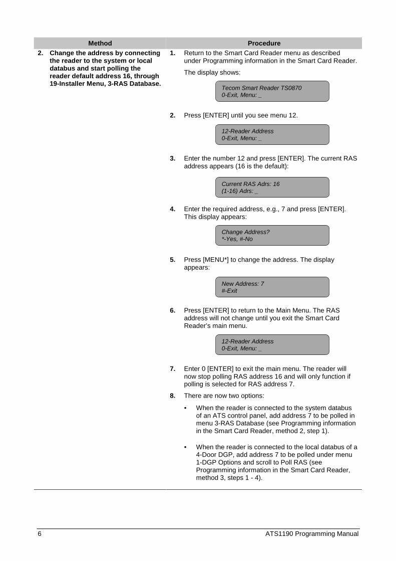
Method Procedure2. Change the address by connecting
the reader to the system or localdatabus and start polling thereader default address 16, through19-Installer Menu, 3-RAS Database.
1. Return to the Smart Card Reader menu as describedunder Programming information in the Smart Card Reader.
The display shows:
2. Press [ENTER] until you see menu 12.
3. Enter the number 12 and press [ENTER]. The current RASaddress appears (16 is the default):
4. Enter the required address, e.g., 7 and press [ENTER].This display appears:
5. Press [MENU*] to change the address. The displayappears:
6. Press [ENTER] to return to the Main Menu. The RASaddress will not change until you exit the Smart CardReader’s main menu.
7. Enter 0 [ENTER] to exit the main menu. The reader willnow stop polling RAS address 16 and will only function ifpolling is selected for RAS address 7.
8. There are now two options:
• When the reader is connected to the system databusof an ATS control panel, add address 7 to be polled inmenu 3-RAS Database (see Programming informationin the Smart Card Reader, method 2, step 1).
• When the reader is connected to the local databus of a4-Door DGP, add address 7 to be polled under menu1-DGP Options and scroll to Poll RAS (seeProgramming information in the Smart Card Reader,method 3, steps 1 - 4).
Tecom Smart Reader TS08700-Exit, Menu: _
12-Reader Address0-Exit, Menu: _
12-Reader Address0-Exit, Menu: _
Current RAS Adrs: 16(1-16) Adrs: _
Change Address?*-Yes, #-No
New Address: 7#-Exit
ATS1190 Programming Manual 7
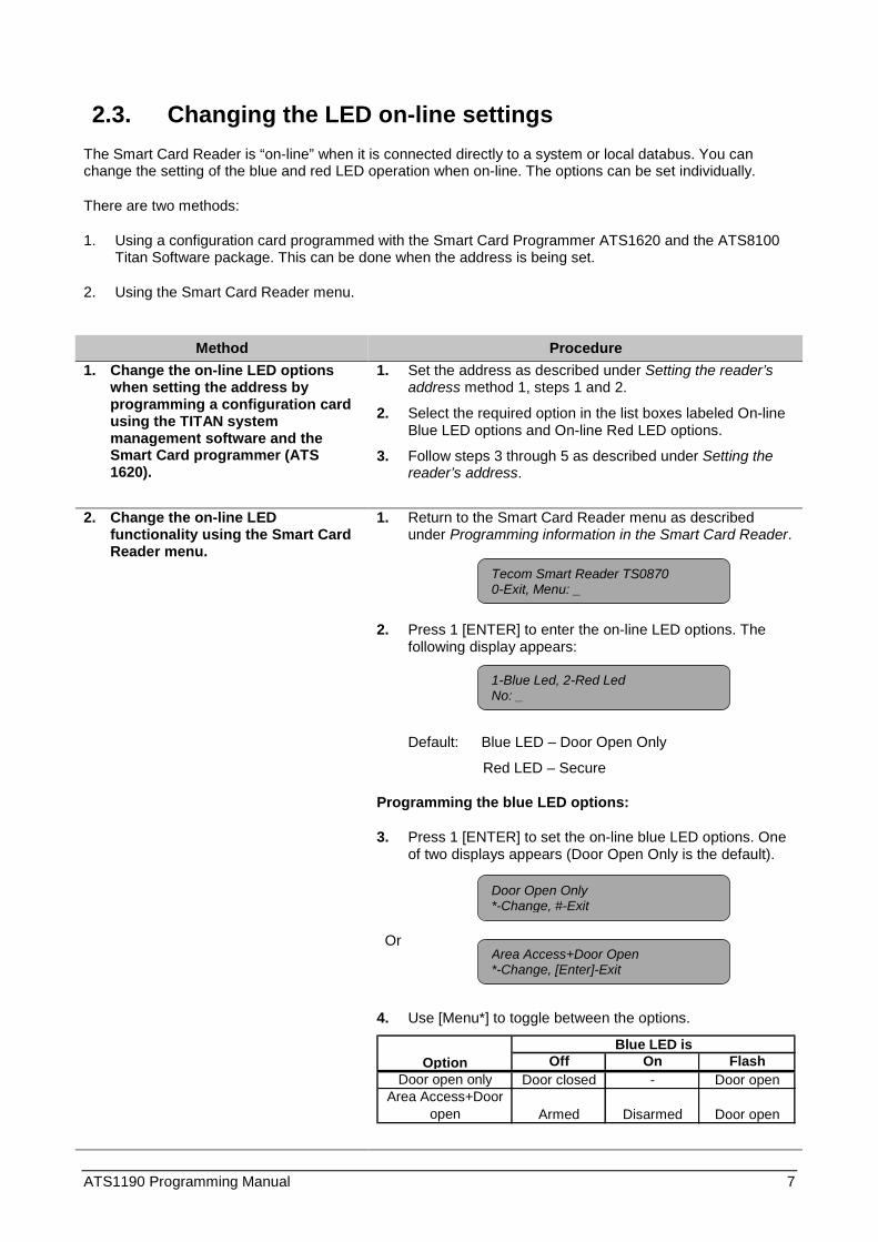
2.3. Changing the LED on-line settingsThe Smart Card Reader is “on-line” when it is connected directly to a system or local databus. You canchange the setting of the blue and red LED operation when on-line. The options can be set individually.
There are two methods:
1. Using a configuration card programmed with the Smart Card Programmer ATS1620 and the ATS8100Titan Software package. This can be done when the address is being set.
2. Using the Smart Card Reader menu.
Method Procedure1. Change the on-line LED options
when setting the address byprogramming a configuration cardusing the TITAN systemmanagement software and theSmart Card programmer (ATS1620).
1. Set the address as described under Setting the reader’saddress method 1, steps 1 and 2.
2. Select the required option in the list boxes labeled On-lineBlue LED options and On-line Red LED options.
3. Follow steps 3 through 5 as described under Setting thereader’s address.
2. Change the on-line LEDfunctionality using the Smart CardReader menu.
1. Return to the Smart Card Reader menu as describedunder Programming information in the Smart Card Reader.
2. Press 1 [ENTER] to enter the on-line LED options. Thefollowing display appears:
Default: Blue LED – Door Open Only
Red LED – Secure
Programming the blue LED options:
3. Press 1 [ENTER] to set the on-line blue LED options. Oneof two displays appears (Door Open Only is the default).
Or
4. Use [Menu*] to toggle between the options.
Off On FlashDoor open only Door closed - Door open
Area Access+Door open Armed Disarmed Door open
OptionBlue LED is
1-Blue Led, 2-Red LedNo: _
Area Access+Door Open*-Change, [Enter]-Exit
Door Open Only*-Change, #-Exit
Tecom Smart Reader TS08700-Exit, Menu: _
8 ATS1190 Programming Manual
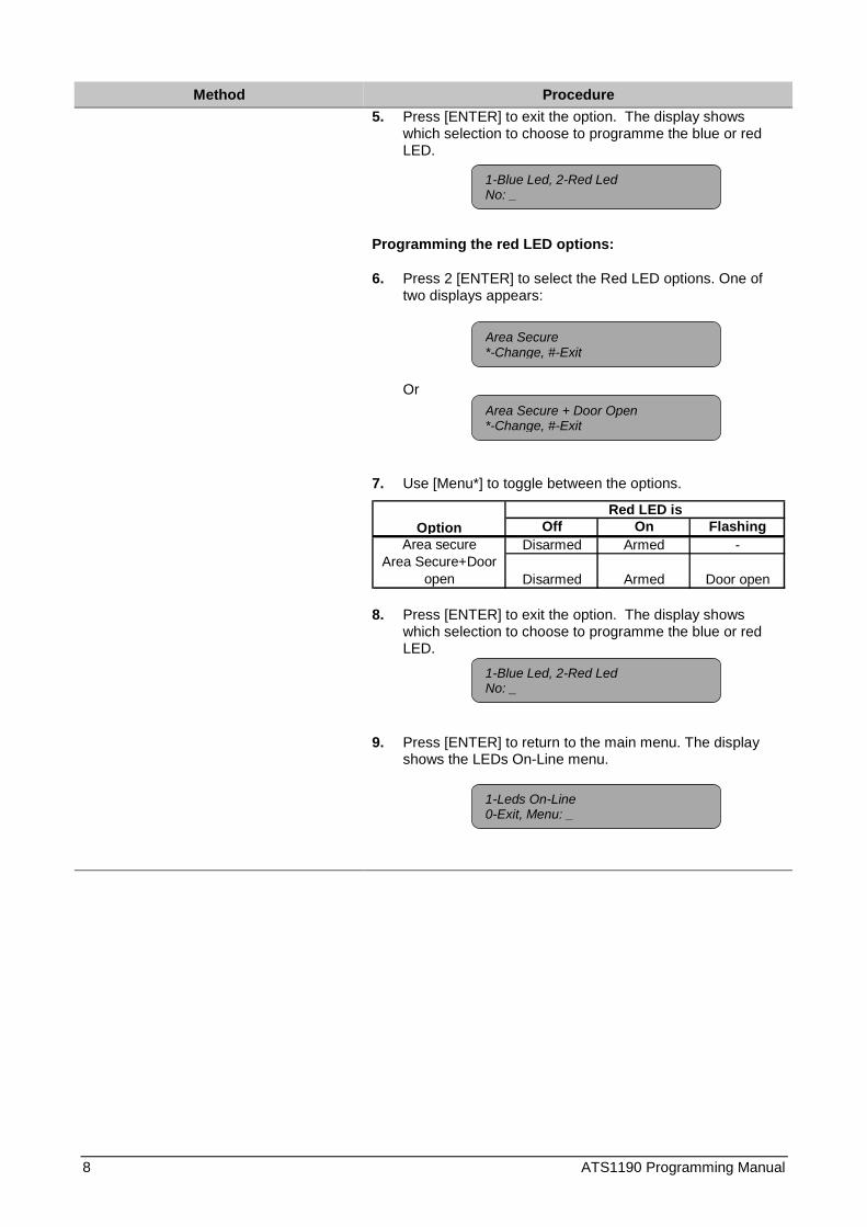
Method Procedure5. Press [ENTER] to exit the option. The display shows
which selection to choose to programme the blue or redLED.
Programming the red LED options:
6. Press 2 [ENTER] to select the Red LED options. One oftwo displays appears:
Or
7. Use [Menu*] to toggle between the options.
Off On FlashingArea secure Disarmed Armed -
Area Secure+Door open Disarmed Armed Door open
OptionRed LED is
8. Press [ENTER] to exit the option. The display showswhich selection to choose to programme the blue or redLED.
9. Press [ENTER] to return to the main menu. The displayshows the LEDs On-Line menu.
Area Secure + Door Open*-Change, #-Exit
1-Blue Led, 2-Red LedNo: _
Area Secure*-Change, #-Exit
1-Blue Led, 2-Red LedNo: _
1-Leds On-Line0-Exit, Menu: _

ATS1190 Programming Manual 9
2.4. Changing the LED off-line operationThe Smart Card Reader is “off-line” when it is connected to a Wiegand or magstripe interface. When off-line,the LEDs can be set using a one-wire or two-wire operation. There are two methods:
1. Using a configuration card programmed with the Smart Card Programmer ATS1620 and the ATS8100Titan Software package. This can be done when setting the address.
2. Using the Smart Card Reader menu.
Method Procedure1. Change the LED off-line operation
when setting the address byprogramming a configuration cardusing the TITAN systemmanagement software and theSmart Card programmer (ATS1620).
1. Set the address as described under Setting the reader’saddress method 1, steps 1 and 2.
2. Select the required option in the list box labelled Off-lineLED options.
3. Follow steps 3 through 5 as described under Setting thereader’s address.
2. Change the LED off-line operationusing the Smart Card Readermenu.
1. Return to the Smart Card Reader menu as describedunder Programming information in the Smart Card Reader.
2. Press 2 [ENTER] to enter the Off-line LED options. One oftwo screens appears:
Or
Default: Two-wire LED control
3. Use [Menu*] to toggle between the options.Option Operation
One-wire LED control Brown wire controls blue & red LEDTwo-wire LED control Red LED = brown wire; Blue LED = yellow wire
4. Press [ENTER] to exit the option. The display shows theLEDs Off-Line menu.
Note: In the off-line mode the brown and yellow wires controlthe LEDs. See the Smart Card Programmer Installation Guidefor further details.
Two Wire Led Control*-Change, #-Exit
One Wire Led Control*-Change, #-Exit
2- Leds Off-Line0-Exit, Menu: _
Tecom Smart Reader TS08700-Exit, Menu: _

10 ATS1190 Programming Manual
2.5. Setting Valid Card (LED) FlashThe Smart Card Reader allows for the blue LED to give a short flash when a valid card is badged (on duringcredit transactions). There are two ways to enable this option:
1. Using a configuration card programmed with the Smart Card Programmer ATS1620 and the ATS8100Titan Software package. This can be done when setting the address.
2. Using the Smart Card Reader menu.
Method Procedure1. Change the valid card flash
operation while setting the addressby programming a configurationcard using the TITAN systemmanagement software and theSmart Card programmer (ATS1620).
1. Set the address as described under Setting the reader’saddress method 1, steps 1 and 2.
2. To enable, tick the Valid card LED flash checkbox.
3. Follow steps 3 through 5 as described under Setting thereader’s address.
2. Change the valid card flashoperation using the Smart CardReader menu.
1. Return to the Smart Card Reader menu as describedunder Programming information in the Smart Card Reader.
2. Press 3 [ENTER] to enter the Valid Card Flash setting.One of two screens appear:
Or
Default: Flash Enabled
3. Use [Menu*] to toggle between the options.
4. Press [ENTER] to exit the option. The display will showValid Card Flash menu.
Exception: If a credit deduction was made from the card,the blue LED turns on for the duration of the transaction,regardless of this menu option. See the section on “CreditSet-up” for more details.
Flash Enabled*-Change, #-Exit
Flash Disabled*-Change, #-Exit
Tecom Smart Reader TS08700-Exit, Menu: _
3-Valid Card Flash0-Exit, Menu: _

ATS1190 Programming Manual 11
2.6. Enabling the night lightThe Smart Card Reader allows for the blue LED to faintly light up in order to show directions in a dark room.When the red or blue LED is active, the night light is off. There are two methods to enable this:
1. Using a configuration card programmed with the Smart Card Programmer ATS1620 and the ATS8100Titan Software package. This can be done at the same moment the address is set.
2. Using the Smart Card Reader menu.
Method Procedure1. Change the night light operation
when setting the address byprogramming a configuration cardusing the TITAN systemmanagement software and theSmart Card programmer (ATS1620).
1. Set the address as described under Setting the reader’saddress method 1, steps 1 and 2.
2. To enable, tick the Night Light checkbox.
3. Follow steps 3 through 5 as described under Setting thereader’s address.
2. Change the night light operationusing the Smart Card Readermenu.
1. Return to the Smart Card Reader menu as describedunder Programming information in the Smart Card Reader.
2. Press 4 [ENTER] to enter the Night Light setting. One oftwo screens appears:
Or
Default: Night Light Enabled
3. Use [Menu*] to toggle between the options.
4. Press [ENTER] to exit the option. The display shows theNight Light menu.
Night Light Enabled*-Change, #-Exit
Night Light Disabled*-Change, #-Exit
Tecom Smart Reader TS08700-Exit, Menu: _
4-Night Light0-Exit, Menu: _

12 ATS1190 Programming Manual
2.7. Setting the Protocol optionsThe Smart Card Reader supports different formats to transmit data. There are two methods to set therequired protocol:
1. Using a configuration card programmed with the Smart Card Programmer ATS1620 and the ATS8100Titan Software package. This can be done when setting the address.
2. Using the Smart Card Reader menu.
Method Procedure1. Change the protocol while setting
the address by programming aconfiguration card using the TITANsystem management software andthe Smart Card programmer (ATS1620).
1. Set the address as described under Setting the reader’saddress method 1, steps 1 and 2.
2. Select the required protocol from the list box labelledProtocol.
3. Follow steps 3 through 5 as described under Setting thereader’s address.
2. Change the protocol using theSmart Card Reader menu.
1. Return to the Smart Card Reader menu as describedunder Programming information in the Smart Card Reader.
2. Press 5 [ENTER] to enter the protocol options. One ofthree screens appears:
Or
Or
3. Use [Menu*] to toggle between the options.
4. Press [ENTER] to exit the option. The display shows theProtocol Options menu.
Wiegand*-Change, #-Exit
Mag Stripe*-Change, #-Exit
Tecom Smart Reader TS08700-Exit, Menu: _
5- Protocol Options0-Exit, Menu: _
Tecom Smart Card*-Change, #-Exit

ATS1190 Programming Manual 13
Method ProcedureProtocol Description
Wiegand All data is transmitted both ‘on-line’ and ‘off-line’ in the Wiegand protocol. The information on the card decides which format can be used. Example: Aritech/Tecom ASP or Standard 26 bit format.
Mag stripe All data is transmitted both ‘on-line’ and ‘off-line’ in the Track 2 Magnetic Stripe format. A “card present” signal is available on the Relay Output (Violet wire) if selected by configuration card or Menu 8 setting the “Relay Output options”.
Tecom smart card Also called Aritech smart card. Not yet available.
Default: Wiegand
2.8. Setting the beeper optionsThe Smart Card Reader allows the beeper to sound one beep when a valid card is badged. Other beeps canalso be set to sound to indicate panel operation (e.g. four beeps in total for a valid card). There are twomethods to enable this option:
1. Using a configuration card programmed with the Smart Card Programmer ATS1620 and the ATS8100Titan Software package. This can be done when setting the address.
2. Using the Smart Card Reader menu.
Method Procedure1. Change the valid card beep
operation when setting the addressby programming a configurationcard using the TITAN systemmanagement software and theSmart Card programmer (ATS1620).
1. Set the address as described under Setting the reader’saddress method 1, steps 1 and 2.
2. To enable, tick the Valid card beep checkbox.
3. Follow steps 3 through 5 as described under Setting thereader’s address.

14 ATS1190 Programming Manual
Method Procedure2. Change the valid card beep
operation using the Smart CardReader menu.
1. Return to the Smart Card Reader menu as describedunder Programming information in the Smart Card Reader.
2. Press 6 [ENTER] to enter the Valid Card Flash setting.One of two screens appears:
Or
Default: Card beep enabled
3. Use [Menu*] to toggle between the options.
4. Press [ENTER] to exit the option. The display shows theValid Card Beep menu.
2.9. Setting the watchdog optionThe Smart Card Reader can transmit a watchdog data stream when in off-line mode and no valid cardpresent. There are two methods to enable this option:
1. Using a configuration card programmed with the Smart Card Programmer ATS1620 and the ATS8100Titan Software package. This can be done when setting the address.
2. Using the Smart Card Reader menu.
Method Procedure1. Changing the watchdog operation
when setting the address byprogramming a configuration cardusing the TITAN systemmanagement software and theSmart Card programmer (ATS1620).
1. Set the address as described under Setting the reader’saddress method 1, steps 1 and 2.
2. To enable, tick the watchdog checkbox.
3. Follow steps 3 through 5 as described under Setting thereader’s address.
Card Beep Enabled*-Change, #-Exit
Card Beep Disabled*-Change, #-Exit
Tecom Smart Reader TS08700-Exit, Menu: _
6-Beeper options0-Exit, Menu: _

ATS1190 Programming Manual 15
Method Procedure2. Change the watchdog operation
using the Smart Card Readermenu.
1. Return to the Smart Card Reader menu as describedunder Programming information in the Smart Card Reader.
2. Press 7 [ENTER] to enter the watchdog setting. One of twoscreens appears:
Or
Default: Watchdog disabled
3. Use [Menu*] to toggle between the options.
4. Press [ENTER] to exit the option. The display shows thewatchdog menu.
Watchdog DescriptionDisabled No watchdog data stream transmitted.Enabled A watchdog data stream is transmitted to the
receiving device every minute when in the ‘off-line’ mode and no card data has been transmitted.
2.10. Setting the relay optionThe Smart Card Reader has an open collector output available (violet wire) that can be activated by severalevents. There are two methods to select the required option:
1. Using a configuration card programmed with the Smart Card Programmer ATS1620 and the ATS8100Titan Software package. This can be done when setting the address.
2. Using the Smart Card Reader menu.
Method Procedure1. Change the relay option when
setting the address byprogramming a configuration cardusing the TITAN systemmanagement software and theSmart Card programmer (ATS1620).
1. Set the address as described under Setting the reader’saddress method 1, steps 1 and 2.
2. Select the required protocol from the list box labelledOutput Options.
3. Follow steps 3 through 5 as described under Setting thereader’s address.
Watch Dog Disabled*-Change, #-Exit
Watch Dog Enabled*-Change, #-Exit
Tecom Smart Reader TS08700-Exit, Menu: _
7-Watch Dog Option0-Exit, Menu: _
16 ATS1190 Programming Manual
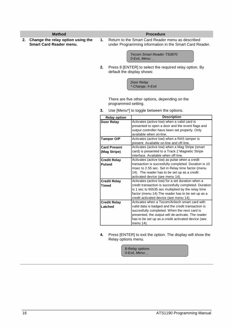
Method Procedure2. Change the relay option using the
Smart Card Reader menu.1. Return to the Smart Card Reader menu as described
under Programming information in the Smart Card Reader.
2. Press 8 [ENTER] to select the required relay option. Bydefault the display shows:
There are five other options, depending on theprogrammed setting.
3. Use [Menu*] to toggle between the options.
Relay option DescriptionDoor Relay Activates (active low) when a valid card is
presented to open a door and the event flags and output controller have been set properly. Only available when on-line.
Tamper O/P Activates (active low) when a RAS tamper is present. Available on-line and off-line.
Card Present (Mag Stripe)
Activates (active low) when a Mag Stripe (smart card) is presented to a Track 2 Magnetic Stripe interface. Available when off-line.
Credit Relay Pulsed
Activates (active low) as pulse when a credit transaction is succesfully completed. Duration is 10 msec to 2.55 sec. Set in Relay time factor (menu 14). The reader has to be set up as a credit activated device (see menu 14).
Credit Relay Timed
Activates (active low) for a set duration when a credit transaction is succesfully completed. Duration is 1 sec to 65535 sec multiplied by the relay time factor (menu 14).The reader has to be set up as a credit activated device (see menu 14).
Credit Relay Latched
Activates when a Tecom/Aritech smart card with valid data is badged and the credit transaction is succesfully completed. When the next card is presented, the output will de-activate. The reader has to be set up as a credit activated device (see menu 14).
4. Press [ENTER] to exit the option. The display will show theRelay options menu.
Door Relay*-Change, #-Exit
Tecom Smart Reader TS08700-Exit, Menu: _
8-Relay options0-Exit, Menu: _

ATS1190 Programming Manual 17
2.11. Disabling the use of configuration or “option” cardsThe Smart Card Reader can be set-up using a configuration or option card (both are the same). To disablechanging the configuration more then once with a configuration card, disable this option. There are twomethods to select the required option:
1. Using a configuration card programmed with the Smart Card Programmer ATS1620 and the ATS8100Titan Software package. This can be done when setting the address.
2. Using the Smart Card Reader menu.
Method Procedure1. Disable the use of configuration
cards when setting the address byprogramming a configuration cardusing the TITAN systemmanagement software and theSmart Card programmer (ATS1620).
1. Set the address as described under Setting the reader’saddress method 1, steps 1 and 2.
2. To enable, tick the read option card checkbox.
3. Follow steps 3 through 5 as described under Setting thereader’s address.
2. Disable the use of configurationcards using the Smart Card Readermenu.
1. Return to the Smart Card Reader menu as describedunder Programming information in the Smart Card Reader.
2. Press 9 [ENTER] to enter the Option Card setting. One oftwo screens appears:
Or
Default: Option card enabled
3. Use [Menu*] to toggle between the options.
4. Press [ENTER] to exit the option. The display shows theOption Card menu.
Note: To enable option cards again, use the Smart ReaderMenu to enable the option again, default the reader or setthis option in a configuration card if this option has notbeen used yet already. After disabling this option, aconfiguration card can only be used once.
Option Card Enabled*-Change, #-Exit
Option Card Disabled*-Change, #-Exit
Tecom Smart Reader TS08700-Exit, Menu: _
9-Option Card0-Exit, Menu: _

18 ATS1190 Programming Manual
2.12. Setting the egress controlEgress is available only in on-line mode and uses the LED2 input. When connected to ground, the door willopen. The relay option has to be set to Door Relay.
✍ Egress is also known as request-to-exit.
There are two methods to enable egress:
1. Using a configuration card programmed with the Smart Card Programmer ATS1620 and the ATS8100Titan Software package. This can be done at the same moment the address is set.
2. Using the Smart Card Reader menu.
Method Procedure1. Enable egress when setting the
address by programming aconfiguration card using the TITANsystem management software andthe Smart Card programmer (ATS1620).
1. Set the address as described under Setting the reader’saddress method 1, steps 1 and 2.
2. Select the required protocol from the list box labelledEgress control.
3. Follow steps 3 through 5 as described under Setting thereader’s address.
2. Enable egress using the SmartCard Reader menu.
1. Return to the Smart Card Reader menu as describedunder Programming information in the Smart Card Reader.
2. Press 10 [ENTER] to set the egress options. One of threescreens appears:
Or
Or
Default: Egress disabled
3. Use [Menu*] to toggle between the options.
4. Press [ENTER] to exit the option. The display shows theegress control menu.
Egress Disabled*-Change, #-Exit
Egress only*-Change, #-Exit
Tecom Smart Reader TS08700-Exit, Menu: _
Egress+Arm/Disarm*-Change, #-Exit
10-Egress control0-Exit, Menu: _
ATS1190 Programming Manual 19
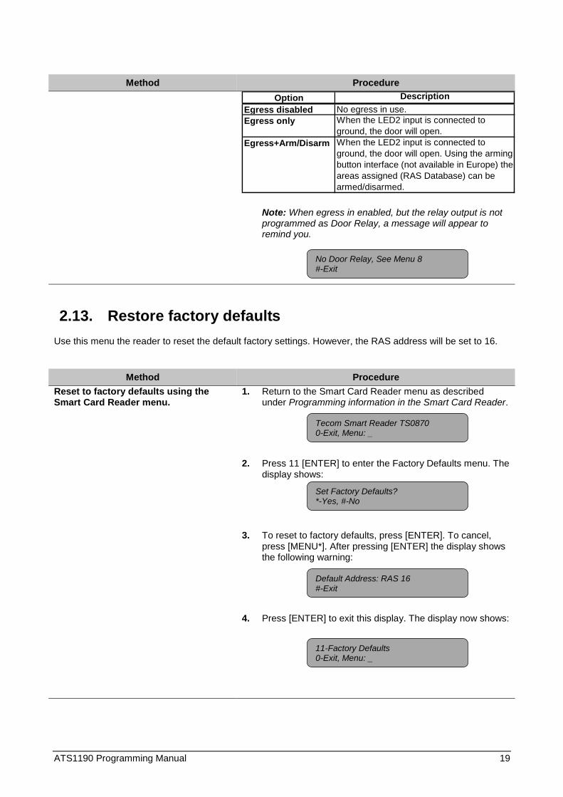
Method ProcedureOption Description
Egress disabled No egress in use.Egress only When the LED2 input is connected to
ground, the door will open.Egress+Arm/Disarm When the LED2 input is connected to
ground, the door will open. Using the arming button interface (not available in Europe) the areas assigned (RAS Database) can be armed/disarmed.
Note: When egress in enabled, but the relay output is notprogrammed as Door Relay, a message will appear toremind you.
2.13. Restore factory defaultsUse this menu the reader to reset the default factory settings. However, the RAS address will be set to 16.
Method ProcedureReset to factory defaults using theSmart Card Reader menu.
1. Return to the Smart Card Reader menu as describedunder Programming information in the Smart Card Reader.
2. Press 11 [ENTER] to enter the Factory Defaults menu. Thedisplay shows:
3. To reset to factory defaults, press [ENTER]. To cancel,press [MENU*]. After pressing [ENTER] the display showsthe following warning:
4. Press [ENTER] to exit this display. The display now shows:
No Door Relay, See Menu 8#-Exit
Set Factory Defaults?*-Yes, #-No
Tecom Smart Reader TS08700-Exit, Menu: _
11-Factory Defaults0-Exit, Menu: _
Default Address: RAS 16#-Exit
20 ATS1190 Programming Manual
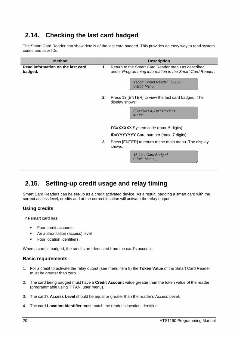
2.14. Checking the last card badgedThe Smart Card Reader can show details of the last card badged. This provides an easy way to read systemcodes and user IDs.
Method DescriptionRead information on the last cardbadged.
1. Return to the Smart Card Reader menu as describedunder Programming information in the Smart Card Reader.
2. Press 13 [ENTER] to view the last card badged. Thedisplay shows:
FC=XXXXX System code (max. 5 digits)
ID=YYYYYYY Card number (max. 7 digits)
3. Press [ENTER] to return to the main menu. The displayshows:
2.15. Setting-up credit usage and relay timingSmart Card Readers can be set-up as a credit activated device. As a result, badging a smart card with thecorrect access level, credits and at the correct location will activate the relay output.
Using credits
The smart card has:
� Four credit accounts,� An authorisation (access) level� Four location identifiers.
When a card is badged, the credits are deducted from the card’s account.
Basic requirements
1. For a credit to activate the relay output (see menu item 8) the Token Value of the Smart Card Readermust be greater than zero.
2. The card being badged must have a Credit Account value greater than the token value of the reader(programmable using TITAN, user menu).
3. The card’s Access Level should be equal or greater than the reader’s Access Level.
4. The card Location Identifier must match the reader’s location identifier.
Tecom Smart Reader TS08700-Exit, Menu: _
FC=XXXXX,ID=YYYYYYY#-Exit
13-Last Card Badged0-Exit, Menu: _

ATS1190 Programming Manual 21
5. Each time there is a credit transaction the user’s credit account is reduced by the token value of thereader (a credit account can also be set to a special value so no credit reduction occurs).
Explaining the items
Token value(0-65535, default = 0)
This is a value representing a currency, time or just a number. You can sethow many credits equal one token.
Example: At a library photocopier, each time an A4 copy is made with thecard, one token worth 10 cents is deducted. For an A3 sheet 2 tokens arededucted because of the larger paper size.
Credit account number(1-4, default = 1)
The credit account to subtract the token value from (one of four available).
Access level(1-16, default = 1)
Access (authorisation) level accepted by the reader (zero is invalid). Thecard’s access level must be equal or greater than the reader’s access levelfor the transaction to work.
Example: A manager might have an access level of 16, which means he canuse all photocopiers with Smart Card Readers installed in the building,including all photocopiers set to a lower access level. (I.e., 15-1). Otherpeople might have an access level of 5, which allows them to usephotocopiers with readers set to an access level of 5 or below.
Location identifier(1-4, default = 1)
Select a Location Identifier between the range 1 to 4 (zero is invalid). Thelocation identifier can represent an area, a floor, a group of floors in a multi-story building, a building, or a group of buildings.
Example: You might have already given some staff the highest (access)authorisation level of 16, but you want to stop them using the adminphotocopier.
Relay time factor(1-256, default = 5)
This is used to modify the pulse width output of the Credit Relay Pulsedoption and the activation time for the Credit Relay Timed option in Setting therelay option.
� The pulse width for the “Credit Relay Pulsed” is the Relay Time Factormultiplied by 0.01 seconds (10 milliseconds). This gives a pulse widthbetween 0.01 - 2.56 seconds.
� The activation time for the “Credit Relay Timed” option is the Relay TimeFactor multiplied by the Token Value of the reader. This gives a range ofbetween 1 second and around 193 days.
There are two methods to set-up credits and relay timing:
1. Using a configuration card programmed with the Smart Card Programmer ATS1620 and the ATS8100Titan Software package. This can be done at the same moment the address is set.
2. Using the Smart Card Reader menu.

22 ATS1190 Programming Manual
Method Procedure1. Set-up for credit usage whn setting
the address by programming aconfiguration card using the TITANsystem management software andthe Smart Card programmer (ATS1620).
1. Set the address as described under Setting the reader’saddress method 1, steps 1 and 2.
2. Set the token value in the edit box labelled “Reader tokenvalue”.
3. Select the reader’s credit account to subtract from in thelist box labelled “Reader credit account no.”.
4. Set the access level in the edit box labelled “Readeraccess level”.
5. Select the readers location number in the list box labelled“Readers location no.”.
6. Set the relay time factor in the edit box labelled “Outputtime factor”.
7. Follow steps 3 through 5 as described under Setting thereader’s address.
2. Set-up as a credit activated deviceusing the Smart Card Readermenu.
1. Return to the Smart Card Reader menu as describedunder Programming information in the Smart Card Reader.
2. Press 14 [ENTER] start setting up as a credit activateddevice. The display shows the Token Value to enter:
3. Enter the required token value and press [ENTER].
4. Enter the credit account to use and press [ENTER]
5. Enter the access level required and press [ENTER].
6. Enter the location number and press [ENTER].
7. Enter the relay time factor and press [ENTER]. If no CreditRelay is set in menu 8, a warning appears:
Account No: 1 (1-4)No: _
Access Level: 1(1-16)No: _
Location: 1(1-4)No: _
Relay Time Factor: 5(1-256)No: _
Token Value: 0 (0-65534)No: _
Tecom Smart Reader TS08700-Exit, Menu: _
No Credit Relay, See Menu 8#-Exit
ATS1190 Programming Manual 23
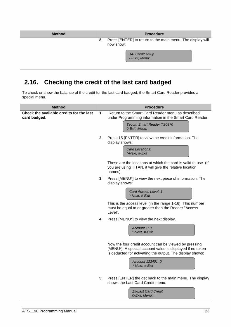
Method Procedure8. Press [ENTER] to return to the main menu. The display will
now show:
2.16. Checking the credit of the last card badgedTo check or show the balance of the credit for the last card badged, the Smart Card Reader provides aspecial menu.
Method ProcedureCheck the available credits for the lastcard badged.
1. Return to the Smart Card Reader menu as describedunder Programming information in the Smart Card Reader.
2. Press 15 [ENTER] to view the credit information. Thedisplay shows:
These are the locations at which the card is valid to use. (Ifyou are using TITAN, it will give the relative locationnames).
3. Press [MENU*] to view the next piece of information. Thedisplay shows:
This is the access level (in the range 1-16). This numbermust be equal to or greater than the Reader "AccessLevel".
4. Press [MENU*] to view the next display.
Now the four credit account can be viewed by pressing[MENU*]. A special account value is displayed if no tokenis deducted for activating the output. The display shows:
5. Press [ENTER] the get back to the main menu. The displayshows the Last Card Credit menu:
Card Locations:*-Next, #-Exit
14- Credit setup0-Exit, Menu: _
Tecom Smart Reader TS08700-Exit, Menu: _
Card Access Level: 1*-Next, #-Exit
Account 123401: 0*-Next, #-Exit
15-Last Card Credit0-Exit, Menu: _
Account 1: 0*-Next, #-Exit

24 ATS1190 Programming Manual
2.17. Setting the security modeThe security mode is used to determine if programmed Smart Cards with credits and user defined cards canbe read, or only blank, unprogrammed cards with a unique serial number and user defined cards. To use theunsecured mode, a special memory module is required. This option can be set using one of two methods:
1. Using a configuration card programmed with the Smart Card Programmer ATS1620 and the ATS8100Titan Software package. This can be done when setting the address.
2. Using the Smart Card Reader menu.
Method Procedure1. Set the security mode when setting
the address by programming aconfiguration card using the TITANsystem management software andthe Smart Card programmer (ATS1620).
1. Set the address as described under Setting the reader’saddress method 1, steps 1 and 2.
2. Select the required option in the list box labelled Securitymode.
3. Follow steps 3 through 5 as described under Setting thereader’s address.
2. Set the security mode using theSmart Card Reader menu.
1. Return to the Smart Card Reader menu as describedunder Programming information in the Smart Card Reader.
2. Press 16 [ENTER] to enter the security mode setting. Oneof two screens appears:
Or
Default: Secured
3. Use [Menu*] to toggle between the options.
4. Press [ENTER] to exit the option. The display shows theOption Card menu.
Note: To enable option cards again, use the Smart ReaderMenu to enable the option again, default the reader or setthis option in a configuration card if this option has notbeen used yet already. After disabling this option, aconfiguration card can only be used once.
Secured mode*-Change, #-Exit
Unsecured mode*-Change, #-Exit
Tecom Smart Reader TS08700-Exit, Menu: _
16- Security mode0-Exit, Menu: _
ATS1190 Programming Manual 25
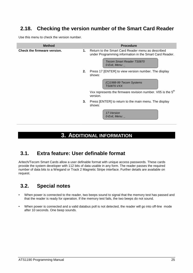
2.18. Checking the version number of the Smart Card ReaderUse this menu to check the version number.
Method ProcedureCheck the firmware version. 1. Return to the Smart Card Reader menu as described
under Programming information in the Smart Card Reader.
2. Press 17 [ENTER] to view version number. The displayshows:
Vxx represents the firmware revision number. V05 is the 5th
version.
3. Press [ENTER] to return to the main menu. The displayshows:
3. ADDITIONAL INFORMATION
3.1. Extra feature: User definable formatAritech/Tecom Smart Cards allow a user definable format with unique access passwords. These cardsprovide the system developer with 112 bits of data usable in any form. The reader passes the requirednumber of data bits to a Wiegand or Track 2 Magnetic Stripe interface. Further details are available onrequest.
3.2. Special notes• When power is connected to the reader, two beeps sound to signal that the memory test has passed and
that the reader is ready for operation. If the memory test fails, the two beeps do not sound.
• When power is connected and a valid databus poll is not detected, the reader will go into off-line modeafter 10 seconds. One beep sounds.
(C)1988-99 Tecom SystemsTS0870.VXX
Tecom Smart Reader TS08700-Exit, Menu: _
17-Version0-Exit, Menu: _
26 ATS1190 Programming Manual
4. GLOSSARY OF TERMS
Access control The control of entry to, or exit from, a security area.
Alarm The state of a security system when a device connected to a zone isactivated and the condition of the area is such that activation should besignalled. E.g. a door lock is broken, causing a siren to sound.
Alarm group Alarm groups define the options available to users, arming stations ordoor reader to allow alarm control. Alarm groups are defined by a set ofareas, alarm control functions and menu options.Zone types for area control (key switches) also make use of alarm groups.
Alarm control The control over alarm functions.
Area A part of a premise that has specific security requirements. The ATSsystem allows any premises to be divided into 16 areas of differentsecurity requirements. Each area has its own zones. Each area isidentified by a number and a name. E.g. Area 1 Office, Area 2 Workshop,Area 3 Boardroom, etc.
Armed The condition of an area where a change in the status of any zone (fromnormal to active) causes an alarm. An area or premise is only armedwhen it is unoccupied. Some zones (like vaults) can remain armedcontinually.
Arming stations (RAS) A device that is the user’s control panel for security functions for anarea(s) or for access points (doors). The arming station can be an ATSconsole (LCD keypad, reader) or any other device that can be used toperform security function, such as arm/disarm, open doors, etc.
Control panel An electronic device that is used to gather all data from zones on thepremises. Depending on programming and status of areas, it will generatealarm signals. If required, alarms and other events can be reported to acentral station.
Cursor A flashing underline character on the liquid crystal display (LCD) thatindicates where the next character entered on the keypad will appear.
DGP Data Gathering Panel. A device that collects data from other securitydevices within an area, and transfers it to the ATS control panel or 4-door/4-lift DGP.
Disarmed The condition of an area when it is occupied and when the securitysystem has been set so that normal activity does not set off an alarm.
Door contact A magnetic contact used to detect if a door or window is opened.
Door control The control over door functions.
Door group An ATS feature that assigns a group of doors or lifts to a user, in order toallow access to those doors/lifts. Access to each door in a group can berestricted via a timezone.
Egress (request-to-exit) A button provided inside a door (egress button) that allows users to exitwithout using the door reader.
Engineer Personnel from an installer who can install and service the control panel.
Event flags A signal activated by a zone condition, area condition, system status orfault condition, door command (on doors 1 to 16), or shunt condition. Themain purpose of an event flag is to activate an output.

ATS1190 Programming Manual 27
Floor group An ATS feature that assigns a group of floors to a user to allow selectionof floors when accessing a lift reader. Access to each floor in a group canbe restricted via a timezone.
Floor control See Door control.
History A list of past alarm and access control events stored in memory that canbe viewed on an LCD arming station or sent to a printer.
Installer A company that installs and services security equipment.
Keypad A remote arming station with keys to input data (keypad). Used toprogram the control panel, perform user functions, view alarms, etc.
LCD Liquid Crystal Display. The part of an arming station where messages aredisplayed.
LED Light Emitting Diode. A light indicator on an arming station which conveysa condition. E.g.; area in alarm, communication fault, etc.
Normal/Active/Tamper/Inhibited Describes the condition of a zone.
Normal: The zone is NOT activated. E.g. Fire Exit Door closed
Active: The zone is activated. E.g. Fire Exit Door open
Tamper: The zone is open or short circuited. Someone may havetried to tamper the security device.
Inhibited: The zone has been inhibited from indicating normal oractive status. It is excluded from functioning as part of thesystem.
On-line/off-line Operational/non-operational. A device may be off-line due to a malfunctionin the device itself or it may be disconnected from the control.
Output controller A PCB module that connects to the ATS control panel or a DGP to providerelay or open collector outputs. When programming, 1 Output controllerequals 8 outputs.
Poll An inquiry message continually sent by the ATS control panel to DGP’sand arming stations. Polling allows the remote unit to transfer data to thecontrol panel.
RAS Remote Arming Station. See Arming station.
Reader A device used for access control that can read cards to allow access.Depending on the needs and the type of cards, the reader can forexample be a magnetic swipe reader or proximity reader.
Request-to-exit (also egress) See egress zone. Request-to-exit is often abbreviated to RTE.
Shunt A procedure that automatically inhibits a zone from generating an alarmwhen it is activated. E.g. shunts stop a door generating an alarm whenopened for a short time.
Smart Card An intelligent card with embedded memory and processing capabilities.Smart cards can be programmed with data using programmers. Smartcards are programmed as users in the Advisor Master system to opendoors or arm and disarm areas.
Tamper A situation where a zone, an arming station, control panel, DGP orassociated wiring are tampered with, or accidentally damaged. The ATStamper facility activates a signal when tamper occurs.

28 ATS1190 Programming Manual
Tamper alarms from zones are called zone tampers.
Timezone A program setting which identifies specific time periods on specific days.Timezones are allocated to ATS functions to control the activity of thatfunction by time and day and are primary used to restrict access. E.g.automatically arm or disarm areas or open doors.
User Anybody using the ATS system. Users are identified by the ATS systemby a unique number that is associated with the user’s PIN code.
Zone An electrical signal from a security device (PIR detector, door contact) tothe ATS system. Each device is identified by a zone number and name.e.g. 14 Reception Holdup Button, 6 Fire Exit Door.

ATS1190 Programming Manual 29
5. INDEX
Beeper options, 13Card number, 20Check the last card badged, 20Configuration, 3
beeper options, 13check the last card badged, 20check version, 25connected to control panel or DGP, 3credit activated device, 20disable use of configuration or option card, 17LED off-line options, 9night light, 11on-line LED options, 7polling the reader, 3, 6protocol options, 12relay option, 15restore factory defaults, 19set security mode, 24setting egress (request to exit), 18setting the reader address, 5using configuration or option card, 3valid card flash, 10via databus, 3watch dog, 14
Configuration or option card, 17, 24Credit card device. See CreditsCredits
access level, 20, 21basic requirements, 20check last card badged, 23credit account, 20credit account number, 21location identifier, 20location number, 21no credit required, 21relay time factor, 21set-up, 20token value, 20, 21using credits, 20view credit information, 23
Databuslocal, 2off-line, 2, 9, 14, 25
on-line, 2, 7system, 2
Glossary of terms, 26Interfaces, 2, 9, 14, 25
Magnetic stripe, 2, 15on-line, 2, 7, 18watch dog, 15Wiegand, 2, 15
LED options, 7, 9Magnetic stripe interface, 2Night light, 11Off-line, 2, 9, 14, 25On-line, 2, 7Protocol options, 12Reader
front view, 2Reader address, 5Relay option, 15Relay options
egress (Request to exit), 18relay time factor, 16, 21
Request-to-exit (egress), 18Restore factory defaults, 19Security mode, 24Setting the open collector output, 15Smart card programmer, 2, 3Smart card reader
configuration, 3configuring with TITAN, 3
Special notes, 25System code, 20TITAN, 2
configuring Smart card readers, 3User definable format, 25Using credits
setting the relay, 16Valid card flash, 10Version number, 25View card information, 20, 23View credit of last card badged, 23Watch dog, 14Wiegand interface, 2

14 5015 999-2
6. PROGRAMMING MAP
Tecom Smart Reader TS0870
1-Leds On-Line
2-Leds Off-Line
3-Valid Card Flash
4-Night Light
5-Protocol Options
6-Beeper Options
7-Watch Dog Option
8-Relay Options
9-Option Card
10-Egress Control
11-Factory Defaults
12-Reader Address
13-Last Card
14-Credit Setup
15-Last Card Credit
16-Security Mode
17-Version
Red Led
Token Value
Account No
Access Level
Location
Relay Time Factor
Remote RAS Setup28. To Remote Device
Blue Led